WO2024253112A1 - コネクタおよび雌端子 - Google Patents
コネクタおよび雌端子 Download PDFInfo
- Publication number
- WO2024253112A1 WO2024253112A1 PCT/JP2024/020449 JP2024020449W WO2024253112A1 WO 2024253112 A1 WO2024253112 A1 WO 2024253112A1 JP 2024020449 W JP2024020449 W JP 2024020449W WO 2024253112 A1 WO2024253112 A1 WO 2024253112A1
- Authority
- WO
- WIPO (PCT)
- Prior art keywords
- peripheral wall
- cylindrical
- female terminal
- protrusion
- winding
- Prior art date
- Legal status (The legal status is an assumption and is not a legal conclusion. Google has not performed a legal analysis and makes no representation as to the accuracy of the status listed.)
- Ceased
Links
Images





Classifications
-
- H—ELECTRICITY
- H01—ELECTRIC ELEMENTS
- H01R—ELECTRICALLY-CONDUCTIVE CONNECTIONS; STRUCTURAL ASSOCIATIONS OF A PLURALITY OF MUTUALLY-INSULATED ELECTRICAL CONNECTING ELEMENTS; COUPLING DEVICES; CURRENT COLLECTORS
- H01R13/00—Details of coupling devices of the kinds covered by groups H01R12/70 or H01R24/00 - H01R33/00
- H01R13/02—Contact members
- H01R13/10—Sockets for co-operation with pins or blades
- H01R13/11—Resilient sockets
-
- H—ELECTRICITY
- H01—ELECTRIC ELEMENTS
- H01R—ELECTRICALLY-CONDUCTIVE CONNECTIONS; STRUCTURAL ASSOCIATIONS OF A PLURALITY OF MUTUALLY-INSULATED ELECTRICAL CONNECTING ELEMENTS; COUPLING DEVICES; CURRENT COLLECTORS
- H01R13/00—Details of coupling devices of the kinds covered by groups H01R12/70 or H01R24/00 - H01R33/00
- H01R13/40—Securing contact members in or to a base or case; Insulating of contact members
- H01R13/42—Securing in a demountable manner
Definitions
- This disclosure relates to connectors and female terminals.
- a connector mounted on a vehicle that includes a housing and a female terminal held in the housing.
- the columnar connection portion of the male terminal is inserted into the cylindrical connection portion of the female terminal, and the columnar connection portion is electrically connected.
- This type of female terminal uses the biasing force of a biasing member such as a coil spring to ensure stable contact pressure against the columnar connection portion of the male terminal (see, for example, Patent Document 1).
- An object of the present disclosure is to provide a connector and a female terminal that can suppress displacement of the female terminal inside the housing.
- the connector of the present disclosure includes a female terminal and a housing that holds the female terminal
- the female terminal includes a first peripheral wall having a first cylindrical portion, a second peripheral wall having a second cylindrical portion that faces the first cylindrical portion, a cylindrical connecting portion formed by the first cylindrical portion and the second cylindrical portion, a roll pressing portion that limits the separation distance between the first inner surface of the first cylindrical portion and the second inner surface of the second cylindrical portion, and a protrusion that protrudes from the outer surface of the second peripheral wall
- the roll pressing portion is integrally formed with the first peripheral wall
- the roll pressing portion is folded back from the first peripheral wall while holding the edge of the second peripheral wall inward, and is in contact with the outer surface of the second peripheral wall
- the roll pressing portion and the protrusion are arranged side by side on the same straight line along a first axis
- the housing has a groove-shaped receiving portion into which the roll pressing portion and the protrusion are inserted.
- the connector and female terminal disclosed herein have the advantage of being able to suppress displacement of the female terminal inside the housing.
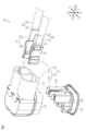
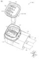
- FIG. 1 is a perspective view showing a wire harness according to an embodiment.
- FIG. 2 is an exploded perspective view showing the wire harness of the embodiment.
- FIG. 3 is an exploded perspective view showing the wire harness of the embodiment.
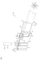
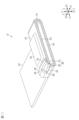
- FIG. 4 is a perspective view showing a part of the wire harness of the embodiment.
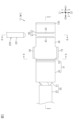
- FIG. 5 is a plan view showing a part of the wire harness of the embodiment.
- FIG. 6 is a plan view showing a portion of the wire harness of the embodiment.
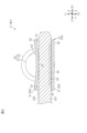
- FIG. 7 is a cross-sectional view (cross-sectional view taken along line 7-7 in FIGS. 5 and 6) showing a part of the wire harness of the embodiment.
- FIG. 8 is a cross-sectional view (cross-sectional view taken along line 8-8 in FIGS.
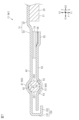
- FIG. 9 is a cross-sectional view showing a female terminal of one embodiment (a cross-sectional view taken along line 9-9 in FIGS. 5 and 6).
- FIG. 10 is a cross-sectional view showing a female terminal of one embodiment (cross-sectional view taken along line 10-10 in FIG. 9).
- FIG. 11 is a cross-sectional perspective view showing a female terminal of one embodiment.
- FIG. 12 is an exploded perspective view showing a part of the wire harness of the embodiment.
- FIG. 13 is a plan view showing a part of the wire harness of the embodiment.
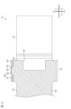
- FIG. 14 is a cross-sectional view (cross-sectional view taken along line 14-14 in FIG. 13) showing a portion of the wire harness of the embodiment.
- FIG. 15 is a cross-sectional view (cross-sectional view taken along line 15-15 in FIG. 14) showing a portion of the wire harness of the embodiment.
- a connector of the present disclosure comprises a female terminal and a housing for holding the female terminal, the female terminal having a first peripheral wall having a first cylindrical portion, a second peripheral wall having a second cylindrical portion opposite the first cylindrical portion, a cylindrical connecting portion constituted by the first cylindrical portion and the second cylindrical portion, a roll pressing portion for limiting a separation distance between a first inner surface of the first cylindrical portion and a second inner surface of the second cylindrical portion, and a convex portion protruding from an outer surface of the second peripheral wall, the roll pressing portion being integrally formed with the first peripheral wall, the roll pressing portion being folded back from the first peripheral wall while holding an edge of the second peripheral wall inward, and being in contact with the outer surface of the second peripheral wall, the roll pressing portion and the convex portion being arranged side by side on the same line along a first axis, and the housing having a groove-shaped accommodating portion into which the roll pressing portion and
- the female terminal's roll pressing portion and protrusion are inserted into the housing's accommodating portion.
- the roll pressing portion is folded back from the first peripheral wall and is in contact with the outer surface of the second peripheral wall. Therefore, the roll pressing portion protrudes outward from the outer surface of the second peripheral wall.
- a large gap may be formed between the portion of the female terminal where the roll pressing portion is not formed and the inner surface of the accommodating portion.
- a problem occurs in that the female terminal is easily displaced inside the accommodating portion.
- the protrusion protruding from the outer surface of the second peripheral wall is arranged in the same straight line as the roll pressing portion.
- the gap between the portion of the female terminal where the roll pressing portion is not formed and the inner surface of the accommodating portion can be reduced. This makes it possible to suitably suppress the female terminal from displacing inside the accommodating portion. In turn, this makes it possible to suitably suppress the female terminal from displacing inside the accommodating portion.
- the first peripheral wall is formed in a band shape extending along a first direction
- the second peripheral wall is formed in a band shape extending along the first direction
- the first inner surface is a surface facing a second direction intersecting with the first direction
- the second inner surface is a surface facing a second opposite direction that is the opposite direction of the second direction
- the outer surface of the second peripheral wall is a surface facing the second direction
- the axial direction of the cylindrical connection part extends along a third direction intersecting with both the first direction and the second direction
- the winding pressing part is folded back from the end face of the first peripheral wall in the third direction while embracing the end face of the second peripheral wall in the third direction inside
- the protruding part is provided so as to overlap the winding pressing part in a plan view seen from the third direction, and the protruding part may protrude from the outer surface of the second peripheral wall in the second direction.
- the convex portion is formed to protrude from the outer surface of the second peripheral wall in the second direction. This makes it possible to reduce the gap between the female terminal and the inner surface of the accommodating portion in the second direction. Therefore, the female terminal can be effectively prevented from tilting in the second direction inside the accommodating portion. As a result, the axial direction of the tubular connecting portion of the female terminal can be prevented from tilting in the second direction.
- a first protruding amount of the convex portion from an outer surface of the second circumferential wall may be equal to a second protruding amount of the winding pressing portion from the outer surface of the second circumferential wall.
- the first protrusion amount of the protrusion is equal to the second protrusion amount of the winding pressure portion.
- the housing has a housing main body that accommodates the female terminal therein and a retainer that is attached to the housing main body, the retainer has a restricting portion that is inserted into the housing main body and restricts the movement of the female terminal, and the restricting portion may have the accommodating portion.
- the restricting portion may have an engaging wall that engages with the protruding portion in the first direction. According to this configuration, the protrusion of the female terminal is engaged with the engaging wall in the first opposite direction that is the opposite direction to the first direction, thereby making it possible to preferably prevent the female terminal from moving in the first opposite direction inside the accommodating portion.
- the female terminal may further have a connecting portion that connects the first peripheral wall and the second peripheral wall, and the connecting portion may be formed integrally with the first peripheral wall and may also be formed integrally with the second peripheral wall.
- the first peripheral wall and the second peripheral wall are connected by a connecting portion that is formed integrally with both the first peripheral wall and the second peripheral wall. This allows the first peripheral wall and the second peripheral wall to be formed integrally through the connecting portion. Therefore, the female terminal can be formed by performing bending processing or the like on a single metal plate. As a result, the structure of the female terminal can be simplified.
- the connecting portion is formed to extend in the second direction from an end face of the first peripheral wall in a third opposite direction, which is the opposite direction to the third direction, toward an end face of the second peripheral wall in the third opposite direction, and the connecting portion may be arranged to overlap the winding pressing portion in a plan view seen from the third direction.
- a winding presser is provided on the opposite side of the connecting portion with the first peripheral wall in between. Therefore, the winding presser can suitably restrict the connecting portion from opening, i.e., the distance between the first peripheral wall and the second peripheral wall from increasing. As a result, the winding presser can suitably restrict the distance between the first inner surface constituting the tubular connecting portion and the second inner surface constituting the tubular connecting portion from increasing.
- the female terminal may further have a protective portion provided at the end of the first peripheral wall in the first direction, the protective portion being formed integrally with the first peripheral wall, the protective portion being formed so as to be folded back from the end of the first peripheral wall in the first direction while locating the end of the second peripheral wall in the first direction inside, the protective portion having a protective wall provided opposite the end of the second peripheral wall in the first direction in the second direction, and the protective wall may be provided at a distance from the end of the second peripheral wall in the first direction.
- the protective wall of the protective section formed integrally with the first peripheral wall is provided facing and spaced apart from the end of the second peripheral wall in the first direction. Therefore, even if, for example, an excessively large external force is unintentionally applied to the end of the second peripheral wall in the first direction, and the second peripheral wall is deformed as a result of the external force so as to move away from the first peripheral wall, the deformation can be suitably prevented by the protective wall.
- the winding pressing portion may be provided at an end of the first peripheral wall in a first opposite direction that is the opposite direction to the first direction
- the protrusion may be provided at an end of the second peripheral wall in the first opposite direction
- the tubular connecting portion may be provided at an intermediate position between the winding pressing portion and the protective portion in the first direction.
- the winding pressing portion is provided at a different position from the tubular connection portion in the first direction.
- Such a winding pressing portion can limit the distance between the first peripheral wall and the second peripheral wall from increasing.
- the winding pressing portion can limit the distance between the first inner surface constituting the tubular connection portion and the second inner surface constituting the tubular connection portion from increasing.
- the female terminal of the present disclosure comprises a first peripheral wall having a first cylindrical portion, a second peripheral wall having a second cylindrical portion facing the first cylindrical portion, a cylindrical connecting portion constituted by the first cylindrical portion and the second cylindrical portion, a roll pressing portion that limits the separation distance between the first inner surface of the first cylindrical portion and the second inner surface of the second cylindrical portion, and a protrusion that protrudes from the outer surface of the second peripheral wall, the roll pressing portion being integrally formed with the first peripheral wall, the roll pressing portion being folded back from the first peripheral wall while holding the edge of the second peripheral wall inward, and being in contact with the outer surface of the second peripheral wall, and the roll pressing portion and the protrusion being arranged side by side on the same straight line along the first axis.
- the "cylindrical” used in the description of this specification includes not only those in which a peripheral wall is formed continuously around the entire circumference, but also those in which a plurality of parts are combined to form a cylindrical shape, and those having a notch in a part of the circumference such as a C-shape or U-shape.
- the shape of the "cylindrical” includes, but is not limited to, a circle, an ellipse, and a polygon with sharp or rounded corners.
- “opposite” refers to surfaces or members being in front of each other, including not only the case where they are completely in front of each other, but also the case where they are partially in front of each other.
- the wire harness W1 includes one or more (two in this embodiment) electric wires 20 and a connector C1 attached to the end of the electric wire 20.
- the wire harness W1 electrically connects, for example, electric devices for a vehicle to each other. Examples of electric devices for a vehicle include an inverter and a motor for driving wheels.
- the connector C1 is electrically connected to a mating connector provided on the electric device.
- the mating connector includes, for example, one or more (two in this embodiment) male terminals 200 (see FIG. 4) that are mating terminals, and a mating housing that holds the two male terminals 200. Note that the directions in each drawing do not necessarily represent the postures of the connector C1 and the wire harness W1 when in use.
- the connector C1 includes a housing 30 and a plurality of female terminals 31 connected to the ends of a plurality of electric wires 20.
- the housing 30 holds the plurality of female terminals 31.
- the housing 30 includes a housing body 110 that houses the female terminals 31 therein, and a retainer 120 that is attached to the housing body 110.
- Each drawing illustrates an X-axis, a Y-axis, and a Z-axis that are mutually perpendicular.
- Each drawing illustrates a first direction X1 that is one direction in the X-axis direction along the X-axis, and a first opposite direction X2 that is the opposite direction to the first direction X1.
- Each drawing illustrates a second direction Y1 that is one direction in the Y-axis direction along the Y-axis, and a second opposite direction Y2 that is the opposite direction to the second direction Y1.
- Each drawing illustrates a third direction Z1 that is one direction in the Z-axis direction along the Z-axis, and a third opposite direction Z2 that is the opposite direction to the third direction Z1.
- the directions described above are directions when the connector C1 is assembled to the end of the electric wire 20, unless otherwise specified.
- the female terminal 31 and the electric wire 20 are inserted into the housing body 110 along the first direction X1.
- a retainer 120 is attached to the housing body 110 along the third opposite direction Z2.
- a mating connector is connected to the connector C1 along the third opposite direction Z2.
- the male terminal 200 (see Figure 4) of the mating connector is inserted into the housing body 110 along the third opposite direction Z2.
- Each electric wire 20 has a conductive core wire 21 and an insulating coating 22 that surrounds the outer periphery of the core wire 21 and has insulating properties.
- the core wire 21 may be, for example, a stranded wire made of a plurality of metal wires twisted together or a single-core wire made of a single conductor.
- the core wire 21 may be made of, for example, a copper-based or aluminum-based metal material.
- the insulating coating 22 covers, for example, the outer periphery of the core wire 21 over the entire circumferential direction.
- the insulating coating 22 is made of, for example, an insulating resin material.
- An end portion of the core wire 21 in the first direction X1 is exposed from the insulating coating 22.
- a female terminal 31 is connected to the end portion of the core wire 21 in the first direction X1 exposed from the insulating coating 22.
- 3, an end portion of the electric wire 20 in the first direction X1 is accommodated inside the housing main body 110.
- the electric wire 20 is led out from an end portion of the housing main body 110 in the first opposite direction X2.
- the two female terminals 31 are electrically connected to the two electric wires 20, respectively.
- the two female terminals 31 are arranged side by side along the Y-axis direction, for example.
- the two female terminals 31 have, for example, the same structure as each other.
- the description will be given focusing on the female terminal 31 arranged on the second direction Y1 side out of the two female terminals 31.
- Each female terminal 31 has a wire connection portion 32 that is connected to an end of the electric wire 20, and a terminal connection portion 33 that extends from the end of the wire connection portion 32 in the first direction X1 toward the first direction X1.
- Each female terminal 31 is, for example, a single part in which the wire connection portion 32 and the terminal connection portion 33 are continuously and integrally formed.
- Each female terminal 31 is formed, for example, by bending or combining a metal plate material.
- Each female terminal 31 in this embodiment is formed by bending a single metal plate material.
- Each female terminal 31 is, for example, made of metal. For example, a copper-based or aluminum-based metal material can be used as the material for each female terminal 31.
- the electric wire connection portion 32 is connected to the end of the core wire 21 exposed from the insulating coating 22.
- the electric wire connection portion 32 is formed, for example, in a flat plate shape.
- the electric wire connection portion 32 extends, for example, in a band shape along the X-axis direction.
- the electric wire connection portion 32 is connected to the core wire 21, for example, by crimping or ultrasonic welding. This electrically and mechanically connects the electric wire connection portion 32 and the core wire 21.
- the terminal connection portion 33 is a female terminal portion that is connected to a male terminal 200 of a mating connector.
- the male terminal 200 has a columnar columnar connection portion 201.
- the columnar connection portion 201 is formed in a cylindrical shape.
- the terminal connection part 33 has a first peripheral wall 40 having a first cylindrical portion 41, and a second peripheral wall 50 having a second cylindrical portion 51 facing the first cylindrical portion 41.
- the terminal connection part 33 has a cylindrical connection part 60 composed of the first cylindrical portion 41 and the second cylindrical portion 51.
- the terminal connection part 33 has, for example, a connecting part 70, a protruding part 80, a winding pressing part 90, and a protective part 100.
- the first peripheral wall 40 and the second peripheral wall 50 face each other in the Y-axis direction.
- the first peripheral wall 40 is formed in a band shape extending along the first direction X1.
- the first peripheral wall 40 extends from the end of the electric wire connection portion 32 in the first direction X1 toward the first direction X1.
- the electric wire connection portion 32 extends from the end of the first opposite direction X2 of the first peripheral wall 40 toward the first opposite direction X2.
- the first peripheral wall 40 is formed in a flat plate shape, for example.
- the first peripheral wall 40 has a predetermined width along the Z-axis direction.
- the first peripheral wall 40 has a predetermined thickness along the Y-axis direction.
- the first peripheral wall 40 has an inner surface facing the second peripheral wall 50 and an outer surface provided on the opposite side of the inner surface in the Y-axis direction.
- the second peripheral wall 50 is formed in a band shape extending along the first direction X1.
- the second peripheral wall 50 is formed, for example, in a flat plate shape.
- the second peripheral wall 50 has a predetermined width along the Z-axis direction.
- the second peripheral wall 50 has a predetermined thickness along the Y-axis direction.
- the second peripheral wall 50 has an inner surface facing the inner surface of the first peripheral wall 40 and an outer surface provided on the opposite side of the inner surface in the Y-axis direction.
- the inner surface of the second peripheral wall 50 is provided spaced apart from the inner surface of the first peripheral wall 40 in the Y-axis direction, for example.
- the second peripheral wall 50 extends, for example, parallel to the first peripheral wall 40.
- the first cylindrical portion 41 is provided at a middle position in the X-axis direction of the first peripheral wall 40.
- the first cylindrical portion 41 is provided between the winding pressing portion 90 and the protective portion 100 in the X-axis direction.
- the first cylindrical portion 41 is formed, for example, in a semi-cylinder shape as a whole. As shown in FIG. 5, the first cylindrical portion 41 extends along the Z-axis direction. The first cylindrical portion 41 extends over the entire length of the first peripheral wall 40 in the Z-axis direction.
- the second cylindrical portion 51 is provided at a middle position in the X-axis direction of the second peripheral wall 50.
- the second cylindrical portion 51 is provided between the winding pressing portion 90 and the protective portion 100 in the X-axis direction.
- the second cylindrical portion 51 is formed, for example, in a semi-split cylinder shape as a whole.
- the second cylindrical portion 51 extends along the Z-axis direction.
- the second cylindrical portion 51 extends over the entire length of the second peripheral wall 50 in the Z-axis direction.
- the first cylindrical portion 41 has a first inner surface 42 facing the second direction Y1.
- the second cylindrical portion 51 has a second inner surface 52 facing the second opposite direction Y2.
- the first inner surface 42 and the second inner surface 52 face each other in the Y-axis direction.
- the first cylindrical portion 41 and the second cylindrical portion 51 are curved toward the direction in which they are separated from each other.
- the first inner surface 42 of the first cylindrical portion 41 and the second inner surface 52 of the second cylindrical portion 51 form an internal space of the cylindrical connection portion 60.
- the cylindrical connection portion 60 is a connection portion into which the columnar connection portion 201 of the male terminal 200 is inserted and which is electrically connected to the columnar connection portion 201. As shown in FIG.
- the axial direction of the cylindrical connection portion 60 extends, for example, in a direction intersecting the direction in which the electric wire 20 extends (here, the X-axis direction), and in this embodiment, along the Z-axis direction.
- the cylindrical connection portion 60 is open at both ends in the Z-axis direction. That is, the cylindrical connection part 60 opens in the third direction Z1 and also opens in the third opposite direction Z2.
- the columnar connection part 201 is inserted into the cylindrical connection part 60 along the third opposite direction Z2.
- the tubular connection part 60 is formed, for example, in a cylindrical shape as a whole.
- the tubular connection part 60 has, for example, a maximum inner diameter dimension that is smaller than the maximum outer diameter dimension of the columnar connection part 201.
- the tubular connection part 60 is configured so that the columnar connection part 201 is press-fitted into it.
- the outer surface of the first cylindrical portion 41 is formed into a curved surface whose cross section, obtained by cutting the first cylindrical portion 41 on a plane parallel to the X-axis direction, is curved in an arc shape.
- the outer surface of the first cylindrical portion 41 is formed to protrude in an arc shape in cross section toward the radial outward direction of the cylindrical connection portion 60.
- the first inner surface 42 of the first cylindrical portion 41 is formed to recess in an arc shape in cross section toward the radial outward direction of the cylindrical connection portion 60.
- the first inner surface 42 of the first cylindrical portion 41 is provided with a plurality of (two in this embodiment) linear contact portions 43 that protrude from the first inner surface 42 radially inward of the cylindrical connection portion 60.
- the two linear contact portions 43 are provided at positions spaced apart from each other in the circumferential direction of the cylindrical connection portion 60.
- the two linear contact portions 43 are provided, for example, so as to partially oppose each other in the X-axis direction. As shown in FIG. 5, each linear contact portion 43 extends along the axial direction of the cylindrical connection portion 60 (here, the Z-axis direction).
- the curvature of the first inner surface 42 having the two linear contact portions 43 is set to be smaller than the curvature of the outer peripheral surface of the columnar connection portion 201 of the male terminal 200. This allows the two linear contact portions 43 to be in suitable contact with the outer peripheral surface of the columnar connection portion 201. At this time, each linear contact portion 43 is in linear contact with the outer peripheral surface of the columnar connection portion 201 along the axial direction of the tubular connection portion 60. In other words, each linear contact portion 43 is in linear contact with the outer peripheral surface of the columnar connection portion 201.
- the outer surface of the second cylindrical portion 51 is formed into a curved surface whose cross section, obtained by cutting the second cylindrical portion 51 on a plane parallel to the X-axis direction, is curved in an arc shape.
- the outer surface of the second cylindrical portion 51 is formed to protrude in an arc shape in cross section toward the radial outward direction of the cylindrical connection portion 60.
- the second inner surface 52 of the second cylindrical portion 51 is formed to recess in an arc shape in cross section toward the radial outward direction of the cylindrical connection portion 60.
- the outer surface of the second cylindrical portion 51 is provided with a recessed portion 53 that is recessed from the outer surface toward the radially inward direction of the cylindrical connection portion 60.
- the planar shape of the recessed portion 53 as viewed from the Y-axis direction is, for example, rectangular.
- the recessed portion 53 is provided, for example, at a midpoint in the Z-axis direction of the second cylindrical portion 51 and at a midpoint in the X-axis direction of the second cylindrical portion 51.
- the second inner surface 52 of the second cylindrical portion 51 is provided with a protrusion 54 that protrudes from the second inner surface 52 toward the radially inward direction of the cylindrical connection portion 60.
- the protrusion 54 is provided, for example, on the second inner surface 52 of the second cylindrical portion 51 in the portion where the recessed portion 53 is formed.
- the protrusion 54 is formed, for example, in a shape in which the cross-sectional shape of the protrusion 54 cut on a plane parallel to the axial direction (here, the Z-axis direction) of the cylindrical connection portion 60 protrudes in an arc shape toward the radially inward direction of the cylindrical connection portion 60.
- the protrusion 54 is formed so as to protrude in an arc shape toward the radially inward direction of the cylindrical connection portion 60 from the second inner surface 52.
- the protrusion 54 extends, for example, along the circumferential direction of the cylindrical connection portion 60.
- the protrusion 54 extends, for example, along the axial direction of the cylindrical connection portion 60.
- the protrusion 54 is in point contact with the outer peripheral surface of the columnar connection portion 201 of the male terminal 200.
- the protrusion 54 can be formed, for example, by embossing.
- the protrusion 54 is formed in an embossed shape by applying pressure to the outer surface of the second cylindrical portion 51 with a mold.
- Each of the axial ends of the cylindrical connection part 60 has, for example, a guide part 61.
- Each guide part 61 is formed so that the opening width (here, the inner diameter) of the cylindrical connection part 60 increases as it approaches the opening end in the axial direction of the cylindrical connection part 60.
- Each guide part 61 is formed, for example, by the inner surface of the cylindrical connection part 60 being inclined radially outward as it approaches the opening end of the cylindrical connection part 60.
- Each guide part 61 is formed, for example, around the entire circumferential circumference of the first inner surface 42 of the first cylindrical part 41, and around the entire circumferential circumference of the second inner surface 52 of the second cylindrical part 51.
- Each guide part 61 has the function of smoothly guiding the columnar connection part 201 of the male terminal 200 into the cylindrical connection part 60 when the columnar connection part 201 is inserted into the cylindrical connection part 60. Since such guide portions 61 are provided at both axial ends of the tubular connection portion 60, the change in insertion resistance can be made the same regardless of whether the insertion opening of the male terminal 200 into the tubular connection portion 60 is set at either of the axial ends of the tubular connection portion 60. Therefore, it is possible to eliminate restrictions on the insertion direction of the male terminal 200 relative to the axial direction of the tubular connection portion 60.
- the second peripheral wall 50 has a convex portion 55 that protrudes from the outer surface of the second peripheral wall 50.
- the convex portion 55 protrudes from the outer surface of the second peripheral wall 50 in the second direction Y1.
- the convex portion 55 is arranged side by side with the winding pressing portion 90 on the same straight line along the Z axis (first axis).
- the convex portion 55 is arranged at a position overlapping with the winding pressing portion 90 in a plan view seen from the third direction Z1.
- the convex portion 55 is arranged, for example, at the end of the second peripheral wall 50 in the first opposite direction X2.
- the convex portion 55 extends, for example, from the end face of the second peripheral wall 50 in the first opposite direction X2 toward the first direction X1.
- the convex portion 55 does not extend to the second cylindrical portion 51 in the X-axis direction.
- the convex portion 55 is arranged, for example, at a middle position in the Z-axis direction of the second peripheral wall 50.
- the planar shape of the convex portion 55 seen from the Y-axis direction is formed, for example, in a rectangular shape.
- the protrusions 55 can be formed, for example, by embossing.
- the protrusions 55 are formed in an embossed shape by applying pressure to the inner surface of the second peripheral wall 50 with a mold.
- the second peripheral wall 50 has a recess 56 on the inner surface of the portion where the protrusion 55 is formed.
- the recess 56 is formed so as to be recessed from the inner surface of the second peripheral wall 50 in a direction away from the first peripheral wall 40.
- the connecting portion 70 connects the first peripheral wall 40 and the second peripheral wall 50.
- the connecting portion 70 connects the end of the first peripheral wall 40 in the third opposite direction Z2 to the end of the second peripheral wall 50 in the third opposite direction Z2.
- the connecting portion 70 is formed integrally with the first peripheral wall 40 and is formed integrally with the second peripheral wall 50.
- the connecting portion 70 is formed so as to extend in the second direction Y1 from the end face of the first peripheral wall 40 in the third opposite direction Z2 toward the end face of the second peripheral wall 50 in the third opposite direction Z2.
- the connecting portion 70 is formed so as to be folded back from the end face of the first peripheral wall 40 in the third opposite direction Z2 toward the end face of the second peripheral wall 50 in the third opposite direction Z2.
- the connecting portion 70 is provided, for example, at the end of the terminal connection portion 33 in the first opposite direction X2.
- the connecting portion 70 is provided at the end of the first peripheral wall 40 in the first opposite direction X2.
- the connecting portion 70 extends from the end of the first peripheral wall 40 in the first opposite direction X2 in the first direction X1.
- the connecting portion 70 protrudes in the third opposite direction Z2 beyond the end face of the first peripheral wall 40 in the third opposite direction Z2, and protrudes in the third opposite direction Z2 beyond the end face of the second peripheral wall 50 in the third opposite direction Z2.
- the connecting portion 70 has an extension portion 71 extending in the third opposite direction Z2 from the end face of the first peripheral wall 40 in the third opposite direction Z2, and an extension portion 72 extending in the third opposite direction Z2 from the end face of the second peripheral wall 50 in the third opposite direction Z2.
- the connecting portion 70 has a folded portion 73 connecting the extension portion 71 and the extension portion 72.
- the extension portion 71 is formed integrally and continuously with the first peripheral wall 40.
- the fold-back portion 73 is formed integrally and continuously with the extension portion 71.
- the fold-back portion 73 is formed so as to be folded back from the end of the extension portion 71 toward the second peripheral wall 50.
- the fold-back portion 73 is, for example, folded back in a U-shape from the end of the extension portion 71 toward the third direction Z1.
- the extension portion 72 extends in the third direction Z1 from the fold-back portion 73 toward the second peripheral wall 50.
- the extension portion 72 is formed integrally and continuously with the fold-back portion 73, and is also formed integrally and continuously with the second peripheral wall 50.
- the connecting portion 70 is formed by the extension portion 71, the fold-back portion 73, and the extension portion 72 into a U-shaped folded shape that is convex toward the direction away from the first peripheral wall 40 and the second peripheral wall 50 (here, the third opposite direction Z2).
- the connecting portion 70 is folded back so that the second peripheral wall 50 faces the first peripheral wall 40.
- the second peripheral wall 50 is folded in half over the first peripheral wall 40 by the connecting portion 70.
- the protrusion 80 is provided on the end surface of the second peripheral wall 50 in the third direction Z1.
- the protrusion 80 has, for example, a protrusion base 81 extending in the third direction Z1 from the end surface of the second peripheral wall 50 in the third direction Z1, and a protrusion 82 extending in the third direction Z1 from a part of the protruding tip surface of the protruding base 81.
- the protrusion base 81 is formed continuously and integrally with the second peripheral wall 50.
- the protrusion base 81 extends along the first direction X1 from the end surface of the second peripheral wall 50 in the first opposite direction X2.
- the protrusion 82 is formed continuously and integrally with the protrusion base 81.
- the protrusion 82 protrudes in the third direction Z1 beyond the protruding tip surface of the protrusion base 81, here the end surface in the third direction Z1.
- the protrusion 82 is provided, for example, only at the middle position in the X-axis direction of the protrusion base 81.
- the protrusion 82 is formed, for example, in a plan view seen from the Y-axis direction, so that the width along the X-axis direction becomes smaller as one approaches the protrusion tip surface of the protrusion 82 from the protrusion base 81.
- the roll pressing portion 90 is formed to limit the separation distance between the first inner surface 42 of the first cylindrical portion 41 and the second inner surface 52 of the second cylindrical portion 51.
- the roll pressing portion 90 limits the separation distance between the first inner surface 42 and the second inner surface 52 from increasing.
- the roll pressing portion 90 limits the opening of the connecting portion 70.
- the roll pressing portion 90 is formed integrally with the first peripheral wall 40.
- the roll pressing portion 90 is provided, for example, at the end of the first peripheral wall 40 in the third direction Z1.
- the roll pressing portion 90 is formed, for example, so as to be folded back from the first peripheral wall 40 while holding the edge of the second peripheral wall 50 inward.
- the roll pressing portion 90 is formed, for example, so as to be folded back from the end face of the first peripheral wall 40 in the third direction Z1 while arranging the end face of the second peripheral wall 50 inward in the third direction Z1.
- the winding pressure portion 90 is in contact with the outer surface of the second peripheral wall 50 .
- the winding pressing portion 90 is provided, for example, at the end of the terminal connection portion 33 in the first opposite direction X2.
- the winding pressing portion 90 is provided at the end of the first peripheral wall 40 in the first opposite direction X2.
- the winding pressing portion 90 extends from the end of the first peripheral wall 40 in the first opposite direction X2 in the first direction X1.
- the winding pressing portion 90 is provided, for example, at a position overlapping with the connecting portion 70 in a plan view seen from the third direction Z1.
- the winding pressing portion 90 is provided on the opposite side of the connecting portion 70 in the Z-axis direction, with the first peripheral wall 40 between them.
- the winding pressing portion 90 has an extension portion 91 extending in the third direction Z1 from the end face of the first peripheral wall 40 in the third direction Z1, a folded portion 92 provided at the end of the extension portion 91, and a pressing portion 93 extending from the end of the folded portion 92 toward the second peripheral wall 50.
- the extension portion 91 is formed integrally and continuously with the first peripheral wall 40.
- the fold-back portion 92 is formed integrally and continuously with the extension portion 91.
- the fold-back portion 92 is formed so as to be folded back from the end of the extension portion 91 in the third direction Z1 toward the second peripheral wall 50.
- the fold-back portion 92 is, for example, folded back in a U-shape from the end of the extension portion 91 toward the third opposite direction Z2.
- the pressing portion 93 is formed integrally and continuously with the fold-back portion 92.
- the pressing portion 93 extends from the fold-back portion 92 toward the protruding portion 80 and the second peripheral wall 50 in the third opposite direction Z2.
- the winding pressing portion 90 is formed by the extension portion 91, the fold-back portion 92, and the pressing portion 93 in a U-shaped folded shape that is convex toward the direction away from the first peripheral wall 40 and the second peripheral wall 50 (here, the third direction Z1).
- the pressing portion 93 is arranged to press the outer surface of the second peripheral wall 50 from the outside.
- the pressing portion 93 is arranged, for example, to press the outer surface of the protruding base 81 from the outside.
- the pressing portion 93 has an opposing surface 94 that faces the outer surface of the second peripheral wall 50.
- the opposing surface 94 extends, for example, parallel to the outer surface of the second peripheral wall 50.
- the opposing surface 94 is in surface contact with the outer surface of the second peripheral wall 50, for example.
- the protruding amount P1 of the winding pressing portion 90 from the end face of the first peripheral wall 40 in the third direction Z1 is equal to, for example, the protruding amount P2 of the connecting portion 70 from the end face of the first peripheral wall 40 in the third opposite direction Z2.
- the protruding amount P1 is the longest distance along the Z axis direction from the end face of the first peripheral wall 40 in the third direction Z1 to the protruding tip of the winding pressing portion 90.
- the protruding amount P2 is the longest distance along the Z axis direction from the end face of the first peripheral wall 40 in the third opposite direction Z2 to the protruding tip of the connecting portion 70.
- the length dimension of the folded portion 92 along the Y axis direction is, for example, greater than the length dimension of the folded portion 73 along the Y axis direction by the thickness of the second peripheral wall 50.
- the first protrusion amount of the convex portion 55 from the outer surface of the second peripheral wall 50 is, for example, equal to the second protrusion amount of the winding pressing portion 90 from the outer surface of the second peripheral wall 50. That is, the convex portion 55 is formed so that the protrusion amount from the outer surface of the second peripheral wall 50 is equal to the winding pressing portion 90.
- the first protrusion amount is the longest distance along the Y axis direction from the outer surface of the second peripheral wall 50 to the protruding tip of the convex portion 55.
- the second protrusion amount is the longest distance along the Y axis direction from the outer surface of the second peripheral wall 50 to the protruding tip of the winding pressing portion 90.
- the winding pressing portion 90 has a through hole 95 into which the protrusion 82 fits.
- the through hole 95 penetrates the winding pressing portion 90 in the thickness direction.
- the through hole 95 extends, for example, from the middle position of the folded portion 92 to the middle position of the pressing portion 93.
- the through hole 95 is formed to a size that allows the protrusion 82 to fit into it.
- the winding pressing portion 90 defines a through hole 95 and has an engagement surface 96 that engages with the protrusion 82.
- the engagement surface 96 faces, for example, in the second direction Y1.
- the engagement surface 96 faces the inner surface of the protrusion 82 in the Y-axis direction.
- the engagement surface 96 extends, for example, parallel to the inner surface of the protrusion 82.
- the engagement surface 96 is in surface contact with the inner surface of the protrusion 82.
- the outer surface of the protrusion 82 is exposed from the winding pressing portion 90 by, for example, the through hole 95.
- the outer surface of the second peripheral wall 50 is pressed from the outside by the pressing portion 93 of the winding pressing portion 90, and the engagement surface 96 of the winding pressing portion 90 is pressed from the outside by the protrusion 82 of the protruding portion 80.
- the protective portion 100 is provided so as to protect, for example, the end portion in the first direction X1 of the terminal connection portion 33.
- the protective portion 100 is provided at the end portion in the first direction X1 of the first peripheral wall 40.
- the protective portion 100 is formed, for example, integrally with the first peripheral wall 40.
- the protective portion 100 is formed so as to be folded back from the end portion in the first direction X1 of the first peripheral wall 40 while locating the end portion in the first direction X1 of the second peripheral wall 50 inside.
- the protective portion 100 has an extension portion 101 extending from the end of the first peripheral wall 40 in the first direction X1 toward the second direction Y1, and a protective wall 102 extending from the end of the extension portion 101 in the second direction Y1 toward the second peripheral wall 50.
- the extension portion 101 is formed integrally with the first peripheral wall 40.
- the protective wall 102 is formed integrally with the extension portion 101.
- the protective portion 100 has a U-shaped folded shape that is convex toward the direction away from the second peripheral wall 50 (here, the first direction X1) by the extension portion 101 and the protective wall 102.
- the protective wall 102 is provided so as to face the end of the second peripheral wall 50 in the first direction X1 in the Y-axis direction.
- the protective wall 102 is provided at a distance from the outer surface of the second peripheral wall 50. In other words, a gap is provided between the protective wall 102 and the outer surface of the second peripheral wall 50.
- the protective wall 102 is provided so as to be spaced apart from the outer surface of the second peripheral wall 50 when, for example, the columnar connection part 201 is inserted into the cylindrical connection part 60.
- the length dimension of the extension part 101 along the Y-axis direction is greater than the length dimension of the folded part 92 along the Y-axis direction.
- the housing body 110 holds the female terminals 31 so that the electric wires 20 are led out in the first opposite direction X2.
- the housing body 110 accommodates the two female terminals 31 therein.
- the housing body 110 is formed, for example, in a box shape as a whole.
- the housing body 110 is made of, for example, a synthetic resin.
- the housing body 110 has an opening 111 that opens in the first opposite direction X2.
- the electric wire 20 connected to the female terminal 31 is pulled out to the outside of the housing body 110 through the opening 111.
- the housing body 110 has, for example, a peripheral wall 112 provided in the third direction Z1 and a tubular portion 113 provided on the outer surface of the peripheral wall 112.
- the tubular portion 113 is a mating tubular portion into which a mating housing of a mating connector (not shown) is mated.
- the tubular portion 113 is provided at the end of the peripheral wall 112 in the first direction X1.
- the tubular portion 113 protrudes from the outer surface of the peripheral wall 112 toward the radial outside of the housing body 110 (here, the third direction Z1).
- the tubular portion 113 is formed, for example, in a rectangular tubular shape.
- the tubular portion 113 has an insertion hole 114.
- the insertion hole 114 is formed so as to communicate between the inside and outside of the housing body 110.
- the insertion hole 114 opens in the third direction Z1 and also opens in the third opposite direction Z2.
- the insertion hole 114 penetrates the tubular portion 113 in the Z-axis direction and also penetrates the peripheral wall 112 in the Z-axis direction.
- the insertion hole 114 is formed so as to expose the female terminal 31 housed in the housing body 110.
- each female terminal 31 housed inside the housing body 110 is arranged so that the open end of the tubular connection portion 60 is exposed from the insertion hole 114.
- the retainer 120 is attached to the cylindrical portion 113 of the housing main body 110.
- the retainer 120 has a main body portion 121 and one or more (two in this embodiment) restricting portions 122 that restrict movement of the female terminals 31 in the first opposite direction X2.
- the retainer 120 is, for example, a single component in which the main body portion 121 and the restricting portions 122 are continuously and integrally formed.
- the retainer 120 is made of, for example, a synthetic resin.
- the main body 121 is formed, for example, in a frame shape overall.
- the outer peripheral edge of the main body 121 is formed, for example, in a rectangular shape when viewed from the Z-axis direction.
- the main body 121 is formed, for example, so as to cover the end face of the tube portion 113 in the third direction Z1.
- the main body 121 has one or more insertion holes 121X (two in this embodiment). Each insertion hole 121X penetrates the main body 121 in the Z-axis direction. Each insertion hole 121X is formed so as to communicate with the insertion hole 114 of the tubular portion 113. The two insertion holes 121X are formed, for example, so as to expose the open ends of the tubular connection portions 60 of the two female terminals 31 housed in the housing main body 110.
- each restricting portion 122 is provided corresponding to two female terminals 31, respectively.
- the two restricting portions 122 are provided, for example, side by side along the Y-axis direction.
- Each restricting portion 122 has, for example, a housing portion 123 in which a part of the female terminal 31 is housed.
- Each housing portion 123 is formed, for example, in a cylindrical shape.
- the cross-sectional shape of each housing portion 123 is U-shaped overall.
- the axial direction of each housing portion 123 extends along the X-axis direction.
- Each housing portion 123 opens in the first direction X1 and in the first opposite direction X2.
- Each housing portion 123 opens in the third opposite direction Z2.
- each female terminal 31 is inserted along the third direction Z1.
- the end of the terminal connection section 33 of each female terminal 31 in the first opposite direction X2 is stored.
- two female terminals 31 are stored in different orientations.
- the storage section 123 provided on the second direction Y1 side of the two storage sections 123 stores the female terminal 31 with the winding pressing section 90 facing the third direction Z1.
- the female terminal 31 is stored with the winding pressing section 90 facing the third opposite direction Z2.
- the female terminal 31 provided on the second opposite direction Y2 side is stored in the storage section 123 in a position rotated 180° from the female terminal 31 provided on the second direction Y1 side.
- FIG. 3 when the retainer 120 is attached to the tubular portion 113 of the housing body 110, each of the restricting portions 122 is inserted into the housing body 110 along the third opposite direction Z2. At this time, each of the restricting portions 122 is inserted into the housing body 110 so as to accommodate the female terminals 31 in the internal space of the accommodating portion 123.
- each storage section 123 has a bottom wall 124, a side wall 125 protruding from a first side edge of the bottom wall 124, and a side wall 126 protruding from a second side edge of the bottom wall 124.
- the first side edge of the bottom wall 124 faces the bottom wall 124 of the other storage section 123.
- the second side edge of the bottom wall 124 is provided on the opposite side to the first side edge in the Y-axis direction.
- the internal space of each storage section 123 is formed by a space surrounded by the bottom wall 124, the side wall 125 and the side wall 126.
- each side wall 125, 126 is formed integrally with the bottom wall 124. Each side wall 125, 126 protrudes from the bottom wall 124 toward the third opposite direction Z2. Each side wall 125, 126 is formed, for example, in a plate shape. The two side walls 125, 126 face each other, for example, in the width direction of the bottom wall 124 (here, the Y-axis direction). The end of the side wall 125 in the third direction Z1 and the end of the side wall 126 in the third direction Z1 are connected to each other by the bottom wall 124. The end of the side wall 125 in the third opposite direction Z2 and the end of the side wall 126 in the third opposite direction Z2 are not connected to each other. In other words, each storage section 123 has a groove-shaped internal space that opens in the third opposite direction Z2.
- Each accommodating portion 123 is formed so that the winding pressing portion 90 and the protrusion 55 of the female terminal 31 can be accommodated therein.
- the interval between the inner surface of the side wall 125 and the inner surface of the side wall 126 is set to a size that can accommodate the winding pressing portion 90, for example.
- the shortest distance between the inner surface of the side wall 125 and the inner surface of the side wall 126 is set to be slightly larger than the longest distance of the winding pressing portion 90 along the Y-axis direction.
- the protrusion 55 of the female terminal 31 is formed so that the first protrusion amount along the Y-axis direction from the outer surface of the second peripheral wall 50 is equal to the second protrusion amount along the Y-axis direction of the winding pressing portion 90.
- the protrusion 55 can be suitably accommodated between the inner surface of the side wall 125 and the inner surface of the side wall 126.
- each regulating portion 122 has an engagement wall 127 that engages with the female terminal 31.
- the engagement wall 127 is provided, for example, so as to block a part of the opening of the accommodating portion 123 in the first opposite direction X2.
- the engagement wall 127 is, for example, formed continuously and integrally with the bottom wall 124.
- the engagement wall 127 is, for example, formed continuously and integrally with the side wall 126.
- the engagement wall 127 extends, for example, from the end of the side wall 126 in the first opposite direction X2 toward the side wall 125 along the Y-axis direction.
- the engagement wall 127 does not extend to the side wall 125 in the Y-axis direction.
- the engagement wall 127 is arranged so as to be able to engage with the end face of the second peripheral wall 50 of the female terminal 31 in the first opposite direction X2 in the first direction X1 when the retainer 120 is attached to the housing body 110 (see FIG. 2).
- the engagement wall 127 restricts the movement of the female terminal 31 in the first opposite direction X2.
- the restriction portion 122 having such an engagement wall 127 ensures the position of the female terminal 31 in the X-axis direction inside the housing body 110 (see FIG. 2).
- the engagement wall 127 is arranged so as to be able to engage with the convex portion 55 of the female terminal 31 in the first direction X1 when the retainer 120 is attached to the housing body 110 (see FIG. 2).
- the engagement wall 127 is arranged so as to be able to engage with the end face of the convex portion 55 in the first opposite direction X2 in the first direction X1.
- the convex portion 55 engages with the end face in the first direction X1 of the base portion of the engagement wall 127 that is connected to the side wall 126. This makes it possible to suitably suppress movement of the female terminal 31 in the first opposite direction X2.
- the connector C1 includes a female terminal 31 and a housing 30 that holds the female terminal 31.
- the female terminal 31 includes a first peripheral wall 40 having a first cylindrical portion 41, a second peripheral wall 50 having a second cylindrical portion 51 that faces the first cylindrical portion 41, and a cylindrical connecting portion 60 that is configured by the first cylindrical portion 41 and the second cylindrical portion 51.
- the female terminal 31 includes a winding pressing portion 90 that limits the separation distance between the first inner surface 42 of the first cylindrical portion 41 and the second inner surface 52 of the second cylindrical portion 51, and a protrusion 55 that protrudes from the outer surface of the second peripheral wall 50.
- the winding pressing portion 90 is formed integrally with the first peripheral wall 40.
- the winding pressing portion 90 is folded back from the first peripheral wall 40 while holding the edge of the second peripheral wall 50 inward, and is in contact with the outer surface of the second peripheral wall 50.
- the winding pressing portion 90 and the protruding portion 55 are arranged side by side on the same straight line along the Z axis.
- the housing 30 has a groove-shaped accommodating portion 123 into which the winding pressing portion 90 and the protruding portion 55 are inserted.
- the winding pressing portion 90 and the protruding portion 55 of the female terminal 31 are inserted into the accommodating portion 123 of the housing 30.
- the winding pressing portion 90 is folded back from the first peripheral wall 40 and is in contact with the outer surface of the second peripheral wall 50. Therefore, the winding pressing portion 90 protrudes outward from the outer surface of the second peripheral wall 50.
- a large gap may be formed between the part of the female terminal 31 where the winding pressing portion 90 is not formed and the inner surface of the accommodating portion 123.
- the protruding portion 55 protruding from the outer surface of the second peripheral wall 50 is arranged in the same straight line as the winding pressing portion 90.
- this protrusion 55 it is possible to reduce the gap between the portion of the female terminal 31 where the winding pressing portion 90 is not formed and the inner surface of the accommodating portion 123. This makes it possible to preferably suppress the displacement of the female terminal 31 inside the accommodating portion 123. In turn, it is possible to preferably suppress the displacement of the female terminal 31 inside the housing 30.
- the female terminal 31 is provided with a winding presser 90 that limits the distance between the first inner surface 42 of the first cylindrical portion 41 and the second inner surface 52 of the second cylindrical portion 51.
- the winding presser 90 limits the distance between the first inner surface 42 of the first peripheral wall 40 and the second inner surface 52 of the second peripheral wall 50 from increasing. This restriction by the winding presser 90 maintains the first inner surface 42 and the second inner surface 52 in a state in which they are biased in a direction toward each other. Therefore, the first inner surface 42 and the second inner surface 52 can be suitably brought into contact with the outer peripheral surface of the columnar connection portion 201.
- the pressure contact state between the cylindrical connection portion 60 and the columnar connection portion 201 can be stably maintained.
- the winding presser 90 is formed integrally with the first peripheral wall 40. Therefore, the pressure contact state between the cylindrical connection part 60 and the columnar connection part 201 can be maintained with a simpler structure than when a separate part such as a coil spring is used. In other words, the structure of the female terminal 31 can be simplified compared to when a separate part such as a coil spring is used.
- the axial direction of the tubular connecting portion 60 extends along the third direction Z1.
- the winding pressing portion 90 is folded back from the end face of the first peripheral wall 40 in the third direction Z1 while embracing the end face of the second peripheral wall 50 in the third direction Z1 inside.
- the convex portion 55 is arranged to overlap with the winding pressing portion 90 in a plan view seen from the third direction Z1.
- the convex portion 55 is formed to protrude from the outer surface of the second peripheral wall 50 toward the second direction Y1. This makes it possible to reduce the gap between the female terminal 31 and the inner surface of the accommodating portion 123 in the second direction Y1. Therefore, the female terminal 31 can be suitably prevented from tilting in the second direction Y1 inside the accommodating portion 123.
- the axial direction of the tubular connecting portion 60 of the female terminal 31 can be prevented from tilting in the second direction Y1.
- the first protrusion amount of the convex portion 55 from the outer surface of the second peripheral wall 50 in the second direction Y1 is equal to the second protrusion amount of the winding pressing portion 90 from the outer surface of the second peripheral wall 50 in the second direction Y1.
- the housing 30 has a housing body 110 that houses the female terminals 31 therein, and a retainer 120 that is attached to the housing body 110.
- the retainer 120 has a restricting portion 122 that is inserted into the housing body 110 and restricts movement of the female terminals 31.
- the restricting portion 122 has an accommodating portion 123. According to this configuration, the accommodating portion 123 is provided in the restricting portion 122 of the retainer 120. Therefore, when the retainer 120 is attached to the housing body 110, the female terminals 31 can be suitably prevented from being displaced inside the accommodating portion 123 of the retainer 120. As a result, the female terminals 31 can be suitably prevented from being displaced inside the housing 30.
- the restricting portion 122 has an engagement wall 127 that engages with the protrusion 55 in the first direction X1.
- the protrusion 55 of the female terminal 31 engages with the engagement wall 127 in the first opposite direction X2. Therefore, the female terminal 31 can be effectively prevented from moving in the first opposite direction X2 inside the accommodating portion 123.
- the first peripheral wall 40 and the second peripheral wall 50 are connected by a connecting portion 70 that is formed integrally with both the first peripheral wall 40 and the second peripheral wall 50. This allows the first peripheral wall 40 and the second peripheral wall 50 to be formed integrally through the connecting portion 70. Therefore, the female terminal 31 can be constructed by performing bending processing or the like on a single metal plate. As a result, the structure of the female terminal 31 can be simplified.
- a winding pressing portion 90 is provided on the opposite side of the connecting portion 70 with the first peripheral wall 40 in between. Therefore, the winding pressing portion 90 can suitably restrict the connecting portion 70 from opening, i.e., the distance between the first peripheral wall 40 and the second peripheral wall 50 from increasing. As a result, the winding pressing portion 90 can suitably restrict the distance between the first inner surface 42 and the second inner surface 52 from increasing.
- the protruding amount P1 of the winding pressing portion 90 folded back from the end face of the first peripheral wall 40 in the third direction Z1 toward the second peripheral wall 50 is equal to the protruding amount P2 of the connecting portion 70 folded back from the end face of the first peripheral wall 40 in the third opposite direction Z2 toward the second peripheral wall 50. Therefore, the winding pressing portion 90 and the connecting portion 70 can be formed in a shape that is close to a symmetrical shape.
- the female terminal 31 can be accommodated in a space that can accommodate the winding pressing portion 90, that is, the internal space of the accommodating portion 123, whether the winding pressing portion 90 is facing the internal space or the connecting portion 70 is facing the internal space.
- the restriction on the insertion direction of the female terminal 31 into the internal space of the accommodating portion 123 can be relaxed. Therefore, the versatility of the female terminal 31 can be improved.
- the protective wall 102 of the protective portion 100 formed integrally with the first peripheral wall 40 is provided facing and spaced apart from the end of the second peripheral wall 50 in the first direction X1. For this reason, even if, for example, an excessively large external force is unintentionally applied to the end of the second peripheral wall 50 in the first direction X1, and the second peripheral wall 50 is deformed so as to move away from the first peripheral wall 40 due to the external force, the deformation can be suitably prevented by the protective wall 102.
- the winding pressing portion 90 is provided at the end of the first peripheral wall 40 in the first opposite direction X2.
- the tubular connection portion 60 is provided at an intermediate position between the winding pressing portion 90 and the protective portion 100 in the first direction X1. With this configuration, the winding pressing portion 90 is provided at a position different from the tubular connection portion 60 in the first direction X1.
- Such a winding pressing portion 90 can limit the increase in the separation distance between the first peripheral wall 40 and the second peripheral wall 50.
- the winding pressing portion 90 can limit the increase in the separation distance between the first inner surface 42 constituting the tubular connection portion 60 and the second inner surface 52 constituting the tubular connection portion 60.
- the wire connection portion 32 which is electrically connected to the wire 20, is formed integrally with the first peripheral wall 40. This allows the number of parts of the female terminal 31 to be reduced, and the structure of the female terminal 31 to be simplified.
- the cylindrical connection part 60 has a plurality of linear contact parts 43 that protrude from the first inner surface 42 toward the radial inside of the cylindrical connection part 60 and are spaced apart from each other in the circumferential direction of the cylindrical connection part 60.
- the linear contact parts 43 extend along the axial direction of the cylindrical connection part 60.
- the second inner surface 52 is formed so as to be recessed in an arc-shaped cross section radially outward of the cylindrical connection portion 60.
- the cylindrical connection portion 60 has a protrusion 54 that protrudes in an arc-shaped cross section radially inward of the cylindrical connection portion 60 from the second inner surface 52.
- the structure of the female terminal 31 in the above embodiment may be modified as appropriate.
- the size of the protrusion 55 of the female terminal 31 may be changed as appropriate.
- the length dimension of the protrusion 55 along the X-axis direction may be changed.
- the protrusion 55 may be formed to extend to the vicinity of the tubular connecting portion 60 in the X-axis direction.
- the gap between the female terminal 31 and the inner surface of the accommodating portion 123 is reduced by providing a protrusion 55 on the female terminal 31, but this is not limited to the above.
- the gap between the female terminal 31 and the inner surface of the accommodating portion 123 may be reduced by providing a protrusion on the inner surface of the accommodating portion 123 that protrudes toward the outer surface of the second peripheral wall 50.
- the protective part 100 is formed integrally with the first peripheral wall 40, but this is not limited thereto.
- the protective part 100 may be formed integrally with the second peripheral wall 50.
- the protective part 100 is formed, for example, so as to be folded back from the end of the second peripheral wall 50 in the first direction X1 while locating the end of the first peripheral wall 40 in the first direction X1 inside.
- the protective portion 100 of the female terminal 31 may be omitted.
- the guide portion 61 in the cylindrical connecting portion 60 of the female terminal 31 may be omitted.
- Three or more linear contact portions 43 may be provided on the first inner surface 42 of the first cylindrical portion 41 of the female terminal 31 .
- the first inner surface 42 of the female terminal 31 may be provided with a plurality of linear contact portions 43 and a protrusion 54 having an arc-shaped cross section.
- a plurality of linear contact portions 43 are provided on the first inner surface 42 of the first cylindrical portion 41, and a protrusion 54 having an arc-shaped cross section is provided on the second inner surface 52 of the second cylindrical portion 51, but this is not limited thereto.
- a protrusion 54 having an arc-shaped cross section may be provided on the first inner surface 42, and a plurality of linear contact portions 43 may be provided on the second inner surface 52.
- linear contact portions 43 may be provided on both the first inner surface 42 and the second inner surface 52.
- a protrusion 54 having an arc-shaped cross section may be provided on both the first inner surface 42 and the second inner surface 52.
- the position of the winding pressing portion 90 on the female terminal 31 may be changed as appropriate.
- the winding pressing portion 90 may be provided at a position different from the connecting portion 70 in the X-axis direction.
- the electric wire connection portion 32 is formed integrally with the first peripheral wall 40.
- the present invention is not limited to this.
- the electric wire connection portion 32 may be formed integrally with the second peripheral wall 50.
- the terminal connection portion 33 is formed in a structure in which the second peripheral wall 50 is folded in half over the first peripheral wall 40.
- both the electric wire connection portion 32 and the terminal connection portion 33 may be formed in a structure in which two plates are folded over each other.
- the retainer 120 is provided with the accommodating portion 123 into which the winding pressing portion 90 and the protrusion 55 are inserted, but this is not limited to the above.
- the accommodating portion 123 may be provided in the housing main body 110.
- the structure of the housing body 110 in the above embodiment can be modified as appropriate.
- the housing body 110 has a structure capable of accommodating the female terminals 31, other structures can be modified as appropriate.
- the structure of the retainer 120 in the above embodiment may be modified as appropriate.
- the engagement wall 127 may be omitted.
- the columnar connection portion 201 of the male terminal 200 is embodied in a cylindrical shape, but is not limited thereto.
- the columnar connection portion 201 may be formed in a columnar shape other than a cylindrical shape.
- the cross-sectional shape of the columnar connection portion 201 may be formed in an elliptical shape or a polygonal shape.
- the protrusion 55 of the female terminal 31 can have an elongated top surface having a length (Z), a width (X), and a height (Y).
- the elongated top surface can be a plane (XZ plane).
- the number of protrusions 55 of the female terminal 31 can be one.
- the accommodating portion 123 of the housing 30 can include one or more innermost support surfaces (side walls 125) configured to directly contact the elongated top surface of the protrusion 55 of the female terminal 31 over the length (Z) of the elongated top surface of the protrusion 55 of the female terminal 31 when the female terminal 31 is attached to the housing 30, thereby reducing rattling of the female terminal 31 relative to the housing 30.
- the columnar connection portion 201 of the male terminal 200 is an example of a conductive straight rod having a longitudinal axis (arrow Z in the figures), an axial length, and a radial thickness.
- This conductive straight rod may have smooth sides, as shown in Figure 7, and may be, for example, a cylindrical rod having a substantially circular cross section.
- the tubular connection portion 60 of the female terminal 31 may be configured to have or define a straight hole having a longitudinal axis (arrow Z in the figures) to receive the columnar connection portion 201 of the male terminal 200.
- the tubular connection portion 60 may have a tubular portion 41 having a first straight groove (inner surface 42) having a first groove length, and a tubular portion 51 having a second straight groove (inner surface 52) having a second groove length that may be the same as the first groove length.
- the straight hole of the tubular connection portion 60 may be defined by and between the first straight groove (inner surface 42) of the tubular portion 41 and the second straight groove (inner surface 52) of the tubular portion 51, as shown in Figure 7.
- the multiple linear contact portions 43 of the female terminal 31 in a non-limiting embodiment may be provided at multiple first angular positions or first circumferential positions around the longitudinal axis (Z) of the tubular connection portion 60 of the female terminal 31 (see Figure 7).
- Each of the multiple linear contact portions 43 may extend linearly and uninterruptedly along the longitudinal axis (Z) of the tubular connection portion 60 of the female terminal 31.
- a subset of the multiple linear contact portions 43 may be referred to as a subset of circumferentially discrete linear seats configured to support the side surface of the columnar connection portion 201 of the male terminal 200 at multiple first angular positions.
- a subset of the multiple linear contact portions 43 may be referred to as a plurality of circumferentially discrete first pressure positions configured to radially inwardly press the side surface of the columnar connection portion 201 of the male terminal 200 at multiple first angular positions.
- the protrusion 54 of the female terminal 31 in a non-limiting embodiment may be provided at a second angular position or a second circumferential position about the longitudinal axis (Z) of the tubular connection portion 60 of the female terminal 31 (see FIG. 7).
- the protrusion 54 may be referred to as a second pressure position configured to apply radially inward pressure to the side surface of the columnar connection portion 201 of the male terminal 200 at the second angular position.
Landscapes
- Connector Housings Or Holding Contact Members (AREA)
Abstract
コネクタ(C1)は、雌端子(31)とハウジング(30)とを備える。雌端子(31)は、第1筒状部を有する第1周壁(40)と、第1筒状部に対向する第2筒状部を有する第2周壁(50)と、第1筒状部と第2筒状部とにより構成される筒状接続部とを有する。雌端子(31)は、第1筒状部の第1内面と第2筒状部の第2内面との離隔距離を制限する巻き押え部(90)と、第2周壁(50)の外面から突出する凸部(55)とを有する。巻き押え部(90)は、第1周壁(40)から第2周壁(50)の端縁を内部に抱え込みつつ折り返されるとともに、第2周壁(50)の外面に接触されている。巻き押え部(90)と凸部(55)とは、Z軸に沿った同一直線上に並んで設けられている。ハウジング(30)は、巻き押え部(90)と凸部(55)とが内部に挿入される溝状の収容部(123)を有する。
Description
本開示は、コネクタおよび雌端子に関するものである。
従来、車両に搭載されるコネクタとしては、ハウジングと、ハウジングに保持された雌端子とを備えるものが知られている。雌端子の筒状接続部には、雄端子の柱状接続部が挿入されるとともに、柱状接続部が電気的に接続される。この種の雌端子は、コイルばね等の付勢部材による付勢力を利用して、雄端子の柱状接続部に対する接触圧力を安定して確保している(例えば、特許文献1参照)。
ところで、上記コネクタにおいては、ハウジングの内部における雌端子の変位を抑制することが望まれている。
本開示の目的は、ハウジングの内部における雌端子の変位を抑制できるコネクタおよび雌端子を提供することにある。
本開示の目的は、ハウジングの内部における雌端子の変位を抑制できるコネクタおよび雌端子を提供することにある。
本開示のコネクタは、雌端子と、前記雌端子を保持するハウジングと、を備え、前記雌端子は、第1筒状部を有する第1周壁と、前記第1筒状部に対向する第2筒状部を有する第2周壁と、前記第1筒状部と前記第2筒状部とにより構成される筒状接続部と、前記第1筒状部の第1内面と前記第2筒状部の第2内面との離隔距離を制限する巻き押え部と、前記第2周壁の外面から突出する凸部と、を有し、前記巻き押え部は、前記第1周壁と一体に形成されており、前記巻き押え部は、前記第1周壁から前記第2周壁の端縁を内部に抱え込みつつ折り返されるとともに、前記第2周壁の外面に接触されており、前記巻き押え部と前記凸部とは、第1軸に沿った同一直線上に並んで設けられており、前記ハウジングは、前記巻き押え部と前記凸部とが内部に挿入される溝状の収容部を有する。
本開示のコネクタおよび雌端子によれば、ハウジングの内部における雌端子の変位を抑制できるという効果を奏する。
[本開示の実施形態の説明]
最初に本開示の実施形態を列挙して説明する。
[1]本開示のコネクタは、雌端子と、前記雌端子を保持するハウジングと、を備え、前記雌端子は、第1筒状部を有する第1周壁と、前記第1筒状部に対向する第2筒状部を有する第2周壁と、前記第1筒状部と前記第2筒状部とにより構成される筒状接続部と、前記第1筒状部の第1内面と前記第2筒状部の第2内面との離隔距離を制限する巻き押え部と、前記第2周壁の外面から突出する凸部と、を有し、前記巻き押え部は、前記第1周壁と一体に形成されており、前記巻き押え部は、前記第1周壁から前記第2周壁の端縁を内部に抱え込みつつ折り返されるとともに、前記第2周壁の外面に接触されており、前記巻き押え部と前記凸部とは、第1軸に沿った同一直線上に並んで設けられており、前記ハウジングは、前記巻き押え部と前記凸部とが内部に挿入される溝状の収容部を有する。
最初に本開示の実施形態を列挙して説明する。
[1]本開示のコネクタは、雌端子と、前記雌端子を保持するハウジングと、を備え、前記雌端子は、第1筒状部を有する第1周壁と、前記第1筒状部に対向する第2筒状部を有する第2周壁と、前記第1筒状部と前記第2筒状部とにより構成される筒状接続部と、前記第1筒状部の第1内面と前記第2筒状部の第2内面との離隔距離を制限する巻き押え部と、前記第2周壁の外面から突出する凸部と、を有し、前記巻き押え部は、前記第1周壁と一体に形成されており、前記巻き押え部は、前記第1周壁から前記第2周壁の端縁を内部に抱え込みつつ折り返されるとともに、前記第2周壁の外面に接触されており、前記巻き押え部と前記凸部とは、第1軸に沿った同一直線上に並んで設けられており、前記ハウジングは、前記巻き押え部と前記凸部とが内部に挿入される溝状の収容部を有する。
この構成によれば、ハウジングが有する収容部の内部に、雌端子の巻き押え部と凸部とが挿入される。ここで、巻き押え部は、第1周壁から折り返されて第2周壁の外面に接触されている。このため、巻き押え部は、第2周壁の外面よりも外方に突出している。このような巻き押え部が収容部の内部に収容されると、雌端子のうち巻き押え部が形成されていない部分と収容部の内面との間に大きな隙間が生じる場合がある。このような隙間が生じると、収容部の内部において雌端子が変位しやすくなるという問題が発生する。これに対し、上記構成では、第2周壁の外面から突出する凸部を、巻き押え部と同一直線上に並んで設けるようにした。この凸部を設けたことにより、雌端子のうち巻き押え部が形成されていない部分と収容部の内面との間の隙間を小さくすることができる。これによって、収容部の内部において雌端子が変位することを好適に抑制できる。ひいては、ハウジングの内部における雌端子の変位を好適に抑制できる。
[2]上記[1]において、前記第1周壁は、第1方向に沿って延びる帯状に形成されており、前記第2周壁は、前記第1方向に沿って延びる帯状に形成されており、前記第1内面は、前記第1方向と交差する第2方向に向く面であり、前記第2内面は、前記第2方向の反対方向である第2反対方向に向く面であり、前記第2周壁の外面は、前記第2方向に向く面であり、前記筒状接続部の軸方向は、前記第1方向および前記第2方向の両方と交差する第3方向に沿って延びており、前記巻き押え部は、前記第1周壁の前記第3方向の端面から前記第2周壁の前記第3方向の端面を内部に抱え込みつつ折り返されており、前記凸部は、前記第3方向から見た平面視において、前記巻き押え部と重なるように設けられており、前記凸部は、前記第2周壁の外面から前記第2方向に向かって突出していてもよい。
この構成によれば、凸部が第2周壁の外面から第2方向に向かって突出するように形成される。これにより、第2方向において雌端子と収容部の内面との間の隙間を小さくできる。したがって、収容部の内部において雌端子が第2方向に傾くことを好適に抑制できる。この結果、雌端子の筒状接続部の軸方向が第2方向に傾くことを抑制できる。
[3]上記[2]において、前記第2周壁の外面からの前記凸部の第1突出量は、前記第2周壁の外面からの前記巻き押え部の第2突出量と等しくてもよい。
この構成によれば、凸部の第1突出量が巻き押え部の第2突出量と等しくなる。このような凸部を設けたことにより、巻き押え部が形成されていない部分の雌端子と収容部の内面との間の隙間をより小さくすることができる。これによって、収容部の内部において雌端子が変位することをより好適に抑制できる。
この構成によれば、凸部の第1突出量が巻き押え部の第2突出量と等しくなる。このような凸部を設けたことにより、巻き押え部が形成されていない部分の雌端子と収容部の内面との間の隙間をより小さくすることができる。これによって、収容部の内部において雌端子が変位することをより好適に抑制できる。
[4]上記[2]または[3]において、前記ハウジングは、前記雌端子を内部に収容するハウジング本体と、前記ハウジング本体に取り付けられるリテーナと、を有し、前記リテーナは、前記ハウジング本体の内部に挿入されるとともに前記雌端子の移動を規制する規制部を有し、前記規制部は、前記収容部を有してもよい。
この構成によれば、リテーナの規制部に収容部が設けられる。このため、ハウジング本体にリテーナが取り付けられた際に、リテーナの収容部の内部において雌端子が変位することを好適に抑制できる。ひいては、ハウジングの内部において雌端子が変位することを好適に抑制できる。
[5]上記[4]において、前記規制部は、前記第1方向において前記凸部と係合する係合壁を有してもよい。
この構成によれば、雌端子の凸部が第1方向の反対方向である第1反対方向において係合壁と係合される。このため、収容部の内部において雌端子が第1反対方向に移動することを好適に抑制できる。
この構成によれば、雌端子の凸部が第1方向の反対方向である第1反対方向において係合壁と係合される。このため、収容部の内部において雌端子が第1反対方向に移動することを好適に抑制できる。
[6]上記[2]から[5]のいずれかにおいて、前記雌端子は、前記第1周壁と前記第2周壁とを連結する連結部を更に有し、前記連結部は、前記第1周壁と一体に形成されるとともに、前記第2周壁と一体に形成されていてもよい。
この構成によれば、第1周壁および第2周壁の両方と一体に形成された連結部によって、第1周壁と第2周壁とが連結される。これにより、連結部を通じて第1周壁と第2周壁とを一体に形成することができる。このため、1枚の金属板に対して折り曲げ加工等を施すことによって雌端子を構成することができる。この結果、雌端子の構造を簡素化することができる。
[7]上記[6]において、前記連結部は、前記第1周壁のうち前記第3方向の反対方向である第3反対方向の端面から前記第2周壁のうち前記第3反対方向の端面に向かって前記第2方向に延びるように形成されており、前記連結部は、前記第3方向から見た平面視において、前記巻き押え部と重なるように設けられていてもよい。
この構成によれば、第1周壁を間にして連結部の反対側に巻き押え部が設けられる。このため、連結部が開くこと、つまり第1周壁と第2周壁との離隔距離が大きくなることを巻き押え部によって好適に制限することができる。この結果、筒状接続部を構成する第1内面と筒状接続部を構成する第2内面との離隔距離が大きくなることを巻き押え部によって好適に制限することができる。
[8]上記[2]から[7]のいずれかにおいて、前記雌端子は、前記第1周壁の前記第1方向の端部に設けられた保護部を更に有し、前記保護部は、前記第1周壁と一体に形成されており、前記保護部は、前記第1周壁の前記第1方向の端部から前記第2周壁の前記第1方向の端部を内部に配置しつつ折り返されるように形成されており、前記保護部は、前記第2方向において前記第2周壁の前記第1方向の端部と対向して設けられた保護壁を有し、前記保護壁は、前記第2周壁の前記第1方向の端部と離隔して設けられていてもよい。
この構成によれば、第1周壁と一体に形成された保護部の保護壁が、第2周壁の第1方向の端部と離隔した状態で対向して設けられる。このため、例えば第2周壁の第1方向の端部に対して意図せずに過大な外力が加わり、その外力に起因して第1周壁から離隔するように第2周壁が変形する場合であっても、その変形を保護壁によって好適に阻止することができる。
[9]上記[8]において、前記巻き押え部は、前記第1周壁のうち前記第1方向の反対方向である第1反対方向の端部に設けられており、前記凸部は、前記第2周壁のうち前記第1反対方向の端部に設けられており、前記筒状接続部は、前記第1方向において、前記巻き押え部と前記保護部との中間位置に設けられていてもよい。
この構成によれば、巻き押え部が、第1方向において筒状接続部と異なる位置に設けられる。このような巻き押え部によって、第1周壁と第2周壁との離隔距離が大きくなることを制限することができる。ひいては、巻き押え部によって、筒状接続部を構成する第1内面と筒状接続部を構成する第2内面との離隔距離が大きくなることを制限することができる。
[10]本開示の雌端子は、第1筒状部を有する第1周壁と、前記第1筒状部に対向する第2筒状部を有する第2周壁と、前記第1筒状部と前記第2筒状部とにより構成される筒状接続部と、前記第1筒状部の第1内面と前記第2筒状部の第2内面との離隔距離を制限する巻き押え部と、前記第2周壁の外面から突出する凸部と、を備え、前記巻き押え部は、前記第1周壁と一体に形成されており、前記巻き押え部は、前記第1周壁から前記第2周壁の端縁を内部に抱え込みつつ折り返されるとともに、前記第2周壁の外面に接触されており、前記巻き押え部と前記凸部とは、第1軸に沿った同一直線上に並んで設けられている。
この構成によれば、上記[1]のコネクタと同様の効果を得ることができる。
[本開示の実施形態の詳細]
本開示のコネクタおよび雌端子の具体例を、以下に図面を参照しつつ説明する。各図面では、説明の便宜上、構成の一部を誇張または簡略化して示す場合がある。また、各部分の寸法比率については各図面で異なる場合がある。本明細書における「平行」や「直交」は、厳密に平行や直交の場合のみでなく、本実施形態における作用効果を奏する範囲内で概ね平行や直交の場合も含まれる。本明細書において「等しい」とは、正確に等しい場合の他、寸法公差等の影響により比較対象同士に多少の相違がある場合も含む。本明細書の説明で使用される「筒状」は、周方向全周にわたって連続して周壁が形成されたものだけではなく、複数の部品を組み合わせて筒状をなすものや、C字状やU字状のように周方向の一部に切り欠きなどを有するものも含む。なお、「筒状」の形状には、円形、楕円形、および尖ったまたは丸い角を有する多角形が含まれるが、これらに限定されない。本明細書における「対向」とは、面同士または部材同士が互いに正面の位置にあることを指し、互いが完全に正面の位置にある場合だけでなく、互いが部分的に正面の位置にある場合を含む。また、本明細書における「対向」とは、2つの部分の間に、2つの部分とは別の部材が介在している場合と、2つの部分の間に何も介在していない場合の両方を含む。また、本明細書における「第1」「第2」「第3」等の用語は、単に対象物を区別するために用いられており、対象物を順位づけするものではない。なお、本発明はこれらの例示に限定されるものではなく、特許請求の範囲によって示され、特許請求の範囲と均等の意味および範囲内でのすべての変更が含まれることが意図される。
[本開示の実施形態の詳細]
本開示のコネクタおよび雌端子の具体例を、以下に図面を参照しつつ説明する。各図面では、説明の便宜上、構成の一部を誇張または簡略化して示す場合がある。また、各部分の寸法比率については各図面で異なる場合がある。本明細書における「平行」や「直交」は、厳密に平行や直交の場合のみでなく、本実施形態における作用効果を奏する範囲内で概ね平行や直交の場合も含まれる。本明細書において「等しい」とは、正確に等しい場合の他、寸法公差等の影響により比較対象同士に多少の相違がある場合も含む。本明細書の説明で使用される「筒状」は、周方向全周にわたって連続して周壁が形成されたものだけではなく、複数の部品を組み合わせて筒状をなすものや、C字状やU字状のように周方向の一部に切り欠きなどを有するものも含む。なお、「筒状」の形状には、円形、楕円形、および尖ったまたは丸い角を有する多角形が含まれるが、これらに限定されない。本明細書における「対向」とは、面同士または部材同士が互いに正面の位置にあることを指し、互いが完全に正面の位置にある場合だけでなく、互いが部分的に正面の位置にある場合を含む。また、本明細書における「対向」とは、2つの部分の間に、2つの部分とは別の部材が介在している場合と、2つの部分の間に何も介在していない場合の両方を含む。また、本明細書における「第1」「第2」「第3」等の用語は、単に対象物を区別するために用いられており、対象物を順位づけするものではない。なお、本発明はこれらの例示に限定されるものではなく、特許請求の範囲によって示され、特許請求の範囲と均等の意味および範囲内でのすべての変更が含まれることが意図される。
(ワイヤハーネスW1の全体構成)
図1に示すように、ワイヤハーネスW1は、1本以上(本実施形態では、2本)の電線20と、電線20の端部に取り付けられたコネクタC1とを備えている。ワイヤハーネスW1は、例えば、車両用の電気機器同士を電気的に接続するものである。車両用の電気機器としては、例えば、インバータや車輪駆動用のモータを挙げることができる。詳細な図示は省略するが、コネクタC1は、電気機器に設けられた相手コネクタと電気的に接続される。相手コネクタは、例えば、1以上(本実施形態では、2つ)の相手端子である雄端子200(図4参照)と、2つの雄端子200を保持する相手ハウジングとを備えている。なお、各図面における各方向は、必ずしもコネクタC1およびワイヤハーネスW1の使用時の姿勢を表すものではない。
図1に示すように、ワイヤハーネスW1は、1本以上(本実施形態では、2本)の電線20と、電線20の端部に取り付けられたコネクタC1とを備えている。ワイヤハーネスW1は、例えば、車両用の電気機器同士を電気的に接続するものである。車両用の電気機器としては、例えば、インバータや車輪駆動用のモータを挙げることができる。詳細な図示は省略するが、コネクタC1は、電気機器に設けられた相手コネクタと電気的に接続される。相手コネクタは、例えば、1以上(本実施形態では、2つ)の相手端子である雄端子200(図4参照)と、2つの雄端子200を保持する相手ハウジングとを備えている。なお、各図面における各方向は、必ずしもコネクタC1およびワイヤハーネスW1の使用時の姿勢を表すものではない。
(コネクタC1の全体構成)
図2に示すように、コネクタC1は、ハウジング30と、複数の電線20の端部にそれぞれ接続された複数の雌端子31とを備えている。ハウジング30は、複数の雌端子31を保持している。ハウジング30は、雌端子31を内部に収容するハウジング本体110と、ハウジング本体110に取り付けられるリテーナ120とを有している。なお、各図面には、相互に直交するX軸、Y軸、Z軸を図示している。各図面には、X軸に沿ったX軸方向の一方向である第1方向X1と、第1方向X1の反対方向である第1反対方向X2とを図示している。各図面には、Y軸に沿ったY軸方向の一方向である第2方向Y1と、第2方向Y1の反対方向である第2反対方向Y2とを図示している。各図面には、Z軸に沿ったZ軸方向の一方向である第3方向Z1と、第3方向Z1の反対方向である第3反対方向Z2とを図示している。以上説明した各方向は、特に説明の無い限り、電線20の端部にコネクタC1が組み付けられた状態における方向である。
図2に示すように、コネクタC1は、ハウジング30と、複数の電線20の端部にそれぞれ接続された複数の雌端子31とを備えている。ハウジング30は、複数の雌端子31を保持している。ハウジング30は、雌端子31を内部に収容するハウジング本体110と、ハウジング本体110に取り付けられるリテーナ120とを有している。なお、各図面には、相互に直交するX軸、Y軸、Z軸を図示している。各図面には、X軸に沿ったX軸方向の一方向である第1方向X1と、第1方向X1の反対方向である第1反対方向X2とを図示している。各図面には、Y軸に沿ったY軸方向の一方向である第2方向Y1と、第2方向Y1の反対方向である第2反対方向Y2とを図示している。各図面には、Z軸に沿ったZ軸方向の一方向である第3方向Z1と、第3方向Z1の反対方向である第3反対方向Z2とを図示している。以上説明した各方向は、特に説明の無い限り、電線20の端部にコネクタC1が組み付けられた状態における方向である。
ハウジング本体110には、第1方向X1に沿って雌端子31および電線20が挿入される。ハウジング本体110には、第3反対方向Z2に沿ってリテーナ120が取り付けられる。コネクタC1には、例えば、第3反対方向Z2に沿って相手コネクタが接続される。例えば、相手コネクタの雄端子200(図4参照)が第3反対方向Z2に沿ってハウジング本体110の内部に挿入される。
(電線20の構成)
各電線20は、導電性を有する芯線21と、芯線21の外周を囲うとともに絶縁性を有する絶縁被覆22とを有している。芯線21としては、例えば、複数の金属素線を撚り合わせてなる撚線や単一の導体からなる単芯線を用いることができる。芯線21の材料としては、例えば、銅系やアルミニウム系の金属材料を用いることができる。絶縁被覆22は、例えば、芯線21の外周面を周方向全周にわたって被覆している。絶縁被覆22は、例えば、絶縁性を有する樹脂材料により構成されている。
各電線20は、導電性を有する芯線21と、芯線21の外周を囲うとともに絶縁性を有する絶縁被覆22とを有している。芯線21としては、例えば、複数の金属素線を撚り合わせてなる撚線や単一の導体からなる単芯線を用いることができる。芯線21の材料としては、例えば、銅系やアルミニウム系の金属材料を用いることができる。絶縁被覆22は、例えば、芯線21の外周面を周方向全周にわたって被覆している。絶縁被覆22は、例えば、絶縁性を有する樹脂材料により構成されている。
芯線21の第1方向X1の端部は、絶縁被覆22から露出している。絶縁被覆22から露出した芯線21の第1方向X1の端部には、雌端子31が接続されている。
図3に示すように、電線20の第1方向X1の端部は、ハウジング本体110の内部に収容されている。電線20は、ハウジング本体110の第1反対方向X2の端部から第1反対方向X2に導出されている。
図3に示すように、電線20の第1方向X1の端部は、ハウジング本体110の内部に収容されている。電線20は、ハウジング本体110の第1反対方向X2の端部から第1反対方向X2に導出されている。
(雌端子31の構成)
図2に示すように、2つの雌端子31は、2つの電線20のそれぞれに電気的に接続されている。2つの雌端子31は、例えば、Y軸方向に沿って並んで設けられている。2つの雌端子31は、例えば、互いに同一の構造を有している。ここでは、2つの雌端子31のうち第2方向Y1側に設けられた雌端子31に着目して説明する。
図2に示すように、2つの雌端子31は、2つの電線20のそれぞれに電気的に接続されている。2つの雌端子31は、例えば、Y軸方向に沿って並んで設けられている。2つの雌端子31は、例えば、互いに同一の構造を有している。ここでは、2つの雌端子31のうち第2方向Y1側に設けられた雌端子31に着目して説明する。
各雌端子31は、電線20の端部と接続される電線接続部32と、電線接続部32の第1方向X1の端部から第1方向X1に向かって延びる端子接続部33とを有している。各雌端子31は、例えば、電線接続部32と端子接続部33とが連続して一体に形成された単一部品である。各雌端子31は、例えば、金属板材を折り曲げたり組み合わせたりすることにより構成されている。本実施形態の各雌端子31は、1枚の金属板材を折り曲げることにより構成されている。各雌端子31は、例えば、金属製である。各雌端子31の材料としては、例えば、銅系やアルミニウム系の金属材料を用いることができる。
電線接続部32は、絶縁被覆22から露出された芯線21の端部に接続されている。電線接続部32は、例えば、平板状に形成されている。電線接続部32は、例えば、X軸方向に沿って帯状に延びている。電線接続部32は、例えば、圧着や超音波溶接などによって芯線21に接続されている。これにより、電線接続部32と芯線21とが電気的および機械的に接続されている。
図4に示すように、端子接続部33は、相手コネクタの雄端子200と接続される雌端子部である。ここで、雄端子200は、柱状の柱状接続部201を有している。本実施形態の柱状接続部201は、円柱状に形成されている。
端子接続部33は、第1筒状部41を有する第1周壁40と、第1筒状部41に対向する第2筒状部51を有する第2周壁50とを有している。端子接続部33は、第1筒状部41と第2筒状部51とにより構成される筒状接続部60を有している。端子接続部33は、例えば、連結部70と、突出部80と、巻き押え部90と、保護部100とを有している。第1周壁40と第2周壁50とは、Y軸方向において互いに対向している。
(第1周壁40および第2周壁50の構成)
図4および図5に示すように、第1周壁40の第1反対方向X2の端部は、電線接続部32の第1方向X1の端部と接続されている。第1周壁40は、第1方向X1に沿って延びる帯状に形成されている。第1周壁40は、例えば、電線接続部32の第1方向X1の端部から第1方向X1に向かって延びている。換言すると、電線接続部32は、第1周壁40の第1反対方向X2の端部から第1反対方向X2に向かって延びている。第1周壁40は、例えば、平板状に形成されている。第1周壁40は、Z軸方向に沿う所定の幅を有している。図4に示すように、第1周壁40は、Y軸方向に沿う所定の厚みを有している。第1周壁40は、第2周壁50と対向する内面と、その内面とY軸方向において反対側に設けられた外面とを有している。
図4および図5に示すように、第1周壁40の第1反対方向X2の端部は、電線接続部32の第1方向X1の端部と接続されている。第1周壁40は、第1方向X1に沿って延びる帯状に形成されている。第1周壁40は、例えば、電線接続部32の第1方向X1の端部から第1方向X1に向かって延びている。換言すると、電線接続部32は、第1周壁40の第1反対方向X2の端部から第1反対方向X2に向かって延びている。第1周壁40は、例えば、平板状に形成されている。第1周壁40は、Z軸方向に沿う所定の幅を有している。図4に示すように、第1周壁40は、Y軸方向に沿う所定の厚みを有している。第1周壁40は、第2周壁50と対向する内面と、その内面とY軸方向において反対側に設けられた外面とを有している。
図4および図6に示すように、第2周壁50は、第1方向X1に沿って延びる帯状に形成されている。第2周壁50は、例えば、平板状に形成されている。第2周壁50は、Z軸方向に沿う所定の幅を有している。図4に示すように、第2周壁50は、Y軸方向に沿う所定の厚みを有している。第2周壁50は、第1周壁40の内面と対向する内面と、その内面とY軸方向において反対側に設けられた外面とを有している。第2周壁50の内面は、例えば、Y軸方向において、第1周壁40の内面と離隔して設けられている。第2周壁50は、例えば、第1周壁40と平行に延びている。
第1筒状部41は、第1周壁40のX軸方向の中間位置に設けられている。第1筒状部41は、X軸方向において、巻き押え部90と保護部100との間に設けられている。第1筒状部41は、例えば、全体として半割筒状に形成されている。図5に示すように、第1筒状部41は、Z軸方向に沿って延びている。第1筒状部41は、第1周壁40のZ軸方向の全長にわたって延びている。
図4に示すように、第2筒状部51は、第2周壁50のX軸方向の中間位置に設けられている。第2筒状部51は、X軸方向において、巻き押え部90と保護部100との間に設けられている。第2筒状部51は、例えば、全体として半割筒状に形成されている。第2筒状部51は、Z軸方向に沿って延びている。第2筒状部51は、第2周壁50のZ軸方向の全長にわたって延びている。
図7に示すように、第1筒状部41は、第2方向Y1に向く第1内面42を有している。第2筒状部51は、第2反対方向Y2に向く第2内面52を有している。第1内面42と第2内面52とは、Y軸方向において互いに対向している。第1筒状部41と第2筒状部51とは、互いに離隔する方向に向かって湾曲している。第1筒状部41の第1内面42と第2筒状部51の第2内面52とにより、筒状接続部60の内部空間が形成されている。筒状接続部60は、雄端子200の柱状接続部201が内部に挿入されるとともに、柱状接続部201と電気的に接続される接続部分である。図4に示すように、筒状接続部60の軸方向は、例えば、電線20が延びる方向(ここでは、X軸方向)と交差する方向、本実施形態ではZ軸方向に沿って延びている。筒状接続部60は、Z軸方向の両端に開口している。すなわち、筒状接続部60は、第3方向Z1に開口するとともに、第3反対方向Z2に開口している。本実施形態の筒状接続部60には、第3反対方向Z2に沿って柱状接続部201が挿入される。
図7に示すように、筒状接続部60は、例えば、全体として円筒状に形成されている。筒状接続部60は、例えば、柱状接続部201の最大外径寸法よりも小さな最大内径寸法を有している。すなわち、筒状接続部60は、柱状接続部201が圧入されるように構成されている。
第1筒状部41の外面は、X軸方向と平行な平面で第1筒状部41を切断した断面形状が円弧状に湾曲した曲面に形成されている。第1筒状部41の外面は、筒状接続部60の径方向外方に向かって断面円弧状に突出するように形成されている。同様に、第1筒状部41の第1内面42は、筒状接続部60の径方向外方に向かって断面円弧状に凹むように形成されている。
第1筒状部41の第1内面42には、その第1内面42から筒状接続部60の径方向内方に向かって突出する複数(本実施形態では、2つ)の線状接触部43が設けられている。2つの線状接触部43は、筒状接続部60の周方向において互いに離隔した位置に設けられている。2つの線状接触部43は、例えば、X軸方向において互いに部分的に対向するように設けられている。図5に示すように、各線状接触部43は、筒状接続部60の軸方向(ここでは、Z軸方向)に沿って延びている。
図7に示すように、2つの線状接触部43を有する第1内面42の曲率は、雄端子200の柱状接続部201の外周面の曲率よりも小さく設定されている。これにより、2つの線状接触部43を柱状接続部201の外周面に好適に接触させることができる。このとき、各線状接触部43は、筒状接続部60の軸方向に沿って線状に柱状接続部201の外周面に接触される。すなわち、各線状接触部43は、柱状接続部201の外周面に線接触する。
第2筒状部51の外面は、X軸方向と平行な平面で第2筒状部51を切断した断面形状が円弧状に湾曲した曲面に形成されている。第2筒状部51の外面は、筒状接続部60の径方向外方に向かって断面円弧状に突出するように形成されている。同様に、第2筒状部51の第2内面52は、筒状接続部60の径方向外方に向かって断面円弧状に凹むように形成されている。
図4および図6に示すように、第2筒状部51の外面には、その外面から筒状接続部60の径方向内方に向かって窪む窪み部53が設けられている。図6に示すように、Y軸方向から見た窪み部53の平面形状は、例えば、矩形状に形成されている。窪み部53は、例えば、第2筒状部51のZ軸方向の中間位置に設けられるとともに、第2筒状部51のX軸方向の中間位置に設けられている。
図8に示すように、第2筒状部51の第2内面52には、その第2内面52から筒状接続部60の径方向内方に向かって突出する突部54が設けられている。突部54は、例えば、窪み部53が形成された部分における第2筒状部51の第2内面52に設けられている。突部54は、例えば、筒状接続部60の軸方向(ここでは、Z軸方向)と平行な平面で突部54を切断した断面形状が、筒状接続部60の径方向内方に向かって円弧状に突出する形状に形成されている。突部54は、第2内面52から筒状接続部60の径方向内方に向かって断面円弧状に突出するように形成されている。突部54は、例えば、筒状接続部60の周方向に沿って延びている。突部54は、例えば、筒状接続部60の軸方向に沿って延びている。突部54は、雄端子200の柱状接続部201の外周面に点接触する。突部54は、例えば、エンボス加工によって形成することができる。突部54は、第2筒状部51の外面を金型で加圧することによりエンボス状に形成されている。
筒状接続部60の軸方向の両端部の各々は、例えば、誘導部61を有している。各誘導部61は、筒状接続部60の軸方向における開口端に近づくに連れて筒状接続部60の開口幅(ここでは、内径)が大きくなるように形成されている。各誘導部61は、例えば、筒状接続部60の内面が、筒状接続部60の開口端に近づくに連れて筒状接続部60の径方向外方に向かって傾斜することで形成されている。各誘導部61は、例えば、第1筒状部41の第1内面42の周方向全周にわたって形成されるとともに、第2筒状部51の第2内面52の周方向全周にわたって形成されている。各誘導部61は、筒状接続部60に雄端子200の柱状接続部201を挿入する際に、その柱状接続部201を筒状接続部60の内部にスムーズに誘導する機能を有している。このような誘導部61が筒状接続部60の軸方向の両端部に設けられているため、筒状接続部60への雄端子200の挿入口を筒状接続部60の軸方向の両端部のいずれに設定した場合であっても、挿入抵抗の変化を同様にすることができる。このため、筒状接続部60の軸方向に対する雄端子200の挿入方向の制限を無くすことができる。
図4に示すように、第2周壁50は、第2周壁50の外面から突出する凸部55を有している。凸部55は、第2周壁50の外面から第2方向Y1に向かって突出している。凸部55は、Z軸(第1軸)に沿った同一直線上に巻き押え部90と並んで設けられている。凸部55は、第3方向Z1から見た平面視において、巻き押え部90と重なる位置に設けられている。凸部55は、例えば、第2周壁50の第1反対方向X2の端部に設けられている。凸部55は、例えば、第2周壁50の第1反対方向X2の端面から第1方向X1に向かって延びている。凸部55は、X軸方向において、第2筒状部51まで延びていない。凸部55は、例えば、第2周壁50のZ軸方向の中間位置に設けられている。Y軸方向から見た凸部55の平面形状は、例えば、矩形状に形成されている。凸部55は、例えば、エンボス加工によって形成することができる。凸部55は、第2周壁50の内面を金型で加圧することによりエンボス状に形成されている。
図9に示すように、第2周壁50では、凸部55が形成された部分の内面に凹部56が設けられている。凹部56は、第2周壁50の内面から第1周壁40から離れる方向に向かって凹むように形成されている。
(連結部70の構成)
図4に示すように、連結部70は、第1周壁40と第2周壁50とを連結している。連結部70は、第1周壁40の第3反対方向Z2の端部と第2周壁50の第3反対方向Z2の端部とを連結している。連結部70は、第1周壁40と一体に形成されるとともに、第2周壁50と一体に形成されている。連結部70は、第1周壁40のうち第3反対方向Z2の端面から第2周壁50のうち第3反対方向Z2の端面に向かって第2方向Y1に延びるように形成されている。連結部70は、第1周壁40の第3反対方向Z2の端面から第2周壁50の第3反対方向Z2の端面に向かって折り返されるように形成されている。
図4に示すように、連結部70は、第1周壁40と第2周壁50とを連結している。連結部70は、第1周壁40の第3反対方向Z2の端部と第2周壁50の第3反対方向Z2の端部とを連結している。連結部70は、第1周壁40と一体に形成されるとともに、第2周壁50と一体に形成されている。連結部70は、第1周壁40のうち第3反対方向Z2の端面から第2周壁50のうち第3反対方向Z2の端面に向かって第2方向Y1に延びるように形成されている。連結部70は、第1周壁40の第3反対方向Z2の端面から第2周壁50の第3反対方向Z2の端面に向かって折り返されるように形成されている。
連結部70は、例えば、端子接続部33の第1反対方向X2の端部に設けられている。連結部70は、第1周壁40の第1反対方向X2の端部に設けられている。連結部70は、第1周壁40の第1反対方向X2の端部から第1方向X1に延びている。連結部70は、第1周壁40の第3反対方向Z2の端面よりも第3反対方向Z2に突出するとともに、第2周壁50の第3反対方向Z2の端面よりも第3反対方向Z2に突出している。
図9に示すように、連結部70は、第1周壁40の第3反対方向Z2の端面から第3反対方向Z2に延びる延出部71と、第2周壁50の第3反対方向Z2の端面から第3反対方向Z2に延びる延出部72とを有している。連結部70は、延出部71と延出部72とを繋ぐ折り返し部73を有している。
延出部71は、第1周壁40と連続して一体に形成されている。折り返し部73は、延出部71と連続して一体に形成されている。折り返し部73は、延出部71の端部から第2周壁50に向かって折り返されるように形成されている。折り返し部73は、例えば、延出部71の端部から第3方向Z1に向かってU字状に折り返されている。延出部72は、折り返し部73から第2周壁50に向かって第3方向Z1に延びている。延出部72は、折り返し部73と連続して一体に形成されるとともに、第2周壁50と連続して一体に形成されている。連結部70は、延出部71と折り返し部73と延出部72とによって、第1周壁40および第2周壁50から離れる方向(ここでは、第3反対方向Z2)に向かって凸となるU字の折り返し形状をなしている。連結部70は、第1周壁40上に第2周壁50が対向配置されるように折り返されている。換言すると、端子接続部33では、第2周壁50が、連結部70によって第1周壁40上に向かって2つ折り状に折り重ねられている。
(突出部80の構成)
図10に示すように、突出部80は、第2周壁50の第3方向Z1の端面に設けられている。突出部80は、例えば、第2周壁50の第3方向Z1の端面から第3方向Z1に延びる突出基部81と、突出基部81の突出先端面の一部から第3方向Z1に延びる突起82とを有している。突出基部81は、第2周壁50と連続して一体に形成されている。突出基部81は、第2周壁50の第1反対方向X2の端面から第1方向X1に沿って延びている。突起82は、突出基部81と連続して一体に形成されている。突起82は、突出基部81の突出先端面、ここでは第3方向Z1の端面よりも第3方向Z1に突出している。突起82は、例えば、突出基部81のX軸方向の中間位置のみに設けられている。突起82は、例えば、Y軸方向から見た平面視において、突出基部81から突起82の突出先端面に近づくに連れて、X軸方向に沿う幅が小さくなるように形成されている。
図10に示すように、突出部80は、第2周壁50の第3方向Z1の端面に設けられている。突出部80は、例えば、第2周壁50の第3方向Z1の端面から第3方向Z1に延びる突出基部81と、突出基部81の突出先端面の一部から第3方向Z1に延びる突起82とを有している。突出基部81は、第2周壁50と連続して一体に形成されている。突出基部81は、第2周壁50の第1反対方向X2の端面から第1方向X1に沿って延びている。突起82は、突出基部81と連続して一体に形成されている。突起82は、突出基部81の突出先端面、ここでは第3方向Z1の端面よりも第3方向Z1に突出している。突起82は、例えば、突出基部81のX軸方向の中間位置のみに設けられている。突起82は、例えば、Y軸方向から見た平面視において、突出基部81から突起82の突出先端面に近づくに連れて、X軸方向に沿う幅が小さくなるように形成されている。
(巻き押え部90の構成)
図4に示すように、巻き押え部90は、第1筒状部41の第1内面42と第2筒状部51の第2内面52との離隔距離を制限するように形成されている。巻き押え部90は、第1内面42と第2内面52との離隔距離が大きくなることを制限している。巻き押え部90は、連結部70が開くことを制限している。巻き押え部90は、第1周壁40と一体に形成されている。巻き押え部90は、例えば、第1周壁40の第3方向Z1の端部に設けられている。巻き押え部90は、例えば、第1周壁40から第2周壁50の端縁を内部に抱えこみつつ折り返されるように形成されている。巻き押え部90は、例えば、第1周壁40の第3方向Z1の端面から第2周壁50の第3方向Z1の端面を内部に配置しつつ折り返されるように形成されている。巻き押え部90は、第2周壁50の外面に接触されている。
図4に示すように、巻き押え部90は、第1筒状部41の第1内面42と第2筒状部51の第2内面52との離隔距離を制限するように形成されている。巻き押え部90は、第1内面42と第2内面52との離隔距離が大きくなることを制限している。巻き押え部90は、連結部70が開くことを制限している。巻き押え部90は、第1周壁40と一体に形成されている。巻き押え部90は、例えば、第1周壁40の第3方向Z1の端部に設けられている。巻き押え部90は、例えば、第1周壁40から第2周壁50の端縁を内部に抱えこみつつ折り返されるように形成されている。巻き押え部90は、例えば、第1周壁40の第3方向Z1の端面から第2周壁50の第3方向Z1の端面を内部に配置しつつ折り返されるように形成されている。巻き押え部90は、第2周壁50の外面に接触されている。
巻き押え部90は、例えば、端子接続部33の第1反対方向X2の端部に設けられている。巻き押え部90は、第1周壁40の第1反対方向X2の端部に設けられている。巻き押え部90は、第1周壁40の第1反対方向X2の端部から第1方向X1に延びている。巻き押え部90は、例えば、第3方向Z1から見た平面視において、連結部70と重なる位置に設けられている。例えば、巻き押え部90は、Z軸方向において、第1周壁40を間にして連結部70の反対側に設けられている。
図9に示すように、巻き押え部90は、第1周壁40の第3方向Z1の端面から第3方向Z1に延びる延出部91と、延出部91の端部に設けられた折り返し部92と、折り返し部92の端部から第2周壁50に向かって延びる押え部93とを有している。
延出部91は、第1周壁40と連続して一体に形成されている。折り返し部92は、延出部91と連続して一体に形成されている。折り返し部92は、延出部91の第3方向Z1の端部から第2周壁50に向かって折り返されるように形成されている。折り返し部92は、例えば、延出部91の端部から第3反対方向Z2に向かってU字状に折り返されている。押え部93は、折り返し部92と連続して一体に形成されている。押え部93は、折り返し部92から突出部80および第2周壁50に向かって第3反対方向Z2に延びている。巻き押え部90は、延出部91と折り返し部92と押え部93とによって、第1周壁40および第2周壁50から離れる方向(ここでは、第3方向Z1)に向かって凸となるU字の折り返し形状をなしている。
押え部93は、第2周壁50の外面を外側から押えるように設けられている。押え部93は、例えば、突出基部81の外面を外側から押さえるように設けられている。押え部93は、第2周壁50の外面と対向する対向面94を有している。対向面94は、例えば、第2周壁50の外面と平行に延びている。対向面94は、例えば、第2周壁50の外面と面接触している。
ここで、第1周壁40の第3方向Z1の端面からの巻き押え部90の突出量P1は、例えば、第1周壁40の第3反対方向Z2の端面からの連結部70の突出量P2と等しい。突出量P1は、第1周壁40の第3方向Z1の端面から巻き押え部90の突出先端までのZ軸方向に沿う最長距離である。突出量P2は、第1周壁40の第3反対方向Z2の端面から連結部70の突出先端までのZ軸方向に沿う最長距離である。Y軸方向に沿う折り返し部92の長さ寸法は、例えば、Y軸方向に沿う折り返し部73の長さ寸法よりも第2周壁50の厚み分だけ大きい。
第2周壁50の外面からの凸部55の第1突出量は、例えば、第2周壁50の外面からの巻き押え部90の第2突出量と等しい。すなわち、凸部55は、第2周壁50の外面からの突出量が巻き押え部90と等しくなるように形成されている。第1突出量は、第2周壁50の外面から凸部55の突出先端までのY軸方向に沿う最長距離である。第2突出量は、第2周壁50の外面から巻き押え部90の突出先端までのY軸方向に沿う最長距離である。
図4に示すように、巻き押え部90は、突起82が嵌合する貫通孔95を有している。貫通孔95は、巻き押え部90を厚さ方向に貫通している。貫通孔95は、例えば、折り返し部92の中間位置から押え部93の中間位置まで延びている。貫通孔95は、突起82が嵌合可能な大きさに形成されている。
図11に示すように、巻き押え部90は、貫通孔95を構成するとともに突起82と係合する係合面96を有している。係合面96は、例えば、第2方向Y1に向いている。係合面96は、突起82の内面とY軸方向において対向している。係合面96は、例えば、突起82の内面と平行に延びている。係合面96は、例えば、突起82の内面と面接触している。突起82の外面は、例えば、貫通孔95により巻き押え部90から露出されている。
本実施形態の端子接続部33では、巻き押え部90の押え部93により第2周壁50の外面が外側から押えられるとともに、突出部80の突起82により巻き押え部90の係合面96が外側から押えられている。これにより、第1周壁40と第2周壁50との離隔距離が大きくなることを安定して制限することができる。
(保護部100の構成)
図4に示すように、保護部100は、例えば、端子接続部33の第1方向X1の端部を保護するように設けられている。保護部100は、第1周壁40の第1方向X1の端部に設けられている。保護部100は、例えば、第1周壁40と一体に形成されている。保護部100は、第1周壁40の第1方向X1の端部から第2周壁50の第1方向X1の端部を内部に配置しつつ折り返されるように形成されている。
図4に示すように、保護部100は、例えば、端子接続部33の第1方向X1の端部を保護するように設けられている。保護部100は、第1周壁40の第1方向X1の端部に設けられている。保護部100は、例えば、第1周壁40と一体に形成されている。保護部100は、第1周壁40の第1方向X1の端部から第2周壁50の第1方向X1の端部を内部に配置しつつ折り返されるように形成されている。
保護部100は、第1周壁40の第1方向X1の端部から第2方向Y1に向かって延びる延出部101と、延出部101の第2方向Y1の端部から第2周壁50に向かって延びる保護壁102とを有している。延出部101は、第1周壁40と連続して一体に形成されている。保護壁102は、延出部101と連続して一体に形成されている。保護部100は、延出部101と保護壁102とによって、第2周壁50から離れる方向(ここでは、第1方向X1)に向かって凸となるU字の折り返し形状をなしている。保護壁102は、第2周壁50の第1方向X1の端部とY軸方向において対向するように設けられている。保護壁102は、第2周壁50の外面と離隔して設けられている。すなわち、保護壁102と第2周壁50の外面との間には、隙間が設けられている。保護壁102は、例えば、筒状接続部60に柱状接続部201が挿入された状態において、第2周壁50の外面と離隔するように設けられている。なお、Y軸方向に沿う延出部101の長さ寸法は、Y軸方向に沿う折り返し部92の長さ寸法よりも大きい。
(ハウジング本体110の構成)
図3に示すように、ハウジング本体110は、電線20が第1反対方向X2に導出されるように雌端子31を保持している。ハウジング本体110は、2つの雌端子31を内部に収容している。ハウジング本体110は、例えば、全体として箱状に形成されている。ハウジング本体110は、例えば、合成樹脂製である。
図3に示すように、ハウジング本体110は、電線20が第1反対方向X2に導出されるように雌端子31を保持している。ハウジング本体110は、2つの雌端子31を内部に収容している。ハウジング本体110は、例えば、全体として箱状に形成されている。ハウジング本体110は、例えば、合成樹脂製である。
ハウジング本体110は、第1反対方向X2に開口する開口部111を有している。雌端子31に接続された電線20は、開口部111を通じてハウジング本体110の外部に引き出されている。ハウジング本体110は、例えば、第3方向Z1に設けられた周壁112と、周壁112の外面に設けられた筒部113とを有している。筒部113は、図示しない相手コネクタの相手ハウジングが嵌合される嵌合筒部である。筒部113は、周壁112のうち第1方向X1の端部に設けられている。筒部113は、周壁112の外面からハウジング本体110の径方向外方(ここでは、第3方向Z1)に向かって突出している。筒部113は、例えば、四角筒状に形成されている。
筒部113は、挿入孔114を有している。挿入孔114は、ハウジング本体110の内外を連通するように形成されている。挿入孔114は、第3方向Z1に開口するとともに、第3反対方向Z2に開口している。挿入孔114は、例えば、筒部113をZ軸方向に貫通するとともに、周壁112をZ軸方向に貫通している。挿入孔114は、ハウジング本体110に収容された雌端子31を露出するように形成されている。ここで、ハウジング本体110の内部に収容された各雌端子31は、筒状接続部60の開口端が挿入孔114から露出されるように設けられている。
(リテーナ120の構成)
リテーナ120は、ハウジング本体110の筒部113に取り付けられる。リテーナ120は、本体部121と、雌端子31の第1反対方向X2への移動を規制する1以上(本実施形態では、2つ)の規制部122とを有している。リテーナ120は、例えば、本体部121と規制部122とが連続して一体に形成された単一部品である。リテーナ120は、例えば、合成樹脂製である。
リテーナ120は、ハウジング本体110の筒部113に取り付けられる。リテーナ120は、本体部121と、雌端子31の第1反対方向X2への移動を規制する1以上(本実施形態では、2つ)の規制部122とを有している。リテーナ120は、例えば、本体部121と規制部122とが連続して一体に形成された単一部品である。リテーナ120は、例えば、合成樹脂製である。
本体部121は、例えば、全体として枠状に形成されている。本体部121の外周縁は、例えば、Z軸方向から見た平面形状が四角形状に形成されている。本体部121は、例えば、筒部113の第3方向Z1の端面を被覆するように形成されている。
本体部121は、1以上(本実施形態では、2つ)の挿入孔121Xを有している。各挿入孔121Xは、本体部121をZ軸方向に貫通している。各挿入孔121Xは、筒部113の挿入孔114と連通するように形成されている。2つの挿入孔121Xは、例えば、ハウジング本体110に収容された2つの雌端子31の筒状接続部60の開口端をそれぞれ露出するように形成されている。
図12に示すように、2つの規制部122は、2つの雌端子31のそれぞれに対応して設けられている。2つの規制部122は、例えば、Y軸方向に沿って並んで設けられている。各規制部122は、例えば、雌端子31の一部が収容される収容部123を有している。各収容部123は、例えば、筒状に形成されている。各収容部123の横断面形状は、全体としてU字状をなしている。各収容部123の軸方向は、X軸方向に沿って延びている。各収容部123は、第1方向X1に開口するとともに、第1反対方向X2に開口している。各収容部123は、第3反対方向Z2に開口している。
各収容部123の内部空間には、例えば、第3方向Z1に沿って各雌端子31が挿入される。各収容部123の内部空間には、例えば、各雌端子31における端子接続部33の第1反対方向X2の端部が収容されている。2つの収容部123には、例えば、2つの雌端子31が互いに異なる向きでそれぞれ収容されている。詳述すると、2つの収容部123のうち第2方向Y1側に設けられた収容部123には、巻き押え部90を第3方向Z1に向けた姿勢で雌端子31が収容されている。2つの収容部123のうち第2反対方向Y2側に設けられた収容部123には、巻き押え部90を第3反対方向Z2に向けた姿勢で雌端子31が収容されている。具体的には、第2反対方向Y2側に設けられた雌端子31は、第2方向Y1側に設けられた雌端子31を180°回転させた姿勢で収容部123に収容されている。図3に示すように、各規制部122は、リテーナ120がハウジング本体110の筒部113に取り付けられる際に、第3反対方向Z2に沿ってハウジング本体110の内部に挿入される。このとき、各規制部122は、雌端子31を収容部123の内部空間に収容するように、ハウジング本体110の内部に挿入される。
図12、図13および図14に示すように、各収容部123は、底壁124と、底壁124の第1側縁から突出する側壁125と、底壁124の第2側縁から突出する側壁126とを有している。底壁124の第1側縁は、他方の収容部123の底壁124と対向している。底壁124の第2側縁は、Y軸方向において第1側縁と反対側に設けられている。各収容部123の内部空間は、底壁124と側壁125と側壁126とによって囲まれた空間により構成されている。
図14に示すように、各側壁125,126は、底壁124と連続して一体に形成されている。各側壁125,126は、底壁124から第3反対方向Z2に向かって突出している。各側壁125,126は、例えば、板状に形成されている。2つの側壁125,126は、例えば、底壁124の幅方向(ここでは、Y軸方向)において互いに対向している。側壁125の第3方向Z1の端部と側壁126の第3方向Z1の端部とは、底壁124により互いに接続されている。側壁125の第3反対方向Z2の端部と側壁126の第3反対方向Z2の端部とは、互いに接続されていない。換言すると、各収容部123は、第3反対方向Z2に開口する溝状の内部空間を有している。
各収容部123は、雌端子31の巻き押え部90と凸部55とを内部に収容可能に形成されている。側壁125の内面と側壁126の内面との間の間隔は、例えば、巻き押え部90を収容可能な大きさに設定されている。側壁125の内面と側壁126の内面との間の最短距離は、Y軸方向に沿う巻き押え部90の最長距離よりも僅かに大きく設定されている。ここで、雌端子31の凸部55は、第2周壁50の外面からのY軸方向に沿う第1突出量が巻き押え部90のY軸方向に沿う第2突出量と等しくなるように形成されている。このため、側壁125の内面と側壁126の内面との間には、凸部55を好適に収容することができる。このような凸部55を設けたことにより、巻き押え部90が設けられていない部分において、雌端子31と側壁125,126の内面との間の隙間が大きくなることを抑制できる。これにより、各収容部123の内部において雌端子31が傾くことを好適に抑制できる。
図13に示すように、各規制部122は、雌端子31と係合する係合壁127を有している。係合壁127は、例えば、収容部123の第1反対方向X2の開口の一部を塞ぐように設けられている。係合壁127は、例えば、底壁124と連続して一体に形成されている。係合壁127は、例えば、側壁126と連続して一体に形成されている。係合壁127は、例えば、側壁126の第1反対方向X2の端部からY軸方向に沿って側壁125に向かって延びている。係合壁127は、Y軸方向において側壁125まで延びていない。
係合壁127は、リテーナ120がハウジング本体110(図2参照)に取り付けられた場合に、第1方向X1において雌端子31の第2周壁50の第1反対方向X2の端面と係合可能に設けられている。係合壁127は、雌端子31の第1反対方向X2への移動を規制している。このような係合壁127を有する規制部122は、ハウジング本体110(図2参照)の内部における雌端子31のX軸方向の位置を保証している。
図15に示すように、係合壁127は、リテーナ120がハウジング本体110(図2参照)に取り付けられた場合に、第1方向X1において雌端子31の凸部55と係合可能に設けられている。係合壁127は、第1方向X1において凸部55の第1反対方向X2の端面と係合可能に設けられている。ここで、凸部55は、係合壁127のうち側壁126と接続される根本部分における第1方向X1の端面に係合される。これにより、雌端子31の第1反対方向X2への移動を好適に抑制できる。
次に、本実施形態の作用効果を説明する。
(1)コネクタC1は、雌端子31と、雌端子31を保持するハウジング30と、を備える。雌端子31は、第1筒状部41を有する第1周壁40と、第1筒状部41に対向する第2筒状部51を有する第2周壁50と、第1筒状部41と第2筒状部51とにより構成される筒状接続部60とを有する。雌端子31は、第1筒状部41の第1内面42と第2筒状部51の第2内面52との離隔距離を制限する巻き押え部90と、第2周壁50の外面から突出する凸部55とを有する。巻き押え部90は、第1周壁40と一体に形成されている。巻き押え部90は、第1周壁40から第2周壁50の端縁を内部に抱え込みつつ折り返されるとともに、第2周壁50の外面に接触されている。巻き押え部90と凸部55とは、Z軸に沿った同一直線上に並んで設けられている。ハウジング30は、巻き押え部90と凸部55とが内部に挿入される溝状の収容部123を有する。
(1)コネクタC1は、雌端子31と、雌端子31を保持するハウジング30と、を備える。雌端子31は、第1筒状部41を有する第1周壁40と、第1筒状部41に対向する第2筒状部51を有する第2周壁50と、第1筒状部41と第2筒状部51とにより構成される筒状接続部60とを有する。雌端子31は、第1筒状部41の第1内面42と第2筒状部51の第2内面52との離隔距離を制限する巻き押え部90と、第2周壁50の外面から突出する凸部55とを有する。巻き押え部90は、第1周壁40と一体に形成されている。巻き押え部90は、第1周壁40から第2周壁50の端縁を内部に抱え込みつつ折り返されるとともに、第2周壁50の外面に接触されている。巻き押え部90と凸部55とは、Z軸に沿った同一直線上に並んで設けられている。ハウジング30は、巻き押え部90と凸部55とが内部に挿入される溝状の収容部123を有する。
この構成によれば、ハウジング30が有する収容部123の内部に、雌端子31の巻き押え部90と凸部55とが挿入される。ここで、巻き押え部90は、第1周壁40から折り返されて第2周壁50の外面に接触されている。このため、巻き押え部90は、第2周壁50の外面よりも外方に突出している。このような巻き押え部90が収容部123の内部に収容されると、雌端子31のうち巻き押え部90が形成されていない部分と収容部123の内面との間に大きな隙間が生じる場合がある。このような隙間が生じると、収容部123の内部において雌端子31が変位しやすくなる、具体的には雌端子31が傾きやすくなるという問題がある。これに対し、上記構成では、第2周壁50の外面から突出する凸部55を、巻き押え部90と同一直線上に並んで設けるようにした。この凸部55を設けたことにより、雌端子31のうち巻き押え部90が形成されていない部分と収容部123の内面との間の隙間を小さくすることができる。これによって、収容部123の内部において雌端子31が変位することを好適に抑制できる。ひいては、ハウジング30の内部における雌端子31の変位を好適に抑制できる。
(2)雌端子31に、第1筒状部41の第1内面42と第2筒状部51の第2内面52との離隔距離を制限する巻き押え部90を設けるようにした。この構成によれば、雌端子31の筒状接続部60に雄端子200の柱状接続部201が圧入される際に、巻き押え部90によって、第1周壁40の第1内面42と第2周壁50の第2内面52との離隔距離が大きくなることが制限される。この巻き押え部90による制限によって、第1内面42および第2内面52が互いに接近する方向に付勢された状態に維持される。このため、柱状接続部201の外周面に対して第1内面42および第2内面52を好適に接触させることができる。この結果、筒状接続部60と柱状接続部201との圧接状態を安定して保持することができる。さらに、巻き押え部90は、第1周壁40と一体に形成されている。このため、コイルばね等の別部品を用いる場合に比べて簡素な構造によって、筒状接続部60と柱状接続部201との圧接状態を保持することができる。すなわち、コイルばね等の別部品を用いる場合に比べて、雌端子31の構造を簡素化することができる。
(3)筒状接続部60の軸方向は、第3方向Z1に沿って延びている。巻き押え部90は、第1周壁40の第3方向Z1の端面から第2周壁50の第3方向Z1の端面を内部に抱え込みつつ折り返されている。凸部55は、第3方向Z1から見た平面視において、巻き押え部90と重なるように設けられている。凸部55は、第2周壁50の外面から第2方向Y1に向かって突出するように形成される。これにより、第2方向Y1において雌端子31と収容部123の内面との間の隙間を小さくできる。したがって、収容部123の内部において雌端子31が第2方向Y1に傾くことを好適に抑制できる。この結果、雌端子31の筒状接続部60の軸方向が第2方向Y1に傾くことを抑制できる。このため、筒状接続部60の軸方向に対して雄端子200の柱状接続部201が傾いた状態で筒状接続部60に挿入されることを好適に抑制できる。
(4)第2周壁50の外面からの第2方向Y1に沿う凸部55の第1突出量は、第2周壁50の外面からの第2方向Y1に沿う巻き押え部90の第2突出量と等しい。このような凸部55を設けたことにより、巻き押え部90が形成されていない部分の雌端子31と収容部123の内面との間の隙間をより小さくすることができる。これによって、収容部123の内部において雌端子31が変位することをより好適に抑制できる。
(5)ハウジング30は、雌端子31を内部に収容するハウジング本体110と、ハウジング本体110に取り付けられるリテーナ120とを有する。リテーナ120は、ハウジング本体110の内部に挿入されるとともに雌端子31の移動を規制する規制部122を有する。規制部122は、収容部123を有する。この構成によれば、リテーナ120の規制部122に収容部123が設けられる。このため、ハウジング本体110にリテーナ120が取り付けられた際に、リテーナ120の収容部123の内部において雌端子31が変位することを好適に抑制できる。ひいては、ハウジング30の内部において雌端子31が変位することを好適に抑制できる。
(6)規制部122は、第1方向X1において凸部55と係合する係合壁127を有する。この構成によれば、雌端子31の凸部55が第1反対方向X2において係合壁127と係合される。このため、収容部123の内部において雌端子31が第1反対方向X2に移動することを好適に抑制できる。
(7)第1周壁40および第2周壁50の両方と一体に形成された連結部70によって、第1周壁40と第2周壁50とが連結される。これにより、連結部70を通じて第1周壁40と第2周壁50とを一体に形成することができる。このため、1枚の金属板に対して折り曲げ加工等を施すことによって雌端子31を構成することができる。この結果、雌端子31の構造を簡素化することができる。
(8)第1周壁40を間にして連結部70の反対側に巻き押え部90が設けられる。このため、連結部70が開くこと、つまり第1周壁40と第2周壁50との離隔距離が大きくなることを巻き押え部90によって好適に制限することができる。この結果、第1内面42と第2内面52との離隔距離が大きくなることを巻き押え部90によって好適に制限することができる。
(9)第1周壁40の第3方向Z1の端面から第2周壁50に向かって折り返された巻き押え部90の突出量P1は、第1周壁40の第3反対方向Z2の端面から第2周壁50に向かって折り返された連結部70の突出量P2と等しい。このため、巻き押え部90と連結部70とを対称形状に近い形状に形成することができる。これにより、巻き押え部90を収容可能な空間、つまり収容部123の内部空間に対して、その内部空間に巻き押え部90を向けた姿勢であっても、内部空間に連結部70を向けた姿勢であっても、雌端子31を収容することができる。この結果、収容部123の内部空間に対する雌端子31の挿入方向の制約を緩和することができる。したがって、雌端子31の汎用性を向上させることができる。
(10)第1周壁40と一体に形成された保護部100の保護壁102は、第2周壁50の第1方向X1の端部と離隔した状態で対向して設けられる。このため、例えば第2周壁50の第1方向X1の端部に対して意図せずに過大な外力が加わり、その外力に起因して第1周壁40から離隔するように第2周壁50が変形する場合であっても、その変形を保護壁102によって好適に阻止することができる。
(11)巻き押え部90は、第1周壁40の第1反対方向X2の端部に設けられている。筒状接続部60は、第1方向X1において、巻き押え部90と保護部100との中間位置に設けられている。この構成によれば、巻き押え部90が、第1方向X1において筒状接続部60と異なる位置に設けられる。このような巻き押え部90によって、第1周壁40と第2周壁50との離隔距離が大きくなることを制限することができる。ひいては、巻き押え部90によって、筒状接続部60を構成する第1内面42と筒状接続部60を構成する第2内面52との離隔距離が大きくなることを制限することができる。
(12)電線20と電気的に接続される電線接続部32が第1周壁40と一体に形成されている。このため、雌端子31の部品点数の削減を図ることができ、雌端子31の構造を簡素化することができる。
(13)筒状接続部60は、第1内面42から筒状接続部60の径方向内方に向かって突出するとともに、筒状接続部60の周方向において互いに離隔して設けられた複数の線状接触部43を有する。線状接触部43は、筒状接続部60の軸方向に沿って延びている。この構成によれば、筒状接続部60に雄端子200の柱状接続部201が圧入された際に、筒状接続部60を構成する第1内面42に設けられた線状接触部43が周方向に離隔した複数箇所で柱状接続部201の外周面に線接触した状態で圧接される。これにより、例えば雄端子200に揺動が伝達された場合であっても、その揺動による雄端子200の変位を、複数の線状接触部43に雄端子200が接触されることにより阻止することができる。
(14)第2内面52は、筒状接続部60の径方向外方に向かって断面円弧状に凹むように形成されている。筒状接続部60は、第2内面52から筒状接続部60の径方向内方に向かって断面円弧状に突出する突部54を有する。この構成によれば、筒状接続部60に雄端子200の柱状接続部201が圧入された際に、筒状接続部60を構成する第2内面52から径方向内方に向かって断面円弧状に突出する突部54が柱状接続部201の外周面に圧接される。これにより、柱状接続部201の外周面に対して高い接圧で突部54を圧接させることができるため、筒状接続部60と柱状接続部201との圧接状態を安定して保持することができる。
(他の実施形態)
上記実施形態は、以下のように変更して実施することができる。上記実施形態および以下の変更例は、技術的に矛盾しない範囲で互いに組み合わせて実施することができる。
上記実施形態は、以下のように変更して実施することができる。上記実施形態および以下の変更例は、技術的に矛盾しない範囲で互いに組み合わせて実施することができる。
・上記実施形態における雌端子31の構造は適宜変更することができる。
・雌端子31の凸部55の大きさを適宜変更してもよい。例えば、凸部55のX軸方向に沿う長さ寸法を変更してもよい。例えば、凸部55を、X軸方向において筒状接続部60の近傍まで延びるように形成してもよい。
・雌端子31の凸部55の大きさを適宜変更してもよい。例えば、凸部55のX軸方向に沿う長さ寸法を変更してもよい。例えば、凸部55を、X軸方向において筒状接続部60の近傍まで延びるように形成してもよい。
・上記実施形態では、雌端子31に凸部55を設けることにより、雌端子31と収容部123の内面との隙間を小さくするようにしたが、これに限定されない。例えば、収容部123の内面に第2周壁50の外面に向かって突出する凸部を設けることにより、雌端子31と収容部123の内面との隙間を小さくするようにしてもよい。
・上記実施形態では、保護部100を、第1周壁40と一体に形成したが、これに限定されない。例えば、保護部100を、第2周壁50と一体に形成してもよい。この場合の保護部100は、例えば、第2周壁50の第1方向X1の端部から第1周壁40の第1方向X1の端部を内部に配置しつつ折り返されるように形成される。
・雌端子31の保護部100を省略してもよい。
・雌端子31の筒状接続部60における誘導部61を省略してもよい。
・雌端子31の第1筒状部41の第1内面42に、3つ以上の線状接触部43を設けてもよい。
・雌端子31の筒状接続部60における誘導部61を省略してもよい。
・雌端子31の第1筒状部41の第1内面42に、3つ以上の線状接触部43を設けてもよい。
・雌端子31の第1内面42に、複数の線状接触部43と断面円弧状の突部54とを設けてもよい。
・上記実施形態の雌端子31では、第1筒状部41の第1内面42に複数の線状接触部43を設け、第2筒状部51の第2内面52に断面円弧状の突部54を設けるようにしたが、これに限定されない。例えば、第1内面42に断面円弧状の突部54を設け、第2内面52に複数の線状接触部43を設けるようにしてもよい。例えば、第1内面42および第2内面52の両方に線状接触部43を設けるようにしてもよい。例えば、第1内面42および第2内面52の両方に断面円弧状の突部54を設けるようにしてもよい。
・上記実施形態の雌端子31では、第1筒状部41の第1内面42に複数の線状接触部43を設け、第2筒状部51の第2内面52に断面円弧状の突部54を設けるようにしたが、これに限定されない。例えば、第1内面42に断面円弧状の突部54を設け、第2内面52に複数の線状接触部43を設けるようにしてもよい。例えば、第1内面42および第2内面52の両方に線状接触部43を設けるようにしてもよい。例えば、第1内面42および第2内面52の両方に断面円弧状の突部54を設けるようにしてもよい。
・雌端子31における巻き押え部90の位置を適宜変更してもよい。例えば、巻き押え部90を、X軸方向において連結部70と異なる位置に設けるようにしてもよい。
・上記実施形態では、電線接続部32を、第1周壁40と一体に形成したが、これに限定されない。例えば、電線接続部32を、第2周壁50と一体に形成してもよい。
・上記実施形態では、電線接続部32を、第1周壁40と一体に形成したが、これに限定されない。例えば、電線接続部32を、第2周壁50と一体に形成してもよい。
・上記実施形態の雌端子31では、電線接続部32および端子接続部33のうち端子接続部33のみを、第1周壁40上に第2周壁50を2つ折り状に折り重ねた構造に形成した。これに限らず、例えば、電線接続部32および端子接続部33の両方を、2枚の板材を折り重ねた構造に形成してもよい。
・上記実施形態では、巻き押え部90と凸部55とが挿入される収容部123をリテーナ120に設けるようにしたが、これに限定されない。例えば、ハウジング本体110に収容部123を設けるようにしてもよい。
・上記実施形態におけるハウジング本体110の構造は適宜変更することができる。例えば、ハウジング本体110は、雌端子31を収容可能な構造を有していれば、その他の構造は適宜変更することができる。
・上記実施形態におけるリテーナ120の構造は適宜変更することができる。例えば、係合壁127を省略してもよい。
・上記実施形態では、雄端子200の柱状接続部201を円柱状に具体化したが、これに限定されない。例えば、柱状接続部201を、円柱以外の柱状に形成してもよい。例えば、柱状接続部201の横断面形状を、楕円形状や多角形状に形成してもよい。
・上記実施形態では、雄端子200の柱状接続部201を円柱状に具体化したが、これに限定されない。例えば、柱状接続部201を、円柱以外の柱状に形成してもよい。例えば、柱状接続部201の横断面形状を、楕円形状や多角形状に形成してもよい。
・図9、11、14に示したように、非限定的な実施形態に従う雌端子31の凸部55は、長さ(Z)と幅(X)と高さ(Y)とを有する細長い最上面を有することができる。当該細長い最上面は平面(XZ面)であってよい。雌端子31の凸部55の数は1つであり得る。図14に示したように、非限定的な実施形態に従うハウジング30の収容部123は、雌端子31がハウジング30に取り付けられたときに、雌端子31の凸部55の細長い最上面の長さ(Z)にわたって当該凸部55の細長い最上面と直接接触することでハウジング30に対する雌端子31のがたつきを低減するように構成された1つ以上の最内支持面(側壁125)を含んでよい。
・図4~7に示したように、非限定的な実施形態に従う雄端子200の柱状接続部201は、長手軸(図中の矢印Z)と軸方向長さと径方向太さとを有する導電性直線ロッドの一例である。この導電性直線ロッドは、図7に示したように、平滑な側面を有してよく、例えば実質的に円形の断面を有する円柱ロッドであってよい。
・図4~7に示したように、本開示の非限定的な実施形態に従う雌端子31の筒状接続部60は、雄端子200の柱状接続部201を受け取るように、長手軸(図中の矢印Z)を有する直線孔を有するかまたは区画するように構成されてよい。例えば、筒状接続部60は、第1溝長さを有する第1直線溝(内面42)を有する筒状部41と、前記第1溝長さと同じであり得る第2溝長さを有する第2直線溝(内面52)を有する筒状部51とを有してよい。筒状接続部60の前記直線孔は、図7に示したように、筒状部41の第1直線溝(内面42)と、筒状部51の第2直線溝(内面52)とによってそれらの間に区画されてよい。
・図7、8に示したように、非限定的な実施形態の雌端子31の複数の線状接触部43は、雌端子31の筒状接続部60の長手軸(Z)の周りの複数の第1の角度位置または第1の周方向位置に設けられてよい(図7参照)。当該複数の線状接触部43の各々は、雌端子31の筒状接続部60の長手軸(Z)に沿って直線的に切れ目なく延在してよい。当該複数の線状接触部43のサブセットは、複数の第1の角度位置において雄端子200の柱状接続部201の側面を支持するように構成された、周方向に離散した直線状座部のサブセットとして参照することがある。当該複数の線状接触部43のサブセットは、複数の第1の角度位置において雄端子200の柱状接続部201の側面を径方向内向きに加圧するように構成された、周方向に離散した複数の第1加圧位置として参照することがある。
・図9に示したように、非限定的な実施形態の雌端子31の突部54は、雌端子31の筒状接続部60の長手軸(Z)の周りの第2の角度位置または第2の周方向位置に設けられてよい(図7参照)。当該突部54は、第2の角度位置において雄端子200の柱状接続部201の側面を径方向内向きに加圧するように構成された第2加圧位置として参照することがある。
・今回開示された実施の形態はすべての点で例示であって制限的なものではないと考えられるべきである。本発明の範囲は、上記した意味ではなく、特許請求の範囲によって示され、特許請求の範囲と均等の意味および範囲内でのすべての変更が含まれることが意図される。
20…電線、21…芯線、22…絶縁被覆、30…ハウジング、31…雌端子、32…電線接続部、33…端子接続部、40…第1周壁、41…第1筒状部、42…第1内面、43…線状接触部、50…第2周壁、51…第2筒状部、52…第2内面、53…窪み部、54…突部、55…凸部、56…凹部、60…筒状接続部、61…誘導部、70…連結部、71,72…延出部、73…折り返し部、80…突出部、81…突出基部、82…突起、90…巻き押え部、91…延出部、92…折り返し部、93…押え部、94…対向面、95…貫通孔、96…係合面、100…保護部、101…延出部、102…保護壁、110…ハウジング本体、111…開口部、112…周壁、113…筒部、114…挿入孔、120…リテーナ、121…本体部、121X…挿入孔、122…規制部、123…収容部、124…底壁、125,126…側壁、127…係合壁、200…雄端子、201…柱状接続部、W1…ワイヤハーネス、C1…コネクタ、P1,P2…突出量、X1…第1方向、X2…第1反対方向、Y1…第2方向、Y2…第2反対方向、Z…Z軸(第1軸)、Z1…第3方向、Z2…第3反対方向。
Claims (10)
- 雌端子と、前記雌端子を保持するハウジングと、を備え、
前記雌端子は、
第1筒状部を有する第1周壁と、
前記第1筒状部に対向する第2筒状部を有する第2周壁と、
前記第1筒状部と前記第2筒状部とにより構成される筒状接続部と、
前記第1筒状部の第1内面と前記第2筒状部の第2内面との離隔距離を制限する巻き押え部と、
前記第2周壁の外面から突出する凸部と、を有し、
前記巻き押え部は、前記第1周壁と一体に形成されており、
前記巻き押え部は、前記第1周壁から前記第2周壁の端縁を内部に抱え込みつつ折り返されるとともに、前記第2周壁の外面に接触されており、
前記巻き押え部と前記凸部とは、第1軸に沿った同一直線上に並んで設けられており、
前記ハウジングは、前記巻き押え部と前記凸部とが内部に挿入される溝状の収容部を有する、コネクタ。 - 前記第1周壁は、第1方向に沿って延びる帯状に形成されており、
前記第2周壁は、前記第1方向に沿って延びる帯状に形成されており、
前記第1内面は、前記第1方向と交差する第2方向に向く面であり、
前記第2内面は、前記第2方向の反対方向である第2反対方向に向く面であり、
前記第2周壁の外面は、前記第2方向に向く面であり、
前記筒状接続部の軸方向は、前記第1方向および前記第2方向の両方と交差する第3方向に沿って延びており、
前記巻き押え部は、前記第1周壁の前記第3方向の端面から前記第2周壁の前記第3方向の端面を内部に抱え込みつつ折り返されており、
前記凸部は、前記第3方向から見た平面視において、前記巻き押え部と重なるように設けられており、
前記凸部は、前記第2周壁の外面から前記第2方向に向かって突出している、請求項1に記載のコネクタ。 - 前記第2周壁の外面からの前記凸部の第1突出量は、前記第2周壁の外面からの前記巻き押え部の第2突出量と等しい、請求項2に記載のコネクタ。
- 前記ハウジングは、前記雌端子を内部に収容するハウジング本体と、前記ハウジング本体に取り付けられるリテーナと、を有し、
前記リテーナは、前記ハウジング本体の内部に挿入されるとともに前記雌端子の移動を規制する規制部を有し、
前記規制部は、前記収容部を有する、請求項2に記載のコネクタ。 - 前記規制部は、前記第1方向において前記凸部と係合する係合壁を有する、請求項4に記載のコネクタ。
- 前記雌端子は、前記第1周壁と前記第2周壁とを連結する連結部を更に有し、
前記連結部は、前記第1周壁と一体に形成されるとともに、前記第2周壁と一体に形成されている、請求項2に記載のコネクタ。 - 前記連結部は、前記第1周壁のうち前記第3方向の反対方向である第3反対方向の端面から前記第2周壁のうち前記第3反対方向の端面に向かって前記第2方向に延びるように形成されており、
前記連結部は、前記第3方向から見た平面視において、前記巻き押え部と重なるように設けられている、請求項6に記載のコネクタ。 - 前記雌端子は、前記第1周壁の前記第1方向の端部に設けられた保護部を更に有し、
前記保護部は、前記第1周壁と一体に形成されており、
前記保護部は、前記第1周壁の前記第1方向の端部から前記第2周壁の前記第1方向の端部を内部に配置しつつ折り返されるように形成されており、
前記保護部は、前記第2方向において前記第2周壁の前記第1方向の端部と対向して設けられた保護壁を有し、
前記保護壁は、前記第2周壁の前記第1方向の端部と離隔して設けられている、請求項2に記載のコネクタ。 - 前記巻き押え部は、前記第1周壁のうち前記第1方向の反対方向である第1反対方向の端部に設けられており、
前記凸部は、前記第2周壁のうち前記第1反対方向の端部に設けられており、
前記筒状接続部は、前記第1方向において、前記巻き押え部と前記保護部との中間位置に設けられている、請求項8に記載のコネクタ。 - 第1筒状部を有する第1周壁と、
前記第1筒状部に対向する第2筒状部を有する第2周壁と、
前記第1筒状部と前記第2筒状部とにより構成される筒状接続部と、
前記第1筒状部の第1内面と前記第2筒状部の第2内面との離隔距離を制限する巻き押え部と、
前記第2周壁の外面から突出する凸部と、を備え、
前記巻き押え部は、前記第1周壁と一体に形成されており、
前記巻き押え部は、前記第1周壁から前記第2周壁の端縁を内部に抱え込みつつ折り返されるとともに、前記第2周壁の外面に接触されており、
前記巻き押え部と前記凸部とは、第1軸に沿った同一直線上に並んで設けられている、雌端子。
Priority Applications (1)
| Application Number | Priority Date | Filing Date | Title |
|---|---|---|---|
| CN202480037085.2A CN121336325A (zh) | 2023-06-09 | 2024-06-05 | 连接器及阴端子 |
Applications Claiming Priority (2)
| Application Number | Priority Date | Filing Date | Title |
|---|---|---|---|
| JP2023-095640 | 2023-06-09 | ||
| JP2023095640A JP2024176820A (ja) | 2023-06-09 | 2023-06-09 | コネクタおよび雌端子 |
Publications (1)
| Publication Number | Publication Date |
|---|---|
| WO2024253112A1 true WO2024253112A1 (ja) | 2024-12-12 |
Family
ID=93796050
Family Applications (1)
| Application Number | Title | Priority Date | Filing Date |
|---|---|---|---|
| PCT/JP2024/020449 Ceased WO2024253112A1 (ja) | 2023-06-09 | 2024-06-05 | コネクタおよび雌端子 |
Country Status (3)
| Country | Link |
|---|---|
| JP (1) | JP2024176820A (ja) |
| CN (1) | CN121336325A (ja) |
| WO (1) | WO2024253112A1 (ja) |
Citations (3)
| Publication number | Priority date | Publication date | Assignee | Title |
|---|---|---|---|---|
| WO2021029189A1 (ja) * | 2019-08-09 | 2021-02-18 | 株式会社オートネットワーク技術研究所 | 雌端子 |
| WO2022149432A1 (ja) * | 2021-01-06 | 2022-07-14 | 株式会社オートネットワーク技術研究所 | 端子ユニット |
| WO2023021979A1 (ja) * | 2021-08-20 | 2023-02-23 | 株式会社オートネットワーク技術研究所 | 端子ユニットおよび第1端子 |
-
2023
- 2023-06-09 JP JP2023095640A patent/JP2024176820A/ja active Pending
-
2024
- 2024-06-05 WO PCT/JP2024/020449 patent/WO2024253112A1/ja not_active Ceased
- 2024-06-05 CN CN202480037085.2A patent/CN121336325A/zh active Pending
Patent Citations (3)
| Publication number | Priority date | Publication date | Assignee | Title |
|---|---|---|---|---|
| WO2021029189A1 (ja) * | 2019-08-09 | 2021-02-18 | 株式会社オートネットワーク技術研究所 | 雌端子 |
| WO2022149432A1 (ja) * | 2021-01-06 | 2022-07-14 | 株式会社オートネットワーク技術研究所 | 端子ユニット |
| WO2023021979A1 (ja) * | 2021-08-20 | 2023-02-23 | 株式会社オートネットワーク技術研究所 | 端子ユニットおよび第1端子 |
Also Published As
| Publication number | Publication date |
|---|---|
| CN121336325A (zh) | 2026-01-13 |
| JP2024176820A (ja) | 2024-12-19 |
Similar Documents
| Publication | Publication Date | Title |
|---|---|---|
| WO2024253112A1 (ja) | コネクタおよび雌端子 | |
| JP7794285B2 (ja) | 雌端子およびコネクタ | |
| JP7794286B2 (ja) | 雌端子および端子ユニット | |
| JP2024177034A (ja) | 雌端子およびコネクタ | |
| JP2025049828A (ja) | 雌端子およびコネクタ | |
| JP2025032001A (ja) | 雌端子およびコネクタ | |
| JP2024170710A (ja) | 接続端子 | |
| JP2025078315A (ja) | 雌端子およびコネクタ | |
| JP2025075740A (ja) | コネクタ | |
| JP2025078314A (ja) | 雌端子およびコネクタ | |
| JP7351687B2 (ja) | コネクタ | |
| CN121986417A (en) | Connector with a plurality of connectors | |
| JP2024140736A (ja) | カバー付きコネクタおよびワイヤハーネス | |
| JP7409251B2 (ja) | コネクタ | |
| WO2025013614A1 (ja) | コネクタ | |
| WO2024237285A1 (ja) | 経路規制部材およびワイヤハーネス | |
| JP2025159953A (ja) | コネクタ | |
| JP2025012471A (ja) | 端子金具およびコネクタ | |
| WO2025028295A1 (ja) | コネクタおよびコネクタアセンブリ | |
| JP2025140539A (ja) | コネクタ | |
| JP2025013117A (ja) | コネクタ | |
| WO2025013932A1 (ja) | コネクタ | |
| WO2025100362A1 (ja) | 端子およびコネクタ | |
| JP2025140540A (ja) | コネクタ | |
| JP2025012472A (ja) | コネクタ |
Legal Events
| Date | Code | Title | Description |
|---|---|---|---|
| 121 | Ep: the epo has been informed by wipo that ep was designated in this application |
Ref document number: 24819340 Country of ref document: EP Kind code of ref document: A1 |
|
| NENP | Non-entry into the national phase |
Ref country code: DE |