WO2024253077A1 - ブランク、構造部材の製造方法、及び構造部材 - Google Patents
ブランク、構造部材の製造方法、及び構造部材 Download PDFInfo
- Publication number
- WO2024253077A1 WO2024253077A1 PCT/JP2024/020325 JP2024020325W WO2024253077A1 WO 2024253077 A1 WO2024253077 A1 WO 2024253077A1 JP 2024020325 W JP2024020325 W JP 2024020325W WO 2024253077 A1 WO2024253077 A1 WO 2024253077A1
- Authority
- WO
- WIPO (PCT)
- Prior art keywords
- blank
- steel plate
- steel
- structural member
- coefficient
- Prior art date
- Legal status (The legal status is an assumption and is not a legal conclusion. Google has not performed a legal analysis and makes no representation as to the accuracy of the status listed.)
- Ceased
Links
Images













Classifications
-
- B—PERFORMING OPERATIONS; TRANSPORTING
- B21—MECHANICAL METAL-WORKING WITHOUT ESSENTIALLY REMOVING MATERIAL; PUNCHING METAL
- B21D—WORKING OR PROCESSING OF SHEET METAL OR METAL TUBES, RODS OR PROFILES WITHOUT ESSENTIALLY REMOVING MATERIAL; PUNCHING METAL
- B21D22/00—Shaping without cutting, by stamping, spinning, or deep-drawing
- B21D22/20—Deep-drawing
-
- B—PERFORMING OPERATIONS; TRANSPORTING
- B21—MECHANICAL METAL-WORKING WITHOUT ESSENTIALLY REMOVING MATERIAL; PUNCHING METAL
- B21D—WORKING OR PROCESSING OF SHEET METAL OR METAL TUBES, RODS OR PROFILES WITHOUT ESSENTIALLY REMOVING MATERIAL; PUNCHING METAL
- B21D22/00—Shaping without cutting, by stamping, spinning, or deep-drawing
- B21D22/20—Deep-drawing
- B21D22/26—Deep-drawing for making peculiarly, e.g. irregularly, shaped articles
-
- B—PERFORMING OPERATIONS; TRANSPORTING
- B21—MECHANICAL METAL-WORKING WITHOUT ESSENTIALLY REMOVING MATERIAL; PUNCHING METAL
- B21D—WORKING OR PROCESSING OF SHEET METAL OR METAL TUBES, RODS OR PROFILES WITHOUT ESSENTIALLY REMOVING MATERIAL; PUNCHING METAL
- B21D53/00—Making other particular articles
- B21D53/88—Making other particular articles other parts for vehicles, e.g. cowlings, mudguards
-
- B—PERFORMING OPERATIONS; TRANSPORTING
- B62—LAND VEHICLES FOR TRAVELLING OTHERWISE THAN ON RAILS
- B62D—MOTOR VEHICLES; TRAILERS
- B62D25/00—Superstructure or monocoque structure sub-units; Parts or details thereof not otherwise provided for
- B62D25/02—Side panels
-
- B—PERFORMING OPERATIONS; TRANSPORTING
- B62—LAND VEHICLES FOR TRAVELLING OTHERWISE THAN ON RAILS
- B62D—MOTOR VEHICLES; TRAILERS
- B62D25/00—Superstructure or monocoque structure sub-units; Parts or details thereof not otherwise provided for
- B62D25/04—Door pillars ; windshield pillars
-
- B—PERFORMING OPERATIONS; TRANSPORTING
- B62—LAND VEHICLES FOR TRAVELLING OTHERWISE THAN ON RAILS
- B62D—MOTOR VEHICLES; TRAILERS
- B62D25/00—Superstructure or monocoque structure sub-units; Parts or details thereof not otherwise provided for
- B62D25/20—Floors or bottom sub-units
-
- C—CHEMISTRY; METALLURGY
- C21—METALLURGY OF IRON
- C21D—MODIFYING THE PHYSICAL STRUCTURE OF FERROUS METALS; GENERAL DEVICES FOR HEAT TREATMENT OF FERROUS OR NON-FERROUS METALS OR ALLOYS; MAKING METAL MALLEABLE, e.g. BY DECARBURISATION OR TEMPERING
- C21D1/00—General methods or devices for heat treatment, e.g. annealing, hardening, quenching or tempering
- C21D1/18—Hardening; Quenching with or without subsequent tempering
-
- C—CHEMISTRY; METALLURGY
- C21—METALLURGY OF IRON
- C21D—MODIFYING THE PHYSICAL STRUCTURE OF FERROUS METALS; GENERAL DEVICES FOR HEAT TREATMENT OF FERROUS OR NON-FERROUS METALS OR ALLOYS; MAKING METAL MALLEABLE, e.g. BY DECARBURISATION OR TEMPERING
- C21D9/00—Heat treatment, e.g. annealing, hardening, quenching or tempering, adapted for particular articles; Furnaces therefor
-
- C—CHEMISTRY; METALLURGY
- C22—METALLURGY; FERROUS OR NON-FERROUS ALLOYS; TREATMENT OF ALLOYS OR NON-FERROUS METALS
- C22C—ALLOYS
- C22C38/00—Ferrous alloys, e.g. steel alloys
-
- C—CHEMISTRY; METALLURGY
- C22—METALLURGY; FERROUS OR NON-FERROUS ALLOYS; TREATMENT OF ALLOYS OR NON-FERROUS METALS
- C22C—ALLOYS
- C22C38/00—Ferrous alloys, e.g. steel alloys
- C22C38/18—Ferrous alloys, e.g. steel alloys containing chromium
- C22C38/40—Ferrous alloys, e.g. steel alloys containing chromium with nickel
- C22C38/58—Ferrous alloys, e.g. steel alloys containing chromium with nickel with more than 1.5% by weight of manganese
-
- C—CHEMISTRY; METALLURGY
- C22—METALLURGY; FERROUS OR NON-FERROUS ALLOYS; TREATMENT OF ALLOYS OR NON-FERROUS METALS
- C22C—ALLOYS
- C22C38/00—Ferrous alloys, e.g. steel alloys
- C22C38/60—Ferrous alloys, e.g. steel alloys containing lead, selenium, tellurium, or antimony, or more than 0.04% by weight of sulfur
Definitions
- This disclosure relates to a blank for hot stamping. This disclosure also relates to a method for manufacturing a structural member using the blank, and to the structural member.
- Structures such as the body of an automobile are made up of multiple structural members.
- Structural members are manufactured, for example, by press-forming a blank.
- structural members are sometimes manufactured using a press-forming method known as hot stamping.
- Hot stamping is a technique in which a blank, which is a steel plate, is heated to a temperature in the austenite range, and then the blank is press-formed using a die, and the blank is held in the die and quenched by removing heat (rapid cooling).
- Patent Document 1 discloses a method for manufacturing an automobile body side structural frame from multiple blanks. In this method, multiple blanks are joined to form a composite blank, and the composite blank is press-formed to manufacture the body side structural frame. Patent Document 1 also describes hot forming (hot stamping) the composite blank.
- Patent Document 2 discloses a method for manufacturing a side structure for an automobile.
- the side structure includes an inner frame and an outer frame.
- Patent Document 2 describes that each of the inner frame and the outer frame is manufactured by hot stamping a tailored blank (composite blank) formed by welding multiple blanks.
- Patent Document 1 discloses that a composite blank having an annular shape (single ring shape) in a plan view is subjected to hot stamping to form an annular body side structural frame in which pillars, rockers, etc. are integrated.
- Patent Document 2 discloses that a composite blank having an annular shape (double ring shape) in a plan view is subjected to hot stamping to form an annular inner frame and an outer frame in which pillars, rockers, etc. are integrated.
- a composite blank contains multiple steel plates with different thicknesses, the performance of the structural member may be reduced.
- the blank in hot stamping, the blank is heated, for example, in a heating furnace until its microstructure is austenitized, and then formed into a structural member by a die.
- a steel plate with a small thickness is more easily cooled than a steel plate with a large thickness
- cooling proceeds by the time the blank is removed from the heating furnace and forming begins, causing diffusion transformation, which may make it difficult to harden. This makes it easier for uneven hardness to occur in the structural components.
- thin steel plates are difficult to harden and tend to retain stress, which can cause twisting in the annular structural components and reduce the dimensional accuracy of the structural components. Uneven hardness and reduced dimensional accuracy can reduce the impact absorption performance (crash resistance) of the annular structural components. The reduction in impact absorption performance becomes more pronounced the larger the structural components become.
- the objective of this disclosure is to provide a hot stamping blank that can improve the performance of annular structural components, particularly large and annular structural components, that include steel plates that have a smaller plate thickness compared to other steel plates.
- a blank for hot stamping according to the present disclosure includes a plurality of steel plates.
- the plurality of steel plates are arranged and joined to have an annular shape in a plan view of the blank.
- the plurality of steel plates include a first steel plate and a second steel plate.
- the first steel plate has a minimum plate thickness among the plurality of steel plates.
- the second steel plate has a plate thickness greater than that of the first steel plate.
- the value of coefficient A calculated by the following formula (1) using the chemical composition of the first steel plate is greater than the value of coefficient A calculated by the following formula (1) using the chemical composition of the second steel plate.
- A 1.48 ⁇ (2.7 ⁇ C+0.4 ⁇ Si+Mn+0.45 ⁇ Ni+0.8 ⁇ Cr+2 ⁇ Mo) 3.42 (1)
- the element symbols are substituted with the contents (mass %) of the corresponding elements.
- the hot stamping blank disclosed herein can improve the performance of annular structural components, particularly large annular structural components, that include steel plates having a smaller plate thickness compared to other steel plates.
- FIG. 1 is a plan view of a structural member according to a first embodiment.
- FIG. 2 is a cross-sectional view taken along line II-II of FIG.
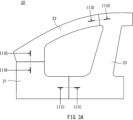
- FIG. 3A is a schematic diagram for explaining the method for manufacturing a structural member according to the first embodiment, and is a diagram showing a blank according to the first embodiment.
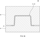
- FIG. 3B is a schematic diagram for explaining the manufacturing method of a structural member according to the first embodiment, and is a diagram showing a blank according to the first embodiment.
- FIG. 3C is a schematic diagram for explaining the manufacturing method of a structural member according to the first embodiment, and is a diagram showing a blank according to the first embodiment.
- FIG. 3A is a schematic diagram for explaining the method for manufacturing a structural member according to the first embodiment, and is a diagram showing a blank according to the first embodiment.
- FIG. 3B is a schematic diagram for explaining the manufacturing method of a structural member according to the first embodiment, and is a diagram showing a blank according to the first embodiment.
- FIG. 3D is a schematic diagram for explaining the manufacturing method of a structural member according to the first embodiment, and is a diagram showing a blank according to the first embodiment.
- FIG. 3E is a schematic diagram for explaining the manufacturing method of a structural member according to the first embodiment.
- FIG. 3F is a schematic diagram for explaining the manufacturing method of the structural member according to the first embodiment.
- FIG. 3G is a schematic diagram for explaining the manufacturing method of a structural member according to the first embodiment.
- FIG. 4 is a cross-sectional view of a blank according to the second embodiment.
- FIG. 5 is a cross-sectional view of a blank according to the third embodiment.
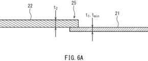
- FIG. 6A is a cross-sectional view of a blank according to a modification of each embodiment.
- FIG. 6B is another cross-sectional view of a blank according to a modification of each embodiment.
- FIG. 6C is another cross-sectional view of a blank according to a modification of each embodiment.
- FIG. 7 is a plan view of a structural member according to a modified example of each embodiment.
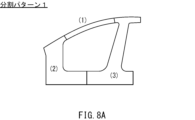
- FIG. 8A is a diagram showing a division pattern of a structural member in the first embodiment.
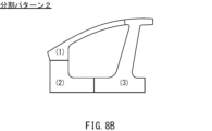
- FIG. 8B is a diagram showing another division pattern of the structural member in the first embodiment.
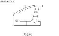
- FIG. 8C is a diagram showing still another division pattern of the structural member in the first embodiment.
- FIG. 8D is a diagram showing still another division pattern of the structural member in the first embodiment.
- FIG. 8E is a diagram showing still another division pattern of the structural member in the first embodiment.
- FIG. 8A is a diagram showing a division pattern of a structural member in the first embodiment.
- FIG. 8B is a diagram showing another division pattern of the structural member in the first embodiment.
- FIG. 8C is a diagram showing
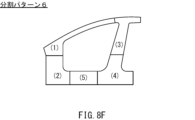
- FIG. 8F is a diagram showing yet another division pattern of the structural member in the first embodiment.
- FIG. 8G is a diagram showing yet another division pattern of the structural member in the first embodiment.
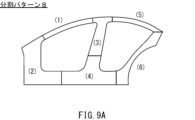
- FIG. 9A is a diagram showing a division pattern of a structural member in the second embodiment.
- FIG. 9B is a diagram showing another division pattern of the structural member in the second embodiment.
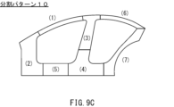
- FIG. 9C is a diagram showing yet another division pattern of the structural member in the second embodiment.
- FIG. 9D is a diagram showing yet another division pattern of the structural member in the second embodiment.
- the critical cooling rate V c90 has been used as an index of hardenability of steel materials.
- ⁇ is calculated by 2.7 ⁇ C + 0.4 ⁇ Si + Mn + 0.45 ⁇ Ni + 0.8 ⁇ Cr + 2 ⁇ Mo.
- ⁇ represents the degree of influence of each element on hardenability based on the amount of Mn. The larger ⁇ is, the smaller the critical cooling rate V c90 is, and the better the hardenability of the steel material is.
- the coefficient A corresponds to the transformation start time when only the influence of the elements is considered, and the larger the coefficient A, the better the hardenability of the steel material.
- the inventors further used the coefficient A to consider the appropriate arrangement of the steel material in the blank. As a result, the inventors completed a blank according to the embodiment.
- a blank for hot stamping includes a plurality of steel plates.
- the plurality of steel plates are arranged and joined to have an annular shape in a plan view of the blank.
- the plurality of steel plates include a first steel plate and a second steel plate.
- the first steel plate has a minimum plate thickness among the plurality of steel plates.
- the second steel plate has a plate thickness greater than that of the first steel plate.
- the value of coefficient A calculated by the following formula (1) using the chemical composition of the first steel plate is greater than the value of coefficient A calculated by the following formula (1) using the chemical composition of the second steel plate (first configuration).
- A 1.48 ⁇ (2.7 ⁇ C+0.4 ⁇ Si+Mn+0.45 ⁇ Ni+0.8 ⁇ Cr+2 ⁇ Mo) 3.42 (1)
- the element symbols are substituted with the contents (mass %) of the corresponding elements.
- the thin first steel plate will begin a phase transformation (diffusion transformation) from austenite to ferrite earlier than the thick second steel plate after the blank is heated for hot stamping.
- the coefficient A calculated based on the chemical composition of the first steel plate is greater than the coefficient A calculated based on the chemical composition of the second steel plate. That is, the first steel plate is made of a material that has a higher hardenability than the second steel plate, in other words, a material that starts diffusion transformation during cooling late.
- the start of diffusion transformation in the first steel plate is delayed, and the difference in transformation start time between the first steel plate and the second steel plate can be reduced.
- the blank is hot stamped, not only the relatively thick second steel plate but also the first steel plate having a minimum thickness can be well hardened, and the hardness of the structural member formed from the blank is easily uniformed.
- the first steel plate is well quenched, stress is offset by transformation plasticity and residual stress is reduced, which makes it possible to suppress the occurrence of twisting in annular structural components due to the concentration of residual stress, thereby reducing the deterioration of dimensional accuracy.
- the annular blank contains a first steel plate that is thinner than the second steel plate, the hardness of the structural component formed by hot stamping from the blank can be made uniform, and deterioration of dimensional accuracy can be suppressed. This makes it possible to improve the impact absorption performance (crash resistance performance) of annular structural components, particularly large and annular structural components.
- the manufacturing method for a structural member according to the embodiment includes a step of preparing a blank according to the first or second configuration, a step of heating the multiple steel plates contained in the blank to an austenite transformation completion temperature or higher, and a step of using a die to form the heated blank into a structural member that is annular in plan view and quenching it (third configuration).
- a structural member includes a member body.
- the member body has an annular shape in a plan view.
- the member body is formed by a plurality of steel plates joined to each other.
- the plurality of steel plates include a first steel plate having a minimum plate thickness and a second steel plate having a plate thickness greater than the plate thickness of the first steel plate.
- the value of coefficient A calculated by the following formula (1) using the chemical composition of the first steel plate is greater than the value of coefficient A calculated by the following formula (1) using the chemical composition of the second steel plate (fourth configuration).
- A 1.48 ⁇ (2.7 ⁇ C+0.4 ⁇ Si+Mn+0.45 ⁇ Ni+0.8 ⁇ Cr+2 ⁇ Mo) 3.42 (1)
- the element symbols are substituted with the contents (mass %) of the corresponding elements.
- the structural member according to the fourth configuration may be a door ring part of an automobile.
- the member body may include a front pillar, a center pillar, and a rocker connecting the front pillar and the center pillar (fifth configuration).
- First Embodiment [Structural Members] 1 is a diagram (plan view) of a structural member 10 according to the present embodiment, viewed from above in a state in which the structural member 10 is placed on a horizontal surface.
- the structural member 10 is used, for example, in the body of an automobile.
- the structural member 10 is typically a door ring part of an automobile. In the present embodiment, an example in which the structural member 10 is a door ring part will be described.
- the structural member 10 is a hot stamped member. That is, the structural member 10 is formed by hot stamping (hot press processing) a blank made of multiple steel plates.
- the structural member 10 includes a member body 11.
- the member body 11 has an annular shape in a plan view of the structural member 10.
- the member body 11 includes a front pillar 111, a center pillar 112, and a rocker 113.
- the center pillar 112 is disposed behind the front pillar 111.
- the center pillar 112 extends generally in the vertical direction of the vehicle body.
- the front pillar 111 extends toward the center pillar 112.
- the rocker 113 is disposed below the front pillar 111 and the center pillar 112.
- the rocker 113 connects the front pillar 111 and the center pillar 112.
- the member body 11 is formed from a plurality of steel plates 21, 22, and 23 joined together.
- the front pillar 111 is mainly composed of the steel plates 21 and 22.
- the center pillar 112 is mainly composed of the steel plate 23.
- the rocker 113 is composed of the steel plates 21 and 23.
- FIG. 2 is a cross-sectional view taken along line II-II of FIG. 1.
- FIG. 2 shows a cross-section of the structural member 10 cut along the thickness direction at the position of the steel plate 21.
- the steel plate 21 has an open cross-section.
- the steel plate 21 has, for example, a roughly hat-shaped shape in the cross-sectional view of the structural member 10. More specifically, the steel plate 21 includes a top plate 211, vertical walls 212 and 213, and flanges 214 and 215.
- the vertical wall 212 is disposed on the opposite side of the vertical wall 213 with respect to the top plate 211. In the cross-sectional view of the structural member 10, one end of the vertical walls 212 and 213 is connected by the top plate 211.
- the other end of the vertical walls 212 and 213 is connected to the flanges 214 and 215, respectively.
- the flanges 214 and 215 protrude from the vertical walls 212 and 213 to the outside of the structural member 10.
- the width W of the steel plate 21 at the position shown in FIG. 2, i.e., the width W of the lower part of the front pillar 111 (FIG. 1), may be 30 mm or more and 750 mm or less.
- the height H of the lower part of the front pillar 111 may be 25 mm or more and 150 mm or less.
- the width W is the distance from the R end of the corner part between the top plate 211 and the vertical wall 212 on the vertical wall 212 side to the R end of the corner part between the top plate 211 and the vertical wall 213 on the vertical wall 213 side in the cross section of the structural member 10.
- the height H is the distance from the top plate 211 to the flanges 214, 215 along the plate thickness direction of the top plate 211.
- the width W of the part of the steel plate 21 that corresponds to the locker 113 is, for example, 30 mm or more and 300 mm or less.
- the height of the part of the steel plate 21 that corresponds to the locker 113 may be 25 mm or more and 150 mm or less.
- the other steel plates 22, 23 (FIG. 1) also have an open cross section like the steel plate 21.
- the steel plates 22, 23 can also have, for example, a roughly hat shape in a cross section of the structural member 10.
- the width of the portion of the steel plate 22 that corresponds to the upper part of the front pillar 111 may be 15 mm or more and 300 mm or less.
- the height of the portion of the steel plate 22 that corresponds to the upper part of the front pillar 111 may be 10 mm or more and 150 mm or less.
- the width of the portion of the steel plate 23 that corresponds to the center pillar 112 may be 15 mm or more and 300 mm or less.
- the height of the portion of the steel plate 23 that corresponds to the center pillar 112 may be 10 mm or more and 150 mm or less.
- the size of the structural member 10, which is annular in plan view, is, for example, 1.0 m or more.
- the size of the structural member 10 may be, for example, 4.0 m or less.
- the size of the structural member 10 is the length of the line segment connecting any two points on the outer periphery of the structural member 10 that are farthest apart when the structural member 10 is placed on a horizontal surface and viewed vertically.
- the method for manufacturing the structural member 10 includes the steps of preparing a blank 20, heating the blank 20, and forming the heated blank 20 into the structural member 10.
- a blank 20 having a shape obtained by developing the structural member 10 is prepared.
- the blank 20 includes a plurality of steel plates 21, 22, and 23.
- the steel plates 21, 22, and 23 are arranged and joined to have an annular shape in a plan view of the blank 20.
- FIGS. 3B, 3C, and 3D are cross-sectional views of the blank 20 showing the joints of the steel plates 21, 22, and 23.
- FIGS. 3B, 3C, and 3D are cross-sectional views taken along lines IIIB-IIIB, IIIC-IIIC, and IIID-IIID in FIG. 3A, respectively.
- the steel plate 21 is butt-joined to each of the steel plates 22 and 23. That is, the end faces of the steel plate 21 are joined in a state where the end face of the steel plate 21 abuts against the end face of the steel plate 22, and the other end face of the steel plate 21 is joined in a state where the end face of the steel plate 21 abuts against the end face of the steel plate 23.
- the steel plate 22 is butt-joined to the steel plate 23 in addition to the steel plate 21.
- the end face of the steel plate 22 is joined to the end face of the steel plate 23 in a state where the end face of the steel plate 22 abuts against the end face of the steel plate 23.
- the steel plates 21, 22, and 23 are joined by, for example, laser welding.
- the blank 20 is a so-called tailor weld blank.
- the steel plate 21 has a plate thickness t1 .
- the steel plate 22 has a plate thickness t2 .
- the steel plate 23 has a plate thickness t3 .
- the plate thicknesses t2 and t3 of the steel plates 22 and 23 are greater than the plate thickness t1 of the steel plate 21. That is, the plate thickness t1 of the steel plate 21 is the minimum plate thickness tmin of the steel plates 21, 22, and 23.
- the plate thickness t2 of the steel plate 22 is greater than the plate thickness t3 of the steel plate 23. Therefore, the plate thickness t2 of the steel plate 22 is the maximum plate thickness tmax of the steel plates 21, 22, and 23.
- the steel plate 22 does not necessarily have to have the maximum plate thickness tmax of the steel plates 21, 22, and 23.
- the plate thickness t2 of the steel plate 22 may be equal to or less than the plate thickness t3 of the other steel plates 23.
- the minimum plate thickness t min and the maximum plate thickness t max of the steel plates 21, 22, and 23 satisfy, for example, t max - t min ⁇ 0.2 (mm).
- the plate thicknesses t min and t max may also satisfy t max - t min ⁇ 3.2 (mm).
- the plate thickness t min of the steel plate 21 is, for example, less than 1.4 mm.
- the plate thickness t min may be 0.8 mm or more.
- the maximum plate thickness t max is, for example, less than 4.0 mm.
- the plate thickness t max may be 1.4 mm or more.
- Steel sheets 21, 22, and 23 may have a known chemical composition as a steel sheet for hot stamping.
- the chemical composition of steel sheets 21, 22, and 23 contains, in mass%, C: 0.05-0.50%, Si: 0.020-1.000%, Mn: 0.20-2.50%, Ni: 0-0.50%, Cr: 0-0.50%, Mo: 0-0.5%, and B: 0.0005-0.0050%.
- each of the steel plates 21, 22, and 23 may further contain, in mass%, one or more elements selected from the group consisting of Cu: 0.005-3.000%, Co: 0.005-0.500%, Sn: 0.005-0.500%, Ca: 0.0005-0.0050%, Mg: 0.0005-0.0050%, REM: 0.0005-0.0050%, and Sb: 0.0005-0.0200%.
- the chemical composition of the steel plate 21 having the minimum plate thickness t min is different from the chemical compositions of the thicker steel plates 22 and 23.
- the value of coefficient A calculated by the following formula (1) using the chemical composition of the steel plate 21 is different from the coefficient A calculated by formula (1) for each of the steel plates 22 and 23 using their chemical compositions.
- A 1.48 ⁇ (2.7 ⁇ C+0.4 ⁇ Si+Mn+0.45 ⁇ Ni+0.8 ⁇ Cr+2 ⁇ Mo) 3.42 (1)
- the content (mass%) of the corresponding element is substituted for the element symbol in formula (1). That is, the coefficient A of the steel plate 21 is calculated by substituting the content (mass%) of each element in the chemical composition of the steel plate 21 for the corresponding element symbol in formula (1). Similarly, the coefficient A of the steel plate 22 is calculated by substituting the content (mass%) of each element in the chemical composition of the steel plate 22 for the corresponding element symbol in formula (1).
- the value of the coefficient A calculated by formula (1) using the chemical composition of the steel plate 21 is larger than the coefficient A calculated by formula (1) using the chemical composition of the steel plate 22.
- the coefficient A of the steel plate 22 is the smallest among the coefficients A calculated by formula (1) for the steel plates 22 and 23 other than the steel plate 21.
- a 1 -A 2 is preferably 0.10 or more, more preferably 0.20 or more.
- a 1 ⁇ A 2 may be, for example, less than or equal to 11.50.
- the coefficient A of the steel plate 23 is calculated by substituting the content (mass%) of each element in the chemical composition of the steel plate 23 into the corresponding element symbol in formula (1).
- the value of the coefficient A calculated by formula (1) using the chemical composition of the steel plate 23 is equal to or greater than the value of the coefficient A calculated by formula (1) using the chemical composition of the steel plate 22.
- the value of the coefficient A of the steel plate 23 is preferably smaller than the value of the coefficient A of the steel plate 21 having the minimum plate thickness t min . That is, among the multiple steel plates 21, 22, and 23 included in the blank 20, it is preferable that the coefficient A of the steel plate 21 having the minimum plate thickness t min is the largest.
- a 1 -A 3 is preferably 0.10 or more, more preferably 0.20 or more. Although not particularly limited, A 1 -A 3 may be 11.50 or less. However, the coefficient A3 of the steel plate 23 may be equal to or greater than the coefficient A1 of the steel plate 21 ( A1 - A3 ⁇ 0).
- the chemical composition of the steel plates 21, 22, and 23 contained in the blank 20 may be measured by a general analytical method.
- analytical test pieces may be taken from each of the steel plates 21, 22, and 23, and the test pieces may be measured using ICP-AES (Inductively Coupled Plasma-Atomic Emission Spectrometry) to obtain the chemical composition of the steel plates 21, 22, and 23.
- ICP-AES Inductively Coupled Plasma-Atomic Emission Spectrometry
- C may be measured using the combustion-infrared absorption method.
- the prepared blank 20 is formed into the structural member 10 (FIGS. 1 and 2) by hot stamping. During the hot stamping, the blank 20 is subjected to a heating step. Referring to FIG. 3E, in the heating step, the blank 20 is heated, for example, by a heating furnace 30.
- the multiple steel plates 21, 22, and 23 included in the blank 20 are heated to an austenite transformation completion temperature (A c3 point) or higher.
- the steel plates 21, 22, and 23 are heated, for example, to 900° C. or higher.
- the microstructures of the steel plates 21, 22, and 23 are transformed, for example, entirely or almost entirely into the austenite phase.
- the heated blank 20 is formed into an annular structural member 10 (Figs. 1 and 2) in a plan view using a die 40 and quenched.
- the blank 20 heated in the heating process is removed from the heating furnace 30 (Fig. 3E) and transported to the die 40.
- the die 40 is attached to a known press device.
- the die 40 includes, for example, a punch 41 and a die 42.
- the blank 20 is disposed between the punch 41 and the die 42.
- the die 42 approaches relatively to the punch 41.
- the blank 20 is clamped (pressed) by the punch 41 and the die 42 and formed into a shape that conforms to the forming surfaces of the punch 41 and the die 42.
- the blank 20 remains clamped between the punch 41 and the die 42.
- the blank 20 is cooled (quenched) by the die 40 and its microstructure is transformed into martensite. This allows the structural member 10 to be manufactured from the blank 20.
- the value of the coefficient A calculated by the above formula (1) using the chemical composition of the steel sheet 21 having the minimum sheet thickness t min is larger than the coefficient A calculated by the formula (1) using the chemical composition of the steel sheet 22.
- the value of the coefficient A calculated by the formula (1) using the chemical composition of the steel sheet 21 is preferably larger than the coefficient A calculated by the formula (1) using the chemical composition of the steel sheet 23.
- the value of the coefficient A calculated by the formula (1) using the chemical composition of the steel sheet 21 may be equal to or smaller than the coefficient A calculated by the formula (1) using the chemical composition of the steel sheet 23.
- the chemical composition of the steel sheets 21, 22, and 23 in the structural member 10 after hot stamping can be obtained by the same analytical method as that for the chemical composition of the steel sheets 21, 22, and 23 at the blank 20 stage.
- the variation in martensite fraction is, for example, 20% or less.
- the variation in martensite fraction is preferably 15% or less, and more preferably 10% or less.
- the variation in martensite fraction can be measured as follows. That is, in the cross section of the structural member 10 at the position of the steel plate 21 having the minimum plate thickness t min , 10 or more analysis samples (e.g., long side is about 10 mm in size) are cut out from positions 20 mm or more away from the end and 10 mm or more away from each other, and then each is mirror-polished and etched with LePeller's reagent so that the plate thickness direction becomes the observation surface.
- the image analysis method involves obtaining the maximum brightness value Lmax and the minimum brightness value Lmin from the image, determining the portion having pixels with brightness from Lmax-0.3 (Lmax-Lmin) to Lmax as a white region, and calculating the ratio of the number of pixels in the white region to the total number of pixels to measure the martensite fraction.
- This image analysis is performed on a total of 30 observation fields of each analysis sample to determine the martensite fraction, and the average value is taken as the martensite fraction of each analysis sample.
- the difference between the maximum and minimum values of the martensite fraction in 10 or more analysis samples is defined as the variation in the martensite fraction in the cross section of the structural member 10 at the position of the steel plate 21 having the minimum plate thickness t min .
- the area fraction of martensite obtained by image analysis i.e., the area fraction of the white area
- the area fraction of the white area may contain a few percent of the area fraction of retained austenite.
- the variation in the martensite fraction is calculated as a difference, the impact is minor.
- steel plate 21 can have a tensile strength of, for example, 0.5 GPa or more, and preferably has a tensile strength of 1.0 GPa or more.
- steel plates 22 and 23 (FIG. 1) can have a tensile strength of, for example, 0.5 GPa or more, and preferably has a tensile strength of 1.0 GPa or more.
- At least one of steel plates 21, 22, and 23 may have a tensile strength of 1.5 GPa or more after the forming process.
- the tensile strength of each of steel plates 21, 22, and 23 may be the same as or different from the tensile strength of the other steel plates.
- the coefficient A 1 of the steel plate 21 having the minimum plate thickness t min is greater than the coefficient A 2 of the thicker steel plate 22.
- the coefficients A 1 and A 2 correspond to the time (transformation start time) until the steel plates 21 and 22 start diffusion transformation, respectively, after the heating of the blank 20 for hot stamping from the heating furnace 30 is completed.
- the coefficients A 1 and A 2 are values corresponding to the transformation start time when only the influence of the elements is considered for each of the steel plates 21 and 22, without considering the influence of the plate thickness.
- the coefficient A1 is larger than the coefficient A2 , it means that the steel plate 21 is made of a material having a higher hardenability than the steel plate 22, in other words, a material in which the start of diffusion transformation during cooling is delayed.
- the coefficient A1 > the coefficient A2 as in this embodiment, the start of diffusion transformation in the steel plate 21 having the minimum plate thickness tmin can be delayed, and the difference in the transformation start time between the steel plates 21 and 22 can be reduced compared to when the coefficient A1 is equal to or smaller than the coefficient A2 .
- the steel plate 21 having the minimum plate thickness tmin can be well hardened, and the hardness of the structural member formed from the blank 20 is easily made uniform.
- the steel plate 21 is well hardened, stress is offset by transformation plasticity and the residual stress is reduced, so that the occurrence of twisting due to the concentration of residual stress in the annular structural member 10 can be suppressed. As a result, the deterioration of the dimensional accuracy of the structural member 10 can be reduced.
- the annular blank 20 contains a steel plate 21 that is thinner than the steel plate 22, the hardness of the structural member 10 formed by hot stamping from the blank 20 can be made uniform, and deterioration of dimensional accuracy can be suppressed. Therefore, the impact absorption performance (crash resistance performance) of the annular structural member 10, particularly a large and annular structural member 10, can be improved.
- the hardenability of the relatively thin steel plate 21 is improved, so that the hardness of the structural member 10 formed from the blank 20 can be made uniform. More specifically, even the steel plate 21 having the minimum plate thickness t min is well hardened, so that the variation in the martensite fraction in the steel plate 21 can be made 20% or less. As a result, for example, when a collision load is input to the structural member 10, deformation concentration is unlikely to occur, and the structural member 10 is more likely to exhibit high impact absorption performance. Therefore, even when an annular structural member 10 including a steel plate 21 having a small plate thickness, particularly a large and annular structural member 10, is formed from the blank 20, it is possible to reduce strength defects of the structural member 10 and improve the impact absorption performance of the structural member 10.
- hardenability-deficient parts i.e., hardness-deficient parts
- Second Embodiment Fig. 4 is a cross-sectional view of a blank 20A according to the second embodiment.
- Fig. 4 shows a joint between a steel plate 21 having a minimum plate thickness t min and a steel plate 22 having a larger plate thickness t 2.
- the blank 20A according to this embodiment has a configuration generally similar to that of the blank 20 according to the first embodiment, but differs from the blank 20 according to the first embodiment in that a coating 24 is provided on the steel plate 21.
- the steel plate 21 having the minimum plate thickness t min has one surface covered with the coating 24.
- the coating 24 is a substantially black coating.
- the coating 24 may be a carbon-based surface treatment coating (a coating containing carbon (C)).
- the coating 24 may contain, for example, carbon black.
- the coating 24 may further contain a metal oxide.
- the metal oxide may be, for example, one or more oxides selected from the group consisting of Zr oxide, Zn oxide, and Ti oxide.
- the coating 24 may also contain silica.
- the coating 24 may be, for example, a surface treatment coating described in WO 2022/215229. That is, the coating 24 may contain graphite or soot instead of or in addition to carbon black. Alternatively, the coating 24 may contain, for example, an acicular compound having a hexagonal crystal structure with an aspect ratio of 4 to 50.
- the compound having a hexagonal crystal structure is typically graphite (C), but may also be lanthanum silicate, magnesium diboride, beryllium oxide (beryllia), zinc oxide, ⁇ -quartz, goethite (NiS), wurtzite (ZnS), or the like.
- the blank 20A according to this embodiment is formed into an annular structural member 10 (FIGS. 1 and 2) by the same manufacturing method as in the first embodiment.
- the emissivity of the surface of the steel sheet 21 is increased by a substantially black coating 24 applied to the surface of the steel sheet 21.
- the surface of the steel sheet 21 covered with the coating 24 has an emissivity of 60% or more at a measurement temperature of 25° C. and a wavelength of 8.0 ⁇ m, for example.
- the steel sheet 21 can be quickly heated to a temperature in the austenite range to ensure a long high-temperature holding time of the steel sheet 21.
- the austenite crystal grains in the microstructure of the steel sheet 21 become coarse, and the diffusion transformation of the steel sheet 21 after the heating process is completed can be further delayed. Therefore, the steel sheet 21 can be quenched more satisfactorily.
- At least a portion of the coating 24 can remain on the surface of the steel sheet 21 after hot stamping.
- one surface of the steel plate 21 is coated with the coating 24.
- both surfaces of the steel plate 21 may be coated with the coating 24, which is substantially black.
- the coating 24 may or may not be provided on one or both surfaces of the other steel plates 22, 23.
- FIG. 5 is a cross-sectional view of a blank 20B according to a third embodiment.
- Fig. 5 shows a joint between a steel sheet 21 having a minimum sheet thickness tmin and a steel sheet 22 having a larger sheet thickness t2 .
- the blank 20B according to this embodiment has a configuration generally similar to that of the blank 20 according to the first embodiment, but differs from the blank 20 according to the first embodiment in that the steel sheets 21 and 22 are plated steel sheets.
- the steel plate 21 has a base steel plate 21a and an aluminum-based plating layer 21b.
- the aluminum-based plating layer 21b covers both surfaces of the base steel plate 21a.
- the aluminum-based plating layer 21b is provided over the entire or almost the entire surfaces of both surfaces of the base steel plate 21a.
- the steel plate 22 has a base steel plate 22a and an aluminum-based plating layer 22b.
- the aluminum-based plating layer 22b covers both surfaces of the base steel plate 22a.
- the aluminum-based plating layer 22b is provided over the entire or almost the entire surfaces of both surfaces of the base steel plate 22a.
- the sheet thickness t min of the steel plate 21 is the sheet thickness including the base steel plate 21a and the aluminum-based plating layer 21b.
- the sheet thickness t 2 of the steel plate 22 is the sheet thickness including the base steel plate 22a and the aluminum-based plating layer 22b.
- the chemical composition of the aluminum-based plating layers 21b, 22b is not particularly limited.
- a known aluminum-based plating layer (a plating layer whose main component is aluminum) can be used as the aluminum-based plating layers 21b, 22b.
- the aluminum-based plating layers 21b, 22b are, for example, Al-Si-based plating layers.
- the chemical compositions of the aluminum-based plating layers 21b, 22b may be the same or different.
- the adhesion weights W1, W2 may each be 20 g/m2 or more and 120 g/m2 or less .
- the adhesion weight W1 of the aluminum-based plating layer 21b is the average adhesion weight on both surfaces of the base steel sheet 21a.
- the adhesion weight W2 of the aluminum-based plating layer 22b is the average adhesion weight on both surfaces of the base steel sheet 22a.
- Each of the coating weights W1 and W2 is preferably 30 g/m 2 or more, and more preferably 35 g/m 2 or more.
- Each of the coating weights W1 and W2 is preferably 115 g/m 2 or less, and more preferably 100 g/m 2 or less.
- the coating weight W1 of the aluminum-based plating layer 21b in the steel sheet 21 having the minimum sheet thickness t min is less than the coating weight W2 of the aluminum-based plating layer 22b in the steel sheet 22 having the greater sheet thickness t 2.
- the difference between the coating weights W1 and W2: W2-W1, is, for example, 10 (g/m 2 ) or more.
- W2-W1 is preferably 20 (g/m 2 ) or more, and more preferably 30 (g/m 2 ) or more. W2-W1 may be 80 (g/m 2 ) or less. W2-W1 is preferably 70 (g/ m2 ) or less, and more preferably 60 (g/ m2 ) or less.
- the adhesion amounts W1 and W2 satisfy the relationship W2/W1>1.0.
- the adhesion amounts W1 and W2 preferably satisfy the relationship W2/W1 ⁇ 1.2, and more preferably W2/W1 ⁇ 1.5.
- the coefficients A1 and A2 are calculated using the chemical compositions of the base steel sheets 21a and 22a. That is, the coefficient A1 of the steel sheet 21 is calculated by substituting the content (mass%) of each element in the chemical composition of the base steel sheet 21a into the above-mentioned formula (1). Similarly, the coefficient A2 of the steel sheet 22 is calculated by substituting the content (mass%) of each element in the chemical composition of the base steel sheet 22a into the formula (1). In this embodiment, as in the first embodiment, the coefficient A1 of the steel sheet 21 is larger than the coefficient A2 of the steel sheet 22. The coefficient A2 of the steel sheet 22 is the smallest coefficient A among the coefficients A calculated by the formula (1) for each of the multiple steel sheets included in the blank 20B.
- the blank 20B according to this embodiment is formed into an annular structural member 10 (FIGS. 1 and 2) by the same manufacturing method as in the first embodiment.
- the adhesion weight W1 of the aluminum-based plating layer 21b of the steel sheet 21 having the minimum sheet thickness t min is smaller than the adhesion weight W2 of the aluminum-based plating layer 22b of the steel sheet 22 having the larger sheet thickness t 2.
- the temperature rise rate of the steel sheet 21 is significantly higher than that of the steel sheet 22.
- the aluminum-based plating layer 21b on the surface of the steel sheet 21 is relatively thin, when the blank 20B is heated, alloying of the aluminum-based plating layer 21b with the iron contained in the base steel sheet 21a progresses quickly to the surface of the steel sheet 21, and both surfaces of the steel sheet 21 change to black or a color close to black. That is, the emissivity of both surfaces of the steel sheet 21 increases during the heating process. Therefore, the steel sheet 21 can be quickly heated to the austenite temperature range, and the high-temperature holding time of the steel sheet 21 can be secured for a long time. As a result, the austenite grains in the microstructure of the steel sheet 21 become coarse, and the diffusion transformation of the steel sheet 21 after the heating process is completed can be further delayed. Therefore, the steel sheet 21 can be more satisfactorily quenched.
- the plating thickness K1 of the steel sheet 21 is smaller than the plating thickness K2 of the steel sheet 22.
- the difference between the plating thicknesses K1 and K2: K2-K1 is, for example, 7 ( ⁇ m) or more.
- K2-K1 may be 33 ( ⁇ m) or less.
- the plating thicknesses K1 and K2 can satisfy the relationship K2/K1>1.0.
- K2/K1 is preferably 1.2 or more, more preferably 1.5 or more.
- the steel sheet 23 may be a plated steel sheet having a base steel sheet and a plating layer like the steel sheets 21 and 22, or may be a steel sheet (bare material) without a plating layer on the surface.
- the plating layer may be an aluminum-based plating layer or a metal plating layer other than aluminum.
- the adhesion amount and thickness of the plating layer on the base steel sheet are not particularly limited.
- the coefficient A3 of the steel sheet 23 is calculated by substituting the content (mass%) of each element in the chemical composition of the base steel sheet into the above-mentioned formula (1).
- the chemical compositions of the steel sheets 21, 22, and 23 can be measured by the general analysis method described in the first embodiment. The analysis of the chemical composition of the steel sheets 21, 22, and 23 may be performed after removing the plating layer on the surface by mechanical grinding.
- the configuration of the blank 20B according to this embodiment can also be combined with the blanks 20 and 20A according to the first and second embodiments, respectively. That is, in each of the blanks 20 and 20A, the steel sheet 21 is a plated steel sheet having a base steel sheet 21a and an aluminum-based plating layer 21b, and the steel sheet 22 is a plated steel sheet having a base steel sheet 22a and an aluminum-based plating layer 22b, and the adhesion amount W1 of the aluminum-based plating layer 21b on the steel sheet 21 may be less than the adhesion amount W2 of the aluminum-based plating layer 22b on the steel sheet 22.
- the adhesion weight W1 of the aluminum-based plating layer 21b on the steel sheet 21 may be equal to or greater than the adhesion weight W2 of the aluminum-based plating layer 22b on the steel sheet 22.
- the plating layers of the steel sheets 21 and 22 may be metal plating layers other than aluminum, or the steel sheets 21 and 22 may be steel sheets (bare materials) that do not have a plating layer on their surface.
- each of the blanks 20, 20A, and 20B includes three steel plates 21, 22, and 23.
- the number of steel plates included in the blanks 20, 20A, and 20B is not limited to this.
- the blanks 20, 20A, and 20B may be composed of two steel plates 21 and 22, or may include four or more steel plates.
- the blanks 20, 20A, and 20B may include at least the steel plate 21 having the minimum plate thickness t min and the steel plate 22 having the plate thickness t 2 larger than the plate thickness t min .
- the blanks 20, 20A, 20B which are annular in plan view, may typically include three or more steel plates.
- the steel plate 21 is directly or indirectly joined to the steel plate 22.
- the arrangement of the multiple steel plates including the steel plates 21 and 22 is not particularly limited.
- the coefficient A1 of all the steel plates 21 is greater than the coefficient A2 of the steel plate 22.
- the coefficient A of the steel plates other than the steel plates 21, 22 is equal to or greater than the coefficient A2 of the steel plate 22.
- the steel plate 21 is butt-joined to each of the steel plates 22 and 23.
- the steel plate 22 is butt-joined to the steel plate 23.
- the steel plate 21 may be overlap-joined to at least one of the steel plates 22 and 23. That is, as shown in FIG. 6A, the end of the steel plate 21 may be overlapped on the end of the steel plate 22 and joined to the end of the steel plate 22 by, for example, spot welding or laser welding, so that the steel plates 21 and 22 form an overlap portion 25.
- spot welding or laser welding so that the steel plates 21 and 22 form an overlap portion 25.
- the end of the steel plate 21 may be overlapped on the end of the steel plate 23 and joined to the end of the steel plate 23 by, for example, spot welding or laser welding, so that the steel plates 21 and 23 form an overlap portion 25.
- the end of steel plate 22 may be joined to the end of steel plate 23 by, for example, spot welding or laser welding while overlapping the end of steel plate 23, so that steel plates 22 and 23 form an overlap portion 25.
- the joining method for adjacent steel plates may be butt joining or lap joining.
- each of the blanks 20, 20A, and 20B may each be a single layer or multiple layers.
- each of the multiple steel plates may be a single steel plate, or a plate material formed by overlapping multiple steel plates.
- the die 40 used for hot stamping the blanks 20, 20A, and 20B includes a punch 41 and a die 42.
- the configuration of the die 40 is not limited to the example described in the above embodiment.
- the die 40 may further include, for example, a pad and a blank holder.
- the main body 11 of the structural member 10 includes a front pillar 111, a center pillar 112, and a rocker 113.
- the member main body 11 can further include other components.
- the member main body 11 can further include a rear pillar 114.
- the structural member 10 according to the above embodiment is a door ring part having a single ring shape (single door ring part).
- the structural member shown in FIG. 7 is a door ring part having a double ring shape (double door ring part).
- the blank that serves as the material also has a double ring shape.
- Table 1 shows the types of steel sheets (materials) used in this analysis. For each material, Table 1 shows the content (mass%) of each element in the base material, the type of plating, and the coefficient A calculated using the above-mentioned formula (1).
- Figures 8A to 8G show the division pattern of the structural members.
- Figures 8A to 8G show the number of steel plates (materials) contained in the structural member, which is a single door ring part, and the positions of the joints between the steel plates in the structural member.
- each steel plate is given a number in parentheses.
- Example 1 the coefficient A value is maximum in the material (3) having the smallest plate thickness t min : 1.2 mm among the materials (1) to (3).
- the coefficient A 1 of the thinnest material (3) is significantly larger than the smallest coefficient A 2 in the other materials (1) and (2).
- the coefficient A 1 of the material (1) having the smallest plate thickness t min : 1.2 mm among the materials (1) to (3) is also significantly larger than the smallest coefficient A 2 in the other materials (2) and (3).
- the coefficient A value is maximum in the material (2) having the smallest plate thickness t min : 1.2 mm among the materials (1) to (3).
- the coefficient A 1 of the thinnest material (2) is also significantly larger than the smallest coefficient A 2 in the other materials (1) and (3).
- the coefficient A1 of the thinnest material is equal to or lower than the coefficients A of the other materials.
- the coefficient A corresponds to the transformation start time for each material when only the influence of the elements is considered, but the actual transformation start time for each material is also affected by the plate thickness, and becomes shorter as the plate thickness becomes smaller.
- the "phase transformation start time” in Table 2 is the shortest time until the phase transformation to ferrite starts after the blank is heated at a furnace temperature of 920°C for 5 minutes and 30 seconds and removed from the heating furnace (the time until the thinnest material starts phase transformation). As shown in Table 2, the phase transformation start time was longer in Examples 1 to 3 than in Comparative Examples 1 and 2.
- Example 3 and Comparative Example 2 which are the same conditions except for the material of the thinnest material (2), it can be seen that the phase transformation start time in Example 3 is slower than that in Comparative Example 2.
- the coefficient A 1 of the thinnest material (2) is larger than the smallest coefficient A 2 among the other materials (1) and (3), and the hardenability of the thinnest material is higher than the hardenability of the other materials.
- the coefficient A1 of the thinnest material (2) is equal to or less than the smallest coefficient A2 among the other materials (1) and (3), and the hardenability of the thinnest material is equal to or less than the hardenability of the other materials.
- Example 3 the hardenability of the thinnest material is made higher than that of the other materials, so that the phase transformation start time of the thinnest material is extended compared to Comparative Example 2, and the phase transformation start time of the thinnest material and the phase transformation start time of the relatively thick other materials are uniformed. Therefore, in Example 3, after the heating of the blank is completed, it becomes easier to start forming before the phase transformation to ferrite starts in the thinnest material, and it becomes easier to uniformly harden the structural member.
- the coefficient A1 of the material with the smallest plate thickness t min among the materials (1) to (4) is larger than the smallest coefficient A2 among the other relatively thick materials.
- the coefficient A1 of the material with the smallest plate thickness t min among the materials (1) to (4) is equal to or smaller than the smallest coefficient A2 among the other relatively thick materials.
- Example 6 When each Example is compared with the corresponding Comparative Example, it can be seen that the phase transformation start time is extended. For example, when Example 6 and Comparative Example 5, which are the same except for the material of the thinnest material (4), are compared, the phase transformation start time of Example 6 is delayed compared to Comparative Example 5.
- the coefficient A1 of the thinnest material (4) is larger than the smallest coefficient A2 among the other materials (1) to (3), and the hardenability of the thinnest material is higher than the hardenability of one or more other materials.
- Example 6 the coefficient A1 of the thinnest material (4) is equal to or smaller than the smallest coefficient A2 among the other materials (1) to ( 3 ), and the hardenability of the thinnest material is equal to or smaller than the hardenability of the other materials.
- the hardenability of the thinnest material is made higher than the hardenability of the other materials, so that the phase transformation start time of the thinnest material is extended compared to Comparative Example 5, and the phase transformation start time of the thinnest material and the phase transformation start time of the relatively thick other materials are uniformed. Therefore, in Example 6, after the heating of the blank was completed, forming was likely to begin before the phase transformation to ferrite began in the thinnest material, making it easier for the structural member to be quenched uniformly.
- Table 4 shows the analysis conditions and results for division patterns 5 to 7 shown in Figures 8E to 8G.
- the structural members are formed from five pieces of material (1) to (5).
- the coefficient A1 of the material having the smallest plate thickness tmin among the materials (1) to (5) is larger than the smallest coefficient A2 among the other relatively thick materials.
- the coefficient A1 of the material having the smallest plate thickness tmin among the materials (1) to (5) is equal to or smaller than the smallest coefficient A2 among the other relatively thick materials.
- Example 12 When each Example is compared with the corresponding Comparative Example, it can be seen that the phase transformation start time is extended. For example, when Example 12 and Comparative Example 8, which are the same except for the materials of the thinnest materials (1) and (4), are compared, the phase transformation start time of Example 12 is delayed compared to Comparative Example 8.
- the coefficient A1 of the thinnest materials (1) and (4) is larger than the smallest coefficient A2 among the other materials (2), (3), and (5), and the hardenability of the thinnest material is higher than the hardenability of one or more other materials.
- the coefficient A1 of the thinnest materials (1) and (4) is larger than all the coefficients A of the other materials (2), (3), and (5).
- Example 12 the coefficient A1 of the thinnest materials (1) and (4) is equal to or smaller than the smallest coefficient A2 among the other materials (2), (3), and (5), and the hardenability of the thinnest material is equal to or smaller than the hardenability of the other materials.
- the hardenability of the thinnest material was made higher than that of the other materials, so that the phase transformation start time of the thinnest material was extended compared to Comparative Example 8, and the phase transformation start time of the thinnest material and the phase transformation start time of the other relatively thick materials were made uniform. Therefore, in Example 12, after heating of the blank was completed, it became easier to start forming before the phase transformation to ferrite started in the thinnest material, and it became easier to uniformly harden the structural member.
- Example 13 Comparative Example 9 which are the same except for the materials of the thinnest materials (1), (3), and (5)
- the phase transformation start time is delayed in Example 13 compared to Comparative Example 9.
- the smallest coefficient A1 among the thinnest materials (1), (3), and (5) is larger than the smallest coefficient A2 among the other materials (2) and (4), and the hardenability of the thinnest material is higher than the hardenability of one or more other materials.
- all of the coefficients A of the thinnest materials (1), (3), and (5) are larger than the coefficients A of the other materials (2) and (4).
- Example 13 the smallest coefficient A1 among the thinnest materials (1), (3), and (5) is equal to or smaller than the smallest coefficient A2 among the other materials (2) and (4), and the hardenability of the thinnest material is equal to or smaller than the hardenability of the other materials.
- the hardenability of the thinnest material was made higher than that of the other materials, so that the phase transformation start time of the thinnest material was extended compared to Comparative Example 9, and the phase transformation start time of the thinnest material and the phase transformation start time of the other relatively thick materials were made uniform. Therefore, in Example 13, after heating of the blank was completed, it became easier to start forming before the phase transformation to ferrite started in the thinnest material, and it became easier to harden the structural member uniformly.
- Example 18 and Comparative Example 12 material (2) and material (5), material (3) and material (4), and material (4) and material (5) each form an overlap at their joints.
- material (2) and material (5), and material (3) and material (4) each form an overlap at their joints.
- the coefficient A1 of the material with the smallest thickness tmin among the materials (1) to (5) is larger than the smallest coefficient A2 among the other relatively thick materials.
- the coefficient A1 of the material with the smallest thickness tmin among the materials ( 1 ) to (5) is equal to or smaller than the smallest coefficient A2 among the other relatively thick materials.
- phase transformation start times of Examples 18 and 19 are slower than those of Comparative Examples 12 and 13. Therefore, it was confirmed that even when an overlapping portion exists in a blank, the phase transformation start times of each material in the blank can be made uniform by making the coefficient A1 of the thinnest material larger than the smallest coefficient A2 among the other materials.
- the steel plates used as materials were selected from those shown in Table 1.
- the division pattern of the structural members is as shown in Figures 9A to 9D.
- Figures 9A to 9D show the number of steel plates (materials) contained in the structural members that are double door ring parts, and the positions of the joints between the steel plates in the structural members.
- each steel plate used as material is given a number in parentheses.
- Table 6 shows the analysis conditions and results for division patterns 8 and 9 shown in Figures 9A and 9B.
- the structural member is formed from six pieces of material (1) to (6).
- the coefficient A1 of the minimum thickness tmin among the materials (1) to (6) is larger than the minimum coefficient A2 among the other relatively thick materials.
- the coefficient A1 of the minimum thickness tmin among the materials (1) to (6) is equal to or smaller than the minimum coefficient A2 among the other relatively thick materials.
- the minimum coefficient A1 among the materials (1) to (7) having the minimum plate thickness t min is larger than the minimum coefficient A2 among the other relatively thick materials.
- the minimum coefficient A1 among the materials ( 1 ) to (7) having the minimum plate thickness t min is equal to or smaller than the minimum coefficient A2 among the other relatively thick materials.
- Examples 14 and 16 in Table 8 are examples with the same conditions as Examples 14 and 16 shown in Table 4.
- Example 15A has the same division pattern and material combination as Example 15 shown in Table 4, but some of the materials form overlapping portions at the joints.
- Comparative Example 10A has the same division pattern and material combination as Comparative Example 10 shown in Table 4, but some of the materials form overlapping portions at the joints.
- material (1) and material (2), material (1) and material (3), material (2) and material (5), and material (4) and material (5) each form overlapping portions at their joints.
- Comparative Example 11 is a comparative example with the same conditions as Comparative Example 11 shown in Table 4.
- the variation in martensite fraction is the value obtained by subtracting the minimum martensite fraction (%) from the maximum martensite fraction (%) in the cross section of the structural member at the position of the material having the minimum plate thickness t min , as described in the above embodiment.
- the shape accuracy was evaluated based on how far apart the structural member was from the mating member at the overlapping portion of the structural member and mating member when the structural member was attached to another member, which was roughly hat-shaped in cross section.
- Table 8 cases where the distance from the surface of the mating member was within ⁇ 2.0 mm are marked with an O, cases where it was between ⁇ 2.0 mm and ⁇ 3.0 mm, and cases where it was over ⁇ 3.0 mm are marked with an X.
- door ring assembly parts were produced by spot welding door ring inner parts to each structural member (door ring outer part) of the examples and comparative examples shown in Table 8, and these were used as test specimens for partial structure evaluation. Then, the periphery of each test specimen was fixed with a restraining jig to reproduce the deformation during a vehicle collision, and a barrier was collided from the door ring outer part side (side of the vehicle body), and the maximum intrusion amount at this time was evaluated as impact absorption performance.
- Impact absorption performance was evaluated based on the impact absorption performance of the door ring outer part formed by joining each material after forming it by hot stamping, and compared with the impact absorption performance of the base.
- each example shown in Table 8 satisfies A 1 -A 2 >0, whereas each comparative example satisfies A 1 -A 2 ⁇ 0.
- the variation in martensite fraction exceeded 20%, whereas in examples 14, 15A, and 16, the variation in martensite fraction was 20% or less.
- the variation in martensite fraction was reduced to 15% or less.
- the shape accuracy was also better than that of comparative examples 10A and 11.
- Examples 14, 15A, and 16 where the variation in the martensite fraction was small, the impact absorption performance was improved compared to Comparative Examples 10A and 11.
- Examples 14 and 15A where the variation in the martensite fraction was 10% or less, impact absorption performance equal to or greater than that of the base was ensured.
- impact absorption performance equal to or greater than that of a structural component formed by joining the materials after press forming them individually was ensured.
- Structural member 11 Member body 20, 20A, 20B: Blank 21: Steel plate (first steel plate) 22: Steel plate (second steel plate) 23: Steel plate 40: Mold 111: Front pillar 112: Center pillar 113: Locker
Landscapes
- Engineering & Computer Science (AREA)
- Chemical & Material Sciences (AREA)
- Mechanical Engineering (AREA)
- Materials Engineering (AREA)
- Metallurgy (AREA)
- Organic Chemistry (AREA)
- Combustion & Propulsion (AREA)
- Transportation (AREA)
- Thermal Sciences (AREA)
- Crystallography & Structural Chemistry (AREA)
- Physics & Mathematics (AREA)
- Shaping Metal By Deep-Drawing, Or The Like (AREA)
- Heat Treatment Of Articles (AREA)
Abstract
ブランク(20,20A,20B)は、複数の鋼板を備える。複数の鋼板は、ブランク(20,20A,20B)の平面視で環状を有するように配置され、接合されている。複数の鋼板は、最小の板厚(tmin)を有する第1鋼板(21)と、第1鋼板(21)の板厚(tmin)よりも大きい板厚(t2)を有する第2鋼板(22)とを含む。第1鋼板(21)の化学組成を用いて式(1)で算出される係数Aの値は、第2鋼板(22)の化学組成を用いて式(1)で算出される係数Aの値よりも大きい。 A=1.48×(2.7×C+0.4×Si+Mn+0.45×Ni+0.8×Cr+2×Mo)3.42 (1)
Description
本開示は、ホットスタンプ用のブランクに関する。また、本開示は、そのブランクを用いた構造部材の製造方法、及び構造部材に関する。
自動車の車体等の構造物は、複数の構造部材によって形成されている。構造部材は、例えば、ブランクをプレス成形することによって製造される。構造部材は、高い強度及び良好な寸法精度を確保するため、ホットスタンプと称されるプレス成形方法によって製造されることがある。ホットスタンプは、鋼板であるブランクをオーステナイト域の温度まで加熱した後、金型によってブランクにプレス成形を施すとともに、金型内でブランクを保持して抜熱(急冷)することで焼入れする技術である。
特許文献1には、複数のブランクから自動車のボディサイド構造フレームを製造する方法が開示されている。特許文献1では、複数のブランクを接合して複合ブランクを形成し、複合ブランクをプレス成形することでボディサイド構造フレームを製造する。特許文献1には、複合ブランクを熱間成形(ホットスタンプ)することが記載されている。
特許文献2には、自動車用の側面構造を製造する方法が開示されている。側面構造は、内枠及び外枠を含む。特許文献2には、複数のブランクが溶接されて形成されたテーラードブランク(複合ブランク)をホットスタンプすることにより、内枠及び外枠の各々を製造することが記載されている。
近年、構造物の製造プロセスを簡素化するため、2つ以上の部材をブランクの段階から一体化することが検討されている。例えば、特許文献1には、平面視で環状(シングルリング形状)を有する複合ブランクをホットスタンプに供し、ピラーやロッカー等が一体化された環状のボディサイド構造フレームを成形することが開示されている。例えば、特許文献2には、平面視で環状(ダブルリング形状)を有する複合ブランクをホットスタンプに供し、ピラーやロッカー等が一体化された環状の内枠及び外枠を成形することが開示されている。しかしながら、複合ブランクに板厚が異なる複数の鋼板が含まれている場合、構造部材の性能が低下する可能性がある。具体的に説明すると、ホットスタンプに際し、ブランクは、例えば加熱炉でそのミクロ組織がオーステナイト化するまで加熱された後、金型によって構造部材に成形される。ただし、板厚が小さい鋼板は板厚が大きい鋼板と比較して冷却されやすいため、ブランクのうち板厚が小さい鋼板が配置されている部分では、ブランクが加熱炉から取り出されて成形が開始されるまでに冷却が進んで拡散変態が生じ、焼きが入りにくくなる可能性がある。これにより、構造部材において硬さの不均一が生じやすくなる。また、板厚が小さい鋼板には焼きが入りにくく応力が残留しやすいため、環状の構造部材にねじれが発生し、構造部材の寸法精度が悪化するおそれがある。硬さの不均一及び寸法精度の悪化が生じることにより、環状の構造部材において衝撃吸収性能(耐衝突性能)が低下する可能性がある。衝撃吸収性能の低下は、構造部材が大型になるほど顕著となる。
本開示は、他の鋼板と比較して板厚が小さい鋼板を含む環状の構造部材、特に大型且つ環状の構造部材を成形する際、構造部材の性能を向上可能なホットスタンプ用のブランクを提供することを課題とする。
本開示に係るホットスタンプ用のブランクは、複数の鋼板を備える。複数の鋼板は、ブランクの平面視で環状を有するように配置され、接合されている。複数の鋼板は、第1鋼板と、第2鋼板とを含む。第1鋼板は、複数の鋼板において最小の板厚を有する。第2鋼板は、第1鋼板の板厚よりも大きい板厚を有する。第1鋼板の化学組成を用いて以下の式(1)で算出される係数Aの値は、第2鋼板の化学組成を用いて以下の式(1)で算出される係数Aの値よりも大きい。
A=1.48×(2.7×C+0.4×Si+Mn+0.45×Ni+0.8×Cr+2×Mo)3.42 (1)
ただし、上記式(1)中の元素記号には、対応する元素の含有量(質量%)が代入される。
A=1.48×(2.7×C+0.4×Si+Mn+0.45×Ni+0.8×Cr+2×Mo)3.42 (1)
ただし、上記式(1)中の元素記号には、対応する元素の含有量(質量%)が代入される。
本開示に係るホットスタンプ用のブランクによれば、他の鋼板と比較して板厚が小さい鋼板を含む環状の構造部材、特に大型且つ環状の構造部材を成形する際、構造部材の性能を向上させることができる。
例えば「上野正勝,伊藤亀太郎,“GROSSMANNの式に代わる鋼の焼入性の新しい予測式”,鉄と鋼,一般社団法人 日本鉄鋼協会,第74年(1988)第6号,p.1073-1080」等に記載されているように、従来、鋼材の焼入れ性の指標として臨界冷却速度Vc90が使用されている。臨界冷却速度Vc90は、体積率で90%以上のマルテンサイト組織が得られる臨界冷却速度(℃/s)であり、logVc90=2.94-0.75βの式で表される。βは、2.7×C+0.4×Si+Mn+0.45×Ni+0.8×Cr+2×Moで算出される。βは、Mn量を基準に、焼入れ性に対する各元素の影響度を表したものである。βが大きいほど臨界冷却速度Vc90が小さくなり、鋼材の焼入れ性が良好となる。
焼入れ性に対する各元素の影響度を示すβと、鋼材の加熱を完了した後、拡散変態が開始するまでの時間(変態開始時間)との間には相関関係が存在する。本発明者等は、後述する実施例(表1)と同様のホットスタンプ用鋼板A,B,C,D(板厚1.2mm)を加熱炉で900℃に1分間保持した後、加熱炉から取り出して空冷し、相変態が開始するまでの時間(変態開始時間)を測定した。そして、測定された変態開始時間データを用いて回帰分析を行い、βを変態開始時間に変換する式:A=1.48×β3.42を構築した。本式で求められるAは、化学組成によって鋼材ごとに異なる係数(指標値)である。係数Aは、元素の影響のみを考慮したときの変態開始時間に相当し、係数Aが大きいほど焼入れ性が良い鋼材であることを意味する。本発明者等は、さらに、係数Aを利用し、ブランクにおける鋼材の適切な配置を検討した。その結果、本発明者等は、実施形態に係るブランクを完成させた。
実施形態に係るホットスタンプ用のブランクは、複数の鋼板を備える。複数の鋼板は、ブランクの平面視で環状を有するように配置され、接合されている。複数の鋼板は、第1鋼板と、第2鋼板とを含む。第1鋼板は、複数の鋼板において最小の板厚を有する。第2鋼板は、第1鋼板の板厚よりも大きい板厚を有する。第1鋼板の化学組成を用いて以下の式(1)で算出される係数Aの値は、第2鋼板の化学組成を用いて以下の式(1)で算出される係数Aの値よりも大きい(第1の構成)。
A=1.48×(2.7×C+0.4×Si+Mn+0.45×Ni+0.8×Cr+2×Mo)3.42 (1)
ただし、上記式(1)中の元素記号には、対応する元素の含有量(質量%)が代入される。
A=1.48×(2.7×C+0.4×Si+Mn+0.45×Ni+0.8×Cr+2×Mo)3.42 (1)
ただし、上記式(1)中の元素記号には、対応する元素の含有量(質量%)が代入される。
例えば、最小の板厚を有する第1鋼板と、第1鋼板よりも大きい板厚を有する第2鋼板とで材料の焼入れ性が同一である場合、薄肉の第1鋼板は、ホットスタンプのためのブランクの加熱を完了した後、厚肉の第2鋼板よりも早くオーステナイトからフェライトへの相変態(拡散変態)を開始する。しかしながら、第1の構成に係るブランクでは、第1鋼板についてその化学組成に基づき算出された係数Aは、第2鋼板についてその化学組成に基づき算出された係数Aよりも大きい。すなわち、第1鋼板が第2鋼板と比較して焼入れ性が高い材料、言い換えると冷却時の拡散変態の開始が遅い材料で構成されている。そのため、ブランクの加熱を完了した後、第1鋼板における拡散変態の開始が遅くなり、第1鋼板と第2鋼板との間の変態開始時間の差を小さくすることができる。その結果、ブランクをホットスタンプしたとき、比較的厚肉の第2鋼板だけでなく最小板厚の第1鋼板にも良好に焼入れを施すことができ、ブランクから成形される構造部材の硬さが均一化されやすくなる。また、第1鋼板に良好に焼きが入ることで変態塑性により応力が相殺され、残留応力が小さくなるため、環状の構造部材において、残留応力の集中に起因するねじれの発生を抑制することができ、結果として寸法精度の悪化を低減することができる。
このように、第1の構成では、環状のブランクが第2鋼板よりも薄肉の第1鋼板を含んでいるにもかかわらず、当該ブランクからホットスタンプで成形される構造部材の硬さを均一化することができ、寸法精度の悪化を抑制することができる。そのため、環状の構造部材、特に大型且つ環状の構造部材の衝撃吸収性能(耐衝突性能)を向上させることができる。
第1の構成に係るブランクにおいて、第1鋼板の板厚をtmin、複数の鋼板の板厚の中で最大の板厚をtmaxとしたとき、tmax-tmin≧0.2(mm)であってもよい(第2の構成)。
実施形態に係る構造部材の製造方法は、第1又は第2の構成に係るブランクを準備する工程と、ブランクに含まれる複数の鋼板をオーステナイト変態完了温度以上に加熱する工程と、金型を用い、加熱されたブランクを平面視で環状の構造部材に成形するとともに焼入れする工程とを備える(第3の構成)。
実施形態に係る構造部材は、部材本体を備える。部材本体は、平面視で環状を有する。部材本体は、互いに接合された複数の鋼板によって形成されている。複数の鋼板は、最小の板厚を有する第1鋼板と、第1鋼板の板厚よりも大きい板厚を有する第2鋼板とを含む。第1鋼板の化学組成を用いて以下の式(1)で算出される係数Aの値は、第2鋼板の化学組成を用いて以下の式(1)で算出される係数Aの値よりも大きい(第4の構成)。
A=1.48×(2.7×C+0.4×Si+Mn+0.45×Ni+0.8×Cr+2×Mo)3.42 (1)
ただし、上記式(1)中の元素記号には、対応する元素の含有量(質量%)が代入される。
A=1.48×(2.7×C+0.4×Si+Mn+0.45×Ni+0.8×Cr+2×Mo)3.42 (1)
ただし、上記式(1)中の元素記号には、対応する元素の含有量(質量%)が代入される。
第4の構成に係る構造部材は、自動車のドアリング部品であってもよい。この場合、部材本体は、フロントピラーと、センターピラーと、フロントピラーとセンターピラーとを接続するロッカーとを含むことができる(第5の構成)。
以下、本開示の実施形態について、図面を参照しつつ説明する。各図において同一又は相当の構成については同一符号を付し、同じ説明を繰り返さない。
<第1実施形態>
[構造部材]
図1は、本実施形態に係る構造部材10を水平面に載置した状態で上方から見た図(平面図)である。構造部材10は、例えば自動車の車体に用いられる。構造部材10は、典型的には自動車のドアリング部品である。本実施形態では、構造部材10がドアリング部品である例について説明する。
[構造部材]
図1は、本実施形態に係る構造部材10を水平面に載置した状態で上方から見た図(平面図)である。構造部材10は、例えば自動車の車体に用いられる。構造部材10は、典型的には自動車のドアリング部品である。本実施形態では、構造部材10がドアリング部品である例について説明する。
構造部材10は、ホットスタンプ部材である。すなわち、構造部材10は、複数の鋼板からなるブランクをホットスタンプ(熱間プレス加工)することによって形成されたものである。構造部材10は、部材本体11を含む。部材本体11は、構造部材10の平面視で環状を有する。部材本体11は、フロントピラー111と、センターピラー112と、ロッカー113とを含む。構造部材10が自動車の車体に組み付けられたとき、センターピラー112は、フロントピラー111の後方に配置される。センターピラー112は、概ね車体の上下方向に延在する。フロントピラー111は、センターピラー112に向かって延在する。構造部材10が自動車の車体に組み付けられたとき、ロッカー113は、フロントピラー111及びセンターピラー112の下方に配置される。ロッカー113は、フロントピラー111とセンターピラー112とを接続する。
本実施形態において、部材本体11は、互いに接合された複数の鋼板21,22,23によって形成されている。図1の例では、フロントピラー111は、主に鋼板21,22によって構成されている。センターピラー112は、主に鋼板23によって構成されている。ロッカー113は、鋼板21,23によって構成されている。
図2は、図1のII-II断面図である。図2では、構造部材10を鋼板21の位置でその板厚方向に沿って切断した断面を示す。図2に示すように、鋼板21は、開断面を有している。鋼板21は、構造部材10の断面視で例えば概略ハット状を有する。より具体的には、鋼板21は、天板211と、縦壁212,213と、フランジ214,215とを含む。縦壁212は、天板211に対して縦壁213の反対側に配置されている。構造部材10の断面視で、縦壁212,213の一端部は天板211によって接続されている。構造部材10の断面視で、縦壁212,213の他端部には、それぞれフランジ214,215が接続されている。フランジ214,215は、それぞれ縦壁212,213から構造部材10の外側に突出している。
構造部材10において、図2に示す位置での鋼板21の幅W、つまりフロントピラー111(図1)の下部の幅Wは、30mm以上750mm以下であってもよい。フロントピラー111の下部の高さHは、25mm以上150mm以下であってもよい。幅Wは、構造部材10の断面において、天板211と縦壁212との間のコーナー部の縦壁212側のR止まりから、天板211と縦壁213との間のコーナー部の縦壁213側のR止まりまでの距離である。高さHは、天板211からフランジ214,215までの天板211の板厚方向に沿った距離である。鋼板21のうちロッカー113(図1)に相当する部分の幅Wは、例えば30mm以上300mm以下である。鋼板21のうちロッカー113に相当する部分の高さは、25mm以上150mm以下であってもよい。
図示を省略するが、他の鋼板22,23(図1)も鋼板21と同様に開断面を有する。鋼板22,23も、構造部材10の断面視で例えば概略ハット状を有することができる。鋼板22のうちフロントピラー111の上部に相当する部分の幅は、15mm以上300mm以下であってもよい。鋼板22のうちフロントピラー111の上部に相当する部分の高さは、10mm以上150mm以下であってもよい。鋼板23のうちセンターピラー112に相当する部分の幅は、15mm以上300mm以下であってもよい。鋼板23のうちセンターピラー112に相当する部分の高さは、10mm以上150mm以下であってもよい。
平面視で環状の構造部材10の大きさは、例えば1.0m以上である。構造部材10の大きさは、例えば4.0m以下であってもよい。構造部材10の大きさとは、構造部材10を水平面に載置した状態で鉛直方向に沿って見たとき、構造部材10の外周上の任意の二点のうち最も距離が遠くなる二点を結ぶ線分の長さである。
[構造部材の製造方法]
以下、構造部材10の製造方法について、図3A~図3Gを参照しつつ説明する。本実施形態に係る構造部材10の製造方法は、ブランク20を準備する工程と、ブランク20を加熱する工程と、加熱されたブランク20を構造部材10に成形する工程とを含む。
以下、構造部材10の製造方法について、図3A~図3Gを参照しつつ説明する。本実施形態に係る構造部材10の製造方法は、ブランク20を準備する工程と、ブランク20を加熱する工程と、加熱されたブランク20を構造部材10に成形する工程とを含む。
(準備工程)
図3Aに示すように、準備工程では、構造部材10を展開した形状を有するブランク20を準備する。ブランク20は、複数の鋼板21,22,23を含む。鋼板21,22,23は、ブランク20の平面視で環状を有するように配置され、接合されている。
図3Aに示すように、準備工程では、構造部材10を展開した形状を有するブランク20を準備する。ブランク20は、複数の鋼板21,22,23を含む。鋼板21,22,23は、ブランク20の平面視で環状を有するように配置され、接合されている。
図3B、図3C、及び図3Dは、鋼板21,22,23の接合部を示すブランク20の断面図である。図3B、図3C、及び図3Dは、それぞれ、図3AのIIIB-IIIB断面図、IIIC-IIIC断面図、及びIIID-IIID断面図である。図3B及び図3Cを参照して、鋼板21は、鋼板22,23の各々に対して突合せ接合されている。すなわち、鋼板21の端面が鋼板22の端面に当接した状態でこれらの端面が接合され、鋼板21の他の端面が鋼板23の端面に当接した状態でこれらの端面が接合されている。図3Dを参照して、鋼板22は、鋼板21に加え、鋼板23に対して突合せ接合されている。鋼板22の端面は、鋼板23の端面に当接した状態で当該端面に接合されている。鋼板21,22,23は、例えばレーザー溶接によって接合される。本実施形態において、ブランク20はいわゆるテーラーウェルドブランクである。
図3B~図3Dを参照して、鋼板21は、板厚t1を有する。鋼板22は、板厚t2を有する。鋼板23は、板厚t3を有する。鋼板22,23の板厚t2,t3は、鋼板21の板厚t1よりも大きい。すなわち、鋼板21の板厚t1は、鋼板21,22,23において最小の板厚tminである。本実施形態の例では、鋼板22の板厚t2が鋼板23の板厚t3よりも大きい。したがって、鋼板22の板厚t2は、鋼板21,22,23において最大の板厚tmaxである。ただし、鋼板22は、必ずしも鋼板21,22,23において最大の板厚tmaxを有しなくてもよい。鋼板22の板厚t2は、他の鋼板23の板厚t3以下であってもよい。
鋼板21,22,23において最小の板厚tmin及び最大の板厚tmaxは、例えばtmax-tmin≧0.2(mm)を満たす。板厚tmin,tmaxは、tmax-tmin≦3.2(mm)を満たしていてもよい。鋼板21の板厚tminは、例えば1.4mm未満である。板厚tminは、0.8mm以上であってもよい。最大の板厚tmaxは、例えば4.0mm未満である。板厚tmaxは、1.4mm以上であってもよい。
鋼板21,22,23は、ホットスタンプ用の鋼板として公知の化学組成を有していてもよい。例えば、鋼板21,22,23の化学組成は、それぞれ、質量%で、C:0.05~0.50%、Si:0.020~1.000%、Mn:0.20~2.50%、Ni:0~0.50%、Cr:0~0.50%、Mo:0~0.5%、及びB:0.0005~0.0050%を含有する。鋼板21,22,23の各化学組成は、さらに、質量%で、Cu:0.005~3.000%、Co:0.005~0.500%、Sn:0.005~0.500%、Ca:0.0005~0.0050%、Mg:0.0005~0.0050%、REM:0.0005~0.0050%、及びSb:0.0005~0.0200%からなる群から選択される一種以上を含有していてもよい。
鋼板21,22,23において、最小の板厚tminを有する鋼板21の化学組成は、より厚肉の鋼板22,23の化学組成と異なる。鋼板21の化学組成を用いて以下の式(1)で算出される係数Aの値は、鋼板22,23の各々についてその化学組成を用いて式(1)で算出される係数Aと異なる。
A=1.48×(2.7×C+0.4×Si+Mn+0.45×Ni+0.8×Cr+2×Mo)3.42 (1)
A=1.48×(2.7×C+0.4×Si+Mn+0.45×Ni+0.8×Cr+2×Mo)3.42 (1)
式(1)中の元素記号には、対応する元素の含有量(質量%)が代入される。すなわち、鋼板21の係数Aは、鋼板21の化学組成における各元素の含有量(質量%)を式(1)中の対応する元素記号に代入して算出される。同様に、鋼板22の係数Aは、鋼板22の化学組成における各元素の含有量(質量%)を式(1)中の対応する元素記号に代入して算出される。鋼板21の化学組成を用いて式(1)で算出される係数Aの値は、鋼板22の化学組成を用いて式(1)で算出される係数Aよりも大きい。鋼板22の係数Aは、鋼板21以外の鋼板22,23について式(1)で算出される係数Aの中で最小のものである。鋼板21の係数AをA1、鋼板22の係数AをA2としたとき、A1-A2は、好ましくは0.10以上であり、より好ましくは0.20以上である。A1-A2は、例えば11.50以下であってもよい。
鋼板23の係数Aは、鋼板23の化学組成における各元素の含有量(質量%)を式(1)中の対応する元素記号に代入して算出される。鋼板23の化学組成を用いて式(1)で算出される係数Aの値は、鋼板22の化学組成を用いて式(1)で算出される係数Aの値以上である。鋼板23の係数Aの値は、好ましくは、最小の板厚tminを有する鋼板21の係数Aの値よりも小さい。すなわち、ブランク20に含まれる複数の鋼板21,22,23の中で、最小の板厚tminを有する鋼板21の係数Aが最大であることが好ましい。鋼板21の係数AをA1、鋼板23の係数AをA3としたとき、A1-A3は、好ましくは0.10以上であり、より好ましくは0.20以上である。特に限定されるものではないが、A1-A3は11.50以下であってもよい。しかしながら、鋼板23の係数A3は、鋼板21の係数A1以上(A1-A3≦0)であってもよい。
ブランク20に含まれる鋼板21,22,23の化学組成は、一般的な分析方法によって測定すればよい。例えば、鋼板21,22,23の各々から分析用の試験片を採取し、ICP-AES(Inductively Coupled Plasma-Atomic Emission Spectrometry)を用いてその試験片を測定することで、鋼板21,22,23の化学組成を得ることができる。分析用の各試験片において、Cは燃焼-赤外線吸収法を用いて測定すればよい。
(加熱工程)
準備されたブランク20は、ホットスタンプ(熱間プレス加工)によって構造部材10(図1及び図2)に成形される。ホットスタンプに際し、ブランク20は加熱工程に供される。図3Eを参照して、加熱工程では、例えば加熱炉30によってブランク20が加熱される。ブランク20に含まれる複数の鋼板21,22,23は、オーステナイト変態完了温度(Ac3点)以上に加熱される。鋼板21,22,23は、例えば900℃以上に加熱される。これにより、鋼板21,22,23のミクロ組織が例えば全て又はほぼオーステナイト相に変態する。
準備されたブランク20は、ホットスタンプ(熱間プレス加工)によって構造部材10(図1及び図2)に成形される。ホットスタンプに際し、ブランク20は加熱工程に供される。図3Eを参照して、加熱工程では、例えば加熱炉30によってブランク20が加熱される。ブランク20に含まれる複数の鋼板21,22,23は、オーステナイト変態完了温度(Ac3点)以上に加熱される。鋼板21,22,23は、例えば900℃以上に加熱される。これにより、鋼板21,22,23のミクロ組織が例えば全て又はほぼオーステナイト相に変態する。
(成形工程)
図3Fを参照して、成形工程では、金型40を用い、加熱されたブランク20を平面視で環状の構造部材10(図1及び図2)に成形するとともに焼入れする。加熱工程によって加熱されたブランク20は加熱炉30(図3E)から取り出され、金型40に搬送される。金型40は、公知のプレス装置に取り付けられている。金型40は、例えば、パンチ41及びダイ42を含む。ブランク20は、パンチ41とダイ42との間に配置される。
図3Fを参照して、成形工程では、金型40を用い、加熱されたブランク20を平面視で環状の構造部材10(図1及び図2)に成形するとともに焼入れする。加熱工程によって加熱されたブランク20は加熱炉30(図3E)から取り出され、金型40に搬送される。金型40は、公知のプレス装置に取り付けられている。金型40は、例えば、パンチ41及びダイ42を含む。ブランク20は、パンチ41とダイ42との間に配置される。
図3Gを参照して、ブランク20がパンチ41とダイ42との間に配置された後、ダイ42がパンチ41に対して相対的に接近する。ブランク20は、パンチ41及びダイ42によって挟持(プレス)され、パンチ41及びダイ42の成形面に沿った形状に成形される。ブランク20は、パンチ41及びダイ42によって挟持されたまま保持される。ブランク20は金型40によって抜熱(急冷)され、そのミクロ組織がマルテンサイトに変態する。これにより、ブランク20から構造部材10を製造することができる。
再度図1を参照して、鋼板21,22,23の化学組成は、ホットスタンプの前後で変化しない。そのため、構造部材10において、最小の板厚tminを有する鋼板21の化学組成を用いて上述した式(1)で算出される係数Aの値は、鋼板22の化学組成を用いて式(1)で算出される係数Aよりも大きい。鋼板21の化学組成を用いて式(1)で算出される係数Aの値は、好ましくは、鋼板23の化学組成を用いて式(1)で算出される係数Aよりも大きい。ただし、鋼板21の化学組成を用いて式(1)で算出される係数Aの値は、鋼板23の化学組成を用いて式(1)で算出される係数A以下であってもよい。
ホットスタンプ後の構造部材10における鋼板21,22,23の化学組成は、ブランク20の段階での鋼板21,22,23の化学組成と同様の分析方法によって得ることができる。
図2を参照して、最小の板厚tminを有する鋼板21の位置での構造部材10の断面において、最大のマルテンサイト分率(%)から最小のマルテンサイト分率(%)を減じた値をマルテンサイト分率のばらつきとしたとき、マルテンサイト分率のばらつきは例えば20%以下である。マルテンサイト分率のばらつきは、好ましくは15%以下であり、より好ましくは10%以下である。マルテンサイト分率のばらつきは、次のようにして測定することができる。すなわち、最小の板厚tminを有する鋼板21の位置での構造部材10の断面で、端部から20mm以上離れ、且つ、各々が10mm以上離れた位置から10個以上の分析サンプル(例えば長辺側が10mm程度の大きさ)を切り出した後、板厚方向が観察面となるように、各々を鏡面研磨し、且つレペラー試薬でエッチングする。そして、鋼板表面から板厚の1/4深さ(鋼板表面から板厚の1/8深さ~鋼板表面から板厚の3/8深さまでの領域)について、光学顕微鏡を用いて倍率1000倍の1視野2,400μm2以上の組織写真を30視野撮影し、得られた組織写真に対して画像解析を行う。
画像解析手法としては、画像の最大明度値Lmaxと最小明度値Lminとを画像から取得し、明度がLmax-0.3(Lmax-Lmin)からLmaxまでの画素を持つ部分を白色領域とし、白色領域の画素数が全体の画素数に占める割合を算出することで、マルテンサイト分率を測定する。各々の分析サンプルの合計30か所の観察視野について、このような画像解析を行ってマルテンサイト分率を求め、その平均値をもって各分析サンプルのマルテンサイト分率とする。さらに、10個以上の分析サンプルにおけるマルテンサイト分率の最大値と最小値の差を、最小の板厚tminを有する鋼板21の位置での構造部材10の断面におけるマルテンサイト分率のばらつきと定義する。構造部材10において最小の板厚tminを有する鋼板が複数存在する場合は、それぞれの鋼板でこのような分析を行ってマルテンサイト分率を求め、これらの鋼板の中で最大のマルテンサイト分率のばらつきを構造部材10におけるマルテンサイト分率のばらつきとする。
なお、鋼板によっては、画像解析で得られるマルテンサイトの面積率、すなわち白色領域の面積率に残留オーステナイトの面積率が数%含まれる場合がある。しかしながら、マルテンサイト分率のばらつきは差分で計算されるため、その影響は軽微である。
成形工程(ホットスタンプ)後において、鋼板21は、例えば0.5GPa以上の引張強さを有することができ、好ましくは1.0GPa以上の引張強さを有する。同様に、成形工程(ホットスタンプ)後において、鋼板22,23(図1)は、例えば0.5GPa以上の引張強さを有することができ、好ましくは1.0GPa以上の引張強さを有する。鋼板21,22,23のうち少なくとも1枚は、成形工程後において1.5GPa以上の引張強さを有していてもよい。鋼板21,22,23のそれぞれの引張強さは、他の鋼板の引張強さと同一であってもよいし、異なっていてもよい。
[効果]
本実施形態に係るブランク20では、最小の板厚tminを有する鋼板21の係数A1がより厚肉の鋼板22の係数A2よりも大きい。係数A1,A2は、鋼板21,22のそれぞれの化学組成に基づき、式(1):A=1.48×(2.7×C+0.4×Si+Mn+0.45×Ni+0.8×Cr+2×Mo)3.42を計算することで得られる値である。係数A1,A2は、加熱炉30からホットスタンプのためのブランク20の加熱を完了した後、鋼板21,22がそれぞれ拡散変態を開始するまでの時間(変態開始時間)に相当する。ただし、係数A1,A2は、鋼板21,22の各々について板厚の影響を考慮せず、元素の影響のみを考慮した場合の変態開始時間に相当する値である。係数A1が係数A2よりも大きい場合、鋼板21が鋼板22と比較して焼入れ性が高い材料、言い換えると冷却時の拡散変態の開始が遅い材料で構成されていることを意味する。本実施形態のように係数A1>係数A2とすることにより、最小板厚tminを有する鋼板21における拡散変態の開始を遅らせることができ、係数A1が係数A2以下である場合と比較して鋼板21,22の間の変態開始時間の差を小さくすることができる。そのため、ブランク20をホットスタンプしたとき、比較的厚肉の鋼板22だけでなく最小板厚tminの鋼板21にも良好に焼入れを施すことができ、ブランク20から成形される構造部材の硬さが均一化されやすくなる。また、鋼板21に良好に焼きが入ることで変態塑性により応力が相殺され、残留応力が小さくなるため、環状の構造部材10において、残留応力の集中に起因するねじれの発生を抑制することができる。その結果、構造部材10の寸法精度の悪化を低減することができる。
本実施形態に係るブランク20では、最小の板厚tminを有する鋼板21の係数A1がより厚肉の鋼板22の係数A2よりも大きい。係数A1,A2は、鋼板21,22のそれぞれの化学組成に基づき、式(1):A=1.48×(2.7×C+0.4×Si+Mn+0.45×Ni+0.8×Cr+2×Mo)3.42を計算することで得られる値である。係数A1,A2は、加熱炉30からホットスタンプのためのブランク20の加熱を完了した後、鋼板21,22がそれぞれ拡散変態を開始するまでの時間(変態開始時間)に相当する。ただし、係数A1,A2は、鋼板21,22の各々について板厚の影響を考慮せず、元素の影響のみを考慮した場合の変態開始時間に相当する値である。係数A1が係数A2よりも大きい場合、鋼板21が鋼板22と比較して焼入れ性が高い材料、言い換えると冷却時の拡散変態の開始が遅い材料で構成されていることを意味する。本実施形態のように係数A1>係数A2とすることにより、最小板厚tminを有する鋼板21における拡散変態の開始を遅らせることができ、係数A1が係数A2以下である場合と比較して鋼板21,22の間の変態開始時間の差を小さくすることができる。そのため、ブランク20をホットスタンプしたとき、比較的厚肉の鋼板22だけでなく最小板厚tminの鋼板21にも良好に焼入れを施すことができ、ブランク20から成形される構造部材の硬さが均一化されやすくなる。また、鋼板21に良好に焼きが入ることで変態塑性により応力が相殺され、残留応力が小さくなるため、環状の構造部材10において、残留応力の集中に起因するねじれの発生を抑制することができる。その結果、構造部材10の寸法精度の悪化を低減することができる。
このように、本実施形態では、環状のブランク20が鋼板22よりも薄肉の鋼板21を含んでいるにもかかわらず、ブランク20からホットスタンプで成形される構造部材10の硬さを均一化することができ、寸法精度の悪化を抑制することができる。そのため、環状の構造部材10、特に大型且つ環状の構造部材10の衝撃吸収性能(耐衝突性能)を向上させることができる。
本実施形態では、比較的薄肉の鋼板21の焼入れ性を向上させているため、ブランク20から成形された構造部材10の硬さを均一化することができる。より具体的には、最小の板厚tminを有する鋼板21にも良好に焼きが入るため、鋼板21におけるマルテンサイト分率のばらつきを20%以下とすることができる。これにより、例えば構造部材10に対して衝突荷重が入力されたときに変形集中が生じにくくなり、構造部材10が高い衝撃吸収性能を発揮しやすくなる。したがって、板厚が小さい鋼板21を含む環状の構造部材10、特に大型且つ環状の構造部材10をブランク20から成形する場合であっても、構造部材10の強度不良を低減することができ、構造部材10の衝撃吸収性能を向上させることができる。
マルテンサイト分率のばらつきが小さいほど、構造部材10内での機械特性の不均一が少なく、構造部材10の機能の観点で好ましい。一方、マルテンサイト分率のばらつきが大きい場合は、構造部材10内において焼入れ性不足部、つまり硬度不足部が偏在していることを表しており、構造部材10の衝突変形時には硬度不足部に変形が集中しやすくなるため、構造部材10の機能が低下する。
<第2実施形態>
図4は、第2実施形態に係るブランク20Aの断面図である。図4では、最小の板厚tminを有する鋼板21と、より大きい板厚t2を有する鋼板22との接合部を示している。本実施形態に係るブランク20Aは、第1実施形態に係るブランク20と概ね同様の構成を有するが、鋼板21に皮膜24が設けられている点で第1実施形態に係るブランク20と異なる。図4の例において、最小の板厚tminを有する鋼板21は、その一方の表面が皮膜24によって被覆されている。
図4は、第2実施形態に係るブランク20Aの断面図である。図4では、最小の板厚tminを有する鋼板21と、より大きい板厚t2を有する鋼板22との接合部を示している。本実施形態に係るブランク20Aは、第1実施形態に係るブランク20と概ね同様の構成を有するが、鋼板21に皮膜24が設けられている点で第1実施形態に係るブランク20と異なる。図4の例において、最小の板厚tminを有する鋼板21は、その一方の表面が皮膜24によって被覆されている。
皮膜24は、実質的に黒色の皮膜である。例えば、皮膜24の表面からの明度L*値(JIS Z8781-4(2013)に規定されるCIE 1976 明度指数L*)が60以下である場合、皮膜24は黒色であると判断することができる。皮膜24は、炭素系の表面処理皮膜(炭素(C)を含有する皮膜)であってもよい。
皮膜24は、例えばカーボンブラックを含有することができる。皮膜24は、さらに金属酸化物を含有することができる。金属酸化物は、例えば、Zr酸化物、Zn酸化物、及びTi酸化物からなる群より選択される1種以上の酸化物である。皮膜24は、シリカを含有していてもよい。
皮膜24として、例えば、国際公開第2022/215229号に記載された表面処理皮膜を使用することができる。すなわち、皮膜24は、カーボンブラックに代えて又は加えて、黒鉛又はすす等を含有することができる。あるいは、皮膜24は、例えば、アスペクト比が4以上50以下で六方晶系の結晶構造を有する針状化合物を含有することもできる。六方晶系の結晶構造を有する化合物は、典型的にはグラファイト(C)であるが、ランタンシリケート、二ホウ化マグネシウム、酸化ベリリウム(ベリリア)、酸化亜鉛、β-石英、針ニッケル鉱(NiS)、ウルツ鉱(ZnS)等であってもよい。
本実施形態に係るブランク20Aは、第1実施形態と同様の製造方法により、環状の構造部材10(図1及び図2)に成形される。ブランク20Aでは、鋼板21の表面に付与された実質的に黒色の皮膜24により、鋼板21の表面の放射率が高められている。皮膜24によって被覆された鋼板21の表面は、例えば、測定温度25℃且つ波長8.0μmで60%以上の放射率を有する。このように最小の板厚tminを有する鋼板21の放射率を高めることにより、ホットスタンプに際してブランク20Aを加熱したとき、鋼板21の昇温を早めることができる。そのため、鋼板21をオーステナイト域の温度まで速やかに昇温させて鋼板21の高温保持時間を長く確保することができる。その結果、鋼板21のミクロ組織におけるオーステナイト結晶粒が粗大化し、加熱工程完了後の鋼板21の拡散変態をより遅らせることができる。したがって、鋼板21により良好に焼入れを施すことができる。皮膜24の少なくとも一部は、ホットスタンプ後の鋼板21の表面に残留することができる。
本実施形態では、鋼板21の一方の表面が皮膜24によって被覆されている。しかしながら、鋼板21の両表面が実質的に黒色の皮膜24によって被覆されていてもよい。他の鋼板22,23の一方又は両方の表面には、皮膜24が設けられていてもよいし、設けられていなくてもよい。ただし、ブランク20Aの加熱開始から完了までの間に鋼板21の高温保持時間をより長く確保するという観点からは、他の鋼板22,23のうち少なくとも1つには皮膜24が設けられないことが好ましい。
<第3実施形態>
図5は、第3実施形態に係るブランク20Bの断面図である。図5では、最小の板厚tminを有する鋼板21と、より大きい板厚t2を有する鋼板22との接合部を示している。本実施形態に係るブランク20Bは、第1実施形態に係るブランク20と概ね同様の構成を有するが、鋼板21,22がめっき鋼板である点で第1実施形態に係るブランク20と異なる。
図5は、第3実施形態に係るブランク20Bの断面図である。図5では、最小の板厚tminを有する鋼板21と、より大きい板厚t2を有する鋼板22との接合部を示している。本実施形態に係るブランク20Bは、第1実施形態に係るブランク20と概ね同様の構成を有するが、鋼板21,22がめっき鋼板である点で第1実施形態に係るブランク20と異なる。
図5の例において、鋼板21は、母材鋼板21aと、アルミニウム系めっき層21bとを有する。アルミニウム系めっき層21bは、母材鋼板21aの両表面を被覆する。アルミニウム系めっき層21bは、母材鋼板21aの両表面の全体又はほぼ全体にわたって設けられている。同様に、鋼板22は、母材鋼板22aと、アルミニウム系めっき層22bとを有する。アルミニウム系めっき層22bは、母材鋼板22aの両表面を被覆する。アルミニウム系めっき層22bは、母材鋼板22aの両表面の全体又はほぼ全体にわたって設けられている。本実施形態において、鋼板21の板厚tminは、母材鋼板21a及びアルミニウム系めっき層21bを含む板厚である。また、鋼板22の板厚t2は、母材鋼板22a及びアルミニウム系めっき層22bを含む板厚である。
アルミニウム系めっき層21b,22bの化学組成は特に限定されない。アルミニウム系めっき層21b,22bとしては、公知のアルミニウム系めっき層(アルミニウムを主成分とするめっき層)を採用することができる。特に限定されるものではないが、アルミニウム系めっき層21b,22bは、例えばAl-Si系めっき層である。アルミニウム系めっき層21b,22bの化学組成は、同一であってもよいし、異なっていてもよい。
鋼板21におけるアルミニウム系めっき層21bの付着量をW1(g/m2)、鋼板22におけるアルミニウム系めっき層22bの付着量をW2(g/m2)としたとき、付着量W1,W2は、それぞれ、20g/m2以上120g/m2以下であってもよい。アルミニウム系めっき層21bの付着量W1は、母材鋼板21aの両表面での平均付着量である。アルミニウム系めっき層22bの付着量W2は、母材鋼板22aの両表面での平均付着量である。
付着量W1,W2は、それぞれ、好ましくは30g/m2以上であり、より好ましくは35g/m2以上である。付着量W1,W2は、それぞれ、好ましくは115g/m2以下であり、より好ましくは100g/m2以下である。ただし、最小の板厚tminを有する鋼板21におけるアルミニウム系めっき層21bの付着量W1は、より大きい板厚t2を有する鋼板22におけるアルミニウム系めっき層22bの付着量W2よりも少ない。付着量W1,W2の差:W2-W1は、例えば10(g/m2)以上である。W2-W1は、好ましくは20(g/m2)以上、より好ましくは30(g/m2)以上である。W2-W1は、80(g/m2)以下であってもよい。W2-W1は、好ましくは70(g/m2)以下、より好ましくは60(g/m2)以下である。付着量W1,W2は、W2/W1>1.0の関係を満たす。付着量W1,W2は、好ましくはW2/W1≧1.2、より好ましくはW2/W1≧1.5の関係を満たすことができる。
鋼板21,22がめっき鋼板である場合、係数A1,A2は、母材鋼板21a,22aの化学組成を用いて算出される。すなわち、鋼板21の係数A1は、母材鋼板21aの化学組成における各元素の含有量(質量%)を上述した式(1)に代入して計算される。同様に、鋼板22の係数A2は、母材鋼板22aの化学組成における各元素の含有量(質量%)を式(1)に代入して計算される。本実施形態においても、第1実施形態と同様、鋼板21の係数A1は、鋼板22の係数A2よりも大きい。鋼板22の係数A2は、ブランク20Bに含まれる複数の鋼板についてそれぞれ式(1)によって算出される係数Aの中で最小の係数Aである。
本実施形態に係るブランク20Bは、第1実施形態と同様の製造方法により、環状の構造部材10(図1及び図2)に成形される。本実施形態に係るブランク20Bにおいて、最小の板厚tminを有する鋼板21のアルミニウム系めっき層21bの付着量W1は、より大きい板厚t2を有する鋼板22のアルミニウム系めっき層22bの付着量W2よりも少ない。これにより、ホットスタンプに際してブランク20Bを加熱したとき、鋼板22と比較して鋼板21の昇温速度が顕著に高くなる。具体的には、鋼板21の表層のアルミニウム系めっき層21bが比較的薄くなっているため、ブランク20Bが加熱されたときにアルミニウム系めっき層21bと母材鋼板21aに含まれる鉄との合金化が鋼板21の表面まで速やかに進行し、鋼板21の両表面が黒色又はそれに近い色に変化する。すなわち、加熱工程の間に鋼板21の両表面の放射率が大きくなる。そのため、鋼板21をオーステナイト域の温度まで速やかに昇温させて鋼板21の高温保持時間を長く確保することができる。その結果、鋼板21のミクロ組織におけるオーステナイト結晶粒が粗大化し、加熱工程完了後の鋼板21の拡散変態をより遅らせることができる。したがって、鋼板21により良好に焼入れを施すことができる。
ブランク20Bから成形された構造部材10(図1及び図2)において、鋼板21の両表面におけるアルミニウム系めっき層21bの平均厚み(めっき厚)をK1(μm)、鋼板22の両表面におけるアルミニウム系めっき層21bの平均厚み(めっき厚)をK2(μm)としたとき、鋼板21のめっき厚K1は、鋼板22のめっき厚K2よりも小さい。めっき厚K1,K2の差:K2-K1は、例えば7(μm)以上である。K2-K1は、33(μm)以下であってもよい。また、めっき厚K1,K2は、K2/K1>1.0の関係を満たすことができる。K2/K1は、好ましくは1.2以上、より好ましくは1.5以上である。
本実施形態において、鋼板23(図3C及び図3D)は、鋼板21,22と同様に母材鋼板及びめっき層を有するめっき鋼板であってもよいし、表面にめっき層を有しない鋼板(裸材)であってもよい。鋼板23がめっき鋼板である場合、そのめっき層は、アルミニウム系のめっき層であってもよいし、アルミニウム以外の金属めっき層であってもよい。鋼板23がめっき鋼板である場合、母材鋼板に対するめっき層の付着量及び厚みは特に限定されるものではない。鋼板23がめっき鋼板である場合、鋼板23の係数A3は、その母材鋼板の化学組成における各元素の含有量(質量%)を上述した式(1)に代入して計算される。鋼板21,22,23がめっき鋼板である場合も、鋼板21,22,23の化学組成は、第1実施形態で説明した一般的な分析方法によって測定することができる。鋼板21,22,23の化学組成の分析は、機械研削によりその表面のめっき層を除去した後で行えばよい。
本実施形態に係るブランク20Bの構成は、第1及び第2実施形態に係るブランク20,20Aにそれぞれ組み合わせることもできる。すなわち、ブランク20,20Aの各々において、鋼板21が母材鋼板21a及びアルミニウム系めっき層21bを有するめっき鋼板であるとともに鋼板22が母材鋼板22a及びアルミニウム系めっき層22bを有するめっき鋼板であり、鋼板21におけるアルミニウム系めっき層21bの付着量W1が鋼板22におけるアルミニウム系めっき層22bの付着量W2よりも少なくてもよい。
ただし、第1及び第2実施形態において、鋼板21におけるアルミニウム系めっき層21bの付着量W1は、鋼板22におけるアルミニウム系めっき層22bの付着量W2以上であってもよい。また、第1及び第2実施形態において、鋼板21,22のめっき層はアルミニウム以外の金属めっき層であってもよいし、鋼板21,22はその表面にめっき層を有しない鋼板(裸材)であってもよい。
以上、本開示に係る実施形態について説明したが、本開示は上記実施形態に限定されるものではなく、その趣旨を逸脱しない限りにおいて種々の変更が可能である。
上記実施形態では、ブランク20,20A,20Bがそれぞれ3枚の鋼板21,22,23を含んでいる。しかしながら、ブランク20,20A,20Bに含まれる鋼板の数はこれに限定されるものではない。ブランク20,20A,20Bは、2枚の鋼板21,22で構成されていてもよいし、4枚以上の鋼板を含むこともできる。ブランク20,20A,20Bは、少なくとも、最小の板厚tminを有する鋼板21と、板厚tminよりも大きい板厚t2を有する鋼板22とを含んでいればよい。
平面視で環状のブランク20,20A,20Bは、典型的には3枚以上の鋼板を含むことができる。鋼板21は、鋼板22に対して直接又は間接的に接合されている。ブランク20,20A,20Bにおいて、鋼板21,22を含む複数の鋼板の配置は特に限定されるものではない。ブランク20,20A,20Bにおいて、鋼板21の係数A1は、他の鋼板2iについて式(1)で算出された係数Ai(i=2,3,・・・)の中で最小である鋼板22の係数A2よりも大きい。ブランク20,20A,20Bのいずれかにおいて最小の板厚tminを有する鋼板21が複数存在する場合は、全ての鋼板21の係数A1が鋼板22の係数A2よりも大きいことが好ましい。ブランク20,20A,20Bが3枚以上の鋼板を含む場合、鋼板21,22以外の鋼板の係数Aは、鋼板22の係数A2以上となっている。
上記実施形態において、鋼板21は、鋼板22,23の各々と突合せ接合されている。鋼板22は、鋼板23と突合せ接合されている。しかしながら、鋼板21は、鋼板22,23の少なくとも一方に対して重ね合わせ接合されていてもよい。すなわち、図6Aに示すように、鋼板21の端部が鋼板22の端部に重ね合わせられた状態で鋼板22の端部と例えばスポット溶接又はレーザー溶接等によって接合されることで、鋼板21,22がオーバーラップ部25を形成していてもよい。同様に、図6Bに示すように、鋼板21の端部が鋼板23の端部に重ね合わせられた状態で鋼板23の端部と例えばスポット溶接又はレーザー溶接等によって接合されることで、鋼板21,23がオーバーラップ部25を形成していてもよい。また、図6Cに示すように、鋼板22の端部が鋼板23の端部に重ね合わせられた状態で鋼板23の端部と例えばスポット溶接又はレーザー溶接等によって接合されることで、鋼板22,23がオーバーラップ部25を形成していてもよい。ブランク20,20A,20Bにおいて、隣り合う鋼板の接合方法は、突合せ接合であってもよいし、重ね合わせ接合であってもよい。
上記実施形態に係るブランク20,20A,20Bの各々において、平面視で環状を有するように配置される複数の鋼板は、それぞれ単層であってもよいし複層であってもよい。すなわち、当該複数の鋼板は、それぞれ、単一の鋼板であってもよいし、複数の鋼板が重ね合わされて構成された板材であってもよい。
上記実施形態において、ブランク20,20A,20Bのホットスタンプに用いられる金型40はパンチ41及びダイ42を含んでいる。ただし、金型40の構成は、上記実施形態で説明した例に限定されるものではない。金型40は、例えば、パッドやブランクホルダをさらに含むこともできる。
上記実施形態において、構造部材10の本体11は、フロントピラー111と、センターピラー112と、ロッカー113とを含んでいる。しかしながら、部材本体11は、さらに別の構成要素を含むことができる。例えば、図7に示すように、部材本体11はさらにリアピラー114を含むことができる。上記実施形態に係る構造部材10は、シングルリング形状を有するドアリング部品(シングルドアリング部品)である。一方、図7に示す構造部材は、ダブルリング形状を有するドアリング部品(ダブルドアリング部品)である。ダブルドアリング部品を製造する場合、その素材となるブランクもダブルリング形状を有する。
以下、実施例によって本開示をさらに詳しく説明する。ただし、本開示は、以下の実施例に限定されるものではない。
[第1実施例]
本開示による効果を確認するため、シングルドアリング部品である構造部材のプレス成形(ホットスタンプ)について、構造部材に含まれる鋼板及び構造部材の分割パターンを変更しながら、市販のソフトウェア(AUTOFORM R.10,AUTOFORM社製)を使用してCAE解析を実施した。
本開示による効果を確認するため、シングルドアリング部品である構造部材のプレス成形(ホットスタンプ)について、構造部材に含まれる鋼板及び構造部材の分割パターンを変更しながら、市販のソフトウェア(AUTOFORM R.10,AUTOFORM社製)を使用してCAE解析を実施した。

表1に本解析で使用した鋼板(素材)の種類を示す。表1では、それぞれの素材について、母材における各元素の含有量(質量%)、めっきの種類、及び上述した式(1)によって算出された係数Aが示されている。
構造部材の分割パターンを図8A~図8Gに示す。図8A~図8Gでは、シングルドアリング部品である構造部材に含まれる鋼板(素材)の枚数と、構造部材における鋼板同士の接合部の位置とを示している。図8A~図8Gにおいて、各鋼板には括弧書きで数字を付与している。

表2を参照して、実施例1では、素材(1)~(3)のうち最小の板厚tmin:1.2mmを有する素材(3)で係数Aの値が最大となっている。実施例1では、最薄の素材(3)の係数A1は、他の素材(1)及び(2)において最小の係数A2よりも有意に大きい。実施例2でも、素材(1)~(3)のうち最小の板厚tmin:1.2mmを有する素材(1)の係数A1は、他の素材(2)及び(3)において最小の係数A2よりも有意に大きい。実施例3では、素材(1)~(3)のうち最小の板厚tmin:1.2mmを有する素材(2)で係数Aの値が最大となっている。実施例3でも、最薄の素材(2)の係数A1は、他の素材(1)及び(3)において最小の係数A2よりも有意に大きい。これに対して、比較例1及び2では、最薄の素材の係数A1が他の素材の係数A以下となっている。
係数Aは、上述した通り元素の影響のみを考慮したときの素材ごとの変態開始時間に相当するものであるが、各素材の実際の変態開始時間は板厚の影響も受け、板厚が小さくなるほど短くなる。表2の「相変態開始時間」とは、ブランクを炉温920℃で5分30秒間加熱し、加熱炉から取り出した後、フェライトへの相変態が開始されるまでの最短時間(最薄の素材が相変態を開始するまでの時間)である。表2に示すように、実施例1~3では、比較例1及び2と比べて相変態開始時間が長くなっていた。例えば、最薄の素材(2)の材質以外は同一の条件である実施例3及び比較例2を比較すると、実施例3では、比較例2に対して相変態開始時間が遅くなっていることがわかる。実施例3では、最薄の素材(2)の係数A1が他の素材(1)及び(3)の中で最小の係数A2よりも大きく、最薄の素材の焼入れ性が他の素材の焼入れ性と比べて高くなっている。一方、比較例2では、最薄の素材(2)の係数A1が他の素材(1)及び(3)の中で最小の係数A2以下であり、最薄の素材の焼入れ性が他の素材の焼入れ性と同等以下となっている。実施例3では、最薄の素材の焼入れ性を他の素材の焼入れ性よりも高くしたことにより、比較例2と比べて最薄の素材の相変態開始時間が延長され、最薄の素材の相変態開始時間と比較的厚肉の他の素材の相変態開始時間とが均一化された。したがって、実施例3では、ブランクの加熱を完了した後、最薄の素材においてフェライトへの相変態が開始する前に成形を開始しやすくなり、構造部材に均一に焼きが入りやすくなった。
図8C及び図8Dに示す分割パターン3及び4について、解析の条件及び結果を表3に示す。図8C及び図8Dにおいて、構造部材は4枚の素材(1)~(4)によって形成されている。
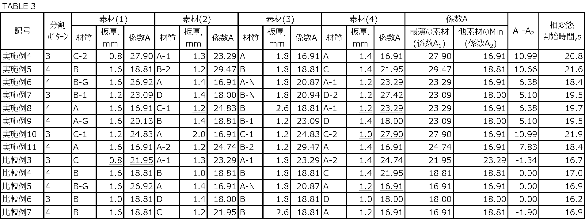
表3を参照して、実施例4~11では、素材(1)~(4)のうち最小の板厚tminの素材の係数A1が比較的厚肉の他の素材の中で最小の係数A2よりも大きくなっている。これに対して、比較例3~7では、素材(1)~(4)のうち最小の板厚tminの係数A1が比較的厚肉の他の素材の中での最小の係数A2以下となっている。各実施例及び各比較例において最小の板厚tminを有する素材が複数枚存在する場合、最小の板厚tminを有する素材の係数Aの中で最小の値を係数A1として、他の素材の係数A2と比較することとした。
各実施例を対応する比較例と比較すると、相変態開始時間が延長されていることがわかる。例えば、最薄の素材(4)の材質以外は同一の条件である実施例6及び比較例5を比較すると、実施例6では、比較例5に対して相変態開始時間が遅くなっている。実施例6では、最薄の素材(4)の係数A1が他の素材(1)~(3)の中で最小の係数A2よりも大きく、最薄の素材の焼入れ性が他の1つ以上の素材の焼入れ性と比べて高くなっている。一方、比較例5では、最薄の素材(4)の係数A1が他の素材(1)~(3)の中で最小の係数A2以下であり、最薄の素材の焼入れ性が他の素材の焼入れ性と同等以下となっている。実施例6では、最薄の素材の焼入れ性を他の素材の焼入れ性よりも高くしたことにより、比較例5と比べて最薄の素材の相変態開始時間が延長され、最薄の素材の相変態開始時間と比較的厚肉の他の素材の相変態開始時間とが均一化された。したがって、実施例6では、ブランクの加熱を完了した後、最薄の素材においてフェライトへの相変態が開始する前に成形を開始しやすくなり、構造部材に均一に焼きが入りやすくなった。
図8E~図8Gに示す分割パターン5~7について、解析の条件及び結果を表4に示す。図8E~図8Gにおいて、構造部材は5枚の素材(1)~(5)によって形成されている。

表4を参照して、実施例12~17では、素材(1)~(5)のうち最小の板厚tminの素材の係数A1が比較的厚肉の他の素材の中で最小の係数A2よりも大きくなっている。これに対して、比較例8~11では、素材(1)~(5)のうち最小の板厚tminの素材の係数A1が比較的厚肉の他の素材の中で最小の係数A2以下となっている。各実施例及び各比較例において最小の板厚tminを有する素材が複数枚存在する場合は、最小の板厚tminを有する素材の係数Aの中で最小の値を係数A1として、他の素材の係数A2と比較することとした。
各実施例を対応する比較例と比較すると、相変態開始時間が延長されていることがわかる。例えば、最薄の素材(1)及び(4)の材質以外は同一の条件である実施例12及び比較例8を比較すると、実施例12では、比較例8に対して相変態開始時間が遅くなっている。実施例12では、最薄の素材(1)及び(4)の係数A1が他の素材(2)、(3)、及び(5)の中で最小の係数A2よりも大きく、最薄の素材の焼入れ性が他の1つ以上の素材の焼入れ性と比べて高くなっている。実施例12では、最薄の素材(1)及び(4)の係数A1は、他の素材(2)、(3)、及び(5)の全ての係数Aよりも大きくなっている。一方、比較例8では、最薄の素材(1)及び(4)の係数A1が他の素材(2)、(3)、及び(5)の中で最小の係数A2以下であり、最薄の素材の焼入れ性が他の素材の焼入れ性と同等以下となっている。実施例12では、最薄の素材の焼入れ性を他の素材の焼入れ性よりも高くしたことにより、比較例8と比べて最薄の素材の相変態開始時間が延長され、最薄の素材の相変態開始時間と比較的厚肉の他の素材の相変態開始時間とが均一化された。したがって、実施例12では、ブランクの加熱を完了した後、最薄の素材においてフェライトへの相変態が開始する前に成形を開始しやすくなり、構造部材に均一に焼きが入りやすくなった。
また、例えば、最薄の素材(1)、(3)、及び(5)の材質以外は同一の条件である実施例13及び比較例9を比較すると、実施例13では、比較例9に対して相変態開始時間が遅くなっている。実施例13では、最薄の素材(1)、(3)、及び(5)の中で最小の係数A1が他の素材(2)及び(4)の中で最小の係数A2よりも大きく、最薄の素材の焼入れ性が他の1つ以上の素材の焼入れ性と比べて高くなっている。実施例13では、最薄の素材(1)、(3)、及び(5)の全ての係数Aが他の素材(2)及び(4)の係数Aよりも大きくなっている。一方、比較例9では、最薄の素材(1)、(3)、及び(5)の中で最小の係数A1が他の素材(2)及び(4)の中で最小の係数A2以下であり、最薄の素材の焼入れ性が他の素材の焼入れ性と同等以下となっている。実施例13では、最薄の素材の焼入れ性を他の素材の焼入れ性よりも高くしたことにより、比較例9と比べて最薄の素材の相変態開始時間が延長され、最薄の素材の相変態開始時間と比較的厚肉の他の素材の相変態開始時間とが均一化された。したがって、実施例13では、ブランクの加熱を完了した後、最薄の素材においてフェライトへの相変態が開始する前に成形を開始しやすくなり、構造部材に均一に焼きが入りやすくなった。
表2~表4に示す各実施例及び各比較例では、素材同士が突合せ後のレーザー接合(突合せ接合)によって接合されている。一方、以下の表5に示す各実施例及び各比較例では、一部の素材が例えばスポット溶接により接合されており、オーバーラップ部を形成する。

表5及び図8Fを参照して、実施例18及び比較例12では、素材(2)と素材(5)、素材(3)と素材(4)、及び素材(4)と素材(5)がそれぞれその接合部においてオーバーラップ部を形成する。表5及び図8Eを参照して、実施例19及び比較例13では、素材(2)と素材(5)、及び素材(3)と素材(4)がそれぞれその接合部においてオーバーラップ部を形成する。
表5に示すように、実施例18及び19では、素材(1)~(5)のうち最小の板厚tminの素材の係数A1が比較的厚肉の他の素材の中で最小の係数A2よりも大きくなっている。これに対して、比較例12及び13では、素材(1)~(5)のうち最小の板厚tminの係数A1が比較的厚肉の他の素材の中で最小の係数A2以下となっている。
表5より、実施例18及び19では、比較例12及び13と比べて相変態開始時間が遅くなっている。したがって、ブランクにオーバーラップ部が存在する場合であっても、最薄の素材の係数A1を他の素材の中で最小の係数A2よりも大きくすることにより、ブランクにおける各素材の相変態開始時間を均一化できることが確認された。
[第2実施例]
ダブルドアリング部品である構造部材のプレス成形(ホットスタンプ)について、構造部材に含まれる素材の材質及び板厚、並びに構造部材の分割パターンを変更しながら、第1実施例と同様の解析を実施した。
ダブルドアリング部品である構造部材のプレス成形(ホットスタンプ)について、構造部材に含まれる素材の材質及び板厚、並びに構造部材の分割パターンを変更しながら、第1実施例と同様の解析を実施した。
素材である鋼板は、第1実施例と同様、表1に示すものの中から選択した。構造部材の分割パターンは、図9A~図9Dに示す通りである。図9A~図9Dでは、ダブルドアリング部品である構造部材に含まれる鋼板(素材)の枚数と、構造部材における鋼板同士の接合部の位置を示している。図9A~図9Dにおいて、素材である各鋼板には括弧書きで数字を付与している。
図9A及び図9Bに示す分割パターン8及び9について、解析の条件及び結果を表6に示す。図9A及び図9Bにおいて、構造部材は6枚の素材(1)~(6)によって形成されている。

表6を参照して、実施例20及び21では、素材(1)~(6)のうち最小の板厚tminの係数A1が比較的厚肉の他の素材の中で最小の係数A2よりも大きくなっている。これに対して、比較例14及び15では、素材(1)~(6)のうち最小の板厚tminの係数A1が比較的厚肉の他の素材の中で最小の係数A2以下となっている。
表6より、A1-A2>0とした実施例20及び21では、A1-A2≦0である比較例14及び15と比べて相変態開始時間が延長されていることがわかる。したがって、最薄の素材の焼入れ性を他の1つ以上の素材の焼入れ性と比較して高くすることにより、最薄の素材においてフェライトへの相変態が開始する前にブランクの成形が開始されやすくなり、構造部材に均一に焼きを入れることが可能となるといえる。
図9C及び図9Dに示す分割パターン10及び11について、解析の条件及び結果を表7に示す。図9C及び図9Dにおいて、構造部材は7枚の素材(1)~(7)によって形成されている。

表7を参照して、実施例22~24では、素材(1)~(7)のうち最小の板厚tminを有する素材の中で最小の係数A1が比較的厚肉の他の素材の中で最小の係数A2よりも大きくなっている。これに対して、比較例16及び17では、素材(1)~(7)のうち最小の板厚tminを有する素材の中で最小の係数A1が比較的厚肉の他の素材の中で最小の係数A2以下となっている。
表7より、A1-A2>0とした実施例22~24では、A1-A2≦0である比較例16及び17と比べて相変態開始時間が延長されていることがわかる。したがって、最薄の素材の焼入れ性を他の1つ以上の素材の焼入れ性と比較して高くすることにより、最薄の素材においてフェライトへの相変態が開始する前にブランクの成形が開始されやすくなり、構造部材に均一に焼きを入れることが可能となるといえる。
[第3実施例]
ブランクをその全体が910℃に到達するまでの時間、加熱炉温920℃で加熱したのち、17秒でプレス装置に搬送し、成形速度40mm/sにてホットスタンプ成形を行い、3000kNで加圧しながら20秒間下死点で保持し、ホットスタンプ構造部材を取得した。これらの構造部材の最薄部より、上記実施形態において説明した方法で分析サンプルを採取し、マルテンサイト分率のばらつきを測定した。また別途、これらの構造部材について形状精度測定及び衝撃吸収性能測定を実施した。各評価結果を表8に示す。
ブランクをその全体が910℃に到達するまでの時間、加熱炉温920℃で加熱したのち、17秒でプレス装置に搬送し、成形速度40mm/sにてホットスタンプ成形を行い、3000kNで加圧しながら20秒間下死点で保持し、ホットスタンプ構造部材を取得した。これらの構造部材の最薄部より、上記実施形態において説明した方法で分析サンプルを採取し、マルテンサイト分率のばらつきを測定した。また別途、これらの構造部材について形状精度測定及び衝撃吸収性能測定を実施した。各評価結果を表8に示す。
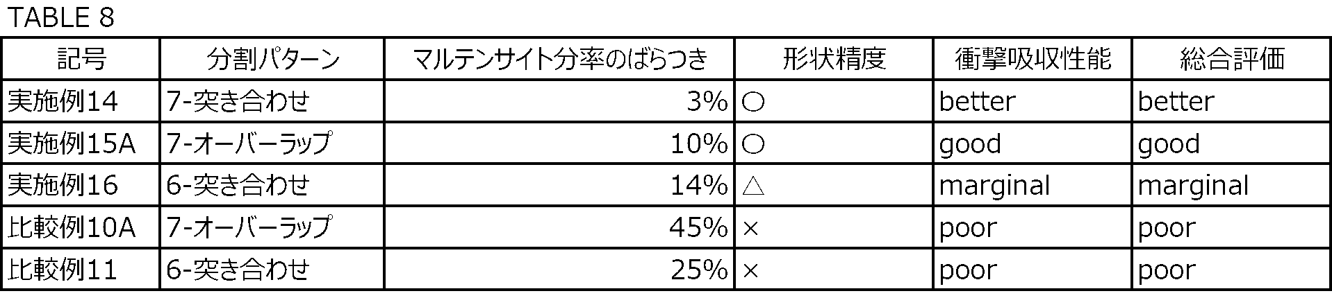
表8中の実施例14及び16は、表4に示す実施例14及び16と同一条件の実施例である。実施例15Aは、分割パターン及び素材の組み合わせが表4に示す実施例15と同一であるが、一部の素材が接合部においてオーバーラップ部を形成している。比較例10Aは、分割パターン及び素材の組み合わせが表4に示す比較例10と同一であるが、一部の素材が接合部においてオーバーラップ部を形成している。実施例15A及び比較例10Aでは、素材(1)と素材(2)、素材(1)と素材(3)、素材(2)と素材(5)、素材(4)と素材(5)がそれぞれその接合部においてオーバーラップ部を形成する。比較例11は、表4に示す比較例11と同一条件の比較例である。
表8において、マルテンサイト分率のばらつきとは、上記実施形態で説明した通り、最小の板厚tminを有する素材の位置での構造部材の断面において、最大のマルテンサイト分率(%)から最小のマルテンサイト分率(%)を減じた値である。
形状精度については、断面視で略ハット状の構造部材を他の部材に取り付けたとき、構造部材と相手部材との重ね合わせ部において構造部材が相手部材に対してどの程度離れているかで評価した。表8では、相手部材の表面からの距離が±2.0mm以内であった場合を○、±2.0mm超且つ±3.0mm以内であった場合を△、±3.0mm超であった場合を×で表示している。
衝撃吸収性能については、表8に示す実施例及び比較例のそれぞれの構造部材(ドアリングアウタ部品)に対してドアリングインナ部品をスポット溶接で接合することでドアリングの組立部品を作製し、これを部分構造評価用試験体とした。そして、各試験体の周囲を車体衝突時の変形を再現するための拘束治具で固定し、ドアリングアウタ部品側(車体の側面側)からバリアを衝突させて、このときの最大侵入量を衝撃吸収性能として評価した。衝撃吸収性能は、各素材をそれぞれホットスタンプによって成形した後に接合してドアリングアウタ部品としたものの衝撃吸収性能をベースとし、ベースの衝撃吸収性能に対する比較で評価した。表8において、ベースの衝撃吸収性能と同等の衝撃吸収性能をgood、ベースの衝撃吸収性能よりも優れた衝撃吸収性能をbetter、ベースの衝撃吸収性能よりも若干低い衝撃吸収性能をmarginal、さらに低い衝撃吸収性能をpoorで表示している。形状精度及び衝撃吸収性能の総合評価についても、poor、marginal、good、及びbetterの四段階で示している。
表8に示す各実施例がA1-A2>0を満たすのに対し、各比較例ではA1-A2≦0となっている。比較例10A及び11ではマルテンサイト分率のばらつきが20%を超えたのに対し、実施例14、15A、及び16では、マルテンサイト分率のばらつきが20%以下となった。実施例14、15A、及び16では、マルテンサイト分率のばらつきが15%以下まで低減されていた。実施例14、15A、及び16では、比較例10A及び11と比較して形状精度も良好となった。
マルテンサイト分率のばらつきが小さい実施例14、15A、及び16では、比較例10A及び11と比較して衝撃吸収性能も向上した。特に、マルテンサイト分率のばらつきが10%以下の実施例14及び15Aではベース以上の衝撃吸収性能を確保することができた。すなわち、ブランクの段階で複数の素材を一体化して環状の構造部材を成形しているにもかかわらず、素材を個々にプレス成形した後に接合した構造部材と同等以上の衝撃吸収性能を確保することができた。
10:構造部材
11:部材本体
20,20A,20B:ブランク
21:鋼板(第1鋼板)
22:鋼板(第2鋼板)
23:鋼板
40:金型
111:フロントピラー
112:センターピラー
113:ロッカー
11:部材本体
20,20A,20B:ブランク
21:鋼板(第1鋼板)
22:鋼板(第2鋼板)
23:鋼板
40:金型
111:フロントピラー
112:センターピラー
113:ロッカー
Claims (5)
- ホットスタンプ用のブランクであって、
当該ブランクの平面視で環状を有するように配置され、接合された複数の鋼板を備え、
前記複数の鋼板は、
当該複数の鋼板において最小の板厚を有する第1鋼板と、
前記第1鋼板の板厚よりも大きい板厚を有する第2鋼板と、
を含み、
前記第1鋼板の化学組成を用いて以下の式(1)で算出される係数Aの値は、前記第2鋼板の化学組成を用いて以下の式(1)で算出される係数Aの値よりも大きい、ブランク。
A=1.48×(2.7×C+0.4×Si+Mn+0.45×Ni+0.8×Cr+2×Mo)3.42 (1)
ただし、上記式(1)中の元素記号には、対応する元素の含有量(質量%)が代入される。 - 請求項1に記載のブランクであって、
前記第1鋼板の板厚をtmin、前記複数の鋼板の板厚の中で最大の板厚をtmaxとしたとき、tmax-tmin≧0.2(mm)である、ブランク。 - 構造部材の製造方法であって、
請求項1又は2に記載のブランクを準備する工程と、
前記ブランクに含まれる前記複数の鋼板をオーステナイト変態完了温度以上に加熱する工程と、
金型を用い、加熱された前記ブランクを平面視で環状の構造部材に成形するとともに焼入れする工程と、
を備える、製造方法。 - 構造部材であって、
最小の板厚を有する第1鋼板と、前記第1鋼板の板厚よりも大きい板厚を有する第2鋼板とを含み、互いに接合された複数の鋼板によって形成され、平面視で環状を有する部材本体を備え、
前記第1鋼板の化学組成を用いて以下の式(1)で算出される係数Aの値は、前記第2鋼板の化学組成を用いて以下の式(1)で算出される係数Aの値よりも大きい、構造部材。
A=1.48×(2.7×C+0.4×Si+Mn+0.45×Ni+0.8×Cr+2×Mo)3.42 (1)
ただし、上記式(1)中の元素記号には、対応する元素の含有量(質量%)が代入される。 - 請求項4に記載の構造部材であって、
前記構造部材は、自動車のドアリング部品であり、
前記部材本体は、フロントピラーと、センターピラーと、前記フロントピラーと前記センターピラーとを接続するロッカーとを含む、構造部材。
Priority Applications (1)
| Application Number | Priority Date | Filing Date | Title |
|---|---|---|---|
| JP2024576646A JP7684626B2 (ja) | 2023-06-06 | 2024-06-04 | ブランク、構造部材の製造方法、及び構造部材 |
Applications Claiming Priority (2)
| Application Number | Priority Date | Filing Date | Title |
|---|---|---|---|
| JP2023093559 | 2023-06-06 | ||
| JP2023-093559 | 2023-06-06 |
Publications (1)
| Publication Number | Publication Date |
|---|---|
| WO2024253077A1 true WO2024253077A1 (ja) | 2024-12-12 |
Family
ID=93796001
Family Applications (1)
| Application Number | Title | Priority Date | Filing Date |
|---|---|---|---|
| PCT/JP2024/020325 Ceased WO2024253077A1 (ja) | 2023-06-06 | 2024-06-04 | ブランク、構造部材の製造方法、及び構造部材 |
Country Status (2)
| Country | Link |
|---|---|
| JP (1) | JP7684626B2 (ja) |
| WO (1) | WO2024253077A1 (ja) |
Families Citing this family (1)
| Publication number | Priority date | Publication date | Assignee | Title |
|---|---|---|---|---|
| WO2022064256A1 (en) * | 2020-09-25 | 2022-03-31 | Arcelormittal | Side structure for a motor vehicle |
Citations (6)
| Publication number | Priority date | Publication date | Assignee | Title |
|---|---|---|---|---|
| JP2004058082A (ja) * | 2002-07-26 | 2004-02-26 | Aisin Takaoka Ltd | テーラードブランクプレス成形品の製造方法 |
| JP2013501631A (ja) * | 2010-11-03 | 2013-01-17 | ヒュンダイ ハイスコ | 熱処理硬化鋼板を用いた局部的に異種強度を有する自動車部品の製造方法 |
| WO2013147035A1 (ja) * | 2012-03-28 | 2013-10-03 | 新日鐵住金株式会社 | ホットスタンプ用テーラードブランクおよびホットスタンプ部材ならびにそれらの製造方法 |
| JP2019014935A (ja) * | 2017-07-06 | 2019-01-31 | 新日鐵住金株式会社 | 熱間プレス用鋼板とその製造方法、ならびに熱間プレス成形部材およびその製造方法 |
| JP2021528248A (ja) * | 2018-06-25 | 2021-10-21 | オートテック・エンジニアリング・ソシエダッド・リミターダAutotech Engineering, S.L. | 車両のボディサイド構造フレーム |
| CN217893040U (zh) * | 2022-08-12 | 2022-11-25 | 浙江吉利控股集团有限公司 | 侧围加强板、侧围加强板总成和车辆 |
-
2024
- 2024-06-04 JP JP2024576646A patent/JP7684626B2/ja active Active
- 2024-06-04 WO PCT/JP2024/020325 patent/WO2024253077A1/ja not_active Ceased
Patent Citations (6)
| Publication number | Priority date | Publication date | Assignee | Title |
|---|---|---|---|---|
| JP2004058082A (ja) * | 2002-07-26 | 2004-02-26 | Aisin Takaoka Ltd | テーラードブランクプレス成形品の製造方法 |
| JP2013501631A (ja) * | 2010-11-03 | 2013-01-17 | ヒュンダイ ハイスコ | 熱処理硬化鋼板を用いた局部的に異種強度を有する自動車部品の製造方法 |
| WO2013147035A1 (ja) * | 2012-03-28 | 2013-10-03 | 新日鐵住金株式会社 | ホットスタンプ用テーラードブランクおよびホットスタンプ部材ならびにそれらの製造方法 |
| JP2019014935A (ja) * | 2017-07-06 | 2019-01-31 | 新日鐵住金株式会社 | 熱間プレス用鋼板とその製造方法、ならびに熱間プレス成形部材およびその製造方法 |
| JP2021528248A (ja) * | 2018-06-25 | 2021-10-21 | オートテック・エンジニアリング・ソシエダッド・リミターダAutotech Engineering, S.L. | 車両のボディサイド構造フレーム |
| CN217893040U (zh) * | 2022-08-12 | 2022-11-25 | 浙江吉利控股集团有限公司 | 侧围加强板、侧围加强板总成和车辆 |
Also Published As
| Publication number | Publication date |
|---|---|
| JP7684626B2 (ja) | 2025-05-28 |
| JPWO2024253077A1 (ja) | 2024-12-12 |
Similar Documents
| Publication | Publication Date | Title |
|---|---|---|
| JP5509337B2 (ja) | 熱処理硬化鋼板を用いた局部的に異種強度を有する自動車部品の製造方法 | |
| RU2675889C2 (ru) | Способ производства паяного соединения и паяное соединение | |
| JP7211493B2 (ja) | ブランクおよび構造部材 | |
| JPWO2020059804A1 (ja) | テーラードブランク、テーラードブランクの製造方法、プレス成形品、及び、プレス成形品の製造方法 | |
| US20140220381A1 (en) | Clad sheet for motor vehicle body | |
| RU2699427C1 (ru) | Составной компонент, полученный путем механического соединения клинчеванием, и способ его изготовления | |
| JP7684626B2 (ja) | ブランク、構造部材の製造方法、及び構造部材 | |
| CN119840735A (zh) | 用于机动车辆的后底置结构 | |
| JP7656248B2 (ja) | ブランク、構造部材の製造方法、及び構造部材 | |
| KR20180058540A (ko) | 도금 보론강의 용접성 개선방법 및 이에 의해 제조되는 용접성이 개선된 도금 보론강 | |
| JP7684628B1 (ja) | 自動車リアモジュール | |
| KR20200040565A (ko) | 동시성형 핫스탬핑 방법 및 핫스탬핑 제품 | |
| JP7678401B1 (ja) | ブランク、構造部材の製造方法、及び構造部材 | |
| JP7741455B2 (ja) | ブランク、構造部材の製造方法、及び構造部材 | |
| KR20220104211A (ko) | 사전-코팅된 강판으로 제조된 용접된 강 부품의 용접 금속 구역의 기계적 강도를 증가시키기 위한 추가 코팅을 포함하는 사전-코팅된 강판 | |
| JP4789253B2 (ja) | 成形性に優れたアルミニウム合金接合材およびその製造方法 | |
| JP7769278B1 (ja) | ブランク、構造部材の製造方法、及び構造部材 | |
| US20200230917A1 (en) | Hot-forming composite material, production therof, component, and use thereof | |
| JP2025146839A (ja) | ブランク、構造部材の製造方法、及び構造部材 | |
| WO2025134965A1 (ja) | 構造部材 | |
| JP2023059596A (ja) | 熱間プレス成形品、テーラードブランク、熱間プレス成形品の製造方法、及びテーラードブランクの製造方法 | |
| CA3289833A1 (en) | Blank, production method for structural member and structural member | |
| JP4513587B2 (ja) | 焼入変形低減効果に優れた複合部品の製造方法 | |
| EP4703060A1 (en) | Blank, method for manufacturing structural member, and structural member | |
| JP7810935B2 (ja) | ブランク、構造部材の製造方法、及び構造部材 |
Legal Events
| Date | Code | Title | Description |
|---|---|---|---|
| WWE | Wipo information: entry into national phase |
Ref document number: 2024576646 Country of ref document: JP |
|
| 121 | Ep: the epo has been informed by wipo that ep was designated in this application |
Ref document number: 24819307 Country of ref document: EP Kind code of ref document: A1 |
|
| NENP | Non-entry into the national phase |
Ref country code: DE |
|
| 122 | Ep: pct application non-entry in european phase |
Ref document number: 24819307 Country of ref document: EP Kind code of ref document: A1 |