WO2024253052A1 - 手首関節ユニットおよびそれを備えた作業装置 - Google Patents
手首関節ユニットおよびそれを備えた作業装置 Download PDFInfo
- Publication number
- WO2024253052A1 WO2024253052A1 PCT/JP2024/020155 JP2024020155W WO2024253052A1 WO 2024253052 A1 WO2024253052 A1 WO 2024253052A1 JP 2024020155 W JP2024020155 W JP 2024020155W WO 2024253052 A1 WO2024253052 A1 WO 2024253052A1
- Authority
- WO
- WIPO (PCT)
- Prior art keywords
- bevel gear
- rotating member
- arm
- wrist joint
- joint unit
- Prior art date
- Legal status (The legal status is an assumption and is not a legal conclusion. Google has not performed a legal analysis and makes no representation as to the accuracy of the status listed.)
- Ceased
Links
Images




Classifications
-
- B—PERFORMING OPERATIONS; TRANSPORTING
- B25—HAND TOOLS; PORTABLE POWER-DRIVEN TOOLS; MANIPULATORS
- B25J—MANIPULATORS; CHAMBERS PROVIDED WITH MANIPULATION DEVICES
- B25J17/00—Joints
- B25J17/02—Wrist joints
Definitions
- the present invention relates to a wrist joint unit and a work device equipped with the same, and relates to technology that can be applied to, for example, SCARA robots, Cartesian robots, and vertical articulated robots.
- a wrist joint unit is rotatably connected to the tip of the robot arm.
- This wrist joint unit has two mutually perpendicular rotation axes, and includes a first member that rotates around one axis, and a second member connected to the first member so as to rotate around the other axis.
- An end effector is installed on the second member so as to perform a predetermined task. Since the wrist joint unit is provided at the tip of the robot's arm, it is preferable that it is lightweight, and since the specified tasks are performed by the end effector attached to the wrist joint unit, it is preferable that it is small in size to avoid interference with the surroundings.
- Patent Document 1 discloses a wrist unit. This wrist unit has two drive motors, and a multi-stage pulley and belt mechanism is installed between these drive motors and a wrist that is arranged so that it can oscillate and rotate by these drive motors. By ensuring the necessary reduction ratio without using a reducer such as a wave gear reducer, it is possible to avoid an increase in size and high costs.
- Patent document 2 discloses a vertical articulated robot.
- a B arm is rotatably supported on an A arm in a cantilevered manner.
- a through hole is provided in the reduction gear that drives the A arm, and the transmission mechanism that drives the B arm is inserted through the through hole, which allows for a reduction in size and weight.
- the central axis of oscillation is supported at both ends, which increases the width of the wrist and raises the risk of the wrist interfering with the surroundings when performing a specific task.
- the rotation range is limited due to the structure.
- the arm at the tip is supported by a cantilever, which allows for a certain degree of miniaturization, but since a reduction gear and other components are mounted on the rotating part, there is a limit to how much the robot can be made smaller and lighter.
- the object of the present invention is to provide a wrist joint unit that can be made smaller and lighter, and a work device equipped with the same.
- the wrist joint unit of the present invention comprises an arm and a first rotating member supported by the arm in a cantilever manner and rotatable about a first rotation axis; a bevel gear that is a second rotating member that is cantilevered on the first rotating member and rotatably provided around a second rotation axis that is perpendicular to the first rotation axis; a first motor supported by the arm and configured to rotate the first rotating member; a second motor supported by the arm and configured to rotate the bevel gear; An end effector is attachable to the bevel gear.
- the first rotating member is supported by the arm at one end, and the bevel gear, which is the second rotating member, is supported by the first rotating member at one end, so that the first and second rotating members can increase the degree of freedom of rotational movement without interfering with the first and second motors and supporting members, etc.
- the first and second rotating members are supported by one end, it is possible to achieve a smaller size and lighter weight than a structure in which the first and second rotating members are supported at both ends.
- the first and second motors are supported by the base arm, not by rotating members that perform rotational movement, so the motor body does not move. This allows for lightweight and compact first and second rotating members to be realized.
- an end effector can be attached to the bevel gear, which is the second rotating member, a wrist joint unit that has a small number of parts and is compact and lightweight can be realized.
- the first rotating member may be rotatably supported relative to the arm via a bearing (1), and the bearing (1) and a bearing (4) that rotatably supports the gear shaft relative to the arm may be provided coaxially. Numbers in parentheses correspond to reference symbols of the embodiments.
- the boss outer diameter D of the bevel gear which is the second rotating member, may have a tolerance range class of h7 or less or g6 or less in the dimensional tolerance used in commonly used fitting shafts, and the boss outer diameter D may have a concentricity of 0.03 mm or less with respect to the boss inner diameter d of the bevel gear into which the bearing (3) is fitted.
- the accuracy of the operation of the end effector attached to the bevel gear can be improved compared to a structure in which the boss outer diameter D of the bevel gear exceeds h7, or a structure in which the concentricity of the boss outer diameter D of the bevel gear with respect to the boss inner diameter d of the bevel gear exceeds 0.03 mm.
- the boss end face of the bevel gear which is the second rotating member, may have a perpendicularity of 0.05 mm or less with respect to the boss inner diameter d of the bevel gear into which the bearing (3) is fitted. In this case, it becomes possible to accurately and appropriately attach the end effector to the bevel gear.
- the boss side and end face of the bevel gear which is the second rotating member, may be provided with a screw hole for mounting the end effector.
- the end effector can be easily attached and detached from the bevel gear.
- the boss end face of the bevel gear which is the second rotating member, may be provided with an attachment hole in which a pin can be installed to ensure reproducibility of the attachment of the end effector and to prevent misalignment in the rotational direction.
- a pin in the attachment hole in the boss end face of the bevel gear, it is possible to ensure reproducibility of the attachment of the end effector and to prevent misalignment in the rotational direction, and the end effector can be easily attached and detached from the bevel gear.
- the boss outer diameter D of the bevel gear which is the second rotating member, may be provided with a shoulder that regulates the mounting position of the end effector in the second rotation axis direction, and the corner of the shoulder may have a radius R of 0.2 mm or less, or the corner of the shoulder may be provided with a recess.
- the end effector when the end effector is fitted onto the boss outer diameter of the bevel gear, the end effector reliably abuts against the shoulder, ensuring the repeatability of the mounting position of the end effector in the second rotation axis direction.
- the working device of the present invention is equipped with any one of the wrist joint units. This working device allows work to be done in narrower spaces, near walls, or with multiple devices lined up with small intervals between them, compared to working devices using conventional wrist joint units.
- FIG. 1 is a longitudinal sectional view of a wrist joint unit according to a first embodiment of the present invention.
- FIG. 13 is a diagram showing a schematic relationship between the two motors of the wrist joint unit and the spur gears.
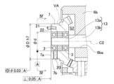
- FIG. 4 is an enlarged partial cross-sectional view showing the vicinity of a second rotating member of the wrist joint unit.
- FIG. 4 is a view taken along line IV-IV in FIG. 3 .
- FIG. 4 is a partial enlarged view of the VA portion of FIG. 3 .
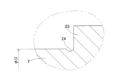
- FIG. 5B is a partially enlarged view showing a modified example in which the shoulder corner of FIG. 5A is partially modified.
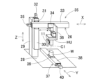
- FIG. 1 is a diagram showing an example 1 of a working device equipped with a wrist joint unit according to any one of the embodiments.
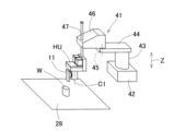
- FIG. 11 is a diagram showing a second example of a working device equipped with a wrist joint unit according to any one of the embodiments.
- a wrist joint unit according to an embodiment of the present invention will be described with reference to Figures 1 to 5A.
- a working device including the wrist joint unit, which will be described later, is used in, for example, medical equipment or industrial equipment.
- the wrist joint unit HU includes an arm 5, a first rotating member 6 supported by the arm 5 in a cantilever manner and rotatable about a first rotation axis C1, a reduction gear mechanism 8 including a second rotating member 7 supported by the first rotating member 6 in a cantilever manner and rotatable about a second rotation axis C2 perpendicular to the first rotation axis C1, and first and second motors 9 and 10 serving as drive sources.
- An end effector 11 is attached to the bevel gear 7 serving as the second rotating member.
- the working device performs work by positioning the end effector 11 attached to the bevel gear 7 with respect to a workpiece.
- the arm 5 serving as the base has a base arm 5b and a tip arm 5a connected to the base arm 5b.
- the tip arm 5a is formed in a cylindrical shape with a bottom, and the base arm 5b is connected to the peripheral edge of the opening of the cylindrical portion of the tip arm 5a.
- a part of the reduction mechanism 8 described later is provided in a space S1 surrounded by the base arm 5b and the tip arm 5a.
- the first rotating member 6 is supported by the distal arm 5a in a cantilever manner and is provided rotatably around the first rotation axis C1 by the bearing 1.
- the first rotating member 6 has a hollow cylindrical base end rotating table 6a and a tip end rotating table 6b fixed to the base end rotating table 6a.
- the base end rotating table 6a and the tip end rotating table 6b are provided as separate members and connected to each other, but the base end rotating table 6a and the tip end rotating table 6b may be provided integrally.
- the term "provided integrally” means that the base end rotating table 6a and the tip end rotating table 6b are not formed by combining a plurality of elements but are formed as a part or the whole of a single object from a single material by, for example, machining.
- the first and second rotating axes C1 and C2 mean rotation axes that do not have a substance.
- the outer peripheral surface of the outer ring of the bearing 1 is fitted and fixed to the bottom of the tip arm 5a, which is a bottomed cylinder, and the outer peripheral surface of the base rotating table 6a is fitted and fixed to the inner peripheral surface of the inner ring of the bearing 1.
- a tip rotating table 6b which is, for example, a square cylinder, is connected to one side of the base rotating table 6a and is provided so as to protrude in one direction of the first rotation axis, i.e., the upper side in FIG. 1.
- a space S2 is formed in the tip rotating table 6b to prevent interference with the bevel gears 7 and 12, and a hole 6ba is formed in which the gear shaft 13 that supports the rotation of the bevel gear 7 is fitted and fixed.
- a cover 14 is provided on one side of the tip rotating table 6b to prevent foreign matter from entering the space S2 and to prevent grease from leaking.
- the first and second motors 9 and 10 are supported by the base-side arm 5b of the arm 5.
- the first motor 9 is a drive source that rotates the first rotating member 5
- the second motor 10 is a drive source that rotates the bevel gear 7, which is the second rotating member.
- a hole 5ba that supports the motor body of the first motor 9 is formed in the base-side arm 5b, and the motor shaft is housed in the space S1 in the arm 5.
- the rotation axis of the motor shaft is arranged parallel to the first rotation axis C1.
- a hole that supports the motor body of the second motor 10 (Fig. 2) is also formed in the base-side arm 5b, and the motor shaft of the second motor 10 (Fig. 2) is also housed in the space S1 in the arm 5.
- the rotation axis of the motor shaft is also arranged parallel to the first rotation axis C1.
- the reduction mechanism 8 includes a first reduction mechanism 8A that reduces the rotation of the first motor 9, and a second reduction mechanism 8B that reduces the rotation of the second motor 10 (FIG. 2).
- the first reduction mechanism 8A has a spur gear 15 fixed to the motor shaft of the first motor 9, a spur gear 16 fixed to the other side of the base end side rotating table 6a and meshing with the spur gear 15, and a bearing 1 that supports the first rotating member 6 relative to the arm 5.
- the spur gear 16 is rotatable around the first rotating axis C1, and the spur gears 15 and 16 are housed in the space S1 in the arm 5.
- a deep groove ball bearing capable of receiving radial and axial loads is applied as the bearing 1.
- the second reduction mechanism 8B has spur gears 17, 18 (Fig. 2), bearings 2, 4, a base-side gear shaft 19, bevel gears 12, 7, bearing 3, and a tip-side gear shaft 13.
- the spur gear 17 (Fig. 2) is fixed to the motor shaft of the second motor 10 (Fig. 2).
- the base-side gear shaft 19 is rotatably supported by the base-side arm 5b and the base-side rotating table 6a via bearings 4, 2.
- the bearings 2, 4 are provided coaxially with the bearing 1.
- a spur gear 18 is fixed to the base end of the base-side gear shaft 19, and a bevel gear 12 is fixed to the tip of the gear shaft 19.
- the spur gear 18 is housed in the space S1 in the arm 5, and the bevel gear 12 is housed in the space S2 of the tip-side rotating table 6b, and meshes with the bevel gear 7, which is the second rotating member.
- the gear shaft 13 on the tip side extends in the direction of the second rotation axis C2.
- the gear shaft 13 on the tip side has a small diameter portion 13a located at the longitudinal tip and a large diameter portion 13b coaxially connected to the small diameter portion 13a.
- Most of the large diameter portion 13b is fitted and fixed into a hole 6ba in the tip side rotating table 6b, and the small diameter portion 13a is arranged to protrude from the hole 6ba.
- a bevel gear 7 is fixed to the small diameter portion 13a of the gear shaft 13 via multiple (two in this example) bearings 3, 3.
- each bearing 3 is fitted and fixed to the small diameter portion 13a of the gear shaft 13, and the boss inner diameter d of the bevel gear 7 is fitted and fixed to the outer ring of each bearing 3.
- deep groove ball bearings capable of receiving radial and axial loads are also used for bearings 2, 3, and 4 in FIG. 1.
- the bevel gear 7 shown in FIG. 1 is driven and rotated around the second rotation axis C2 at a predetermined reduction ratio by the second reduction mechanism 8B.
- the base end rotating table 6a is rotatably supported by the tip end arm 5a via bearing 1, and the base end gear shaft 19 is fixed to this base end rotating table 6a via bearing 2, and the bearings 1 and 2 are arranged coaxially, so that when the first motor 9 is driven to rotate, the base end gear shaft 19 rotates with it.
- the bevel gear 7 rotates around the second rotation axis C2.
- the bevel gear 7, which is the second rotating member, has a boss outer diameter D of the bevel gear 7 that is equal to or smaller than h7 or equal to or smaller than g6 in the dimensional tolerances used for commonly used fitting shafts so that the end effector 11 (Fig. 1) can be properly attached.
- the dimensional tolerance of the boss outer diameter D is in the tolerance range class of a shrink fit such as h7, h6, h5, g6, etc.
- the coaxiality of the boss outer diameter D with the boss inner diameter d of the bevel gear 7 that fits the bearing 3 is equal to or smaller than 0.03 mm.
- the tolerance range classes "h7, h6, h5, g6" are specified in the Japanese Industrial Standards JIS B 0401-01, 02.
- the accuracy of operation of the end effector attached to the bevel gear 7 can be improved for a structure in which the boss outer diameter D of the bevel gear 7 exceeds h7, or a structure in which the concentricity of the boss outer diameter D relative to the boss inner diameter d of the bevel gear 7 exceeds 0.03 mm.
- the boss end face 7a of the bevel gear 7 has a perpendicularity of 0.05 mm or less with respect to the boss inner diameter d of the bevel gear 7 into which the bearing 3 is fitted. This makes it possible to appropriately attach the end effector to the bevel gear 7 with high precision.
- the boss side surface 7b and end surface 7a of the bevel gear 7 are provided with screw holes 20 for attaching an end effector.
- a plurality of screw holes 20 are provided at equal intervals on the boss end surface 7a, and each screw hole 20 is formed to extend parallel to the second rotation axis direction.
- the screw holes 20 provided on the boss side surface 7b are formed to extend in a radial direction perpendicular to the second rotation axis direction. In this case, the end effector can be easily attached and detached to the bevel gear 7.
- the boss end surface 7a of the bevel gear 7, which is the second rotating member, is provided with an attachment hole 22 in which a pin 21 can be installed to ensure reproducibility of the attachment of the end effector and prevent misalignment in the rotational direction.
- the attachment hole 22 extends parallel to the second rotational axis direction.
- a knock pin or the like is used as the pin 21.
- a shoulder 23 is provided on the boss outer diameter D of the bevel gear 7, which is the second rotating member, to regulate the attachment position of the end effector in the second rotation axis direction. Furthermore, the radius R of the corner 23a of the shoulder 23 is 0.2 mm or less, or as shown in Figure 5B, a recess 24 is provided at the corner of the shoulder 23. In this case, when the end effector is fitted into the boss outer diameter D of the bevel gear 7, the end effector reliably abuts against the shoulder 23, ensuring the repeatability of the attachment position of the end effector in the second rotation axis direction.
- the first rotating member 6 is supported by the arm 5 at one end, and the bevel gear 7, which is the second rotating member, is supported by the first rotating member 6 at one end, so that the first and second rotating members 6, 7 can increase the degree of freedom of rotational movement without interfering with the first and second motors 9, 10 (Fig. 2) and supporting members.
- the first and second rotating members 6, 7 are supported by one end, the first and second rotating members 6, 7 can be made smaller and lighter than a structure in which the first and second rotating members 6, 7 are supported by both ends.
- the first and second motors 9, 10 (Fig.
- the wrist joint unit HU further comprises a bevel gear 12 that meshes with the bevel gear 7, and a gear shaft 19 to which the bevel gear 12 is fixed and which is rotatably supported by the arm 5 and the first rotating member 6 via bearings 4 and 2.
- the first rotating member 6 is rotatably supported by the arm 5 via bearing 1, and this bearing 1 and the bearing 4 that rotatably supports the gear shaft 19 by the arm 5 are provided coaxially. Therefore, by rotating both the first and second motors 9 and 10 (Fig. 2) in an appropriate relationship, it is possible to rotate the bevel gear 7, which is the second rotating member, only about the first rotating axis C1. By rotating only the second motor 10 (Fig. 2) without rotating the first motor 9, it is possible to rotate the bevel gear 7, which is the second rotating member, only about the second rotating axis C2.
- At least one of the bearings 1, 2, 3, and 4 may be replaced with a rolling bearing other than a deep groove ball bearing.
- a rolling bearing capable of receiving radial and axial loads is applied.
- an angular ball bearing, a four-point contact ball bearing, a tapered roller bearing, a cross roller bearing, etc. can be used as such a rolling bearing.
- An end effector may be attached to the bevel gear, which is the second rotating member, via an intermediate member such as a tool changer.
- FIG. 6A As shown in Fig. 6A, an orthogonal robot (working device) 25 equipped with a wrist joint unit HU may be used.
- an XZ stage that moves in two orthogonal axial directions, the X-axis and the Z-axis, is applied to the orthogonal robot 25.
- This orthogonal robot 25 includes an X-axis electric actuator 26 and a Z-axis electric actuator 27 that respectively correspond to the X-axis and the Z-axis that are orthogonal to each other.
- the Z-axis electric actuator 27 has a column part 29 that extends in the Z-axis direction, which is the up-down direction in Fig.
- a guide part 30 fixed to one side of the column part 29 a Z-axis stage 31 that slides along the guide part 30, a Z-axis motor 32 that is a drive source of the Z-axis stage 31, and a conversion mechanism such as a ball screw (not shown) that converts the rotation of the Z-axis motor 32 into a linear reciprocating motion along the Z-axis.
- a conversion mechanism such as a ball screw (not shown) that converts the rotation of the Z-axis motor 32 into a linear reciprocating motion along the Z-axis.
- the X-axis electric actuator 26 has a guide section 33 that is supported by the Z-axis stage 31 and extends along the X-axis direction, which is the left-right direction in FIG. 6A, an X-axis stage 34 that slides along the guide section 33, an X-axis motor 35 that is the drive source for the X-axis stage 34, and a conversion mechanism such as a ball screw (not shown) that converts the rotation of the X-axis motor 35 into a linear reciprocating motion along the X-axis.
- a wrist joint unit HU is connected to the X-axis stage 34 via a bracket 36 or the like.
- the first rotation axis C1 of this wrist joint unit HU is arranged, for example, parallel to the Z-axis.
- a Y-axis electric actuator 37 is provided on the support base 28 in the Y-axis direction perpendicular to the X-axis and Z-axis.
- the Y-axis electric actuator 37 has a guide portion 38 extending along the Y-axis direction on the support base 28, a Y-axis stage 39 that slides along the guide portion 38, a Y-axis motor 40 that is the drive source for the Y-axis stage 39, and a conversion mechanism such as a ball screw (not shown) that converts the rotation of the Y-axis motor 40 into a linear reciprocating motion along the Y axis.
- the workpiece W is placed on the Y-axis stage 40.
- the Cartesian robot 25, the Y-axis electric actuator 37 and the motors of the wrist joint unit HU are controlled in cooperation with each other by a control device (not shown).
- the Cartesian robot 25 positions the end effector 11 attached to the tip of the wrist joint unit HU with respect to the workpiece W to perform a desired task.
- This working device makes it possible to work in narrower spaces, close to walls, or by arranging multiple devices with close spacing between them, compared to working devices using conventional wrist joint units.
- a SCARA robot (working device) 41 equipped with a wrist joint unit HU may be used.
- a first arm 44 on the base end side is provided rotatably around the Z-axis direction via a rotation mechanism 43 on a rotation drive source provided on a base unit 42.
- a second arm 46 is provided on the tip of the first arm 44 rotatably around the Z-axis direction via a rotation mechanism 45.
- the wrist joint unit HU is connected to the tip of the second arm 45 via a linear guide mechanism 47 that can be moved and driven in the Z-axis direction.
- the first rotation axis C1 of this wrist joint unit HU is also arranged parallel to the Z-axis.
- the workpiece W is placed and supported on a support table 28.
- the motors of the SCARA robot 41 and wrist joint unit HU are controlled in cooperation with each other by a control device (not shown). This allows the SCARA robot 41 to position the end effector 11 attached to the tip of the wrist joint unit HU with respect to the workpiece W to perform the desired work.
- This work device can also be used in narrower spaces, near walls, or with multiple units lined up at close intervals, compared to work devices using conventional wrist joint units.
- a wrist joint unit may be provided at the tip of a vertical articulated robot with four or fewer axes.
- a wrist joint unit at the tip of a vertical articulated robot with five or six axes. In this case as well, the same effects as described above can be achieved.
- bearings 5 arm 6: first rotating member 7: bevel gear (second rotating member) 9: First motor 10: Second motor 11: End effector 12: Bevel gear 19: Gear shaft 20: Screw hole 21: Pin 22: Mounting hole 23: Shoulder 24: Slip 25: Cartesian robot (working device) 26...SCARA robot (working device)
Landscapes
- Engineering & Computer Science (AREA)
- Robotics (AREA)
- Mechanical Engineering (AREA)
- Manipulator (AREA)
Abstract
手首関節ユニット(HU)は、アーム(5)と、第1回転軸(C1)回りに回転可能に設けられる第1の回転部材(6)と、第1回転軸(C1)と直交する第2回転軸(C2)回りに回転可能に設けられる第2の回転部材である傘歯車(7)と、アーム(5)に支持され第1の回転部材(6)を回転駆動する第1モータ(9)と、アーム(5)に支持され傘歯車(7)を回転駆動する第2モータとを備える。第1の回転部材(6)はアーム(5)に片持ち支持され、第2の回転部材である傘歯車(7)は、第1の回転部材(6)に片持ち支持される。前記傘歯車(7)には、エンドエフェクタ(11)が取付け可能である。
Description
本出願は、2023年6月8日出願の特願2023-094601の優先権を主張するものであり、その全体を参照により本願の一部をなすものとして引用する。
本発明は、手首関節ユニットおよびそれを備えた作業装置に関し、例えば、スカラーロボット、直交ロボット、垂直多関節ロボット等に適用される技術に関する。
ロボットのアームの先端部には、手首関節ユニットが回転可能に連結されている。この手首関節ユニットは、互いに直交する2軸の回転軸を有し、一方の軸のまわりに回転する第1部材と、他方の軸のまわりに回転するように、第1部材に連結された第2部材とを備える。第2部材には、所定の作業が行えるようにエンドエフェクタが設置されている。
手首関節ユニットは、ロボットのアーム先端部に備えられることから、軽量であることが好ましく、また手首関節ユニットに設置されたエンドエフェクタで所定の作業を行うことから、周囲との干渉を避けるため小型であることが好ましい。
手首関節ユニットは、ロボットのアーム先端部に備えられることから、軽量であることが好ましく、また手首関節ユニットに設置されたエンドエフェクタで所定の作業を行うことから、周囲との干渉を避けるため小型であることが好ましい。
特許文献1には、手首ユニットが開示されている。この手首ユニットでは、2つの駆動モータを有し、これら駆動モータと、これら駆動モータによって揺動および回転可能に設けられた手首との間に複数段のプーリ・ベルト機構を設置し、波動歯車減速機等の減速機を使用せずに必要な減速比を確保することで、大型化と高コスト化を回避できるとしている。
特許文献2には、垂直多関節ロボットが開示されている。この垂直多関節ロボットでは、AアームにBアームが回動可能に片持ち支持されている。前記Aアームを駆動する減速機には貫通孔が設けられ、前記Bアームを駆動する伝達機構が、前記貫通孔を挿通することにより、小型化、軽量化を図れるとしている。
特許文献1に記載の手首ユニットでは、揺動中心軸が両端で支持されているため、手首の幅が大きくなり、所定の作業を行っているときに、手首部が周辺と干渉する恐れがある。また、構造上、回動範囲が制限される。
特許文献2に記載の垂直多関節ロボットでは、先端側のアームが片持ち支持されていることから、一定の小型化は実現できているが、減速機等が回動部に搭載されているため、これ以上の小型化、軽量化には限界がある。
本発明の目的は、小型化および軽量化を図ることができる手首関節ユニットおよびそれを備えた作業装置を提供することである。
本発明の手首関節ユニットは、アームと、
前記アームに片持ち支持され、第1回転軸回りに回転可能に設けられる第1の回転部材と、
前記第1の回転部材に片持ち支持され、第1回転軸と直交する第2回転軸回りに回転可能に設けられる第2の回転部材である傘歯車と、
前記アームに支持され前記第1の回転部材を回転駆動する第1モータと、
前記アームに支持され前記傘歯車を回転駆動する第2モータと、を備え、
前記傘歯車には、エンドエフェクタを取付け可能である。
前記アームに片持ち支持され、第1回転軸回りに回転可能に設けられる第1の回転部材と、
前記第1の回転部材に片持ち支持され、第1回転軸と直交する第2回転軸回りに回転可能に設けられる第2の回転部材である傘歯車と、
前記アームに支持され前記第1の回転部材を回転駆動する第1モータと、
前記アームに支持され前記傘歯車を回転駆動する第2モータと、を備え、
前記傘歯車には、エンドエフェクタを取付け可能である。
この構成によると、第1の回転部材はアームに片持ち支持され、第2の回転部材である傘歯車は第1の回転部材に片持ち支持されているため、第1,第2の回転部材は、第1,第2モータおよび支持部材等に干渉することなく回転運動の自由度を高めることが可能となる。また第1,第2の回転部材が片持ち支持されているため、これら第1,第2の回転部材が両持ち支持される構造よりも小型化および軽量化を図ることができる。第1,第2モータは、回転運動する回転部材ではなく、ベースとなるアームに支持されているため、モータ本体が動くことがない。これにより軽量でコンパクトな第1,第2の回転部材を実現できる。さらに第2の回転部材である傘歯車に、エンドエフェクタが取付け可能なため、部品点数が少なく、コンパクトかつ軽量な手首関節ユニットを実現できる。
前記傘歯車と噛合う傘歯車と、この傘歯車が固定され、且つ前記アームおよび前記第1の回転部材に対して軸受(2,4)を介して回転支持される歯車軸と、をさらに備え、
前記アームに対して前記第1の回転部材が軸受(1)を介して回転支持され、この軸受(1)と、前記アームに対して前記歯車軸を回転支持する軸受(4)とが同軸に設けられていてもよい。括弧付の数字は、実施形態の参照符号に対応している。
この場合、第1および第2モータの両者を適切な関係で回転させることにより、第2の回転部材である傘歯車を、第1回転軸回りのみに回転駆動することが可能である。第1モータを回転させず第2モータのみを回転することで、第2の回転部材である傘歯車を、第2回転軸回りのみに回転駆動し得る。
前記アームに対して前記第1の回転部材が軸受(1)を介して回転支持され、この軸受(1)と、前記アームに対して前記歯車軸を回転支持する軸受(4)とが同軸に設けられていてもよい。括弧付の数字は、実施形態の参照符号に対応している。
この場合、第1および第2モータの両者を適切な関係で回転させることにより、第2の回転部材である傘歯車を、第1回転軸回りのみに回転駆動することが可能である。第1モータを回転させず第2モータのみを回転することで、第2の回転部材である傘歯車を、第2回転軸回りのみに回転駆動し得る。
前記第2の回転部材である傘歯車のボス外径Dは、常用するはめあいの軸で用いる寸法許容差における公差域クラスがh7以下またはg6以下であり、且つ前記ボス外径Dは、軸受(3)を嵌合する前記傘歯車のボス内径dに対する同軸度が0.03mm以下であってもよい。この場合、前記傘歯車に取り付けられるエンドエフェクタの動作の精度を、傘歯車のボス外径Dがh7を超える構造、または傘歯車のボス内径dに対するボス外径Dの同軸度が0.03mmを超える構造に対して、向上することができる。
前記第2の回転部材である傘歯車のボス端面は、軸受(3)を嵌合する前記傘歯車のボス内径dに対する直角度が0.05mm以下であってもよい。この場合、傘歯車に対しエンドエフェクタを精度良く適切に取り付けることが可能となる。
前記第2の回転部材である傘歯車のボス側面および端面には、前記エンドエフェクタを取付けるためのねじ孔が設けられていてもよい。この場合、エンドエフェクタを傘歯車に対し容易に脱着することができる。
前記第2の回転部材である傘歯車のボス端面には、前記エンドエフェクタの取付け再現性と、回転方向のずれ防止を図るピンを設置可能な取付け孔が設けられていてもよい。この場合、傘歯車のボス端面の取付け孔にピンを設置しておくことで、エンドエフェクタの取付け再現性と、回転方向のずれ防止を図り、エンドエフェクタを傘歯車に対し容易に脱着し得る。
前記第2の回転部材である傘歯車のボス外径Dには、前記エンドエフェクタにおける第2回転軸方向の取付け位置を規制する肩が設けられ、前記肩の隅の半径Rが0.2mm以下、または前記肩の隅にぬすみが設けられていてもよい。この場合、エンドエフェクタを傘歯車のボス外径に嵌め込んだとき、エンドエフェクタが肩に確実に当接しエンドエフェクタにおける第2回転軸方向の取付け位置の再現性を担保することができる。
本発明の作業装置は、いずれかの手首関節ユニットを備えている。この作業装置によると、従来の手首関節ユニットを使用した作業装置より狭い場所での作業、壁際での作業、または狭い間隔で複数台並べて作業することができる。
請求の範囲および/または明細書および/または図面に開示された少なくとも2つの構成のどのような組合せも、本発明に含まれる。特に、請求の範囲の各請求項の2つ以上のどのような組合せも、本発明に含まれる。
本発明は、添付の図面を参考にした以下の好適な実施形態の説明から、より明瞭に理解されるであろう。しかしながら、実施形態および図面は単なる図示および説明のためのものであり、本発明の範囲を定めるために利用されるべきものではない。本発明の範囲は添付の請求の範囲によって定まる。添付図面において、複数の図面における同一の符号は、同一または相当する部分を示す。
本発明の第1の実施形態に係る手首関節ユニットの縦断面図である。
同手首関節ユニットの各2モータと平歯車との関係を概略示す図である。
同手首関節ユニットの第2の回転部材付近を拡大して示す部分断面図である。
図3のIV-IV線矢視図である。
図3のVA部の部分拡大図である。
図5Aの肩の隅を部分的に変更した変形例を示す部分拡大図である。
いずれかの実施形態に係る手首関節ユニットを搭載した作業装置の例1を示す図である。
いずれかの実施形態に係る手首関節ユニットを搭載した作業装置の例2を示す図である。
[第1の実施形態]
本発明の実施形態に係る手首関節ユニットを図1ないし図5Aと共に説明する。手首関節ユニットを備えた後述の作業装置は、例えば、医療機器または産業機器等に用いられる。
<手首関節ユニットの全体構成>
図1のように、手首関節ユニットHUは、アーム5と、アーム5に片持ち支持され第1回転軸C1回りに回転可能に設けられる第1の回転部材6と、第1の回転部材6に片持ち支持され第1回転軸C1と直交する第2回転軸C2回りに回転可能に設けられる第2の回転部材7を含む減速機構8と、駆動源である第1,第2モータ9,10とを備える。第2の回転部材である傘歯車7に、エンドエフェクタ11が取付けられる。前記作業装置は、傘歯車7に取付けられたエンドエフェクタ11を、ワークに対し位置決めして作業を行う。
本発明の実施形態に係る手首関節ユニットを図1ないし図5Aと共に説明する。手首関節ユニットを備えた後述の作業装置は、例えば、医療機器または産業機器等に用いられる。
<手首関節ユニットの全体構成>
図1のように、手首関節ユニットHUは、アーム5と、アーム5に片持ち支持され第1回転軸C1回りに回転可能に設けられる第1の回転部材6と、第1の回転部材6に片持ち支持され第1回転軸C1と直交する第2回転軸C2回りに回転可能に設けられる第2の回転部材7を含む減速機構8と、駆動源である第1,第2モータ9,10とを備える。第2の回転部材である傘歯車7に、エンドエフェクタ11が取付けられる。前記作業装置は、傘歯車7に取付けられたエンドエフェクタ11を、ワークに対し位置決めして作業を行う。
<アーム>
ベースとなるアーム5は、基端側アーム5bと、基端側アーム5bに連結される先端側アーム5aとを有する。先端側アーム5aは有底筒状に形成され、先端側アーム5aの筒部における開口周縁部に基端側アーム5bが連結されている。基端側アーム5bと先端側アーム5aで囲まれた空間S1に、後述する減速機構8の一部が設けられる。
ベースとなるアーム5は、基端側アーム5bと、基端側アーム5bに連結される先端側アーム5aとを有する。先端側アーム5aは有底筒状に形成され、先端側アーム5aの筒部における開口周縁部に基端側アーム5bが連結されている。基端側アーム5bと先端側アーム5aで囲まれた空間S1に、後述する減速機構8の一部が設けられる。
<第1の回転部材>
第1の回転部材6は、先端側アーム5aに片持ち支持され、軸受1により第1回転軸C1回りに回転可能に設けられる。第1の回転部材6は、中空円筒状の基端側回転台6aと、基端側回転台6aに固定される先端側回転台6bとを有する。この例では、基端側回転台6aと先端側回転台6bとが別部材に設けられ互いに連結されているが、基端側回転台6aと先端側回転台6bとが一体に設けられてもよい。前記「一体に設けられ」とは、基端側回転台6aと先端側回転台6bとが、複数の要素を結合したものではなく単一の材料から例えば機械加工等により単独の物の一部または全体として成形されたことを意味する。前記第1,第2回転軸C1,C2は、実体のない回転軸心を意味する。
第1の回転部材6は、先端側アーム5aに片持ち支持され、軸受1により第1回転軸C1回りに回転可能に設けられる。第1の回転部材6は、中空円筒状の基端側回転台6aと、基端側回転台6aに固定される先端側回転台6bとを有する。この例では、基端側回転台6aと先端側回転台6bとが別部材に設けられ互いに連結されているが、基端側回転台6aと先端側回転台6bとが一体に設けられてもよい。前記「一体に設けられ」とは、基端側回転台6aと先端側回転台6bとが、複数の要素を結合したものではなく単一の材料から例えば機械加工等により単独の物の一部または全体として成形されたことを意味する。前記第1,第2回転軸C1,C2は、実体のない回転軸心を意味する。
有底筒状となる先端側アーム5aの底部に軸受1の外輪外周面が嵌合固定され、軸受1の内輪内周面に基端側回転台6aの外周面が嵌合固定されている。基端側回転台6aの一側面に、例えば、角筒状の先端側回転台6bが繋がり、この先端側回転台6bが第1回転軸方向一方つまり図1上側に突出するように設けられている。先端側回転台6bには、傘歯車7,12との干渉を防ぐ空間S2が形成されると共に、傘歯車7を回転支持する歯車軸13を嵌合固定する孔6baが形成されている。先端側回転台6bの一側面には、前記空間S2に異物が侵入することを防ぐと共にグリースの漏洩を防ぐカバー14が設けられている。
<駆動源>
図1および図2のように、第1,第2モータ9,10は、それぞれアーム5の基端側アーム5bに支持される。第1モータ9は第1回転部材5を回転駆動する駆動源であり、第2モータ10は、第2の回転部材である傘歯車7を回転駆動する駆動源である。図1のように、基端側アーム5bには、第1モータ9のモータ本体を支持する孔5baが形成され、モータ軸がアーム5内の前記空間S1に収容される。前記モータ軸の回転軸心は、第1回転軸C1に平行に配置される。基端側アーム5bには、第2モータ10(図2)のモータ本体を支持する孔も形成され、第2モータ10(図2)のモータ軸もアーム5内の前記空間S1に収容される。前記モータ軸の回転軸心も、第1回転軸C1に平行に配置される。
図1および図2のように、第1,第2モータ9,10は、それぞれアーム5の基端側アーム5bに支持される。第1モータ9は第1回転部材5を回転駆動する駆動源であり、第2モータ10は、第2の回転部材である傘歯車7を回転駆動する駆動源である。図1のように、基端側アーム5bには、第1モータ9のモータ本体を支持する孔5baが形成され、モータ軸がアーム5内の前記空間S1に収容される。前記モータ軸の回転軸心は、第1回転軸C1に平行に配置される。基端側アーム5bには、第2モータ10(図2)のモータ本体を支持する孔も形成され、第2モータ10(図2)のモータ軸もアーム5内の前記空間S1に収容される。前記モータ軸の回転軸心も、第1回転軸C1に平行に配置される。
<減速機構>
減速機構8は、第1モータ9の回転を減速する第1減速機構部8Aと、第2モータ10(図2)の回転を減速する第2減速機構部8Bとを含む。第1減速機構部8Aは、第1モータ9のモータ軸に固定された平歯車15と、基端側回転台6aの他側面に固定され前記平歯車15に噛合う平歯車16と、アーム5に対し第1の回転部材6を回転支持する軸受1とを有する。前記平歯車16は第1回転軸C1回りに回転可能であり、平歯車15,16はアーム5内の前記空間S1に収容される。軸受1としては、ラジアル荷重およびアキシアル荷重を受けることができる深溝玉軸受が適用されている。第1モータ9を回転駆動することで、第1回転部材6は、第1減速機構部8Aにより所定の減速比で第1回転軸C1回りに回転駆動される。
減速機構8は、第1モータ9の回転を減速する第1減速機構部8Aと、第2モータ10(図2)の回転を減速する第2減速機構部8Bとを含む。第1減速機構部8Aは、第1モータ9のモータ軸に固定された平歯車15と、基端側回転台6aの他側面に固定され前記平歯車15に噛合う平歯車16と、アーム5に対し第1の回転部材6を回転支持する軸受1とを有する。前記平歯車16は第1回転軸C1回りに回転可能であり、平歯車15,16はアーム5内の前記空間S1に収容される。軸受1としては、ラジアル荷重およびアキシアル荷重を受けることができる深溝玉軸受が適用されている。第1モータ9を回転駆動することで、第1回転部材6は、第1減速機構部8Aにより所定の減速比で第1回転軸C1回りに回転駆動される。
第2減速機構部8Bは、平歯車17,18(図2)、軸受2,4、基端側の歯車軸19、傘歯車12,7、軸受3および先端側の歯車軸13を有する。平歯車17(図2)は、第2モータ10(図2)のモータ軸に固定される。基端側の歯車軸19は、基端側アーム5bおよび基端側回転台6aに対して軸受4,2を介して回転支持される。軸受2,4は軸受1と同軸に設けられている。基端側の歯車軸19の基端部に平歯車18が固定され、前記歯車軸19の先端部に傘歯車12が固定されている。前記平歯車18はアーム5内の前記空間S1に収容され、前記傘歯車12は、先端側回転台6bの空間S2に収容され、第2の回転部材である傘歯車7と噛み合う。
図3のように、先端側の歯車軸13は第2回転軸C2方向に延びる。先端側の歯車軸13は、長手方向先端部に位置する小径部13aと、この小径部13aに対し同軸に繋がる大径部13bとを有する。先端側回転台6bの孔6baに、大径部13bの大部分が嵌合固定され、前記孔6baから小径部13aが突出するように設けられる。歯車軸13の小径部13aには、複数(この例では2個)の軸受3,3を介して、傘歯車7が固定されている。
歯車軸13の小径部13aに各軸受3の内輪が嵌合固定され、各軸受3の外輪に傘歯車7のボス内径dが嵌合固定されている。図1の軸受2,3,4についても、軸受1と同様に、ラジアル荷重およびアキシアル荷重を受けることができる深溝玉軸受が適用されている。図2の第2モータ10を回転駆動することで、図1に示す傘歯車7は、第2減速機構部8Bにより所定の減速比で第2回転軸C2回りに回転駆動される。
但し、先端側アーム5aに軸受1を介して基端側回転台6aが回転支持され、この基端側回転台6aに軸受2を介して基端側の歯車軸19が固定され、軸受1,2が同軸に配置されるため、第1モータ9を回転駆動すると、基端側の歯車軸19が連れ回る。これにより傘歯車7は第2回転軸C2回りに回転する。
このとき傘歯車7が第2回転軸C2回りに回転せず、第1回転軸C1回りのみ回転駆動するには、第1の回転部材5の回転駆動に対して基端側の歯車軸19にも適切な回転駆動を行う必要がある。
このとき傘歯車7が第2回転軸C2回りに回転せず、第1回転軸C1回りのみ回転駆動するには、第1の回転部材5の回転駆動に対して基端側の歯車軸19にも適切な回転駆動を行う必要がある。
第1モータ9および第2モータ10(図2)の両者を適切な関係で回転させることにより、傘歯車7を第1回転軸C1回りのみに回転駆動することが可能である。第1モータ9を回転させず、第2モータ10(図2)を適切に回転することで、傘歯車7を第2回転軸C2回りのみに回転駆動することが可能である。
また第1モータ9および第2モータ10(図2)の両者を適切な関係で回転させることにより、傘歯車7を、第1,第2回転軸C1,C2回りにそれぞれ所望の速度で同時に回転駆動することが可能である。
また第1モータ9および第2モータ10(図2)の両者を適切な関係で回転させることにより、傘歯車7を、第1,第2回転軸C1,C2回りにそれぞれ所望の速度で同時に回転駆動することが可能である。
<パラメータ等について>
図3のように、第2の回転部材である傘歯車7は、エンドエフェクタ11(図1)が適切に取付けられるように、傘歯車7のボス外径Dは、常用するはめあいの軸で用いる寸法許容差における公差域クラスがh7以下またはg6以下である。具体的には、ボス外径Dの寸法許容差はh7、h6、h5、g6等の締嵌めの公差域クラスが用いられる。且つボス外径Dは、軸受3を嵌合する傘歯車7のボス内径dに対する同軸度が0.03mm以下である。ここで公差域クラス「h7、h6、h5、g6」は、日本産業規格JIS B 0401-01,02で規定されている。
図3のように、第2の回転部材である傘歯車7は、エンドエフェクタ11(図1)が適切に取付けられるように、傘歯車7のボス外径Dは、常用するはめあいの軸で用いる寸法許容差における公差域クラスがh7以下またはg6以下である。具体的には、ボス外径Dの寸法許容差はh7、h6、h5、g6等の締嵌めの公差域クラスが用いられる。且つボス外径Dは、軸受3を嵌合する傘歯車7のボス内径dに対する同軸度が0.03mm以下である。ここで公差域クラス「h7、h6、h5、g6」は、日本産業規格JIS B 0401-01,02で規定されている。
この場合、傘歯車7に取り付けられるエンドエフェクタの動作の精度を、傘歯車7のボス外径Dがh7を超える構造、または傘歯車7のボス内径dに対するボス外径Dの同軸度が0.03mmを超える構造に対して、向上することができる。
傘歯車7のボス端面7aは、軸受3を嵌合する傘歯車7のボス内径dに対する直角度が0.05mm以下である。このため、傘歯車7に対しエンドエフェクタを精度良く適切に取り付けることが可能となる。
傘歯車7のボス端面7aは、軸受3を嵌合する傘歯車7のボス内径dに対する直角度が0.05mm以下である。このため、傘歯車7に対しエンドエフェクタを精度良く適切に取り付けることが可能となる。
図3および図4のように、傘歯車7のボス側面7bおよび端面7aには、エンドエフェクタを取付けるためのねじ孔20が設けられている。ボス端面7aに複数のねじ孔20が円周等配に設けられ、各ねじ孔20はそれぞれ第2回転軸方向に平行に延びるように形成されている。ボス側面7bに設けられるねじ孔20は、第2回転軸方向に直交する径方向に延びるように形成されている。この場合、エンドエフェクタを傘歯車7に対し容易に脱着し得る。
第2の回転部材である傘歯車7のボス端面7aには、エンドエフェクタの取付け再現性と、回転方向のずれ防止を図るピン21を設置可能な取付け孔22が設けられている。取付け孔22は、第2回転軸方向に平行に延びる。ピン21として、例えば、ノックピン等が適用される。この場合、傘歯車7のボス端面7aの取付け孔22にピン21を設置しておくことで、エンドエフェクタの取付け再現性と、回転方向のずれ防止を図り、エンドエフェクタを傘歯車7に対し容易に脱着し得る。
図5Aのように、エンドエフェクタの取付け再現性を担保できるように、第2の回転部材である傘歯車7のボス外径Dには、エンドエフェクタにおける第2回転軸方向の取付け位置を規制する肩23が設けられている。さらに肩23の隅23aの半径Rが0.2mm以下、または図5Bのように、肩23の隅にぬすみ24が設けられている。この場合、エンドエフェクタを傘歯車7のボス外径Dに嵌め込んだとき、エンドエフェクタが肩23に確実に当接しエンドエフェクタにおける第2回転軸方向の取付け位置の再現性を担保し得る。
<作用効果>
以上説明した図1の手首関節ユニットHUによると、第1の回転部材6はアーム5に片持ち支持され、第2の回転部材である傘歯車7は第1の回転部材6に片持ち支持されているため、第1,第2の回転部材6,7は、第1,第2モータ9,10(図2)および支持部材等に干渉することなく回転運動の自由度を高めることが可能となる。また第1,第2の回転部材6,7が片持ち支持されているため、これら第1,第2の回転部材6,7が両持ち支持される構造よりも小型化および軽量化を図ることができる。第1,第2モータ9,10(図2)は、回転運動する回転部材ではなく、ベースとなるアーム5に支持されているため、モータ本体が動くことがない。これにより軽量でコンパクトな第1,第2の回転部材6,7を実現できる。さらに第2の回転部材である傘歯車7に、エンドエフェクタ11が取付けられているため、部品点数が少なく、コンパクトかつ軽量な手首関節ユニットHUを実現できる。
以上説明した図1の手首関節ユニットHUによると、第1の回転部材6はアーム5に片持ち支持され、第2の回転部材である傘歯車7は第1の回転部材6に片持ち支持されているため、第1,第2の回転部材6,7は、第1,第2モータ9,10(図2)および支持部材等に干渉することなく回転運動の自由度を高めることが可能となる。また第1,第2の回転部材6,7が片持ち支持されているため、これら第1,第2の回転部材6,7が両持ち支持される構造よりも小型化および軽量化を図ることができる。第1,第2モータ9,10(図2)は、回転運動する回転部材ではなく、ベースとなるアーム5に支持されているため、モータ本体が動くことがない。これにより軽量でコンパクトな第1,第2の回転部材6,7を実現できる。さらに第2の回転部材である傘歯車7に、エンドエフェクタ11が取付けられているため、部品点数が少なく、コンパクトかつ軽量な手首関節ユニットHUを実現できる。
手首関節ユニットHUは、傘歯車7と噛合う傘歯車12と、この傘歯車12が固定され、且つアーム5および第1の回転部材6に対して軸受4,2を介して回転支持される歯車軸19とをさらに備える。アーム5に対して第1の回転部材6が軸受1を介して回転支持され、この軸受1と、アーム5に対して歯車軸19を回転支持する軸受4とが同軸に設けられている。このため、第1および第2モータ9,10(図2)の両者を適切な関係で回転させることにより、第2の回転部材である傘歯車7を、第1回転軸C1回りのみに回転駆動することが可能である。第1モータ9を回転させず第2モータ10(図2)のみを回転することで、第2の回転部材である傘歯車7を、第2回転軸C2回りのみに回転駆動し得る。
<他の実施形態について>
軸受1,2,3,4のうち少なくともいずれか1つを、深溝玉軸受以外の転がり軸受に代えてもよい。但し、ラジアル荷重およびアキシアル荷重を受けることができる転がり軸受を適用する。このような転がり軸受として、例えば、アンギュラ玉軸受、4点接触玉軸受、円すいころ軸受、クロスローラー軸受等が適用可能である。また転がり軸受に代えて滑り軸受を適用することも可能である。
第2の回転部材である傘歯車に、ツールチェンジャー等の中間部材を介してエンドエフェクタが取付けられてもよい。
軸受1,2,3,4のうち少なくともいずれか1つを、深溝玉軸受以外の転がり軸受に代えてもよい。但し、ラジアル荷重およびアキシアル荷重を受けることができる転がり軸受を適用する。このような転がり軸受として、例えば、アンギュラ玉軸受、4点接触玉軸受、円すいころ軸受、クロスローラー軸受等が適用可能である。また転がり軸受に代えて滑り軸受を適用することも可能である。
第2の回転部材である傘歯車に、ツールチェンジャー等の中間部材を介してエンドエフェクタが取付けられてもよい。
<作業装置>
<直交ロボット:図6A>
図6Aのように、手首関節ユニットHUを備えた直交ロボット(作業装置)25としてもよい。この例の直交ロボット25には、X軸、Z軸の直交2軸方向に移動するXZステージが適用されている。この直交ロボット25は、互いに直交するX軸、Z軸にそれぞれ対応するX軸電動アクチュエータ26およびZ軸電動アクチュエータ27を含む。Z軸電動アクチュエータ27は、支持台28上において図6Aの上下方向であるZ軸方向に延びる柱部29と、柱部29の一側面に固定されるガイド部30と、ガイド部30に沿って摺動するZ軸ステージ31と、Z軸ステージ31の駆動源であるZ軸モータ32と、Z軸モータ32の回転をZ軸に沿う直線往復動作に変換する図示外のボールねじ等の変換機構とを有する。
<直交ロボット:図6A>
図6Aのように、手首関節ユニットHUを備えた直交ロボット(作業装置)25としてもよい。この例の直交ロボット25には、X軸、Z軸の直交2軸方向に移動するXZステージが適用されている。この直交ロボット25は、互いに直交するX軸、Z軸にそれぞれ対応するX軸電動アクチュエータ26およびZ軸電動アクチュエータ27を含む。Z軸電動アクチュエータ27は、支持台28上において図6Aの上下方向であるZ軸方向に延びる柱部29と、柱部29の一側面に固定されるガイド部30と、ガイド部30に沿って摺動するZ軸ステージ31と、Z軸ステージ31の駆動源であるZ軸モータ32と、Z軸モータ32の回転をZ軸に沿う直線往復動作に変換する図示外のボールねじ等の変換機構とを有する。
X軸電動アクチュエータ26は、Z軸ステージ31に支持され同図6Aの左右方向であるX軸方向に沿って延びるガイド部33と、ガイド部33に沿って摺動するX軸ステージ34と、X軸ステージ34の駆動源であるX軸モータ35と、X軸モータ35の回転をX軸に沿う直線往復動作に変換する図示外のボールねじ等の変換機構とを有する。X軸ステージ34にブラケット36等を介して手首関節ユニットHUが連結されている。この手首関節ユニットHUの第1回転軸C1は、例えば、前記Z軸に平行に配置される。
支持台28上には、X軸、Z軸にそれぞれ直交するY軸方向のY軸電動アクチュエータ37が設けられている。Y軸電動アクチュエータ37は、支持台28上でY軸方向に沿って延びるガイド部38と、ガイド部38に沿って摺動するY軸ステージ39と、Y軸ステージ39の駆動源であるY軸モータ40と、Y軸モータ40の回転をY軸に沿う直線往復動作に変換する図示外のボールねじ等の変換機構とを有する。Y軸ステージ40上にワークWが設置される。
直交ロボット25、Y軸電動アクチュエータ37および手首関節ユニットHUの各モータは、図示外の制御装置により協働して制御される。これにより直交ロボット25は、手首関節ユニットHUの先端に取付けられたエンドエフェクタ11をワークWに対し位置決めして所望の作業を行う。
この作業装置によると、従来の手首関節ユニットを使用した作業装置より狭い場所での作業、壁際での作業、または狭い間隔で複数台並べて作業することができる。
この作業装置によると、従来の手首関節ユニットを使用した作業装置より狭い場所での作業、壁際での作業、または狭い間隔で複数台並べて作業することができる。
<スカラーロボット:図6B>
図6Bのように、手首関節ユニットHUを備えたスカラーロボット(作業装置)41としてもよい。このスカラーロボット41は、ベースユニット42に設けられた回転駆動源に、回転機構43を介して基端側の第1のアーム44がZ軸方向回りに回転可能に設けられている。第1のアーム44の先端部に、回転機構45を介して第2のアーム46がZ軸方向回りに回転可能に設けられている。第2のアーム45の先端部に、Z軸方向に移動駆動可能な直動案内機構47を介して手首関節ユニットHUが連結されている。この手首関節ユニットHUの第1回転軸C1も、前記Z軸に平行に配置される。ワークWは支持台28上に載置支持されている。
図6Bのように、手首関節ユニットHUを備えたスカラーロボット(作業装置)41としてもよい。このスカラーロボット41は、ベースユニット42に設けられた回転駆動源に、回転機構43を介して基端側の第1のアーム44がZ軸方向回りに回転可能に設けられている。第1のアーム44の先端部に、回転機構45を介して第2のアーム46がZ軸方向回りに回転可能に設けられている。第2のアーム45の先端部に、Z軸方向に移動駆動可能な直動案内機構47を介して手首関節ユニットHUが連結されている。この手首関節ユニットHUの第1回転軸C1も、前記Z軸に平行に配置される。ワークWは支持台28上に載置支持されている。
スカラーロボット41、手首関節ユニットHUの各モータは、図示外の制御装置により協働して制御される。これによりスカラーロボット41は、手首関節ユニットHUの先端に取付けられたエンドエフェクタ11をワークWに対し位置決めして所望の作業を行う。この作業装置においても、従来の手首関節ユニットを使用した作業装置より狭い場所での作業、壁際での作業、または狭い間隔で複数台並べて作業することができる。
図示しないが、例えば、4軸以下の垂直多関節ロボットの先端部に手首関節ユニットを備えてもよい。勿論、5軸または6軸の垂直多関節ロボットの先端部に手首関節ユニットを備えることも可能である。この場合にも前述の同様の作用効果を奏する。
以上のとおり、図面を参照しながら好適な実施形態を説明したが、本発明の趣旨を逸脱しない範囲内で、種々の追加、変更、削除が可能である。したがって、そのようなものも本発明の範囲内に含まれる。
1~4…軸受
5…アーム
6…第1の回転部材
7…傘歯車(第2の回転部材)
9…第1モータ
10…第2モータ
11…エンドエフェクタ
12…傘歯車
19…歯車軸
20…ねじ孔
21…ピン
22…取付け孔
23…肩
24…ぬすみ
25…直交ロボット(作業装置)
26…スカラーロボット(作業装置)
5…アーム
6…第1の回転部材
7…傘歯車(第2の回転部材)
9…第1モータ
10…第2モータ
11…エンドエフェクタ
12…傘歯車
19…歯車軸
20…ねじ孔
21…ピン
22…取付け孔
23…肩
24…ぬすみ
25…直交ロボット(作業装置)
26…スカラーロボット(作業装置)
Claims (8)
- アームと、
前記アームに片持ち支持され、第1回転軸回りに回転可能に設けられる第1の回転部材と、
前記第1の回転部材に片持ち支持され、第1回転軸と直交する第2回転軸回りに回転可能に設けられる第2の回転部材である傘歯車と、
前記アームに支持され前記第1の回転部材を回転駆動する第1モータと、
前記アームに支持され前記傘歯車を回転駆動する第2モータと、を備え、
前記傘歯車は、エンドエフェクタが取付け可能な手首関節ユニット。 - 請求項1に記載の手首関節ユニットにおいて、前記傘歯車と噛合う傘歯車と、この傘歯車が固定され、且つ前記アームおよび前記第1の回転部材に対して軸受(2,4)を介して回転支持される歯車軸と、をさらに備え、
前記アームに対して前記第1の回転部材が軸受(1)を介して回転支持され、この軸受(1)と、前記アームに対して前記歯車軸を回転支持する軸受(4)とが同軸に設けられている手首関節ユニット。 - 請求項1または請求項2に記載の手首関節ユニットにおいて、前記第2の回転部材である傘歯車のボス外径Dは、常用するはめあいの軸で用いる寸法許容差における公差域クラスがh7以下またはg6以下であり、且つ前記ボス外径Dは、軸受(3)を嵌合する前記傘歯車のボス内径dに対する同軸度が0.03mm以下である手首関節ユニット。
- 請求項1または請求項2に記載の手首関節ユニットにおいて、前記第2の回転部材である傘歯車のボス端面は、軸受(3)を嵌合する前記傘歯車のボス内径dに対する直角度が0.05mm以下である手首関節ユニット。
- 請求項1または請求項2に記載の手首関節ユニットにおいて、前記第2の回転部材である傘歯車のボス側面および端面には、前記エンドエフェクタを取付けるためのねじ孔が設けられている手首関節ユニット。
- 請求項1または請求項2に記載の手首関節ユニットにおいて、前記第2の回転部材である傘歯車のボス端面には、前記エンドエフェクタの取付け再現性と、回転方向のずれ防止を図るピンを設置可能な取付け孔が設けられている手首関節ユニット。
- 請求項1または請求項2に記載の手首関節ユニットにおいて、前記第2の回転部材である傘歯車のボス外径Dには、前記エンドエフェクタにおける第2回転軸方向の取付け位置を規制する肩が設けられ、前記肩の隅の半径Rが0.2mm以下、または前記肩の隅にぬすみが設けられている手首関節ユニット。
- 請求項1または請求項2に記載の手首関節ユニットを備えた作業装置。
Applications Claiming Priority (2)
| Application Number | Priority Date | Filing Date | Title |
|---|---|---|---|
| JP2023094601A JP2024176217A (ja) | 2023-06-08 | 2023-06-08 | 手首関節ユニットおよびそれを備えた作業装置 |
| JP2023-094601 | 2023-06-08 |
Publications (1)
| Publication Number | Publication Date |
|---|---|
| WO2024253052A1 true WO2024253052A1 (ja) | 2024-12-12 |
Family
ID=93795940
Family Applications (1)
| Application Number | Title | Priority Date | Filing Date |
|---|---|---|---|
| PCT/JP2024/020155 Ceased WO2024253052A1 (ja) | 2023-06-08 | 2024-06-03 | 手首関節ユニットおよびそれを備えた作業装置 |
Country Status (2)
| Country | Link |
|---|---|
| JP (1) | JP2024176217A (ja) |
| WO (1) | WO2024253052A1 (ja) |
Citations (4)
| Publication number | Priority date | Publication date | Assignee | Title |
|---|---|---|---|---|
| JPS5897444U (ja) * | 1981-12-24 | 1983-07-02 | 三菱電機株式会社 | 予混合燃焼装置 |
| JPH0253581A (ja) * | 1988-08-11 | 1990-02-22 | Fanuc Ltd | 水平腕を備えた産業用ロボット |
| JPH06312394A (ja) * | 1993-04-28 | 1994-11-08 | Yaskawa Electric Corp | 産業用ロボットの手首機構 |
| JP7009929B2 (ja) * | 2017-11-02 | 2022-01-26 | セイコーエプソン株式会社 | ロボット |
-
2023
- 2023-06-08 JP JP2023094601A patent/JP2024176217A/ja active Pending
-
2024
- 2024-06-03 WO PCT/JP2024/020155 patent/WO2024253052A1/ja not_active Ceased
Patent Citations (4)
| Publication number | Priority date | Publication date | Assignee | Title |
|---|---|---|---|---|
| JPS5897444U (ja) * | 1981-12-24 | 1983-07-02 | 三菱電機株式会社 | 予混合燃焼装置 |
| JPH0253581A (ja) * | 1988-08-11 | 1990-02-22 | Fanuc Ltd | 水平腕を備えた産業用ロボット |
| JPH06312394A (ja) * | 1993-04-28 | 1994-11-08 | Yaskawa Electric Corp | 産業用ロボットの手首機構 |
| JP7009929B2 (ja) * | 2017-11-02 | 2022-01-26 | セイコーエプソン株式会社 | ロボット |
Also Published As
| Publication number | Publication date |
|---|---|
| JP2024176217A (ja) | 2024-12-19 |
Similar Documents
| Publication | Publication Date | Title |
|---|---|---|
| US8109173B2 (en) | Parallel robot provided with wrist section having three degrees of freedom | |
| US8893578B2 (en) | Parallel robot provided with wrist section having three degrees of freedom | |
| US4807486A (en) | Three-axes wrist mechanism | |
| US4683772A (en) | Hand gear train with three degrees of freedom | |
| JP5270449B2 (ja) | ロボットの関節構造、及びそれを備えるロボット | |
| CN121315920A (zh) | 作业装置和双臂型作业装置 | |
| US20110067514A1 (en) | Robot arm assembly and industrial robot using the same | |
| CN101232980A (zh) | 机械手的手指单元及装配方法 | |
| CN103085066A (zh) | 工业机器人的锥齿轮装置、臂的腕部和调整侧隙的方法 | |
| JP6498140B2 (ja) | 作業ユニット及び作業装置 | |
| JPH09272094A (ja) | 産業用ロボットの手首機構 | |
| US11130225B2 (en) | Working device and double-arm type working device | |
| CN107923500B (zh) | 具有平行连杆机构的作业装置 | |
| JP7427933B2 (ja) | 駆動装置 | |
| CN105479482A (zh) | 一种六轴机械臂的腕部 | |
| CN117961871B (zh) | 机器人 | |
| CN102049784A (zh) | 工业机器人 | |
| JP2020116677A (ja) | バックラッシ削減機構を備えたロボット関節構造及びロボット | |
| WO2022163789A1 (ja) | アームロボット | |
| JP2024176217A (ja) | 手首関節ユニットおよびそれを備えた作業装置 | |
| JPH0446720B2 (ja) | ||
| JP7007723B2 (ja) | 手首ユニット | |
| JPH0451312B2 (ja) | ||
| EP2189252B1 (en) | Robotic radial tool positioning system | |
| JP2022101123A (ja) | 工作機械 |
Legal Events
| Date | Code | Title | Description |
|---|---|---|---|
| 121 | Ep: the epo has been informed by wipo that ep was designated in this application |
Ref document number: 24819282 Country of ref document: EP Kind code of ref document: A1 |
|
| NENP | Non-entry into the national phase |
Ref country code: DE |