WO2024253047A1 - ノッキング予測方法、ノッキング予測装置、エンジン制御装置、車両、燃焼装置の設計方法、動力発生装置の設計方法、車両の設計方法及び燃料の設計方法 - Google Patents
ノッキング予測方法、ノッキング予測装置、エンジン制御装置、車両、燃焼装置の設計方法、動力発生装置の設計方法、車両の設計方法及び燃料の設計方法 Download PDFInfo
- Publication number
- WO2024253047A1 WO2024253047A1 PCT/JP2024/020120 JP2024020120W WO2024253047A1 WO 2024253047 A1 WO2024253047 A1 WO 2024253047A1 JP 2024020120 W JP2024020120 W JP 2024020120W WO 2024253047 A1 WO2024253047 A1 WO 2024253047A1
- Authority
- WO
- WIPO (PCT)
- Prior art keywords
- knocking
- prediction
- fuel
- engine control
- prediction method
- Prior art date
- Legal status (The legal status is an assumption and is not a legal conclusion. Google has not performed a legal analysis and makes no representation as to the accuracy of the status listed.)
- Ceased
Links
Images




Classifications
-
- F—MECHANICAL ENGINEERING; LIGHTING; HEATING; WEAPONS; BLASTING
- F02—COMBUSTION ENGINES; HOT-GAS OR COMBUSTION-PRODUCT ENGINE PLANTS
- F02D—CONTROLLING COMBUSTION ENGINES
- F02D45/00—Electrical control not provided for in groups F02D41/00 - F02D43/00
Definitions
- the present disclosure relates to a knocking prediction method, a knocking prediction device, an engine control device, a vehicle, a method for designing a combustion device, a method for designing a power generating device, a method for designing a vehicle, and a method for designing a fuel.
- Knocking is a phenomenon accompanied by shock waves generated by the spontaneous ignition of unburned gas in the combustion chamber, and can damage the engine.
- the pressure and temperature (compression ratio) of the combustion chamber are lowered to prevent knocking from occurring.
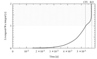
- the Livengood-Wu integral is a well-known method for predicting knocking. This method estimates the ignition delay time when the pressure and temperature in the combustion chamber are changed, and integrates it over time. When the time integral value reaches "1", autoignition, or knocking, occurs.
- the Livengood-Wu integral is widely used in the design of actual engines, as shown in Patent Documents 1 and 2 below.
- the "Livengood-Wu integral" is a simple method that can predict the occurrence of knocking (autoignition) to a certain extent, but the accuracy of the prediction is not necessarily sufficient. In order to make the most of the capabilities of the internal combustion engine as a power generation device, it is highly desirable to establish a knocking prediction method with higher accuracy than the "Livengood-Wu integral.”
- the present disclosure has been made in consideration of the above-mentioned circumstances, and aims to provide a knocking prediction method and device, an engine control device, and a vehicle that can further improve accuracy.
- the present disclosure aims to provide a design method for a combustion device, a power generating device, a vehicle, and a fuel that can improve the substantial performance of the fuel.
- the knocking prediction method is a knocking prediction method for predicting knocking that may occur in a premixed combustion field, and predicts knocking based on the knowledge that in the premixed combustion field, the temporal changes in normalized fuel mass fraction and normalized temperature in zero-dimensional homogeneous ignition are equivalent to the spatial changes in a one-dimensional laminar premixed flame.
- the knocking prediction method is a knocking prediction method for predicting knocking that may occur in a premixed combustion field, and in a characteristic diagram showing the relationship between normalized temperature and normalized fuel mass fraction of the fuel, a fuel with a Lewis number greater than 1 is deemed to have a possibility of knocking, and a fuel with a Lewis number less than 1 is deemed to have no possibility of knocking.
- the knocking prediction method is a knocking prediction method for predicting knocking that may occur in a premixed combustion field, and includes a calculation step for sequentially calculating the combustion speed when the inlet temperature is gradually increased by one-dimensional steady-state analysis of the premixed combustion field, a determination step for determining whether the combustion speed cannot be obtained because a flame cannot exist in the premixed combustion field, and an occurrence condition acquisition step for acquiring the inlet temperature corresponding to the last acquired combustion speed as the occurrence condition of the knocking.
- the knocking prediction method according to the fourth aspect of the present disclosure is the knocking prediction method according to the third aspect, in which the calculation step calculates the size of the area including the unburned mixture, the flame reaction zone, and the burned gas in the premixed combustion field by reducing it to the limit that the flame can contain.
- the knocking prediction method according to the fifth aspect of the present disclosure is the knocking prediction method according to the third or fourth aspect, which predicts fuels with Lewis numbers greater than 1.
- the knocking prediction device is a knocking prediction device that predicts knocking that may occur in a premixed combustion field, and includes a calculation means that sequentially calculates the combustion speed when the inlet temperature is gradually increased by one-dimensional steady-state analysis of the premixed combustion field, a determination means that determines whether the combustion speed cannot be obtained because a flame cannot exist in the premixed combustion field, and an occurrence condition acquisition means that acquires the inlet temperature corresponding to the last acquired combustion speed as the occurrence condition of the knocking.
- the knocking prediction device is the knocking prediction device according to the first aspect, in which the calculation means calculates the size of the area including the unburned mixture, the flame reaction zone, and the burned gas in the premixed combustion field by reducing it to the limit that can be contained by the flame.
- the knocking prediction device is the knocking prediction device according to the first or second aspect, in which the calculation means calculates fuels with Lewis numbers greater than 1.
- the engine control device includes a knocking prediction device according to the first or second aspect, and generates an engine control signal based on the knocking prediction result of the knocking prediction device.
- the engine control device is the engine control device according to the first aspect, further comprising a communication device capable of freely communicating with the outside, and transmits at least the knocking prediction result and the engine operation amount indicated by the engine control signal to the outside using the communication device.
- the engine control device is the engine control device according to the second aspect, which transmits engine control variables and other engine-related information other than the engine control variables and the engine operation variables to the outside.
- the vehicle according to the first aspect of the present disclosure includes an engine control device according to the first or second aspect, and an engine controlled by the engine control device.
- the method for designing a combustion device according to the first aspect of the present disclosure is to design a combustion device based on the knocking occurrence conditions estimated based on the knocking prediction method according to the third or fourth aspect.
- the method for designing a power generating device according to the first aspect of the present disclosure is to design a power generating device based on the knocking occurrence conditions estimated based on the knocking prediction method according to the third or fourth aspect.
- the vehicle design method according to the first aspect of the present disclosure is to design a vehicle based on the knocking occurrence conditions estimated based on the knocking prediction method according to the third or fourth aspect.
- the fuel design method according to the first aspect of the present disclosure is to design the fuel based on the knocking occurrence conditions estimated based on the knocking prediction method according to the third or fourth aspect.
- a knocking prediction method it is possible to provide a knocking prediction method, a knocking prediction device, a combustion device design method, a power generation device design method, a vehicle design method, and a fuel design method that can further improve accuracy. Furthermore, according to the present disclosure, it is possible to provide a design method for a combustion device, a power generating device, a vehicle, and a fuel, which are capable of improving the substantial performance of the fuel.
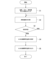
- FIG. 4 is a flowchart illustrating a knock prediction method according to an embodiment of the present disclosure.
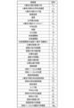
- 1 is a block diagram showing a functional configuration of a knocking prediction device according to an embodiment of the present disclosure. 1 is a list of various physical quantities used in the theoretical explanation of an embodiment of the present disclosure.
- FIG. 4 is a first characteristic diagram showing a knocking prediction characteristic in the embodiment of the present disclosure.
- FIG. 4 is a second characteristic diagram showing a knocking prediction characteristic in the embodiment of the present disclosure.
- FIG. 11 is a third characteristic diagram showing a knocking prediction characteristic in the embodiment of the present disclosure.
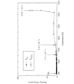
- FIG. 4 is a characteristic diagram showing a comparative example of a knocking prediction method according to an embodiment of the present disclosure.
- 1 is a block diagram showing an engine control device and a vehicle according to an embodiment of the present disclosure.
- FIG. 2 is a schematic diagram illustrating external communication of a vehicle according to an embodiment of the present disclosure.
- FIG. 1 is a flowchart showing a knocking prediction method according to the present embodiment.
- This flowchart shows a procedure for acquiring a flame propagation limit temperature, which is a condition for the occurrence of knocking, that is, an initial temperature at which knocking occurs, for a premixed combustion field (combustion chamber) in which a premixed mixture of fuel and air (oxidizer) is ignited by a compulsory means such as spark ignition and combusted.
- This flowchart also shows an overview of the processing steps of a knocking prediction program (simulation program) executed by a specific computer.
- the knocking prediction method according to this embodiment is realized by information processing (simulation) using a computer.
- the computer that executes the knocking prediction method according to this embodiment i.e., the computer on which the knocking prediction program is installed, is the knocking prediction device according to this embodiment.
- the knocking prediction device according to this embodiment is a device that outputs the conditions for knocking to occur in a premixed combustion field by executing the knocking prediction program.
- FIG. 2 is a block diagram showing the functional configuration of the knocking prediction device A according to this embodiment.
- the knocking prediction device A includes at least a storage unit 1 that stores a knocking prediction program in advance, a calculation unit 2 that executes the knocking prediction program, an operation unit 3 that inputs an operator's operation instructions to the calculation unit 2, and an output unit 4 that outputs the calculation result of the calculation unit 2, i.e., the above-mentioned flame propagation limit temperature (initial temperature), to the outside.
- the above-mentioned flame propagation limit temperature initial temperature
- memory unit 1, calculation unit 2, and operation unit 3 constitute the calculation means in this disclosure. Details will be described later, but memory unit 1, calculation unit 2, and operation unit 3 work together to sequentially calculate the combustion speed when the inlet temperature is gradually increased by one-dimensional steady-state analysis of the premixed combustion field.
- the memory unit 1, the calculation unit 2, and the operation unit 3 in the knocking prediction device A constitute the determination means in this disclosure. That is, the memory unit 1, the calculation unit 2, and the operation unit 3 work together to determine whether or not it has become impossible to obtain the combustion speed because a flame can no longer exist in the premixed combustion field.
- the memory unit 1, the calculation unit 2, and the operation unit 3 in the knocking prediction device A constitute the occurrence condition acquisition means in this disclosure. That is, the memory unit 1, the calculation unit 2, and the operation unit 3 cooperate to acquire the inlet temperature (flame propagation limit temperature) corresponding to the last acquired combustion speed as the occurrence condition of knocking.
- the calculation means of the knocking prediction device A according to this embodiment corresponds to the calculation step in the knocking prediction method according to this embodiment.
- the determination means of the knocking prediction device A according to this embodiment corresponds to the determination step in the knocking prediction method according to this embodiment.
- the raw condition acquisition means of the knocking prediction device A according to this embodiment corresponds to the occurrence condition acquisition step in the knocking prediction method according to this embodiment.
- the premixed combustion field in this embodiment is a combustion field that corresponds to the combustion chamber of an internal combustion engine (prime mover), such as a gasoline engine installed in a vehicle as a power generating device.
- an internal combustion engine such as a gasoline engine installed in a vehicle as a power generating device.
- measures such as lowering the compression ratio are taken to prevent knocking, that is, to prevent spontaneous ignition of unburned gas.
- the above-mentioned internal combustion engine includes direct injection engines and engines with a pre-chamber.
- the knocking prediction method according to this embodiment relates to a design method for a combustion device equipped with a premixed combustion field (combustion chamber), a power generating device (prime mover), a vehicle, etc. Furthermore, the knocking prediction method according to this embodiment also relates to a design method for a fuel that burns in a premixed combustion field.
- the knocking prediction method is based on the premise that when a time-space transformation of a flame is applied to a premixed combustion field, the temporal changes in normalized fuel mass fraction and normalized temperature in zero-dimensional homogeneous ignition are equivalent to the spatial changes in a one-dimensional laminar premixed flame.
- this knocking prediction method is based on the theoretical basis of the equivalence between the temporal changes in normalized fuel mass fraction and normalized temperature in zero-dimensional homogeneous ignition and the spatial changes in one-dimensional laminar premixed flames.
- the change in flame propagation over time is about the same magnitude as the compressed premixed mixture or shock waves in a premixed combustion field. It is also clear that the Lewis number of the fuel in a premixed combustion field is a physical quantity that determines the existence of a premixed flame structure.
- FIG. 3 is a table listing the various physical quantities used in the following theoretical explanation.
- Equation (1) and (2) are the governing equations for zero-dimensional homogeneous ignition using normalized fuel mass fraction and temperature. These governing equations (1) and (2) are the conservation laws of energy and chemical species under constant pressure and constant enthalpy, and are given by the mass fraction of the kth species, the chemical production rate of the kth species, the molecular weight of the kth species, the mass density, the temperature, the total number of chemical species, the enthalpy of the kth species, the average specific heat, and time.
- the mass density is given by the gas equation of state used for the interconversion of pressure, density, and temperature, as shown in the following equation (3). Note that R in this equation of state (3) is the universal gas constant.
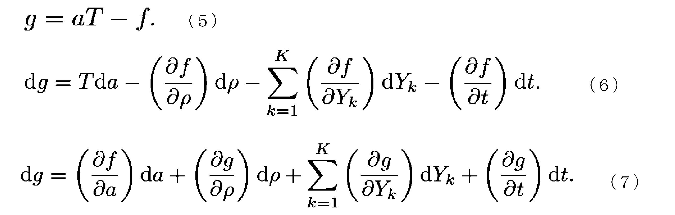
- equation (5) the multivariate function g shown in equation (5) below is obtained.
- the total differential of this multivariate function g is expressed as equation (6) below, with the variables being a, mass density, mass fraction, and time.
- the total differential of the multivariate function g is then expressed as equation (7) below based on equation (6).
- equation (8) is obtained based on a comparison between equation (6) and equation (7). Furthermore, since equation (5) above can be defined as shown in equation (9), the relationship shown in equation (10) holds between multivariate function f and multivariate function g.
- a candidate for the multivariate function f in equations (8) and (10) is the normalized temperature.
- a candidate for the multivariate function g can be the normalized fuel mass fraction in the case of the single-step chemical reaction model in equation (8), or the normalized progress variable in the case of the multi-step chemical reaction model in equation (10).
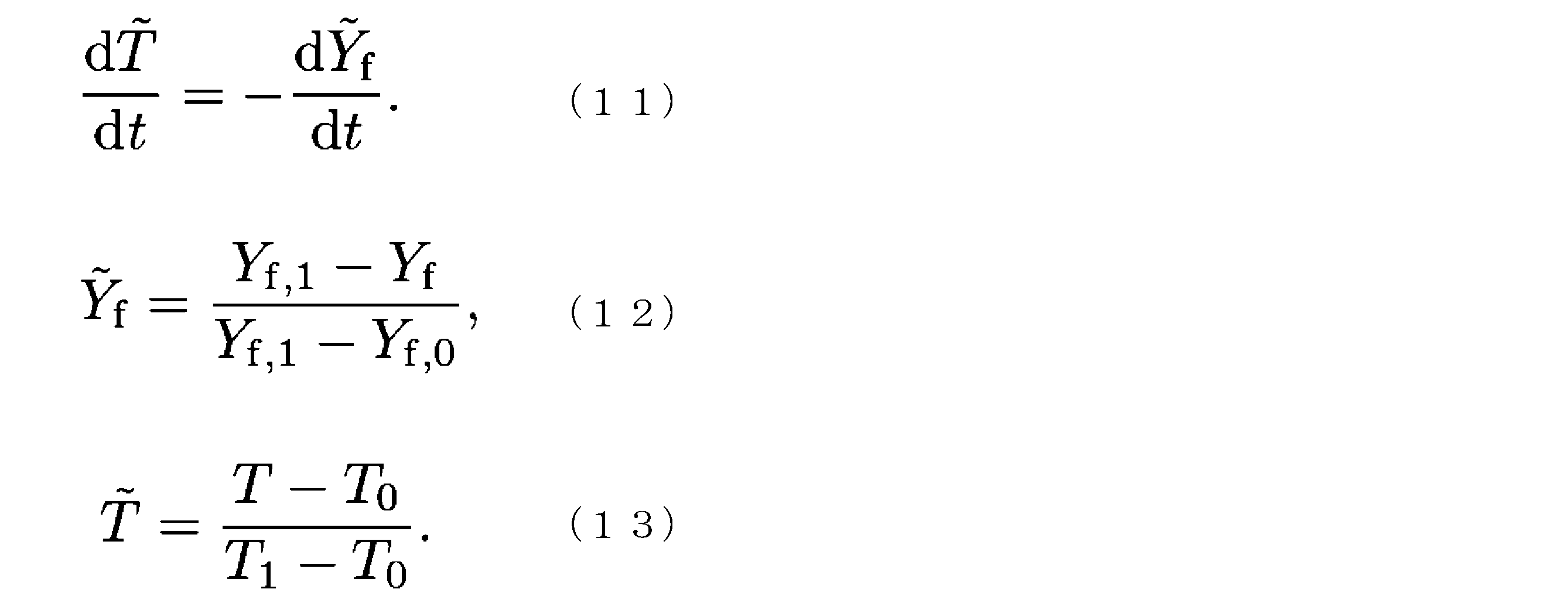
- the above equation (8) is expressed as the following equation (11), which shows the relationship between the time change of the normalized temperature and the time change of the normalized fuel mass fraction.
- the normalized temperature is defined by the following equation (12), which has the initial temperature and final temperature as parameters.
- the normalized fuel mass fraction is defined by the following equation (13), which has the initial fuel mass fraction and final fuel mass fraction as parameters.
- the normalized temperature, normalized fuel mass fraction, and normalized progress variable must be convex functions, and the total derivative of the normalized temperature must be greater than 0, the total derivative of the normalized fuel mass fraction must be less than 0, and the total derivative of the normalized progress variable must be greater than 0.
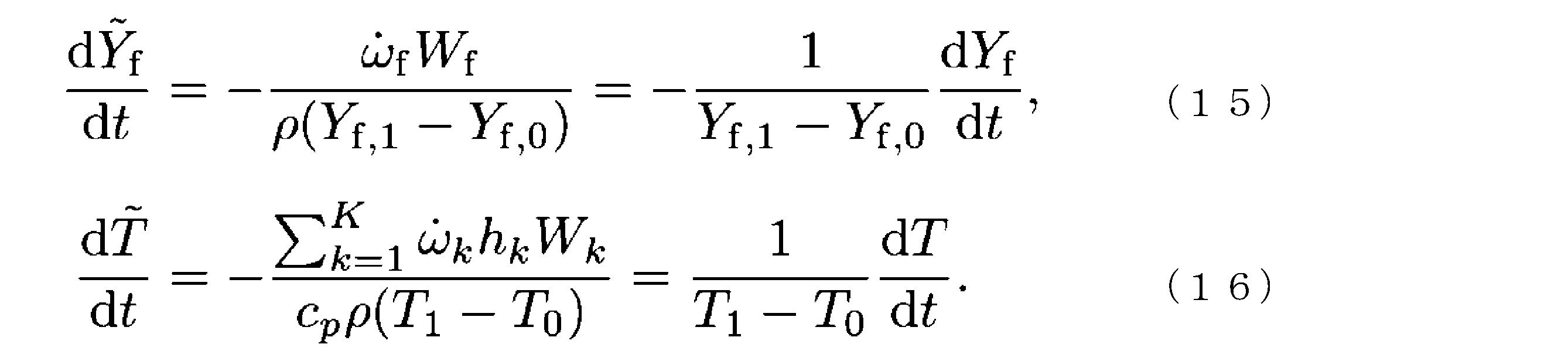
- the normalized fuel mass fraction is taken as the multivariate function g, and the signs of the normalized progress variables are simply inverted. Once either the normalized temperature or the normalized fuel mass fraction is determined, all remaining variables are determined. Based on this premise, equations (1) and (2) can be rewritten as the following equations (15) and (16) using the normalized temperature and normalized fuel mass fraction.
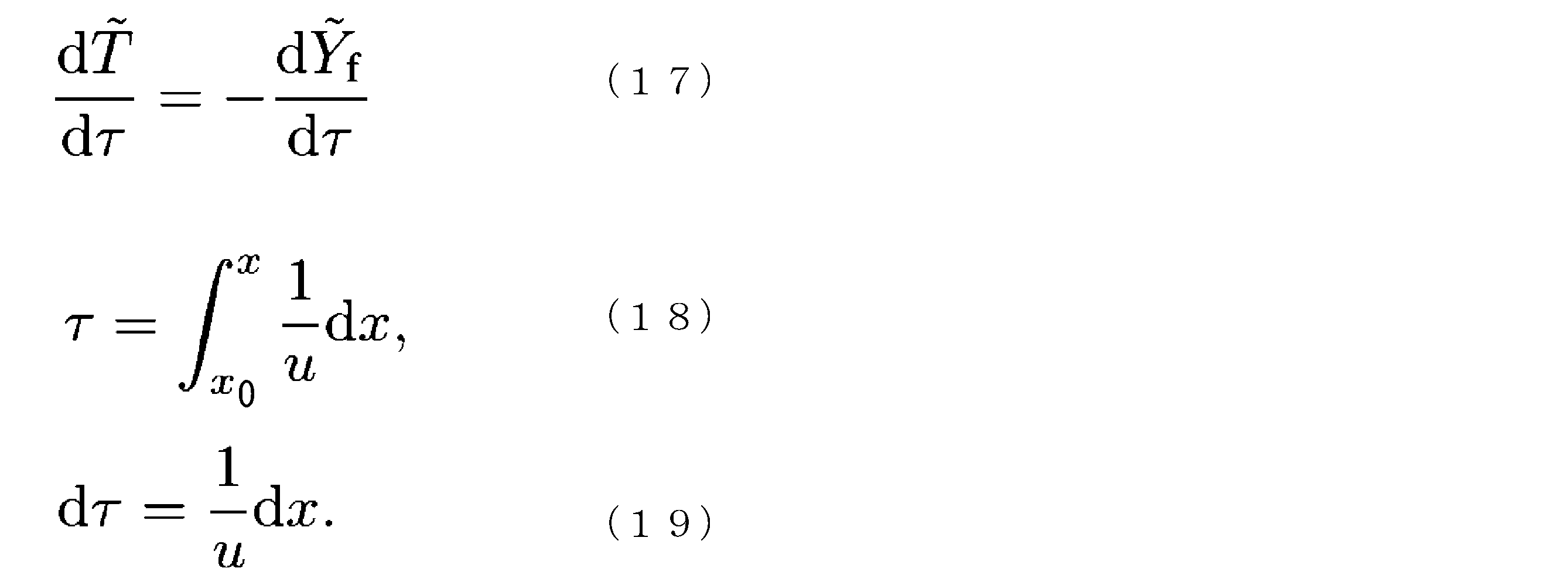
- equation (11) the relationship between normalized temperature and normalized fuel mass fraction is independent of time. Therefore, equation (11) can be rewritten using residence time as follows. Note that residence time is defined by equation (18) below, which consists of the velocity of the fluid parcel and the position of the fluid parcel, and is the total time that the fluid parcel spends within the control volume. The total derivative of such residence time is expressed by equation (19) below.
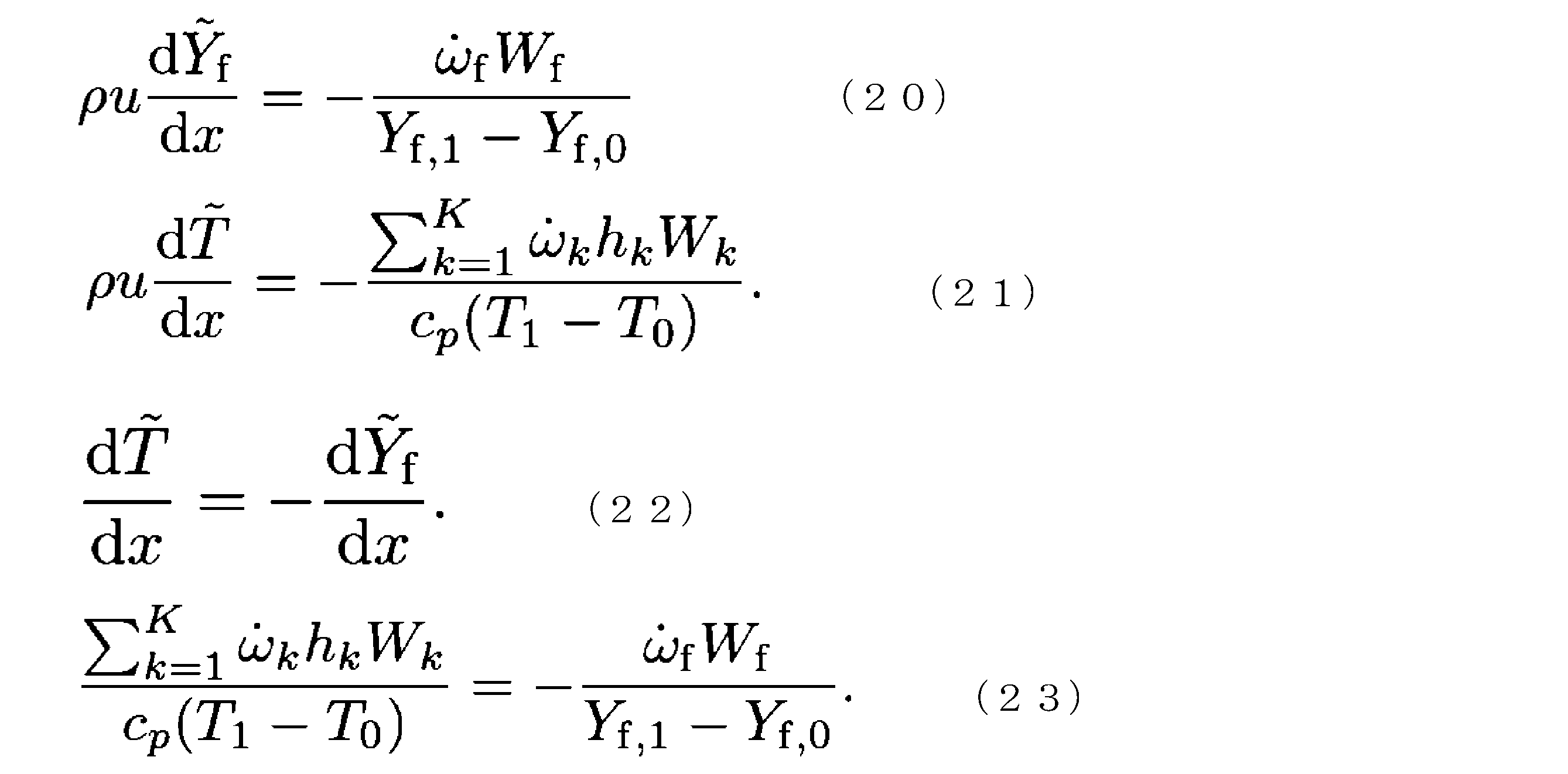
- equations (15) and (16) are transformed using equation (19), the following equations (20) and (21) are obtained. Furthermore, equation (17) can be rewritten as the following equation (22) using the parcel's position. Furthermore, the relationship shown in equation (23) holds based on equation (22).
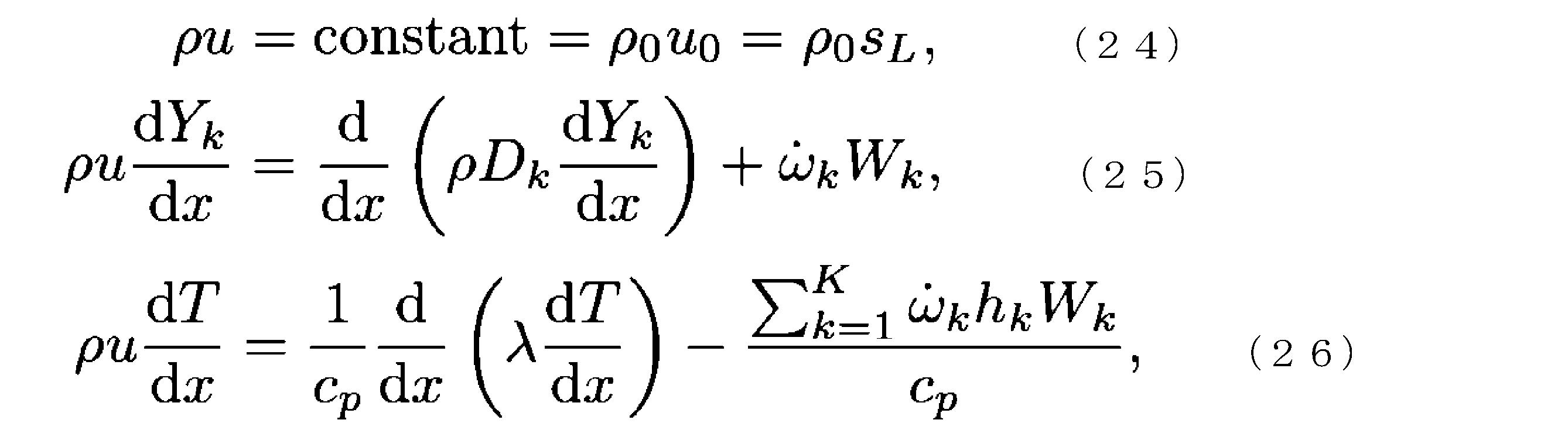
- equations (24) to (26) consisting of the laminar burning velocity, the mixing diffusion coefficient of the kth species, and the thermal conductivity of the premixed gas.
- equations (25) and (26) can be rewritten as the following equations (27) and (28) using the normalized temperature and normalized fuel mass fraction.
- equation (29) By substituting equations (22) and (23) into equation (27), we obtain the following equation (29). As can be seen by comparing equation (29) with equation (28), the only difference between the two equations is the first term on the right-hand side.
- the Lewis number of the fuel is defined by the following equation (30). Comparing equations (28) and (29) with a focus on this Lewis number, it can be seen that both equations are equivalent when the Lewis number is 1. In other words, for a fuel with a Lewis number of 1, the temporal changes in the normalized fuel mass fraction and normalized temperature in zero-dimensional homogeneous ignition are equivalent to the spatial changes in a one-dimensional laminar premixed flame.
- Figure 4 is a characteristic diagram showing the relationship between zero-dimensional homogeneous ignition and one-dimensional laminar premixed flame in a premixed combustion field when hydrogen, methane, propane and SNIa are used as fuel.
- SNIa represents the carbon state in the nuclear combustion process of Type Ia supernova and has a very high Lewis number.
- Hydrogen, methane and propane have Lewis numbers of 0.36, 0-96 and 1.95.
- zero-dimensional homogeneous ignition as indicated by the normalized fuel mass fraction and normalized temperature, is equivalent to a one-dimensional laminar premixed flame, as indicated by the normalized fuel mass fraction and normalized temperature.
- the profile of a one-dimensional laminar premixed flame is downwardly convex compared to the profile of a fuel with a Lewis number of 1 (zero-dimensional homogeneous ignition).
- the profile is convex above the profile for fuels with Lewis numbers of 1 (zero-dimensional homogeneous ignition) and may intersect with the profile for fuels with Lewis numbers of 1 (zero-dimensional homogeneous ignition) in the high temperature regions (reaction zones) of the flame where heat release is high.
- the consumption of the normalized fuel mass fraction at a given normalized temperature can be considered as the progress of the combustion reaction.
- the progress of the combustion reaction is in the following order: fuel with a Lewis number less than 1, fuel with a Lewis number of 1 (zero-dimensional homogeneous ignition), and fuel with a Lewis number greater than 1.
- gasoline one of the fuels, has a Lewis number greater than 1, so it is expected that self-ignition (knocking) will occur whenever the unburned gas region rises to a temperature and pressure that makes flame propagation impossible.
- the characteristic time of the flame behind the shock wave is similar to that at the time of ignition, which can affect the transition from flame propagation to detonation.
- gasoline since gasoline has a Lewis number greater than 1, there may be an area behind the shock wave where flame propagation is not possible.
- the normalized temperature and normalized fuel mass fraction must be convex functions in order to maintain the Legendre transformation, so the calculation domain must be as short as possible. Therefore, in this simulation, the size of the domain containing the unburned mixture, the flame reaction zone, and the burned gas in the premixed combustion field is set to the smallest limit that can contain the flame.
- the numerical conditions (initial conditions) for the pressure and equivalence ratio are fixed values, for example, 0.1 MPa and 1.0.
- Such a simulation corresponds to the knocking prediction method according to this embodiment. Furthermore, this simulation is the processing operation of the knocking prediction device according to this embodiment, that is, information processing executed by the calculation unit 2 based on the knocking prediction program pre-stored in the storage unit 1.
- the operator first operates the operation unit 3 to input the initial conditions required for the simulation, such as temperature, pressure, and the type of fuel, such as hydrogen fuel or n-heptane fuel, and the equivalence ratio, into the calculation unit 2 (step S1).
- the initial conditions required for the simulation such as temperature, pressure, and the type of fuel, such as hydrogen fuel or n-heptane fuel, and the equivalence ratio
- Calculation unit 2 uses the temperature, pressure, fuel type, and equivalence ratio input in step S1 and gradually increases the inlet temperature (calculation start temperature) to perform a one-dimensional steady-state analysis (calculation process) to calculate the flame propagation limit temperature for each fuel (step S2).
- This one-dimensional steady-state analysis is a convergence calculation that shrinks the flame front and flame rear until the one-dimensional premixed flame structure becomes the narrowest calculation region that results in a unique solution.
- the calculation unit 2 sequentially calculates the burning velocity when the inlet temperature is gradually increased using a one-dimensional steady-state analysis of the premixed combustion field, but the burning velocity calculation may converge or diverge depending on the set value of the inlet temperature.
- the calculation unit 2 performs a convergence judgment (judgment process) for each calculation of the burning rate for a certain inlet temperature (calculation start temperature) (step S3). That is, in step S3, the calculation unit 2 judges whether or not the burning rate cannot be obtained because a flame can no longer exist in the premixed combustion field. Then, if the judgment result in step S3 is "convergence," the calculation unit 2 sets the inlet temperature even higher and executes the burning rate calculation.
- step S4 occurrence condition acquisition process.
- the calculation unit 2 acquires the flame propagation limit temperature (inlet temperature) corresponding to the last acquired combustion speed as the occurrence condition for knocking.
- the calculation unit 2 then outputs the simulation result including the flame propagation limit temperature acquired in this manner as the occurrence condition for knocking to the output unit 4.
- Figure 5 shows an example of this simulation result (one-dimensional steady-state analysis result), that is, a calculation result including the knocking occurrence conditions that is output by the calculation unit 2 to the output unit 4.
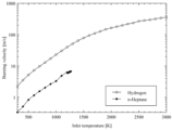
- Figure 6 shows an example of the relationship between the inlet temperature and the combustion speed of the premixed combustion field based on such a simulation result.
- the black circles are the simulation results in this embodiment (one-dimensional steady-state analysis result), and the squares are the results of direct numerical simulation (DNS) shown as a comparative example.
- DMS direct numerical simulation
- Figure 6 shows that for hydrogen fuel, the burning rate increases with increasing inlet or initial temperature, and a propagating flame exists even at an inlet temperature of 3000 K.
- Figure 6 also shows that for n-heptane fuel, the burning rate increases with increasing inlet temperature, but a propagating flame cannot exist above 1270 K.
- the theoretical basis for this embodiment is that it theoretically shows that the relationship between normalized fuel mass fraction and normalized temperature is equivalent for zero-dimensional homogeneous ignition and one-dimensional laminar premixed flames, whose Lewis number after space-time transformation is 1, and that the Lewis number is a physical quantity that determines the existence of a premixed flame structure near the explosive transition of the flame in a premixed combustion field.
- Figure 7 shows a comparative example of this embodiment.
- this comparative example is the result of calculating the "Livengood-Wu integral" using direct numerical simulation (DNS).
- DNS direct numerical simulation
- the "Livengood-Wu integral” causes auto-ignition (knocking) when the time integral value becomes 1.
- this embodiment is based on the knowledge that for a fuel with a Lewis number of 1, the temporal changes in normalized fuel mass fraction and normalized temperature in zero-dimensional homogeneous ignition are equivalent to the spatial changes in a one-dimensional laminar premixed flame, and therefore has higher accuracy than the "Livengood-Wu integral.”
- this embodiment can provide a knocking prediction method and knocking prediction device that can further improve accuracy.
- knocking prediction method and knocking prediction device have high knocking prediction accuracy, which provides great benefits to the design of combustion devices, power generation devices (internal combustion engines), vehicles, fuels, etc.
- the knocking prediction method and knocking prediction device make it possible to estimate the margin for knocking that should be considered in the design of combustion devices, power generating devices, vehicles, etc. more narrowly than ever before.
- the knocking prediction method and knocking prediction device can provide a method for designing a combustion device, a method for designing a power generation device, and a method for designing a vehicle that can improve the performance of a combustion device, a power generation device, a vehicle, etc.
- the knocking prediction method and knocking prediction device can predict knocking with high accuracy for each type of fuel, which can contribute to the design of fuels that avoid knocking. Therefore, the knocking prediction method and knocking prediction device according to this embodiment can provide a fuel setting method that can improve the performance of the fuel.
- this embodiment predicts knocking of the fuel to be evaluated based on a one-dimensional steady-state analysis (simulation) of the fuel to be evaluated. Therefore, this disclosure is not limited to pure-substance fuels, but can be applied to multi-substance fuels that are mixtures of multiple components, as long as one-dimensional steady-state analysis (simulation) is possible.
- fuels for which chemical species and elementary reactions have been identified include surrogate fuels consisting of up to five components defined in the SIP (Innovative Combustion Technology) surrogate chemical reaction mechanism.
- SIP Innovative Combustion Technology
- chemical species and elementary reactions have not yet been identified for multi-substance fuels consisting of six or more components.
- the engine control device is an ECU (Electronic Control Unit) 11 shown in FIG. 8.
- the vehicle according to this embodiment is an automobile M equipped with a vehicle operation device 10, an ECU 11, an engine 12, and a communication device 13, as also shown in FIG. 8.
- the vehicle operation device 10 is an operation panel of the automobile M, which generates an operation instruction signal based on the input operation of the driver and outputs it to the ECU 11.
- the operation instruction signal is a signal that indicates the driver's operation instruction for the automobile M.
- the ECU 11 is a so-called embedded computer, and includes an arithmetic circuit, a memory circuit, and an input/output circuit.
- the ECU 11 controls the engine 12 by executing an engine control program that is pre-stored in the memory circuit.
- the ECU 11 generates various engine control signals by executing an engine control program in an arithmetic circuit.
- These engine control signals are signals that indicate various operation amounts (engine operation amounts) for the engine 12, such as the opening degree of the air intake valve and the opening degree and timing of the fuel injection valve.
- the ECU 11 controls the engine 12 by outputting such engine control signals to the engine 12 using an input/output circuit.
- the engine 12 is an internal combustion engine that generates power by burning fuel in a combustion chamber, and is equipped with a sensor group 12a consisting of multiple sensors.
- This sensor group 12a detects various state quantities related to the engine 12 as engine control quantities, such as the opening degree of the air intake valve, the operation of the fuel injection valve, and the carbon dioxide contained in the exhaust gas, and outputs these engine control quantities to the ECU 11 as sensor signals.
- the ECU 11 When generating the engine control signal, the ECU 11 refers to the operation instruction signal input from the vehicle operation device 10 and various sensor signals input from the sensor group 12a. The ECU 11 generates the engine control signal (engine operation amount) by processing the operation instruction signal and engine control amount according to an engine control program.
- the ECU 11 in this embodiment also includes the above-mentioned knocking prediction device A, as shown in FIG. 8.
- the knocking prediction device A is a computer that predicts the occurrence of knocking by executing, in the calculation unit 2, a knocking prediction program that is pre-stored in the storage unit 1, as described above.
- knocking prediction device A in ECU 11 derives the fuel composition from big data based on information already collected from surrounding vehicles using date, time and location information, and obtains the knocking occurrence prediction result by executing a knocking prediction program on that fuel composition.
- the timing for obtaining the knocking occurrence prediction result is immediately after fuel is refueled into automobile M and before automobile M starts to drive.
- the fuel composition is constantly updated based on the driving conditions while automobile M is driving, and when there is a large deviation from the initially predicted fuel composition, the knocking occurrence prediction result is also updated.
- the updated information is transmitted by data communication such as wirelessly, and is stored as big data that is useful for surrounding vehicles and for development and improvement.
- the ECU 11 is an embedded computer that includes the knocking prediction device A as an additional function associated with the engine control function by pre-storing a knocking prediction program in addition to the engine control program.
- Such an ECU 11 refers to the knocking prediction results obtained by executing the knocking prediction program when generating an engine control signal. For example, when the occurrence of knocking is predicted by executing the knocking prediction program, the ECU 11 generates an engine control signal to avoid knocking.
- the ECU 11 provides the knocking prediction results based on the knocking prediction program, the engine operation amount indicated by the engine control signal, and the engine control amount obtained by the sensor group 12a, together with additional information, to an external data collection device D.
- the additional information is engine-related information other than the engine control amount and the engine operation amount, such as the date, time, outside temperature, season, fuel composition, and the traveling position of the automobile M.
- the ECU 11 sequentially stores in the memory circuit as learning data (time-series data) the knocking prediction results obtained before the vehicle M starts to move, and the engine operation amounts, engine control amounts, and associated information obtained in chronological order while the vehicle M is moving.
- the ECU 11 reads out such learning data from the memory circuit at a predetermined timing and outputs it to the communication device 13.
- the communication device 13 is a wireless communication device that is provided between the ECU 11 and the data collection device D and mediates communication between the ECU 11 and the data collection device D. In other words, the communication device 13 converts the learning data input from the ECU 11 into a wireless signal and transmits it to the data collection device D.
- such learning data is provided to the data collection device D from multiple automobiles M1 to Mn (n: a natural number of 2 or more) equipped with an ECU 11 incorporating a knocking prediction device A.
- the data collection device D sequentially accumulates learning data related to multiple automobiles M1 to Mn as big data.
- This kind of big data can be used in a variety of ways, as each learning data item contains knocking prediction results corresponding to engine operation amounts, engine control amounts, and additional information.
- knocking is avoided by switching to the motor under conditions that would cause knocking, or by increasing motor assist, and the big data in this embodiment can be useful data for considering designs to avoid such knocking.
- the present invention makes it possible to omit this data collection and input process during automobile manufacturing. Furthermore, if an automobile is equipped with the functions of the present invention, the knocking suppression effect can be achieved without going through the process of inputting data in advance, even for new fuel compositions such as e-fuel that will be released after the sale. Furthermore, when a sub-chamber is provided in the combustion chamber of the engine 12, it is possible to flexibly control ignition properties, thereby improving thermal efficiency.
- the present disclosure can be used in knocking prediction methods, knocking prediction devices, engine control devices, vehicles, combustion device design methods, power generation device design methods, vehicle design methods, and fuel design methods.
- a Knocking prediction device D Data collection device M Automobile (vehicle) REFERENCE SIGNS LIST 1 Memory unit 2 Calculation unit 3 Operation unit 4 Output unit 10 Vehicle operation device 11 ECU (engine control unit) 12 engine 12a sensor group 13 communication device
Landscapes
- Engineering & Computer Science (AREA)
- Chemical & Material Sciences (AREA)
- Combustion & Propulsion (AREA)
- Mechanical Engineering (AREA)
- General Engineering & Computer Science (AREA)
- Combined Controls Of Internal Combustion Engines (AREA)
Abstract
Description
また、本開示は、燃焼装置、動力発生装置、車両の設計方法及び燃料の実質的な性能を高めることが可能な燃焼装置の設計方法、動力発生装置の設計方法、車両の設計方法及び燃料の設計方法の提供を目的とする。
また、本開示によれば、燃焼装置、動力発生装置、車両の設計方法及び燃料の実質的な性能を高めることが可能な燃焼装置の設計方法、動力発生装置の設計方法、車両の設計方法及び燃料の設計方法を提供することが可能である。
図1は、本実施形態に係るノッキング予測方法を示すフローチャートである。このフローチャートは、燃料と空気(酸化剤)とからなる予混合気を火花点火のような強制的な手段により着火させることにより燃焼させる予混合燃焼場(燃焼室)について、ノッキングの発生条件である火炎伝播限界温度つまりノッキングが発生する初期温度の取得手順を示している。







D データ収集装置
M 自動車(車両)
1 記憶部
2 演算部
3 操作部
4 出力部
10 車両操作装置
11 ECU(エンジン制御装置)
12 エンジン
12a センサ群
13 通信装置
Claims (16)
- 予混合燃焼場で発生し得るノッキングを予測するノッキング予測方法であって、
前記予混合燃焼場において、ゼロ次元均質点火における正規化燃料質量分率及び正規化温度の時間的変化と1次元層流予混合火炎における空間的変化とが等価であるという知見に基づいてノッキングを予測するノッキング予測方法。 - 予混合燃焼場で発生し得るノッキングを予測するノッキング予測方法であって、
正規化温度と燃料の正規化燃料質量分率との関係を示す特性図において、ルイス数が1より大きい燃料を前記ノッキングの可能性があるとし、前記ルイス数が1より小さい燃料を前記ノッキングの可能性がないとするノッキング予測方法。 - 予混合燃焼場で発生し得るノッキングを予測するノッキング予測方法であって、
前記予混合燃焼場の1次元定常解析によって入口温度を徐々に増加させた場合の燃焼速度を順次計算する計算工程と、
前記予混合燃焼場に火炎が存在できなくなるために前記燃焼速度が取得不能になったか否かを判定する判定工程と、
最後に取得された前記燃焼速度に対応する前記入口温度を前記ノッキングの発生条件として取得する発生条件取得工程と
を有するノッキング予測方法。 - 前記計算工程では、前記予混合燃焼場における未燃混合気、火炎の反応帯及び既燃焼気体を含む領域の大きさを、火炎が包含できる限界まで小さくして計算する請求項3に記載のノッキング予測方法。
- ルイス数が1より大きい燃料を予測対象とする請求項3又は4に記載のノッキング予測方法。
- 予混合燃焼場で発生し得るノッキングを予測するノッキング予測装置であって、
前記予混合燃焼場の1次元定常解析によって入口温度を徐々に増加させた場合の燃焼速度を順次計算する計算手段と、
前記予混合燃焼場に火炎が存在できなくなるために前記燃焼速度が取得不能になったか否かを判定する判定手段と、
最後に取得された前記燃焼速度に対応する前記入口温度を前記ノッキングの発生条件として取得する発生条件取得手段と
を備えるノッキング予測装置。 - 前記計算手段は、前記予混合燃焼場における未燃混合気、火炎の反応帯及び既燃焼気体を含む領域の大きさを、火炎が包含できる限界まで小さくして計算する請求項6に記載のノッキング予測装置。
- 前記計算手段は、ルイス数が1より大きい燃料を計算対象とする請求項6又は7に記載のノッキング予測装置。
- 請求項3又は4に記載のノッキング予測方法に基づいて推定された前記ノッキングの発生条件に基づいて燃焼装置を設計する燃焼装置の設計方法。
- 請求項3又は4に記載のノッキング予測方法に基づいて推定された前記ノッキングの発生条件に基づいて動力発生装置を設計する動力発生装置の設計方法。
- 請求項3又は4に記載のノッキング予測方法に基づいて推定された前記ノッキングの発生条件に基づいて車両を設計する車両の設計方法。
- 請求項3又は4に記載のノッキング予測方法に基づいて推定された前記ノッキングの発生条件に基づいて燃料を設計する燃料の設計方法。
- 請求項6又は7に記載のノッキング予測装置を備え、
前記ノッキング予測装置のノッキング予測結果に基づいてエンジン制御信号を生成するエンジン制御装置。 - 外部との通信が自在な通信装置をさらに備え、
少なくとも前記ノッキング予測結果及び前記エンジン制御信号が示すエンジン操作量を前記通信装置を用いて外部に送信する請求項13に記載のエンジン制御装置。 - エンジン制御量に加え、該エンジン制御量及び前記エンジン操作量以外のエンジン関連情報を前記外部に送信する請求項14に記載のエンジン制御装置。
- 請求項13又は14に記載のエンジン制御装置と、
該エンジン制御装置によって制御されるエンジンと、
を備える車両。
Priority Applications (2)
| Application Number | Priority Date | Filing Date | Title |
|---|---|---|---|
| CN202480037229.4A CN121241194A (zh) | 2023-06-06 | 2024-05-31 | 爆震预测方法、爆震预测装置、发动机控制装置、车辆、燃烧装置的设计方法、动力产生装置的设计方法、车辆的设计方法以及燃料的设计方法 |
| JP2025526095A JPWO2024253047A1 (ja) | 2023-06-06 | 2024-05-31 |
Applications Claiming Priority (2)
| Application Number | Priority Date | Filing Date | Title |
|---|---|---|---|
| PCT/JP2023/020935 WO2024252510A1 (ja) | 2023-06-06 | 2023-06-06 | ノッキング予測方法、ノッキング予測装置、燃焼装置の設計方法、動力発生装置の設計方法、車両の設計方法及び燃料の設計方法 |
| JPPCT/JP2023/020935 | 2023-06-06 |
Publications (1)
| Publication Number | Publication Date |
|---|---|
| WO2024253047A1 true WO2024253047A1 (ja) | 2024-12-12 |
Family
ID=93795329
Family Applications (2)
| Application Number | Title | Priority Date | Filing Date |
|---|---|---|---|
| PCT/JP2023/020935 Ceased WO2024252510A1 (ja) | 2023-06-06 | 2023-06-06 | ノッキング予測方法、ノッキング予測装置、燃焼装置の設計方法、動力発生装置の設計方法、車両の設計方法及び燃料の設計方法 |
| PCT/JP2024/020120 Ceased WO2024253047A1 (ja) | 2023-06-06 | 2024-05-31 | ノッキング予測方法、ノッキング予測装置、エンジン制御装置、車両、燃焼装置の設計方法、動力発生装置の設計方法、車両の設計方法及び燃料の設計方法 |
Family Applications Before (1)
| Application Number | Title | Priority Date | Filing Date |
|---|---|---|---|
| PCT/JP2023/020935 Ceased WO2024252510A1 (ja) | 2023-06-06 | 2023-06-06 | ノッキング予測方法、ノッキング予測装置、燃焼装置の設計方法、動力発生装置の設計方法、車両の設計方法及び燃料の設計方法 |
Country Status (3)
| Country | Link |
|---|---|
| JP (1) | JPWO2024253047A1 (ja) |
| CN (1) | CN121241194A (ja) |
| WO (2) | WO2024252510A1 (ja) |
Families Citing this family (1)
| Publication number | Priority date | Publication date | Assignee | Title |
|---|---|---|---|---|
| CN119647344B (zh) * | 2024-12-17 | 2025-09-02 | 中国科学技术大学 | 一种基于进化算法的简化化学反应动力学模型构建方法 |
Citations (5)
| Publication number | Priority date | Publication date | Assignee | Title |
|---|---|---|---|---|
| JP2006200396A (ja) * | 2005-01-19 | 2006-08-03 | Hitachi Ltd | 内燃機関の点火時期制御装置および点火時期制御ロジック作成装置 |
| JP2007332934A (ja) * | 2006-06-19 | 2007-12-27 | Toyota Central Res & Dev Lab Inc | 火花点火式内燃機関の最適点火時期設定方法及び火花点火式内燃機関の最適点火時期設定装置 |
| JP2008031916A (ja) * | 2006-07-28 | 2008-02-14 | Toyota Motor Corp | 内燃機関の自着火予測装置 |
| CN112345259A (zh) * | 2020-10-20 | 2021-02-09 | 同济大学 | 一种基于爆震自识别的汽油机虚拟标定方法 |
| CN113673089A (zh) * | 2021-07-23 | 2021-11-19 | 东风汽车集团股份有限公司 | 一种发动机性能确定方法、装置以及电子设备 |
-
2023
- 2023-06-06 WO PCT/JP2023/020935 patent/WO2024252510A1/ja not_active Ceased
-
2024
- 2024-05-31 JP JP2025526095A patent/JPWO2024253047A1/ja active Pending
- 2024-05-31 CN CN202480037229.4A patent/CN121241194A/zh active Pending
- 2024-05-31 WO PCT/JP2024/020120 patent/WO2024253047A1/ja not_active Ceased
Patent Citations (5)
| Publication number | Priority date | Publication date | Assignee | Title |
|---|---|---|---|---|
| JP2006200396A (ja) * | 2005-01-19 | 2006-08-03 | Hitachi Ltd | 内燃機関の点火時期制御装置および点火時期制御ロジック作成装置 |
| JP2007332934A (ja) * | 2006-06-19 | 2007-12-27 | Toyota Central Res & Dev Lab Inc | 火花点火式内燃機関の最適点火時期設定方法及び火花点火式内燃機関の最適点火時期設定装置 |
| JP2008031916A (ja) * | 2006-07-28 | 2008-02-14 | Toyota Motor Corp | 内燃機関の自着火予測装置 |
| CN112345259A (zh) * | 2020-10-20 | 2021-02-09 | 同济大学 | 一种基于爆震自识别的汽油机虚拟标定方法 |
| CN113673089A (zh) * | 2021-07-23 | 2021-11-19 | 东风汽车集团股份有限公司 | 一种发动机性能确定方法、装置以及电子设备 |
Non-Patent Citations (2)
| Title |
|---|
| LAPALME DENIS; LEMAIRE ROMAIN; SEERS PATRICE: "Assessment of the method for calculating the Lewis number of H2/CO/CH4mixtures and comparison with experimental results", INTERNATIONAL JOURNAL OF HYDROGEN ENERGY, ELSEVIER, AMSTERDAM, NL, vol. 42, no. 12, 11 March 2017 (2017-03-11), AMSTERDAM, NL, pages 8314 - 8328, XP085008031, ISSN: 0360-3199, DOI: 10.1016/j.ijhydene.2017.01.099 * |
| YOUHI MORII; KAORU MARUTA: "What connects ignition and deflagration? -- On explosive transition of deflagration", ARXIV.ORG, CORNELL UNIVERSITY LIBRARY, 201 OLIN LIBRARY CORNELL UNIVERSITY ITHACA, NY 14853, 18 January 2023 (2023-01-18), 201 Olin Library Cornell University Ithaca, NY 14853, XP091415012 * |
Also Published As
| Publication number | Publication date |
|---|---|
| JPWO2024253047A1 (ja) | 2024-12-12 |
| CN121241194A (zh) | 2025-12-30 |
| WO2024252510A1 (ja) | 2024-12-12 |
Similar Documents
| Publication | Publication Date | Title |
|---|---|---|
| Lapuerta et al. | Autoignition of blends of n-butanol and ethanol with diesel or biodiesel fuels in a constant-volume combustion chamber | |
| Yıldız et al. | Zero-dimensional single zone engine modeling of an SI engine fuelled with methane and methane-hydrogen blend using single and double Wiebe Function: A comparative study | |
| Pourkhesalian et al. | Alternative fuel and gasoline in an SI engine: A comparative study of performance and emissions characteristics | |
| Irdmousa et al. | Data-driven modeling and predictive control of combustion phasing for RCCI engines | |
| Gravalos et al. | Detection of fuel type on a spark ignition engine from engine vibration behaviour | |
| Hu et al. | A study of liquid fuel injection and combustion in a constant volume vessel at diesel engine conditions | |
| Desantes et al. | Validity of the Livengood & Wu correlation and theoretical development of an alternative procedure to predict ignition delays under variable thermodynamic conditions | |
| Hann et al. | A Quasi-Dimensional SI Burn Rate Model for Predicting the Effects of Changing Fuel, Air-Fuel-Ratio, EGR and Water Injection | |
| WO2024252510A1 (ja) | ノッキング予測方法、ノッキング予測装置、燃焼装置の設計方法、動力発生装置の設計方法、車両の設計方法及び燃料の設計方法 | |
| Vidal et al. | Performance map of a LPG-diesel dual-fuel engine based on experimental and non-linear least squares determined wiebe function | |
| Machrafi et al. | The development and experimental validation of a reduced ternary kinetic mechanism for the auto-ignition at HCCI conditions, proposing a global reaction path for ternary gasoline surrogates | |
| Chin et al. | Development and validation of a reduced DME mechanism applicable to various combustion modes in internal combustion engines | |
| Tougri et al. | Knocking prediction in internal combustion engines via thermodynamic modeling: preliminary results and comparison with experimental data | |
| Zhang et al. | Reduced mechanism generation for methanol-based toluene reference fuel with combined reduction methods | |
| Nishii et al. | Study on automatic adaptation for Control-oriented model of advanced diesel engine | |
| Rublewski et al. | Modeling NO formation in spark ignition engines with a layered adiabatic core and combustion inefficiency routine | |
| Welscher et al. | A Detailed Reaction Kinetics-Based Calculation Tool for Internal Combustion Engine-Related Ignition Processes | |
| Fonseca et al. | Tuning the parameters of ECFM-3Z combustion model for CFD 3D simulation of a two valve engine fueled with ethanol | |
| Sadiq Al-Baghdadi | Development of a pre-ignition submodel for hydrogen engines | |
| Karim | The onset of knock in gas fuelled spark ignition engines prediction and experiment | |
| Voicu et al. | A numerical simulation of the influence of injection characteristics on performance and emissions of a tractor diesel engine | |
| Floweday | Two contrasting approaches to auto-ignition modelling for HCCI engines | |
| Prince | Development of an N-Propanol Mechanism and Its Application on HCCI Engine Simulations | |
| Irimescu et al. | Calibration of 0D/1D models based on OBD data for quick remapping of SI engine ECUs | |
| Zarghami et al. | Performance enhancement of spark ignition engines by using fractional order controller |
Legal Events
| Date | Code | Title | Description |
|---|---|---|---|
| 121 | Ep: the epo has been informed by wipo that ep was designated in this application |
Ref document number: 24819277 Country of ref document: EP Kind code of ref document: A1 |
|
| ENP | Entry into the national phase |
Ref document number: 2025526095 Country of ref document: JP Kind code of ref document: A |
|
| WWE | Wipo information: entry into national phase |
Ref document number: 2025526095 Country of ref document: JP |
|
| NENP | Non-entry into the national phase |
Ref country code: DE |
|
| 122 | Ep: pct application non-entry in european phase |
Ref document number: 24819277 Country of ref document: EP Kind code of ref document: A1 |