WO2024253043A1 - ガスケット - Google Patents
ガスケット Download PDFInfo
- Publication number
- WO2024253043A1 WO2024253043A1 PCT/JP2024/020072 JP2024020072W WO2024253043A1 WO 2024253043 A1 WO2024253043 A1 WO 2024253043A1 JP 2024020072 W JP2024020072 W JP 2024020072W WO 2024253043 A1 WO2024253043 A1 WO 2024253043A1
- Authority
- WO
- WIPO (PCT)
- Prior art keywords
- base
- gasket
- flow path
- hardness
- explosion
- Prior art date
- Legal status (The legal status is an assumption and is not a legal conclusion. Google has not performed a legal analysis and makes no representation as to the accuracy of the status listed.)
- Ceased
Links
Images



Classifications
-
- H—ELECTRICITY
- H01—ELECTRIC ELEMENTS
- H01M—PROCESSES OR MEANS, e.g. BATTERIES, FOR THE DIRECT CONVERSION OF CHEMICAL ENERGY INTO ELECTRICAL ENERGY
- H01M50/00—Constructional details or processes of manufacture of the non-active parts of electrochemical cells other than fuel cells, e.g. hybrid cells
- H01M50/30—Arrangements for facilitating escape of gases
- H01M50/35—Gas exhaust passages comprising elongated, tortuous or labyrinth-shaped exhaust passages
- H01M50/358—External gas exhaust passages located on the battery cover or case
-
- F—MECHANICAL ENGINEERING; LIGHTING; HEATING; WEAPONS; BLASTING
- F16—ENGINEERING ELEMENTS AND UNITS; GENERAL MEASURES FOR PRODUCING AND MAINTAINING EFFECTIVE FUNCTIONING OF MACHINES OR INSTALLATIONS; THERMAL INSULATION IN GENERAL
- F16J—PISTONS; CYLINDERS; SEALINGS
- F16J15/00—Sealings
- F16J15/02—Sealings between relatively-stationary surfaces
- F16J15/06—Sealings between relatively-stationary surfaces with solid packing compressed between sealing surfaces
- F16J15/064—Sealings between relatively-stationary surfaces with solid packing compressed between sealing surfaces the packing combining the sealing function with other functions
-
- F—MECHANICAL ENGINEERING; LIGHTING; HEATING; WEAPONS; BLASTING
- F16—ENGINEERING ELEMENTS AND UNITS; GENERAL MEASURES FOR PRODUCING AND MAINTAINING EFFECTIVE FUNCTIONING OF MACHINES OR INSTALLATIONS; THERMAL INSULATION IN GENERAL
- F16J—PISTONS; CYLINDERS; SEALINGS
- F16J15/00—Sealings
- F16J15/02—Sealings between relatively-stationary surfaces
- F16J15/06—Sealings between relatively-stationary surfaces with solid packing compressed between sealing surfaces
- F16J15/10—Sealings between relatively-stationary surfaces with solid packing compressed between sealing surfaces with non-metallic packing
- F16J15/102—Sealings between relatively-stationary surfaces with solid packing compressed between sealing surfaces with non-metallic packing characterised by material
-
- F—MECHANICAL ENGINEERING; LIGHTING; HEATING; WEAPONS; BLASTING
- F16—ENGINEERING ELEMENTS AND UNITS; GENERAL MEASURES FOR PRODUCING AND MAINTAINING EFFECTIVE FUNCTIONING OF MACHINES OR INSTALLATIONS; THERMAL INSULATION IN GENERAL
- F16J—PISTONS; CYLINDERS; SEALINGS
- F16J15/00—Sealings
- F16J15/02—Sealings between relatively-stationary surfaces
- F16J15/06—Sealings between relatively-stationary surfaces with solid packing compressed between sealing surfaces
- F16J15/10—Sealings between relatively-stationary surfaces with solid packing compressed between sealing surfaces with non-metallic packing
- F16J15/104—Sealings between relatively-stationary surfaces with solid packing compressed between sealing surfaces with non-metallic packing characterised by structure
-
- H—ELECTRICITY
- H01—ELECTRIC ELEMENTS
- H01M—PROCESSES OR MEANS, e.g. BATTERIES, FOR THE DIRECT CONVERSION OF CHEMICAL ENERGY INTO ELECTRICAL ENERGY
- H01M50/00—Constructional details or processes of manufacture of the non-active parts of electrochemical cells other than fuel cells, e.g. hybrid cells
- H01M50/10—Primary casings; Jackets or wrappings
- H01M50/183—Sealing members
- H01M50/19—Sealing members characterised by the material
- H01M50/193—Organic material
-
- H—ELECTRICITY
- H01—ELECTRIC ELEMENTS
- H01M—PROCESSES OR MEANS, e.g. BATTERIES, FOR THE DIRECT CONVERSION OF CHEMICAL ENERGY INTO ELECTRICAL ENERGY
- H01M50/00—Constructional details or processes of manufacture of the non-active parts of electrochemical cells other than fuel cells, e.g. hybrid cells
- H01M50/10—Primary casings; Jackets or wrappings
- H01M50/183—Sealing members
- H01M50/19—Sealing members characterised by the material
- H01M50/198—Sealing members characterised by the material characterised by physical properties, e.g. adhesiveness or hardness
-
- H—ELECTRICITY
- H01—ELECTRIC ELEMENTS
- H01M—PROCESSES OR MEANS, e.g. BATTERIES, FOR THE DIRECT CONVERSION OF CHEMICAL ENERGY INTO ELECTRICAL ENERGY
- H01M50/00—Constructional details or processes of manufacture of the non-active parts of electrochemical cells other than fuel cells, e.g. hybrid cells
- H01M50/30—Arrangements for facilitating escape of gases
- H01M50/317—Re-sealable arrangements
-
- H—ELECTRICITY
- H01—ELECTRIC ELEMENTS
- H01M—PROCESSES OR MEANS, e.g. BATTERIES, FOR THE DIRECT CONVERSION OF CHEMICAL ENERGY INTO ELECTRICAL ENERGY
- H01M50/00—Constructional details or processes of manufacture of the non-active parts of electrochemical cells other than fuel cells, e.g. hybrid cells
- H01M50/30—Arrangements for facilitating escape of gases
- H01M50/317—Re-sealable arrangements
- H01M50/325—Re-sealable arrangements comprising deformable valve members, e.g. elastic or flexible valve members
-
- Y—GENERAL TAGGING OF NEW TECHNOLOGICAL DEVELOPMENTS; GENERAL TAGGING OF CROSS-SECTIONAL TECHNOLOGIES SPANNING OVER SEVERAL SECTIONS OF THE IPC; TECHNICAL SUBJECTS COVERED BY FORMER USPC CROSS-REFERENCE ART COLLECTIONS [XRACs] AND DIGESTS
- Y02—TECHNOLOGIES OR APPLICATIONS FOR MITIGATION OR ADAPTATION AGAINST CLIMATE CHANGE
- Y02E—REDUCTION OF GREENHOUSE GAS [GHG] EMISSIONS, RELATED TO ENERGY GENERATION, TRANSMISSION OR DISTRIBUTION
- Y02E60/00—Enabling technologies; Technologies with a potential or indirect contribution to GHG emissions mitigation
- Y02E60/10—Energy storage using batteries
Definitions
- the gas released from the explosion-proof valve is high pressure.
- the gas released from the explosion-proof valve is also high temperature, and can reach temperatures of 400°C or more.
- gaskets made from conventional foam materials have a foam structure and are prone to deformation, which can lead to leakage of the high-pressure gas released from the explosion-proof valve.
- gaskets made from conventional foam materials can melt when exposed to the gas released from the explosion-proof valve.
- the base has a hardness that allows it to deform when subjected to the pressure of the object to be sealed.
- one of the two members is a plurality of battery cells of a battery module, and the other of the two members is a gas release section that forms a space for guiding gas released from the explosion-proof valves of each of the plurality of battery cells, the object to be sealed is the gas released from the plurality of explosion-proof valves, and the plurality of flow path sections each form a flow path for the gas released from the plurality of explosion-proof valves.
- FIG. 1 is an exploded perspective view showing a battery module in which a gasket according to a first embodiment of the present invention is used;
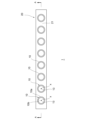
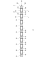
- FIG. 2 is a plan view of the gasket shown in FIG. 1 .
- 3 is a cross-sectional view of the gasket taken along line AA in FIG. 2.
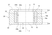
- 4 is an enlarged cross-sectional view showing the vicinity of a flow path of the gasket shown in FIG. 3 .
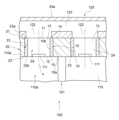
- FIG. 4 is a partial cross-sectional view of the battery module showing a cross section of the gasket in a used state attached to the battery module.
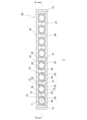
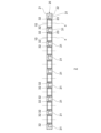
- FIG. FIG. 4 is a partially enlarged cross-sectional view showing a modified example of the gasket according to the first embodiment of the present invention.
- the gasket according to the present invention is used in a battery module having multiple battery cells, such as a lithium-ion battery module, and serves to seal gas released from an explosion-proof valve provided in each battery cell.
- the gasket 1 comprises a flow path portion 10, which is a cylindrical member having a plurality of pairs of openings 11, 12, and a base 20 having a pair of surfaces, a front surface 21 and a back surface 22, facing away from each other.
- the base 20 is elastic.
- the flow path portion 10 is held by the base 20 such that the openings 11, 12 are open from the front surface 21 and the back surface 22 of the base 20, respectively, to form a flow path for the object to be sealed.
- the hardness of the base 20 is lower than the hardness of the flow path portion 10.
- a number of battery cells 110 are arranged in a row and fixed by fixing devices (not shown). For example, insulating resin (not shown) is interposed between the battery cells 110.
- the battery cells 110 are connected together to form a battery cell group 101.
- the battery cells 110 are secondary batteries such as lithium ion batteries, and are rechargeable.
- Each battery cell 110 has an external shape that is, for example, longer in the width direction (X direction) than in the height direction (Z direction) and has a thin rectangular shape in the thickness direction (Y direction).
- the battery cells 110 are arranged in the Y direction.
- Each battery cell 110 has an explosion-proof valve 111 as described above, and also has a pair of electrodes 112.
- the explosion-proof valve 111 and the electrodes 112 are provided on the upper surface 110a of the battery cell 110.
- the pair of electrodes 112 are arranged at both ends in the width direction, one of which is a positive electrode and the other is a negative electrode.
- the explosion-proof valve 111 is arranged in the center in the width direction.
- gas may be generated inside due to charging and discharging during use or due to external factors, causing the internal pressure to increase.
- the explosion-proof valve 111 opens when the internal pressure of the battery cell 110 rises to a certain level, and the generated gas is released. This prevents the internal pressure in the battery cell 110 from rising to an unacceptable level.
- the gas discharge path 123 is open to the outside space from the exhaust port 121.
- the gas ejected from each explosion-proof valve 111 passes through the flow path 10 of the gasket 1 and is guided to the discharge pipe 120, passes through the corresponding opening and gas discharge path, and is discharged from the exhaust port 121 to the outside space.
- the gasket 1 has the same number of flow path sections 10 as the explosion-proof valves 111 of the multiple battery cells 110 in the battery cell group 101 of the battery module 100, and is aligned corresponding to each of the explosion-proof valves 111 of the multiple battery cells 110.
- the multiple flow path sections 10 are aligned in a row, for example, at equal or approximately equal intervals.
- the flow path section 10 has a cylindrical shape extending along the axis x, and defines a flow path 13, which is a space extending along the axis x, inside.
- the axis x extends parallel or approximately parallel to the height direction (Z direction) in the battery module 100.
- the flow path section 10 has, for example, a cylindrical or approximately cylindrical shape with the axis x as the central axis or approximately the central axis.
- the shape of the flow path section 10 is not limited to a cylindrical shape, and for example, the flow path 10 may be a polygonal tube, and the shape of the cross section of the flow path 10 perpendicular to the axis x is not limited to a circle, but may be an ellipse, other circular shape, polygonal shape, etc.
- the flow path section 10 has an upper end face 14 and a lower end face 15, which are a pair of end faces in the axis x direction, and the upper end face 14 defines the opening 11, and the lower end face 15 defines the opening 12.
- the upper end surface 14 and the lower end surface 15 each extend, for example, along a plane perpendicular to the axis x.
- the flow path 13 extends between the opening 11 and the opening 12.
- the openings 11 and 12 of the flow passage 10 each have a shape corresponding to the explosion-proof valve 111 of the battery cell 110, and for example, have a shape capable of accommodating the explosion-proof valve 111 therein.
- the diameters of the openings 11 and 12 are larger than the width in the width direction (X direction) and the width in the thickness direction (Y direction) of the explosion-proof valve 111, respectively.
- the gasket 1 can be attached to the battery module 100 regardless of the orientation of the axis x direction of the gasket 1, but only one of the openings 11 and 12 of the flow passage 10 may have a shape corresponding to the explosion-proof valve 111 of the battery cell 110 as described above.
- the side of the openings 11 and 12 of the flow passage 10 having a shape corresponding to the explosion-proof valve 111 is the battery cell group 101 side.
- the base 20 has a plate-like shape extending in the direction in which the multiple flow path sections 10 are arranged.
- the front surface 21 and back surface 22 of the base 20 extend parallel or approximately parallel to each other, as shown in Figure 3, for example, and are flat or approximately flat, extending along a plane perpendicular to the axis x.
- the front surface 21 and back surface 22 of the base 20 do not have to be flat.
- the front surface 21 and back surface 22 may be curved surfaces such as curved surfaces or wavy surfaces, or may be structural surfaces.
- a structural surface is a surface having a shape corresponding to a predetermined structure, for example, a surface having a shape corresponding to the shape of the upper surface 110a of the battery cell 110 or the shape of the discharge pipe 120.
- the width of the base 20 in the axial x direction is greater than the width of the flow path section 10 in the axial x direction
- the surface 21 of the base 20 is above the upper end surface 14 of the flow path section 10
- the back surface 22 of the base 20 is below the lower end surface 15 of the flow path section 10.
- the upper side is the side in the axial x direction that the surface 21 faces
- the lower side is the side in the axial x direction that the back surface 22 faces.
- the width in the axial x direction between the upper end surface 14 of the flow path section 10 and the surface 21 of the base 20 and the width in the axial x direction between the lower end surface 15 of the flow path section 10 and the back surface 22 of the base 20 are the same or approximately the same.
- the base 20 is formed with a flow hole surface 23 that defines a flow hole 24, which is a through hole that accommodates the flow section 10.
- the flow hole surface 23 is a cylindrical surface that corresponds to the outer peripheral surface 10a, which is the outer peripheral surface of the flow section 10, and extends along the axis x.
- the flow surface 23 extends between the front surface 21 and the back surface 22 of the base 20, and the flow hole 24 penetrates the base 20 between the front surface 21 and the back surface 22.
- the flow hole surface 23 is in contact with the outer peripheral surface 10a of the flow section 10, and thus the flow section 10 is held by the base 20.
- the flow section 10 is, for example, fitted to the flow hole surface 23 and held by the base 20.
- the flow section 10 is, for example, bonded to the flow hole surface 23 and held by the base 20.
- the holding form of the flow section 10 in the base 20 may be other forms.
- the surface 21 of the base 20 is above the upper end surface 14 of the flow passage 10
- the back surface 22 of the base 20 is below the lower end surface 15 of the flow passage 10. Therefore, as shown in FIG. 4, the flow hole surface 23 and the flow hole 24 are respectively formed with an upper flow hole surface 23a and an upper flow hole portion 24a, which are portions located above the upper end surface 14 of the flow passage 10, and a lower flow hole surface 23b and a lower flow hole portion 24b, which are portions located below the lower end surface 15 of the flow passage 10.
- the shape of the upper through hole surface 23a of the through hole surface 23 may be different from the part (contact surface 23c) of the through hole surface 23 that contacts the outer peripheral surface 10a of the flow passage 10, and similarly, the shape of the lower through hole surface 23b of the through hole surface 23 may be different from the contact surface 23c of the through hole surface 23.
- the shape of the upper through hole surface 23a and the shape of the downstream passage surface 23b may be the same, or may be different from each other. Also, as shown in FIG.
- the upper crushing allowance d1 which is the width of the upper through-hole surface 23a of the base 20 in the axial x direction
- the lower crushing allowance d2 which is the width of the lower through-hole surface 23b of the base 20 in the axial x direction
- the upper crushing allowance d1 and the lower crushing allowance d2 may be different from each other.
- the base 20 has an upper flow hole portion 24a and a lower flow hole portion 24b defined by the upper flow hole surface 23a and the lower flow hole surface 23b, respectively, as described above. Therefore, in the gasket 1, the opening 11 of the flow path portion 10 is open to the space outside the gasket 1 via the upper flow hole portion 24a of the base 20, and the opening 12 of the flow path portion 10 is open to the space outside the gasket 1 via the lower flow hole portion 24a of the base 20.
- the upper and lower flow holes 23a and 23b of the base 20 each have a shape corresponding to the explosion-proof valve 111 of the battery cell 110, and for example, have a shape capable of accommodating the explosion-proof valve 111 therein.
- the diameters of the upper and lower flow holes 23a and 23b are larger than the width in the width direction (X direction) and the width in the thickness direction (Y direction) of the explosion-proof valve 111, respectively.
- the gasket 1 can be attached to the battery module 100 regardless of the orientation of the axis x direction of the gasket 1, but only one of the upper and lower flow holes 23a and 23b of the base 20 may have a shape corresponding to the explosion-proof valve 111 of the battery cell 110 as described above.
- the side of the upper flow hole 23a or the lower flow hole 23b of the base 20 having a shape corresponding to the explosion-proof valve 111 is the battery cell group 101 side.
- the hardness of the base 20 is lower than that of the flow path portion 10.
- the base 20 is a low-hardness member.
- the base 20 has a hardness that allows it to maintain its shape in a natural state without receiving external force, even though it has a low hardness.
- the base 20 has a hardness that generates a reaction force when compressed.
- the base 20 has a hardness that generates a reaction force on the upper surfaces of the multiple battery cells 110 and the discharge pipe 12 when compressed between the upper surfaces of the multiple battery cells 110 of the battery cell group 101 and the discharge pipe 120 in the state in which the gasket 1 is in use.
- the base 20 has a hardness that allows it to deform under the pressure of the gas discharged from the sealed object, i.e., the explosion-proof valve 111.
- the base 20 is a low-hardness member, and has a hardness that allows it to maintain its shape in a natural state where it is not subjected to external forces, and has a hardness that allows it to be compressed to generate a reaction force when in use, and also has a hardness that allows it to deform under the pressure of the gas released from the explosion-proof valve 111.
- the form of the base 20 is not limited to those having such hardness.
- the hardness of the base 20 is such that it deforms in accordance with the shape of the object to which it is attached when the battery module 100 is assembled. Specifically, the hardness of the base 20 is low such that when the gasket 1 is attached to the upper surface 110a of the battery cells 110 of the battery cell group 101 and when the gasket 1 is attached to the discharge pipe 120 when the battery module 100 is assembled, the base 10 deforms in accordance with the shape of the upper surface 110a of the battery cells 110 and the base 10 deforms in accordance with the shape of the discharge pipe 120.
- the base 10 When the gasket 1 is attached to the upper surface 110a of the battery cells 110 of the battery cell group 101, the base 10 may be pressed against the upper surface 110a of the battery cells 110 or against the discharge pipe 120, for example, by the force of a worker or the force of an assembly machine.
- the deformation of the base 10 in response to the shape of the upper surface 110a of the plurality of battery cells 110 during the installation of the gasket 1 described above may not be such that the base 10 completely corresponds to the shape of the upper surface 110a of the plurality of battery cells 110.
- the deformation of the base 10 may be such that a part of the base 10 contacts a part of the upper surface 110a of the plurality of battery cells 110, or such that a part of the base 10 contacts a part of the upper surface 110a of the plurality of battery cells 110 in a manner that allows the base 10 to be engaged.
- the deformation of the base 10 in response to the shape of the discharge pipe 120 during the installation of the gasket 1 described above may not be such that the base 10 completely corresponds to the shape of the discharge pipe 120.
- the deformation of the base 10 may be such that a part of the base 10 contacts a part of the discharge pipe 120, or such that a part of the base 10 contacts a part of the discharge pipe 120 in a manner that allows the base 10 to be engaged.
- the base 20 is made of, for example, low-hardness urethane having the hardness described above.
- the material of the base 20 is not limited to urethane.
- the material of the base 20 may be other materials having elasticity, such as low-hardness rubber or other elastomers having the hardness described above.
- the compounding ratio of the compounding components of the material of the base 20 is adjusted so that the hardness of the base 20 becomes the desired low hardness as described above.
- the compounding ratio of the isocyanate component is adjusted so that the hardness of the base 20 becomes the desired hardness.
- the flow path portion 10 is heat resistant and made of a heat resistant material.
- the flow path portion 10 is heat resistant to the temperature of the gas discharged from the explosion-proof valve 111, which is the object to be sealed.
- the temperature of the gas discharged from the explosion-proof valve 111 may reach 400°C or higher, and the flow path portion 10 has a heat resistance of, for example, 400°C or higher.
- the material of the flow path portion 10 is, for example, PTFE (polytetrafluoroethylene).
- the material of the flow path portion 10 may be other materials having the above-mentioned heat resistance.
- the hardness of the flow path portion 10 is higher than the hardness of the base body 20, and for example, the hardness of the base body 20 is such that it does not deform even when it receives the pressure of the gas discharged from the explosion-proof valve 111.
- the base body 20 may also have adhesiveness.
- the adhesiveness of the base body 20 is, for example, adhesiveness capable of fixing the base body 20 against a force based on the weight of the gasket 1.
- the adhesiveness of the base body 20 is such that when the base body 20 is attached to the upper surface 110a of the plurality of battery cells 110 of the battery cell group 101 or when the base body 20 is attached to the discharge pipe 120 during assembly of the battery module 100, the adhesiveness of the base body 20 allows the base body 20 to attach to the upper surface 110a of the plurality of battery cells 110 or the discharge pipe 120, and the base body 20 does not separate from the battery cell group 101 or the discharge pipe 120 even if the attitude of the battery cell group 101 or the discharge pipe 120 is changed, such as by tilting the battery cell group 101 or the discharge pipe 120.
- the adhesiveness of the base 20 may be such that the base 20 does not separate from the battery cell group 101 or the discharge pipe 120 even when an external force that is not large enough to remove the base 20 is applied, such as when an unintentional worker or the like comes into contact with the base 20.
- the degree of adhesion of the base body 20 is adjusted, for example, depending on the degree of adhesion required. Specifically, for example, when the base body 20 is attached to the upper surface 110a of the battery cells 110 of the battery cell group 101 during assembly of the battery module 100, or when the base body 20 is attached to the discharge pipe 120, the degree of adhesion of the base body 20 is adjusted based on the size of the contact area of the base body 20 with the upper surface 110a of the battery cells 110 or the discharge pipe 120. For example, if the contact area of the base body 20 with the upper surface 110a of the battery cells 110 or the discharge pipe 120 is large, the degree of adhesion of the base body 20 may be low.
- the contact area of the base body 20 with the upper surface 110a of the battery cells 110 or the discharge pipe 20 is large, the adhesive area is large, so that even if the adhesiveness is low, the base body 20 can be prevented from separating from the battery cell group 101 or the discharge pipe 120.
- the contact area of the base 20 with the upper surface 110a of the battery cells 110 or the discharge pipe 120 is small, the adhesion area is small, so it is better for the degree of adhesion of the base 20 to be large.
- the degree of adhesion of the base 20 is adjusted to a size corresponding to the size of the contact area of the base 20 with the attachment object, for example, to a size proportional to the size of the contact area of the base 20 with the attachment object.
- the degree of adhesion of the base 20 is adjusted, for example, by adjusting the material of the base 20.
- the material of the base 20 is urethane
- the lower the hardness of the base 20 the greater the adhesion, and therefore the degree of adhesion of the base 20 is adjusted by adjusting the compounding ratio of the isocyanate component.
- Figure 5 is a partial cross-sectional view of the battery module 100 showing a cross-section of the gasket 1 in a used state attached to the battery module 100.
- the gasket 1 in the use state, is sandwiched between the battery cell group 101 and the discharge pipe 120 to seal the flow path between each explosion-proof valve 111 and the opening 122 of the corresponding discharge pipe 120. Specifically, the surface 21 of the base 20 of the gasket 1 contacts the surface 120a of the discharge pipe 120, and the back surface 22 of the base 20 of the gasket 1 contacts the upper surface 110a of each battery cell 110 of the battery cell group 101, and the gasket 1 is compressed between the upper surface 110a of each battery cell 110 and the discharge pipe 120.
- the explosion-proof valve 111 is surrounded by the lower hole surface 23b of each of the flow hole surfaces 23 of the base 20, and the opening 122 of the discharge pipe 120 is surrounded by the upper hole surface 23a of each of the flow hole surfaces 23 of the base 20.
- the surface 21 of the base 20 contacts the upper surface 110a around the explosion-proof valve 111 of each battery cell 110, and the back surface 22 of the base 20 contacts the surface 120a around each opening 122 of the discharge pipe 120. In this way, the base 20 of the gasket 1 allows the gas discharged from the explosion-proof valve 111 to flow into the discharge pipe 120 through the flow hole 24 without leaking.
- the base 20 in the use state, is compressed in the axial x direction, for example, shrinking by the width of the upper crushing allowance d1 and the lower crushing allowance d2 (see Figure 4).
- the upper end surface 14 and the lower end surface 15 of the flow section 10 are in contact with the surface 120a of the discharge pipe 120 and the upper surface 110a of the corresponding battery cell 110. Therefore, as shown in Figure 5, in the use state, all or almost all of the flow hole surface 23 of the base 20 of the gasket 1 is covered by the flow path section 10.
- the base 20 compressed in the axial x direction may shrink by a width smaller than the width of the upper crushing allowance d1 and the lower crushing allowance d2 (see Figure 4).
- each flow path section 10 surrounds the corresponding opening 122 of the discharge pipe 120, and the lower end surface 15 of each flow path section 10 surrounds the corresponding explosion-proof valve 111. Note that in the usage state, the upper end surface 14 of each flow path section 10 does not have to surround the corresponding opening 122 of the discharge pipe 120, and a part or all of the upper end surface 14 of each flow path section 10 may be within the corresponding opening 122 of the discharge pipe 120 when viewed in the axial x direction.
- the flow hole surface 23 that defines each of the flow holes 24 of the base 20 is covered by the heat-resistant flow path portion 10, and the high-temperature, high-pressure gas released from the explosion-proof valve 111 does not come into direct contact with the flow hole surface 23 that defines each of the flow holes 24 of the base 20. If the flow hole surface 23 that defines each of the flow holes 24 of the base 20 is not completely covered by the heat-resistant flow path portion 10, the flow hole surface 23 that defines each of the flow holes 24 of the base 20 may be slightly exposed to the high-temperature, high-pressure gas released from the explosion-proof valve 111.
- the base 20 has low hardness. Therefore, the base 20 can easily conform to the shape of the mounting surface of the battery cell group 101 with which the base 20 comes into contact, the upper surface 110a of the battery cell 110, and the surface 120a of the discharge pipe 120. Therefore, the base 20 is easy to attach to the mounting object to which the gasket 1 is attached, and the gasket 1 is easy to attach to the mounting object. In this way, the base 20 has high conformability to the object with which the base 20 comes into contact. Therefore, the gasket 1 can be easily assembled to the mounting object of the gasket 1.
- the base 20 also has adhesive properties. This allows the base 20 to adhere to the mounting surface of the battery cell group 101 with which the base 20 comes into contact, the upper surface 110a of the battery cell 110, and the surface 120a of the discharge pipe 120. This makes it easy to attach the base 20 to the mounting object to which the gasket 1 is attached, and the gasket 1 is easy to attach to the mounting object. This also makes it easy to assemble the gasket 1 to the mounting object.
- the base 20 has a low hardness
- the flow hole surface 23 of the base 20 is exposed to the high-pressure gas released from the explosion-proof valve 111, the flow hole surface 23 is deformed, and the base 20 is deformed.
- the sealing property of the gasket 1 is reduced.
- the flow hole surface 23 of the base 20 is covered by the flow path portion 10, which has a high hardness, and the high-pressure gas released from the explosion-proof valve 111 does not directly contact the flow hole surface 23 of the base 20.
- the flow hole surface 23 of the base 20 is protected from the high-pressure gas released from the explosion-proof valve 111 by the flow path portion 10, which has a higher hardness and a higher pressure resistance than the base 20, and deformation of the flow hole surface 23 due to the high-pressure gas released from the explosion-proof valve 111 is prevented, or deformation of the flow hole surface 23 is suppressed.
- the gasket 2 also functions in the same way as the gasket 1 described above. In this way, the gasket 2 according to the second embodiment of the present invention can improve conformability to the object it comes into contact with, and can have excellent heat resistance and pressure resistance.
Landscapes
- Chemical & Material Sciences (AREA)
- Chemical Kinetics & Catalysis (AREA)
- Electrochemistry (AREA)
- General Chemical & Material Sciences (AREA)
- Engineering & Computer Science (AREA)
- General Engineering & Computer Science (AREA)
- Mechanical Engineering (AREA)
- Gas Exhaust Devices For Batteries (AREA)
Abstract
Description
Claims (12)
- 2つの部材の間で密封対象物を密封するためのガスケットであって、
複数の、一対の開口を有する筒状の部材である流路部と、
互いに背向する一対の面を有する基体と、を備え、
前記基体は、弾性を有しており、
前記流路部は、密封対象物の流路を形成するように、前記一対の開口が夫々前記基体の前記一対の面から開放されるように、前記基体に保持されており、
前記基体の硬度は、前記流路部の硬度よりも低い、
ガスケット。 - 前記基体は、外力を受けない自然状態において、形状を維持可能な硬度を有する、
請求項1に記載のガスケット。 - 前記基体は、前記2つの部材の間で圧縮されて反力を生じる硬度を有する、
請求項2に記載のガスケット。 - 前記基体は、前記密封対象物の圧力を受けて変形する硬度を有する、
請求項1に記載のガスケット。 - 前記基体は、低硬度の材料から形成されており、
前記低硬度の材料は、ゴム、ウレタン、エラストマーを含む、
請求項1に記載のガスケット。 - 前記流路部は、耐熱性を有する材料で形成されている、
請求項1に記載のガスケット。 - 前記流路部の耐熱性は、前記密封対象物の温度に対する耐熱性である、
請求項6に記載のガスケット。 - 前記材料は、PTFEである、
請求項6に記載のガスケット。 - 前記基体は、粘着性を有している、
請求項1に記載のガスケット。 - 前記基体の粘着性は、前記ガスケットの自重に基づく力に対して前記基体を固定可能な粘着性である、
請求項9に記載のガスケット。 - 前記基体は、互いに隣接する2つの前記流路部の間に凹部を有しており、
前記凹部は、前記基体の一対の面の面する方向に凹んでいる、
請求項1に記載のガスケット。 - 前記2つの部材の一方は、バッテリモジュールの複数のバッテリセルであり、
前記2つの部材の他方は、前記複数のバッテリセルの各々の防爆弁から放出されたガスを案内する空間を形成するガス放出部であり、
前記密封対象物は、前記複数の防爆弁から放出されるガスであり、
前記複数の流路部は夫々、前記複数の防爆弁から放出されるガスの流路を形成する、
請求項1に記載のガスケット。
Priority Applications (4)
| Application Number | Priority Date | Filing Date | Title |
|---|---|---|---|
| CN202480036979.XA CN121241476A (zh) | 2023-06-09 | 2024-05-31 | 垫片 |
| KR1020257038143A KR20260005289A (ko) | 2023-06-09 | 2024-05-31 | 개스킷 |
| JP2025526092A JPWO2024253043A1 (ja) | 2023-06-09 | 2024-05-31 | |
| EP24819273.4A EP4726897A1 (en) | 2023-06-09 | 2024-05-31 | Gasket |
Applications Claiming Priority (2)
| Application Number | Priority Date | Filing Date | Title |
|---|---|---|---|
| JP2023095907 | 2023-06-09 | ||
| JP2023-095907 | 2023-06-09 |
Publications (1)
| Publication Number | Publication Date |
|---|---|
| WO2024253043A1 true WO2024253043A1 (ja) | 2024-12-12 |
Family
ID=93795938
Family Applications (1)
| Application Number | Title | Priority Date | Filing Date |
|---|---|---|---|
| PCT/JP2024/020072 Ceased WO2024253043A1 (ja) | 2023-06-09 | 2024-05-31 | ガスケット |
Country Status (5)
| Country | Link |
|---|---|
| EP (1) | EP4726897A1 (ja) |
| JP (1) | JPWO2024253043A1 (ja) |
| KR (1) | KR20260005289A (ja) |
| CN (1) | CN121241476A (ja) |
| WO (1) | WO2024253043A1 (ja) |
Citations (4)
| Publication number | Priority date | Publication date | Assignee | Title |
|---|---|---|---|---|
| JP2009019740A (ja) * | 2007-07-13 | 2009-01-29 | Nok Corp | 密封装置 |
| JP2010277736A (ja) * | 2009-05-26 | 2010-12-09 | Sanyo Electric Co Ltd | 電源装置及びこれを備える車両 |
| JP2013008673A (ja) * | 2011-06-23 | 2013-01-10 | Sb Limotive Co Ltd | バッテリモジュール |
| WO2017086469A1 (ja) * | 2015-11-20 | 2017-05-26 | Nok株式会社 | シリンダヘッドガスケット |
Family Cites Families (1)
| Publication number | Priority date | Publication date | Assignee | Title |
|---|---|---|---|---|
| WO2021026978A1 (zh) | 2019-08-09 | 2021-02-18 | 欣旺达电动汽车电池有限公司 | 电池模组 |
-
2024
- 2024-05-31 KR KR1020257038143A patent/KR20260005289A/ko active Pending
- 2024-05-31 WO PCT/JP2024/020072 patent/WO2024253043A1/ja not_active Ceased
- 2024-05-31 EP EP24819273.4A patent/EP4726897A1/en active Pending
- 2024-05-31 CN CN202480036979.XA patent/CN121241476A/zh active Pending
- 2024-05-31 JP JP2025526092A patent/JPWO2024253043A1/ja active Pending
Patent Citations (4)
| Publication number | Priority date | Publication date | Assignee | Title |
|---|---|---|---|---|
| JP2009019740A (ja) * | 2007-07-13 | 2009-01-29 | Nok Corp | 密封装置 |
| JP2010277736A (ja) * | 2009-05-26 | 2010-12-09 | Sanyo Electric Co Ltd | 電源装置及びこれを備える車両 |
| JP2013008673A (ja) * | 2011-06-23 | 2013-01-10 | Sb Limotive Co Ltd | バッテリモジュール |
| WO2017086469A1 (ja) * | 2015-11-20 | 2017-05-26 | Nok株式会社 | シリンダヘッドガスケット |
Also Published As
| Publication number | Publication date |
|---|---|
| KR20260005289A (ko) | 2026-01-09 |
| CN121241476A (zh) | 2025-12-30 |
| EP4726897A1 (en) | 2026-04-15 |
| JPWO2024253043A1 (ja) | 2024-12-12 |
Similar Documents
| Publication | Publication Date | Title |
|---|---|---|
| CN112335097B (zh) | 具有能够在发生热失控时防止空气流入模块的结构的电池模块和包括该电池模块的电池组 | |
| CN210956735U (zh) | 电池组 | |
| CN100561773C (zh) | 电池组 | |
| US6278259B1 (en) | Gas discharging device for battery pack | |
| CN101180750B (zh) | 叠层电池的安全机构 | |
| CN115803950B (zh) | 电池模块和包括该电池模块的电池组 | |
| ES2480272T3 (es) | Carcasa de compresión para una pila de células de combustible y método para la fabricación de una carcasa de compresión para una pila de células de combustible | |
| JPWO2019021980A1 (ja) | 電池モジュール | |
| KR20070093171A (ko) | 고율 충방전 원통형 이차전지 | |
| CN111587498B (zh) | 用于壳体的安全阀以及用于储存电能的储能器 | |
| JP5684053B2 (ja) | 密閉型電池及び安全弁 | |
| KR102566979B1 (ko) | 이차전지 및 그 이차전지를 포함하는 전지 팩 | |
| KR101080130B1 (ko) | 전해액 누출시 안전성이 보장된 전지팩 | |
| JP4337394B2 (ja) | 燃料電池 | |
| CN100448080C (zh) | 燃料电池用隔板和固体高分子型燃料电池 | |
| US3556863A (en) | Normally sealed encased rechargeable cells with self-resealing excess pressure gas vent | |
| CN121241476A (zh) | 垫片 | |
| WO2026034284A1 (ja) | ガスケット | |
| WO2026045087A1 (zh) | 防爆阀、电池装置、储能装置和用电装置 | |
| RU2449424C2 (ru) | Прокладка, биполярная батарея и способ изготовления прокладки | |
| EP4685946A1 (en) | Battery pack | |
| JP7431203B2 (ja) | 電池セル | |
| CN223728868U (zh) | 一种单体电池及电池包 | |
| US20260066441A1 (en) | Battery cell and battery module including the same | |
| JP2025173662A (ja) | 安全弁装置、安全弁ユニット、電池ユニットおよび安全弁装置の製造方法 |
Legal Events
| Date | Code | Title | Description |
|---|---|---|---|
| 121 | Ep: the epo has been informed by wipo that ep was designated in this application |
Ref document number: 24819273 Country of ref document: EP Kind code of ref document: A1 |
|
| WWE | Wipo information: entry into national phase |
Ref document number: KR1020257038143 Country of ref document: KR |
|
| ENP | Entry into the national phase |
Ref document number: 2025526092 Country of ref document: JP Kind code of ref document: A |
|
| WWE | Wipo information: entry into national phase |
Ref document number: CN202480036979X Country of ref document: CN |
|
| WWE | Wipo information: entry into national phase |
Ref document number: 2024819273 Country of ref document: EP |
|
| NENP | Non-entry into the national phase |
Ref country code: DE |
|
| ENP | Entry into the national phase |
Ref document number: 2024819273 Country of ref document: EP Effective date: 20260109 |
|
| ENP | Entry into the national phase |
Ref document number: 2024819273 Country of ref document: EP Effective date: 20260109 |
|
| ENP | Entry into the national phase |
Ref document number: 2024819273 Country of ref document: EP Effective date: 20260109 |
|
| ENP | Entry into the national phase |
Ref document number: 2024819273 Country of ref document: EP Effective date: 20260109 |
|
| ENP | Entry into the national phase |
Ref document number: 2024819273 Country of ref document: EP Effective date: 20260109 |
|
| WWP | Wipo information: published in national office |
Ref document number: 2024819273 Country of ref document: EP |