WO2024253021A1 - 車輪位置検出装置 - Google Patents
車輪位置検出装置 Download PDFInfo
- Publication number
- WO2024253021A1 WO2024253021A1 PCT/JP2024/019921 JP2024019921W WO2024253021A1 WO 2024253021 A1 WO2024253021 A1 WO 2024253021A1 JP 2024019921 W JP2024019921 W JP 2024019921W WO 2024253021 A1 WO2024253021 A1 WO 2024253021A1
- Authority
- WO
- WIPO (PCT)
- Prior art keywords
- side communication
- tire
- acceleration
- angle
- communication device
- Prior art date
- Legal status (The legal status is an assumption and is not a legal conclusion. Google has not performed a legal analysis and makes no representation as to the accuracy of the status listed.)
- Ceased
Links
Images





Classifications
-
- G—PHYSICS
- G01—MEASURING; TESTING
- G01S—RADIO DIRECTION-FINDING; RADIO NAVIGATION; DETERMINING DISTANCE OR VELOCITY BY USE OF RADIO WAVES; LOCATING OR PRESENCE-DETECTING BY USE OF THE REFLECTION OR RERADIATION OF RADIO WAVES; ANALOGOUS ARRANGEMENTS USING OTHER WAVES
- G01S13/00—Systems using the reflection or reradiation of radio waves, e.g. radar systems; Analogous systems using reflection or reradiation of waves whose nature or wavelength is irrelevant or unspecified
- G01S13/74—Systems using reradiation of radio waves, e.g. secondary radar systems; Analogous systems
- G01S13/76—Systems using reradiation of radio waves, e.g. secondary radar systems; Analogous systems wherein pulse-type signals are transmitted
- G01S13/765—Systems using reradiation of radio waves, e.g. secondary radar systems; Analogous systems wherein pulse-type signals are transmitted with exchange of information between interrogator and responder
-
- G—PHYSICS
- G01—MEASURING; TESTING
- G01L—MEASURING FORCE, STRESS, TORQUE, WORK, MECHANICAL POWER, MECHANICAL EFFICIENCY, OR FLUID PRESSURE
- G01L17/00—Devices or apparatus for measuring tyre pressure or the pressure in other inflated bodies
-
- B—PERFORMING OPERATIONS; TRANSPORTING
- B60—VEHICLES IN GENERAL
- B60C—VEHICLE TYRES; TYRE INFLATION; TYRE CHANGING; CONNECTING VALVES TO INFLATABLE ELASTIC BODIES IN GENERAL; DEVICES OR ARRANGEMENTS RELATED TO TYRES
- B60C23/00—Devices for measuring, signalling, controlling, or distributing tyre pressure or temperature, specially adapted for mounting on vehicles; Arrangement of tyre inflating devices on vehicles, e.g. of pumps or of tanks; Tyre cooling arrangements
- B60C23/02—Signalling devices actuated by tyre pressure
- B60C23/04—Signalling devices actuated by tyre pressure mounted on the wheel or tyre
-
- B—PERFORMING OPERATIONS; TRANSPORTING
- B60—VEHICLES IN GENERAL
- B60C—VEHICLE TYRES; TYRE INFLATION; TYRE CHANGING; CONNECTING VALVES TO INFLATABLE ELASTIC BODIES IN GENERAL; DEVICES OR ARRANGEMENTS RELATED TO TYRES
- B60C23/00—Devices for measuring, signalling, controlling, or distributing tyre pressure or temperature, specially adapted for mounting on vehicles; Arrangement of tyre inflating devices on vehicles, e.g. of pumps or of tanks; Tyre cooling arrangements
- B60C23/02—Signalling devices actuated by tyre pressure
- B60C23/04—Signalling devices actuated by tyre pressure mounted on the wheel or tyre
- B60C23/0408—Signalling devices actuated by tyre pressure mounted on the wheel or tyre transmitting the signals by non-mechanical means from the wheel or tyre to a vehicle body mounted receiver
- B60C23/0415—Automatically identifying wheel mounted units, e.g. after replacement or exchange of wheels
- B60C23/0416—Automatically identifying wheel mounted units, e.g. after replacement or exchange of wheels allocating a corresponding wheel position on vehicle, e.g. front/left or rear/right
-
- B—PERFORMING OPERATIONS; TRANSPORTING
- B60—VEHICLES IN GENERAL
- B60C—VEHICLE TYRES; TYRE INFLATION; TYRE CHANGING; CONNECTING VALVES TO INFLATABLE ELASTIC BODIES IN GENERAL; DEVICES OR ARRANGEMENTS RELATED TO TYRES
- B60C23/00—Devices for measuring, signalling, controlling, or distributing tyre pressure or temperature, specially adapted for mounting on vehicles; Arrangement of tyre inflating devices on vehicles, e.g. of pumps or of tanks; Tyre cooling arrangements
- B60C23/02—Signalling devices actuated by tyre pressure
- B60C23/04—Signalling devices actuated by tyre pressure mounted on the wheel or tyre
- B60C23/0408—Signalling devices actuated by tyre pressure mounted on the wheel or tyre transmitting the signals by non-mechanical means from the wheel or tyre to a vehicle body mounted receiver
- B60C23/0422—Signalling devices actuated by tyre pressure mounted on the wheel or tyre transmitting the signals by non-mechanical means from the wheel or tyre to a vehicle body mounted receiver characterised by the type of signal transmission means
- B60C23/0433—Radio signals
- B60C23/0447—Wheel or tyre mounted circuits
- B60C23/0455—Transmission control of wireless signals
- B60C23/0462—Structure of transmission protocol
-
- B—PERFORMING OPERATIONS; TRANSPORTING
- B60—VEHICLES IN GENERAL
- B60C—VEHICLE TYRES; TYRE INFLATION; TYRE CHANGING; CONNECTING VALVES TO INFLATABLE ELASTIC BODIES IN GENERAL; DEVICES OR ARRANGEMENTS RELATED TO TYRES
- B60C23/00—Devices for measuring, signalling, controlling, or distributing tyre pressure or temperature, specially adapted for mounting on vehicles; Arrangement of tyre inflating devices on vehicles, e.g. of pumps or of tanks; Tyre cooling arrangements
- B60C23/02—Signalling devices actuated by tyre pressure
- B60C23/04—Signalling devices actuated by tyre pressure mounted on the wheel or tyre
- B60C23/0486—Signalling devices actuated by tyre pressure mounted on the wheel or tyre comprising additional sensors in the wheel or tyre mounted monitoring device, e.g. movement sensors, microphones or earth magnetic field sensors
-
- B—PERFORMING OPERATIONS; TRANSPORTING
- B60—VEHICLES IN GENERAL
- B60C—VEHICLE TYRES; TYRE INFLATION; TYRE CHANGING; CONNECTING VALVES TO INFLATABLE ELASTIC BODIES IN GENERAL; DEVICES OR ARRANGEMENTS RELATED TO TYRES
- B60C23/00—Devices for measuring, signalling, controlling, or distributing tyre pressure or temperature, specially adapted for mounting on vehicles; Arrangement of tyre inflating devices on vehicles, e.g. of pumps or of tanks; Tyre cooling arrangements
- B60C23/02—Signalling devices actuated by tyre pressure
- B60C23/04—Signalling devices actuated by tyre pressure mounted on the wheel or tyre
- B60C23/0486—Signalling devices actuated by tyre pressure mounted on the wheel or tyre comprising additional sensors in the wheel or tyre mounted monitoring device, e.g. movement sensors, microphones or earth magnetic field sensors
- B60C23/0488—Movement sensor, e.g. for sensing angular speed, acceleration or centripetal force
-
- B—PERFORMING OPERATIONS; TRANSPORTING
- B60—VEHICLES IN GENERAL
- B60C—VEHICLE TYRES; TYRE INFLATION; TYRE CHANGING; CONNECTING VALVES TO INFLATABLE ELASTIC BODIES IN GENERAL; DEVICES OR ARRANGEMENTS RELATED TO TYRES
- B60C23/00—Devices for measuring, signalling, controlling, or distributing tyre pressure or temperature, specially adapted for mounting on vehicles; Arrangement of tyre inflating devices on vehicles, e.g. of pumps or of tanks; Tyre cooling arrangements
- B60C23/02—Signalling devices actuated by tyre pressure
- B60C23/04—Signalling devices actuated by tyre pressure mounted on the wheel or tyre
- B60C23/0486—Signalling devices actuated by tyre pressure mounted on the wheel or tyre comprising additional sensors in the wheel or tyre mounted monitoring device, e.g. movement sensors, microphones or earth magnetic field sensors
- B60C23/0489—Signalling devices actuated by tyre pressure mounted on the wheel or tyre comprising additional sensors in the wheel or tyre mounted monitoring device, e.g. movement sensors, microphones or earth magnetic field sensors for detecting the actual angular position of the monitoring device while the wheel is turning
-
- G—PHYSICS
- G01—MEASURING; TESTING
- G01P—MEASURING LINEAR OR ANGULAR SPEED, ACCELERATION, DECELERATION, OR SHOCK; INDICATING PRESENCE, ABSENCE, OR DIRECTION, OF MOVEMENT
- G01P15/00—Measuring acceleration; Measuring deceleration; Measuring shock, i.e. sudden change of acceleration
- G01P15/18—Measuring acceleration; Measuring deceleration; Measuring shock, i.e. sudden change of acceleration in two or more dimensions
-
- G—PHYSICS
- G07—CHECKING-DEVICES
- G07C—TIME OR ATTENDANCE REGISTERS; REGISTERING OR INDICATING THE WORKING OF MACHINES; GENERATING RANDOM NUMBERS; VOTING OR LOTTERY APPARATUS; ARRANGEMENTS, SYSTEMS OR APPARATUS FOR CHECKING NOT PROVIDED FOR ELSEWHERE
- G07C5/00—Registering or indicating the working of vehicles
- G07C5/02—Registering or indicating driving, working, idle, or waiting time only
- G07C5/04—Registering or indicating driving, working, idle, or waiting time only using counting means or digital clocks
Definitions
- This disclosure relates to a wheel position detection device that identifies and registers the wheel to which a tire-side communication device is attached based on data transmitted from the tire-side communication device attached to each wheel, and is suitable for application to a tire pressure monitoring system (hereinafter referred to as TPMS).
- TPMS tire pressure monitoring system
- Patent Document 1 discloses a technology for detecting wheel position in a direct-type TPMS using a detection signal from a wheel speed sensor.
- This TPMS detects when the wheel has reached a specified rotational position based on an acceleration detection signal from an acceleration sensor (hereinafter referred to as a G sensor) provided in a tire-side communication device on the wheel side, and also detects the rotational position of the wheel when a wireless signal is received from the tire-side communication device on the vehicle body side. The wheel position is then detected by monitoring changes in these relative angles.
- a G sensor acceleration sensor
- the wheel position is detected by monitoring changes in the relative angle between the wheel rotational position detected on the wheel side and the wheel rotational position detected on the vehicle body side based on the deviation of a specified number of data, and determining that the variation from the initial value exceeds an allowable value.
- An object of the present disclosure is to provide a wheel position detection device that is capable of detecting the wheel position more quickly and with higher accuracy.
- a wheel position detection device for a vehicle comprising: a tire-side communication device attached to each of a plurality of wheels having tires; and a vehicle-side communication device provided on a vehicle body side, the wheel position detection device comprising:
- Each tire-side communication device attached to each of the plurality of wheels includes: an acceleration sensor for detecting a circumferential acceleration and a radial acceleration of the wheel to which each tire-side communication device is attached; a first control unit that stores the detection results of the acceleration sensors and creates a frame that stores individual identification information assigned to each of the tire-side communication units; a first communication unit that performs two-way communication with the vehicle-side communication device, including the transmission of the frame;
- the vehicle-side communication device includes: a second communication unit that receives the frame and transmits an instruction signal to each of the tire-side communication devices; a second control unit that determines which of the plurality of wheels the tire-side communication device that has transmitted the frame is attached to, and
- the sensor angle of each tire-side communication device is calculated based on the circumferential acceleration and radial acceleration detected by the tire-side communication device.
- the accumulated angle and accumulated rotation count are then calculated from the sensor angle, and wheel position detection is performed based on the fact that the accumulated angle and accumulated rotation count are different values for each wheel depending on the wheel position.
- the second control unit or the first control unit provided in each of the tire-side communication devices calculates the sensor angle based on only one of the circumferential acceleration and the radial acceleration, using an angle at which the tire-side communication device is located with respect to a wheel center of the wheel to which the tire-side communication device is attached as a sensor angle, and calculates, based on the sensor angle, a cumulative angle obtained by accumulating changes in the sensor angle from the measurement start timing to the measurement end timing or a cumulative number of rotations that the tire-side communication device has rotated with respect to the wheel center, The second control unit identifies which of the plurality of wheels each of the tire-side communication devices is attached to, based on the accumulated angle in each of the tire-side communication devices or the magnitude of the accumulated angle.
- the accumulated angle and accumulated number of rotations can be calculated based on the acceleration of one axis detected by the acceleration sensor, and wheel position detection can be performed.
- This type of wheel position detection can be performed without using the detection signal of the wheel speed sensor, making it possible to perform wheel position detection more quickly and with high accuracy, without being dependent on errors in the detection signal of the wheel speed sensor.
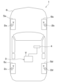
- FIG. 1 is a diagram showing a schematic configuration of a vehicle equipped with a TPMS having a wheel position detection function according to a first embodiment
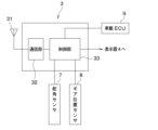
- FIG. 2 is a block diagram showing a tire-side communication device
- FIG. 2 is a block diagram showing a configuration of a vehicle-side communication device
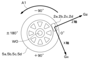
- 10 is a diagram showing the X-axis and Z-axis accelerations applied to the tire-side communication device as the wheel rotates, and the sensor angle, which is the angle at which the tire-side communication device is located with respect to the center of the wheel.
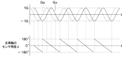
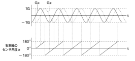
- FIG. 13 is a diagram showing time changes in acceleration along the X-axis and Z-axis and time changes in the sensor angle in a tire-side communication unit attached to a left wheel.
- FIG. 13 is a diagram showing time changes in acceleration along the X-axis and Z-axis and time changes in the sensor angle in a tire-side communication unit attached to a right wheel.
- FIG. 1 is a diagram showing the relationship between the state when a vehicle turns right and the turning radius of each wheel.
- FIG. 13 is a diagram showing the time change in acceleration of the X-axis of each of the four wheels and the time change in the sensor angle.
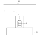
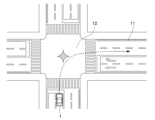
- FIG. FIG. 2 is a diagram showing a situation in which a vehicle capable of performing wheel position detection is turning; FIG.
- FIG. 2 is a diagram showing a situation in which a vehicle capable of performing wheel position detection is turning;
- 11 is a diagram showing an example of the time change in X-axis acceleration and sensor angle and the number of rotation periods in a tire-side communication unit attached to a left wheel.
- FIG. 13 is a diagram showing the X-axis and Z-axis accelerations applied to the tire-side communication unit as the right wheel rotates, and the sensor angle at which the tire-side communication unit is located with respect to the wheel center.
- FIG. 11 is a diagram showing an example of the time change in X-axis and Z-axis acceleration and sensor angle and the number of rotation periods in a tire-side communication unit attached to a left wheel.
- FIG. 11 is a diagram showing an example of the time change in X-axis and Z-axis acceleration and sensor angle and the number of rotation periods in a tire-side communication unit attached to a right wheel.
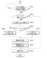
- FIG. 4 is a flowchart showing details of a wheel position detection process.
- 12B is a flowchart showing details of the wheel position detection process following FIG. 12A. 4 is a time chart when a wheel position detection process is executed.
- FIG. 11 is a waveform diagram of the sensor angle before correction.
- FIG. 11 is a waveform diagram of the sensor angle after correction.
- 11A and 11B are diagrams illustrating a change in acceleration on the X-axis and the corresponding pre-correction angle and post-correction angle.
- 10 is a flowchart showing details of a wheel position detection process according to a second embodiment. 16B is a flowchart showing details of the wheel position detection process following FIG. 16A.
- Fig. 1 is a block diagram showing the overall configuration of the TPMS, with the top of the page being the front of the vehicle 1, the bottom being the rear of the vehicle 1, and the left-right direction of the figure being the left-right direction of the vehicle 1.
- the TPMS is mounted on a vehicle 1 and is configured with tire-side communication devices 2a-2d, a vehicle-side communication device 3, and a display 4.
- the tire-side communication devices 2a-2d and the vehicle-side communication device 3 constitute the wheel position detection device.
- the tire-side communication devices 2a to 2d are attached to each of the four wheels 5a to 5d of the vehicle 1.
- the tire-side communication devices 2a to 2d detect the air pressure of the tires attached to each wheel 5a to 5d, and transmit the detection signal data indicating the detection result stored in a frame.
- the tire-side communication devices 2a to 2d are also capable of two-way communication with the vehicle-side communication device 3, and when they receive an instruction from the vehicle-side communication device 3, they enter wheel position detection mode and perform processing corresponding to the instruction, such as transmitting data required for wheel position detection (hereinafter referred to as position detection data).
- the vehicle-side communication device 3 is attached to the body 6 of the vehicle 1, and receives frames transmitted from the tire-side communication devices 2a-2d, and determines tire pressure by performing various processes and calculations based on the detection signal data stored therein.
- the vehicle-side communication device 3 issues instructions to each of the tire-side communication devices 2a-2d to have them transmit frames containing position detection data, and detects the wheel position based on that data.
- Figures 2A and 2B show the block configurations of the tire-side communication devices 2a-2d and the vehicle-side communication device 3.
- the tire-side communication devices 2a to 2d are configured with a sensing unit 21, a G sensor 22, a control unit 23, a communication unit 24, and an antenna 25.
- the sensing unit 21 is configured to include, for example, a pressure sensor and a temperature sensor, and outputs a detection signal corresponding to the tire air pressure and a detection signal corresponding to the temperature. For example, the sensing unit 21 outputs a detection signal corresponding to the tire air pressure and a detection signal corresponding to the temperature at each predetermined sampling period.
- the G sensor 22 detects the acceleration that accompanies the rotation of the wheels 5a to 5d to which the tire-side communication devices 2a to 2d are attached.
- the G sensor 22 detects biaxial acceleration. Specifically, if the circumferential direction of the wheels 5a to 5d is the X-axis direction and the radial direction is the Z-axis direction as shown in FIG. 3, the G sensor 22 detects biaxial acceleration in the X-axis direction and the Z-axis direction.
- acceleration Gx the acceleration in the X-axis direction
- acceleration Gz the acceleration in the Z-axis direction
- the G sensor 22 also outputs a detection signal corresponding to the acceleration at a sampling period that is the same as or different from the sampling period of the sensing unit 21. More specifically, the G sensor 22 outputs a detection signal corresponding to the acceleration, with the direction in which the wheels 5a to 5d rotate in one direction being the positive direction, and the direction in which they rotate in the opposite direction being the negative direction. If the direction in which the right wheels 5b, 5d rotate when the vehicle 1 moves forward is the positive direction, then the left wheels 5a, 5c will rotate in the opposite negative direction.
- the wheels 5a to 5d are the left wheels 5a and 5c, with the left side of the page being the front of the vehicle 1 and the right side being the rear of the vehicle 1.
- the left wheels 5a and 5c rotate counterclockwise as indicated by the arrow A1 in the figure, and the sensor angle ⁇ , which is the angle at which the tire-side communication devices 2a to 2d equipped with the G sensor 22 are positioned relative to the wheel center WO, changes.
- the sensor angle ⁇ can be expressed as 0° when the tire-side communication devices 2a to 2d are positioned at the rightmost position relative to the wheel center WO, -90° when they are positioned at the topmost position, ⁇ 180° when they are positioned at the leftmost position, and +90° when they are positioned at the topmost position.
- the rightmost position relative to the wheel center WO corresponds to the rearmost side of the vehicle 1
- the leftmost position corresponds to the frontmost side of the vehicle 1.
- the sensor angle ⁇ is indicated in the same way as for the left wheels 5a, 5c, but because the tire-side communication devices 2a-2d are attached to each wheel 5a-5d in the same direction, the correspondence with the front-to-rear direction of the vehicle 1 is reversed.
- the rightmost side of the wheel center WO corresponds to the frontmost side of the vehicle 1
- the leftmost side corresponds to the rearmost side of the vehicle 1.
- the right wheels 5b, 5d rotate clockwise, which is the opposite direction to the arrow A1 in Figure 3.
- the output corresponding to the acceleration Gx detected by the G sensor 22 has opposite positive and negative signs for the right wheels 5b, 5d and the left wheels 5a, 5c.
- the positive and negative signs may be the same for the right wheels 5b, 5d and the left wheels 5a, 5c.
- the control unit 23 corresponds to the first control unit, and is configured by a microcomputer equipped with a CPU, ROM, RAM, I/O, etc., and executes predetermined processing according to a program stored in the ROM, etc.
- control unit 23 receives a detection signal related to tire pressure from the sensing unit 21, processes the signal and manipulates it as necessary to create data indicating the tire pressure detection results (hereinafter referred to as tire pressure data).
- the control unit 23 then stores the tire pressure data in a frame to be transmitted together with the ID information of each tire-side communication device 2a-2d, and then transmits the frame to the communication unit 24.
- This process of transmitting a signal to the communication unit 24 is executed, for example, at a predetermined regular transmission interval, in accordance with the above program.
- the control unit 23 is basically in a periodic transmission mode in which it transmits a frame containing data on tire pressure together with ID information to the vehicle-side communication device 3 at a predetermined periodic transmission cycle.
- the control unit 23 receives an instruction to start acceleration measurement from the vehicle-side communication device 3 based on two-way communication, it enters a wheel position detection mode and starts measuring the acceleration Gx and acceleration Gz based on the detection signal of the G sensor 22 in order to detect the wheel position.
- the sampling cycle for the acceleration by the G sensor 22 is arbitrary, but is set to a cycle that allows multiple measurements of acceleration during one rotation of the wheels 5a to 5d, for example 10 ms.
- the control unit 23 performs a process of storing the measured acceleration data as position detection data in a frame together with the ID information of each wheel 5a to 5d and transmitting the data.
- control unit 23 when the control unit 23 receives an instruction from the vehicle-side communication device 3 based on two-way communication to end wheel position detection, it ends the measurement of acceleration and also ends the transmission of the frame containing the position detection data. Then, the control unit 23 switches from the wheel position detection mode to the periodic transmission mode and performs periodic transmission of a frame containing data related to tire pressure.
- the communication unit 24 corresponds to a first communication unit that performs two-way communication with the vehicle-side communication device 3 via the antenna 25. Specifically, the communication unit 24 functions as an output unit that transmits frames sent from the control unit 23 to the vehicle-side communication device 3 via the antenna 25, and as an input unit that receives instruction signals indicating instructions from the vehicle-side communication device 3.
- the communication format used by the communication unit 24 is arbitrary, but two-way communication between the tire-side communication devices 2a-2d and the vehicle-side communication device 3 is, for example, based on the BLE (Bluetooth Low Energy) standard. Note that "Bluetooth" is a registered trademark.
- the antenna 25 is a communication antenna that corresponds to the communication mode of the communication unit 24, and is built into the tire-side communication devices 2a to 2d, for example, and has the function of a transmitting and receiving antenna that can perform two-way communication.
- the transmitting and receiving antenna functions do not have to be realized by a single antenna, and may be separated into a transmitting antenna and a receiving antenna.
- the tire-side communication devices 2a-2d configured in this manner are attached, for example, to the air injection valves of the wheels of the wheels 5a-5d, and are positioned so that the sensing unit 21 is exposed to the inside of the tire.
- each tire-side communication device 2a-2d detects the tire pressure and transmits frames at predetermined regular transmission intervals via the antenna 25. Furthermore, when detecting the wheel position, each tire-side communication device 2a-2d transmits a frame that contains position detection data based on instructions from the vehicle-side communication device 3.
- the vehicle-side communication device 3 is configured with an antenna 31, a communication unit 32, and a control unit 33.
- the antenna 31 is a single common antenna that collectively receives frames sent from each of the tire-side communication devices 2a to 2d, and is fixed to the vehicle body 6.
- the antenna 31 may be one that is provided only for the TPMS, but if one that is provided for the smart entry system is used, it is possible to reduce the number of parts by standardizing the parts. "Smart Entry” is a registered trademark.
- the communication unit 32 corresponds to a second communication unit that performs two-way communication with each of the tire-side communication devices 2a-2d via the antenna 31. Specifically, when the communication unit 32 receives a frame transmitted from each of the tire-side communication devices 2a-2d via the antenna 31, it functions as an input unit that inputs the frame and sends it to the control unit 33. The communication unit 32 also functions as an output unit that transmits an instruction signal indicating an instruction sent from the control unit 33 to the vehicle-side communication device 3.
- the control unit 33 corresponds to a second control unit, and is configured by a microcomputer equipped with a CPU, ROM, RAM, I/O, etc., and executes predetermined processing according to a program stored in the ROM, etc.
- control unit 33 performs wheel position detection processing based on instructions from the vehicle-side communication device 3. That is, the control unit 33 receives frames storing position detection data from each of the tire-side communication devices 2a-2d via the communication unit 32. The control unit 33 then identifies which of the four wheels 5a-5d each of the tire-side communication devices 2a-2d is attached to, and registers the ID information assigned to each of the tire-side communication devices 2a-2d by linking it to the wheel position, that is, the wheel to which the tire-side communication device 2a-2d is attached.
- the control unit 33 executes the wheel position detection process, and when the wheel position detection start condition is met, it outputs an instruction signal to start acceleration measurement and executes the wheel position detection process.
- this wheel position detection process links and registers the wheel on which the tire side communication devices 2a-2d are attached with the ID information of each tire side communication device 2a-2d.
- the control unit 33 ends the wheel position detection process and outputs an instruction signal to each tire side communication device 2a-2d to instruct them to end acceleration measurement. This causes the control unit 23 of each tire side communication device 2a-2d to switch to a periodic transmission mode and begin to periodically transmit frames containing data related to tire pressure.
- the vehicle-side communication device 3 prefferably outputs an instruction signal to each of the tire-side communication devices 2a-2d to instruct them to end the acceleration measurement.
- the tire-side communication devices 2a-2d can automatically switch to a regular transmission cycle for frames for normal tire pressure detection.
- the control unit 33 is also configured to receive detection signals from the steering angle sensor 7 and gear position sensor 8, and these detection signals are used when performing wheel position detection processing. Furthermore, data related to vehicle speed is input to the control unit 33 from other on-board ECUs 9, such as a meter ECU. Of course, even if the detection signals from the steering angle sensor 7 and gear position sensor 8 are not directly input to the control unit 33, if another ECU detects the steering angle or gear position from these detection signals, the detection results may be transmitted from that ECU.
- control unit 33 performs various signal processing and calculations based on the data indicating the detection results stored in the received frame to determine the tire pressure, and outputs an electrical signal corresponding to the determined tire pressure to the display unit 4. For example, the control unit 33 identifies the tire pressure of each wheel 5a-5d and outputs the data to the display unit 4. Alternatively, the control unit 33 compares the determined tire pressure with a predetermined threshold value Th, and if it detects that the tire pressure has dropped, it outputs data to that effect to the display unit 4. This conveys to the display unit 4 the tire pressure data of the four wheels 5a-5d or that the tire pressure of any of the wheels 5a-5d has dropped.
- the display 4 is placed in a location visible to the driver, and is composed of, for example, a display and a warning lamp installed in the instrument panel of the vehicle 1.
- the display 4 displays the tire pressure of each wheel 5a-5d as a numerical value.
- the display 4 notifies the driver of the drop in tire pressure by displaying that fact.
- the TPMS to which the wheel position detection device of this embodiment is applied is configured as described above.
- wheel position detection is performed based on the accelerations Gx and Gz obtained from the detection signals of the G sensor 22 .
- the wheels 5a to 5d are the left wheels 5a and 5c, that the left side of the paper is the front of the vehicle 1, and the right side of the paper is the rear of the vehicle 1, and that the tire-side communication devices 2a and 2c are at a position where the sensor angle ⁇ is 0°, and that the vehicle 1 moves forward.
- the time changes of the acceleration Gx and the acceleration Gz are extracted by excluding the centrifugal acceleration component associated with the change in the running speed of the vehicle 1 and only the gravitational acceleration component, they are shown as a sine waveform that changes with time in accordance with the rotation of the wheels, as shown in the upper part of FIG. 4A.
- the acceleration Gx has a waveform that is delayed by a 1/4 cycle phase from the acceleration Gz.
- the time change of the sensor angle ⁇ of the tire-side communication devices 2a and 2c is a waveform that linearly transitions from 0° to -180° and linearly returns from 180° to 0°, as shown in the lower part of FIG. 4A. Therefore, the sensor angle ⁇ can be detected based on the waveforms of the acceleration Gx and the acceleration Gz.
- the changes over time in acceleration Gx and acceleration Gz are shown as sine waveforms that change with wheel rotation, as shown in the upper part of Figure 4B.
- the acceleration Gx has a waveform that is 1/4 cycle phase ahead of the acceleration Gz.
- the changes over time in the sensor angle ⁇ of the tire-side communication devices 2b, 2d are waveforms that move linearly from 0° to +180° and linearly return from -180° to 0°, as shown in the lower part of Figure 4B. For this reason, the sensor angle ⁇ can be detected based on the waveforms of the acceleration Gx and acceleration Gz.
- the turning radius of each wheel 5a to 5d will be different compared to the turning radius R of the vehicle center depending on the distance from the turning center to each wheel 5a to 5d. For example, consider the case where the vehicle 1 turns clockwise around point O as the turning center, as shown in Figure 5.
- the phase of the acceleration Gxc is slightly slower than the acceleration Gxa
- the phases of the accelerations Gxb and Gxd are even slower than the accelerations Gxa and Gxc
- the phase of the acceleration Gxd is slightly slower than the acceleration Gxb.
- the time changes of the sensor angles ⁇ a to ⁇ d of the tire-side communicators 2a to 2d also gradually differ among the wheels 5a to 5d.
- the magnitude of the accumulated angle obtained by accumulating the change in the sensor angle ⁇ of the tire-side communication devices 2a to 2d after the same amount of time has elapsed since the start of measurement using the inner wheel difference of each wheel 5a to 5d, or the magnitude of the accumulated number of rotations obtained by accumulating the number of rotations follows the order of the phase of the acceleration.
- the magnitude of the accumulated angle or the accumulated number of rotations will be left front wheel 5a > left rear wheel 5c > right front wheel 5b > right rear wheel 5d.
- the magnitude of the accumulated angle or the accumulated number of rotations will be right front wheel 5b > right rear wheel 5d > left front wheel 5a > left rear wheel 5c.
- wheel position detection is preferably performed when the vehicle 1 is turning under the conditions of a steering angle of a certain level or more and a vehicle speed of a certain level or more, that is, when it is confirmed that the vehicle 1 is actually turning. Therefore, when the wheel position detection process is executed, if the conditions of a steering angle of a certain level or more and a vehicle speed of a certain level or more are met, the vehicle-side communication device 3 may instruct each of the tire-side communication devices 2a to 2d to start measuring acceleration.
- the acceleration measurement may be terminated.
- the vehicle side communication device 3 may instruct each of the tire side communication devices 2a to 2d to terminate the acceleration measurement.
- the acceleration measurement may also be terminated when the data required for wheel position detection is collected during turning. Or, if the vehicle was turning but has stopped turning, the acceleration measurement may be terminated because data suitable for wheel position detection is no longer available.
- the vehicle side communication device 3 instructs each of the tire side communication devices 2a to 2d to terminate the acceleration measurement.
- the reason why the vehicle speed is maintained at or below a certain value for a certain period of time is set as the condition for the vehicle speed to be equal to or less than a certain value is that the vehicle may stop temporarily when turning right or left, and the acceleration measurement is not stopped until such a time.
- wheel position detection can be performed based on the accumulated angle or accumulated rotation count, but it is desirable that the acceleration data used in this case is for the same period, that is, that the measurement start and end timings are the same. For this reason, it is necessary to synchronize the measurement start and end timings of each tire-side communication device 2a to 2d. Possible methods for this include, for example, the following (1) and (2).
- each of the tire-side communication devices 2a-2d responds simultaneously accordingly. Then, each of the tire-side communication devices 2a-2d measures acceleration from the start of measurement until it receives a command to end measurement, and then each of the tire-side communication devices 2a-2d or the vehicle-side communication device 3 performs the processing required for wheel position detection.
- the vehicle-side communication device 3 broadcasts a measurement start command to each of the tire-side communication devices 2a-2d without synchronizing the clocks.
- Each tire-side communication device 2a-2d responds individually within a certain time after receiving the measurement start command, and measures acceleration until it receives a measurement start or measurement end command.
- each tire-side communication device 2a-2d or the vehicle-side communication device 3 performs the processing required for wheel position detection.
- method (1) can eliminate delays between the tire-side communication devices 2a-2d in data communication from the tire-side communication devices 2a-2d to the vehicle-side communication device 3, but requires a configuration for clock synchronization.
- method (2) does not require clock synchronization, so delays occur between the tire-side communication devices 2a-2d in data communication from the tire-side communication devices 2a-2d to the vehicle-side communication device 3, but the configuration can be simplified because no technology for clock synchronization is required.
- the method (2) is used to synchronize the measurement start timing and measurement end timing without synchronizing the clock, and the accumulated angle or accumulated number of rotations is calculated.
- the cumulative angle or cumulative number of rotations can also be calculated using the following two methods: (a) and (b).
- the acceleration Gx changes like a sine wave in association with the rotation of the wheel, as shown in the upper part of Figure 8.
- the sensor angle ⁇ in the case of the left wheels 5a and 5c, it repeatedly changes from 180° to -180° in response to the change in acceleration Gx, as shown in the lower part of Figure 8.
- the calculation of the cumulative angle ⁇ and cumulative rotation speed may be performed by the control unit 23 of each tire-side communication device 2a-2d, or the acceleration data or sensor angle ⁇ data may be transmitted from each tire-side communication device 2a-2d to the vehicle-side communication device 3 and may be performed by the control unit 33.
- the number of times it passes 180° in other words the number of rotational periods N based on the wheel rotation, can be calculated.
- the peaks of the acceleration Gx can be detected based on the acceleration Gx at sampling point Sp shown in the upper part of Figure 8.
- the acceleration Gx at sampling point Sp at any time t is taken as Gx(t), and Gx(t) is compared with the acceleration Gx from one cycle ago, Gx(t-1), and the sign of the difference Gx(t)-Gx(t-1) is calculated.
- the peaks of the acceleration Gx can be detected based on the fact that this sign becomes +, +, -, -.
- the number of rotational periods N can also be calculated by counting the number of times the condition is met, for example, where the acceleration goes from less than a certain acceleration to greater than or equal to a certain acceleration.
- the sensor angle ⁇ at each timing can be calculated using the acceleration Gz in addition to the acceleration Gx. This calculation method will be explained using the right wheels 5b and 5d as an example.
- the acceleration Gx is expressed as a component that forms a sensor angle ⁇ with respect to the gravitational acceleration component
- the acceleration Gz is expressed as a component that forms a sensor angle ⁇ with respect to the 0° position at the far right side of the wheel center WO, that is, the forwardmost position of the vehicle 1.
- HPF (Gz) means that high-pass filtering has been performed on the detection signal of the acceleration Gz.
- the sensor angle ⁇ is expressed as in Equation 1 and can be calculated using the two-axis acceleration Gx and acceleration Gz detected by the G sensor 22.
- the control unit 23 judges whether the sensor is attached to the left wheels 5a, 5c or the right wheels 5b, 5d (hereinafter referred to as left/right judgment), and then calculates the sensor angle ⁇ .
- the left/right judgment can be performed based on the phase shift amount of the sine waveforms of the acceleration Gx and acceleration Gz shown in the upper part of Figures 4A and 4B.
- the control unit 23 can judge that the sensor is attached to the left wheels 5a, 5c, and if it is 90° behind, the control unit 23 can judge that the sensor is attached to the right wheels 5b, 5d.
- the cumulative angle ⁇ is expressed as in Equation 2 using the number of rotation periods N, the sensor angle ⁇ s at the measurement start timing, and the sensor angle ⁇ e at the measurement end timing.
- (A°) mod 360° means that if A° is an angle exceeding 360°, an integer multiple of 360° is subtracted to make it an angle less than 360°.
- the accumulated angle ⁇ is expressed as in Equation 4 using the number of rotation periods N, the sensor angle ⁇ s at the measurement start timing, and the sensor angle ⁇ e at the measurement end timing.
- the accumulated angle ⁇ or accumulated rotation number of each tire-side communication device 2a to 2d can be calculated, and based on the magnitude of the calculated value and the vehicle 1, it can be determined to which of the wheels 5a to 5d each tire-side communication device 2a to 2d is attached, thereby enabling wheel position detection.
- FIGS. 12A and 12B are flow charts showing details of the wheel position detection process based on the above-described wheel position detection method.
- This wheel position detection process is executed by the control unit 33 at predetermined intervals, for example, when the user presses a wheel position detection start switch (not shown) during tire replacement. Details of the wheel position detection process will be explained with reference to the time charts shown in FIGS. 12A and 12B and 13 when the wheel position detection process is executed.
- step S100 in FIG. 12A the control unit 33 judges whether the vehicle 1 is turning or not.
- the conditions for this judgment may be set arbitrarily, but here, if the conditions of a steering angle of a certain level or more and a vehicle speed of a certain level or more are met, it is judged that the vehicle 1 is turning.
- a steering angle threshold is set as shown in FIG. 13, and a steering angle equal to or greater than this steering angle threshold is judged to be equal to or greater than a certain level.
- a speed threshold is set as shown in FIG. 13, and a vehicle speed equal to or greater than this speed threshold is judged to be equal to or greater than a certain level.
- step S100 This judgment is made based on the detection signal from the steering angle sensor 7 and data related to vehicle speed transmitted from another ECU. If a positive judgment is made here, the process proceeds to step S105, and if a negative judgment is made, the process of step S100 is repeated.
- step S105 the timer t for measuring time in the control unit 23 is reset. Then, the process proceeds to step S110, where, as shown at time T1 in FIG. 13, the vehicle-side communication device 3 transmits an instruction signal to each of the tire-side communication devices 2a to 2d to start acceleration measurement.
- the control unit 23 of each of the tire-side communication devices 2a to 2d switches from the periodic transmission mode to the wheel position detection mode. Then, the control unit 23 starts measuring the acceleration Gx and acceleration Gz and counting the number of rotation periods N from the timing of receiving the instruction, and returns a response signal to the vehicle-side communication device 3 in response to receiving the instruction to start measurement, and enters a reception standby state.
- BLE communication even if each of the tire-side communication devices 2a to 2d is not in a reception standby state called a scan, communication is possible based on the advertisement signal, so that the measurement start instruction can be transmitted to each of the tire-side communication devices 2a to 2d.
- step S115 it is determined whether the timer t has reached a predetermined time Ta or more.
- the predetermined time Ta here is a time set to be greater than or equal to the maximum delay time assumed between the issuance of an instruction to start measurement and the tire-side communication devices 2a to 2d starting acceleration measurement and returning a response signal, as shown in FIG. 13. If the timer t has reached the predetermined time Ta or more, it is assumed that a response signal has been returned from all tire-side communication devices 2a to 2d, even if there is a delay in the return of the response signal. The process of this step is repeated until a positive determination is made in step S115, and if a positive determination is made in step S115, the process proceeds to step S120.
- a response signal is returned from each tire-side communication device 2a to 2d, but it is also possible to simply determine that the predetermined time Ta is greater than or equal to the time when each tire-side communication device 2a to 2d is assumed to start acceleration measurement in response to an instruction, and the return of a response signal is optional.
- step S120 the same process as in step S100 is performed again to determine whether the conditions suitable for wheel position detection still exist. If the determination is affirmative here, the process proceeds to step S125, and if the determination is negative, the process returns to step S100.
- step S125 the control unit 33 informs each tire-side communication device 2a-2d that it is the measurement start timing Ts. Specifically, the control unit 33 transmits an instruction signal to each tire-side communication device 2a-2d to perform various processes to be executed at the measurement start timing Ts, instructing the device to acquire the start period number Ns, the start acceleration Gxs, and the start acceleration Gzs, which are the rotation period number N at the start and the acceleration Gx and acceleration Gz.
- control unit 23 of each tire-side communication device 2a-2d converts the start period number Ns, the start acceleration Gxs, and the start acceleration Gzs calculated, for example, by the method (b) described above, into digital form and returns the digital data to the vehicle-side communication device 3, where it is received by the vehicle-side communication device 3.
- the control unit 33 calculates the sensor angle ⁇ s at the measurement start timing Ts based on the start acceleration Gxs and start acceleration Gzs of the data received in step S125, using the above-mentioned formula 1. This process is performed for each received data, that is, for each tire-side communication device 2a-2d, and the sensor angle ⁇ s is calculated for each tire-side communication device 2a-2d. Then, proceeding to step S135, it is determined whether the vehicle 1 has finished turning. This determination condition can be set arbitrarily, but here it is determined that the vehicle 1 has finished turning if the condition that a steering angle or vehicle speed below a certain level is maintained for a certain period of time or more is met. This determination is also made based on the detection signal of the steering angle sensor 7 and data related to the vehicle speed transmitted from another ECU.
- the constant steering angle and constant vehicle speed here may be the same values as in steps S100 and S120, or may be values that are a predetermined amount smaller than those in steps S100 and S120, including a margin. If the conditions in step S135 are met, it is assumed that the situation will be one in which turning will end. After this, the inner wheel difference decreases and data suitable for wheel position detection cannot be obtained, so the data obtained up to this point will be used for wheel position detection. If the answer here is positive, the process proceeds to step S140 in FIG. 12B, and if the answer is negative, the process in step S135 is repeated.
- step S140 it is determined whether a predetermined time Tb or more has elapsed since the timer t reached the predetermined time Ta, in other words, whether the time elapsed since the measurement start timing Ts has reached the predetermined time Tb or more.
- the predetermined time Tb here is set as the minimum time from the measurement start timing Ts to the measurement end timing Te, as shown in FIG. 13, and is set arbitrarily based on the assumption that it is the time required to collect enough acceleration data to enable accurate wheel position detection. As shown in FIG. 8 above, the period Tcal from the measurement start timing Ts to the measurement end timing Te is set to a period equal to or greater than this predetermined time Tb. If a positive determination is made here, the process proceeds to step S145, and if a negative determination is made, the process proceeds to step S175.
- steps S135 and S140 are not essential, and only one of them may be performed. For example, only step S140 may be performed, and once a predetermined time Tb has elapsed from the predetermined time Ta, the data required for accurate wheel position detection is deemed to be available, and the process may proceed to step S145 and subsequent steps. Furthermore, wheel position detection may be performed using the data available until the condition of step S135 is met.
- step S145 the control unit 33 informs each tire-side communication device 2a-2d that it is the measurement end timing Te. Specifically, the control unit 33 transmits an instruction signal to each tire-side communication device 2a-2d to perform various processes to be executed at the measurement end timing Te, instructing the device to acquire the end period number Ne, which is the rotation period number N, acceleration Gx, and acceleration Gz at the time of completion, and the end acceleration Gxe and end acceleration Gze.
- control unit 23 of each tire-side communication device 2a-2d converts the end period number Ne, end acceleration Gxe, and end acceleration Gze calculated, for example, by the method (b) described above, into digital form and returns the digital data to the vehicle-side communication device 3, where it is received by the vehicle-side communication device 3.
- step S150 the control unit 33 calculates the sensor angle ⁇ e at the measurement end timing Te based on the end acceleration Gxe and end acceleration Gze from the data received in step S145, based on the above-mentioned formula 1.
- step S155 the left and right wheels 5a, 5c are determined as the left and right wheels.
- the left and right wheels 5a, 5c may be determined as the left and right wheels 5a, 5c as the left and right wheels 5b, 5d.
- the control unit 23 detects whether the vehicle 1 is traveling forward or backward from the detection signal of the gear position sensor 8, and determines which of the phases of the acceleration Gx and the acceleration Gz is advanced for the left wheels 5a, 5c and the right wheels 5b, 5d according to the detection result. For example, as shown in FIG. 13, when the vehicle 1 is traveling forward, if the phase of the acceleration Gz is advanced by 90° with respect to the acceleration Gx, it can be determined that the left wheels 5a, 5c are the wheels to which the control unit 23 is attached. Also, if there is a delay of 90 degrees, it can be determined that it is attached to the right wheel 5b, 5d.
- each of the tire-side communication devices 2a-2d can perform left/right determination based on the phase difference between the acceleration Gx and the acceleration Gz, and the data of the determination result is returned from each of the tire-side communication devices 2a-2d when the instruction in step S145 is given.
- step S160 If the answer is yes, proceed to step S160; if the answer is no, proceed to step S165.
- step S160 since the wheels are the left wheels 5a and 5c, the accumulated angle ⁇ for the left wheels 5a and 5c is calculated.
- the accumulated angle ⁇ can be calculated using the above-mentioned formula 2, and the number of rotation periods N in formula 2 is calculated as the difference between the end number of periods Ne obtained in step S145 and the start number of periods Ns obtained in step S125.
- step S165 since the wheels are right wheels 5b and 5d, the accumulated angle ⁇ for the right wheels 5b and 5d is calculated.
- the accumulated angle ⁇ can be calculated using the above-mentioned formula 4, and the number of rotation periods N in formula 4 is calculated as the difference between the end number of periods Ne obtained in step S145 and the start number of periods Ns obtained in step S125.
- step S170 and detect the wheel positions based on the accumulated angle ⁇ for the four wheels and the steering angle information, i.e., the turning direction of the vehicle 1 indicated by the detection signal of the steering angle sensor 7.
- the magnitude of the accumulated angle ⁇ is in the following relationship: left front wheel 5a > left rear wheel 5c > right front wheel 5b > right rear wheel 5d.
- the magnitude of the accumulated angle ⁇ is in the following relationship: right front wheel 5b > right rear wheel 5d > left front wheel 5a > left rear wheel 5c.
- step S175 where, as shown at time T2 in FIG. 13, the vehicle-side communication device 3 sends an instruction to each of the tire-side communication devices 2a-2d to end measurement, thereby ending the wheel position detection process. Then, upon receiving this instruction, each of the tire-side communication devices 2a-2d ends the acceleration measurement and cancels the reception standby state.
- wheel position can also be detected in the same way using the cumulative number of rotations, which is a value proportional to the cumulative angle ⁇ .
- each tire-side communication device 2a-2d switches from the wheel position detection mode to the periodic transmission mode. Then, each tire-side communication device 2a-2d begins to transmit a frame that stores data on tire pressure along with ID information to the vehicle-side communication device 3 at a predetermined periodic transmission cycle. When this is transmitted to the control unit 33 via the antenna 31, the control unit 33 performs various signal processing and calculations to determine the tire pressure, and identifies which of the wheels 5a-5d the tire pressure belongs to from the ID information stored in the frame. The control unit 33 then outputs an electrical signal corresponding to the determined tire pressure to the display 4. This makes it possible to inform the user of the tire condition by displaying the tire pressure on the display 4 in a form that identifies which of the wheels 5a-5d it belongs to, or by displaying a drop in tire pressure.
- the sensor angle ⁇ of each tire-side communication device 2a-2d is calculated based on the acceleration Gx and acceleration Gz detected by the tire-side communication devices 2a-2d.
- the accumulated angle ⁇ and accumulated rotation speed are then calculated from the sensor angle ⁇ , and wheel position detection is performed based on the fact that the accumulated angle ⁇ and accumulated rotation speed are different values for each wheel 5a-5d depending on the wheel position.
- the wheel position detection is performed based on the acceleration of one axis, unlike the first embodiment, and other points are the same as those in the first embodiment, so only the points different from the first embodiment will be described.
- acceleration Gx When acceleration Gx is used, as shown in FIG. 9, acceleration Gx is expressed as a component that forms a sensor angle ⁇ with respect to the component of gravitational acceleration. Therefore, the absolute value of the sensor angle ⁇ can be calculated as shown in Equation 6.
- sgn means a sign function
- dGx/dt is the time derivative of acceleration Gx, that is, the amount of change in acceleration Gx per unit time, and may be the amount of change in acceleration Gx between adjacent sampling points.
- the acceleration Gz is expressed as a component that forms a sensor angle ⁇ with respect to the position of 0° on the rightmost side of the wheel center WO, that is, the position of the right wheels 5b and 5d on the frontmost side of the vehicle 1. Therefore, the absolute value of the sensor angle ⁇ can be calculated as shown in Equation 7.
- the absolute value of the sensor angle ⁇ is calculated. Therefore, as shown in FIG. 14A, the sensor angle ⁇ is composed of a broken line portion that gradually increases with time, that is, a portion where the unit time change of the sensor angle ⁇ is ⁇ >0, and a solid line portion that gradually decreases with time, that is, a portion where the unit time change of the sensor angle ⁇ is ⁇ 0. If a minus sign is added to the broken line portion where the absolute value of the sensor angle ⁇ gradually increases with time, the sensor angle ⁇ will have a waveform in which the angle gradually decreases with time, as shown in FIG. 14B.
- the actual sensor angle ⁇ can be obtained by calculating a post-correction angle where a minus sign is added to the portion of the pre-correction angle where the absolute value of the sensor angle ⁇ gradually increases with time.
- the actual sensor angle ⁇ can be obtained based on the one-axis acceleration detected by the G sensor 22.
- a negative sign is added to the pre-correction angle to obtain the post-correction angle
- a negative sign may also be added to the pre-correction angle to obtain the post-correction angle.
- a correction is performed to add a negative sign to the pre-correction angle only in either the case where the pre-correction angle gradually increases or decreases with time, to obtain the post-correction angle, which can be used as the actual sensor angle ⁇ .
- the acceleration Gx on the X-axis has a sine waveform. Therefore, it is possible to determine whether or not to add a minus sign based on the relationship between the acceleration Gx(t) at sampling point Sp1 and the accelerations Gx(t-1) and Gx(t+1) at sampling points Sp0 and Sp2 in the sampling periods before and after that.
- State 1 shows the relationship Gx(t-1) ⁇ Gx(t) ⁇ Gx(t+1), in other words, the state where the acceleration Gx gradually increases.
- the pre-correction angle is in the process of gradually decreasing with time. Therefore, there is no need to correct the pre-correction angle by adding a minus sign, so the pre-correction angle is treated as the post-correction angle as is.
- the correction coefficient is set to 1, and the sensor angle ⁇ x 1 is set to the post-correction angle.
- State 2 shows the relationship Gx(t-1) ⁇ Gx(t), Gx(t+1), in other words, the state where acceleration Gx reaches its peak between sampling points Sp1 and Sp2. Even in this state, at sampling point Sp1, the pre-correction angle is still in the process of gradually decreasing with time. Therefore, there is no need to make a correction to the pre-correction angle by adding a minus sign, so like state 1, the pre-correction angle is treated as it is as the post-correction angle.
- State 3 shows the relationship Gx(t-1) ⁇ Gx(t+1) ⁇ Gx(t), in other words, the state where acceleration Gx reaches its peak around sampling point Sp1.
- the pre-correction angle is about to switch from decreasing to increasing with time, but it is not necessary to add a minus sign to the pre-correction angle yet. Therefore, just like state 1, the pre-correction angle is treated as the post-correction angle as is.
- State 4 shows the relationship Gx(t+1) ⁇ Gx(t-1) ⁇ Gx(t+1), in other words, the state where acceleration Gx reaches its peak between sampling points Sp0 and Sp1.
- the pre-correction angle has switched from descending to ascending with time, so a correction must be made to the pre-correction angle by adding a minus sign. Therefore, the corrected angle is calculated by adding a minus sign to the pre-correction angle.
- the correction coefficient is set to -1, and the sensor angle ⁇ x (-1) is set to the corrected angle.
- State 5 shows the relationship Gx(t+1) ⁇ Gx(t) ⁇ Gx(t-1), that is, the state where the acceleration Gx gradually decreases.
- the pre-correction angle is in the middle of gradually increasing with time, so a correction must be made to the pre-correction angle by adding a minus sign. Therefore, as in state 4, the post-correction angle is calculated by adding a minus sign to the pre-correction angle.
- the actual sensor angle ⁇ can be calculated based on the one-axis acceleration detected by the G sensor 22. Once the actual sensor angle ⁇ is obtained, it becomes possible to detect the wheel position based on this angle, in the same way as in the first embodiment.
- FIGS. 16A and 16B are flow charts showing details of the wheel position detection process of this embodiment. This wheel position detection process is executed by the control unit 33 at predetermined intervals, for example, when the user presses a wheel position detection start switch (not shown) during tire replacement, etc.
- steps S200 to S220 in FIG. 16A the same processing as in steps S100 to S120 in FIG. 12 in the first embodiment is performed.
- the control unit 33 transmits an instruction signal to each tire-side communication device 2a to 2d to instruct it to acquire the start period number Ns and the start acceleration Gxs for three sampling periods.
- the signal transmission timing is set to the measurement start timing Ts, and the start acceleration Gxs(t) at the measurement start timing Ts and the start accelerations Gxs(t-1) to Gxs(t+1) for three periods including the start acceleration Gxs(t) and the start accelerations before and after that are set.
- control unit 23 of each tire-side communication device 2a to 2d converts the start period number Ns and the start acceleration Gxs calculated, for example, by the method (b) described above, into digital form and returns it to the vehicle-side communication device 3, where it is received by the vehicle-side communication device 3.
- step S230 compare the starting accelerations Gxs(t-1) and Gxs(t+1) in the sampling periods before and after the measurement start timing Ts, and determine whether the relationship Gxs(t-1) ⁇ Gxs(t+1) is satisfied.
- step S235 the sensor angle ⁇ s at the measurement start timing Ts is calculated based on Equation 8 since there is no need to add a minus sign to the pre-correction angle.
- step S240 the sensor angle ⁇ s at the measurement start timing Ts is calculated based on Equation 9 since it is necessary to add a minus sign to the pre-correction angle.
- steps S230 to S240 is performed for each received data, i.e., for each tire-side communication device 2a to 2d.
- steps S245 and S250 the same processing as in steps S135 and S140 in FIG. 12 in the first embodiment is performed. If the determination in step S250 is affirmative, the process proceeds to step S255, and if the determination is negative, the process proceeds to step S285.
- step S255 the control unit 33 transmits an instruction signal to each of the tire-side communication devices 2a-2d to instruct them to obtain the end cycle number Ne and the end acceleration Gxe for three sampling cycles.
- the end acceleration Gxe for three sampling cycles refers to the end acceleration Gxe(t) at the measurement end timing Te, which is the measurement end timing Te, and the end accelerations Gxe(t-1) to Gxe(t+1) for three cycles including those before and after the measurement end timing Te.
- control unit 23 of each of the tire-side communication devices 2a-2d converts the end cycle number Ne and end acceleration Gxe calculated, for example, by the method (b) described above, into digital form and sends it back to the vehicle-side communication device 3, where it is received by the vehicle-side communication device 3.
- step S260 compare the end accelerations Gxe(t-1) and Gxe(t+1) in the sampling periods before and after the measurement end timing Te, and determine whether the relationship Gxe(t-1) ⁇ Gxe(t+1) is satisfied.
- step S265 the sensor angle ⁇ e at the measurement end timing Te is calculated based on Equation 10 since there is no need to add a minus sign to the pre-correction angle.
- step S270 in which the sensor angle ⁇ e at the measurement end timing Te is calculated based on Equation 11 since it is necessary to add a minus sign to the pre-correction angle.
- steps S255 to S270 is also performed for each piece of received data, i.e., for each tire-side communication device 2a to 2d.
- step S275 proceed to step S275 to calculate the cumulative angle ⁇ .
- the cumulative angle ⁇ can be calculated using Equation 2 for both the left wheels 5a, 5c and the right wheels 5b, 5d.
- step S280 where, similar to step S170 in FIG. 12 in the first embodiment, wheel position detection is performed based on the accumulated angle ⁇ for the four wheels and steering angle information, i.e., the turning direction of the vehicle 1 indicated by the detection signal of the steering angle sensor 7. Then, once it has been determined which of the four wheels 5a to 5d each of the four tire-side communication devices 2a to 2d is attached to, the ID information stored in the frame of each tire-side communication device 2a to 2d is linked to the wheel position and registered. Finally, the process proceeds to step S285, where an instruction to end measurement is sent from the vehicle-side communication device 3 to each tire-side communication device 2a to 2d, ending the wheel position detection process.
- wheel position detection can also be performed in the same way using the cumulative number of rotations, which is a value proportional to the cumulative angle ⁇ .
- tire air pressure detection is performed while identifying which of the wheels 5a to 5d each tire-side communication device 2a to 2d is attached to based on the results of wheel position detection.
- the cumulative angle ⁇ and the cumulative number of rotations can be calculated based on the acceleration of one axis detected by the G sensor 22, and wheel position detection can be performed. This makes it possible to obtain the same effect as the first embodiment.
- wheel position detection is performed based on one-axis acceleration as in this embodiment, there is no need to perform left/right determination, and when acceleration Gx is used, there is no need to perform high-pass filter processing as in the case of using acceleration Gz, making it possible to simplify the system.
- acceleration Gx when wheel position detection is performed using two-axis acceleration Gx and acceleration Gz as in the first embodiment, a larger amount of acceleration data is used, so the sensor angle ⁇ can be calculated with greater accuracy, making it possible to perform more accurate wheel position detection.
- the wheel position is detected using the cumulative angle ⁇ , but the wheel position may be detected using the cumulative number of rotations.
- an example of inputting an instruction to start wheel position detection is when a user presses a wheel position detection start switch (not shown) when changing tires, but a start instruction may be input in other ways.
- wheel position detection may be performed when an automobile repair shop inputs an instruction to start wheel position detection using a tool.
- wheel position detection may be performed when a start switch such as an ignition switch is pressed if the vehicle 1 has not been started for a predetermined time or longer.
- each tire-side communication device 2a to 2d acquires the rotation period number N and acceleration Gx, transmits the data to the vehicle-side communication device 3, and the vehicle-side communication device 3 calculates the sensor angle ⁇ .
- each tire-side communication device 2a to 2d may also calculate the sensor angle ⁇ and transmit the data on the rotation period number N and the sensor angle ⁇ to the vehicle-side communication device 3.
- the acceleration Gx at the sampling points Sp before and after that timing were used.
- the acceleration Gx at the three sampling points Sp two before and one before that timing, Gx(t-2), Gx(t-1), and G(t), which are the acceleration Gx at the three sampling points Sp one after and one after that timing, Gx(t), Gx(t+1), and G(t+2), which are the acceleration Gx at the three sampling points Sp one after and one after that timing may also be used.
- the sensor angle ⁇ may be calculated using the acceleration Gx at two or four or more sampling points Sp1, not limited to three sampling points Sp.
- a wheel position detection device is described that is provided for a vehicle 1 that has four wheels 5a to 5d, but the present disclosure can also be applied to vehicles that have a larger number of wheels.
- the accumulated angle ⁇ and accumulated rotation count are largest for the front wheel that is the outer wheel of the turn, and smallest for the rear wheel that is the inner wheel of the turn. In this way, the order of the magnitude of the accumulated angle ⁇ and accumulated rotation count is determined according to the wheel position, so wheel position detection can be performed based on that order.
- one of the conditions for starting acceleration measurement is when a steering angle of a certain value or more occurs.
- the steering angle is expressed as a positive value for a left turn and a negative value for a right turn
- the starting condition can be when the absolute value of the steering angle occurs at or above a certain value.
- control unit and the method described in the present disclosure may be realized by a dedicated computer provided by configuring a processor and memory programmed to execute one or more functions embodied in a computer program.
- control unit and the method described in the present disclosure may be realized by a dedicated computer provided by configuring a processor with one or more dedicated hardware logic circuits.
- control unit and the method described in the present disclosure may be realized by one or more dedicated computers configured by combining a processor and memory programmed to execute one or more functions with a processor configured with one or more hardware logic circuits.
- the computer program may be stored in a computer-readable non-transient tangible recording medium as instructions executed by the computer.
Landscapes
- Engineering & Computer Science (AREA)
- Mechanical Engineering (AREA)
- Physics & Mathematics (AREA)
- General Physics & Mathematics (AREA)
- Radar, Positioning & Navigation (AREA)
- Remote Sensing (AREA)
- Computer Networks & Wireless Communication (AREA)
- Measuring Fluid Pressure (AREA)
- Arrangements For Transmission Of Measured Signals (AREA)
Abstract
第2制御部(33)にて、車両(1)が旋回状態の際に加速度計測を行わせるべく、それぞれのタイヤ側通信機(2a~2d)に対して計測開始タイミング(Ts)と計測終了タイミング(Te)の指示を伝える。また、第2制御部にて、周方向加速度(Gx)および径方向加速度(Gz)に基づいてセンサ角度(α)を算出し、センサ角度に基づき、計測開始タイミングから計測終了タイミングまでの間のセンサ角度の変化を累積した累積角度(θ)を算出する。そして、第2制御部にて、それぞれのタイヤ側通信機における累積角度の大きさに基づいて、それぞれのタイヤ側通信機が取付けられた車輪が複数の車輪(5a~5d)のいずれであるかを特定する。
Description
本出願は、2023年6月7日に出願された日本特許出願番号2023-94123号に基づくもので、ここにその記載内容が参照により組み入れられる。
本開示は、各車輪に取り付けられたタイヤ側通信機から送信されるデータに基づいてタイヤ側通信機が取り付けられた車輪を特定して登録する車輪位置検出装置に関し、タイヤ空気圧監視システム(以下、TPMSという)に適用すると好適である。
従来、特許文献1に、ダイレクト式のTPMSにおいて、車輪速度センサの検出信号を利用して車輪位置検出を行う技術が開示されている。このTPMSでは、車輪側のタイヤ側通信機に備えた加速度センサ(以下、Gセンサという)の加速度検知信号に基づいて車輪が所定の回転位置になったことを検出すると共に車体側でもタイヤ側通信機からの無線信号を受信したときの車輪の回転位置を検出する。そして、これらの相対角度の変化を監視することで車輪位置を検出している。具体的には、所定数のデータの偏差に基づいて車輪側で検出された車輪の回転位置と車体側で検出された車輪の回転位置の相対角度の変化を監視し、初期値に対してバラツキが許容値を超えていることを判定することで車輪位置を検出している。
しかしながら、車輪速度センサの検出信号を用いる場合、車輪速度センサの検出信号に誤差があるため、早くに精度良い車輪位置検出を行うことが困難である。
本開示は、より早くに精度良い車輪位置検出を行うことが可能な車輪位置検出装置を提供することを目的とする。
本開示は、より早くに精度良い車輪位置検出を行うことが可能な車輪位置検出装置を提供することを目的とする。
本開示の1つの観点は、
タイヤを備えた複数個の車輪それぞれに取付けられたタイヤ側通信機と、車体側に備えられた車両側通信機とを有し、車両に適用される車輪位置検出装置であって、
前記複数個の車輪それぞれに取付けられた各タイヤ側通信機は、
該各タイヤ側通信機が取付けられた車輪の周方向の加速度である周方向加速度と径方向の加速度である径方向加速度を検出する加速度センサと、
前記加速度センサの検出結果を格納すると共に、該各タイヤ側通信機に付与された個別の識別情報を格納したフレームを作成する第1制御部と、
前記フレームの送信を含め、前記車両側通信機と双方向通信を行う第1通信部と、を有し、
前記車両側通信機は、
前記フレームを受信すると共に前記各タイヤ側通信機に指示信号を送信する第2通信部と、
前記フレームを送信してきたタイヤ側通信機が前記複数個の車輪のいずれに取り付けられたものであるかを判定し、前記識別情報と前記複数個の車輪との関係を紐付けして登録する第2制御部と、を有し、
前記第2制御部は、前記車両が旋回状態の際に加速度計測を行わせるべく、それぞれの前記タイヤ側通信機に対して計測開始タイミングおよび計測終了タイミングを伝え、
前記第2制御部もしくはそれぞれの前記タイヤ側通信機に備えられた前記第1制御部は、それぞれの前記タイヤ側通信機が取付けられた車輪における車輪中心に対して自身の前記タイヤ側通信機が位置している角度をセンサ角度として、前記周方向加速度および前記径方向加速度に基づいて前記センサ角度を算出し、該センサ角度に基づき、前記計測開始タイミングから前記計測終了タイミングまでの間の前記センサ角度の変化を累積した累積角度もしくは前記タイヤ側通信機が前記車輪中心に対して回転した累積回転数を算出し、
前記第2制御部は、それぞれの前記タイヤ側通信機における前記累積角度もしくは前記累積角度の大きさに基づいて、それぞれの前記タイヤ側通信機が取付けられた車輪が前記複数個の車輪のうちのいずれであるかを特定する。
タイヤを備えた複数個の車輪それぞれに取付けられたタイヤ側通信機と、車体側に備えられた車両側通信機とを有し、車両に適用される車輪位置検出装置であって、
前記複数個の車輪それぞれに取付けられた各タイヤ側通信機は、
該各タイヤ側通信機が取付けられた車輪の周方向の加速度である周方向加速度と径方向の加速度である径方向加速度を検出する加速度センサと、
前記加速度センサの検出結果を格納すると共に、該各タイヤ側通信機に付与された個別の識別情報を格納したフレームを作成する第1制御部と、
前記フレームの送信を含め、前記車両側通信機と双方向通信を行う第1通信部と、を有し、
前記車両側通信機は、
前記フレームを受信すると共に前記各タイヤ側通信機に指示信号を送信する第2通信部と、
前記フレームを送信してきたタイヤ側通信機が前記複数個の車輪のいずれに取り付けられたものであるかを判定し、前記識別情報と前記複数個の車輪との関係を紐付けして登録する第2制御部と、を有し、
前記第2制御部は、前記車両が旋回状態の際に加速度計測を行わせるべく、それぞれの前記タイヤ側通信機に対して計測開始タイミングおよび計測終了タイミングを伝え、
前記第2制御部もしくはそれぞれの前記タイヤ側通信機に備えられた前記第1制御部は、それぞれの前記タイヤ側通信機が取付けられた車輪における車輪中心に対して自身の前記タイヤ側通信機が位置している角度をセンサ角度として、前記周方向加速度および前記径方向加速度に基づいて前記センサ角度を算出し、該センサ角度に基づき、前記計測開始タイミングから前記計測終了タイミングまでの間の前記センサ角度の変化を累積した累積角度もしくは前記タイヤ側通信機が前記車輪中心に対して回転した累積回転数を算出し、
前記第2制御部は、それぞれの前記タイヤ側通信機における前記累積角度もしくは前記累積角度の大きさに基づいて、それぞれの前記タイヤ側通信機が取付けられた車輪が前記複数個の車輪のうちのいずれであるかを特定する。
このように、車両が旋回状態の際に、タイヤ側通信機で検出される周方向加速度および径方向加速度に基づいて、各タイヤ側通信機のセンサ角度を算出している。そして、センサ角度から累積角度や累積回転数を算出すると共に、車輪位置に応じて累積角度や累積回転数が各車輪で異なった値になることに基づいて、車輪位置検出を行っている。
このようにして、各タイヤ側通信機がそれぞれ複数の車輪のいずれに取付けられたものであるかを特定でき、車輪位置検出を行うことが可能となる。そして、このような車輪位置検出であれば、車輪速度センサの検出信号を用いなくても実施可能であるため、車輪速度センサの検出信号の誤差に依らず、より早くに精度良い車輪位置検出を行うことが可能となる。
本開示のもう1つの観点では、
前記第2制御部もしくはそれぞれの前記タイヤ側通信機に備えられた前記第1制御部は、それぞれの前記タイヤ側通信機が取付けられた車輪における車輪中心に対して自身の前記タイヤ側通信機が位置している角度をセンサ角度として、前記周方向加速度および前記径方向加速度の一方のみに基づいて前記センサ角度を算出し、該センサ角度に基づき、前記計測開始タイミングから前記計測終了タイミングまでの間の前記センサ角度の変化を累積した累積角度もしくは前記タイヤ側通信機が前記車輪中心に対して回転した累積回転数を算出し、
前記第2制御部は、それぞれの前記タイヤ側通信機における前記累積角度もしくは前記累積角度の大きさに基づいて、それぞれの前記タイヤ側通信機が取付けられた車輪が前記複数個の車輪のうちのいずれであるかを特定する。
前記第2制御部もしくはそれぞれの前記タイヤ側通信機に備えられた前記第1制御部は、それぞれの前記タイヤ側通信機が取付けられた車輪における車輪中心に対して自身の前記タイヤ側通信機が位置している角度をセンサ角度として、前記周方向加速度および前記径方向加速度の一方のみに基づいて前記センサ角度を算出し、該センサ角度に基づき、前記計測開始タイミングから前記計測終了タイミングまでの間の前記センサ角度の変化を累積した累積角度もしくは前記タイヤ側通信機が前記車輪中心に対して回転した累積回転数を算出し、
前記第2制御部は、それぞれの前記タイヤ側通信機における前記累積角度もしくは前記累積角度の大きさに基づいて、それぞれの前記タイヤ側通信機が取付けられた車輪が前記複数個の車輪のうちのいずれであるかを特定する。
このように、車両が旋回状態の際に、加速度センサが検出した1軸の加速度に基づいて累積角度や累積回転数を算出し、車輪位置検出を行うこともできる。このような車輪位置検出であれば、車輪速度センサの検出信号を用いなくても実施可能であるため、車輪速度センサの検出信号の誤差に依らず、より早くに精度良い車輪位置検出を行うことが可能となる。
なお、各構成要素等に付された括弧付きの参照符号は、その構成要素等と後述する実施形態に記載の具体的な構成要素等との対応関係の一例を示すものである。
以下、本開示の実施形態について図に基づいて説明する。なお、以下に説明する他の実施形態を含めて、各実施形態相互において、互いに同一もしくは均等である部分には、同一符号を付して説明を行う。
(第1実施形態)
第1実施形態について、図1~図13を参照して説明する。本実施形態では、車輪位置検出装置が適用されたTPMSを例に挙げて説明する。なお、図1は、TPMSの全体構成を示すブロック図であり、紙面上方向が車両1の前方、紙面下方向が車両1の後方、図の左右方向が車両1の左右方向に一致する。
第1実施形態について、図1~図13を参照して説明する。本実施形態では、車輪位置検出装置が適用されたTPMSを例に挙げて説明する。なお、図1は、TPMSの全体構成を示すブロック図であり、紙面上方向が車両1の前方、紙面下方向が車両1の後方、図の左右方向が車両1の左右方向に一致する。
図1に示されるように、TPMSは、車両1に搭載されるもので、タイヤ側通信機2a~2d、車両側通信機3および表示器4を備えて構成されている。本実施形態では、これらのうちのタイヤ側通信機2a~2dおよび車両側通信機3が車輪位置検出装置を構成している。
タイヤ側通信機2a~2dは、車両1における4つの車輪5a~5dそれぞれに取り付けられている。タイヤ側通信機2a~2dは、各車輪5a~5dに取り付けられたタイヤの空気圧を検出すると共に、その検出結果を示す検出信号のデータをフレーム内に格納して送信する。また、タイヤ側通信機2a~2dは、車両側通信機3と双方向通信が可能になっており、車両側通信機3からの指示を受けると車輪位置検出モードとなり、車輪位置検出に必要なデータ(以下、位置検出用データという)の送信など、指示に対応する処理を行う。
一方、車両側通信機3は、車両1における車体6側に取り付けられるもので、タイヤ側通信機2a~2dから送信されるフレームを受信すると共に、その中に格納された検出信号のデータに基づいて各種処理や演算等を行うことでタイヤ空気圧を求める。また、車輪位置検出を行う際には、車両側通信機3は、各タイヤ側通信機2a~2dに指示を出して各タイヤ側通信機2a~2dから位置検出用データを含むフレームを送信させ、そのデータに基づいて車輪位置検出を行う。図2Aおよび図2Bに、これらタイヤ側通信機2a~2dと車両側通信機3のブロック構成を示す。
図2Aに示されるように、タイヤ側通信機2a~2dは、センシング部21、Gセンサ22、制御部23、通信部24、アンテナ25を備えて構成されている。
センシング部21は、例えば圧力センサや温度センサを備えた構成とされ、タイヤ空気圧に応じた検出信号や温度に応じた検出信号を出力する。例えば、センシング部21は、所定のサンプリング周期毎にタイヤ空気圧に応じた検出信号や温度に応じた検出信号を出力する。
Gセンサ22は、タイヤ側通信機2a~2dが取付けられた車輪5a~5dの回転に伴う加速度を検出する。本実施形態の場合、Gセンサ22は、2軸の加速度を検出している。具体的には、図3に示すように車輪5a~5dの周方向をX軸方向、径方向をZ軸方向とすると、Gセンサ22は、X軸方向とZ軸方向の2軸の加速度を検出する。以下、X軸方向の加速度、つまり周方向加速度を加速度Gxといい、Z軸方向の加速度、つまり径方向加速度を加速度Gzという。
Gセンサ22も、センシング部21のサンプリング周期と同じもしくは異なるサンプリング周期で加速度に応じた検出信号を出力する。より詳しくは、Gセンサ22は、車輪5a~5dがいずれか一方向に回転する方向を正方向、逆回転する方向を負方向として、加速度に応じた検出信号を出力する。車両1が前進する際に右車輪5b、5dが回転する方向を正方向とする場合、左車輪5a、5cについては逆方向の負方向に回転することになる。
例えば、図3において、車輪5a~5dが左車輪5a、5cであったと想定し、紙面左側が車両1の前方、紙面右側が車両1の後方であるとする。この場合に、車両1が前進すると、左車輪5a、5cが図中矢印A1のように反時計回りし、車輪中心WOに対してGセンサ22が備えられたタイヤ側通信機2a~2dの位置している角度であるセンサ角度αが変化する。そして、車輪中心WOに対してタイヤ側通信機2a~2dが最も右側に位置しているときを0°、最も上方に位置しているときを-90°、最も左側に位置しているときの±180°、最も上方に位置しているときを+90°として、センサ角度αを示せる。左車輪5a、5cの場合、車輪中心WOに対して最も右側は車両1の最も後方側、最も左側は車両1の最も前方側に対応する。
右車輪5b、5dの場合についても、センサ角度αの示し方については左車輪5a、5cの場合と同様であるが、各車輪5a~5dに対してタイヤ側通信機2a~2dが同じ向きに取付けられることから、車両1の前後方向との対応については逆になる。つまり、車輪中心WOに対して最も右側は車両1の最も前方側、最も左側は車両1の最も後方側に対応する。また、右車輪5b、5dは、車両1が前進する際には図3の矢印A1と逆方向の時計回りに回転する。このため、Gセンサ22が検出する加速度Gxに対応する出力については、右車輪5b、5dと左車輪5a、5cとで正負の符号が逆になる。
ただし、以下では、例えば後述する図6のように、各車輪5a~5dにおけるGセンサ22が検出する加速度Gxの出力を比較しやすいように、右車輪5b、5dと左車輪5a、5cとで正負の符号を揃えて説明を行う場合がある。
制御部23は、第1制御部に相当するものであり、CPU、ROM、RAM、I/Oなどを備えたマイクロコンピュータによって構成され、ROMなどに記憶されたプログラムに従って、所定の処理を実行する。
具体的には、制御部23は、センシング部21からのタイヤ空気圧に関する検出信号を受け取り、それを信号処理すると共に必要に応じて加工し、タイヤ空気圧の検出結果を示すデータ(以下、タイヤ空気圧に関するデータという)を作成する。そして、制御部23は、タイヤ空気圧に関するデータを各タイヤ側通信機2a~2dのID情報と共に送信するフレーム内に格納し、その後、フレームを通信部24に送る。この通信部24へ信号を送る処理は、上記プログラムに従って例えば所定の定期送信周期毎に実行される。
制御部23は、基本的には、所定の定期送信周期ごとにID情報と共にタイヤ空気圧に関するデータを格納したフレームを車両側通信機3に向けて伝える定期送信モードとなっている。加えて、制御部23は、双方向通信に基づき、車両側通信機3から加速度計測開始の指示が届くと車輪位置検出モードとなり、車輪位置検出のためにGセンサ22の検出信号に基づいて加速度Gxおよび加速度Gzの計測を開始する。Gセンサ22による加速度のサンプリング周期については任意であるが、車輪5a~5dが1回転する際に加速度を複数回計測できる周期、例えば10msとしている。また、制御部23は、車両側通信機3からの指示に基づき、計測した加速度のデータを位置検出用データとして、各車輪5a~5dのID情報と共にフレームに格納して送信する処理を行う。
さらに、制御部23は、双方向通信に基づき、車両側通信機3から車輪位置検出の終了を示す指示が届くと、加速度の測定を終了し、位置検出用データを格納したフレーム送信も終了する。そして、制御部23は、車輪位置検出モードから定期送信モードに切り替わり、タイヤ空気圧に関するデータを格納したフレームの定期送信を行うようになっている。
通信部24は、アンテナ25を通じて車両側通信機3と双方向通信を行う第1通信部に相当する。具体的には、通信部24は、アンテナ25を通じて、制御部23から送られてきたフレームを車両側通信機3に向けて送信する出力部としての機能や、車両側通信機3からの指示を示す指示信号を受信する入力部としての機能を果たす。通信部24による通信形態については任意であるが、タイヤ側通信機2a~2dと車両側通信機3との間での双方向通信については、例えばBLE(Bluetooth LowEnergy)の規格に基づく通信が行われるようにされる。なお、「Bluetooth」は、登録商標である。
アンテナ25は、通信部24の通信形態に対応した通信アンテナとされ、例えばタイヤ側通信機2a~2dに内蔵され、双方向通信が行える送受信アンテナの機能を有したものとされる。勿論、送受信アンテナの機能については、1つのアンテナによって実現する必要はなく、送信アンテナと受信アンテナに分けられていても良い。
このように構成されるタイヤ側通信機2a~2dは、例えば、各車輪5a~5dのホイールにおけるエア注入バルブに取り付けられ、センシング部21がタイヤの内側に露出するように配置される。これにより、各タイヤ側通信機2a~2dは、タイヤ空気圧を検出し、アンテナ25を通じて、所定の定期送信周期毎にフレームを送信する。また、各タイヤ側通信機2a~2dは、車輪位置検出時には、車両側通信機3からの指示に基づいて位置検出用データを格納したフレームを送信する。
また、図2Bに示されるように、車両側通信機3は、アンテナ31と通信部32および制御部33を備えた構成とされている。
アンテナ31は、各タイヤ側通信機2a~2dから送られてくるフレームを総括的に受け取る1本の共通アンテナとなっており、車体6に固定されている。アンテナ31については、TPMSのためだけに備えられたものであっても良いが、スマートエントリーシステムに備えられるものを用いれば、部品の共通化による部品点数の削減を図ることもできる。なお、「スマートエントリー」は、登録商標である。
通信部32は、アンテナ31を通じて各タイヤ側通信機2a~2dと双方向通信を行う第2通信部に相当する。具体的には、通信部32は、各タイヤ側通信機2a~2dから送信されたフレームがアンテナ31で受信されると、それを入力して制御部33に送る入力部としての機能を果たす。また、通信部32は、制御部33から送られてきた指示を示す指示信号を車両側通信機3に向けて送信する出力部としての機能を果たす。
制御部33は、第2制御部に相当し、CPU、ROM、RAM、I/Oなどを備えたマイクロコンピュータによって構成され、ROMなどに記憶されたプログラムに従って、所定の処理を実行する。
具体的には、制御部33は、車両側通信機3からの指示に基づいて車輪位置検出処理を行う。すなわち、制御部33は、通信部32を通じて、各タイヤ側通信機2a~2dから位置検出用データを格納したフレームを受け取る。そして、制御部33は、各タイヤ側通信機2a~2dが4つの車輪5a~5dのいずれに取り付けられたものかを特定し、各タイヤ側通信機2a~2dに付与したID情報を車輪位置、つまりタイヤ側通信機2a~2dが取付けられた車輪と紐付けして登録する。
例えば、制御部33は、ユーザが図示しない車輪位置検出の開始スイッチを押下した際に、車輪位置検出処理を実行し、車輪位置検出の開始条件を満たすと、加速度計測を開始させることを指示する指示信号を出力し、車輪位置検出処理を実行する。この車輪位置検出処理の詳細については後述するが、この車輪位置検出処理によって、タイヤ側通信機2a~2dが取付けられた車輪と各タイヤ側通信機2a~2dのID情報とが紐付けして登録される。そして、この登録が完了すると、制御部33は、車輪位置検出処理を終了し、各タイヤ側通信機2a~2dに対して加速度計測を終了することを指示する指示信号を出力する。これにより、各タイヤ側通信機2a~2dの制御部23は、定期送信モードに切り替り、タイヤ空気圧に関するデータを格納したフレームの定期送信するようになる。
なお、車両側通信機3から各タイヤ側通信機2a~2dに対して加速度計測を終了することを指示する指示信号を出力することは任意である。すなわち、車輪位置検出処理が終了すると想定される時間が経過したら、タイヤ側通信機2a~2d側で自動的に通常のタイヤ空気圧検出のためのフレームの定期送信周期に切替えることもできる。
また、制御部33には、舵角センサ7やギア位置センサ8の検出信号が入力されるようになっており、これらの検出信号が車輪位置検出処理を行う際に用いられるようになっている。さらに、制御部33には、メータECUなどの他の車載ECU9から車速に関するデータが入力されるようになっている。勿論、舵角センサ7やギア位置センサ8の検出信号が制御部33に直接入力されるようにしなくても、他のECUでこれらの検出信号から舵角やギア位置を検出している場合、そのECUから検出結果が伝えられるようにしても良い。
さらに、制御部33では、受け取ったフレームに格納された検出結果を示すデータに基づいて各種信号処理および演算等を行うことによりタイヤ空気圧を求めると共に、求めたタイヤ空気圧に応じた電気信号を表示器4に出力する。例えば、制御部33は、各車輪5a~5dのタイヤ空気圧を特定してそのデータを表示器4に出力する。もしくは、制御部33は、求めたタイヤ空気圧を所定のしきい値Thと比較し、タイヤ空気圧が低下したことを検知した場合には、その旨のデータを表示器4に出力する。これにより、4つの車輪5a~5dのタイヤ空気圧のデータもしくは車輪5a~5dのいずれかのタイヤ空気圧が低下したことが表示器4に伝えられる。
表示器4は、図1に示されるように、ドライバが視認可能な場所に配置され、例えば車両1におけるインストルメントパネル内に設置されるディスプレイや警報ランプによって構成される。表示器4は、例えば制御部33から各車輪5a~5dのタイヤ空気圧のデータが送られてくると、各車輪5a~5dのタイヤ空気圧を数値で示すようにして表示する。また、表示器4は、制御部33からタイヤ空気圧が低下した旨を示すデータが送られてくると、その旨の表示を行うことでドライバにタイヤ空気圧の低下を報知する。
以上のようにして、本実施形態における車輪位置検出装置が適用されたTPMSが構成されている。
続いて、本実施形態のTPMSの作動について説明するが、それに先立ち、本実施形態のTPMSが実施する車輪位置検出の方法について説明する。
〔車輪位置検出の方法〕
本実施形態のTPMSでは、Gセンサ22の検出信号より得られる加速度Gxおよび加速度Gzに基づいて車輪位置検出を行う。
本実施形態のTPMSでは、Gセンサ22の検出信号より得られる加速度Gxおよび加速度Gzに基づいて車輪位置検出を行う。
上記したように、図3において、車輪5a~5dが左車輪5a、5cであったと想定し、紙面左側が車両1の前方、紙面右側が車両1の後方であるとして、センサ角度αが0°の位置にタイヤ側通信機2a、2cが存在している状態から車両1が前進したとする。その場合、加速度Gxと加速度Gzの時間変化は、車両1の走行速度変化に伴う遠心加速度成分を除いて重力加速度成分のみ抽出すると、図4Aの上側に示した車輪回転に伴って時間変化する正弦波形で示される。加速度Gxは、加速度Gzよりも1/4周期位相が遅れた波形となる。そして、タイヤ側通信機2a、2cのセンサ角度αの時間変化は、図4Aの下側に示したように、0°から線形的に-180°に移行し、180°から線形的に0°に戻る波形となる。このため、加速度Gxおよび加速度Gzの波形に基づいてセンサ角度αを検出できる。
同様に、右車輪5b、5dの場合は、加速度Gxおよび加速度Gzの時間変化は、図4Bの上側に示したように車輪回転に伴って変化する正弦波形で示される。加速度Gxは、加速度Gzよりも1/4周期位相が進んだ波形となる。そして、タイヤ側通信機2b、2dのセンサ角度αの時間変化は、図4Bの下側に示したように、0°から線形的に+180°に移行し、-180°から線形的に0°に戻る波形となる。このため、加速度Gxおよび加速度Gzの波形に基づいてセンサ角度αを検出できる。
図5に示すように、車両1が旋回する際には、旋回中心からの各車輪5a~5dまでの距離により、車両中心の回転半径Rと比較して、各車輪5a~5dの回転半径はそれぞれ異なった大きさになる。例えば、図5に示すように、点Oを旋回中心として車両1が右回りに旋回する場合について考える。
各車輪5a~5dの回転半径をそれぞれrA、rB、rC、rDとすると、rA>rC>rB>rDの関係が成り立つ。このため、旋回中における各車輪5a~5dの回転数に差が発生する。したがって、各タイヤ側通信機2a~2dにおける加速度GxをそれぞれGxa~Gxdで示すと、加速度Gxa~Gxdの時間変化は、図6の上側に示した正弦波形で示され、位相がGxa>Gxc>Gxb>Gxdの順番で速くなる。つまり、加速度Gxaよりも加速度Gxcの位相が少し遅く、加速度Gxa、Gxcよりも加速度Gxb、Gxdの位相がさらに遅く、加速度Gxbより加速度Gxdの位相が少し遅くなる。同様に、図6の下側に示すように、タイヤ側通信機2a~2dそれぞれのセンサ角度αa~αdの時間変化も、各車輪5a~5d間において徐々に異なってくる。
したがって、各車輪5a~5dの内輪差を利用して、計測開始から同じ時間経過した後のタイヤ側通信機2a~2dのセンサ角度αの変化を累積した累積角度、もしくは回転数を累積した累積回転数の大きさは、加速度の位相の順番に従う。つまり、車両1が右回りに旋回する場合であれば、累積角度もしくは累積回転数の大きさは、左前輪5a>左後輪5c>右前輪5b>右後輪5dの関係になる。逆に、車両1が左回りに旋回する場合であれば、累積角度もしくは累積回転数の大きさは、右前輪5b>右後輪5d>左前輪5a>左後輪5cの関係になる。
この関係に基づき、車両1が旋回走行している所定時間内における累積角度もしくは累積回転数を計算すれば、車輪5a~5dのいずれに取付けられたタイヤ側通信機2a~2dであるかという車輪位置検出を行うことが可能となる。このような旋回走行する場合としては、図7Aに示すようにディーラなどの自動車の整備場10から場内もしくは隣接する道路11に旋回して進入する場合や、図7Bに示すように交差点12で右折もしくは左折するような場合が想定される。このような旋回走行を行う際に、車輪位置検出の必要性があれば、ユーザが図示しない車輪位置検出の開始スイッチを押下することで、車輪位置検出処理が実行されるようになっている。
また、車輪位置検出は、一定以上の舵角かつ一定以上の車速という条件で車両1が旋回走行する場合、つまり実際に旋回走行していることが確認された際に実施されるのが好ましい。このため、車輪位置検出処理が実行された際に、一定以上の舵角かつ一定以上の車速という条件を満たしていると、車両側通信機3から各タイヤ側通信機2a~2dに加速度計測を開始させることを指示すると良い。
一方、車輪位置検出が終了すると、加速度計測を終了して良い。このため、車輪位置検出処理が実行された際に、車輪5a~5dのいずれにタイヤ側通信機2a~2dが取付けられたものであるかが特定できたら、車両側通信機3から各タイヤ側通信機2a~2dに加速度計測を終了させることを指示すると良い。また、旋回走行中に車輪位置検出に必要なデータが揃った場合にも、加速度計測を終了して良い。もしくは、旋回走行していたが旋回走行を終了した場合も、車輪位置検出に適したデータが得られなくなるため、加速度計測を終了しても良い。このため、一定以下の舵角になった場合、もしくは一定以下の車速が一定時間以上維持された場合には、車両側通信機3から各タイヤ側通信機2a~2dに加速度計測を終了させることを指示するようにしている。なお、一定以下の車速となる条件について、一定時間以上維持されることを条件としたのは、右左折時に一時停止する場合が想定され、そのような場合まで加速度計測が停止されないようにするためである。
このように、累積角度もしくは累積回転数に基づいて車輪位置検出を行うことができるが、その際に用いる加速度データについては同じ期間、つまり計測開始および計測終了が同じタイミングであることが望ましい。このため、各タイヤ側通信機2a~2dでの計測開始タイミングおよび計測終了タイミングを同期させる必要がある。その手法としては、例えば以下の(1)、(2)が考えられる。
(1)加速度計測のサンプリングを行う直前に、各タイヤ側通信機2a~2dと車両側通信機3との間のクロックの同期を実施する。そして、車両側通信機3から各タイヤ側通信機2a~2dに対してbroadcast指示を行うと、それに従って各タイヤ側通信機2a~2dが同時に応答する。そして、各タイヤ側通信機2a~2dが計測開始から計測終了の指示を受けるまで加速度計測を行い、さらに各タイヤ側通信機2a~2dまたは車両側通信機3で車輪位置検出に必要な処理を行う。
(2)クロックの同期は実施せずに、車輪位置検出の開始条件を満たすと車両側通信機3から各タイヤ側通信機2a~2dに対してbroadcast指示によって計測開始の指示を出す。各タイヤ側通信機2a~2dは、計測開始の指示を受けてから一定時間内に個々に応答し、計測開始および計測終了の指示を受けるまで加速度計測を行うと共に、各タイヤ側通信機2a~2dまたは車両側通信機3で車輪位置検出に必要な処理を行う。
これら(1)、(2)のいずれの手法でも構わないが、(1)の手法では、タイヤ側通信機2a~2dから車両側通信機3へのデータ通信に関して、各タイヤ側通信機2a~2dの間における遅延を無くせるが、クロックの同期をとる構成が必要になる。一方、(2)の手法では、クロックの同期を取る必要がないため、タイヤ側通信機2a~2dから車両側通信機3へのデータ通信に関して、各タイヤ側通信機2a~2dの間における遅延が発生する反面、クロックの同期を取る技術が必要ない分、構成を簡素化できる。
このため、本実施形態では、(2)の手法を用いて、クロックの同期は取らなくても計測開始タイミングおよび計測終了タイミングを同期させ、累積角度もしくは累積回転数の計算を行うようにしている。
累積角度もしくは累積回転数の計算についても、以下の(a)、(b)の2つの手法によって実施できる。
まず、前提として、加速度Gxは、図8の上側に示すように車輪回転に伴って正弦波形のように変化する。センサ角度αについては、左車輪5a、5cの場合であれば、図8の下側に示すように加速度Gxの変化に対応して180°から-180°に繰り返し変化する。この図を参照して、(a)、(b)の2つの手法について説明する。
(a)計測開始タイミングTsから計測終了タイミングTeまでの期間Tcal中すべての角度情報を算出する。そして、図8の下側に示すように、時間軸に合せて、計測開始タイミングTsから計測終了タイミングTeまでのセンサ角度αの変化について、図中ハッチング部分のトータルの角度変化量を求めれば、累積角度θとなる。累積回転数を算出する場合は、累積角度θに比例する値、つまり累積角度θを360°で割った値として把握することができる。
なお、この累積角度θ、累積回転数の計算については、各タイヤ側通信機2a~2dの制御部23で実施しても、各タイヤ側通信機2a~2dから車両側通信機3へ加速度データもしくはセンサ角度αのデータを送信して制御部33で実施しても良い。
(b)上記した(a)の手法では演算量が膨大になるため、図8中に示したように、計測開始タイミングTsでのセンサ角度αsと計測終了タイミングTeでのセンサ角度αeのみ算出する。そして、計測開始タイミングTsと計測終了タイミングTeとの間の期間Tcal中については、加速度データから車輪5a~5dの回転周期数Nを数える。センサ角度αが正弦波形で変化するため、任意のセンサ角度αを基準とする基準角度として、その基準角度に至った回数が何回あるかを測定することで回転周期数Nを数えることができる。
例えば、基準角度を180°とした場合、加速度Gxの頂点を検出してカウントすれば、180°を通過した回数、つまり車輪回転に基づく回転周期数Nを計算できる。加速度Gxの頂点については、図8の上側に示すサンプリングポイントSpでの加速度Gxに基づいて検出できる。例えば、任意の時点tのサンプリングポイントSpでの加速度GxをGx(t)として、Gx(t)を1周期前の加速度GxであるGx(t-1)と比較し、その差Gx(t)-Gx(t-1)の符合を算出する。この符合が+、+、-、-になったことに基づき加速度Gxの頂点を検出できる。また、例えば一定加速度未満の状態から一定加速度以上になったという条件を満たした回数をカウントすることによって、回転周期数Nを計算しても良い。
各タイミングでのセンサ角度αについては、加速度Gxに加えて加速度Gzを用いて算出できる。この算出方法について、右車輪5b、5dの場合を例に挙げて説明する。
車両1が前進することで右車輪5b、5dが回転している場合、タイヤ側通信機2b、2dが位置しているセンサ角度αに対して、Gセンサ22で測定される加速度Gxおよび加速度Gzの成分は、図9のように示される。すなわち、加速度Gxは、重力加速度の成分に対してセンサ角度αをなし、加速度Gzは、車輪中心WOに対して最も右側、つまり車両1の最も前方側の0°の位置に対してセンサ角度αをなした成分として表される。なお、HPF(Gz)は、加速度Gzの検出信号に対してハイパスフィルタ処理を行ったことを意味している。加速度Gzに対してハイパスフィルタ処理を行うことで、車両1の走行速度変化に伴う遠心加速度成分を除去している。
したがって、センサ角度αは、数式1のように表され、Gセンサ22によって検出される2軸の加速度Gxおよび加速度Gzを用いて算出することができる。

まず、左車輪5a、5cの場合、累積角度θは、回転周期数Nと計測開始タイミングでのセンサ角度αsと計測終了タイミングでのセンサ角度αeとを用いて、数式2のように表される。ただし、(A°)mod360°は、A°が360°を超える角度である場合に、360°の整数倍を差し引いて360°未満の角度にすることを意味している。
(数2)
θ=(N-1)×360°+(αs+360°-αe)mod360°
したがって、図10に示すように加速度Gxおよび加速度Gzが変化した場合において、センサ角度αsが-90°、センサ角度αeが-10°、N=4であれば、累積角度θは、数式3のように1360°として算出されることになる。なお、累積回転数については累積角度θを360°で割ることで算出でき、累積角度θが1360°の場合であれば、1360÷360=3.777・・が累積回転数となる。
θ=(N-1)×360°+(αs+360°-αe)mod360°
したがって、図10に示すように加速度Gxおよび加速度Gzが変化した場合において、センサ角度αsが-90°、センサ角度αeが-10°、N=4であれば、累積角度θは、数式3のように1360°として算出されることになる。なお、累積回転数については累積角度θを360°で割ることで算出でき、累積角度θが1360°の場合であれば、1360÷360=3.777・・が累積回転数となる。
(数3)
θ=(4-1)×360°+{-90°+360°-(-10°)}=1360°
一方、右車輪5b、5dの場合、累積角度θは、回転周期数Nと計測開始タイミングでのセンサ角度αsと計測終了タイミングでのセンサ角度αeとを用いて、数式4のように表される。
θ=(4-1)×360°+{-90°+360°-(-10°)}=1360°
一方、右車輪5b、5dの場合、累積角度θは、回転周期数Nと計測開始タイミングでのセンサ角度αsと計測終了タイミングでのセンサ角度αeとを用いて、数式4のように表される。
(数4)
θ=(N-1)×360°+(αe+360°-αs)mod360°
したがって、図11に示すように加速度Gxおよび加速度Gzが変化した場合において、センサ角度αsが90°、センサ角度αeが10°、N=4であれば、累積角度θは、数式5のように1360°として算出されることになる。
θ=(N-1)×360°+(αe+360°-αs)mod360°
したがって、図11に示すように加速度Gxおよび加速度Gzが変化した場合において、センサ角度αsが90°、センサ角度αeが10°、N=4であれば、累積角度θは、数式5のように1360°として算出されることになる。
(数5)
θ=(4-1)×360°+{10°+360°-90°)}=1360°
このようにして、各タイヤ側通信機2a~2dにおける累積角度θまたは累積回転数を算出でき、その大小および車両1とから各タイヤ側通信機2a~2dが車輪5a~5dのいずれに取付けられたものかを特定でき、車輪位置検出を行うことが可能となる。
θ=(4-1)×360°+{10°+360°-90°)}=1360°
このようにして、各タイヤ側通信機2a~2dにおける累積角度θまたは累積回転数を算出でき、その大小および車両1とから各タイヤ側通信機2a~2dが車輪5a~5dのいずれに取付けられたものかを特定でき、車輪位置検出を行うことが可能となる。
図12Aおよび図12Bは、上記のような車輪位置検出の方法に基づく車輪位置検出処理の詳細を示したフローチャートである。この車輪位置検出処理は、タイヤ交換時などにユーザが図示しない車輪位置検出の開始スイッチを押下したときなどに制御部33で所定周期毎に実行される。この図12Aおよび図12Bと図13に示す車輪位置検出処理が実行された際のタイムチャートを参照して、車輪位置検出処理の詳細について説明する。
まず、図12AのステップS100では、制御部33は、車両1が旋回走行しているか否かを判定する。この判定条件については任意に設定すれば良いが、ここでは一定以上の舵角かつ一定以上の車速という条件を満たしていると、車両1が旋回走行中であると判定している。図13中に示したように舵角閾値を設定し、この舵角閾値以上の舵角の場合に一定以上の舵角と判定している。同様に、図13中に示したように速度閾値を設定し、この速度閾値以上の車速の場合に一定以上の車速と判定している。この判定は、舵角センサ7の検出信号や、他のECUから伝えられる車速に関するデータに基づいて行っている。ここで肯定判定されるとステップS105に進み、否定判定されるとステップS100の処理を繰り返す。
ステップS105では、制御部23における時間計測用のタイマーtをリセットする。そして、ステップS110に進み、図13の時点T1のように、車両側通信機3から各タイヤ側通信機2a~2dに対して加速度計測の開始の指示信号を送信する。これを受けて、各タイヤ側通信機2a~2dの制御部23は、定期送信モードから車輪位置検出モードに切り替わる。そして、制御部23は、指示を受信したタイミングから加速度Gxおよび加速度Gzの計測および回転周期数Nのカウントを開始すると共に、計測開始の指示を受け取ったことを応答する応答信号を車両側通信機3に返信し、受信待機状態となる。これにより、各タイヤ側通信機2a~2dと車両側通信機3との間にコネクションが構築され、双方向通信を行う。なお、BLE通信の場合、各タイヤ側通信機2a~2dがスキャンと呼ばれる受信待機状態になっていなくても、アドバタイズ信号に基づいて通信が可能であるため、それを利用して計測開始の指示を各タイヤ側通信機2a~2dに伝えることができる。
この後、ステップS115において、タイマーtが所定時間Ta以上になったか否かを判定する。ここでいう所定時間Taは、図13に示したように、計測開始の指示を出してからタイヤ側通信機2a~2dが加速度計測を開始すると共に応答信号が返信されるまでに想定される最大遅延時間以上に設定される時間である。タイマーtが所定時間Ta以上になっていれば、応答信号の返信に遅延時間があったとしても、すべてのタイヤ側通信機2a~2dから応答信号の返信があったと想定される。このステップS115で肯定判定されるまで本ステップの処理が繰り返され、ステップS115で肯定判定されるとステップS120に進む。なお、ここでは各タイヤ側通信機2a~2dから応答信号が返信されるようにしているが、単に各タイヤ側通信機2a~2dが指示に応答して加速度計測を開始すると想定される所定時間Ta以上であることを判定するだけでも良く、応答信号の返信は任意である。
ステップS120では、再度、ステップS100と同じ処理を行い、まだ車輪位置検出に適した条件が継続しているかを判定する。ここでも肯定判定されればステップS125に進み、否定判定されるとステップS100に戻る。
ステップS125では、図13に示すように、制御部33は、計測開始タイミングTsであることを各タイヤ側通信機2a~2dに対して伝える。具体的には、制御部33は、計測開始タイミングTsに実行すべき各種処理を行わせる指示として、開始時の回転周期数Nや加速度Gxおよび加速度Gzである開始周期数Ns、開始加速度Gxsおよび開始加速度Gzsの取得を指示する指示信号を送信する。これに応答して、各タイヤ側通信機2a~2dの制御部23から、例えば上記した(b)の方法によって計算された開始周期数Nsと開始加速度Gxsおよび開始加速度Gzsがデータ化されて車両側通信機3に返信され、車両側通信機3で受信される。
この後、ステップS130に進み、制御部33は、ステップS125で受信したデータのうちの開始加速度Gxsおよび開始加速度Gzsに基づいて、上記した数式1に基づいて計測開始タイミングTsでのセンサ角度αsを算出する。この処理は、受信したデータ毎、つまりタイヤ側通信機2a~2d毎に実施しており、タイヤ側通信機2a~2dそれぞれについてセンサ角度αsを算出している。そして、ステップS135に進み、車両1が旋回走行を終了したか否かを判定している。この判定条件については任意に設定すれば良いが、ここでは一定以下の舵角または一定以下の車速を一定時間以上維持するという条件を満たしていると、車両1が旋回走行を終了したと判定している。この判定も、舵角センサ7の検出信号や、他のECUから伝えられる車速に関するデータに基づいて行っている。
ここでの一定の舵角や一定の車速は、ステップS100、S120と同じ値としても良いし、マージンを含めてステップS100、S120よりも所定量小さい値としても良い。ステップS135の条件を満たす場合、旋回を終了する状況になると想定される。この後は、内輪差が少なくなり、車輪位置検出に適したデータが得られないため、車輪位置検出にはここまでで得られたデータを用いることとする。ここで肯定判定されれば図12BのステップS140に進み、否定判定されるとステップS135の処理を繰り返す。
ステップS140では、タイマーtが所定時間Taのときから所定時間Tb以上経過したか否か、つまり計測開始タイミングTsからの経過時間が所定時間Tb以上になったか否かを判定する。ここでいう所定時間Tbは、図13中に示すように、計測開始タイミングTsから計測終了タイミングTeまでの最小時間として設定される時間で、車輪位置検出を精度良くできる程度に加速度データを集めるのに必要な時間を想定しており、任意に設定される。上記した図8などに示すように、計測開始タイミングTsから計測終了タイミングTeまでの期間Tcalは、この所定時間Tb以上の期間に設定されることになる。ここで肯定判定されるとステップS145に進み、否定判定されるとステップS175に進む。
なお、ステップS135、S140の処理については、必須では無く、一方のみが実施されるようにしても良い。例えば、ステップS140のみ実施されるようにし、所定時間Taから所定時間Tb以上経過したら車輪位置検出を精度良く行えるデータが揃ったとして、ステップS145以降の処理に進んでも良い。また、ステップS135の条件を満たすまでに揃ったデータを用いて車輪位置検出が行われるようにしても良い。
ステップS145では、図13に示すように、制御部33は、計測終了タイミングTeであることを各タイヤ側通信機2a~2dに対して伝える。具体的には、制御部33は、計測終了タイミングTeに実行すべき各種処理を行わせる指示として、修了時の回転周期数Nや加速度Gxおよび加速度Gzである終了周期数Ne、終了加速度Gxeおよび終了加速度Gzeの取得を指示する指示信号を送信する。これに応答して、各タイヤ側通信機2a~2dの制御部23から、例えば上記した(b)の方法によって計算された終了周期数Neと終了加速度Gxeおよび終了加速度Gzeがデータ化されて車両側通信機3に返信され、車両側通信機3で受信される。
この後、ステップS150に進み、制御部33は、ステップS145で受信したデータのうちの終了加速度Gxeおよび終了加速度Gzeに基づいて、上記した数式1に基づいて計測終了タイミングTeでのセンサ角度αeを算出する。そして、ステップS155に進み、左右判定として、左車輪5a、5cであるか否かを判定する。左右判定については、ギア位置と、加速度Gxと加速度Gzの正弦波形の位相に基づいて行えば良い。つまり、制御部23は、ギア位置センサ8の検出信号から車両1が前進と後退のいずれで走行しているかを検出し、その検出結果に対応して左車輪5a、5cと右車輪5b、5dとで加速度Gxと加速度Gzのいずれの位相が進んだ状態になるのかが決まる。例えば、図13のように車両1が前進走行している際に、加速度Gxに対して加速度Gzの位相が90°進んでいれば自身が取付けられているのが左車輪5a、5cと判定できる。また、90°遅れていれば自身が取付けられているのが右車輪5b、5dと判定できる。なお、左右判定を車両側通信機3で実施しようとする場合、ステップS145の指示の際に加速度Gxと加速度Gzの位相差が判るデータも各タイヤ側通信機2a~2dから返信させるようにしている。もしくは、各タイヤ側通信機2a~2dで加速度Gxと加速度Gzの位相差に基づいて左右判定を行えるため、その判定結果のデータをステップS145の指示の際に各タイヤ側通信機2a~2dから返信させるようにしている。
ここで肯定判定されればステップS160に進み、否定判定されるとステップS165に進む。
ステップS160では、左車輪5a、5cであることから、左車輪5a、5cの場合の累積角度θを算出する。累積角度θについては、上記した数式2を用いて算出可能であるが、数式2中の回転周期数Nについては、ステップS145で得た終了周期数NeとステップS125で得た開始周期数Nsとの差として算出する。
同様に、ステップS165では、右車輪5b、5dであることから、右車輪5b、5dの場合の累積角度θを算出する。累積角度θについては、上記した数式4を用いて算出可能であるが、数式4中の回転周期数Nについては、ステップS145で得た終了周期数NeとステップS125で得た開始周期数Nsとの差として算出する。
なお、上記したステップS150~S165の処理については、受信したデータ毎、つまりタイヤ側通信機2a~2d毎に実施している。このため、すべてのタイヤ側通信機2a~2dについて、累積角度θが算出されることになる。
続いてステップS170に進み、4輪分の累積角度θと舵角情報、すなわち舵角センサ7の検出信号が示す車両1の旋回方向に基づいて、車輪位置検出を行う。つまり、車両1が右回りに旋回する場合であれば、累積角度θの大きさは、左前輪5a>左後輪5c>右前輪5b>右後輪5dの関係になる。逆に、車両1が左回りに旋回する場合であれば、累積角度θの大きさは、右前輪5b>右後輪5d>左前輪5a>左後輪5cの関係になる。この関係に基づいて、4つのタイヤ側通信機2a~2dがそれぞれ4つの車輪5a~5dのいずれに取付けられたものであるかを特定できる。このため、各タイヤ側通信機2a~2dのフレーム内に格納されたID情報を車輪位置、つまりタイヤ側通信機2a~2dが取付けられた車輪と紐付けして登録する。このように、図13中の計測終了タイミングTeから期間Tcの間に各種演算や判定処理が行われて、車輪位置の特定が完了する。そして、ステップS175に進み、図13の時点T2のように、車両側通信機3から各タイヤ側通信機2a~2dに対して計測終了の指示を伝えて車輪位置検出処理を終了する。そして、各タイヤ側通信機2a~2dは、この指示を受けて、加速度計測を終了すると共に、受信待機状態を解除する。
なお、ここでは車輪位置検出に累積角度θを用いたが、累積角度θに比例する値である累積回転数を用いても同様に車輪位置検出が行える。
この後は、各タイヤ側通信機2a~2dの制御部23が車輪位置検出モードから定期送信モードに切り替わる。そして、各タイヤ側通信機2a~2dは、所定の定期送信周期ごとにID情報と共にタイヤ空気圧に関するデータを格納したフレームを車両側通信機3に向けて送信するようになる。これがアンテナ31を通じて制御部33に伝えられると、制御部33は、各種信号処理および演算等を行うことによりタイヤ空気圧を求めると共に、フレーム内に格納されたID情報から、そのタイヤ空気圧が車輪5a~5dのいずれのものかを特定する。そして、制御部33は、求めたタイヤ空気圧に応じた電気信号を表示器4に出力する。これにより、表示器4にて、車輪5a~5dのいずれであるかを特定できる形態でタイヤ空気圧が表示されたり、タイヤ空気圧が低下したことが表示されたりすることで、タイヤ状態をユーザに知らせることが可能となる。
以上説明したように、本実施形態のTPMSでは、車両1が旋回状態の際に、タイヤ側通信機2a~2dで検出される加速度Gxおよび加速度Gzに基づいて、各タイヤ側通信機2a~2dのセンサ角度αを算出している。そして、センサ角度αから累積角度θや累積回転数を算出すると共に、車輪位置に応じて累積角度θや累積回転数が各車輪5a~5dで異なった値になることに基づいて、車輪位置検出を行っている。
このようにして、4つのタイヤ側通信機2a~2dがそれぞれ4つの車輪5a~5dのいずれに取付けられたものであるかを特定でき、車輪位置検出を行うことが可能となる。そして、このような車輪位置検出であれば、車輪速度センサの検出信号を用いなくても実施可能であるため、車輪速度センサの検出信号の誤差に依らず、より早くに精度良い車輪位置検出を行うことが可能となる。
(第2実施形態)
第2実施形態について説明する。本実施形態は、第1実施形態に対して車輪位置検出を1軸の加速度で行えるようにしたものであり、その他については第1実施形態と同様であるため、第1実施形態と異なる部分についてのみ説明する。
第2実施形態について説明する。本実施形態は、第1実施形態に対して車輪位置検出を1軸の加速度で行えるようにしたものであり、その他については第1実施形態と同様であるため、第1実施形態と異なる部分についてのみ説明する。
上記第1実施形態では、Gセンサ22で2軸の加速度を検出する場合における車輪位置検出の方法について説明したが、本実施形態では、Gセンサ22で検出する1軸の加速度に基づいて車輪位置検出について説明する。
Gセンサ22が1軸の加速度しか検出できない場合でも、もしくはGセンサ22で2軸の加速度を検出したとしてもそのうちの一方のみを用いて、車輪位置検出を行うことができる。
加速度Gxを使用する場合、図9に示したように、加速度Gxは、重力加速度の成分に対してセンサ角度αをなした成分として表される。このため、センサ角度αの絶対値は、数式6のように算出することができる。ただし、sgnは、符号関数を意味し、sgn(B)は、B>0のときは1、B=0のときは0、B<0のときは-1となる関数である。dGx/dtは、加速度Gxの時間微分値、つまり単位時間当たりの加速度Gxの変化量であり、隣り合うサンプリングポイント間での加速度Gxの変化量でも良い。


なお、図14Bの波形では、実際の右車輪5b、5dの場合のセンサ角度αの波形と正負が逆になるが、累積角度θや累積回転数の積算には影響は無い。逆に、右車輪5b、5dのセンサ角度αの波形と左車輪5a、5cのセンサ角度αの波形を揃えられるため、同じ計算式、例えば数式2を用いて累積角度θや累積回転数を算出することが可能となり、演算処理を簡素化できる。また、ここでは補正前角度が時間変化に伴って徐々に増加する場合にマイナス符合をつけて補正後角度としているが、補正前角度が時間変化に伴って徐々に減少する場合にマイナス符合を付けて補正後角度としても良い。つまり、補正前角度が時間変化に伴って徐々に増加する場合もしくは徐々に減少する場合の一方についてのみ補正前角度に対してマイナス符合を付ける補正を行って補正後角度を得て、それを実際のセンサ角度αとすることができる。
ただし、Gセンサ22で検出する加速度に対応するセンサ角度αを得る際に、センサ角度αの絶対値に対してマイナス符号をつけるか否かを判定する必要がある。この判定は、次のように行っている。なお、ここでは加速度Gxを用いて車輪位置検出を行う場合を想定して説明を行うが、加速度Gzを用いる場合も同様である。
図15に示すように、X軸の加速度となる加速度Gxは正弦波形となる。このため、サンプリングポイントSp1での加速度Gx(t)からその前後のサンプリング周期でのサンプリングポイントSp0、Sp2での加速度Gx(t-1)、Gx(t+1)の関係に基づいて、マイナス符合をつけるか否かの判定が可能となる。
状態1は、Gx(t-1)<Gx(t)<Gx(t+1)の関係、つまり加速度Gxが徐々に高くなる状態を示している。この状態の場合、サンプリングポイントSp1では、補正前角度が時間変化に伴って徐々に低下する途中である。したがって、補正前角度に対してマイナス符合をつける補正を行う必要は無いため、補正前角度をそのまま補正後角度として扱う。ここでは補正係数を1とし、センサ角度α×1を補正後角度とする。
状態2は、Gx(t-1)<Gx(t)、Gx(t+1)の関係、つまり加速度GxがサンプリングポイントSp1とサンプリングポイントSp2の間において頂点に至る状態を示している。この状態の場合も、サンプリングポイントSp1では、まだ補正前角度が時間変化に伴って徐々に低下する途中である。したがって、補正前角度に対してマイナス符合をつける補正を行う必要はないため、状態1と同様、補正前角度をそのまま補正後角度として扱う。
状態3は、Gx(t-1)≦Gx(t+1)<Gx(t)の関係、つまり加速度GxがサンプリングポイントSp1辺りで頂点に至る状態を示している。この状態の場合、サンプリングポイントSp1では、補正前角度が時間変化に伴って下降から上昇に切り替わる直前の状況であるが、まだ補正前角度に対してマイナス符合を付けなくても良い。したがって、状態1と同様、補正前角度をそのまま補正後角度として扱う。
状態4は、Gx(t+1)<Gx(t-1)≦Gx(t+1)の関係、つまり加速度GxがサンプリングポイントSp0とサンプリングポイントSp1の間において頂点に至る状態を示している。この状態の場合、サンプリングポイントSp1では、補正前角度が時間変化に伴って下降から上昇に切り替わった状況であるため、補正前角度に対してマイナス符合をつける補正を行う必要がある。したがって、補正前角度に対してマイナス符合をつけることで補正後角度を算出する。ここでは補正係数を-1とし、センサ角度α×(-1)を補正後角度とする。
状態5は、Gx(t+1)<Gx(t)<Gx(t-1)の関係、つまり加速度Gxが徐々に低くなる状態を示している。この状態の場合、サンプリングポイントSp1では、補正前角度が時間変化に伴って徐々に増加する途中であるため、補正前角度に対してマイナス符合をつける補正を行う必要がある。したがって、状態4と同様、補正前角度に対してマイナス符合をつけることで補正後角度を算出する。
纏めると、サンプリングポイントSp1におけるセンサ角度αにマイナス符合をつけるか否かについては、その前後のサンプリング周期におけるサンプリングポイントSp0、Sp2の大小関係で決まる。図15における状態1、状態2では、Gx(t-1)<Gx(t+1)となるためマイナス符合は不要、状態4、状態5では、Gx(t-1)>Gx(t+1)となるためマイナス符合が必要となる。状態3では、Gx(t-1)とGx(t+1)が同じもしくはほぼ差がないが、Gx(t-1)<Gx(t+1)であればマイナス符合は不要、Gx(t-1)>Gx(t+1)であればマイナス符合が必要となる。
このようにして、Gセンサ22で検出する1軸の加速度に基づいて、実際のセンサ角度αを算出することができる。そして、実際のセンサ角度αが得られれば、これに基づいて第1実施形態と同様に車輪位置検出が可能となる。
図16Aおよび図16Bは、本実施形態の車輪位置検出処理の詳細を示したフローチャートである。この車輪位置検出処理は、タイヤ交換時などにユーザが図示しない車輪位置検出の開始スイッチを押下したときなどに制御部33で所定周期毎に実行される。
まず、図16AのステップS200~220では、第1実施形態における図12のステップS100~S120と同様の処理を行う。そして、ステップS225に進み、制御部33は、各タイヤ側通信機2a~2dに対して、開始周期数Nsの取得およびサンプリング周期3周期分の開始加速度Gxsの取得を指示する指示信号を送信する。サンプリング周期3周期分の開始加速度Gxsについては、信号送信タイミングを計測開始タイミングTsとして、計測開始タイミングTsでの開始加速度Gxs(t)とその前後を含めた3周期分の開始加速度Gxs(t-1)~Gxs(t+1)としている。これに応答して、各タイヤ側通信機2a~2dの制御部23から、例えば上記した(b)の方法によって計算された開始周期数Nsと開始加速度Gxsとがデータ化されて車両側通信機3に返信され、車両側通信機3で受信される。
続いてステップS230に進み、計測開始タイミングTsの前後のサンプリング周期での開始加速度Gxs(t-1)、Gxs(t+1)を比較し、Gxs(t-1)<Gxs(t+1)の関係を満たすか否かを判定する。
ここで、肯定判定されるとステップS235に進み、補正前角度に対してマイナス符合をつける必要がないため、数式8に基づいて計測開始タイミングTsにおけるセンサ角度αsを算出する。


なお、これらステップS230~S240の処理については、受信したデータ毎、つまりタイヤ側通信機2a~2d毎に実施している。
この後、ステップS245、S250において、第1実施形態における図12のステップS135、S140と同様の処理を行う。そして、ステップS250で肯定判定されるとステップS255に進み、否定判定されるとステップS285に進む。
ステップS255では、制御部33は、各タイヤ側通信機2a~2dに対して、終了周期数Neの取得およびサンプリング周期3周期分の終了加速度Gxeの取得を指示する指示信号を送信する。サンプリング周期3周期分の終了加速度Gxeについては、信号送信タイミングを計測終了タイミングTeとして、計測終了タイミングTeでの終了加速度Gxe(t)とその前後を含めた3周期分の終了加速度Gxe(t-1)~Gxe(t+1)を意味する。これに応答して、各タイヤ側通信機2a~2dの制御部23から、例えば上記した(b)の方法によって計算された終了周期数Neと終了加速度Gxeとがデータ化されて車両側通信機3に返信され、車両側通信機3で受信される。
そして、ステップS260に進み、計測終了タイミングTeの前後のサンプリング周期での終了加速度Gxe(t-1)、Gxe(t+1)を比較し、Gxe(t-1)<Gxe(t+1)の関係を満たすか否かを判定する。
ここで、肯定判定されるとステップS265に進み、補正前角度に対してマイナス符合をつける必要がないため、数式10に基づいて計測終了タイミングTeにおけるセンサ角度αeを算出する。


なお、これらステップS255~S270の処理についても、受信したデータ毎、つまりタイヤ側通信機2a~2d毎に実施している。
その後、ステップS275に進み、累積角度θを算出する。このとき、図14Bに示すように、左車輪5a、5cと右車輪5b、5dの区別無く時間変化に対して徐々にセンサ角度αが低下する補正後角度としているため、左車輪5a、5cと右車輪5b、5dいずれの場合も数式2より累積角度θを算出すればよい。
この後、ステップS280に進み、第1実施形態における図12のステップS170と同様、4輪分の累積角度θと舵角情報、すなわち舵角センサ7の検出信号が示す車両1の旋回方向に基づいて、車輪位置検出を行う。そして、4つのタイヤ側通信機2a~2dがそれぞれ4つの車輪5a~5dのいずれに取付けられたものであるかを特定すると、各タイヤ側通信機2a~2dのフレーム内に格納されたID情報を車輪位置と紐付けして登録する。最後に、ステップS285に進み、車両側通信機3から各タイヤ側通信機2a~2dに対して計測終了の指示を伝えて車輪位置検出処理を終了する。
なお、ここでも車輪位置検出に累積角度θを用いたが、累積角度θに比例する値である累積回転数を用いても同様に車輪位置検出が行える。
この後は、第1実施形態と同様、車輪位置検出の結果に基づいて、各タイヤ側通信機2a~2dが車輪5a~5dのいずれに取付けられたものであるかを特定しつつ、タイヤ空気圧検出を行う。
以上説明したように、車両1が旋回状態の際に、Gセンサ22が検出した1軸の加速度に基づいて累積角度θや累積回転数を算出し、車輪位置検出を行うこともできる。これにより、第1実施形態と同様の効果を得ることができる。
また、本実施形態のように1軸の加速度に基づいて車輪位置検出を行う場合、左右判定を行う必要がないし、加速度Gxを用い場合であれば、加速度Gzを用いる場合のようにハイパスフィルタ処理を行う必要がないため、システム簡素化を図ることが可能となる。ただし、第1実施形態のように、2軸の加速度Gxおよび加速度Gzを用いて車輪位置検出を行う場合は、より多いデータ量の加速度データを使用しているため、より精度良くセンサ角度αを算出でき、より精度良い車輪位置検出を行うことが可能となる。
(他の実施形態)
本開示は、上記した実施形態に準拠して記述されたが、当該実施形態に限定されるものではなく、様々な変形例や均等範囲内の変形をも包含する。加えて、様々な組み合わせや形態、さらには、それらに一要素のみ、それ以上、あるいはそれ以下、を含む他の組み合わせや形態をも、本開示の範疇や思想範囲に入るものである。
本開示は、上記した実施形態に準拠して記述されたが、当該実施形態に限定されるものではなく、様々な変形例や均等範囲内の変形をも包含する。加えて、様々な組み合わせや形態、さらには、それらに一要素のみ、それ以上、あるいはそれ以下、を含む他の組み合わせや形態をも、本開示の範疇や思想範囲に入るものである。
(i)例えば、上記各実施形態では、累積角度θを用いて車輪位置検出を行う場合を説明したが、累積回転数を用いて車輪位置検出を行っても良い。
(ii)上記各実施形態では、車輪位置検出の開始指示の入力の一例として、タイヤ交換時などにユーザが図示しない車輪位置検出の開始スイッチを押下したときを挙げたが、他の形で開始指示が入力されても良い。例えば、自動車整備工場がツールを用いて車輪位置検出の開始指示を入力した場合に車輪位置検出が行われるようにしても良い。また、車両1が所定時間以上、起動されていない場合にイグニッションスイッチ等の起動スイッチが押下された場合に車輪位置検出が行われるようにしても良い。
(iii)上記各実施形態では、加速度計測のサンプリングを行う直前に各タイヤ側通信機2a~2dと車両側通信機3との間のクロックの同期を実施しない場合を例に挙げたが、クロックの同期を実施しても良い。
(iv)上記各実施形態では、各タイヤ側通信機2a~2dで回転周期数Nや加速度Gxを取得してそのデータを車両側通信機3に伝え、車両側通信機3でセンサ角度αを算出している。しかしながら、各タイヤ側通信機2a~2dでセンサ角度αの算出まで行い、回転周期数Nとセンサ角度αのデータを車両側通信機3に伝えるようにしても良い。
(v)上記各実施形態では、計測開始タイミングTsのセンサ角度αsや計測終了タイミングTeのセンサ角度αeを算出する際に、そのタイミングを含む前後のサンプリングポイントSpでの加速度GxであるGx(t-1)、Gx(t)、G(t+1)を用いた。これも一例を挙げたに過ぎず、そのタイミングを含め2つ前と1つ前のサンプリングポイントSpの3つでの加速度GxであるGx(t-2)、Gx(t-1)、G(t)を用いても良い。また、そのタイミングを含め1つ後と2つ後のサンプリングポイントSpの3つでの加速度GxであるGx(t)、Gx(t+1)、G(t+2)を用いても良い。また、3つのサンプリングポイントSpに限らず、2つ、もしくは4つ以上のサンプリングポイントSp1での加速度Gxを用いてセンサ角度αを算出しても良い。
(vi)上記各実施形態では、4つの車輪5a~5dが備えられた車両1に対して備えられた車輪位置検出装置について説明したが、さらに車輪数が多い複数個の車輪を備える車両についても、同様に本開示を適用することができる。その場合も、累積角度θや累積回転数が最も大きくなるのは旋回外輪の前輪であり、最も小さくなるのは旋回内輪の後輪である。このように、車輪位置に応じて累積角度θや累積回転数の大きさの順番が決まるため、その順番に基づいて車輪位置検出を行うことができる。
(vii)上記各実施形態では、一定以上の舵角が発生している場合を加速度計測の開始条件の1つとしているが、舵角が左旋回の場合には正値、右旋回の場合には負値で表される場合、舵角の絶対値が一定以上発生していることを開始条件とすれば良い。
(viii)なお、本開示に記載の制御部及びその手法は、コンピュータプログラムにより具体化された一つ乃至は複数の機能を実行するようにプログラムされたプロセッサ及びメモリーを構成することによって提供された専用コンピュータにより、実現されてもよい。あるいは、本開示に記載の制御部及びその手法は、一つ以上の専用ハードウエア論理回路によってプロセッサを構成することによって提供された専用コンピュータにより、実現されてもよい。もしくは、本開示に記載の制御部及びその手法は、一つ乃至は複数の機能を実行するようにプログラムされたプロセッサ及びメモリーと一つ以上のハードウエア論理回路によって構成されたプロセッサとの組み合わせにより構成された一つ以上の専用コンピュータにより、実現されてもよい。また、コンピュータプログラムは、コンピュータにより実行されるインストラクションとして、コンピュータ読み取り可能な非遷移有形記録媒体に記憶されていてもよい。
Claims (6)
- タイヤを備えた複数個の車輪(5a~5d)それぞれに取付けられたタイヤ側通信機(2a~2d)と、車体(6)側に備えられた車両側通信機(3)とを有し、車両(1)に適用される車輪位置検出装置であって、
前記複数個の車輪それぞれに取付けられた各タイヤ側通信機は、
該各タイヤ側通信機が取付けられた車輪の周方向の加速度である周方向加速度(Gx)と径方向の加速度である径方向加速度(Gz)を検出する加速度センサ(22)と、
前記加速度センサの検出結果を格納すると共に、該各タイヤ側通信機に付与された個別の識別情報を格納したフレームを作成する第1制御部(23)と、
前記フレームの送信を含め、前記車両側通信機と双方向通信を行う第1通信部(24)と、を有し、
前記車両側通信機は、
前記フレームを受信すると共に前記各タイヤ側通信機に指示信号を送信する第2通信部(32)と、
前記フレームを送信してきたタイヤ側通信機が前記複数個の車輪のいずれに取り付けられたものであるかを判定し、前記識別情報と前記複数個の車輪との関係を紐付けして登録する第2制御部(33)と、を有し、
前記第2制御部は、前記車両が旋回状態の際に加速度計測を行わせるべく、それぞれの前記タイヤ側通信機に対して計測開始タイミング(Ts)および計測終了タイミング(Te)を伝え、
前記第2制御部もしくはそれぞれの前記タイヤ側通信機に備えられた前記第1制御部は、それぞれの前記タイヤ側通信機が取付けられた車輪における車輪中心(WO)に対して自身の前記タイヤ側通信機が位置している角度をセンサ角度(α)として、前記周方向加速度および前記径方向加速度に基づいて前記センサ角度を算出し、該センサ角度に基づき、前記計測開始タイミング(Ts)から前記計測終了タイミング(Te)までの間の前記センサ角度の変化を累積した累積角度(θ)もしくは前記タイヤ側通信機が前記車輪中心に対して回転した累積回転数を算出し、
前記第2制御部は、それぞれの前記タイヤ側通信機における前記累積角度もしくは前記累積角度の大きさに基づいて、それぞれの前記タイヤ側通信機が取付けられた車輪が前記複数個の車輪のうちのいずれであるかを特定する、車輪位置検出装置。 - 前記第2制御部もしくはそれぞれの前記タイヤ側通信機に備えられた前記第1制御部は、前記車両の旋回方向に加えて前記周方向加速度と前記径方向加速度の位相とに基づいて、前記タイヤ側通信機が取付けられた車輪が左車輪(5a、5c)と右車輪(5b、5d)のいずれであるかを特定する左右判定を行い、該左右判定の結果と前記周方向加速度および前記径方向加速度に基づいて前記センサ角度を算出すると共に、前記計測開始タイミングから前記計測終了タイミングまでの期間に前記タイヤ側通信機が取付けられた車輪の回転周期数(N)を算出し、前記センサ角度と前記回転周期数とに基づいて前記累積角度もしくは前記累積回転数を算出する、請求項1に記載の車輪位置検出装置。
- 前記第2制御部は、前記車両が旋回走行していると判定すると前記加速度計測を開始させる指示信号を伝えると共に、該指示信号に応答してそれぞれの前記タイヤ側通信機が前記加速度計測を開始すると想定される所定時間(Ta)を超えると前記計測開始タイミングであることを伝え、さらに前記車両が旋回走行を終了したと判定すると前記計測終了タイミングであることを伝える、請求項1または2に記載の車輪位置検出装置。
- タイヤを備えた複数個の車輪(5a~5d)それぞれに取付けられたタイヤ側通信機(2a~2d)と、車体(6)側に備えられた車両側通信機(3)とを有し、車両(1)に適用される車輪位置検出装置であって、
前記複数個の車輪それぞれに取付けられた各タイヤ側通信機は、
該各タイヤ側通信機が取付けられた車輪の周方向の加速度である周方向加速度(Gx)と径方向の加速度である径方向加速度(Gz)の一方を検出する加速度センサ(22)と、
前記加速度センサの検出結果を格納すると共に、該各タイヤ側通信機に付与された個別の識別情報を格納したフレームを作成する第1制御部(23)と、
前記フレームの送信を含め、前記車両側通信機と双方向通信を行う第1通信部(24)と、を有し、
前記車両側通信機は、
前記フレームを受信すると共に前記各タイヤ側通信機に指示信号を送信する第2通信部(32)と、
前記フレームを送信してきたタイヤ側通信機が前記複数個の車輪のいずれに取り付けられたものであるかを判定し、前記識別情報と前記複数個の車輪との関係を紐付けして登録する第2制御部(33)と、を有し、
前記第2制御部は、前記車両が旋回状態の際に加速度計測を行わせるべく、それぞれの前記タイヤ側通信機に対して計測開始タイミング(Ts)および計測終了タイミング(Te)を伝え、
前記第2制御部もしくはそれぞれの前記タイヤ側通信機に備えられた前記第1制御部は、それぞれの前記タイヤ側通信機が取付けられた車輪における車輪中心(WO)に対して自身の前記タイヤ側通信機が位置している角度をセンサ角度(α)として、前記周方向加速度および前記径方向加速度の一方のみに基づいて前記センサ角度を算出し、該センサ角度に基づき、前記計測開始タイミング(Ts)から前記計測終了タイミング(Te)までの間の前記センサ角度の変化を累積した累積角度(θ)もしくは前記タイヤ側通信機が前記車輪中心に対して回転した累積回転数を算出し、
前記第2制御部は、それぞれの前記タイヤ側通信機における前記累積角度もしくは前記累積角度の大きさに基づいて、それぞれの前記タイヤ側通信機が取付けられた車輪が前記複数個の車輪のうちのいずれであるかを特定する、車輪位置検出装置。 - 前記第2制御部もしくはそれぞれの前記タイヤ側通信機に備えられた前記第1制御部は、
前記周方向加速度と前記径方向加速度の一方から前記センサ角度の絶対値で示される補正前角度を得ると共に、前記補正前角度が時間変化に伴って徐々に増加する場合もしくは徐々に増加する場合の一方についてのみ前記補正前角度に対してマイナス符合をつける補正を行って補正後角度を得て、該補正後角度を実際の前記センサ角度として用いると共に、前記計測開始タイミングから前記計測終了タイミングまでの期間に前記タイヤ側通信機が取付けられた車輪の回転周期数(N)を算出し、前記センサ角度と前記回転周期数とに基づいて前記累積角度もしくは前記累積回転数を算出する、請求項4に記載の車輪位置検出装置。 - 前記第2制御部は、前記車両が旋回走行していると判定すると前記加速度計測を開始させる指示信号を伝えると共に、該指示信号に応答してそれぞれの前記タイヤ側通信機が前記加速度計測を開始すると想定される所定時間(Ta)を超えると前記計測開始タイミングであることを伝え、さらに前記車両が旋回走行を終了したと判定すると前記計測終了タイミングであることを伝える、請求項4または5に記載の車輪位置検出装置。
Priority Applications (1)
| Application Number | Priority Date | Filing Date | Title |
|---|---|---|---|
| US19/404,280 US20260086224A1 (en) | 2023-06-07 | 2025-12-01 | Wheel position detection device |
Applications Claiming Priority (2)
| Application Number | Priority Date | Filing Date | Title |
|---|---|---|---|
| JP2023-094123 | 2023-06-07 | ||
| JP2023094123A JP2024175973A (ja) | 2023-06-07 | 2023-06-07 | 車輪位置検出装置 |
Related Child Applications (1)
| Application Number | Title | Priority Date | Filing Date |
|---|---|---|---|
| US19/404,280 Continuation US20260086224A1 (en) | 2023-06-07 | 2025-12-01 | Wheel position detection device |
Publications (1)
| Publication Number | Publication Date |
|---|---|
| WO2024253021A1 true WO2024253021A1 (ja) | 2024-12-12 |
Family
ID=93795947
Family Applications (1)
| Application Number | Title | Priority Date | Filing Date |
|---|---|---|---|
| PCT/JP2024/019921 Ceased WO2024253021A1 (ja) | 2023-06-07 | 2024-05-30 | 車輪位置検出装置 |
Country Status (3)
| Country | Link |
|---|---|
| US (1) | US20260086224A1 (ja) |
| JP (1) | JP2024175973A (ja) |
| WO (1) | WO2024253021A1 (ja) |
Citations (2)
| Publication number | Priority date | Publication date | Assignee | Title |
|---|---|---|---|---|
| JP2006205906A (ja) * | 2005-01-28 | 2006-08-10 | Denso Corp | 車輪位置検出装置およびそれを備えたタイヤ空気圧検出装置 |
| JP2010530336A (ja) * | 2007-06-20 | 2010-09-09 | ソシエテ ド テクノロジー ミシュラン | 多車軸車両の全タイヤidの自己学習オートロケーション |
-
2023
- 2023-06-07 JP JP2023094123A patent/JP2024175973A/ja active Pending
-
2024
- 2024-05-30 WO PCT/JP2024/019921 patent/WO2024253021A1/ja not_active Ceased
-
2025
- 2025-12-01 US US19/404,280 patent/US20260086224A1/en active Pending
Patent Citations (2)
| Publication number | Priority date | Publication date | Assignee | Title |
|---|---|---|---|---|
| JP2006205906A (ja) * | 2005-01-28 | 2006-08-10 | Denso Corp | 車輪位置検出装置およびそれを備えたタイヤ空気圧検出装置 |
| JP2010530336A (ja) * | 2007-06-20 | 2010-09-09 | ソシエテ ド テクノロジー ミシュラン | 多車軸車両の全タイヤidの自己学習オートロケーション |
Also Published As
| Publication number | Publication date |
|---|---|
| JP2024175973A (ja) | 2024-12-19 |
| US20260086224A1 (en) | 2026-03-26 |
Similar Documents
| Publication | Publication Date | Title |
|---|---|---|
| US10112448B2 (en) | Tire wheel position detection device and tire pressure monitoring system having the same | |
| CN106103144B (zh) | 用于定位车轮在车辆中的安装方位的方法和装置 | |
| EP2749437B1 (en) | Tire position determination system | |
| US9592710B2 (en) | Wheel position detecting device and tire pressure detecting apparatus having the same | |
| EP2770489B1 (en) | Data recording apparatus for a vehicle | |
| US9193224B2 (en) | Tire position determination system | |
| US11872856B2 (en) | Wheel position detection apparatus and tire pneumatic pressure monitoring system including same | |
| US20110169627A1 (en) | Method, sensor, detector and system for locating at least one wheel on a vehicle | |
| US8326491B2 (en) | Method and device for determining an absolute value of a variable | |
| EP3088217B1 (en) | Tire position determination system | |
| US20150142259A1 (en) | Wheel position detecting device and tire air pressure detecting apparatus including the same | |
| EP3088218B1 (en) | Tire valve registration system | |
| US10239366B2 (en) | Wheel position detecting device and tire air pressure detecting apparatus having the same | |
| KR102314485B1 (ko) | 차륜 등록 장치 및 그것을 구비한 타이어 공기압 감시 시스템 | |
| CN113799552A (zh) | 左右轮定位方法、轮胎压力监测芯片及系统、相关装置 | |
| US20140372070A1 (en) | Wheel position detector and tire inflation pressure detector having the same | |
| WO2024253021A1 (ja) | 車輪位置検出装置 | |
| JP7484629B2 (ja) | 車輪位置検出装置、タイヤ空気圧監視システム | |
| JP2015058789A (ja) | タイヤ空気圧信号送信機及びタイヤ位置判定システム | |
| JP7615877B2 (ja) | 車輪位置検出装置 | |
| JP7735554B2 (ja) | 輪位置特定装置、輪位置特定システム、及び輪位置特定方法 | |
| US20160332492A1 (en) | Tire-valve id registration system | |
| JP2000186938A (ja) | ナビゲーションシステムの故障診断装置 | |
| WO2016121366A1 (ja) | 車輪位置検出装置およびそれを備えたタイヤ空気圧検出システム | |
| JPH0980063A (ja) | 走行検出装置及びそれを用いた車両用速度距離表示装置 |
Legal Events
| Date | Code | Title | Description |
|---|---|---|---|
| 121 | Ep: the epo has been informed by wipo that ep was designated in this application |
Ref document number: 24819251 Country of ref document: EP Kind code of ref document: A1 |
|
| NENP | Non-entry into the national phase |
Ref country code: DE |