WO2024252956A1 - 車載通信装置、通信部の選択方法、及びコンピュータプログラム - Google Patents
車載通信装置、通信部の選択方法、及びコンピュータプログラム Download PDFInfo
- Publication number
- WO2024252956A1 WO2024252956A1 PCT/JP2024/019211 JP2024019211W WO2024252956A1 WO 2024252956 A1 WO2024252956 A1 WO 2024252956A1 JP 2024019211 W JP2024019211 W JP 2024019211W WO 2024252956 A1 WO2024252956 A1 WO 2024252956A1
- Authority
- WO
- WIPO (PCT)
- Prior art keywords
- communication
- communication unit
- unit
- vehicle
- units
- Prior art date
- Legal status (The legal status is an assumption and is not a legal conclusion. Google has not performed a legal analysis and makes no representation as to the accuracy of the status listed.)
- Ceased
Links
Images



Classifications
-
- H—ELECTRICITY
- H04—ELECTRIC COMMUNICATION TECHNIQUE
- H04W—WIRELESS COMMUNICATION NETWORKS
- H04W4/00—Services specially adapted for wireless communication networks; Facilities therefor
- H04W4/30—Services specially adapted for particular environments, situations or purposes
- H04W4/40—Services specially adapted for particular environments, situations or purposes for vehicles, e.g. vehicle-to-pedestrians [V2P]
- H04W4/44—Services specially adapted for particular environments, situations or purposes for vehicles, e.g. vehicle-to-pedestrians [V2P] for communication between vehicles and infrastructures, e.g. vehicle-to-cloud [V2C] or vehicle-to-home [V2H]
-
- H—ELECTRICITY
- H04—ELECTRIC COMMUNICATION TECHNIQUE
- H04W—WIRELESS COMMUNICATION NETWORKS
- H04W48/00—Access restriction; Network selection; Access point selection
- H04W48/16—Discovering, processing access restriction or access information
-
- H—ELECTRICITY
- H04—ELECTRIC COMMUNICATION TECHNIQUE
- H04W—WIRELESS COMMUNICATION NETWORKS
- H04W84/00—Network topologies
- H04W84/02—Hierarchically pre-organised networks, e.g. paging networks, cellular networks, WLAN [Wireless Local Area Network] or WLL [Wireless Local Loop]
- H04W84/10—Small scale networks; Flat hierarchical networks
- H04W84/12—WLAN [Wireless Local Area Networks]
-
- H—ELECTRICITY
- H04—ELECTRIC COMMUNICATION TECHNIQUE
- H04W—WIRELESS COMMUNICATION NETWORKS
- H04W88/00—Devices specially adapted for wireless communication networks, e.g. terminals, base stations or access point devices
- H04W88/02—Terminal devices
- H04W88/06—Terminal devices adapted for operation in multiple networks or having at least two operational modes, e.g. multi-mode terminals
Definitions
- the present disclosure relates to an in-vehicle communication device, a communication unit selection method, and a computer program.
- This application claims priority based on Japanese Application No. 2023-95404 filed on June 9, 2023, and incorporates by reference all of the contents of the above-mentioned Japanese application.
- Patent Document 1 describes an in-vehicle communication device that switches between access points connected via Wi-Fi (registered trademark) in consideration of the amount of communication data and generation status. Specifically, in the in-vehicle communication device of Patent Document 1, an access point for wireless communication is selected according to a priority order that is set in accordance with the launched application.
- Wi-Fi registered trademark
- the device is an in-vehicle communication device that supports multiple types of wireless methods, and includes multiple communication units that are wireless devices that comply with different communication protocols, a storage unit that stores setting information of priorities to be assigned to each of the multiple communication units, and a control unit that executes a selection process to select one of the multiple communication units for enabling communication based on the setting information, and the selection process includes a process of switching the communication of the communication unit with a higher priority to an active communication unit when the communication quality of the communication unit with a higher priority than the current communication unit for which communication is enabled satisfies a reference value.
- FIG. 1 is a network configuration diagram showing an example of the configuration of an in-vehicle communication system.
- FIG. 2 is a block diagram showing an example of the internal configuration of the vehicle gateway.
- FIG. 3 is an explanatory diagram illustrating an example of the priority table.
- FIG. 4 is a flowchart illustrating an example of a communication unit selection process.
- One type of in-vehicle communication device is a communication device that has multiple communication interfaces (hereinafter also referred to as "communication units") that comply with different communication protocols, such as LTE (registered trademark) and Wi-Fi (registered trademark).
- a communication unit to be enabled is selected from among available communication units in order to connect to the Internet, etc.
- the user can manually switch the communication unit when the signal strength is weak and communication is impossible.
- the present disclosure aims to provide an in-vehicle communication device etc. that can appropriately select the communication unit to be used.
- the device is an in-vehicle communication device that supports multiple types of wireless systems and includes multiple communication units that are wireless devices that comply with different communication protocols, a storage unit that stores setting information for priorities to be assigned to each of the multiple communication units, and a control unit that executes a selection process to select one of the multiple communication units for enabling communication based on the setting information, and the selection process includes a process of switching the communication of a communication unit with a higher priority than a current communication unit that is an active communication unit to one that is enabled when the communication quality of the communication unit satisfies a reference value.
- the communication quality of a communication unit having a higher priority than a current communication unit which is a communication unit whose communication is valid, satisfies a reference value
- the communication of the communication unit with the higher priority is switched to valid. This makes it possible to prevent deterioration of communication quality while enabling communication of a communication unit having a higher priority than the currently used communication unit, and therefore makes it possible to appropriately select the communication unit to be used.
- the selection process may further include a process of switching to an active communication unit with the next highest priority when the communication quality of the current communication unit does not satisfy a reference value and the communication quality of the communication unit with the next highest priority after the current communication unit satisfies a reference value.
- the communication unit with the next priority is switched to be active. Therefore, when the communication quality of the currently used communication unit deteriorates, the communication of the communication unit with the next priority can be enabled while preventing the deterioration of the communication quality. Therefore, even when the communication quality of the currently used communication unit deteriorates, the communication unit to be used can be appropriately selected.
- the setting information may include a plurality of pieces of configuration information that define priorities of the plurality of communication units for each of a plurality of policies.
- the user can select one of the multiple pieces of configuration information, thereby implementing selection processing based on a policy desired by the user.
- the plurality of pieces of configuration information may include first configuration information whose policy is to emphasize communication speed, second configuration information whose policy is to emphasize communication charges, and third configuration information whose policy is to provide free communication charges.
- first configuration information whose policy is to emphasize communication speed
- second configuration information whose policy is to emphasize communication charges
- third configuration information whose policy is to provide free communication charges.
- the plurality of communication units may include a first communication unit that is a wireless device conforming to LTE, a second communication unit that is a wireless device conforming to LPWA, and a third communication unit that is a wireless device conforming to Wi-Fi. In this case, it becomes possible to appropriately select the communication unit to be used from at least the first communication unit, the second communication unit, and the third communication unit.
- the control unit may employ an RSSI as a parameter representing the communication quality, and may execute the selection process using a measurement result of the RSSI.
- RSSI can be measured regardless of the communication state (active, paused, or sleep) of each communication unit, and is therefore preferable as a parameter to be used before communication is established.
- the control unit may adopt at least one parameter among an RSSI, a network throughput, and a packet loss rate as a parameter representing the communication quality, and may execute the selection process using a measurement result of the parameter.
- the selection process can be executed more reliably than if it were limited to RSSI.
- the method according to this embodiment is a communication unit selection method executed by the vehicle-mounted relay device according to (1) to (7) above. Therefore, the selection method of this embodiment has the same effects as those of the in-vehicle communication device described above in (1) to (7).
- the computer program according to this embodiment is a computer program for causing a computer to function as the in-vehicle communication device described above in (1) to (7). Therefore, the computer program of this embodiment has the same operational effects as the in-vehicle communication devices described above in (1) to (7).
- FIG. 1 is a network configuration diagram showing an example of the configuration of an in-vehicle communication system 100.
- the in-vehicle communication system 100 of this embodiment is an in-vehicle LAN (Local Area Network) built inside a vehicle 1 .
- the in-vehicle communication system 100 includes an in-vehicle gateway 10 and an ECU (Electric Control Unit) 30 as in-vehicle communication devices (communication nodes) that constitute a network.
- ECU Electronic Control Unit
- the in-vehicle communication protocol of the in-vehicle communication system 100 may be, for example, CAN (Control Area Network: registered trademark), CAN-FD (CAN with flexible data rate), LIN (Local Interconnect Network), FlexRay (registered trademark), or Ethernet (registered trademark).
- the communication method for in-vehicle communication of the in-vehicle communication system 100 may be a communication method in which at least two of the protocols listed above are mixed.
- the vehicle gateway 10 is a communication device capable of communicating information with the outside of the vehicle 1 using a plurality of types of wireless systems.
- the multiple types of wireless systems include, for example, LTE (Long Term Evolution: registered trademark), LPWA (Low Power Wide Area), and Wi-Fi (registered trademark). Therefore, the vehicle gateway 10 can be connected to a public network 5 including the Internet via an LTE wireless base station 2.
- the vehicle-mounted gateway 10 can be connected to a public network 5 via a wireless base station 3 of the LPWA, and the vehicle-mounted gateway 10 can be connected to the public network 5 via a wireless LAN router 4 .
- the ECU 30 is an electronic control unit for the vehicle that controls various in-vehicle devices such as sensors and actuators mounted on the vehicle 1 .
- the types of the ECU 30 include an engine control ECU, a transmission control ECU, a power steering control ECU, an air conditioner control ECU, and an AV (Audio/Visual) system control ECU.
- the ECU 30 inputs measurement information from sensors connected to it (such as a speed sensor, an acceleration sensor, a temperature sensor, and a pressure sensor) into the system, and controls various actuators connected to it (such as an electric motor) based on the measurement information.
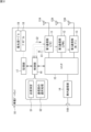
- FIG. 2 is a block diagram showing an example of the internal configuration of the vehicle gateway 10.
- the vehicle gateway 10 of this embodiment is a type of vehicle-mounted communication device that supports multiple types of wireless methods, and includes a first communication unit 11, a second communication unit 12, a third communication unit 13, an in-vehicle communication unit 14, a switch 15, a control unit 16, and a memory unit 17.
- the first communication unit 11 is, for example, a wireless device that complies with LTE.
- the first communication unit 11 includes an integrated circuit that performs modulation and demodulation of a physical layer and signal processing of a data link layer in accordance with LTE.
- An antenna 11A for LTE is connected to the first communication unit 11.
- the second communication unit 12 is, for example, a wireless device that complies with the LPWA.
- the second communication unit 112 includes an integrated circuit that performs modulation and demodulation of the physical layer and signal processing of the data link layer in accordance with the LPWA.
- An antenna 12A for the LPWA is connected to the second communication unit 12.
- the third communication unit 13 is, for example, a wireless device that complies with Wi-Fi.
- the third communication unit 13 includes an integrated circuit that performs modulation and demodulation of the physical layer and signal processing of the data link layer in accordance with the wireless LAN standard.
- a Wi-Fi antenna 13A is connected to the third communication unit 13.
- the in-vehicle communication unit 14 is a communication interface for in-vehicle communication.
- the in-vehicle communication unit 14 includes an integrated circuit that performs modulation and demodulation of the physical layer and signal processing of the data link layer in accordance with an in-vehicle communication standard such as CAN.
- the in-vehicle communication unit 14 is connected to a communication port 14A for in-vehicle communication.
- Each of the communication units 11, 12, and 13 can switch between different operation modes for communication based on the respective communication protocols.
- the operation modes include “enabled” and “disabled.”
- Enabled means that communication based on a predetermined communication protocol is executed.
- Disabled means that the communication is in a pause state or a sleep state.
- the type of operation mode is notified by the mode command C2 from the control unit 16.
- the switch 15 is an integrated circuit such as an LSI (Large Scale Integration) that has a relay function of the L2 and L3 layers.
- the first communication unit 11, the second communication unit 12, the third communication unit 13, the in-vehicle communication unit 14, and the control unit 16 are connected to the respective ports of the switch 15.
- the switch 15 and the control unit 16 may be implemented in a single integrated circuit such as a System on a Chip (SoC).
- SoC System on a Chip
- the switch 15 routes communication packets transmitted and received by the communication units 11, 12, and 13, the control unit 16, and the in-vehicle communication unit 14.
- the route information set in the switch 15 includes the following routes.
- Route 1 A route connecting the first communication unit 11 to the in-vehicle communication unit 14 and the control unit 11.
- Route 2 A route connecting the second communication unit 12 to the in-vehicle communication unit 14 and the control unit 11.
- Route 3 A route connecting the third communication unit 13 to the in-vehicle communication unit 14 and the control unit 11.
- the control unit 16 is an arithmetic processing device including one or more central processing units (CPUs) and a volatile memory.
- the control unit 16 may include a field programmable gate array (FPGA) or an application specific integrated circuit (ASIC).
- the control unit 16 is capable of control communication with the first communication unit 11, the second communication unit 12, and the third communication unit 13, using serial communication such as I2C (Inter-Integrated Circuit) (dashed arrows in the figure).
- I2C Inter-Integrated Circuit
- the control signals using serial communication include, for example, "radio wave detection C1" and "mode command C2.”
- the radio wave detection C1 is a control signal that each of the communication units 11, 12, and 13 transmits to the control unit 16. Specifically, each of the communication units 11, 12, and 13 transmits the radio wave detection C1 to the control unit 16 when it detects a radio wave of a predetermined frequency defined by its own communication protocol.
- the mode command C2 is a control signal with which the control unit 16 instructs each of the communication units 11, 12, and 13 on the type of operation mode.
- the control unit 16 determines the type of operation mode to be transmitted to each of the communication units 11, 12, and 13 according to the result of a selection process S2 described later. For example, when the first communication unit 11 is selected by the selection process S2, the control unit 16 sets the operation mode of the first communication unit 11 to "enabled” and the operation modes of the second communication unit 12 and the third communication unit 13 to "disabled.”
- the control unit 16 sets the operation mode of the second communication unit 12 to “enabled” and the operation modes of the third communication unit 13 and the first communication unit 11 to “disabled.”
- the control unit 16 sets the operation mode of the third communication unit 13 to "enabled” and the operation modes of the first communication unit 11 and the second communication unit 12 to “disabled.”
- the storage unit 17 is an auxiliary storage device including a non-volatile memory such as an Electrically Erasable Programmable ROM (EEPROM) and a flash Read Only Memory (ROM).
- the storage unit 17 stores, for example, a computer program 18 and a priority table 19.
- the computer program 18 includes, for example, a program for measuring communication quality based on Linux (registered trademark) and for causing the control unit 16 to execute a process for selecting a communication unit in accordance with the priority table 19.
- the priority table 19 will be described in detail later.
- the information processing executed by the control unit 16 of the vehicle gateway 10 includes at least the following processing.
- the quality measurement S1 is a process of measuring parameters indicating the communication quality of each of the communication units 11, 12, and 13.
- the communication quality to be measured includes, for example, RSSI (Received Signal Strength Indication, in dBm).
- the control unit 16 uses, for example, "iwlist” or “iwconfig” of Linux to acquire the RSSI of each of the communication units 11, 12, and 13.
- the RSSI can be measured regardless of the communication state (operation, pause, or sleep) of the communication units 11, 12, and 13.
- the communication quality to be measured may include network throughput (unit: Mbps).
- the control unit 16 acquires the network throughput of each of the communication units 11, 12, and 13, for example, by using "iperf" of Linux.
- the network throughput can be measured when the communication units 11, 12, and 13 are in operation.
- the communication quality to be measured may include a packet loss rate (unit: %).
- the packet loss rate can also be measured when the communication units 11, 12, and 13 are in operation.
- the control unit 16 measures the RSSI before each of the communication units 11, 12, and 13 establishes communication with a communication device outside the vehicle, for example, immediately after startup. After communication between each of the communication units 11, 12, and 13 and a communication device outside the vehicle is established, the control unit 16 measures at least one of the RSSI, the network throughput, and the packet loss rate.
- the communication unit selection process S2 is a process for selecting a connection target from among the multiple communication units 11, 12, and 13 for enabling the communication operation mode, based on the priority setting value defined by the priority table 19 and the measurement result of the quality measurement S1. Specifically, the selection process S2 includes the following processes.
- Process 1 A communication unit with a higher priority than the current priority is set as a connection candidate.
- Process 2 Measure the communication quality of the connection candidates.
- Process 3 If the communication quality of the connection candidate is equal to or higher than the reference value, the connection candidate is set as a connection target.
- Process 4 If the communication quality of the connection candidate is below the reference value, the connection candidate is excluded from the connection targets.
- Process 5 The communication unit with the next highest priority is set as a connection candidate, and processes 2 to 4 are repeated until a connection target is determined.
- the "next priority” refers to the next lowest priority after the current priority among the multiple priorities defined for each piece of configuration information in the priority table 19 (FIG. 3).
- the control unit 16 periodically executes quality measurement S1 and selection process S2, and if the communication quality of the currently operating communication units 11, 12, 13 is poor, it selects the communication units 11, 12, 13 with the next highest priority as connection candidates.
- the reference value of the communication quality is set for each type of parameter. For example, if the RSSI is -65 dBm or more at 2.4 GHz and -60 dBm or more at 5.0 GHz, the desired communication speed can be maintained. If the RSSI is -75 dBm or less, the radio waves may be too weak and the wireless connection may become unstable. Therefore, the reference value of the RSSI may be set to any one of ⁇ 65 dB, ⁇ 60 dBm, and 75 dBm according to the user's communication policy.
- the reference value of the network throughput may be set to a predetermined value within the above range according to the user's communication policy. However, when transmission of image or video data is assumed, it is preferable to set the reference value to 5 Mbps or more.
- the reference value of the network throughput may be set to any one of 1%, 3%, and 10% according to the user's communication policy.
- FIG. 3 is an explanatory diagram showing an example of the priority table 19.
- the priority table 19 is setting information in a table format in which communication types are arranged in a column direction and priority setting values for each communication type are arranged in a row direction.
- the communication types represent types of communication methods that can be executed by the multiple communication units 11, 12, and 13 included in the vehicle gateway 10.
- the communication types include, for example, "LTE,””OfficeWi-Fi,””TetheringWi-Fi,” and "LPWA.”
- the priority setting values for each communication type are set in advance by a user who operates the vehicle 1.
- the priority setting is executed, for example, from a command line of a management terminal such as a notebook PC that is communicatively connected to the control unit 16.
- the business Wi-Fi is, for example, a method of wireless communication with a wireless LAN router 4 installed in a business operated by the same owner as the owner of the vehicle 1. Therefore, in the case of the business Wi-Fi, no additional charge is incurred even if the third communication unit 13 is connected to the wireless LAN router 4.
- Tethering Wi-Fi is, for example, a method of communication using a tethering function of a mobile terminal held by the owner of the vehicle 1. Therefore, in the case of tethering Wi-Fi, there is a possibility that an additional fee will be charged when connecting the first communication unit 11 to a mobile terminal.
- the priority table 19 includes a plurality of pieces of configuration information (config 1 to config 3 in FIG. 3) that define the priority of each of the communication units 11, 12, and 13 for each of a plurality of policies.
- Config 1 is an example of priority settings when the policy places importance on communication speed.
- the priority of LTE is set to 10
- the priority of office Wi-Fi is set to 6
- the priority of tethering Wi-Fi is set to 3
- the priority of LPWA is set to 3.
- Config 2 is an example of setting priorities when the policy places importance on communication charges.
- the priority of LTE is set to 6
- the priority of office Wi-Fi is set to 10
- the priority of tethering Wi-Fi is set to 4
- the priority of LPWA is set to 8.
- FIG. 4 is a flowchart showing an example of a selection process S2 of the communication units 11, 12, and 13 executed by the control unit 16 of the vehicle gateway 10.
- "Uw”, "Un” and "Uc” are variables used in the selection process S2, and the definitions of each variable are as follows:
- Uw A variable indicating a communication unit among the multiple communication units 11, 12, and 13 whose operation mode is valid (hereinafter, referred to as the "current communication unit”).
- Un A variable that indicates, among the multiple communication units 11, 12, and 13, a communication unit whose operation mode is invalid (hereinafter, referred to as a "non-active communication unit”).
- Uc A variable representing a communication unit (hereinafter, referred to as a "connection candidate”) that is a candidate for switching the operation mode from invalid to valid among at least one non-active communication unit Un.
- the control unit 16 of the vehicle gateway 10 first determines whether or not the communication quality of the current communication unit Uw satisfies a reference value (step ST11).
- the communication quality may be, for example, at least one of RSSI, network throughput, and packet loss rate.
- “meeting the standard value” means “above the standard value” in the case of RSSI and network throughput, and means “below the standard value” in the case of packet loss rate.
- step ST11 determines whether or not a non-active communication unit Un has been detected (step ST12). Specifically, the control unit 16 determines whether or not the non-active communication unit Un has been detected based on whether or not a radio wave detection C1 has been received from the communication units 11, 12, and 13 other than the active communication unit Un.
- step ST12 determines whether or not the priority of the non-active communication unit Un is higher than the priority of the active communication unit Uw (step ST13).
- step ST13 If the determination result in step ST13 is negative, the control section 16 returns the process to before step ST11. If the determination result in step ST13 is positive, the control unit 16 sets the non-active communication unit Un, which has a higher priority than the active communication unit Uw, as a connection candidate Uc (step ST14).
- step ST11 determines whether the communication quality of the connection candidate Uc satisfies a reference value (step ST15).
- a reference value for example, RSSI is used as the communication quality.
- satisfying the reference value means “above the reference value” in the case of RSSI.
- step ST15 If the determination result in step ST15 is negative, the control unit 16 repeats the process (step ST17) of designating the non-active communication unit Un with the next priority as the connection candidate Uc until the determination result in step ST15 regarding the connection candidate Uc becomes positive. If the determination result in step ST15 is positive, the control unit 16 determines the connection candidate Uc as a connection target (step ST16), and returns the process to before step ST11.
- control unit 16 enables the operation mode of the communication unit determined to be the connection target among the multiple communication units 11, 12, and 13, and disables the operation modes of the other communication units.
- the connection candidate Uc determined as the connection target is switched to the active communication unit Uw, and the previous active communication unit Uw is switched to the non-active communication unit Un.
- the priority table 19 is exemplified as an example of priority setting information, but the data format of the setting information may be a text-based data format.
- text-based data formats that may be adopted include Comma Separated Values (CSV), Extensible Markup Language (XML), and JavaScript Object Notation (JSON).
- the priority table 19 (FIG. 3) is exemplified in which the larger the value, the higher the priority.
- the priority setting value may be defined so that the smaller the value, the higher the priority.
- the in-vehicle communication system 100 may include in-vehicle devices that perform in-vehicle communication independently without going through the ECU 30, such as sensors or actuators having a function of in-vehicle communication.
- Vehicle 1.
- Radio base station (LTE) 3 Wireless base station (LPWA) 4 Wireless LAN router 5 Public network 10
- Vehicle gateway (vehicle communication device) 11 First communication unit (LTE-compliant wireless device) 11A Antenna 12 Second communication unit (wireless device compliant with LPWA) 12A Antenna 13 Third communication unit (Wi-Fi compliant wireless device) 13A Antenna 14 In-vehicle communication unit 14A Communication port 15 Switch 16 Control unit 17 Storage unit 18 Computer program 19
- Priority table 30 ECU (on-vehicle communication device) 100 Vehicle-mounted communication system Uw Current communication unit Un Non-current communication unit Uc Connection candidate
Landscapes
- Engineering & Computer Science (AREA)
- Computer Networks & Wireless Communication (AREA)
- Signal Processing (AREA)
- Computer Security & Cryptography (AREA)
- Mobile Radio Communication Systems (AREA)
Abstract
本開示の一態様に係る装置は、複数種類の無線方式に対応する車載通信装置であって、準拠する通信プロトコルがそれぞれ異なる無線デバイスである複数の通信部と、前記複数の通信部にそれぞれ割り当てる優先度の設定情報を記憶する記憶部と、前記設定情報に基づいて、前記複数の通信部のうちで通信を有効とする1つの通信部を選択するための選択処理を実行する制御部と、を備え、前記選択処理は、通信が有効な通信部である現用通信部よりも優先度が高い通信部の通信品質が基準値を満たす場合に、当該優先度が高い前記通信部の通信を有効に切り替える処理を含む。
Description
本開示は、車載通信装置、通信部の選択方法、及びコンピュータプログラムに関する。
本出願は、2023年6月9日出願の日本出願第2023-95404号に基づく優先権を主張し、前記日本出願に記載された全ての記載内容を援用するものである。
本出願は、2023年6月9日出願の日本出願第2023-95404号に基づく優先権を主張し、前記日本出願に記載された全ての記載内容を援用するものである。
特許文献1には、通信のデータ量や発生状態を考慮して、Wi-Fi(登録商標)で接続するアクセスポイントを切り替える車載通信装置が記載されている。
具体的には、特許文献1の車載通信装置では、起動したアプリケーションに対応して設定される優先順位に従って、無線通信のアクセスポイントが選択される。
具体的には、特許文献1の車載通信装置では、起動したアプリケーションに対応して設定される優先順位に従って、無線通信のアクセスポイントが選択される。
本開示の一態様に係る装置は、複数種類の無線方式に対応する車載通信装置であって、準拠する通信プロトコルがそれぞれ異なる無線デバイスである複数の通信部と、前記複数の通信部にそれぞれ割り当てる優先度の設定情報を記憶する記憶部と、前記設定情報に基づいて、前記複数の通信部のうちで通信を有効とする1つの通信部を選択するための選択処理を実行する制御部と、を備え、前記選択処理は、通信が有効な通信部である現用通信部よりも優先度が高い通信部の通信品質が基準値を満たす場合に、当該優先度が高い前記通信部の通信を有効に切り替える処理を含む。
<本開示が解決しようとする課題>
車載通信装置の一種として、LTE(登録商標)やWi-Fi(登録商標)など、準拠する通信プロトコルがそれぞれ異なる複数の通信インタフェース(以下、「通信部」ともいう。)を有する通信装置がある。
上記の車載通信装置では、インターネットなどに接続するため、利用可能な通信部の中から有効とする通信部が選択される。ここで、スマートフォンの場合は、電波強度が弱く通信不能になった際に、ユーザが手動で通信部を切り替えることができる。
車載通信装置の一種として、LTE(登録商標)やWi-Fi(登録商標)など、準拠する通信プロトコルがそれぞれ異なる複数の通信インタフェース(以下、「通信部」ともいう。)を有する通信装置がある。
上記の車載通信装置では、インターネットなどに接続するため、利用可能な通信部の中から有効とする通信部が選択される。ここで、スマートフォンの場合は、電波強度が弱く通信不能になった際に、ユーザが手動で通信部を切り替えることができる。
しかし、車載通信装置の場合は、設置場所によってはユーザが手動で通信部を切り替えることが難しい場合が想定される。このため、状況に応じて自動的に適切な通信部を選択する仕組みを車載通信装置に組み込む必要がある。
一方、優先度のみを規準として通信部を選択すると、通信品質が悪い通信部が選択される可能性がある。更に、利用中の通信部の通信品質が悪化すると、他の通信部への切り替えを行わないと通信不能な状態が継続することになる。
一方、優先度のみを規準として通信部を選択すると、通信品質が悪い通信部が選択される可能性がある。更に、利用中の通信部の通信品質が悪化すると、他の通信部への切り替えを行わないと通信不能な状態が継続することになる。
本開示は、上記の問題点に鑑み、利用すべき通信部を適切に選択できる車載通信装置等を提供することを目的とする。
<本開示の効果>
本開示によれば、利用すべき通信部を適切に選択することができる。
本開示によれば、利用すべき通信部を適切に選択することができる。
<本開示の実施形態の概要>
以下、本開示の実施形態の概要を列記して説明する。
以下、本開示の実施形態の概要を列記して説明する。
(1) 本実施形態に係る装置は、複数種類の無線方式に対応する車載通信装置であって、準拠する通信プロトコルがそれぞれ異なる無線デバイスである複数の通信部と、前記複数の通信部にそれぞれ割り当てる優先度の設定情報を記憶する記憶部と、前記設定情報に基づいて、前記複数の通信部のうちで通信を有効とする1つの通信部を選択するための選択処理を実行する制御部と、を備え、前記選択処理は、通信が有効な通信部である現用通信部よりも優先度が高い通信部の通信品質が基準値を満たす場合に、当該優先度が高い前記通信部の通信を有効に切り替える処理を含む。
本実施形態の車載通信装置によれば、通信が有効な通信部である現用通信部よりも優先度が高い通信部の通信品質が基準値を満たす場合に、当該優先度が高い通信部の通信が有効に切り替えられる。
このため、通信品質の悪化を防止しつつ、現用通信部よりも優先度が高い通信部の通信が有効にできる。従って、利用すべき通信部を適切に選択することができる。
このため、通信品質の悪化を防止しつつ、現用通信部よりも優先度が高い通信部の通信が有効にできる。従って、利用すべき通信部を適切に選択することができる。
(2) 上述の(1)の車載通信装置において、前記選択処理は、更に、前記現用通信部の通信品質が基準値を満たさず、かつ、前記現用通信部の優先度の次の優先度の通信部の通信品質が基準値を満たす場合に、当該次の優先度の通信部を有効に切り替える処理を含んでもよい。
本実施形態の車載通信装置によれば、現用通信部の通信品質が基準値を満たさず、かつ、現用通信部の優先度の次の優先度の通信部の通信品質が基準値を満たす場合に、当該次の優先度の通信部が有効に切り替えられる。
このため、現用通信部の通信品質が悪化した場合に、通信品質の悪化を防止しつつ、次の優先度の通信部の通信を有効にできる。従って、現用通信部の通信品質が悪化した場合でも、利用すべき通信部を適切に選択することができる。
このため、現用通信部の通信品質が悪化した場合に、通信品質の悪化を防止しつつ、次の優先度の通信部の通信を有効にできる。従って、現用通信部の通信品質が悪化した場合でも、利用すべき通信部を適切に選択することができる。
(3) 上述の(1)又は(2)の車載通信装置において、前記設定情報は、複数のポリシーごとに前記複数の通信部の優先度を定義した複数のコンフィグ情報を含むことにしてもよい。
この場合、複数のコンフィグ情報ののうちのいずれかをユーザが選択することにより、ユーザが所望するポリシーに基づく選択処理を実現することができる。
この場合、複数のコンフィグ情報ののうちのいずれかをユーザが選択することにより、ユーザが所望するポリシーに基づく選択処理を実現することができる。
(4) 上述の(3)の車載通信装置において、前記複数のコンフィグ情報は、前記ポリシーが通信速度の重視である第1コンフィグ情報と、前記ポリシーが通信料金の重視である第2コンフィグ情報と、前記ポリシーが通信料金の無料である第3コンフィグ情報と、を含んでもよい。
この場合、上記のいずれかのコンフィグ情報をユーザが選択することにより、通信速度の重視、通信料金の重視、及び通信料金の無料のうちのいずれかのポリシーに基づく選択処理を実現することができる。
この場合、上記のいずれかのコンフィグ情報をユーザが選択することにより、通信速度の重視、通信料金の重視、及び通信料金の無料のうちのいずれかのポリシーに基づく選択処理を実現することができる。
(5) 上述の(1)から(4)のいずれかの車載通信装置において、前記複数の通信部は、LTEに準拠する無線デバイスである第1通信部と、LPWAに準拠する無線デバイスである第2通信部と、Wi-Fiに準拠する無線デバイスである第3通信部と、を含んでもよい。
この場合、少なくとも第1通信部、第2通信部、及び第3通信部の中から、利用すべき通信部を適切に選択できるようになる。
この場合、少なくとも第1通信部、第2通信部、及び第3通信部の中から、利用すべき通信部を適切に選択できるようになる。
(6) 上述の(1)から(5)のいずれかの車載通信装置において、前記制御部は、車外の通信装置との通信確立前においては、前記通信品質を表すパラメータとしてRSSIを採用し、当該RSSIの測定結果を用いて前記選択処理を実行してもよい。
その理由は、RSSIは、各通信部の通信状態(動作、休止、又はスリープ)に関係なく測定可能であるから、通信確立前に利用するパラメータとして好ましいからである。
その理由は、RSSIは、各通信部の通信状態(動作、休止、又はスリープ)に関係なく測定可能であるから、通信確立前に利用するパラメータとして好ましいからである。
(7) 上述の(1)から(6)のいずれかの車載通信装置において、前記制御部は、車外の通信装置との通信確立後においては、前記通信品質を表すパラメータとしてRSSI、ネットワークスループット、及びパケット損失率のうちの少なくとも1つのパラメータを採用し、当該パラメータの測定結果を用いて前記選択処理を実行してもよい。
その理由は、通信確立後においては、測定可能な複数種類のパラメータの利用を許容すれば、RSSIに限定する場合に比べて選択処理をより確実に実行できるからである。
その理由は、通信確立後においては、測定可能な複数種類のパラメータの利用を許容すれば、RSSIに限定する場合に比べて選択処理をより確実に実行できるからである。
(8) 本実施形態に係る方法は、上述の(1)から(7)の車載中継装置が実行する通信部の選択方法である。
従って、本実施形態の選択方法は、上述の(1)から(7)の車載通信装置と同様の作用効果を奏する。
従って、本実施形態の選択方法は、上述の(1)から(7)の車載通信装置と同様の作用効果を奏する。
(9) 本実施形態に係るコンピュータプログラムは、上述の(1)から(7)の車載通信装置としてコンピュータを機能させるためのコンピュータプログラムである。
従って、本実施形態のコンピュータプログラムは、上述の(1)から(7)の車載通信装置と同様の作用効果を奏する。
従って、本実施形態のコンピュータプログラムは、上述の(1)から(7)の車載通信装置と同様の作用効果を奏する。
<本発明の実施形態の詳細>
以下、図面を参照して、本発明の実施形態の詳細を説明する。なお、以下に記載する実施形態の少なくとも一部を任意に組み合わせてもよい。
以下、図面を参照して、本発明の実施形態の詳細を説明する。なお、以下に記載する実施形態の少なくとも一部を任意に組み合わせてもよい。
〔車載通信システムの構成例〕
図1は、車載通信システム100の構成例を示すネットワーク構成図である。
図1に示すように、本実施形態の車載通信システム100は、車両1の内部に構築された車載LAN(Local Area Network)である。
車載通信システム100は、ネットワークを構成する車載通信装置(通信ノード)として、車載ゲートウェイ10とECU(Electric Control Unit)30とを備える。
図1は、車載通信システム100の構成例を示すネットワーク構成図である。
図1に示すように、本実施形態の車載通信システム100は、車両1の内部に構築された車載LAN(Local Area Network)である。
車載通信システム100は、ネットワークを構成する車載通信装置(通信ノード)として、車載ゲートウェイ10とECU(Electric Control Unit)30とを備える。
車載通信システム100の車内通信のプロトコルには、例えば、CAN(Control Area Network:登録商標)、CAN-FD(CAN with flexible data rate)、LIN(Local Interconnect Network)、FlexRay(登録商標)、或いはイーサネット(登録商標)などを採用し得る。
車載通信システム100の車内通信の通信方式は、上記に列挙したプロトコルのうちの少なくとも2つのプロトコルが混在する通信方式であってもよい。
車載通信システム100の車内通信の通信方式は、上記に列挙したプロトコルのうちの少なくとも2つのプロトコルが混在する通信方式であってもよい。
車載ゲートウェイ10は、複数種類の無線方式により車両1の外部との情報通信が可能な通信装置である。
複数種類の無線方式には、例えば、LTE(Long Term Evolution:登録商標)、LPWA(Low Power Wide Area)、及びWi-Fi(登録商標)が含まれる。従って、車載ゲートウェイ10は、LTEの無線基地局2を介してインターネットを含む公衆ネットワーク5と接続可能である。
複数種類の無線方式には、例えば、LTE(Long Term Evolution:登録商標)、LPWA(Low Power Wide Area)、及びWi-Fi(登録商標)が含まれる。従って、車載ゲートウェイ10は、LTEの無線基地局2を介してインターネットを含む公衆ネットワーク5と接続可能である。
同様に、車載ゲートウェイ10は、LPWAの無線基地局3を介して公衆ネットワーク5と接続可能であり、車載ゲートウェイ10は、無線LANルータ4を介して公衆ネットワーク5と接続可能である。
ECU30は、車両1に搭載されたセンサ又はアクチュエータなどの各種の車載機器を制御する車両用の電子制御ユニットである。
ECU30は、車両1に搭載されたセンサ又はアクチュエータなどの各種の車載機器を制御する車両用の電子制御ユニットである。
車両1内の制御対象に着目すると、ECU30の種類には、エンジン制御ECU、トランスミッション制御ECU、パワーステアリング制御ECU、エアコン制御ECU、及びAV(Audio/Visual)系制御ECUなどが含まれる。
ECU30は、自身に接続されるセンサ(速度センサ、加速度センサ、温度センサ、及び圧力センサなど)の計測情報をシステムに取り込んだり、計測情報に基づいて、自身に接続される各種のアクチュエータ(電動モータなど)を制御したりする。
ECU30は、自身に接続されるセンサ(速度センサ、加速度センサ、温度センサ、及び圧力センサなど)の計測情報をシステムに取り込んだり、計測情報に基づいて、自身に接続される各種のアクチュエータ(電動モータなど)を制御したりする。
〔車載ゲートウェイの構成例〕
図2は、車載ゲートウェイ10の内部構成の一例を示すブロック図である。
図2に示すように、本実施形態の車載ゲートウェイ10は、複数種類の無線方式に対応する車載通信装置の一種であり、第1通信部11、第2通信部12、第3通信部13、車内通信部14、スイッチ15、制御部16、及び記憶部17を備える。
図2は、車載ゲートウェイ10の内部構成の一例を示すブロック図である。
図2に示すように、本実施形態の車載ゲートウェイ10は、複数種類の無線方式に対応する車載通信装置の一種であり、第1通信部11、第2通信部12、第3通信部13、車内通信部14、スイッチ15、制御部16、及び記憶部17を備える。
第1通信部11は、例えばLTEに準拠する無線デバイスである。第1通信部11は、LTEに則った物理層の変復調とデータリンク層の信号処理を行う集積回路を含む。第1通信部11には、LTE用のアンテナ11Aが接続される。
第2通信部12は、例えばLPWAに準拠する無線デバイスである。第2通信部112、LPWAに則った物理層の変復調とデータリンク層の信号処理を行う集積回路を含む。第2通信部12には、LPWA用のアンテナ12Aが接続される。
第2通信部12は、例えばLPWAに準拠する無線デバイスである。第2通信部112、LPWAに則った物理層の変復調とデータリンク層の信号処理を行う集積回路を含む。第2通信部12には、LPWA用のアンテナ12Aが接続される。
第3通信部13は、例えばWi-Fiに準拠する無線デバイスである。第3通信部13は、無線LAN規格に則った物理層の変復調とデータリンク層の信号処理を行う集積回路を含む。第3通信部13には、Wi-Fi用のアンテナ13Aが接続される。
車内通信部14は、車内通信用の通信インタフェースである。車内通信部14は、CANなどの車内通信規格に則った、物理層の変復調とデータリンク層の信号処理を行う集積回路を含む。車内通信部14は、車内通信用の通信ポート14Aに接続される。
車内通信部14は、車内通信用の通信インタフェースである。車内通信部14は、CANなどの車内通信規格に則った、物理層の変復調とデータリンク層の信号処理を行う集積回路を含む。車内通信部14は、車内通信用の通信ポート14Aに接続される。
各通信部11,12,13は、各々の通信プロトコルに基づく通信の動作モードの種別を切り替え可能である。動作モードの種別には、「有効」(イネーブル)と「無効」(ディゼーブル)が含まれる。
「有効」は、所定の通信プロトコルに基づく通信を実行することを意味する。「無効」は、当該通信を休止状態又はスリープ状態にすることを意味する。動作モードの種別は、制御部16からのモード指令C2により通知される。
「有効」は、所定の通信プロトコルに基づく通信を実行することを意味する。「無効」は、当該通信を休止状態又はスリープ状態にすることを意味する。動作モードの種別は、制御部16からのモード指令C2により通知される。
スイッチ15は、L2及びL3レイヤの中継機能を有する、例えばLSI(Large Scale Integration)などの集積回路である。
スイッチ15の各ポートには、第1通信部11、第2通信部12、第3通信部13、車内通信部14、及び制御部16が接続される。スイッチ15と制御部16は、例えばSoC(System on a Chip)などの1つの集積回路に実装してもよい。
スイッチ15の各ポートには、第1通信部11、第2通信部12、第3通信部13、車内通信部14、及び制御部16が接続される。スイッチ15と制御部16は、例えばSoC(System on a Chip)などの1つの集積回路に実装してもよい。
スイッチ15は、ユーザ設定による静的な経路情報に従って、各通信部11,12,13、制御部16、及び車内通信部14が送受信する通信パケットのルーティングを行う。具体的には、スイッチ15に設定される経路情報には、以下の経路が含まれる。
経路1:第1通信部11を車内通信部14と制御部11と接続する経路
経路2:第2通信部12を車内通信部14と制御部11と接続する経路
経路3:第3通信部13を車内通信部14と制御部11と接続する経路
経路1:第1通信部11を車内通信部14と制御部11と接続する経路
経路2:第2通信部12を車内通信部14と制御部11と接続する経路
経路3:第3通信部13を車内通信部14と制御部11と接続する経路
制御部16は、1又は複数のCPU(Central Processing Unit)及び揮発性メモリを含む演算処理装置である。制御部16は、FPGA(Field Programmable Gate Array)又はASIC(Application Specific Integrated Circuit)を含んでもよい。
制御部16は、例えばI2C(Inter-Integrated Circuit)などのシリアル通信(図示の破線矢印)を利用した、第1通信部11、第2通信部12、及び第3通信部13との制御通信が可能である。
制御部16は、例えばI2C(Inter-Integrated Circuit)などのシリアル通信(図示の破線矢印)を利用した、第1通信部11、第2通信部12、及び第3通信部13との制御通信が可能である。
シリアル通信を用いた制御信号には、例えば「電波検知C1」及び「モード指令C2」が含まれる。
電波検知C1は、各通信部11,12,13がそれぞれ制御部16に送信する制御信号である。具体的には、各通信部11,12,13は、自身の通信プロトコルにて規定される所定周波数の電波を検出した場合に、電波検知C1を制御部16に送信する。
電波検知C1は、各通信部11,12,13がそれぞれ制御部16に送信する制御信号である。具体的には、各通信部11,12,13は、自身の通信プロトコルにて規定される所定周波数の電波を検出した場合に、電波検知C1を制御部16に送信する。
モード指令C2は、制御部16が各通信部11,12,13に動作モードの種別を指示する制御信号である。制御部16は、後述の選択処理S2の結果に応じて、各通信部11,12,13に送信する動作モードの種別を決定する。
例えば、選択処理S2により第1通信部11が選択された場合は、制御部16は、第1通信部11の動作モードを「有効」とし、第2通信部12及び第3通信部13の動作モードを「無効」とする。
例えば、選択処理S2により第1通信部11が選択された場合は、制御部16は、第1通信部11の動作モードを「有効」とし、第2通信部12及び第3通信部13の動作モードを「無効」とする。
同様に、選択処理S2により第2通信部12が選択された場合は、制御部16は、第2通信部12の動作モードを「有効」とし、第3通信部13及び第1通信部11の動作モードを「無効」とする。
また、選択処理S2により第3通信部13が選択された場合は、制御部16は、第3通信部13の動作モードを「有効」とし、第1通信部11及び第2通信部12の動作モードを「無効」とする。
また、選択処理S2により第3通信部13が選択された場合は、制御部16は、第3通信部13の動作モードを「有効」とし、第1通信部11及び第2通信部12の動作モードを「無効」とする。
記憶部17は、EEPROM(Electrically Erasable Programmable ROM)及びフラッシュROM(Read Only Memory)などの不揮発性メモリを含む補助記憶装置である。
記憶部17には、例えばコンピュータプログラム18と優先度テーブル19が格納される。コンピュータプログラム18には、例えばLinux(登録商標)ベースの通信品質の測定、及び、優先度テーブル19に則った通信部の選択処理を制御部16に実行させるプログラムが含まれる。優先度テーブル19の詳細は後述する。
記憶部17には、例えばコンピュータプログラム18と優先度テーブル19が格納される。コンピュータプログラム18には、例えばLinux(登録商標)ベースの通信品質の測定、及び、優先度テーブル19に則った通信部の選択処理を制御部16に実行させるプログラムが含まれる。優先度テーブル19の詳細は後述する。
〔制御部による情報処理〕
図2に示すように、車載ゲートウェイ10の制御部16が実行する情報処理には、少なくとも以下の処理が含まれる。
S1:品質測定
S2:通信部の選択処理
図2に示すように、車載ゲートウェイ10の制御部16が実行する情報処理には、少なくとも以下の処理が含まれる。
S1:品質測定
S2:通信部の選択処理
品質測定S1は、各通信部11,12,13の通信品質を表すパラメータを測定する処理である。測定対象の通信品質は、例えばRSSI(Received Signal Strength Indication:単位はdBm)を含む。
制御部16は、例えばLinuxの「iwlist」又は「iwconfig」などを利用して、各通信部11,12,13のRSSIを取得する。RSSIは、通信部11,12,13の通信状態(動作、休止、又はスリープ)に関係なく測定可能である。
制御部16は、例えばLinuxの「iwlist」又は「iwconfig」などを利用して、各通信部11,12,13のRSSIを取得する。RSSIは、通信部11,12,13の通信状態(動作、休止、又はスリープ)に関係なく測定可能である。
測定対象の通信品質は、ネットワークスループット(単位はMbps)を含んでもよい。制御部16は、例えばLinuxの「iperf」を利用して、各通信部11,12,13のネットワークスループットを取得する。ネットワークスループットは、通信部11,12,13が動作中である場合に測定可能である。
測定対象の通信品質は、パケット損失率(単位は%)を含んでもよい。パケット損失率も、通信部11,12,13が動作中である場合に測定可能である。
測定対象の通信品質は、パケット損失率(単位は%)を含んでもよい。パケット損失率も、通信部11,12,13が動作中である場合に測定可能である。
従って、制御部16は、例えば起動直後など、各通信部11,12,13が車外の通信装置と通信を確立する前においては、RSSIを測定対象とする。
また、制御部16は、各通信部11,12,13と車外の通信装置との通信が確立した後においては、RSSI、ネットワークスループット、及びパケット損失率のうちの少なくとも1つを測定対象とする。
また、制御部16は、各通信部11,12,13と車外の通信装置との通信が確立した後においては、RSSI、ネットワークスループット、及びパケット損失率のうちの少なくとも1つを測定対象とする。
通信部の選択処理S2は、優先度テーブル19により定義された優先度の設定値と、品質測定S1の測定結果とに基づいて、複数の通信部11,12,13のうち通信の動作モードを有効とする接続対象を選択する処理である。具体的には、選択処理S2には以下の処理が含まれる。
処理1:優先度が現状よりも高い通信部を接続候補とする。
処理2:接続候補の通信品質を測定する。
処理3:接続候補の通信品質が基準値以上の場合、接続候補を接続対象とする。
処理4:接続候補の通信品質が基準値未満の場合、接続候補を接続対象から外す。
処理5:次の優先度の通信部を接続候補に設定し、接続対象が決定されるまで処理2から処理4を繰り返す。
処理2:接続候補の通信品質を測定する。
処理3:接続候補の通信品質が基準値以上の場合、接続候補を接続対象とする。
処理4:接続候補の通信品質が基準値未満の場合、接続候補を接続対象から外す。
処理5:次の優先度の通信部を接続候補に設定し、接続対象が決定されるまで処理2から処理4を繰り返す。
なお、「次の優先度」とは、優先度テーブル19(図3)においてコンフィグ情報ごとに定義される複数の優先度のうち、現状の優先度の次に低い優先度ことである。
制御部16は、品質測定S1と選択処理S2を定期的に実行し、現時点で動作中の通信部11,12,13の通信品質が悪い場合は、次の優先度の通信部11,12,13を接続候補とする。
制御部16は、品質測定S1と選択処理S2を定期的に実行し、現時点で動作中の通信部11,12,13の通信品質が悪い場合は、次の優先度の通信部11,12,13を接続候補とする。
〔通信品質の基準値〕
通信品質の基準値は、パラメータの種別ごとに設定される。
例えば、RSSIについては、2.4GHz場合で-65dBm以上、5.0GHzの場合で-60dBm以上であれば、所望の通信速度を維持できる。また、RSSIが-75dBm以下になると、電波が弱すぎて無線接続が不安定になる可能性がある。
従って、RSSIの基準値は、ユーザの通信ポリシーに応じて、-65dB、-60dBm、及び75dBmのうちのいずれかに設定すればよい。
通信品質の基準値は、パラメータの種別ごとに設定される。
例えば、RSSIについては、2.4GHz場合で-65dBm以上、5.0GHzの場合で-60dBm以上であれば、所望の通信速度を維持できる。また、RSSIが-75dBm以下になると、電波が弱すぎて無線接続が不安定になる可能性がある。
従って、RSSIの基準値は、ユーザの通信ポリシーに応じて、-65dB、-60dBm、及び75dBmのうちのいずれかに設定すればよい。
ネットワークスループットは、例えばテキストデータを適切に伝送したい場合は、下り0.128~1.0Mbpsが目安となる。
従って、ネットワークスループットの基準値は、ユーザの通信ポリシーに応じて、上記の数値範囲に含まれる所定値とすればよい。もっとも、画像又は動画データの伝送を想定する場合には、基準値を5Mbps以上に設定することが好ましい。
従って、ネットワークスループットの基準値は、ユーザの通信ポリシーに応じて、上記の数値範囲に含まれる所定値とすればよい。もっとも、画像又は動画データの伝送を想定する場合には、基準値を5Mbps以上に設定することが好ましい。
パケット損失率は、1%未満であれば通信が快適であるとされ、3%を超えると再送信が増えて反応が悪く感じられることが多い。また、10%を超えるとユーザにストレスに感じさせるとされている。
従って、ネットワークスループットの基準値は、ユーザの通信ポリシーに応じて、1%、3%、及び10%のうちのいずれかに設定すればよい。
従って、ネットワークスループットの基準値は、ユーザの通信ポリシーに応じて、1%、3%、及び10%のうちのいずれかに設定すればよい。
〔優先度テーブル〕
図3は、優先度テーブル19の一例を示す説明図である。
図3に示すように、優先度テーブル19は、通信種別が列方向に並び通信種別ごとの優先度の設定値が行方向に並ぶように定義される、テーブル形式の設定情報である。通信種別は、車載ゲートウェイ10に含まれる複数の通信部11,12,13により実行可能な通信方式の種別を表す。
図3は、優先度テーブル19の一例を示す説明図である。
図3に示すように、優先度テーブル19は、通信種別が列方向に並び通信種別ごとの優先度の設定値が行方向に並ぶように定義される、テーブル形式の設定情報である。通信種別は、車載ゲートウェイ10に含まれる複数の通信部11,12,13により実行可能な通信方式の種別を表す。
通信種別には、例えば「LTE」、「事業所Wi-Fi」、「テザリングWi-Fi」、及び「LPWA」が含まれる。
通信種別ごとの優先度の設定値は、車両1を運用するユーザにより予め設定される。優先度の設定は、例えば、制御部16と通信可能に接続されたノートPCなどの管理端末のコマンドラインから実行される。
通信種別ごとの優先度の設定値は、車両1を運用するユーザにより予め設定される。優先度の設定は、例えば、制御部16と通信可能に接続されたノートPCなどの管理端末のコマンドラインから実行される。
事業所Wi-Fiは、例えば、車両1の所有者と同じ所有者が運用する事業所に設置された無線LANルータ4と無線通信する方式である。従って、事業所Wi-Fiの場合には、第3通信部13を無線LANルータ4と接続しても追加料金はかからない。
テザリングWi-Fiは、例えば、車両1の所有者が保持する携帯端末のテザリング機能により通信する方式である。従って、テザリングWi-Fiの場合には、第1通信部11を携帯端末に接続すると追加料金がかかる可能性がある。
テザリングWi-Fiは、例えば、車両1の所有者が保持する携帯端末のテザリング機能により通信する方式である。従って、テザリングWi-Fiの場合には、第1通信部11を携帯端末に接続すると追加料金がかかる可能性がある。
図3に示すように、優先度テーブル19には、複数のポリシーごとに各通信部11,12,13の優先度を定義した複数のコンフィグ情報(図3のコンフィグ1からコンフィグ3)が含まれる。
具体的には、コンフィグ1は、ポリシーが通信速度の重視である場合の優先度の設定例である。この場合、例えば、LTEの優先度=10、事業所Wi-Fiの優先度=6、テザリングWi-Fiの優先度=3、及び、LPWAの優先度=3に設定される。
具体的には、コンフィグ1は、ポリシーが通信速度の重視である場合の優先度の設定例である。この場合、例えば、LTEの優先度=10、事業所Wi-Fiの優先度=6、テザリングWi-Fiの優先度=3、及び、LPWAの優先度=3に設定される。
コンフィグ2は、ポリシーが通信料金の重視である場合の優先度の設定例である。この場合、例えば、LTEの優先度=6、事業所Wi-Fiの優先度=10、テザリングWi-Fiの優先度=4、LPWAの優先度=8に設定される。
コンフィグ3は、ポリシーが通信料金の完全無料である場合の優先度の設定例である。この場合、例えば、LTEの優先度=0、事業所Wi-Fiの優先度=10、テザリングWi-Fiの優先度=0、LPWAの優先度=0に設定される。
コンフィグ3は、ポリシーが通信料金の完全無料である場合の優先度の設定例である。この場合、例えば、LTEの優先度=0、事業所Wi-Fiの優先度=10、テザリングWi-Fiの優先度=0、LPWAの優先度=0に設定される。
〔通信部の選択処理〕
図4は、車載ゲートウェイ10の制御部16が実行する、通信部11,12,13の選択処理S2の一例を示すフローチャートである。
図4において、「Uw」、「Un」及び「Uc」は、選択処理S2に用いられる変数であり、各変数の定義は次の通りである。
図4は、車載ゲートウェイ10の制御部16が実行する、通信部11,12,13の選択処理S2の一例を示すフローチャートである。
図4において、「Uw」、「Un」及び「Uc」は、選択処理S2に用いられる変数であり、各変数の定義は次の通りである。
Uw:複数の通信部11,12,13のうち、動作モードが有効である通信部(以下、「現用通信部」という。)を表す変数である。
Un:複数の通信部11,12,13のうち、動作モードが無効である通信部(以下、「非現用通信部」という。)を表す変数である。
Uc:少なくとも1つの非現用通信部Unのうち、動作モードを無効から有効に切り替え得る候補とする通信部(以下、「接続候補」という。)を表す変数である。
Un:複数の通信部11,12,13のうち、動作モードが無効である通信部(以下、「非現用通信部」という。)を表す変数である。
Uc:少なくとも1つの非現用通信部Unのうち、動作モードを無効から有効に切り替え得る候補とする通信部(以下、「接続候補」という。)を表す変数である。
図4に示すように、車載ゲートウェイ10の制御部16は、まず、現用通信部Uwの通信品質が基準値を満たすか否かを判定する(ステップST11)。
この場合の通信品質には、例えばRSSI、ネットワークスループット、及びパケット損失率のうちの少なくとも1つを採用し得る。また、「基準値を満たす」とは、RSSIとネットワークスループットの場合は「基準値以上」を意味し、パケット損失率の場合は「基準値未満」を意味する。
この場合の通信品質には、例えばRSSI、ネットワークスループット、及びパケット損失率のうちの少なくとも1つを採用し得る。また、「基準値を満たす」とは、RSSIとネットワークスループットの場合は「基準値以上」を意味し、パケット損失率の場合は「基準値未満」を意味する。
ステップST11の判定結果が肯定である場合は、制御部16は、非現用通信部Unを検知したか否かを判定する(ステップST12)。
具体的には、制御部16は、現用通信部Un以外の通信部11,12,13からの電波検知C1を受信したか否かにより、非現用通信部Unを検知したか否かを判定する。
具体的には、制御部16は、現用通信部Un以外の通信部11,12,13からの電波検知C1を受信したか否かにより、非現用通信部Unを検知したか否かを判定する。
ステップST12の判定結果が否定である場合は、制御部16は、処理をステップST11の前に戻す。
ステップST12の判定結果が肯定である場合は、制御部16は、優先度テーブル19を参照して、非現用通信部Unの優先度が現用通信部Uwの優先度よりも高いか否かを判定する(ステップST13)。
ステップST12の判定結果が肯定である場合は、制御部16は、優先度テーブル19を参照して、非現用通信部Unの優先度が現用通信部Uwの優先度よりも高いか否かを判定する(ステップST13)。
ステップST13の判定結果が否定である場合は、制御部16は、処理をステップST11の前に戻す。
ステップST13の判定結果が肯定である場合は、制御部16は、現用通信部Uwよりも優先度が高い非現用通信部Unを接続候補Ucとする(ステップST14)。
ステップST13の判定結果が肯定である場合は、制御部16は、現用通信部Uwよりも優先度が高い非現用通信部Unを接続候補Ucとする(ステップST14)。
ステップST11の判定結果が否定である場合は、制御部16は、優先度テーブル19を参照して、現用通信部Uwの優先度に対して次の優先度を有する非現用通信部Unを接続候補Ucとする(ステップST17)。
次に、制御部16は、接続候補Ucの通信品質が基準値を満たすか否かを判定する(ステップST15)。この場合の通信品質には、例えばRSSIが採用される。また、「基準値を満たす」とは、RSSIの場合は「基準値以上」を意味する。
次に、制御部16は、接続候補Ucの通信品質が基準値を満たすか否かを判定する(ステップST15)。この場合の通信品質には、例えばRSSIが採用される。また、「基準値を満たす」とは、RSSIの場合は「基準値以上」を意味する。
ステップST15の判定結果が否定である場合は、制御部16は、接続候補Ucに関するステップST15の判定結果が肯定になるまで、次の優先度の非現用通信部Unを接続候補Ucとする処理(ステップST17)を繰り返す。
ステップST15の判定結果が肯定である場合は、制御部16は、接続候補Ucを、接続対象に決定し(ステップST16)、処理をステップST11の前に戻す。
ステップST15の判定結果が肯定である場合は、制御部16は、接続候補Ucを、接続対象に決定し(ステップST16)、処理をステップST11の前に戻す。
具体的には、制御部16は、複数の通信部11,12,13のうち、接続対象に決定した通信部の動作モードを有効とし、それ以外の通信部の動作モードを無効とする。
これにより、接続対象と決定した接続候補Ucが現用通信部Uwに切り替わり、従前の現用通信部Uwが非現用通信部Unに切り替わる。
これにより、接続対象と決定した接続候補Ucが現用通信部Uwに切り替わり、従前の現用通信部Uwが非現用通信部Unに切り替わる。
〔その他の変形例〕
今回開示した実施形態はすべての点で例示であって制限的なものではない。本発明の権利範囲は、上述の実施形態に限定されるものではなく、請求の範囲に記載された構成と均等の範囲内でのすべての変更が含まれる。
今回開示した実施形態はすべての点で例示であって制限的なものではない。本発明の権利範囲は、上述の実施形態に限定されるものではなく、請求の範囲に記載された構成と均等の範囲内でのすべての変更が含まれる。
上述の実施形態では、優先度の設定情報の一例として優先度テーブル19を例示したが、設定情報のデータ形式はテキストベースのデータ形式であってもよい。
テキストベースのデータ形式としては、例えば、CSV(Comma Separated Values)、XML(Extensible Markup Language)、及びJSON(JavaScript Object Notation)などを採用し得る。
テキストベースのデータ形式としては、例えば、CSV(Comma Separated Values)、XML(Extensible Markup Language)、及びJSON(JavaScript Object Notation)などを採用し得る。
上述の実施形態では、値が大きいほど優先度が高い優先度テーブル19(図3)を例示したが、値が小さいほど優先度が高くなるように優先度の設定値を定義してもよい。
上述の実施形態において、車載通信システム100には、例えば車内通信の機能を有するセンサ又はアクチュエータなど、ECU30を介さずに独自に車内通信を行う車載機器が含まれていてもよい。
上述の実施形態において、車載通信システム100には、例えば車内通信の機能を有するセンサ又はアクチュエータなど、ECU30を介さずに独自に車内通信を行う車載機器が含まれていてもよい。
1 車両
2 無線基地局(LTE)
3 無線基地局(LPWA)
4 無線LANルータ
5 公衆ネットワーク
10 車載ゲートウェイ(車載通信装置)
11 第1通信部(LTEに準拠する無線デバイス)
11A アンテナ
12 第2通信部(LPWAに準拠する無線デバイス)
12A アンテナ
13 第3通信部(Wi-Fiに準拠する無線デバイス)
13A アンテナ
14 車内通信部
14A 通信ポート
15 スイッチ
16 制御部
17 記憶部
18 コンピュータプログラム
19 優先度テーブル
30 ECU(車載通信装置)
100 車載通信システム
Uw 現用通信部
Un 非現行通信部
Uc 接続候補
2 無線基地局(LTE)
3 無線基地局(LPWA)
4 無線LANルータ
5 公衆ネットワーク
10 車載ゲートウェイ(車載通信装置)
11 第1通信部(LTEに準拠する無線デバイス)
11A アンテナ
12 第2通信部(LPWAに準拠する無線デバイス)
12A アンテナ
13 第3通信部(Wi-Fiに準拠する無線デバイス)
13A アンテナ
14 車内通信部
14A 通信ポート
15 スイッチ
16 制御部
17 記憶部
18 コンピュータプログラム
19 優先度テーブル
30 ECU(車載通信装置)
100 車載通信システム
Uw 現用通信部
Un 非現行通信部
Uc 接続候補
Claims (9)
- 複数種類の無線方式に対応する車載通信装置であって、
準拠する通信プロトコルがそれぞれ異なる無線デバイスである複数の通信部と、
前記複数の通信部にそれぞれ割り当てる優先度の設定情報を記憶する記憶部と、
前記設定情報に基づいて、前記複数の通信部のうちで通信を有効とする1つの通信部を選択するための選択処理を実行する制御部と、を備え、
前記選択処理は、
通信が有効な通信部である現用通信部よりも優先度が高い通信部の通信品質が基準値を満たす場合に、当該優先度が高い前記通信部の通信を有効に切り替える処理を含む、車載通信装置。 - 前記選択処理は、更に、
前記現用通信部の通信品質が基準値を満たさず、かつ、前記現用通信部の優先度の次の優先度の通信部の通信品質が基準値を満たす場合に、当該次の優先度の通信部を有効に切り替える処理を含む、請求項1に記載の車載通信装置。 - 前記設定情報は、
複数のポリシーごとに前記複数の通信部の優先度を定義した複数のコンフィグ情報を含む、請求項1又は請求項2に記載の車載通信装置。 - 前記複数のコンフィグ情報は、
前記ポリシーが通信速度の重視である第1コンフィグ情報と、
前記ポリシーが通信料金の重視である第2コンフィグ情報と、
前記ポリシーが通信料金の無料である第3コンフィグ情報と、を含む、請求項3に記載の車載通信装置。 - 前記複数の通信部は、
LTEに準拠する無線デバイスである第1通信部と、
LPWAに準拠する無線デバイスである第2通信部と、
Wi-Fiに準拠する無線デバイスである第3通信部と、を含む、請求項1から請求項4のいずれか1項に記載の車載通信装置。 - 前記制御部は、
車外の通信装置との通信確立前においては、前記通信品質を表すパラメータとしてRSSIを採用し、当該RSSIの測定結果を用いて前記選択処理を実行する、請求項1から請求項5のいずれか1項に記載の車載通信装置。 - 前記制御部は、
車外の通信装置との通信確立後においては、前記通信品質を表すパラメータとしてRSSI、ネットワークスループット、及びパケット損失率のうちの少なくとも1つのパラメータを採用し、当該パラメータの測定結果を用いて前記選択処理を実行する、請求項1から請求項6のいずれか1項に記載の車載通信装置。 - 準拠する通信プロトコルがそれぞれ異なる無線デバイスである複数の通信部を有する車載通信装置が実行する、通信部の選択方法であって、
前記複数の通信部にそれぞれ割り当てる優先度の設定情報を記憶するステップと、
前記設定情報に基づいて、前記複数の通信部のうちで通信を有効とする1つの通信部を選択するための選択処理を実行するステップと、を含み、
前記選択処理は、
通信が有効な通信部である現用通信部よりも優先度が高い通信部の通信品質が基準値を満たす場合に、当該優先度が高い前記通信部の通信を有効に切り替える処理を含む、通信部の選択方法。 - 複数種類の無線方式に対応する車載通信装置として、コンピュータを機能させるためのコンピュータプログラムであって、
前記コンピュータを、
準拠する通信プロトコルがそれぞれ異なる無線デバイスである複数の通信部、
前記複数の通信部にそれぞれ割り当てる優先度の設定情報を記憶する記憶部、及び、
前記設定情報に基づいて、前記複数の通信部のうちで通信を有効とする1つの通信部を選択するための選択処理を実行する制御部、として機能させ、
前記選択処理は、
通信が有効な通信部である現用通信部よりも優先度が高い通信部の通信品質が基準値を満たす場合に、当該優先度が高い前記通信部の通信を有効に切り替える処理を含む、コンピュータプログラム。
Applications Claiming Priority (2)
| Application Number | Priority Date | Filing Date | Title |
|---|---|---|---|
| JP2023095404A JP2024176673A (ja) | 2023-06-09 | 2023-06-09 | 車載通信装置、通信部の選択方法、及びコンピュータプログラム |
| JP2023-095404 | 2023-06-09 |
Publications (1)
| Publication Number | Publication Date |
|---|---|
| WO2024252956A1 true WO2024252956A1 (ja) | 2024-12-12 |
Family
ID=93795485
Family Applications (1)
| Application Number | Title | Priority Date | Filing Date |
|---|---|---|---|
| PCT/JP2024/019211 Ceased WO2024252956A1 (ja) | 2023-06-09 | 2024-05-24 | 車載通信装置、通信部の選択方法、及びコンピュータプログラム |
Country Status (2)
| Country | Link |
|---|---|
| JP (1) | JP2024176673A (ja) |
| WO (1) | WO2024252956A1 (ja) |
Citations (4)
| Publication number | Priority date | Publication date | Assignee | Title |
|---|---|---|---|---|
| JP2007201909A (ja) * | 2006-01-27 | 2007-08-09 | Kyocera Corp | 無線通信端末及び無線通信方法 |
| JP2010245825A (ja) * | 2009-04-06 | 2010-10-28 | Sharp Corp | 通信装置 |
| JP2019013022A (ja) * | 2013-04-05 | 2019-01-24 | 京セラ株式会社 | セルラ基地局及び装置 |
| JP2022088980A (ja) * | 2020-12-03 | 2022-06-15 | 株式会社デンソー | 通信制御装置、通信制御方法、及び中継サーバ |
-
2023
- 2023-06-09 JP JP2023095404A patent/JP2024176673A/ja active Pending
-
2024
- 2024-05-24 WO PCT/JP2024/019211 patent/WO2024252956A1/ja not_active Ceased
Patent Citations (4)
| Publication number | Priority date | Publication date | Assignee | Title |
|---|---|---|---|---|
| JP2007201909A (ja) * | 2006-01-27 | 2007-08-09 | Kyocera Corp | 無線通信端末及び無線通信方法 |
| JP2010245825A (ja) * | 2009-04-06 | 2010-10-28 | Sharp Corp | 通信装置 |
| JP2019013022A (ja) * | 2013-04-05 | 2019-01-24 | 京セラ株式会社 | セルラ基地局及び装置 |
| JP2022088980A (ja) * | 2020-12-03 | 2022-06-15 | 株式会社デンソー | 通信制御装置、通信制御方法、及び中継サーバ |
Also Published As
| Publication number | Publication date |
|---|---|
| JP2024176673A (ja) | 2024-12-19 |
Similar Documents
| Publication | Publication Date | Title |
|---|---|---|
| JP7468321B2 (ja) | 通信制御装置、通信制御方法、及び中継サーバ | |
| EP3744136B1 (en) | Vehicle wireless local area networks | |
| US20160182341A1 (en) | Switching over the Mode of a Control Unit Between a Diagnostic Bus and an External Ethernet Connection | |
| US20190029002A1 (en) | Intelligent vehicle-based communication mangement | |
| US20100303048A1 (en) | Use of the wlan standard for a c2c communication by adding new packet types | |
| CN110868695B (zh) | 具有冗余数据链路以及电力线的分区无线通信系统和方法 | |
| CN109863778B (zh) | 用于监控数据连接的质量的方法以及用于在该方法中使用的订户站和网络管理单元 | |
| AU2018436187A1 (en) | Information transmission method and apparatus, and communication device | |
| JP2009071688A (ja) | 通信ゲートウェイ装置、車載ネットワークシステム、及びゲートウェイ方法 | |
| KR20180029159A (ko) | 메시지 통신 부하 제어 장치 및 방법 | |
| KR20160072991A (ko) | 텔레매틱스 제어 시스템 및 그 방법 | |
| US9801217B2 (en) | Method for tethering a communications device | |
| JP2019126018A (ja) | 車両用無線通信システム | |
| EP4213475A1 (en) | Vehicular wireless communication device, and communication control method | |
| JP2009010727A (ja) | 無線通信装置 | |
| JP2014123843A (ja) | 車載用通信装置及び車載用通信装置の制御プログラム | |
| JP2024176673A (ja) | 車載通信装置、通信部の選択方法、及びコンピュータプログラム | |
| EP4228290A1 (en) | Wireless communication device for vehicle and wireless communication method | |
| EP4277369A1 (en) | Short-distance communication method and apparatus | |
| US20240250845A1 (en) | Vehicle-mounted control device, ethernet switch and device setting method | |
| CN119421133A (zh) | 用于车载无线通信终端的通信方法、装置及自动驾驶车辆 | |
| EP4236468B1 (en) | Relay mode configuration | |
| EP4007373A1 (en) | Method and electronic control unit for managing at least one wireless connectivity service for at least one application in a vehicle | |
| US20220272778A1 (en) | Sidelink interface radio bearer configuration method, terminal and network device | |
| EP1657860B1 (en) | Controller device, mobile terminal and mobile communication method |
Legal Events
| Date | Code | Title | Description |
|---|---|---|---|
| 121 | Ep: the epo has been informed by wipo that ep was designated in this application |
Ref document number: 24819188 Country of ref document: EP Kind code of ref document: A1 |
|
| NENP | Non-entry into the national phase |
Ref country code: DE |