WO2024252929A1 - イオンガイド及び質量分析計 - Google Patents
イオンガイド及び質量分析計 Download PDFInfo
- Publication number
- WO2024252929A1 WO2024252929A1 PCT/JP2024/018837 JP2024018837W WO2024252929A1 WO 2024252929 A1 WO2024252929 A1 WO 2024252929A1 JP 2024018837 W JP2024018837 W JP 2024018837W WO 2024252929 A1 WO2024252929 A1 WO 2024252929A1
- Authority
- WO
- WIPO (PCT)
- Prior art keywords
- ion guide
- rod
- ion
- electrode
- rod electrodes
- Prior art date
- Legal status (The legal status is an assumption and is not a legal conclusion. Google has not performed a legal analysis and makes no representation as to the accuracy of the status listed.)
- Ceased
Links
Images















Classifications
-
- H—ELECTRICITY
- H01—ELECTRIC ELEMENTS
- H01J—ELECTRIC DISCHARGE TUBES OR DISCHARGE LAMPS
- H01J49/00—Particle spectrometers or separator tubes
- H01J49/02—Details
- H01J49/06—Electron- or ion-optical arrangements
- H01J49/068—Mounting, supporting, spacing, or insulating electrodes
-
- H—ELECTRICITY
- H01—ELECTRIC ELEMENTS
- H01J—ELECTRIC DISCHARGE TUBES OR DISCHARGE LAMPS
- H01J49/00—Particle spectrometers or separator tubes
- H01J49/02—Details
- H01J49/06—Electron- or ion-optical arrangements
-
- H—ELECTRICITY
- H01—ELECTRIC ELEMENTS
- H01J—ELECTRIC DISCHARGE TUBES OR DISCHARGE LAMPS
- H01J49/00—Particle spectrometers or separator tubes
- H01J49/02—Details
- H01J49/06—Electron- or ion-optical arrangements
- H01J49/062—Ion guides
-
- H—ELECTRICITY
- H01—ELECTRIC ELEMENTS
- H01J—ELECTRIC DISCHARGE TUBES OR DISCHARGE LAMPS
- H01J49/00—Particle spectrometers or separator tubes
- H01J49/02—Details
- H01J49/06—Electron- or ion-optical arrangements
- H01J49/062—Ion guides
- H01J49/063—Multipole ion guides, e.g. quadrupoles, hexapoles
-
- H—ELECTRICITY
- H01—ELECTRIC ELEMENTS
- H01J—ELECTRIC DISCHARGE TUBES OR DISCHARGE LAMPS
- H01J49/00—Particle spectrometers or separator tubes
- H01J49/02—Details
- H01J49/06—Electron- or ion-optical arrangements
- H01J49/062—Ion guides
- H01J49/065—Ion guides having stacked electrodes, e.g. ring stack, plate stack
-
- H—ELECTRICITY
- H01—ELECTRIC ELEMENTS
- H01J—ELECTRIC DISCHARGE TUBES OR DISCHARGE LAMPS
- H01J49/00—Particle spectrometers or separator tubes
- H01J49/02—Details
- H01J49/06—Electron- or ion-optical arrangements
- H01J49/062—Ion guides
- H01J49/065—Ion guides having stacked electrodes, e.g. ring stack, plate stack
- H01J49/066—Ion funnels
Definitions
- the present invention relates to ion guide and mass spectrometer technology.
- Mass spectrometers using atmospheric pressure ionization transport ions generated under atmospheric pressure to the mass analysis section in a vacuum, so they are generally configured as devices with a differential pumping system in which the vacuum chamber is divided into multiple sections.
- the ion transport section is often placed in a differential pumping chamber with a low degree of vacuum and high pressure upstream of the mass analysis section.
- the ion transport section is required to have high ion capture efficiency and high ion focusing efficiency.
- Ion transport sections use an ion guide system that focuses ions using a high-frequency electric field formed by applying a high-frequency voltage.
- Ion guides include the ion funnel system, which has ring-shaped electrodes stacked in the direction of ion transport, and the multipole ion guide system, which is made up of multiple rod electrodes.
- the multipole ion guide (hereafter referred to as the ion guide) is supported in a vacuum chamber by a holder made of an insulating material.
- the ion guide In addition to ions, droplets are introduced into the ion guide, and it is preferable that the droplets are discharged in the ion guide. At this time, the droplets are discharged to the outside through the gaps between the rod electrodes that make up the ion guide, and at this time, some of the discharged droplets adhere to the inside of the holder, contaminating the inside of the holder. This increases the possibility that the voltage that can be applied to the rod electrodes will decrease, or that discharges due to the attached droplets will occur inside the holder even if the same voltage value as before the contamination is applied to the rod electrodes. As a result, the analytical performance and stability of the mass spectrometer may deteriorate.
- Patent Document 1 and Non-Patent Document 1 describe how increasing the number of rod electrodes (number of quadrupoles) improves ion capture efficiency. Patent Document 1 and Non-Patent Document 1 also describe how the rod electrodes are arranged diagonally along their longitudinal direction, gradually narrowing the internal space of the ion guide toward the ion exit side. In this way, the technology described in Patent Document 1 and Non-Patent Document 1 aims to improve the ion focusing efficiency.
- the present invention was made in light of this background, and its objective is to improve the robustness of ion guides.
- the present invention provides an ion guide configured by arranging a plurality of cylindrical rod electrodes in a circular shape, characterized in that a concave portion and a convex portion are provided on a side surface of each of the rod electrodes, and the concave portion of one of the rod electrodes and the convex portion of another of the rod electrodes are fitted together in a non-contact state.
- a concave portion and a convex portion are provided on a side surface of each of the rod electrodes, and the concave portion of one of the rod electrodes and the convex portion of another of the rod electrodes are fitted together in a non-contact state.
- the present invention can improve the robustness of the ion guide.
- FIG. 2 is a diagram showing the configuration of a mass spectrometer used in the first embodiment.
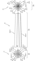
- FIG. 2 shows an ion guide configuration including 12 cylindrical rod electrodes.
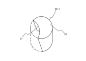
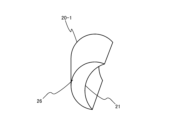
- FIG. 1 is a diagram (part 1) showing only one rod electrode among the rod electrodes that constitute an ion guide.
- FIG. 2 is a diagram (part 2) showing only one rod electrode among the rod electrodes that constitute the ion guide.
- 1A to 1C are a top view, a cross-sectional view, and an arrow view of one of the rod electrodes according to the present embodiment.
- FIG. 2 is a perspective view showing four of the twelve rod electrodes that make up the ion guide.
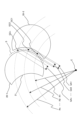
- FIG. 11 is a diagram relating to the gap between adjacent rod electrodes.
- FIG. 1 is a diagram showing the configuration of a mass spectrometer used in the first embodiment.
- FIG. 2 shows an ion guide configuration including 12 cylindrical rod electrodes.
- FIG. 1 is a diagram (part 1) showing only one rod electrode among the rod
- FIG. 1 is a diagram (part 1) showing an example of an ion guide provided with a holder.
- FIG. 2 is a diagram (part 2) showing an example of an ion guide provided with a holder.
- FIG. 13 is a diagram showing another explanation of the features of the ion guide according to the first embodiment.
- FIG. 13 shows an ion guide according to a second embodiment.
- FIG. 13 is a diagram showing an ion guide according to a third embodiment.
- FIG. 13 is a diagram showing a first modified ion guide.
- FIG. 3 is a diagram (part 3) showing only one rod electrode among the rod electrodes that constitute the ion guide.
- FIG. 4 is a diagram (part 4) showing only one rod electrode among the rod electrodes that make up the ion guide.
- FIG. 3 is a diagram (part 3) showing only one rod electrode among the rod electrodes that constitute the ion guide.
- FIG. 4 is a diagram (part 4) showing only one rod electrode among the
- FIG. 13 shows an ion guide according to a second modified example.
- FIG. 5 is a diagram (part 5) showing only one rod electrode among the rod electrodes that make up the ion guide.
- FIG. 6 is a diagram (part 6) showing only one rod electrode among the rod electrodes that make up the ion guide.
- FIG. 13 shows an ion guide according to a third modified example.
- FIG. 7 is a diagram showing only one rod electrode among the rod electrodes that make up the ion guide.
- FIG. 8 is a diagram showing only one rod electrode among the rod electrodes that make up the ion guide.
- FIG. 13 is a diagram showing the configuration of an ion guide according to a fourth embodiment.
- FIG. 5 is a diagram (part 5) showing only one rod electrode among the rod electrodes that make up the ion guide.
- FIG. 6 is a diagram (part 6) showing only one rod electrode among the rod electrodes that make up the ion guide.
- FIG. 13 shows an i
- FIG. 9 is a diagram showing only one rod electrode among the rod electrodes that make up the ion guide.
- FIG. 10 is a diagram showing only one rod electrode among the rod electrodes that make up the ion guide.
- FIG. 2 is a perspective view showing two of the four rod electrodes that constitute the ion guide.
- FIG. 13 is a diagram showing the configuration of a dodecapole ion guide in which twelve cylindrical rod electrodes are arranged in parallel according to a fifth embodiment.
- FIG. 3 is a diagram (part 3) showing an example of an ion guide provided with a holder.
- FIG. 13 is a cross-sectional view showing an ion guide according to a sixth embodiment.
- FIG. 1 illustrates common features.
- FIG. 1 illustrates common features.
- FIG. 2 is a partial enlarged view of a rod electrode that constitutes an ion guide.
- FIG. 1 is a diagram (part 1) showing the configuration of an ion guide according to a comparative example.
- FIG. 4 is a diagram showing the configuration of an ion guide provided with a holder.
- FIG. 2 is a diagram (part 2) showing the configuration of an ion guide according to a comparative example.
- FIG. 5 is a diagram showing the configuration of an ion guide provided with a holder.
- a 12-pole ion guide 200 composed of 12 rod electrodes 20 (see FIG. 2 ) having a notch 21 that is a recess having a concave and arcuate shape is used in the mass spectrometer 1.
- FIG. 1 is a diagram showing the configuration of a mass spectrometer 1 used in the first embodiment.
- the mass spectrometer 1 mainly comprises an ion source 100, an ion guide 200, an ion transport device 300, and a mass analysis section 400.
- the ion guide 200, the ion transport device 300, and the mass analysis section 400 are provided inside a vacuum vessel 130.
- the dashed lines indicate voltage control lines, and the dashed lines indicate control lines through which information is transmitted.
- the ion source 100 is mainly composed of an ion generator 110, an ion source chamber 120, etc.
- the ion source 100 can use various ionization methods such as electrospray (ESI), atmospheric pressure chemical ionization (APCI), and atmospheric pressure photoionization (APPI).
- ESI electrospray
- APCI atmospheric pressure chemical ionization
- APPI atmospheric pressure photoionization
- the ion generator 110 generates ions from the introduced sample solution Q and sprays the generated ions into the ion source chamber 120.
- the inside of the ion source chamber 120 is evacuated (symbol E) to remove unnecessary droplets.
- electrostatic spraying and gas spraying in the ion generator 110 are used in combination to reduce unnecessary droplets. This promotes vaporization of the sample solution Q and improves ionization efficiency.
- electrostatic spraying is performed by applying a high voltage to the ion generator 110 by the power supply 500.
- the flow rate of the sprayed gas is about 0.5 to 10 L/min.
- inert gases such as nitrogen and argon are used as the gas used in the ion generator 110.
- the flow rate of the sample solution Q is generally in the range of about nL (nanoliter)/min to mL (milliliter)/min.
- a heating gas up to about 800°C.
- the flow rate of the heating gas is about 0.5 to 50 L/min, and an inert gas such as nitrogen or argon is generally used.
- a counter electrode 121 having a hole H1 is arranged in front of the introduction electrode 122.
- Gas G is introduced from the hole H11 into the space between the introduction electrode 122 and the counter electrode 121. This allows gas G to be introduced between the introduction electrode 122 and the counter electrode 121. As a result, noise components such as excess droplets sprayed by the ion source 100 can be prevented from being introduced into the hole H2 of the introduction electrode 122.
- the flow rate of gas G is about 0.5 to 50 L/min, and an inert gas such as nitrogen or argon is generally used. Note that a voltage is also applied to the counter electrode 121 and the introduction electrode 122 by the power source 500, but the control lines for the voltage applied to the counter electrode 121 and the introduction electrode 122 are omitted in FIG. 1.
- Ions introduced into the ion source chamber 120 are introduced into hole H2 in the introduction electrode 122 via hole H1 in the counter electrode 121. At this time, the ions move in the direction of ion generation device 110 ⁇ ion source chamber 120 ⁇ hole H1 ⁇ hole H2 due to the electric field generated between the ion generation device 110 and the introduction electrode 122.
- the diameters of hole H1 in the counter electrode 121 and hole H2 in the introduction electrode 122 are generally several mm or less, and the voltage applied to the counter electrode 121 is generally a maximum of ⁇ several kV.
- the polarity of the voltages applied to the counter electrode 121 and the introduction electrode 122 is the same.
- the ions are introduced from hole H2 in the introduction electrode 122 through the ion guide 200 and ion transport device 300 into the mass analysis section 400, where they are analyzed.
- Various voltages are applied to the ion source 100 (ion generation device 110), ion guide 200, ion transport device 300, and mass analysis section 400 by the power supply 500.
- the timing and voltage value of the voltage application by the power supply 500 are controlled by the control device 600.
- the inside of the vacuum vessel 130 may be divided into a plurality of vacuum chambers V1 to V3.
- the vacuum chambers V1 and V2 are electrically connected to each other through a small-diameter hole H3.
- the vacuum chambers V2 and V3 are electrically connected to each other through a small-diameter hole H4.
- the holes H2, H3, and H4 provided in the introduction electrode 122 are paths for ions.
- a voltage may be applied to the member having the holes H3 and H4.
- the housing part such as the vacuum vessel 130 and the member having the holes H3 and H4 (and the hole H2) are insulated via an insulator (not shown) or the like.
- the holes H3 and H4 are generally several mm or less in size.
- the vacuum chambers V1 to V3 are evacuated by vacuum pumps P1 to P3, respectively. As a result, the vacuum chamber V1 is generally maintained at several hundred to several thousand Pa, the vacuum chamber V2 at several Pa, and the vacuum chamber V3 at 0.1 Pa or less.
- the vacuum chamber V1 is provided with an ion guide 200 that transmits ions while converging them.
- the vacuum chamber V2 is provided with an ion transport device 300 that transmits ions while converging them in the same manner as the ion guide 200.
- the ion transport device 300 may be provided with a multipole ion guide 200, an electrostatic lens, an ion funnel, or the like.
- a high-frequency voltage, a direct current voltage, an alternating current voltage, or a combination of these voltages is applied to the ion guide 200 and the ion transport device 300 from the power source 500.
- the number of vacuum chambers V1 to V3 may be greater or less than the number shown in FIG. 1.
- another vacuum chamber maintained at several hundred Pa may be provided between vacuum chamber V1 and vacuum chamber V2, and an ion transport device 300 other than the ion transport device 300 shown in FIG. 1 may be disposed in this vacuum chamber.
- the mass spectrometry section 400 is composed of an ion separator 401, a detector 402, etc.
- the ion separator 401 which separates and dissociates ions, includes an ion trap, a quadrupole filter electrode, a collision cell, a time-of-flight mass analyzer, etc.
- the ions passing through the ion separator 401 are detected by a detector 402.
- the detector 402 may be an electron multiplier or a multichannel detector.
- the ions detected by the detector 402 are converted into an electric signal, and the mass, intensity, and other information of the ions can be analyzed in detail by the controller 600.
- the device 600 includes an input/output unit (not shown) and a memory for receiving instructions from a user and controlling voltage, etc., and also includes software and the like required for operating the power supply 500.
- the voltage supplied to the mass analysis section 400 may be a high-frequency voltage, a direct current voltage, an alternating current voltage, or a combination of these voltages.
- the longitudinal direction of the ion guide 200 is defined as the X-axis, and the axes that are perpendicular to the X-axis, pass through the center C of the ion guide 200, and are perpendicular to each other are defined as the Y-axis and Z-axis.
- the direction from the ion source 100 to the mass analysis unit 400 is defined as the X-axis
- the direction perpendicular to the X-axis and upwards of the mass spectrometer 1 is defined as the Z-axis
- the direction perpendicular to the X-axis and Z-axis is defined as the Y-axis.
- FIGS. 2 is a diagram showing the configuration of an ion guide 200 equipped with twelve (12-pole) cylindrical rod electrodes 20 (20-1 to 20-12).
- an ion guide 200 having n rod electrodes 20 will be referred to as an n-pole ion guide 200.
- the left diagram Z1 is a view seen from the ion inlet side.
- the ion inlet side (or simply the inlet side) is the side of the ion source 100 shown in FIG. 1.
- FIG. 2 is a view seen from the side of the ion guide 200.
- the right diagram Z3 in FIG. 2 is a view seen from the ion outlet side (the right side in FIG. 1).
- the ion outlet side (or simply the outlet side) is the side of the mass analysis section 400 shown in FIG. 1.
- a plurality of rod electrodes 20 (20-1 to 20-12) having a columnar shape are arranged in a circle (annularly) with respect to the center C of the ion guide 200.
- Each rod electrode 20 is arranged to have an angle " ⁇ " in the longitudinal direction. The angle " ⁇ " will be described later.
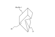
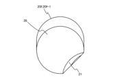
- FIGS. 3A and 3B are diagrams showing only one of the rod electrodes 20 (20-1) that constitute the ion guide 200 shown in FIG. 2.
- FIG. 3A is a diagram showing the rod electrode 20 from the ion inlet side
- FIG. 3B is a diagram showing the rod electrode 20 from the ion outlet side.
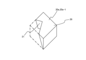
- the rod electrode 20 according to this embodiment is characterized in that the cylindrical rod electrode 20 has a notch 21 on its side, which is a concave, arc-shaped recess.
- a protrusion 26 is provided on the side of the rod electrode 20 opposite to the side on which the notch 21 is provided.
- the notch 21 (recess) and the protrusion 26 are provided on the side of the rod electrode 20.
- the shape without the notch 21 is shown by a dashed line.
- This embodiment is characterized in that the rod electrodes 20-1 to 20-12 having the notch 21 are arranged at an angle " ⁇ " with respect to the X-axis as shown in Figure 2. That is, the ion guide 200 according to this embodiment is configured so that the mass spectrometer 1 side (exit side) is narrowed.
- " ⁇ " is preferably about 10° or less.
- the reference numerals for the notch 21 and the protrusion 26 are omitted to avoid complication.
- the notch 21 of one rod electrode 20 and the protrusion 26 of another rod electrode 20 are fitted together in a non-contact state.
- Fig. 4 shows a top view, a cross-sectional view, and an arrow view of one of the rod electrodes 20 according to this embodiment.
- the upper drawing Z4 of Fig. 4 is a view (top view) of the rod electrode 20 seen from above.
- the lower right drawing Z5 of Fig. 4 is an A-A cross-sectional view of the rod electrode 20.
- the lower left drawing Z6 of Fig. 4 is a view (B arrow view) of the rod electrode 20 seen from the arrow B (inclined direction of ⁇ °) of the ion guide 200.
- FIG. 4 shows a top view, a cross-sectional view, and an arrow view of one of the rod electrodes 20 according to this embodiment.
- the rod electrode 20 is characterized in that a concave cutout 21 is formed in an arc of radius "RC" over the entire length of a cylinder with a diameter ( ⁇ ) "D” and a length "L".
- the cutout 21 is formed in a state of being inclined at a predetermined angle " ⁇ °" with respect to the longitudinal direction of the rod electrode 20 (provided with a predetermined angle).
- the cutout 21 is shallow on the entrance side and deep on the exit side. In this way, the thickness of the rod electrode 20 can be changed on the entrance side and the exit side. Even if the twelve rod electrodes 20 are arranged inclined at an angle " ⁇ " with respect to the X-axis as shown in FIG.
- the ion guide 200 can be assembled without the rod electrodes 20 coming into contact with each other. In other words, even if the rod electrodes 20 are arranged in an inclined manner, the cutout 21 of one rod electrode 20 and the protrusion 26 of another rod electrode can be kept in a non-contact engagement state. It is desirable that "D” be approximately 10 mm or less, “L” be approximately 100 to 300 mm, and " ⁇ °” be approximately 5° or less.
- the notch 21 is formed in an arc of a constant radius "RC" over the entire length of the rod electrode 20.
- RC constant radius
- the shape of the notch 21 is not important, and as will be described later, the shape of the notch 21 does not need to be the same over the entire length.
- the ridge portion 22 resulting from the formation of the notch 21 may be chamfered or arc-chamfered for the purpose of preventing discharge, etc.
- the size of the gap between adjacent rod electrodes 20 depends on the applied voltage value, but is preferably about 0.1 mm to 5 mm.
- the width of the gap may be configured to be approximately the same from the entrance side to the exit side. Alternatively, the size of the gap may change from the entrance side to the exit side. This also applies to the embodiments and modified examples shown below.
- FIG. 5 is a perspective view showing four rod electrodes 20-6 to 20-9 out of the twelve rod electrodes 20 that constitute the ion guide 200.
- the characteristics of the rod electrodes 20 shown in FIGS. 2 to 4 realize an ion guide 200 in which the radius of the inscribed circle gradually decreases from the inscribed circle 23 of the rod electrode 20 on the entrance side to the inscribed circle 24 of the rod electrode 20 on the exit side.
- the rod electrodes 20 are arranged at an angle of " ⁇ " (see FIG. 2) so that the inscribed circle 23 of the rod electrode 20 on the entrance side is larger than the inscribed circle 24 of the rod electrode 20 on the exit side. This makes it possible to gradually narrow the internal space of the ion guide 200 toward the exit side.
- the focusing force of the multipole electric field can be gradually strengthened toward the exit side, and ions can be gradually focused near the center C.
- FIG. 6 is a diagram relating to the gap between adjacent rod electrodes 20.
- the dashed line S connects the centers GC1 to GCn of the rod gaps GA1 to GAn at the same distances "R1" to "Rn" (the respective arcs shown by the dashed lines in Fig. 6) from the center C of the ion guide 200.
- the ion guide 200 according to this embodiment is characterized in that the dashed line S is not a straight line. This relationship may exist over the entire length of each rod electrode 20, or may exist in a part of the rod electrode 20 in the longitudinal direction.
- FIG. 7 and 8 show examples of an ion guide 200 provided with a holder 210.
- FIG. The left diagram Z11 in Fig. 7 is a diagram of the ion guide 200 provided with the holder 210, as viewed from the inlet side.
- the right diagram Z12 in Fig. 7 is a side view of the ion guide 200 provided with the holder 210.
- Fig. 8 is an enlarged view of the rod electrodes 20-1 to 20-2.
- the same reference numerals are used for the same configurations as Figs. 2 to 6, and the description thereof will be omitted.
- the actual ion guide 200 as shown in FIG.
- the twelve rod electrodes 20 (20-1 to 20-12) are held by holders 210 (210a, 210b) made of an insulating material, that is, made of an insulating material.
- the holders 210 (210a, 210b) have a shape that contacts each of the rod electrodes 20 and are made of an insulating material.
- the holders 210 may have any shape as long as they can support the rod electrodes 20.
- each of the rod electrodes 20-1 to 20-12 is arranged at an incline with respect to the X-axis. Therefore, the inner diameters of the holders 210a and 210b made of an insulating material are different.
- the inner diameter of the holder 210a arranged on the entrance side is larger than the inner diameter of the holder 210b arranged on the exit side.
- the rod electrodes 20-1 to 20-12 having the concave cutouts 21 are arranged in a tilted state with respect to the X-axis.
- the contact parts 211a and 211b are parts where the holder 210 (210a, 210) and the rod electrode 20 are in contact.
- the contact part 211a is the part where the holder 210a is in contact with the rod electrode 20.
- the contact part 211b is the part where the holder 210b is in contact with the rod electrode 20.
- the holder 210 holds each rod electrode 20, allowing the ion guide 200 to be installed in the vacuum chamber V1 (see Figure 1) without each rod electrode 20 becoming dispersed.
- the insulating surface portions 212a and 212b are not visible.
- the insulating surface portion 212a is the portion of the contact portion 211a that corresponds to the gap of the rod electrode 20.
- the insulating surface portion 212b is the portion of the contact portion 211b that corresponds to the gap of the rod electrode 20.
- FIG. 9 is a diagram showing another explanation of the features of the ion guide 200 according to the first embodiment.
- rod electrodes 20-1 to 20-2 are shown in Fig. 9.
- a center GC of the rod gap GA at a certain distance "R" (a circular arc shown by a dashed line in Fig. 9) from the center C of the ion guide 200 (see Fig. 2) and a line GL connecting the centers C are defined.
- This embodiment is characterized in that the shapes of adjacent rod electrodes 20 (rod electrodes 20-1 and 20-2 in the example shown in Fig. 9) are asymmetrical with respect to the line GL in the vicinity of the line GL. This relationship may exist over the entire length of the rod electrode 20, or may exist in a part of the longitudinal direction.
- the notch 21 of one rod electrode 20 and the protrusion 26 of another rod electrode 20 are fitted together in a non-contact state.
- droplets discharged from the inside of the ion guide 200 to the outside are blocked by the protrusion 26 of the rod electrode 20. This makes it difficult for the droplets to reach the insulating surface portion 212a.
- the configuration of the ion guide 200 according to this embodiment described above can prevent the insulating surface portions 212a and 212b of the holder 210 from being contaminated by liquid droplets. This can improve the robustness of the ion guide 200. Furthermore, by improving the robustness of the ion guide 200, the diameter of the holes H1 and H2 (see FIG. 1) can be increased to increase the amount of ions introduced. This can improve the analytical sensitivity of the mass spectrometer 1 (see FIG. 1).
- the ion guide 200 according to this embodiment can also be placed in other vacuum chambers, such as vacuum chamber V2, in addition to vacuum chamber V1 shown in FIG. 1.
- FIG. 10 shows an ion guide 200a according to the second embodiment.
- Fig. 10 for simplicity, only the differences from the ion guide 200 shown in Figs. 2 to 9 are explained.
- the rod electrode 20a is shown for simplicity.
- the left diagram Z21 in Fig. 10 is a view from the ion inlet direction.
- the center diagram Z22 in Fig. 10 is a view from the side. In the center diagram Z22 in Fig. 10, for simplicity, only the rod electrodes 20a-1 and 20a-5 are shown.
- FIG. 10 is a view from the ion outlet side.
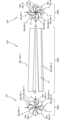
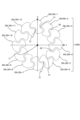
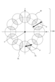
- FIG. 10 shows an ion guide 200a in which eight (octapole) cylindrical rod electrodes 20a having concave and arcuate cutouts 21 are arranged in a circle around the center C.
- the structure of each rod electrode 20a is the same as that of the rod electrode 20 shown in the first embodiment.
- the cutout 21 of one rod electrode 20a and the convex portion 26 of another rod electrode 20a are engaged in a non-contact state. That is, the ion guide 200a shown in FIG. 10 is different from the ion guide 200 shown in FIG. 2 to FIG. 9 in that it is provided with eight cylindrical rod electrodes 20a-1 to 20a-8 (octapole).
- the basic effect of the ion guide 200a shown in FIG. 10 is the same as that of the example shown in FIG. 2 to FIG. 9, but the ion focusing efficiency of the octapole tends to be higher than that of the dodecapole.
- FIG. 11 is a diagram showing an ion guide 200b according to the third embodiment.
- the left diagram Z31 in Figure 11 is a view from the ion inlet side.
- the center diagram Z32 in Figure 11 is a view from the side. Note that, for simplicity, only the rod electrodes 20b-1 and 20b-4 are shown in the center diagram Z32 in Figure 11.
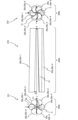
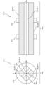
- FIG. 11 shows an ion guide 200b in which six (hexapole) cylindrical rod electrodes 20b having concave and arcuate cutouts 21 are arranged in a circle around the center C.
- the structure of each rod electrode 20b is the same as that of the rod electrode 20 shown in the first embodiment.
- the cutout 21 of one rod electrode 20b is engaged with the convex portion 26 of another rod electrode 20b in a non-contact state. That is, the ion guide 200b shown in FIG. 11 is different from the ion guide 200 shown in FIG. 2 to FIG.
- ion guide 200b in that it includes six cylindrical rod electrodes 20b-1 to 20b-6 (hexapole).
- the basic effect of the ion guide 200b is the same as that of the ion guide 200 shown in FIG. 2 to FIG. 9 and the ion guide 200a shown in FIG. 10, but the ion focusing efficiency of the hexapole tends to be higher than that of the octapole.
- FIG. 12 is a diagram showing a first modified ion guide 200c.
- Fig. 12 for the sake of simplicity, only the differences from the ion guide 200 shown in Figs. 2 to 9 will be described. Also, for the sake of simplicity, only the rod electrode 20c is shown in Fig. 12.
- the left diagram Z41 in Fig. 12 is a view from the ion inlet side direction (the left side of Fig. 1). Also, the center diagram Z42 in Fig. 12 is a view from the side.
- An ion guide 200c shown in FIG. 12 has twelve rod electrodes 20c (20c-1 to 20c-12) each having a substantially oval cylindrical shape (cross-sectional shape being substantially oval) arranged in a circle with respect to the center C.
- Fig. 13A and Fig. 13B are diagrams showing only one rod electrode 20c-1 among the rod electrodes 20c constituting the ion guide 200c.
- Fig. 13A is a diagram showing the rod electrode 20c-1 as seen from the entrance side
- Fig. 13B is a diagram showing the rod electrode 20c-1 as seen from the exit side.
- the rod electrode 20c of the first modification is characterized in that a concave and arc-shaped notch 21 is provided in the substantially elongated cylindrical rod electrode 20c (rod electrode 20c-1 in Figs. 13A and 13B).
- a convex portion 26 is provided on the side opposite to the side of the rod electrode 20c on which the notch 21 is provided.
- the shape of the rod electrode 20c without the notch 21 is shown by a dashed line.
- the basic effect of the ion guide 200c according to the first modification is the same as that of the ion guide 200 shown in Figs. 2 to 9.
- the reference numerals for the notch 21 and the protrusion 26 are omitted to avoid complication. As shown in FIG. 12, the notch 21 of one rod electrode 20c and the protrusion 26 of another rod electrode 20c are fitted together in a non-contact state.
- FIG. 14 is a diagram showing a second modified ion guide 200d.
- the left diagram Z51 in Fig. 14 is a view from the ion inlet side.
- the center diagram Z52 in Fig. 14 is a view from the side.
- the right diagram Z53 in Fig. 14 is a view from the ion outlet side. 14 shows the configuration of a 12-pole ion guide 200d that is composed of cylindrical rod electrodes 20d (20d-1 to 20d-12). For simplicity, only the rod electrodes 20d are shown in FIG.
- FIGS. 15A and 15B are diagrams showing only one rod electrode 20d-1 of the rod electrodes 20d that constitute the ion guide 200d.
- Fig. 15A is a diagram showing the rod electrode 20d-1 as viewed from the entrance side.
- Fig. 15B is a diagram showing the rod electrode 20d-1 as viewed from the exit side.
- each rod electrode 20d is arranged in a circle with respect to the center C.
- the rod electrode 20d of the second modification shown in Figs. 14 to 15B (rod electrode 20d-1 in Figs. 15A and 15B) is characterized in that a concave V-shaped notch 21 is provided in the cylindrical rod electrode 20d.
- a convex portion 26 is provided on the side opposite to the side of the rod electrode 20d on which the notch 21 is provided.
- the shape of the rod electrode 20d without the notch 21 is shown by a dashed line.
- the basic effect of the ion guide 200d is similar to that of the ion guide 200 shown in Figs. 2 to 9.
- the reference numerals for the notch 21 and the protrusion 26 are omitted to avoid complication. As shown in FIG. 14, the notch 21 of one rod electrode 20d and the protrusion 26 of another rod electrode 20d are fitted together in a non-contact state.
- FIG. 16 is a diagram showing a third modified ion guide 200e.
- the left diagram Z61 in Fig. 16 is a diagram seen from the ion inlet side.
- the center diagram Z62 in Fig. 16 is a diagram seen from the side of the ion guide 200e.
- FIG. 16 shows a dodecapole ion guide 200e that is composed of twelve rectangular rod electrodes 20e (20e-1 to 20e-12).
- FIG. 17A and 17B are diagrams showing only one rod electrode 20e-1 among the rod electrodes 20e that constitute the ion guide 200e.
- Fig. 17A is a diagram showing the rod electrode 20e-1 as viewed from the entrance side
- Fig. 17B is a diagram showing the rod electrode 20e-1 as viewed from the exit side.
- each rod electrode 20e is arranged in a circle with respect to the center C.
- the rod electrode 20e of the third modification shown in Figs. 16 to 17B (rod electrode 20e-1 in Figs. 17A and 17B) is characterized in that a concave V-shaped notch 21 is provided in the rod electrode 20e having a rectangular column shape.
- a convex portion 26 is provided on the side opposite to the side of the rod electrode 20e on which the notch 21 is provided.
- the shape of the rod electrode 20e without the notch 21 is shown by a dashed line.
- the basic effect of the ion guide 200e is similar to that of the ion guide 200 shown in Figs. 2 to 9.
- the reference numerals for the notch 21 and the protrusion 26 are omitted to avoid complication. As shown in FIG. 16, the notch 21 of one rod electrode 20e and the protrusion 26 of another rod electrode 20e are fitted together in a non-contact state.
- FIG. 18 is a diagram showing the configuration of an ion guide 200f according to the fourth embodiment.
- FIG. 18 for simplicity, only the differences from the ion guide 200 shown in FIG. 2 to FIG. 9 are described. Also, for simplicity, only the rod electrodes 20f are shown in FIG. 18.
- the left diagram Z71 in FIG. 18 is a view of the ion guide 200f from the ion inlet side.
- the center diagram Z72 in FIG. 18 is a view of the ion guide 200f from the side. Note that, for simplicity, only the rod electrodes 20f-1 and 20f-3 are shown in the center diagram Z72 in FIG. 18.
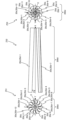
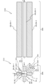
- the right diagram Z73 is a view of the ion guide 200f from the ion outlet side. 18 shows the configuration of a quadrupole ion guide 200f in which four cylindrical rod electrodes 20f (20f-1 to 20f-4) are arranged in a circle about a center C. As shown in FIG. 18, in the ion guide 200f, a concave-shaped and arc-shaped notch 21 is provided in the rod electrode 20f from the middle of the longitudinal direction.
- FIGS. 19A and 19B are diagrams showing only one rod electrode 20f-1 out of the rod electrodes 20f that make up the ion guide 200f.
- FIG. 19A is a diagram showing the rod electrode 20f-1 from the entrance side.
- FIG. 19B is a diagram showing the rod electrode 20f-1 from the exit side.
- the rod electrode 20f of the fourth embodiment (rod electrode 20f-1 in the example shown in FIGS. 19A and 19B) is characterized in that a concave and arc-shaped notch 21 is provided in the rod electrode 20f from midway along the longitudinal direction.
- a convex portion 26 is provided on the side of the rod electrode 20f opposite to the side on which the notch 21 is provided.
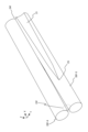
- FIG. 20 is a perspective view showing two rod electrodes 20f-3 and 20f-4 out of the four rod electrodes 20f that constitute the ion guide 200f. 2 to 9, the radius of the inscribed circle gradually decreases from the inscribed circle 23f of the rod electrode 20f on the entrance side to the inscribed circle 24f of the rod electrode 20f on the exit side.
- the notch 21 is provided from a starting point 25 provided midway along the longitudinal direction of the rod electrode 20f toward the exit side. That is, in the rod electrode 20f, the notch 21 is provided from the midway along the rod electrode 20f toward the ion exit side (the direction of the inscribed circle 24f) with respect to the longitudinal direction of the rod electrode 20f.
- the reference numerals for the notch 21 and the protrusion 26 are omitted to avoid complication.
- the notch 21 of one rod electrode 20f and the protrusion 26 of another rod electrode 20f are fitted together in a non-contact state.
- the holder 210 (see FIG. 7) is not installed in the portion where the notch 21 is not provided. Therefore, contamination of the insulating surface portions 212a and 212b does not occur in the portion where the notch 21 is not provided.
- the basic effect of the ion guide 200f is the same as that of the ion guide 200, but the quadrupole tends to have a higher ion focusing efficiency than the hexapole of the third embodiment.
- the number of rod electrodes 20f number of quadrupoles
- the amount of cutting required for the notch 21 can be reduced compared to the ion guides 200, 200a to 200e. This allows for cost reduction.
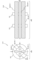
- FIG. 21 is a diagram showing the configuration of a 12-pole ion guide 200g in which 12 cylindrical rod electrodes 20g (20g-1 to 20g-12) are arranged parallel to the longitudinal direction.
- the left diagram Z81 shows the ion guide 200g from the ion inlet side.
- the center diagram Z82 of FIG. 21 only the rod electrodes 20g-1 and 20g-7 are shown for simplicity.
- the center diagram Z82 of FIG. 21 shows the ion guide 200g from the side.
- the right diagram Z83 of FIG. 21 shows the ion guide 200g from the ion outlet side.
- cylindrical rod electrodes 20g-1 to 20g-12 each having a concave and arcuate cutout 21 are arranged in parallel. Therefore, the left diagram Z81 and the right diagram Z83 in Fig. 21 show a state in which the electrodes are simply inverted with respect to the Z axis.
- the rod electrodes 20g are arranged in a circle with respect to the center C.
- a protrusion 26 is provided on the side of the rod electrode 20g opposite to the side on which the notch 21 is provided.
- the notch 21 of one rod electrode 20g and the protrusion 26 of another rod electrode 20g are fitted together in a non-contact state.
- the features of the ion guide 200g shown in the fifth embodiment are the same as those of the ion guide 200.
- the feature shown in FIG. 6 is that the dashed dotted line S connecting the centers GC1 to GCn of the rod gaps GA1 to GAn at the same distances R1 to Rn from the center C is not a straight line.
- a line GL is defined connecting the center GC of the rod gap GA at a predetermined distance "R" from the center C of the ion guide 200g to the center C.
- the feature shown in FIG. 9 is that the shape of the rod electrode 20g is asymmetrical with respect to the line GL in the vicinity of the line GL.
- FIG. 22 shows an example of an ion guide 200g provided with a holder 210c.
- a left diagram Z91 in Fig. 22 is a diagram of the ion guide 200g provided with the holder 210c, as viewed from the inlet side.
- a right diagram Z92 in Fig. 22 is a side view of the ion guide 200g provided with the holder 210c.
- an actual ion guide 200g may have an insulating holder 210c to hold the 12 rod electrodes 20g (20g-1 to 20g-12).
- the rod electrodes 20g (20g-1 to 20g-12) are arranged parallel to the X-axis, so that the holders 210c on the entrance side and the exit side may have the same shape as shown in FIG.
- the ion guide 200g has the same effect as the ion guide 200 shown in Figures 2 to 9. In addition, since the rod electrode 20g is not installed at an angle, the ion guide 200g can be installed more easily than the ion guides 200, 200a to 200f.
- FIG. 23 is a cross-sectional view showing an ion guide 200h according to the sixth embodiment.
- FIG. 23 for simplicity, only the differences from ion guide 200 are described.
- a configuration has been shown in which the notch 21 is provided on one of the rod electrodes 20, 20a to 20g in the vicinity of the gap formed between the adjacent rod electrodes 20, 20a to 20g. That is, in the examples so far, the notch 21 is provided only on one side surface of the rod electrodes 20, 20a to 20g.
- the ion guide 200h shown in the sixth embodiment is composed of rod electrodes 20h (20h-1 to 20h-12).
- the rod electrodes 20h are provided with concave and arc-shaped notches 21 on the side surfaces of both rod electrodes 20h in the vicinity of the gap formed between the adjacent rod electrodes 20h.
- the ion guide 200h is composed of 12 (12-pole) cylindrical rod electrodes 20h. That is, in the sixth embodiment, the notch 21 is provided on both side surfaces of each of the rod electrodes 20h constituting the ion guide 200h. In addition, when the notch 21 is provided on both sides, this means that the notch 21 and the protrusion 26 are provided on one side of the rod electrode 20h, and the notch 21 and the protrusion 26 are also provided on the other side.
- FIG. 23 is a cross-sectional view of the ion guide 200h in the YZ plane (see FIG. 1 and FIG. 5).
- arc-shaped cutouts 21 are provided in the rod electrodes 20h located on both sides of the gaps in the rod electrodes 20h.
- the cutouts 21 and the protrusions 26 are provided on both side surfaces of the rod electrodes 20h. The cutouts 21 of one rod electrode 20h and the protrusions 26 of another rod electrode 20h are fitted together in a non-contact state.
- the ion guides 200, 200a to 200h of each example can achieve the above-mentioned effects even when the characteristic elements of each of the ion guides 200, 200a to 200h are combined.
- the ion guide 200 represents the ion guides 200 and 200 to 200h
- the rod electrode 20 represents the rod electrodes 20 and 20a to 20h.
- ion capture efficiency higher when the number of quadrupoles is larger
- ion convergence efficiency higher when the number of quadrupoles is smaller.
- the optimal configuration of the ion guide 200 may differ depending on the target sample, the configuration of any number of quadrupoles is very important.
- the configuration of the ion guide 200 may be configured with a number of rods other than the quadrupole, hexapole, octapole, and dodecapole shown in the above examples.
- the number of rod electrodes 20 is limited to an even number. This is because voltages of opposite phases are applied to adjacent rod electrodes 20.
- the ion guide 200 which is composed of multiple rod electrodes 20, can be implemented, for example, by screwing the insulator holder 210 and the rod electrodes 20 together. Other fixing means such as gluing the holder 210 and the rod electrodes 20 together may also be used. Parts such as pins that determine the positional relationship between the holder 210 and the rod electrodes 20 may also be used.
- the rod electrode 20 may have a shape other than the cylinder, rectangular column, or approximately elongated cylinder shown in the above examples (e.g., a hexagonal column, etc.).
- various methods can be used to machine the cutout portion 21. For example, cutting (including machining using a multi-axis machining center, etc.), electric discharge machining (including wire-cut electric discharge machining, etc.), casting, a three-dimensional printer, plastic molding (adding a metal layer to the surface), etc.
- FIG. 24 is a diagram showing a feature common to the examples described so far (particularly the cylindrical rod electrode 20).
- the diameter of the rod electrode 20 (the maximum diameter in the direction where the notch 21 (see FIG. 3A and FIG. 3B, etc.) is not provided) is defined as "D", and the center-to-center distance between adjacent rod electrodes 20 is defined as "P".
- the ion guide 200 is characterized by the relationship D>P. That is, since "D" is larger than "P", as shown in FIG. 24, there is an overlapping portion (shaded portion DL) of each rod electrode 20.
- the overlapping portion (shaded portion DL) is used as the notch 21, and a gap is provided between each rod electrode 20, which is a feature of this embodiment. This relationship may be held over the entire length of the rod electrode 20, or may be held in a part of the longitudinal direction as shown in FIG. 18 to FIG. 20.
- FIG. 25 is a partial enlarged view of the rod electrodes 20-1 and 20-2 out of the rod electrodes 20 that constitute the ion guide 200. As shown in FIG. In the ion guide 200 of this embodiment, the notch 21 of one rod electrode 20 and the protrusion 26 of another rod electrode 20 are fitted together in a non-contact state.
- a configuration in which the contact portion 211a and the insulating creeping surface portion 212a are not visible from the center C can be realized.
- the angle between each of the straight lines L1 and L2 connecting the center C and both ends of the range of the insulating creeping surface portion 212a is defined as " ⁇ ".
- An obstacle i.e., the rod electrode 20-1 exists within the range of " ⁇ ". Therefore, the feature of this embodiment is that the insulating creeping surface portion 212a is not visible from the center C.
- the insulating surface portions 212a, 212b are not visible when the ion guide 200 is viewed from the inlet side.
- FIG. 26 is a diagram showing the configuration of an ion guide 200j according to a comparative example.
- the left diagram Z101 in Fig. 26 shows the ion guide 200j from the ion inlet side, and the right diagram Z102 shows a cross-sectional view of the ion guide 200j on the Z axis.
- FIG. 26 shows a multipole (quadrupole in the example shown in FIG. 26) ion guide 200j that is composed of cylindrical rod electrodes 20j (20j-1 to 20j-4).
- FIG. 27 is a diagram showing the configuration of an ion guide 200j provided with a holder 210.
- the left diagram Z111 in Fig. 27 shows the ion guide 200j as seen from the ion inlet side, and the right diagram Z112 shows a cross-sectional view of the ion guide 200j on the Z axis.
- a line SA is defined as connecting the centers GC1 to GCn of rod gaps GA1 to GAn at the same distance "R1" to "Rn" (the circle shown by the dashed line in FIG. 26) from the center C of ion guide 200j.
- the characteristic of ion guide 200j with multipoles as shown in FIG. 26 is that line SA is a straight line.
- the rod electrodes 20j are arranged in parallel along the X-axis direction. Therefore, the relationship that the line SA connecting the centers GC1 to GCn of the rod gaps GA1 to GAn is a straight line is constant over the longitudinal direction of the rod electrodes 20j.
- the insulating surface portion 212 of the holder 103 is visible. Ions and droplets generated by the ion source 100 (see FIG. 1) are introduced into the ion guide 200j.
- the ion guide 200j has the role of discharging droplets that become a noise factor during analysis from the rod gaps GA1 to GAn (see FIG. 26) and the like, and converging only ions near the center C by the multipole electric field. In other words, the ion guide 200j has the role of separating the airflow containing the droplets from the ions.
- the insulating surface portion 212 of the holder 210 is more likely to be contaminated by liquid droplets.
- the insulating surface portion 212 which is intended to insulate adjacent rod electrodes 20j, is contaminated with liquid droplets, degrading the insulating performance.
- the voltage value that can be applied to the rod electrode 20j decreases.
- Fig. 28 is a diagram showing the configuration of an ion guide 200k according to a comparative example.
- the left diagram Z121 in Fig. 28 shows the ion guide 200k seen from the ion inlet side, and the right diagram Z122 shows a cross-sectional view of the ion guide 200k on the Z axis.
- the rod electrode 20k is shown for simplicity.
- the rod electrodes 20k constituting the ion guide 200k have a rectangular columnar shape.
- Fig. 29 is a diagram showing the configuration of an ion guide 200k provided with a holder 210.
- a left diagram Z131 in Fig. 29 shows the ion guide 200k as viewed from the ion inlet side, and a right diagram Z132 shows a cross-sectional view of the ion guide 200k on the Z axis.
- 28 and 29 the same components as those in FIGS. 26 and 27 are denoted by the same reference numerals and the description thereof will be omitted.
- the ion guide 200k configured with rectangular rod electrodes 20k (20k-1 to 20k-4) as shown in FIGS. 28 and 29 has the same features and problems as the ion guide 200j shown in FIGS.
- Non-Patent Document 1 and Patent Document 1 there are techniques for increasing the number of rod electrodes 20j, 20k (number of quadrupoles) and improving the ion capture efficiency, as in Non-Patent Document 1 and Patent Document 1.
- the rod electrodes 20j, 20k are arranged obliquely (tilted) along the longitudinal direction of the rod electrodes 20j, 20k. In other words, the internal space of the ion guide 200k is gradually narrowed toward the exit side. In this way, the ion convergence efficiency is improved.
- the line SA connecting the centers GC1 to GCn of the rod gaps GA1 to GAn shown in Figures 26 and 28 remains in a straight line. Therefore, it is considered that the problem of contamination of the holder 210 cannot be solved.
- the diameter of the hole H2 (see Figure 1) of the introduction electrode 122 (see Figure 1) may be increased to increase the amount of ions introduced from the atmosphere. In such a case, the amount of droplets introduced into the ion guides 200j and 200k will also increase. Therefore, the contamination problem of the holder 210 may become even more pronounced.
- the ion guides 200, 200a to 200h shown in this embodiment can prevent such contamination of the holder 210 (insulating surface portions 212a, 212b).
- the present invention is not limited to the above-described embodiments, and includes various modified examples.
- the above-described embodiments have been described in detail to clearly explain the present invention, and are not necessarily limited to having all of the configurations described. It is also possible to replace part of the configuration of one embodiment with the configuration of another embodiment, and it is also possible to add the configuration of another embodiment to the configuration of one embodiment. It is also possible to add, delete, or replace part of the configuration of each embodiment with other configurations.
- control device 600 may be realized in hardware, for example by designing a part or all of them as an integrated circuit.
- each of the configurations and functions described above may be realized in software by a processor such as a CPU interpreting and executing a program that realizes each function.
- a processor such as a CPU interpreting and executing a program that realizes each function.
- information such as the programs, tables, files, etc. that realize each function can be stored in a memory, a recording device such as an SSD (Solid State Drive), or a recording medium such as an IC (Integrated Circuit) card, an SD (Secure Digital) card, or a DVD (Digital Versatile Disc).
- SSD Solid State Drive
- a recording medium such as an IC (Integrated Circuit) card, an SD (Secure Digital) card, or a DVD (Digital Versatile Disc).
- control lines and information lines are those that are considered necessary for the explanation, and not all control lines and information lines in the product are necessarily shown. In reality, it can be considered that almost all components are interconnected.
Landscapes
- Chemical & Material Sciences (AREA)
- Analytical Chemistry (AREA)
- Other Investigation Or Analysis Of Materials By Electrical Means (AREA)
- Electron Tubes For Measurement (AREA)
Abstract
Description
その他の解決手段は実施形態中において適宜記載する。
第1実施形態では、凹形状かつ、円弧状の形状を有する凹部である切欠部21が設けられている、12本のロッド電極20(図2参照)で構成されている12重極のイオンガイド200が質量分析計1に用いられる。
図1は、第1実施形態で用いられる質量分析計1の構成を示す図である。
質量分析計1は主に、イオン源100、イオンガイド200、イオン輸送装置300、質量分析部400で構成される。イオンガイド200、イオン輸送装置300、質量分析部400は、真空容器130の内部に設けられている。なお、図1において、破線は電圧の制御線を示し、一点鎖線は情報が伝わる制御線を示す。
真空容器130の内部は図1に示すように、複数の真空室V1~V3で区切られている場合がある。真空室V1と真空室V2は、小径の孔H3によって導通している。また、真空室V2と、真空室V3は、小径の孔H4によって導通している。導入電極122に設けられている孔H2や、孔H3,H4は、イオンの通り道である。また、孔H3,H4を有する部材に電圧が印加されてもよい。孔H3,H4(及び、孔H2)を有する部材に電圧が印加される場合、真空容器130等の筐体部と、孔H3,H4(及び、孔H2)を有する部材とは絶縁物(図示せず)等を介して絶縁される。また、孔H3,H4は、数mm以下程度とするのが一般的である。
質量分析部400はイオン分離装置401や検出装置402等で構成される。イオンの分離や解離を行うイオン分離装置401には、イオントラップ、四重極フィルタ電極、コリジョンセル、飛行時間型質量分析計(TOF)等の他、これらを組み合わせた構成等を用いることができる。イオン分離装置401を通過したイオンは検出装置402で検出される。検出装置402には、電子増倍管やマルチチャンネルプレート(MCP)等を用いることができる。検出装置402で検出されたイオンは電気信号等に変換され、制御装置600によりイオンの質量や強度等の情報を詳細に分析する事ができる。また制御装置600では、ユーザからの指示入力の受け付けや電圧等の制御を行うための図示しない入出力部やメモリ等を備え、電源500の操作に必要なソフトウェア等等も有している。電源500から質量分析部400に供給する電圧には、高周波電圧、直流電圧、交流電圧等の他、これらを組み合わせた電圧等を用いることができる。
続いて、本実施形態に係るイオンガイド200について、図2~図9を用いて詳細に説明する。
図2は、12本(12重極)の円柱状のロッド電極20(20-1~20-12)を備えるイオンガイド200の構成を示す図である。なお、以下の説明では、n本のロッド電極20を有するイオンガイド200をn重極のイオンガイド200と称する。
なお、図2では、簡便のためロッド電極20のみが図示されている。
図2において、左図Z1はイオンの入口側から見た図である。なお、本実施形態において、イオンの入口側(あるいは、単に入口側)とは、図1に示すイオン源100の側である。また、図2の中央図Z2は、イオンガイド200を側面から見た図である。なお、図2の中央図Z2では、簡便のためロッド電極20-1、20-7のみが図示されている。また、図2の右図Z3はイオンの出口側(図1の右側)から見た図である。本実施形態において、イオンの出口側(あるいは、単に出口側)とは、図1に示す質量分析部400の側である。
図2に示すように、柱状を有する、複数のロッド電極20(20-1~20-12)は、イオンガイド200の中心Cに対して円形に配置(環状に配置)されている。また、それぞれのロッド電極20は、長手方向に角度「θ」を有するように配置される。角度「θ」については後記する。
図4に示すように、ロッド電極20は、直径(φ)「D」、長さ「L」の円柱の全長に渡り、半径「RC」の円弧で凹形状の切欠部21が形成されていることが特徴である。切欠部21は、ロッド電極20の長手方向に対し、所定の角度である「α°」傾斜した状態で形成される(所定の角度を有して設けられている)。これにより、入口側で切欠部21が浅く設けられ、出口側で切欠部21が深く設けられる。このようにすることで、入口側と出口側におけるロッド電極20の肉厚を変化させることができる。12本のロッド電極20を、図2に示すように、X軸に対して角度「θ」傾斜させて配置させても、それぞれのロッド電極20が接触することなくイオンガイド200を組み立てることが可能となる。つまり、ロッド電極20が傾斜して配置されても、あるロッド電極20の切欠部21と、他のロッド電極の凸部26とが、非接触の状態で嵌合している状態を維持することができる。「D」は10mm以下程度、「L」は100~300mm程度、「α°」は5°以下程度が望ましい。
図6は、隣り合うロッド電極20の間隙に関する図である。
簡便のため、図6ではロッド電極20-1,20-2のみが示されている。一点鎖線Sは、イオンガイド200の中心Cからの同一距離「R1」~「Rn」(図6の破線で示した各円弧)における、ロッド間隙GA1~GAnの中心GC1~GCnを結んだものである。そして、本実施形態に係るイオンガイド200は、一点鎖線Sが一直線上にならないことが特徴である。この関係性は、それぞれのロッド電極20の全長に渡って有していてもよいし、ロッド電極20の長手方向の一部に有していてもよい。
図7の左図Z11は、ホルダ210が設けられたイオンガイド200を入口側から見た図である。また、図7の右図Z12は、ホルダ210が設けられたイオンガイド200の側面図である。また、図8は、ロッド電極20-1~20-2の部分の拡大図である。図7及び図8において、図2~図6と同様の構成については、同一の符号を付して説明を省略する。
実際のイオンガイド200では、図7に示すように、12本のロッド電極20(20-1~20-12)が、絶縁物製、つまり、絶縁部材で構成されるホルダ210(210a,210b)によって保持される。図7に示すように、ホルダ210(210a,210b)は、それぞれのロッド電極20に接する形状を有し、かつ、絶縁部材で構成される。なお、ホルダ210は、ロッド電極20を支持可能であれば、どのような形状であってもよい。前記したように、本実施形態に係るイオンガイド200では、ロッド電極20-1~20-12のそれぞれが、X軸に対して傾斜されて配置されている。そのため、絶縁物製のホルダ210a及びホルダ210bでは内径が異なっている。つまり、入口側に配置されるホルダ210aの内径の方が、出口側に配置されるホルダ210bの内径より大きい。また、前記したように、凹形状の切欠部21(図3A、図3B等参照)を有するロッド電極20-1~20-12がX軸に対して傾斜した状態で配置されている。このようにすることで、図8に示すように、イオンガイド200を入口側から見た際、接触部分211a,211b(図7の左図Z11の破線部分)が見えない構成を実現することができる。接触部分211a,211bとは、ホルダ210(210a,210)とロッド電極20とが接触している部分である。接触部分211aは、ホルダ210aがロッド電極20に接している部分である。同様に、接触部分211bは、ホルダ210bがロッド電極20に接している部分である。
簡便のため、図9ではロッド電極20-1~20-2のみが示されている。イオンガイド200(図2参照)の中心Cから、ある距離「R」(図9の破線で示した円弧)におけるロッド間隙GAの中心GCと、中心Cを結んだ線GLが定義される。本実施形態は、隣り合うロッド電極20(図9に示す例では、ロッド電極20-1,20-2)の形状が線GLの近傍において、線GLに対して非線対称であることが特徴である。この関係性は、ロッド電極20の全長に渡って有していてもよいし、長手方向の一部に有していてもよい。
次に、図10を参照して、第2実施形態について説明する。
図10は、第2実施形態に関するイオンガイド200aを示す図である。
図10では、簡便のため、図2~図9に示すイオンガイド200との相違点のみが説明される。なお、図10では、簡便のためロッド電極20aのみが示されている。図10の左図Z21はイオンの入口方向から見た図である。また、図10の中央図Z22は側面から見た図である。なお、図10の中央図Z22では、簡便のためロッド電極20a-1、20a-5のみが示されている。そして、図10の右図Z23はイオンの出口側ら見た図である。
図10では、凹形状及び円弧状の切欠部21を有する、8本(8重極)・円柱状のロッド電極20aが中心Cに対して円形に配置されているイオンガイド200aが示されている。個々のロッド電極20aの構造は、第1実施形態で示すロッド電極20と同様である。図10に示すイオンガイド200aでも、あるロッド電極20aの切欠部21と、他のロッド電極20aの凸部26とが、非接触の状態で嵌合している。つまり、図10に示すイオンガイド200aは、8本の円柱状のロッド電極20a-1~20a-8を備えている(8重極)点が、図2~図9に示すイオンガイド200の構成と異なっている。図10に示すイオンガイド200aの基本的な効果は図2~図9に示す例と同様であるが、12重極に対して8重極の方が、イオン収束効率が高くなる傾向がある。
次に、図11を参照して、第3実施形態について説明する。
図11は、第3実施形態のイオンガイド200bを示す図である。
図11では、簡便のため、図2~図9に示すイオンガイド200との相違点のみが説明される。また、簡便のため、図11では、ロッド電極20bのみが図示されている。図11の左図Z31はイオンの入口側から見た図である。図11の中央図Z32は側面から見た図である。なお、図11の中央図Z32では、簡便のためロッド電極20b-1、20b-4のみが示されている。また、図11の右図Z33はイオンの出口側から見た図である。
図11では、凹形状及び円弧状の切欠部21を有する、6本(6重極)・円柱状のロッド電極20bが中心Cに対して円形に配置されているイオンガイド200bが示されている。個々のロッド電極20bの構造は、第1実施形態で示すロッド電極20と同様である。図11に示すイオンガイド200bでも、あるロッド電極20bの切欠部21と、他のロッド電極20bの凸部26とが、非接触の状態で嵌合している。つまり、図11に示すイオンガイド200bは、6本の円柱状のロッド電極20b-1~20b-6を備える(6重極)点が図2~図9に示すイオンガイド200と異なっている。イオンガイド200bの基本的な効果は、図2~図9に示すイオンガイド200や、図10に示すイオンガイド200aと同様であるが、8重極に対して6重極の方が、イオン収束効率が高くなる傾向にある。
次に、図12、図13A及び図13Bを参照して、第1変形例について説明する。
図12は、第1変形例のイオンガイド200cを示す図である。
図12では、簡便のため、図2~図9に示す前記したイオンガイド200との相違点のみが説明される。また、簡便のため、図12では、ロッド電極20cのみが図示されている。図12の左図Z41は、イオンの入口側方向(図1の左側)から見た図である。、また、図12の中央図Z42は側面から見た図である。なお、図12の中央図Z42では、簡便のためロッド電極20c-1、20c-7のみが図示されている。そして、図12の右図Z43はイオンの出口側から見た図である。
図12に示すイオンガイド200cは、12本の略長円柱状(断面形状が略長円)のロッド電極20c(20c-1~20c-12)が中心Cに対して円形に配置されている。
次に、図14、図15A及び図15Bを参照して、第2変形例について説明する。
図14は、第2変形例のイオンガイド200dを示す図である。
図14では、簡便のため、図2~図9に示すイオンガイド200との相違点のみが説明される。また、簡便のため、図14では、ロッド電極20dのみが図示されている。
図14の左図Z51はイオンの入口側から見た図である。また、図14の中央図Z52は側面から見た図である。なお、図14の中央図Z52では、簡便のためロッド電極20d-1,20d-7のみが示されている。そして、図14の右図Z53はイオンの出口側から見た図である。
図14では、円柱状のロッド電極20d(20d-1~20d-12)によって構成される12重極のイオンガイド200dの構成が示されている。なお、図14では、簡便のためロッド電極20dのみが示されている。
図14に示すように、それぞれのロッド電極20dは、中心Cに対して円形に配置されている。図14~図15Bに示す第2変形例のロッド電極20d(図15A及び図15Bではロッド電極20d-1)の特徴は、円柱状のロッド電極20dに凹形状かつV字状の切欠部21が設けられていることである。また、切欠部21が設けられているロッド電極20dの側面とは逆側の側面には、凸部26が設けられている。なお、図14Aにおいて切欠部21が設けられていない状態の形状が一点鎖線で示されている。イオンガイド200dの基本的な効果は、図2~図9に示すイオンガイド200と同様である。
次に、図16、図17A及び図17Bを参照して、第3変形例について説明する。
図16は、第3変形例のイオンガイド200eを示す図である。
図16では、簡便のため、図2~図9に示すイオンガイド200との相違点のみが説明される。また、図16では、簡便のためロッド電極20eのみが示されている。
図16の左図Z61はイオンの入口側から見た図である。また、図16の中央図Z62はイオンガイド200eを側面から見た図である。なお、図16の中央図Z62では、簡便のためロッド電極20e-1,20e-7のみが示されている。そして、図16の右図Z63はイオンの出口側から見たイオンガイド200eを見た図である。
図16では、12本の角柱状のロッド電極20e(20e-1~20e-12)によって構成される12重極のイオンガイド200eが示されている。
図16に示すように、それぞれのロッド電極20eは、中心Cに対して円形に配置されている。図16~図17Bに示す第3変形例のロッド電極20e(図17A及び図17Bでは、ロッド電極20e―1)の特徴は、角柱状を有するロッド電極20eに凹形状かつV字状の切欠部21が設けられていることである。また、切欠部21が設けられているロッド電極20eの側面とは逆側の側面には、凸部26が設けられている。なお、図17Aにおいて、切欠部21が設けられていない状態の形状が一点鎖線で示されている。イオンガイド200eの基本的な効果は、図2~図9に示すイオンガイド200と同様である。
次に、図18~図20を参照して、第4実施形態について説明する。
第4実施形態では、長手方向の途中から凹形状かつ円弧状の切欠部21が設けられている、円柱状のロッド電極20fで構成された4重極のイオンガイド200fの構成について説明する。
図18は、第4実施形態のイオンガイド200fの構成を示す図である。
図18では、簡便のため、図2~図9に示すイオンガイド200との相違点のみが説明される。また、簡便のため、図18では、ロッド電極20fのみが図示されている。図18の左図Z71はイオンの入口側からイオンガイド200fを見た図である。また、図18の中央図Z72は側面からイオンガイド200fを見た図である。なお、図18の中央図Z72では、簡便のためロッド電極20f-1、20f-3のみが示されている。そして、右図Z73は、イオンの出口側からイオンガイド200fを見た図である。
図18では、4本の円柱状のロッド電極20f(20f-1~20f-4)が中心Cに対して円形に配置されている4重極のイオンガイド200fの構成が示されている。図18に示すように、イオンガイド200fでは長手方向の途中から凹形状及び円弧状の切欠部21がロッド電極20fに設けられている。
図20に示す例では、図2~図9に示すイオンガイド200と同様に、入口側のロッド電極20fの内接円23fから、出口側のロッド電極20fの内接円24fにかけて、徐々に内接円半径が小さくなる。第4実施形態では、ロッド電極20fの長手方向途中に設けられている開始点25から出口側に向けて切欠部21が設けられている。つまり、ロッド電極20fにおいて、切欠部21は、ロッド電極20fの長手方向に対し、ロッド電極20fの途中からイオンの出口側(内接円24fの方向)に向けて設けられている。
図21を参照して、第5実施形態のイオンガイド200gを詳細に説明する。
図21は、12本の円柱状のロッド電極20g(20g-1~20g-12)が長手方向に対して平行に配置された12重極のイオンガイド200gの構成を示す図である。図21では、簡便のため、イオンガイド200との相違点のみ説明する。図21において、左図Z81はイオンの入口側からイオンガイド200gを見た図である。また、図21の中央図Z82では、簡便のためロッド電極20g-1、20g-7のみが示されている。また、図21の中央図Z82は側面からイオンガイド200gを見た図である。そして、図21の右図Z83はイオンの出口側からイオンガイド200gを見た図である。
図21に示すイオンガイド200gでは、凹形状かつ円弧状の切欠部21が設けられている円柱状のロッド電極20g-1~20g-12が平行に配置されている。そのため、図21の左図Z81と右図Z83ではZ軸に対して、単に反転した状態が示されている。そして、それぞれのロッド電極20gは、中心Cに対して円形に配置されている。
図22の左図Z91は、ホルダ210cが設けられたイオンガイド200gを入口側から見た図である。また、図22の右図Z92は、ホルダ210cが設けられたイオンガイド200gの側面図である。
また、図22に示すように、実際のイオンガイド200gでは、12本のロッド電極20g(20g-1~20g-12)を保持するため、絶縁物製のホルダ210cを有する場合がある。第5実施形態では、それぞれのロッド電極20g(20g-1~20g-12)がX軸に対して平行に配置されるため、入口側と出口側のホルダ210cは図22に示すように同じ形状を有していてもよい。
図23は、第6実施形態のイオンガイド200hを示す断面図である。
図23では、簡便のため、イオンガイド200との相違点のみが説明される。
これまでの例では、隣り合うロッド電極20,20a~20gの間において、形成される隙間の近接部分において、どちらか一方のロッド電極20,20a~20gの側に切欠部21を有する構成が示されている。つまり、これまでの例では、ロッド電極20,20a~20gの片側側面にのみ切欠部21が設けられている。これらに対し、第6実施形態に示すイオンガイド200hは、ロッド電極20h(20h-1~20h-12)で構成されている。そして、ロッド電極20hは、隣り合うロッド電極20hの間に形成される隙間の近接部分において、両方のロッド電極20hの側面に凹形状かつ円弧状の切欠部21が設けられている。なお、イオンガイド200hは、12本(12重極)、かつ、円柱状のロッド電極20hで構成されている。つまり、第6実施形態では、イオンガイド200hを構成するロッド電極20hのそれぞれの両側側面に切欠部21が設けられている。なお、切欠部21が両面側に設けられているとは、ロッド電極20hの、一方の面に切欠部21及び凸部26が設けられているし、他方の面にも切欠部21及び凸部26が設けられていることである。
ロッド電極20の本数(重極数)により、イオン取り込み効率(重極数が多い方が高い)や、イオン収束効率(重極数が少ない方が高い)といった異なる性能が示される傾向がある。ただし、対象となる試料によりイオンガイド200の最適構成が異なることがあるので、いずれの重極数の構成も重要度が高い。なお、イオンガイド200の構成は、前記した例で示す4重極、6重極、8重極、12重極以外のロッド本数からなる構成でも構わない。ただし、ロッド電極20の数は偶数に限られる。なぜならば、隣り合うロッド電極20には逆位相の電圧が印加されるためである。
図24は、これまで説明した例(特に円柱状のロッド電極20)に共通的な特徴を示す図である。
図24において、ロッド電極20の直径(切欠部21(図3A及び図3B等参照)が設けられていない方向の最大径部)が「D」と定義され、隣り合うロッド電極20の中心間距離が「P」と定義されるものとする。図24に示すように、イオンガイド200の特徴は、D>Pの関係にあるといえる。つまり、「P」よりも「D」が大きいため、図24に示すように、それぞれのロッド電極20が重なりあう部分(斜線部分DL)が生じることになる。この重なり部分(斜線部分DL)を切欠部21として、それぞれのロッド電極20の間に隙間を設けていることが、本実施形態の特徴である。この関係式は、ロッド電極20の全長に渡って有されていてもよいし、図18~図20に示すように長手方向の一部に有されていてもよい。
次に、図25を参照して、図2~図23に示すイオンガイド200,200~200hにおける効果についてまとめる。
図25では、イオンガイド200,200~200hを代表してイオンガイド200を主に参照する。
図25は、イオンガイド200を構成するロッド電極20のうち、ロッド電極20-1,20-2の部分拡大図である。
本実施形態のイオンガイド200は、あるロッド電極20の切欠部21と、他のロッド電極20の凸部26とが、非接触の状態で嵌合している。このような構成を有するイオンガイド200では、接触部分211aや絶縁沿面部212aが中心Cから見えない構成が実現できる。絶縁沿面部212aの範囲の両端と中心Cを結んだ、それぞれの直線L1,L2の間の角度を「β」とする。そして、「β」の範囲内に障害物(つまり、ロッド電極20-1)が存在する。そのため、絶縁沿面部212aが中心Cから見えないことが本実施形態の特徴である。
次に、図26~図29を参照して、本実施形態の比較例について説明する。
図26は、比較例に係るイオンガイド200jの構成を示す図である。図26の左図Z101はイオンの入口側からイオンガイド200jを見た図であり、右図Z102はZ軸上のイオンガイド200jの断面図を示す。また、図26では、簡便のためロッド電極20jのみが示されている。
図26には、円柱状のロッド電極20j(20j-1~20j-4)によって構成される、多重極(図26に示す例では4重極)のイオンガイド200jが示されている。
また、図27は、ホルダ210が設けられたイオンガイド200jの構成を示す図である。図27の左図Z111はイオンの入口側からイオンガイド200jを見た図であり、右図Z112はZ軸上のイオンガイド200jの断面図を示す。
図28に示すように、イオンガイド200kを構成するロッド電極20kは角柱状の形状を有している。
なお、図28及び図29において、図26及び図27と同様の構成については同一の符号を付して説明を省略する。
図28、図29に示すような角柱状のロッド電極20k(20k-1~20k-4)によて構成されるイオンガイド200kにおいても、特徴および課題は図26及び図27に示すイオンガイド200jと同様である。
20,20a~20h,20-1~20-12,20a-1~20a-8,20b-1~20b-6,20c-1~20c-12,20e-1~20e-12,20f-1~20f-4,20h-2~20h-12,20g-1~20g-12 ロッド電極
21 切欠部(凹部)
23 内接円(入口側におけるロッド電極の内接円)
23f 内接円
24 内接円(出口側におけるロッド電極の内接円)
24f 内接円
26 凸部
200,200a~200h イオンガイド
210,210a~210c ホルダ
211a,211b 接触部分
212,212a,212b 絶縁沿面部
300 イオン輸送装置
C 中心
Claims (11)
- 柱状を有する、複数のロッド電極が円形に配置されることよって構成されるイオンガイドであって、
それぞれの前記ロッド電極の側面に凹部及び凸部が設けられており、
ある前記ロッド電極の前記凹部と、他の前記ロッド電極の前記凸部とが、非接触の状態で嵌合している
ことを特徴とするイオンガイド。 - 入口側における前記ロッド電極の内接円が、出口側における前記ロッド電極の内接円より大きくなるよう、前記ロッド電極が配置され、前記凹部は、前記ロッド電極の長手方向に対し、所定の角度を有して設けられている
ことを特徴とする請求項1に記載のイオンガイド。 - 前記凹部は、前記ロッド電極の長手方向に対し、前記ロッド電極の途中からイオンの出口側に向けて設けられている
ことを特徴とする請求項2に記載のイオンガイド。 - 前記凹部及び凸部は、前記ロッド電極の両側側面に設けられている
ことを特徴とする請求項1に記載のイオンガイド。 - 複数の前記ロッド電極は、
それぞれの前記ロッド電極に接する形状を有し、かつ、絶縁部材で構成されるホルダによって、保持される
ことを特徴とする請求項1に記載のイオンガイド。 - 12本の前記ロッド電極
を備えることを特徴とする請求項1に記載のイオンガイド。 - 8本の前記ロッド電極
を備えることを特徴とする請求項1に記載のイオンガイド。 - 6本の前記ロッド電極
を備えることを特徴とする請求項1に記載のイオンガイド。 - 前記ロッド電極は、円柱状の形状
を有することを特徴とする請求項1に記載のイオンガイド。 - 前記凹部は円弧状の形状
を有することを特徴とする請求項1に記載のイオンガイド。 - 柱状を有する、複数のロッド電極が円形に配置されることよって構成されるイオンガイドを備える質量分析計であって、
前記イオンガイドは、
それぞれの前記ロッド電極の側面に凹部及び凸部が設けられており、
ある前記ロッド電極の前記凹部と、他の前記ロッド電極の前記凸部とが、非接触の状態で嵌合している
ことを特徴とする質量分析計。
Priority Applications (2)
| Application Number | Priority Date | Filing Date | Title |
|---|---|---|---|
| CN202480011380.0A CN120660168A (zh) | 2023-06-08 | 2024-05-22 | 离子导向器以及质谱仪 |
| EP24819162.9A EP4726770A1 (en) | 2023-06-08 | 2024-05-22 | Ion guide and mass spectrometer |
Applications Claiming Priority (2)
| Application Number | Priority Date | Filing Date | Title |
|---|---|---|---|
| JP2023095087A JP2024176517A (ja) | 2023-06-08 | 2023-06-08 | イオンガイド及び質量分析計 |
| JP2023-095087 | 2023-06-08 |
Publications (1)
| Publication Number | Publication Date |
|---|---|
| WO2024252929A1 true WO2024252929A1 (ja) | 2024-12-12 |
Family
ID=93795476
Family Applications (1)
| Application Number | Title | Priority Date | Filing Date |
|---|---|---|---|
| PCT/JP2024/018837 Ceased WO2024252929A1 (ja) | 2023-06-08 | 2024-05-22 | イオンガイド及び質量分析計 |
Country Status (4)
| Country | Link |
|---|---|
| EP (1) | EP4726770A1 (ja) |
| JP (1) | JP2024176517A (ja) |
| CN (1) | CN120660168A (ja) |
| WO (1) | WO2024252929A1 (ja) |
Cited By (1)
| Publication number | Priority date | Publication date | Assignee | Title |
|---|---|---|---|---|
| CN120072617A (zh) * | 2025-04-27 | 2025-05-30 | 杭州海康威视元物智科技有限公司 | 多极离子传输装置 |
Citations (6)
| Publication number | Priority date | Publication date | Assignee | Title |
|---|---|---|---|---|
| JP2003263970A (ja) * | 2002-01-07 | 2003-09-19 | Tsutomu Masujima | 質量分析器の質量フィルター |
| US20110057097A1 (en) * | 2007-02-21 | 2011-03-10 | Micromass Uk Limited | Mass Spectrometer |
| JP2013149550A (ja) * | 2012-01-23 | 2013-08-01 | Lift Force Co Ltd | 多重電極、多重電極の製造方法、及び質量分析装置 |
| JP2015507334A (ja) * | 2012-02-01 | 2015-03-05 | ディーエイチ テクノロジーズ デベロップメント プライベート リミテッド | 質量分析計における改良された感度のための方法および装置 |
| JP2018517254A (ja) * | 2015-05-29 | 2018-06-28 | マイクロマス ユーケー リミテッド | 延長された稼働寿命を有する質量フィルタ |
| US10475633B2 (en) | 2014-11-28 | 2019-11-12 | Dh Technologies Development Pte. Ltd. | RF ion guide |
-
2023
- 2023-06-08 JP JP2023095087A patent/JP2024176517A/ja active Pending
-
2024
- 2024-05-22 WO PCT/JP2024/018837 patent/WO2024252929A1/ja not_active Ceased
- 2024-05-22 EP EP24819162.9A patent/EP4726770A1/en active Pending
- 2024-05-22 CN CN202480011380.0A patent/CN120660168A/zh active Pending
Patent Citations (6)
| Publication number | Priority date | Publication date | Assignee | Title |
|---|---|---|---|---|
| JP2003263970A (ja) * | 2002-01-07 | 2003-09-19 | Tsutomu Masujima | 質量分析器の質量フィルター |
| US20110057097A1 (en) * | 2007-02-21 | 2011-03-10 | Micromass Uk Limited | Mass Spectrometer |
| JP2013149550A (ja) * | 2012-01-23 | 2013-08-01 | Lift Force Co Ltd | 多重電極、多重電極の製造方法、及び質量分析装置 |
| JP2015507334A (ja) * | 2012-02-01 | 2015-03-05 | ディーエイチ テクノロジーズ デベロップメント プライベート リミテッド | 質量分析計における改良された感度のための方法および装置 |
| US10475633B2 (en) | 2014-11-28 | 2019-11-12 | Dh Technologies Development Pte. Ltd. | RF ion guide |
| JP2018517254A (ja) * | 2015-05-29 | 2018-06-28 | マイクロマス ユーケー リミテッド | 延長された稼働寿命を有する質量フィルタ |
Non-Patent Citations (1)
| Title |
|---|
| "Conical octopole ion guide: Design, focusing, and its application to the deposition of low energetic clusters", REVIEW OF SCIENTIFIC INSTRUMENTS, vol. 77, 2006, pages 013302 |
Cited By (1)
| Publication number | Priority date | Publication date | Assignee | Title |
|---|---|---|---|---|
| CN120072617A (zh) * | 2025-04-27 | 2025-05-30 | 杭州海康威视元物智科技有限公司 | 多极离子传输装置 |
Also Published As
| Publication number | Publication date |
|---|---|
| CN120660168A (zh) | 2025-09-16 |
| JP2024176517A (ja) | 2024-12-19 |
| EP4726770A1 (en) | 2026-04-15 |
Similar Documents
| Publication | Publication Date | Title |
|---|---|---|
| US8222597B2 (en) | Ion guide for mass spectrometers | |
| US6956205B2 (en) | Means and method for guiding ions in a mass spectrometer | |
| JP5316419B2 (ja) | 同軸飛行時間型質量分析装置 | |
| JP5051222B2 (ja) | 荷電粒子輸送装置 | |
| JP4463271B2 (ja) | 非対称電界イオンガイド装置 | |
| JP6205367B2 (ja) | 衝突セル多重極 | |
| US10204773B2 (en) | Ion guide and mass spectrometer using same | |
| US20060108520A1 (en) | Ion guide for mass spectrometers | |
| US20020121594A1 (en) | Apparatus and method for analyzing samples in a dual ion trap mass spectrometer | |
| WO2012069596A1 (en) | Method of mass selecting ions and mass selector | |
| US11515137B2 (en) | Ion guide with varying multipoles | |
| WO2012069597A1 (en) | Method of mass separating ions and mass separator | |
| GB2488439A (en) | Curved ion guide with non mass to charge ratio dependent confinement | |
| CA2652207A1 (en) | Multipole ion guide having longitudinally rounded electrodes | |
| CN109643634B (zh) | 四极装置 | |
| WO2020129199A1 (ja) | 質量分析装置 | |
| JP7535671B2 (ja) | 質量分析計及び方法 | |
| JP2024176517A (ja) | イオンガイド及び質量分析計 | |
| JP7073459B2 (ja) | イオンガイド及びそれを用いた質量分析装置 | |
| JP6759321B2 (ja) | 多重極イオンガイド | |
| CN113871286A (zh) | 具有不同多极的离子导向器 | |
| US20250079146A1 (en) | Ion source for mass spectrometer | |
| US20240071739A1 (en) | Geometries for radio-frequency multipole ion guides | |
| RU2431213C2 (ru) | Устройство для направления пучка ионов, содержащее электроды, размещенные на параллельных пластинах | |
| JP4816792B2 (ja) | 質量分析装置 |
Legal Events
| Date | Code | Title | Description |
|---|---|---|---|
| 121 | Ep: the epo has been informed by wipo that ep was designated in this application |
Ref document number: 24819162 Country of ref document: EP Kind code of ref document: A1 |
|
| WWE | Wipo information: entry into national phase |
Ref document number: 202480011380.0 Country of ref document: CN |
|
| WWP | Wipo information: published in national office |
Ref document number: 202480011380.0 Country of ref document: CN |
|
| WWE | Wipo information: entry into national phase |
Ref document number: 2024819162 Country of ref document: EP |
|
| NENP | Non-entry into the national phase |
Ref country code: DE |
|
| ENP | Entry into the national phase |
Ref document number: 2024819162 Country of ref document: EP Effective date: 20260108 |
|
| ENP | Entry into the national phase |
Ref document number: 2024819162 Country of ref document: EP Effective date: 20260108 |
|
| ENP | Entry into the national phase |
Ref document number: 2024819162 Country of ref document: EP Effective date: 20260108 |
|
| ENP | Entry into the national phase |
Ref document number: 2024819162 Country of ref document: EP Effective date: 20260108 |
|
| ENP | Entry into the national phase |
Ref document number: 2024819162 Country of ref document: EP Effective date: 20260108 |
|
| WWP | Wipo information: published in national office |
Ref document number: 2024819162 Country of ref document: EP |