WO2024252921A1 - コンテンツ情報処理方法およびコンテンツ情報処理装置 - Google Patents
コンテンツ情報処理方法およびコンテンツ情報処理装置 Download PDFInfo
- Publication number
- WO2024252921A1 WO2024252921A1 PCT/JP2024/018658 JP2024018658W WO2024252921A1 WO 2024252921 A1 WO2024252921 A1 WO 2024252921A1 JP 2024018658 W JP2024018658 W JP 2024018658W WO 2024252921 A1 WO2024252921 A1 WO 2024252921A1
- Authority
- WO
- WIPO (PCT)
- Prior art keywords
- content information
- venue
- information
- performance
- sound
- Prior art date
- Legal status (The legal status is an assumption and is not a legal conclusion. Google has not performed a legal analysis and makes no representation as to the accuracy of the status listed.)
- Ceased
Links
Images





Classifications
-
- G—PHYSICS
- G10—MUSICAL INSTRUMENTS; ACOUSTICS
- G10K—SOUND-PRODUCING DEVICES; METHODS OR DEVICES FOR PROTECTING AGAINST, OR FOR DAMPING, NOISE OR OTHER ACOUSTIC WAVES IN GENERAL; ACOUSTICS NOT OTHERWISE PROVIDED FOR
- G10K15/00—Acoustics not otherwise provided for
-
- G—PHYSICS
- G10—MUSICAL INSTRUMENTS; ACOUSTICS
- G10K—SOUND-PRODUCING DEVICES; METHODS OR DEVICES FOR PROTECTING AGAINST, OR FOR DAMPING, NOISE OR OTHER ACOUSTIC WAVES IN GENERAL; ACOUSTICS NOT OTHERWISE PROVIDED FOR
- G10K15/00—Acoustics not otherwise provided for
- G10K15/02—Synthesis of acoustic waves
-
- G—PHYSICS
- G10—MUSICAL INSTRUMENTS; ACOUSTICS
- G10K—SOUND-PRODUCING DEVICES; METHODS OR DEVICES FOR PROTECTING AGAINST, OR FOR DAMPING, NOISE OR OTHER ACOUSTIC WAVES IN GENERAL; ACOUSTICS NOT OTHERWISE PROVIDED FOR
- G10K15/00—Acoustics not otherwise provided for
- G10K15/04—Sound-producing devices
-
- G—PHYSICS
- G10—MUSICAL INSTRUMENTS; ACOUSTICS
- G10K—SOUND-PRODUCING DEVICES; METHODS OR DEVICES FOR PROTECTING AGAINST, OR FOR DAMPING, NOISE OR OTHER ACOUSTIC WAVES IN GENERAL; ACOUSTICS NOT OTHERWISE PROVIDED FOR
- G10K15/00—Acoustics not otherwise provided for
- G10K15/08—Arrangements for producing a reverberation or echo sound
- G10K15/12—Arrangements for producing a reverberation or echo sound using electronic time-delay networks
-
- H—ELECTRICITY
- H04—ELECTRIC COMMUNICATION TECHNIQUE
- H04S—STEREOPHONIC SYSTEMS
- H04S7/00—Indicating arrangements; Control arrangements, e.g. balance control
Definitions
- An embodiment of the present invention relates to a content information processing method and a content information processing device.
- Patent Document 1 discloses a signal generating device that performs delay and/or sound pressure correction on the picked-up signal of a channel corresponding to each sound collection point based on the distance between the virtual listening point and each sound collection point, and generates a synthetic sound signal corresponding to the virtual listening point by adding up the picked-up signals of all channels.
- Patent Document 2 discloses a live data distribution method in which a sound of a first sound source generated at a first location in a first venue, first sound source information relating to position information of the first sound source, and second sound source information relating to a second sound source generated at a second location in the first venue are distributed as distribution data, and the distribution data is rendered to provide the sound of the first sound source that has been subjected to position processing based on the position information of the first sound source and the sound of the second sound source to a second venue.
- a playback device comprising an acquisition unit that acquires content including audio data of each audio object and rendering parameters of the audio data for each of a plurality of expected listening positions, and a rendering unit that renders the audio data based on the rendering parameters for a selected predetermined expected listening position and outputs an audio signal.
- the device describes detecting the body movements of a performer in a first performance, arranging an avatar object associated with the performer in a virtual space, and causing the avatar object to perform a second performance in response to the detected body movements of the performer.
- Patent Publication 2018-191127 International Publication No. 2022/113394 WO 2018/96954
- One aspect of the present disclosure aims to provide a content information processing method that allows users to perceive a performance as if it were taking place at a venue in a remote location.
- a content information processing method acquires first performance information relating to a live performance by a first performer at a first venue, acquires first content information relating to video or sound at a second venue connected to the first venue via a network, generates second content information based on the first performance information and the first content information, and generates video or sound based on the second content information.
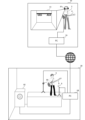
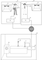
- FIG. 1 is a block diagram showing a configuration of a content information processing system.
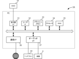
- FIG. 2 is a block diagram showing the configuration of PC1A.
- FIG. 2 is a block diagram showing the configuration of a PC1B.
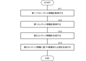
- 11 is a flowchart showing the operation of the PC 1A.
- FIG. 11 is a configuration diagram of a content information processing system according to a first modified example.
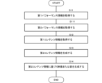
- FIG. 13 is a block diagram showing a configuration of a PC 1B according to a first modified example. 13 is a flowchart showing an operation of a PC 1A according to the first modified example.
- FIG. 11 is a configuration diagram of a content information processing system according to a second modified example.
- 13 is a flowchart showing an operation of a PC 1A according to a second modified example.
- FIG. 23 is a configuration diagram of a content information processing system according to a seventh modified example.
- FIG. 23 is a block diagram showing a configuration of a PC 1B according to a seventh modified
- FIG. 1 is a configuration diagram of a content information processing system according to this embodiment.
- the content information processing system includes a PC (personal computer) 1A installed in a first venue 10, and a PC 1B installed in a second venue 20.
- PC personal computer
- the first performer 3 at the first venue 10 connects the first musical instrument 4 to the PC 1A.
- the first performer 3 at the first venue 10 also connects a head mounted display (HMD) 51 and headphones 81 to the PC 1A.
- the first venue 10 is, for example, the home of the first performer 3.
- the first performer 3 at the first venue 10 performs a performance playing the first musical instrument 4.
- the second venue 20 is a live music venue, concert hall, etc.
- the PC 1B in the second venue 20 is connected to a camera 50, a microphone 8, and a speaker 82.
- the camera 50 and the microphone 8 are installed on the stage.
- the camera 50 acquires a video signal related to the image seen from the stage.
- the microphone 8 acquires an audio signal related to the sound heard on the stage.
- the first musical instrument 4 and the microphone 8 are examples of audio equipment. Note that in this embodiment, "playing” is not limited to playing an instrument, but also includes singing using a microphone.
- FIG. 2 is a block diagram showing the configuration of PC1A.
- FIG. 3 is a block diagram showing the configuration of PC1B.
- PC1A and PC1B are general-purpose information processing devices. The main configuration of PC1A and PC1B is the same.
- PC1A and PC1B each include a display interface (I/F) 31, a user I/F 32, a flash memory 33, a processor 34, a RAM 35, a communication I/F 36, and an audio I/F 37.
- I/F display interface
- the display I/F 31 is connected to a display.
- the display I/F 31 of PC1A is connected to a head mounted display (HMD) 51, which is an example of a display.
- the display I/F 31 of PC1B is not connected to anything in FIG. 3, but a general-purpose display such as an LCD may be connected. Note that, although this embodiment shows an example in which an HMD 51 is connected to PC1A, a display such as an LCD may also be connected to PC1A.
- the user I/F 32 is a keyboard, a mouse, or a touch panel that is layered on a display.
- the user I/F 32 is a touch panel
- the user I/F 32 and the display form a GUI (Graphical User Interface).
- the communication I/F 36 includes a network interface and is connected to a network such as the Internet via a router (not shown).
- a network such as the Internet via a router (not shown).
- PC1A and PC1B are connected via a network. That is, the first venue and the second venue are connected via a network.
- the audio I/F 37 has an audio terminal.
- the audio I/F 37 is connected to an audio device such as a musical instrument or a microphone via an audio cable and receives audio signals.
- the audio I/F 37 of PC 1A is connected to the first musical instrument 4 and receives audio signals related to performance sounds from the first musical instrument 4.
- the audio I/F 37 of PC 1B is connected to the microphone 8.
- the audio I/F 37 of PC 1B receives audio signals related to sounds from the second venue 20 picked up by the microphone 8.
- the audio I/F 37 is also connected to audio equipment such as a speaker or headphones. Headphones 81 are connected to the audio I/F 37 of PC 1A. Speakers 82 are connected to the audio I/F 37 of PC 1B. The audio I/F 37 outputs audio signals to audio equipment such as headphones 81 or speakers 82.
- Processor 34 is composed of a CPU, DSP, or SoC (System-on-a-Chip), and reads a program stored in flash memory 33, which is a storage medium, into RAM 35 to control each component of PC1A and PC1B. Flash memory 33 stores the program of this embodiment.
- the processor 34 encodes the audio signal received from the audio I/F 37 into an audio packet and transmits it to another device via the communication I/F 36.
- the communication I/F 36 of PC 1B receives a video signal received from the camera 50.
- the processor 34 of PC 1B encodes the video signal received from the camera 50 into a video packet and transmits it to another device via the communication I/F 36.
- the processor 34 also decodes audio packets received from other devices via the communication I/F 36, and outputs the decoded audio signals to the audio I/F 37.
- the processor 34 also decodes video packets received from other devices via the communication I/F 36, and outputs the decoded video signals to the display via the display I/F 31.
- FIG. 4 is a flowchart showing the operation of PC1A.
- PC1A acquires first performance information relating to a live performance by first performer 3 in first venue 10 (S11).
- the first performance information relating to the live performance of the first performer 3 includes, for example, a sound signal relating to the performance of the first instrument 4.
- the first performance information may be operation information of the first performer 3 on the first instrument 4.
- the operation information is information indicating which fret is being pressed, the timing at which the fret is pressed, the timing at which the fret is released, information indicating which string is being picked, the timing of picking, the picking speed, and whether or not a mute operation is performed.
- the operation information is time parameters such as pitch (note number), tone, attack, decay, sustain, and release.
- the operation information is obtained based on, for example, a motion sensor.
- the operation information can be obtained by a sensor mounted on the instrument. In the case of a guitar, the sensor mounted on the instrument is, for example, a fret sensor attached to each fret.
- PC 1A acquires first content information related to video or audio of second venue 20 (S12).
- PC 1A acquires, via the network, an audio signal from microphone 8 and a video signal related to second venue 20 captured by camera 50 as first content information.
- PC1A generates second content information based on the first performance information and the first content information (S13). Specifically, PC1A generates a mixed sound signal by mixing the sound signal of microphone 8 included in the first content information and the sound signal of first instrument 4 included in the first performance information. PC1A generates encoded data (e.g., MP4 data) including the mixed sound signal and a video signal related to second venue 20.
- encoded data e.g., MP4 data
- PC1A generates video or sound based on the second content information (S14). Specifically, PC1A decodes the encoded data and extracts a sound signal and a video signal. PC1A then outputs the extracted sound signal to headphones 81, and outputs a video related to second venue 20 to HMD 51. Note that in the process of S13, PC1A does not necessarily generate encoded data. For example, PC1A may output a mixed sound signal before encoding to headphones 81, and output a video signal before encoding to HMD 51 in S14.
- the first performer 3 can perceive himself as if he were performing in the second venue 20, even though he is in a remote location.
- the user can have a new customer experience in which he perceives himself as performing live in, for example, his favorite live music venue or concert hall.
- the image of the second venue 20 included in the first content information may be an image (digital twin) of a virtual space that imitates the actual second venue 20.
- the first content information may include information related to the shape of the second venue 20, such as 3D CAD data.
- PC 1A may render an image of the virtual space that imitates the second venue 20 based on the information related to the shape of the second venue 20 included in the first content information.
- the user can have a new customer experience in which they can perceive as if they are experiencing a live performance in, for example, their favorite live music venue or concert hall.
- the camera 50 may have a viewing angle that captures a certain direction, or a full viewing angle that captures the surroundings 360 degrees.
- the camera 50 may also have a mechanism for changing the viewing angle.
- the HMD 51 may be equipped with a sensor that detects the direction in which the user's head is facing.
- the PC 1A may change the viewing angle of the real camera 50, or change the viewing angle in the virtual space, depending on the direction in which the user's head is facing. This makes it even easier for the user to perceive that they are performing live at their favorite live music venue or concert hall.
- FIG. 5 is a configuration diagram of a content information processing system according to Modification 1. Components common to Fig. 1 are given the same reference numerals and descriptions thereof will be omitted.
- Fig. 6 is a block diagram showing the configuration of a PC 1B according to Modification 1. Components common to Fig. 3 are given the same reference numerals and descriptions thereof will be omitted.
- Fig. 7 is a flowchart showing the operation of a PC 1A according to Modification 1. Components common to Fig. 4 are given the same reference numerals and descriptions thereof will be omitted.
- a second performer 5 performs on stage at a second venue 20, playing a second musical instrument 6.
- a PC 1B at the second venue 20 is connected to the second musical instrument 6, a camera 50, a microphone 8, and a speaker 82.
- the audio I/F 37 of PC1B is connected to the second musical instrument 6 and the speaker 82.
- the audio I/F 37 of PC1B receives sound signals related to the performance sounds from the second musical instrument 6.
- PC1A further acquires second performance information relating to the live performance of the second performer in the second venue 20 (S111).
- the second performance information is a sound signal relating to the sound played on the second instrument 6 by the second performer 5 in the second venue 20.
- the processor 34 of PC1B transmits the sound signal of the second instrument 6 to PC1A.
- the second performance information may include operation information for the second instrument 6 instead of the sound signal relating to the sound played by the second performer 5.
- PC 1A In the process of S13, PC 1A generates second content information based on the first performance information, the first content information, and the second performance information. Specifically, PC 1A generates a mixed sound signal by mixing the sound signal of microphone 8 included in the first content information, the sound signal of first instrument 4 included in the first performance information, and the sound signal of second instrument 6 included in the second content information. PC 1A generates encoded data (e.g., MP4 data) including the mixed sound signal and a video signal related to second venue 20.
- encoded data e.g., MP4 data
- the first performer 3 even though he is in a remote location, can perceive himself as if he were in the second venue 20 and having a session with the second performer 5 at the second venue 20.
- This provides a new customer experience, allowing users to perceive themselves as if they are having a session at a favorite live music venue or concert hall, for example.
- the image of the second venue 20 included in the first content information may be an image of a virtual space that imitates the second venue 20.
- the image corresponding to the second performer 5 included in the image of the second venue 20 may be a 3D model placed in the virtual space.
- the 3D model of the virtual space and the performer becomes a digital twin that imitates the real second venue 20 and second performer 5.
- FIG. 8 is a configuration diagram of a content information processing system according to Modification 2. Components common to Fig. 1 are given the same reference numerals, and descriptions thereof will be omitted.
- Fig. 9 is a flowchart showing the operation of a PC 1A according to Modification 2. Components common to Fig. 4 are given the same reference numerals, and descriptions thereof will be omitted.
- PC1C is installed in the third venue 30.
- the configuration of PC1C is the same as that of PC1A.
- the first venue 10, the second venue 20, and the third venue 30 are connected via a network.
- a third performer 7 performs singing using a microphone 80 in a third venue 30.
- a PC 1C in the third venue 30 is connected to the microphone 80, an HMD 51, and headphones 81.
- PC1C acquires, via the network, the audio signal from the microphone 8 and the video signal of the second venue 20 captured by the camera 50 as the first content information.
- the audio I/F 37 of PC1C receives the audio signal related to the singing sound from the microphone 80.
- PC1C transmits the audio signal related to the singing sound to PC1A.
- PC1A further acquires third performance information related to the live performance of the third performer 7 in the third venue 30 (S121).
- the third performance information is an audio signal related to the singing sound of the third performer 7 in the third venue 30.
- PC 1A In the process of S13, PC 1A generates second content information based on the first performance information, the first content information, and the third performance information. Specifically, PC 1A generates a mixed sound signal by mixing the sound signal of microphone 8 included in the first content information, the sound signal of first instrument 4 included in the first performance information, and the sound signal of microphone 80 included in the third content information. PC 1A generates encoded data (e.g., MP4 data) including the mixed sound signal and a video signal related to second venue 20.
- encoded data e.g., MP4 data
- the first performer 3 although in a remote location, can perceive himself as if he were in the second venue 20 and having a session with the third performer 7 in the second venue 20.
- This provides a new customer experience in which the user can perceive themselves as if they were having a session with another performer in a remote location, for example, in a beloved live music venue or concert hall.
- the first content information according to the third modification includes information related to the delay in the second venue 20.
- the process of generating the second content information in the PC 1A includes a process of reproducing the delay in the second venue 20.
- the information on delay includes the delay of sound waves in the space in the second venue 20.
- the delay of sound waves in the space corresponds to the distance between the position of the speaker 82 and the position of the performer (e.g., microphone 8 or camera 50), the distance between the position of the speaker 82 and the position of the wall of the second venue 20, or the distance between the position of the wall of the second venue 20 and the position of the performer.
- the distance between the position of the speaker 82 and the position of the performer can be measured, for example, by outputting a test sound from the speaker 82 and acquiring the test sound with the microphone 8.
- the distance between the position of the speaker 82 and the position of the wall of the second venue 20 can be measured by outputting a test sound from the speaker 82 and acquiring the test sound with a measurement microphone (not shown).
- the distance between the position of the wall of the second venue 20 and the position of the performer can be measured by installing a test speaker at the position of the wall of the second venue 20, outputting a test sound from the speaker, and acquiring the test sound with the microphone 8. These distances may also be measured by outputting a test sound from the speaker 82 and acquiring an impulse response from the microphone 8.
- PC1A acquires information relating to the delay as the first content information. Then, PC1A performs signal processing relating to the delay on the sound signal of the first instrument 4 included in the first performance information. For example, if the information relating to the delay is an impulse response at the position of the performer measured in the second venue 20, PC1A performs processing to convolve the impulse response into the sound signal of the first instrument 4. In this way, PC1A reproduces the delay environment of the second venue 20.
- PC1A may accept an adjustment operation regarding the delay from the user.
- PC1A plays back the delay adjusted by the adjustment operation.
- the adjustment operation may be, for example, an operation of specifying an arbitrary live music venue or concert hall.
- PC1A obtains information regarding the delay corresponding to the specified live music venue or concert hall from, for example, a server. This allows the user to reproduce the reverberation of a location different from the reverberation of second venue 20.
- the first content information according to the fourth modification further includes information related to the shape of the second venue 20.
- PC 1A generates information related to the delay in the second venue 20 based on the information related to the shape of the second venue 20.
- PC 1A performs a process of reproducing the delay in the second venue 20 based on the generated information related to the delay.
- the information relating to the shape of the second venue 20 is, for example, 3D CAD data of the second venue 20.
- PC1A calculates the impulse response of the second venue 20 based on the information relating to the shape of the second venue 20 included in the first content information. At this time, PC1A may specify the position of the performer at any position within the second venue 20 and calculate the impulse response at that position, or may accept the specification of the performer's position from the user and calculate the impulse response at that position.
- PC1A performs a process of convolving the impulse response with the sound signal of the first instrument 4. In this way, PC1A reproduces the delay environment of the second venue 20.
- the first content information may include information on past images or sounds.
- the past images may be past images of the second venue 20 or past images of the first venue 10.
- PC1B records the images captured by the camera 50 or the sounds recorded by the microphone 8 in the flash memory 33 of its own device or in a server (not shown).
- PC1A receives information on past images or sounds of the second venue 20 from PC1B or a server (not shown).
- PC1A records the images captured by the camera (not shown) or the sounds recorded by the microphone installed in the first venue 10 in the flash memory 33 of its own device or in a server (not shown).
- PC1A receives information on past images or sounds of the first venue 10 from the flash memory 33 of its own device or in a server (not shown).
- the second content information may be distributed to another venue (fourth venue).
- PC1A distributes the second content information (encoded data such as MP4) generated in S13 of Fig. 4 to the information processing device of the fourth venue.
- PC1A may transmit the second content information (encoded data such as MP4) generated in S13 of Fig. 4 to a server (not shown), which distributes the information to the information processing device of the fourth venue.
- PC1A or the server may perform billing processing for the listener via the information processing device of the fourth venue.
- PC1A or the server distributes the second content information to the listener who has already been billed. This allows the first performer 3 to sell the content as a performance at any selected venue.
- PC1A or the server may also obtain the location information of the listener via the information processing device of the fourth venue.
- PC1A or the server may change the billing process according to the obtained location information.
- the location information is obtained, for example, by the GPS function of the information processing device.
- the location information may be identification information such as an ID associated with a specific location.
- the identification information is written on an exhibit or ticket as, for example, a two-dimensional code at each of the multiple locations.
- the identification information is read by a camera or the like of the information processing device and transmitted to PC1A or the server. As a result, the amount charged changes depending on the location where the second content information is viewed.
- the amount charged can be changed between when the fourth venue is a home and when the fourth venue is a location where a large number of listeners gather, such as a public viewing.
- the first performer 3 or the person who runs the event can charge a higher amount when distributing the second content information as a larger event.
- a lower amount can be charged to have a larger number of listeners view the information.
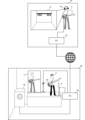
- Fig. 10 is a configuration diagram of a content information processing system according to Modification 7. Components common to Fig. 5 are given the same reference numerals, and descriptions thereof will be omitted.
- Fig. 11 is a block diagram showing the configuration of a PC 1B according to Modification 7. Components common to Fig. 6 are given the same reference numerals, and descriptions thereof will be omitted.
- a projector 71 is installed in the second venue 20 of the content information processing system according to the seventh modification.
- the projector 71 is connected to the PC 1B.
- PC1B receives video information relating to the first performer 3 from PC1A.
- the video information relating to the first performer 3 is a video signal captured by a camera (not shown) of the first performer 3.
- PC1B displays an image of the first performer 3 on the projector 71 based on the received video information relating to the first performer 3.
- the video information relating to the first performer 3 may be motion data that captures the movements of the first performer 3. If it is motion data, PC1B further acquires and renders 3D model data corresponding to the first performer 3, displays it on the projector 71, and uses the motion data to control the movement of the 3D model data.
- the listeners in the second venue 20 can perceive that the first performer 3 is in the second venue 20 and performing there.
- the first performer 3 (user) can obtain a new customer experience in which, while in a remote location, the listeners in the second venue 20 can perceive that the first performer 3 is in the second venue 20 and performing there.
- the PC 1A of the content information processing system may further acquire information on the reproduction environment of the second venue 20.
- the information on the reproduction environment includes, for example, information on the acoustic equipment (effector, amplifier, speaker, etc.) including the microphone 8 of the second venue 20, and information on the reverberation of the reproduction space.
- the sound acquired by the microphone 8 also changes depending on the acoustic equipment and the reverberation of the reproduction space of the second venue 20.
- the reverberation of the sound differs depending on the studio environment such as a trial room, a concert hall, outdoors, etc.
- the PC 1A performs signal processing on the sound of the generated second content information based on the information on the reproduction environment.
- the PC 1A may perform signal processing on the sound signal of the generated sound by convolving impulse response data of the reproduction environment.
- the PC 1A may also perform filter processing on the sound signal of the generated sound to simulate the acoustic equipment (effector, amplifier, speaker, etc.) installed in the second venue 20.
- the information on the playback environment includes parameters of a digital signal processing block that simulates, as a digital filter, the output characteristics relative to the input of each piece of audio equipment installed in the second venue 20.
- PC 1A applies signal processing to the sound signal of the generated sound using the parameters indicated in the information on the audio equipment. This allows PC 1A to reproduce, for the generated sound, the input/output characteristics of the audio equipment (effectors, amplifiers, speakers, etc.) installed in the second venue 20.
- the PC 1A reproduces the input/output characteristics of the audio equipment (effectors, amplifiers, speakers, etc.) installed in the second venue 20 for the sound of the first instrument 4 played by the first performer 3 in the first venue 10. This makes it even easier for users to perceive the performance as if they were in a live performance at their favorite live music venue or concert hall.
- the audio equipment effectors, amplifiers, speakers, etc.
- PC1A, PC1B, and PC1C are shown as examples of the content information processing device of the present invention.
- the content information processing device of the present invention is not limited to the above-mentioned PC1A, PC1B, and PC1C.
- an electronic musical instrument having the functions of the above-mentioned user I/F 32, flash memory 33, processor 34, RAM 35, communication I/F 36, audio I/F 37, etc. can also constitute a terminal of the present invention.
Landscapes
- Physics & Mathematics (AREA)
- Engineering & Computer Science (AREA)
- Acoustics & Sound (AREA)
- Multimedia (AREA)
- Signal Processing (AREA)
- Health & Medical Sciences (AREA)
- Audiology, Speech & Language Pathology (AREA)
- General Health & Medical Sciences (AREA)
- Two-Way Televisions, Distribution Of Moving Picture Or The Like (AREA)
- Stereophonic System (AREA)
Abstract
コンテンツ情報処理方法は、第1会場の第1演者のライブパフォーマンスに係る第1パフォーマンス情報を取得し、前記第1会場とネットワークで接続される第2会場の映像または音に係る第1コンテンツ情報を取得し、前記第1パフォーマンス情報および前記第1コンテンツ情報に基づいて第2コンテンツ情報を生成し、前記第2コンテンツ情報に基づく映像または音を生成する。
Description
この発明の一実施形態は、コンテンツ情報処理方法およびコンテンツ情報処理装置に関する。
特許文献1には、仮想聴取点と各収音点との距離に基づいて、各収音点に対応するチャンネルの収音信号に対して遅延及び/又は音圧の補正を行い、全チャンネルの収音信号を加算することにより、仮想聴取点に対応する合成音信号を生成する信号生成装置が開示されている。
特許文献2には、第1会場の第1の場所で発生する第1音源の音および該第1音源の位置情報に係る第1音源情報、および前記第1会場の第2の場所で発生する第2音源に係る第2音源情報、を配信データとして配信し、前記配信データをレンダリングして、前記第1音源の位置情報に基づく定位処理を施した前記第1音源の音と、前記第2音源の音と、を第2会場に提供するライブデータ配信方法が開示されている。
それぞれのオーディオオブジェクトの音声データと、複数の想定聴取位置のそれぞれに対する、前記音声データのレンダリングパラメータとを含むコンテンツを取得する取得部と、選択された所定の前記想定聴取位置に対する前記レンダリングパラメータに基づいて前記音声データのレンダリングを行い、音声信号を出力するレンダリング部とを備える再生装置。第1パフォーマンスにおける、演者の身体の動きを検出し、演者に関連付けられるアバターオブジェクトを仮想空間に配置し、検出した演者の身体の動きに応じて、アバターオブジェクトに、第2パフォーマンスを実行させることが記載されている。
本開示のひとつの態様は、遠隔地の会場でパフォーマンスを行っている様に知覚することができるコンテンツ情報処理方法を提供することを目的とする。
本発明の一実施形態に係るコンテンツ情報処理方法は、第1会場の第1演者のライブパフォーマンスに係る第1パフォーマンス情報を取得し、前記第1会場とネットワークで接続される第2会場の映像または音に係る第1コンテンツ情報を取得し、前記第1パフォーマンス情報および前記第1コンテンツ情報に基づいて第2コンテンツ情報を生成し、前記第2コンテンツ情報に基づく映像または音を生成する。
本発明の一実施形態によれば、遠隔地の会場でパフォーマンスを行っている様に知覚することができる。
図1は、本実施形態に係るコンテンツ情報処理システムの構成図である。コンテンツ情報処理システムは、第1会場10に設置されたPC(パーソナルコンピュータ)1A、および第2会場20に設置されたPC1Bを備える。
第1会場10の第1演者3は、PC1Aに第1楽器4を接続する。また、第1会場10の第1演者3は、PC1Aにヘッドマウントディスプレイ(HMD)51およびヘッドフォン81を接続する。第1会場10は、例えば第1演者3の自宅である。第1会場10の第1演者3は、第1楽器4を演奏するパフォーマンスを行う。
第2会場20は、ライブハウスやコンサートホール等である。第2会場20のPC1Bは、カメラ50、マイク8、およびスピーカ82を接続する。カメラ50およびマイク8は、ステージ上に設置される。カメラ50は、ステージ上から見た映像に係る映像信号を取得する。マイク8は、ステージ上で聞こえる音に係る音信号を取得する。
本実施形態では一例として、第1楽器4およびマイク8は音響機器の一例である。なお、本実施形態において、「演奏」とは楽器の演奏に限るものではなく、マイクを用いた歌唱も含む。
図2は、PC1Aの構成を示すブロック図である。図3は、PC1Bの構成を示すブロック図である。PC1AおよびPC1Bは、汎用の情報処理装置である。PC1AおよびPC1Bの主要構成は同じである。
PC1AおよびPC1Bは、表示器インタフェース(I/F)31、ユーザI/F32、フラッシュメモリ33、プロセッサ34、RAM35、通信I/F36、およびオーディオI/F37を備えている。
表示器I/F31は、表示器に接続される。PC1Aの表示器I/F31は、表示器の一例であるヘッドマウントディスプレイ(HMD)51に接続される。PC1Bの表示器I/F31は、図3では何も接続されていないが、LCD等の汎用の表示器が接続されてもよい。なお、本実施形態では、PC1AにHMD51が接続される例を示しているが、PC1AにはLCD等の表示器が接続されてもよい。
ユーザI/F32は、キーボード、マウス、あるいは表示器に積層されるタッチパネルである。ユーザI/F32がタッチパネルである場合、該ユーザI/F32は、表示器とともに、GUI(Graphical User Interface)を構成する。
通信I/F36は、ネットワークインタフェースを含み、ルータ(不図示)を介してインターネット等のネットワークに接続される。図1の例では、PC1AおよびPC1Bは、ネットワークを介して接続される。すなわち、第1会場および第2会場は、ネットワークを介して接続される。
オーディオI/F37は、オーディオ端子を有する。オーディオI/F37は、オーディオケーブルを介して楽器またはマイク等の音響機器に接続され、音信号を受け付ける。本実施形態では、PC1AのオーディオI/F37は、第1楽器4に接続され、第1楽器4から演奏音に係る音信号を受け付ける。PC1BのオーディオI/F37は、マイク8に接続される。PC1BのオーディオI/F37は、マイク8で収音した第2会場20の音に係る音信号を受け付ける。
また、オーディオI/F37は、スピーカまたはヘッドフォン等の音響機器に接続される。PC1AのオーディオI/F37にはヘッドフォン81が接続されている。PC1BのオーディオI/F37にはスピーカ82が接続されている。オーディオI/F37は、ヘッドフォン81またはスピーカ82等の音響機器に音信号を出力する。
プロセッサ34は、CPU,DSP、あるいはSoC(System-on-a-Chip)等からなり、記憶媒体であるフラッシュメモリ33に記憶されているプログラムをRAM35に読み出して、PC1AおよびPC1Bの各構成を制御する。フラッシュメモリ33は、本実施形態のプログラムを記憶している。
プロセッサ34は、オーディオI/F37から受け付けた音信号を、オーディオパケットにエンコードして通信I/F36を介して他装置に送信する。
また、PC1Bの通信I//F36は、カメラ50から受け付けた映像信号を受け付ける。PC1Bのプロセッサ34は、カメラ50から受け付けた映像信号を映像パケットにエンコードして通信I/F36を介して他装置に送信する。
また、プロセッサ34は、通信I/F36を介して他装置から受信したオーディオパケットをデコードし、デコードした音信号をオーディオI/F37に出力する。また、プロセッサ34は、通信I/F36を介して他装置から受信した映像パケットをデコードし、デコードした映像信号を表示器I/F31を介して表示器に出力する。
図4は、PC1Aの動作を示すフローチャートである。PC1Aは、第1会場10の第1演者3のライブパフォーマンスに係る第1パフォーマンス情報を取得する(S11)。
第1演者3のライブパフォーマンスに係る第1パフォーマンス情報は、例えば第1楽器4の演奏に係る音信号を含む。あるいは、第1パフォーマンス情報は、第1演者3の第1楽器4に対する操作情報でもよい。操作情報とは、例えばギターであれば、どのフレットを押下しているか示す情報、該フレットを押下したタイミング、離したタイミング、どの弦をピッキングしたかを示す情報、ピッキングのタイミング、ピッキングの速さ、あるいはミュート操作の有無、等である。また、操作情報とは、例えばシンセサイザー等の鍵盤楽器では、音高(ノートナンバー)、音色、アタック、ディケイ、サスティン、リリース等の時間パラメータ等である。操作情報は、例えばモーションセンサに基づいて取得される。あるいは操作情報は、楽器に搭載されたセンサにより取得することも可能である。楽器に搭載されたセンサとは、例えばギターの場合には、フレット毎に取り付けられたフレットセンサである。
次に、PC1Aは、第2会場20の映像または音に係る第1コンテンツ情報を取得する(S12)。図1の例では、PC1Aは、ネットワークを介して、マイク8の音信号と、カメラ50で撮影した第2会場20に係る映像信号と、を第1コンテンツ情報として取得する。
PC1Aは、第1パフォーマンス情報および第1コンテンツ情報に基づいて第2コンテンツ情報を生成する(S13)。具体的には、PC1Aは、第1コンテンツ情報に含まれるマイク8の音信号と、第1パフォーマンス情報に含まれる第1楽器4の音信号と、を混合した混合音信号を生成する。PC1Aは、混合音信号および第2会場20に係る映像信号を含むエンコードデータ(例えばMP4データ)を生成する。
そして、PC1Aは、第2コンテンツ情報に基づく映像または音を生成する(S14)。具体的には、PC1Aは、上記エンコードデータをデコードし、音信号および映像信号を取り出す。そして、PC1Aは、取り出した音信号をヘッドフォン81に出力し、第2会場20に係る映像をHMD51に出力する。なお、S13の処理において、PC1Aは、エンコードデータを生成することは必須ではない。例えば、PC1Aは、S14において、エンコード前の混合音信号をヘッドフォン81に出力し、エンコード前の映像信号をHMD51に出力してもよい。
これにより、第1演者3は、遠隔地でありながらあたかも第2会場20にいてパフォーマンスを行っているように知覚することができる。つまり、利用者は、例えばあこがれのライブハウスやコンサートホールでライブパフォーマンスをしているように知覚することができるという新たな顧客体験を得ることができる。
なお、第1コンテンツ情報が含む第2会場20の映像は、実在の第2会場20を模した仮想空間の映像(デジタルツイン)であってもよい。この場合、第1コンテンツ情報は、3DCADデータ等の第2会場20の形状に係る情報を含んでいてもよい。PC1Aは、第1コンテンツ情報に含まれる第2会場20の形状に係る情報に基づいて、第2会場20を模した仮想空間の映像をレンダリングしてもよい。この場合も、利用者は、例えばあこがれのライブハウスやコンサートホールでライブパフォーマンスをしているように知覚することができるという新たな顧客体験を得ることができる。
また、カメラ50は、ある一方向を撮影する視野角を有していてもよいし、360度周囲を撮影する全周視野角を有していてもよい。また、カメラ50は、視野角を変更する機構を有していてもよい。HMD51は、利用者の頭部の向いている方向を検出するセンサを備えていてもよい。PC1Aは、利用者の頭部の向いている方向に応じて、現実のカメラ50の視野角を変更する、あるいは仮想空間内の視野角を変更してもよい。これにより、利用者は、あこがれのライブハウスやコンサートホールでライブパフォーマンスをしているようにさらに知覚し易くなる。
(変形例1)
図5は、変形例1に係るコンテンツ情報処理システムの構成図である。図1と共通する構成は同一の符号を付し、説明を省略する。図6は、変形例1に係るPC1Bの構成を示すブロック図である。図3と共通する構成は同一の符号を付し、説明を省略する。図7は、変形例1に係るPC1Aの動作を示すフローチャートである。図4と共通する構成は同一の符号を付し、説明を省略する。
図5は、変形例1に係るコンテンツ情報処理システムの構成図である。図1と共通する構成は同一の符号を付し、説明を省略する。図6は、変形例1に係るPC1Bの構成を示すブロック図である。図3と共通する構成は同一の符号を付し、説明を省略する。図7は、変形例1に係るPC1Aの動作を示すフローチャートである。図4と共通する構成は同一の符号を付し、説明を省略する。
変形例1では、第2会場20において、第2演者5がステージ上で第2楽器6を演奏するパフォーマンスを行う。第2会場20のPC1Bは、第2楽器6、カメラ50、マイク8、およびスピーカ82を接続する。
PC1BのオーディオI/F37は、第2楽器6およびスピーカ82に接続される。PC1BのオーディオI/F37は、第2楽器6から演奏音に係る音信号を受け付ける。
PC1Aは、さらに、第2会場20の第2演者のライブパフォーマンス係る第2パフォーマンス情報を取得する(S111)。第2パフォーマンス情報は、第2会場20にいる第2演者5による第2楽器6の演奏音に係る音信号である。PC1Bのプロセッサ34は、第2楽器6の音信号をPC1Aに送信する。なお、第2パフォーマンス情報は、第2演者5の演奏音に係る音信号に代えて、第2楽器6に対する操作情報を含んでいてもよい。
PC1Aは、S13の処理において、第1パフォーマンス情報、第1コンテンツ情報、および第2パフォーマンス情報に基づいて第2コンテンツ情報を生成する。具体的には、PC1Aは、第1コンテンツ情報に含まれるマイク8の音信号、第1パフォーマンス情報に含まれる第1楽器4の音信号、および第2コンテンツ情報に含まれる第2楽器6の音信号を混合した混合音信号を生成する。PC1Aは、混合音信号および第2会場20に係る映像信号を含むエンコードデータ(例えばMP4データ)を生成する。
これにより、第1演者3は、遠隔地でありながらあたかも第2会場20にいて第2会場20の第2演者5とセッションを行っているように知覚することができる。利用者は、例えばあこがれのライブハウスやコンサートホールでセッションをしているように知覚することができるという新たな顧客体験を得ることができる。
なお、上述した様に、第1コンテンツ情報が含む第2会場20の映像は、第2会場20を模した仮想空間の映像であってもよい。この場合、第2会場20の映像の中に含まれる第2演者5に対応する映像は、仮想空間内に配置される3Dモデルあってもよい。この場合、仮想空間および演者の3Dモデルは、実在の第2会場20および第2演者5を模したデジタルツインとなる。
(変形例2)
図8は、変形例2に係るコンテンツ情報処理システムの構成図である。図1と共通する構成は同一の符号を付し、説明を省略する。図9は、変形例2に係るPC1Aの動作を示すフローチャートである。図4と共通する構成は同一の符号を付し、説明を省略する。
図8は、変形例2に係るコンテンツ情報処理システムの構成図である。図1と共通する構成は同一の符号を付し、説明を省略する。図9は、変形例2に係るPC1Aの動作を示すフローチャートである。図4と共通する構成は同一の符号を付し、説明を省略する。
変形例2では、第3会場30にPC1Cが設置されている。PC1Cの構成は、PC1Aと同じである。変形例2では、第1会場10、第2会場20、および第3会場30がネットワークを介して接続される。
変形例2では、第3会場30において、第3演者7がマイク80を用いて歌唱するパフォーマンスを行う。第3会場30のPC1Cは、マイク80、HMD51、およびヘッドフォン81を接続する。
PC1Cは、ネットワークを介して、マイク8の音信号と、カメラ50で撮影した第2会場20に係る映像信号と、を第1コンテンツ情報として取得する。PC1CのオーディオI/F37は、マイク80から歌唱音に係る音信号を受け付ける。PC1Cは、歌唱音に係る音信号をPC1Aに送信する。
PC1Aは、さらに、第3会場30の第3演者7のライブパフォーマンスに係る第3パフォーマンス情報を取得する(S121)。第3パフォーマンス情報は、第3会場30にいる第3演者7による歌唱音に係る音信号である。
PC1Aは、S13の処理において、第1パフォーマンス情報、第1コンテンツ情報、および第3パフォーマンス情報に基づいて第2コンテンツ情報を生成する。具体的には、PC1Aは、第1コンテンツ情報に含まれるマイク8の音信号、第1パフォーマンス情報に含まれる第1楽器4の音信号、および第3コンテンツ情報に含まれるマイク80の音信号を混合した混合音信号を生成する。PC1Aは、混合音信号および第2会場20に係る映像信号を含むエンコードデータ(例えばMP4データ)を生成する。
これにより、第1演者3は、遠隔地でありながらあたかも第2会場20にいて第2会場20の第3演者7とセッションを行っているように知覚することができる。利用者は、例えばあこがれのライブハウスやコンサートホールにおいて、遠隔地の他の演者とセッションをしているように知覚することができるという新たな顧客体験を得ることができる。
(変形例3)
変形例3に係る第1コンテンツ情報は、第2会場20の遅延に関する情報を含む。PC1Aにおいて第2コンテンツ情報を生成する処理は、第2会場20の遅延を再生する処理を含む。
変形例3に係る第1コンテンツ情報は、第2会場20の遅延に関する情報を含む。PC1Aにおいて第2コンテンツ情報を生成する処理は、第2会場20の遅延を再生する処理を含む。
遅延に関する情報とは、第2会場20における空間内の音波の遅延を含む。空間内の音波の遅延とは、スピーカ82の位置と演者の位置(例えばマイク8またはカメラ50)との距離、スピーカ82の位置と第2会場20の壁面の位置との距離、または第2会場20の壁面の位置と演者の位置との距離に対応する。スピーカ82の位置と演者の位置(例えばマイク8またはカメラ50)との距離は、例えば、スピーカ82からテスト音を出力し、マイク8で当該テスト音を取得することにより測定できる。スピーカ82の位置と第2会場20の壁面の位置との距離は、スピーカ82からテスト音を出力し、測定用のマイク(不図示)で当該テスト音を取得することにより測定できる。第2会場20の壁面の位置との演者の位置との距離は、第2会場20の壁面の位置にテスト用のスピーカを設置し、当該スピーカからテスト音を出力し、マイク8で当該テスト音を取得することにより測定できる。また、これらの距離は、スピーカ82からテスト音を出力し、マイク8でインパルス応答を取得することにより測定してもよい。
PC1Aは、第1コンテンツ情報として、当該遅延に関する情報を取得する。そして、PC1Aは、第1パフォーマンス情報に含まれる第1楽器4の音信号に遅延に関する信号処理を施す。例えば、遅延に関する情報が第2会場20で測定された、演者の位置におけるインパルス応答である場合、当該インパルス応答を第1楽器4の音信号に畳み込む処理を行う。これにより、PC1Aは、第2会場20の遅延環境を再現する。
したがって、利用者は、あこがれのライブハウスやコンサートホールでライブパフォーマンスをしているようにさらに知覚し易くなる。
なお、PC1Aは、利用者から遅延に関する調整操作を受け付けてもよい。PC1Aは、調整操作により調整された遅延を再生する。調整操作とは、例えば任意のライブハウスやコンサートホールを指定する操作であってもよい。PC1Aは、指定されたライブハウスやコンサートホールに対応する、遅延に関する情報を例えばサーバ等から取得する。これにより、利用者は、第2会場20の響きとは異なる場所の響きを再生させることができる。
(変形例4)
変形例4に係る第1コンテンツ情報は、さらに第2会場20の形状に係る情報を含む。PC1Aは、第2会場20の形状に係る情報に基づいて、第2会場20の遅延に関する情報を生成する。PC1Aは、生成した当該遅延に関する情報に基づいて、第2会場20の遅延を再生する処理を行う。
変形例4に係る第1コンテンツ情報は、さらに第2会場20の形状に係る情報を含む。PC1Aは、第2会場20の形状に係る情報に基づいて、第2会場20の遅延に関する情報を生成する。PC1Aは、生成した当該遅延に関する情報に基づいて、第2会場20の遅延を再生する処理を行う。
第2会場20の形状に係る情報とは、例えば第2会場20の3DCADデータである。PC1Aは、第1コンテンツ情報に含まれる第2会場20の形状に係る情報に基づいて、第2会場20のインパルス応答を計算する。この時、PC1Aは、第2会場20内の任意の位置に演者の位置を指定し、当該位置におけるインパルス応答を計算してもよいし、利用者から演者の位置の指定を受け付けて、当該位置におけるインパルス応答を計算してもよい。
PC1Aは、当該インパルス応答を第1楽器4の音信号に畳み込む処理を行う。これにより、PC1Aは、第2会場20の遅延環境を再現する。
この場合も、利用者は、あこがれのライブハウスやコンサートホールでライブパフォーマンスをしているようにさらに知覚し易くなる。
(変形例5)
第1コンテンツ情報は、過去の映像または音に関する情報を含んでいてもよい。過去の映像は、第2会場20の過去の映像でもよいし、第1会場10の過去の映像でもよい。第2会場20の過去の映像である場合、PC1Bは、カメラ50で撮影した映像、またはマイク8で録音した音を自装置のフラッシュメモリ33または不図示のサーバに記録する。PC1Aは、PC1Bまたは不図示のサーバから第2会場20の過去の映像または音に関する情報を受信する。第1会場10の過去の映像でる場合、PC1Aは、第1会場10に設置された不図示のカメラで撮影した映像、またはマイクで録音した音を自装置のフラッシュメモリ33または不図示のサーバに記録する。PC1Aは、時装置のフラッシュメモリ33または不図示のサーバから第1会場10の過去の映像または音に関する情報を受信する。
第1コンテンツ情報は、過去の映像または音に関する情報を含んでいてもよい。過去の映像は、第2会場20の過去の映像でもよいし、第1会場10の過去の映像でもよい。第2会場20の過去の映像である場合、PC1Bは、カメラ50で撮影した映像、またはマイク8で録音した音を自装置のフラッシュメモリ33または不図示のサーバに記録する。PC1Aは、PC1Bまたは不図示のサーバから第2会場20の過去の映像または音に関する情報を受信する。第1会場10の過去の映像でる場合、PC1Aは、第1会場10に設置された不図示のカメラで撮影した映像、またはマイクで録音した音を自装置のフラッシュメモリ33または不図示のサーバに記録する。PC1Aは、時装置のフラッシュメモリ33または不図示のサーバから第1会場10の過去の映像または音に関する情報を受信する。
これにより、利用者は、例えば現存しない、あこがれのライブハウスやコンサートホールでライブパフォーマンスをしているように知覚することができるという新たな顧客体験を得ることができる。
(変形例6)
第2コンテンツ情報は、さらに他の会場(第4会場)に配信してもよい。PC1Aは、図4のS13で生成した第2コンテンツ情報(MP4等のエンコードデータ)を第4会場の情報処理装置に配信する。または、PC1Aは、図4のS13で生成した第2コンテンツ情報(MP4等のエンコードデータ)を不図示のサーバに送信し、該サーバが第4会場の情報処理装置に配信してもよい。
第2コンテンツ情報は、さらに他の会場(第4会場)に配信してもよい。PC1Aは、図4のS13で生成した第2コンテンツ情報(MP4等のエンコードデータ)を第4会場の情報処理装置に配信する。または、PC1Aは、図4のS13で生成した第2コンテンツ情報(MP4等のエンコードデータ)を不図示のサーバに送信し、該サーバが第4会場の情報処理装置に配信してもよい。
さらに、PC1Aまたはサーバは、第4会場の情報処理装置を介して、リスナに課金処理を行ってもよい。PC1Aまたはサーバは、課金処理済のリスナに対して第2コンテンツ情報を配信する。これにより、第1演者3は、選択した任意の会場においてパフォーマンスを行っているコンテンツとして販売することができる。
また、PC1Aまたはサーバは、第4会場の情報処理装置を介して、リスナの位置情報を取得してもよい。PC1Aまたはサーバは、取得した位置情報に応じて課金処理を変更してもよい。位置情報は、例えば情報処理装置のGPS機能により取得される。あるいは、位置情報は、特定の場所に対応付けられたID等の識別情報であってもよい。識別情報は、複数の場所のそれぞれに例えば2次元コードとして展示あるいはチケット等に記載されている。識別情報は、情報処理装置のカメラ等により読み込まれて、PC1Aまたはサーバに送信される。これにより、課金される額は、第2コンテンツ情報を視聴する場所に応じて変化する。したがって、例えば、第4会場が自宅である場合と、第4会場がパブリックビューイング等の多数リスナが集まる場所と、で課金額を変更することができる。第1演者3あるいはイベントの実行者は、例えばより大規模なイベントとして第2コンテンツ情報を配信する場合にはより高額な課金を実行することができる。あるいは第1演者3が個人で小規模なイベントとして第2コンテンツ情報を配信する場合には低額な課金としてより多数のリスナに視聴してもらうこともできる。
(変形例7)
図10は、変形例7に係るコンテンツ情報処理システムの構成図である。図5と共通する構成は同一の符号を付し、説明を省略する。図11は、変形例7に係るPC1Bの構成を示すブロック図である。図6と共通する構成は同一の符号を付し、説明を省略する。
図10は、変形例7に係るコンテンツ情報処理システムの構成図である。図5と共通する構成は同一の符号を付し、説明を省略する。図11は、変形例7に係るPC1Bの構成を示すブロック図である。図6と共通する構成は同一の符号を付し、説明を省略する。
変形例7に係るコンテンツ情報処理システムの第2会場20は、プロジェクタ71が設置されている。プロジェクタ71は、PC1Bに接続される。
PC1Bは、PC1Aから第1演者3に係る映像情報を受信する。第1演者3に係る映像情報は、第1演者3を不図示のカメラで撮影した映像信号である。この場合、PC1Bは、受信した第1演者3に係る映像情報に基づいて、プロジェクタ71に第1演者3の映像を表示する。あるいは、第1演者3に係る映像情報は、第1演者3の動作をキャプチャしたモーションデータであってもよい。モーションデータである場合、PC1Bは、さらに第1演者3に対応する3Dモデルデータを取得してレンダリングしてプロジェクタ71に表示し、当該モーションデータを用いて3Dモデルデータの動作を制御する。
これにより、第2会場20に居るリスナは、第1演者3が第2会場20に居てパフォーマンスを行っているように知覚することができる。すなわち、第1演者3(利用者)は、遠隔地にいながら、第2会場20のリスナに対して、第1演者3が第2会場20に居てパフォーマンスを行っているように知覚させることができるという新たな顧客体験を得ることができる。
(変形例8)
変形例8に係るコンテンツ情報処理システムのPC1Aは、第2会場20の再生環境に関する情報をさらに取得してもよい。再生環境に関する情報は、例えば第2会場20のマイク8を含む音響機器(エフェクタ、アンプ、スピーカ等)に関する情報、および再生空間の響きに関する情報を含む。マイク8で取得する音は、第2会場20の音響機器および再生空間の響きによっても変化する。例えば、音の響きは、試奏室等のスタジオ環境、コンサートホール、屋外、等によって異なる。PC1Aは、当該再生環境に関する情報に基づいて、生成した第2コンテンツ情報の音に信号処理を施す。例えば、PC1Aは、生成した音の音信号に対して、再生環境のインパルス応答データを畳み込む信号処理を行ってもよい。また、PC1Aは、生成した音の音信号に対して、第2会場20に設置されている音響機器(エフェクタ、アンプ、スピーカ等)をシミュレートするフィルタ処理を施してもよい。具体的には、再生環境に関する情報は、第2会場20に設置されている各音響機器の入力に対する出力の特性をデジタルフィルタとしてシミュレートしたデジタル信号処理ブロックのパラメータを含む。PC1Aは、生成した音の音信号に対して、音響機器に関する情報で示されたパラメータの信号処理を施す。これにより、PC1Aは、生成した音に対して、第2会場20に設置されている音響機器(エフェクタ、アンプ、スピーカ等)の入出力特性を再現することができる。
変形例8に係るコンテンツ情報処理システムのPC1Aは、第2会場20の再生環境に関する情報をさらに取得してもよい。再生環境に関する情報は、例えば第2会場20のマイク8を含む音響機器(エフェクタ、アンプ、スピーカ等)に関する情報、および再生空間の響きに関する情報を含む。マイク8で取得する音は、第2会場20の音響機器および再生空間の響きによっても変化する。例えば、音の響きは、試奏室等のスタジオ環境、コンサートホール、屋外、等によって異なる。PC1Aは、当該再生環境に関する情報に基づいて、生成した第2コンテンツ情報の音に信号処理を施す。例えば、PC1Aは、生成した音の音信号に対して、再生環境のインパルス応答データを畳み込む信号処理を行ってもよい。また、PC1Aは、生成した音の音信号に対して、第2会場20に設置されている音響機器(エフェクタ、アンプ、スピーカ等)をシミュレートするフィルタ処理を施してもよい。具体的には、再生環境に関する情報は、第2会場20に設置されている各音響機器の入力に対する出力の特性をデジタルフィルタとしてシミュレートしたデジタル信号処理ブロックのパラメータを含む。PC1Aは、生成した音の音信号に対して、音響機器に関する情報で示されたパラメータの信号処理を施す。これにより、PC1Aは、生成した音に対して、第2会場20に設置されている音響機器(エフェクタ、アンプ、スピーカ等)の入出力特性を再現することができる。
この場合、PC1Aは、第1会場10の第1演者3が演奏する第1楽器4の演奏音に対して、第2会場20に設置されている音響機器(エフェクタ、アンプ、スピーカ等)の入出力特性を再現する。したがって、利用者は、あこがれのライブハウスやコンサートホールでライブパフォーマンスをしているようにさらに知覚し易くなる。
(その他の例)
上述の例では、本発明のコンテンツ情報処理装置の例として、PC1A、PC1BおよびPC1Cを示した。しかし、本発明のコンテンツ情報処理装置は、上述のPC1A、PC1BおよびPC1Cに限らない。例えば、上述のユーザI/F32、フラッシュメモリ33、プロセッサ34、RAM35、通信I/F36、およびオーディオI/F37等の機能を備えた電子楽器も本発明の端末を構成することができる。
上述の例では、本発明のコンテンツ情報処理装置の例として、PC1A、PC1BおよびPC1Cを示した。しかし、本発明のコンテンツ情報処理装置は、上述のPC1A、PC1BおよびPC1Cに限らない。例えば、上述のユーザI/F32、フラッシュメモリ33、プロセッサ34、RAM35、通信I/F36、およびオーディオI/F37等の機能を備えた電子楽器も本発明の端末を構成することができる。
本実施形態の説明は、すべての点で例示であって、制限的なものではないと考えられるべきである。本発明の範囲は、上述の実施形態ではなく、請求の範囲によって示される。さらに、本発明の範囲は、請求の範囲と均等の範囲を含む。
3:第1演者、4:楽器、5:第2演者、6:楽器、7:第3演者、8:マイク、10:第1会場、20:第2会場、30:第3会場、31:表示器I/F、32:ユーザI/F、33:フラッシュメモリ、34:プロセッサ、35:RAM、36:通信I/F、37:オーディオI/F、50:カメラ、51:HMD、71:プロジェクタ、80:マイク、81:ヘッドフォン、82:スピーカ
Claims (20)
- 第1会場の第1演者のライブパフォーマンスに係る第1パフォーマンス情報を取得し、
前記第1会場とネットワークで接続される第2会場の映像または音に係る第1コンテンツ情報を取得し、
前記第1パフォーマンス情報および前記第1コンテンツ情報に基づいて第2コンテンツ情報を生成し、
前記第2コンテンツ情報に基づく映像または音を生成する、
コンテンツ情報処理方法。 - 前記第2会場の第2演者のライブパフォーマンス係る第2パフォーマンス情報を取得し、
前記第1パフォーマンス情報、前記第1コンテンツ情報、および前記第2パフォーマンス情報に基づいて前記第2コンテンツ情報を生成する、
請求項1に記載のコンテンツ情報処理方法。 - 第3会場の第3演者のライブパフォーマンスに係る第3パフォーマンス情報を取得し、
前記第1パフォーマンス情報、前記第1コンテンツ情報、および前記第3パフォーマンス情報に基づいて前記第2コンテンツ情報を生成する、
請求項1に記載のコンテンツ情報処理方法。 - さらに、前記第2会場の再生環境に関する情報を取得し、
前記再生環境に関する情報に基づいて、生成した前記音に信号処理を施す、
請求項1に記載のコンテンツ情報処理方法。 - 前記第1パフォーマンス情報は、前記第1演者の演奏する第1楽器の演奏音を含み、
前記第2コンテンツ情報は、前記第1楽器の演奏音を含み、
前記再生環境に関する情報に基づいて、前記第1楽器の演奏音に前記信号処理を施す、
請求項4に記載のコンテンツ情報処理方法。 - 前記第2コンテンツ情報は、前記第1会場の音および前記第2会場の音を混合した混合音を含む、
請求項1に記載のコンテンツ情報処理方法。 - 前記第1コンテンツ情報は、前記第2会場における音波の遅延に関する情報を含み、
前記第2コンテンツ情報を生成する処理は、前記第2会場における音波の遅延を再生する処理を含む、
請求項1乃至請求項6のいずれか1項に記載のコンテンツ情報処理方法。 - 前記第1コンテンツ情報は、さらに前記第2会場の形状に係る情報を含み、
前記第2会場の形状に係る情報に基づいて、前記第2会場における音波の遅延に関する情報を生成し、
前記第2コンテンツ情報を生成する処理は、前記第2会場における音波の遅延を再生する処理を含む、
請求項1乃至請求項6のいずれか1項に記載のコンテンツ情報処理方法。 - 前記第1コンテンツ情報は、前記第2会場における音波の遅延に関する情報を含み、
利用者から前記遅延に関する調整操作を受け付け、
前記第2コンテンツ情報を生成する処理は、前記調整操作により調整された遅延を再生する処理を含む、
請求項1乃至請求項6のいずれか1項に記載のコンテンツ情報処理方法。 - 前記第2コンテンツ情報に基づく映像または音は、過去の映像または音を含む、
請求項1乃至請求項6のいずれか1項に記載のコンテンツ情報処理方法。 - 前記第2コンテンツ情報を、第4会場に配信する、
請求項1乃至請求項6のいずれか1項に記載のコンテンツ情報処理方法。 - 前記第4会場のリスナに対して課金処理を行い、
前記課金処理済のリスナに前記第2コンテンツ情報を配信する、
請求項11に記載のコンテンツ情報処理方法。 - 前記第4会場の前記リスナの位置情報を取得し、
前記位置情報に応じて前記課金処理を変更する、
請求項12に記載のコンテンツ情報処理方法。 - 第1会場の第1演者のライブパフォーマンスに係る第1パフォーマンス情報を取得し、
前記第1会場とネットワークで接続される第2会場の映像または音に係る第1コンテンツ情報を取得し、
前記第1パフォーマンス情報および前記第1コンテンツ情報に基づいて第2コンテンツ情報を生成し、
前記第2コンテンツ情報に基づく映像または音を生成する、
プロセッサを備えたコンテンツ情報処理装置。 - 前記プロセッサは、
前記第2会場の第2演者のライブパフォーマンス係る第2パフォーマンス情報を取得し、
前記第1パフォーマンス情報、前記第1コンテンツ情報、および前記第2パフォーマンス情報に基づいて前記第2コンテンツ情報を生成する、
請求項14に記載のコンテンツ情報処理装置。 - 前記プロセッサは、
第3会場の第3演者のライブパフォーマンスに係る第3パフォーマンス情報を取得し、
前記第1パフォーマンス情報、前記第1コンテンツ情報、および前記第3パフォーマンス情報に基づいて前記第2コンテンツ情報を生成する、
請求項14に記載のコンテンツ情報処理装置。 - 前記第1コンテンツ情報は、前記第2会場における音波の遅延に関する情報を含み、
前記第2コンテンツ情報を生成する処理は、前記第2会場における音波の遅延を再生する処理を含む、
請求項14乃至請求項16のいずれか1項に記載のコンテンツ情報処理装置。 - 前記第1コンテンツ情報は、さらに前記第2会場の形状に係る情報を含み、
前記プロセッサは、前記第2会場の形状に係る情報に基づいて、前記第2会場における音波の遅延に関する情報を生成し、
前記第2コンテンツ情報を生成する処理は、前記第2会場における音波の遅延を再生する処理を含む、
請求項14乃至請求項16のいずれか1項に記載のコンテンツ情報処理装置。 - 前記第1コンテンツ情報は、前記第2会場の過去の映像または音に関する情報を含む、
請求項14乃至請求項16のいずれか1項に記載のコンテンツ情報処理装置。 - 前記プロセッサは、前記第2コンテンツ情報を、第4会場に配信する、
請求項14乃至請求項16のいずれか1項に記載のコンテンツ情報処理装置。
Applications Claiming Priority (2)
| Application Number | Priority Date | Filing Date | Title |
|---|---|---|---|
| JP2023094491A JP2024176165A (ja) | 2023-06-08 | 2023-06-08 | コンテンツ情報処理方法およびコンテンツ情報処理装置 |
| JP2023-094491 | 2023-06-08 |
Publications (1)
| Publication Number | Publication Date |
|---|---|
| WO2024252921A1 true WO2024252921A1 (ja) | 2024-12-12 |
Family
ID=93795448
Family Applications (1)
| Application Number | Title | Priority Date | Filing Date |
|---|---|---|---|
| PCT/JP2024/018658 Ceased WO2024252921A1 (ja) | 2023-06-08 | 2024-05-21 | コンテンツ情報処理方法およびコンテンツ情報処理装置 |
Country Status (2)
| Country | Link |
|---|---|
| JP (1) | JP2024176165A (ja) |
| WO (1) | WO2024252921A1 (ja) |
Citations (5)
| Publication number | Priority date | Publication date | Assignee | Title |
|---|---|---|---|---|
| JP2008116816A (ja) * | 2006-11-07 | 2008-05-22 | Yamaha Corp | 歌唱・演奏用装置及び歌唱・演奏用システム |
| JP2017184173A (ja) * | 2016-03-31 | 2017-10-05 | 株式会社バンダイナムコエンターテインメント | シミュレーションシステム及びプログラム |
| JP2018028646A (ja) * | 2016-08-19 | 2018-02-22 | 株式会社コシダカホールディングス | 会場別カラオケ |
| JP2022077156A (ja) * | 2020-11-11 | 2022-05-23 | 株式会社アエックス | 映像配信システム、映像配信方法、プログラム |
| WO2023042671A1 (ja) * | 2021-09-17 | 2023-03-23 | ヤマハ株式会社 | 音信号処理方法、端末、音信号処理システム、管理装置 |
-
2023
- 2023-06-08 JP JP2023094491A patent/JP2024176165A/ja active Pending
-
2024
- 2024-05-21 WO PCT/JP2024/018658 patent/WO2024252921A1/ja not_active Ceased
Patent Citations (5)
| Publication number | Priority date | Publication date | Assignee | Title |
|---|---|---|---|---|
| JP2008116816A (ja) * | 2006-11-07 | 2008-05-22 | Yamaha Corp | 歌唱・演奏用装置及び歌唱・演奏用システム |
| JP2017184173A (ja) * | 2016-03-31 | 2017-10-05 | 株式会社バンダイナムコエンターテインメント | シミュレーションシステム及びプログラム |
| JP2018028646A (ja) * | 2016-08-19 | 2018-02-22 | 株式会社コシダカホールディングス | 会場別カラオケ |
| JP2022077156A (ja) * | 2020-11-11 | 2022-05-23 | 株式会社アエックス | 映像配信システム、映像配信方法、プログラム |
| WO2023042671A1 (ja) * | 2021-09-17 | 2023-03-23 | ヤマハ株式会社 | 音信号処理方法、端末、音信号処理システム、管理装置 |
Also Published As
| Publication number | Publication date |
|---|---|
| JP2024176165A (ja) | 2024-12-19 |
Similar Documents
| Publication | Publication Date | Title |
|---|---|---|
| JP7597133B2 (ja) | 再生装置、再生方法、およびプログラム | |
| JP7790516B2 (ja) | ライブデータ配信方法、ライブデータ配信システム、ライブデータ配信装置、およびライブデータ再生装置 | |
| JP6246922B2 (ja) | 音響信号処理方法 | |
| JP7613479B2 (ja) | ライブデータ配信方法、ライブデータ配信システム、ライブデータ配信装置、ライブデータ再生装置、およびライブデータ再生方法 | |
| KR101873086B1 (ko) | 정보 시스템, 정보 재현 장치, 정보 생성 방법, 및 기록 매체 | |
| JP2025010603A5 (ja) | ライブデータ配信方法、ライブデータ配信システム、ライブデータ配信装置、およびライブデータ再生装置 | |
| WO2023042671A1 (ja) | 音信号処理方法、端末、音信号処理システム、管理装置 | |
| JP2003330477A (ja) | 音響処理装置および音響処理用データの配信方法 | |
| WO2024252919A1 (ja) | 演奏音生成方法、演奏音生成装置、およびプログラム | |
| JP2024176165A (ja) | コンテンツ情報処理方法およびコンテンツ情報処理装置 | |
| Munoz | Space Time Exploration of Musical Instruments | |
| WO2022269796A1 (ja) | 装置、合奏システム、音再生方法、及びプログラム | |
| US20240015368A1 (en) | Distribution system, distribution method, and non-transitory computer-readable recording medium | |
| WO2026063142A1 (ja) | 音信号処理方法および音信号処理装置 | |
| WO2023182009A1 (ja) | 映像処理方法および映像処理装置 | |
| JP2017044765A (ja) | 映像提供装置、映像提供システム及びプログラム | |
| JP2024001600A (ja) | 再生装置、再生方法、および再生プログラム | |
| JP2026055179A (ja) | 音信号処理方法および音信号処理装置 | |
| CN117121096A (zh) | 现场直播传送装置、现场直播传送方法 | |
| JP2014048470A (ja) | 音楽再生装置、音楽再生システム、音楽再生方法 |
Legal Events
| Date | Code | Title | Description |
|---|---|---|---|
| 121 | Ep: the epo has been informed by wipo that ep was designated in this application |
Ref document number: 24819154 Country of ref document: EP Kind code of ref document: A1 |
|
| NENP | Non-entry into the national phase |
Ref country code: DE |