WO2024252826A1 - 搬送量算出方法 - Google Patents
搬送量算出方法 Download PDFInfo
- Publication number
- WO2024252826A1 WO2024252826A1 PCT/JP2024/016821 JP2024016821W WO2024252826A1 WO 2024252826 A1 WO2024252826 A1 WO 2024252826A1 JP 2024016821 W JP2024016821 W JP 2024016821W WO 2024252826 A1 WO2024252826 A1 WO 2024252826A1
- Authority
- WO
- WIPO (PCT)
- Prior art keywords
- belt
- point cloud
- cloud data
- amount calculation
- calculating
- Prior art date
- Legal status (The legal status is an assumption and is not a legal conclusion. Google has not performed a legal analysis and makes no representation as to the accuracy of the status listed.)
- Ceased
Links
Images




Classifications
-
- G—PHYSICS
- G01—MEASURING; TESTING
- G01B—MEASURING LENGTH, THICKNESS OR SIMILAR LINEAR DIMENSIONS; MEASURING ANGLES; MEASURING AREAS; MEASURING IRREGULARITIES OF SURFACES OR CONTOURS
- G01B11/00—Measuring arrangements characterised by the use of optical techniques
- G01B11/02—Measuring arrangements characterised by the use of optical techniques for measuring length, width or thickness
-
- B—PERFORMING OPERATIONS; TRANSPORTING
- B65—CONVEYING; PACKING; STORING; HANDLING THIN OR FILAMENTARY MATERIAL
- B65G—TRANSPORT OR STORAGE DEVICES, e.g. CONVEYORS FOR LOADING OR TIPPING, SHOP CONVEYOR SYSTEMS OR PNEUMATIC TUBE CONVEYORS
- B65G43/00—Control devices, e.g. for safety, warning or fault-correcting
- B65G43/02—Control devices, e.g. for safety, warning or fault-correcting detecting dangerous physical condition of load carriers, e.g. for interrupting the drive in the event of overheating
-
- B—PERFORMING OPERATIONS; TRANSPORTING
- B65—CONVEYING; PACKING; STORING; HANDLING THIN OR FILAMENTARY MATERIAL
- B65G—TRANSPORT OR STORAGE DEVICES, e.g. CONVEYORS FOR LOADING OR TIPPING, SHOP CONVEYOR SYSTEMS OR PNEUMATIC TUBE CONVEYORS
- B65G43/00—Control devices, e.g. for safety, warning or fault-correcting
- B65G43/08—Control devices operated by article or material being fed, conveyed or discharged
-
- G—PHYSICS
- G01—MEASURING; TESTING
- G01B—MEASURING LENGTH, THICKNESS OR SIMILAR LINEAR DIMENSIONS; MEASURING ANGLES; MEASURING AREAS; MEASURING IRREGULARITIES OF SURFACES OR CONTOURS
- G01B11/00—Measuring arrangements characterised by the use of optical techniques
- G01B11/24—Measuring arrangements characterised by the use of optical techniques for measuring contours or curvatures
-
- G—PHYSICS
- G01—MEASURING; TESTING
- G01B—MEASURING LENGTH, THICKNESS OR SIMILAR LINEAR DIMENSIONS; MEASURING ANGLES; MEASURING AREAS; MEASURING IRREGULARITIES OF SURFACES OR CONTOURS
- G01B11/00—Measuring arrangements characterised by the use of optical techniques
- G01B11/28—Measuring arrangements characterised by the use of optical techniques for measuring areas
Definitions
- the present invention relates to a method for calculating the amount of transport that measures the amount of transported goods transported by a belt conveyor.
- a volume measurement system described in Patent Document 1 is a technology for measuring the volume of transported objects (transported objects) such as soil, sand, gravel, and aggregates transported by a belt conveyor.
- This volume measurement system is for measuring the volume of transported objects flowing on a belt conveyor, and includes at least a line laser that irradiates the transported object with laser light from above, a digital camera that photographs the contour line of the transported object drawn by the irradiation of the laser light from an angle different from the irradiation direction of the line laser, a movement amount sensor that measures the amount of movement of the belt conveyor, and an analysis device that calculates the volume of the transported object from the image data captured by the digital camera and the amount of movement of the belt conveyor.
- the volume measurement system described in Patent Document 1 it is possible to measure the volume with an accuracy according to the resolution of the digital camera.
- a line laser and a digital camera are used as sensors, the cost is high, including the labor required for installation and adjustment.
- the contour line drawn on the transported object by the laser light is photographed by the digital camera, and the cross-sectional area of the transported object is calculated by image analysis, which makes the processing complicated and costly.
- the present invention has been made in consideration of the above background, and has an object to provide a conveying amount calculation method that enables low-cost, highly accurate calculation of the conveying amount of an object conveyed by a belt conveyor.
- the transport amount calculation method executes the steps of: a transport amount calculation device calculating a cross-sectional area of the transported object based on belt point cloud data indicating the shape of the belt of a belt conveyor that transports the transported object and transported object point cloud data indicating the shape of the transported object; and calculating the volume transport amount of the transported object based on the cross-sectional area and the belt speed of the belt conveyor.
- the present invention provides a method for calculating the amount of transport that allows for the calculation of the amount of transport of an object transported by a belt conveyor at low cost and with high accuracy. Problems, configurations, and effects other than those described above will become clear from the description of the embodiments below.
- FIG. 1 is an overall configuration diagram of a transport amount calculation system according to an embodiment of the present invention.
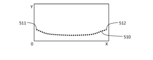
- FIG. 13 is a diagram showing an output of a sensor when there is no article to be conveyed according to the embodiment.
- FIG. 13 is a diagram showing an output of a sensor when an object is present according to the embodiment.
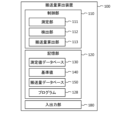
- 2 is a functional block diagram of a transport amount calculation device according to the embodiment.
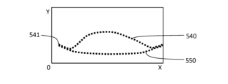
- FIG. 5A to 5C are diagrams for explaining deviation of a belt according to the embodiment. 4 is a diagram for explaining a cross-sectional area of a transported object according to the embodiment;
- FIG. 10 is a flowchart of a transport amount calculation process according to the embodiment.
- the following describes a transport amount calculation device in a form (embodiment) for implementing the present invention.
- Two-dimensional point cloud data acquired by a sensor installed on the belt conveyor is input to the transport amount calculation device.
- the sensor is, for example, LiDAR (Light Detection And Ranging or Laser Imaging Detection and Ranging), and can measure the distance to an object using laser light and acquire the (cross-sectional) shape of the transported object as two-dimensional point cloud data. Note that the cross section is in the width direction (transverse section).
- the conveying amount calculation device calculates the cross-sectional area of the conveyed object by calculating the difference with two-dimensional point cloud data showing the shape of the belt when there is no conveyed object, and then calculates the conveying amount (volume) by multiplying this by the belt speed of the belt conveyor.
- the belt of a belt conveyor can be made of rubber, resin, metal, etc., but unlike roller conveyors, the belt can "deflect” and in some cases “shift left and right.” This will be described later.
- the belt of a conveyor belt may shift left and right (horizontally) relative to the direction of travel.
- the transport amount calculation device detects the belt's shift by detecting the belt's endpoints based on two-dimensional point cloud data, and corrects the two-dimensional point cloud data (point cloud data showing the belt's shape) when there is no transported object, thereby calculating point cloud data showing the shape of the shifted belt and obtaining the cross-sectional area. In this way, the transport amount calculation device can calculate the transport amount with high accuracy even if the belt is shifted.
- ⁇ Overall configuration of the transport amount calculation system> 1 is an overall configuration diagram of a transport amount calculation system 10 according to this embodiment.
- the transport amount calculation system 10 includes a transport amount calculation device 100 and a sensor 200.
- a three-dimensional coordinate system 380 is referred to.
- the Z axis is the traveling direction of a belt conveyor 300 (belt 310)
- the X axis is the horizontal (left-right) direction
- the Y axis is the up-down direction.
- the sensor 200 is installed on the belt conveyor 300, measures the shape of the surface of the object being transported by the belt conveyor 300 as seen from above, and outputs the measurement results, that is, two-dimensional point cloud data, to the transport amount calculation device 100.
- the two-dimensional point cloud data indicates the shape of the surface of the object in the X-Y plane including the sensor 200 (a plane that is parallel to the plane including the X-axis and Y-axis and includes the sensor 200).
- the amount of deflection of the belt 310 increases according to the weight (transport amount) of the transported object.
- the sensor 200 is installed on a portion (support portion 320 supporting the belt 310 from below) where no deflection occurs (the amount of deflection does not change) even if the weight increases, and two-dimensional point cloud data of the cross-sectional shape is acquired. Misalignment data is also acquired.
- ⁇ 2D point cloud data> 2 is a diagram showing an output of the sensor 200 when there is no transported object according to the present embodiment.
- a dotted line 510 indicates a two-dimensional point cloud (two-dimensional point cloud data) corresponding to the surface of the belt 310. End points 511 and 512 of the dotted line 510 indicate the ends of the belt 310.
- 3 is a diagram showing the output of the sensor 200 when an object is present according to this embodiment.
- the dotted line 520 indicates a two-dimensional point cloud corresponding to the surface of the object on the belt 310.
- each point in the two-dimensional point cloud is shown using a coordinate system with the lower left corner as the origin, the lower side as the X-axis, and the left side as the Y-axis.
- the X-axis and Y-axis correspond to the X-axis and Y-axis, respectively, of the three-dimensional coordinate system 380 (see FIG. 1).
- the transport amount calculation device 100 is a computer, and includes a control unit 110, a storage unit 120, and an input/output unit 180.
- User interface devices such as a display, keyboard, and mouse are connected to the input/output unit 180.
- the input/output unit 180 includes a communication device, and is capable of transmitting and receiving data to and from the sensor 200.
- the storage unit 120 includes storage devices such as a read only memory (ROM), a random access memory (RAM), a solid state drive (SSD), etc.
- the storage unit 120 stores a measurement value database 130, a reference value 140, a transport amount database 150, and a program 128.
- the program 128 includes a description of a transport amount calculation process (see FIG. 7) to be described later.
- the measurement value database 130 stores the time series data of the two-dimensional point cloud data acquired from the sensor 200 in association with the acquisition time.
- the two-dimensional point cloud data is acquired, for example, at one-second intervals, and is a collection (group of coordinates) of coordinates of points (X-Y coordinates) that indicate the shape of the surface of the transported object or belt 310.
- the reference value 140 is two-dimensional point cloud data (see FIG. 2) when there is no load, and is a coordinate group of points indicating the dotted line 510. As described later, the reference value 140 is (a coordinate group of) two-dimensional point cloud data indicating the surface of the belt 310 when the belt 310 is not misaligned left or right (in the X-axis direction).
- the transport amount database 150 is time-series data of the calculated transport amounts (transport amounts per unit time).
- the control unit 110 includes a CPU (Central Processing Unit), and is provided with a measurement unit 111 , a detection unit 112 , and a transport amount calculation unit 113 .
- the measurement unit 111 stores the two-dimensional point cloud data, which is the output of the sensor 200, in the measurement value database 130.
- Detection unit The detector 112 detects deviation in the left-right direction (X-axis direction) with respect to the traveling direction (Z-axis direction) of the belt 310.
- Fig. 5 is a diagram for explaining deviation of the belt 310 according to the present embodiment. The position in the X-axis direction of an end point 531 of a dotted line 530 indicating the surface of the belt 310 or the conveyed object is deviated from the position of the end point 511 at the reference value 140 (see Fig. 2).
- This state occurs when belt 310 is misaligned in the positive direction on the X-axis.
- the end of belt 310 on the negative side of the X-axis is detected as end point 531 of dotted line 530.
- Detection unit 112 detects this misalignment of belt 310 and calculates the amount of misalignment.
- the amount of misalignment can be calculated by comparing the X-coordinate of end point 531 with the X-coordinate of end point 511 at reference value 140.
- the conveyance amount calculation device 100 includes the detection unit 112 that calculates the position of the belt 310 in the horizontal direction (X-axis direction) perpendicular to the traveling direction of the belt 310 .
- the detection unit 112 calculates the position of the belt 310 in the horizontal direction (X-axis direction) perpendicular to the traveling direction of the belt 310 based on point cloud data (see end points 531) indicating the end points of the belt 310 contained in the transported item point cloud data (see dotted line 530 in Figure 5).
- the conveyance amount calculation unit 113 calculates the cross-sectional area of the conveyed object, and calculates the conveyance amount by multiplying the cross-sectional area by the belt speed of the belt 310.
- Fig. 6 is a diagram for explaining the cross-sectional area of the conveyed object according to this embodiment.
- a dotted line 540 indicates a two-dimensional point cloud corresponding to the surface of the conveyed object on the belt 310. Note that a left end point 541 of the dotted line 540 is shifted to the right (the positive side of the X-axis) compared to the X-coordinate of the end point 511 at the reference value 140.
- Dotted line 550 is a two-dimensional point cloud obtained by shifting the two-dimensional point cloud indicated by reference value 140 (see dotted line 510) in the X-axis direction in accordance with the position of belt 310 calculated by detection unit 112 based on dotted line 540.
- dotted line 550 indicates a two-dimensional point cloud corresponding to the surface of belt 310 when there is no transported object at the time the two-dimensional point cloud indicated by dotted line 540 is acquired.
- the area sandwiched between dotted lines 510 and 540 then becomes the cross section of the transported object.
- the transport amount calculation unit 113 calculates the area of this cross section and regards it as the cross section of the transported object.
- the conveying amount calculation device 100 includes a conveying amount calculation unit 113 that calculates the cross-sectional area of the conveyed object based on belt point cloud data (see dotted line 550) indicating the shape of the belt 310 of the belt conveyor 300 that conveys the conveyed object, and conveyed object point cloud data (see dotted line 540) indicating the shape of the conveyed object.
- the conveyance amount calculation unit 113 calculates the volume conveyance amount of the conveyed object based on the cross-sectional area and the belt speed of the belt conveyor 300.
- the conveyance amount calculation unit 113 calculates belt point cloud data (see dotted line 550 ) based on the position of the belt 310 .
- the conveying amount calculation unit 113 calculates belt point cloud data (see dotted line 550) based on point cloud data indicating a predetermined belt shape (reference value 140, see dotted line 510) and the belt position calculated by the detection unit 112.
- the method for calculating the cross-sectional area is described below.
- the conveying amount calculation unit 113 regards the dotted lines 510 and 540 as line graphs, calculates the area between the two line graphs, and determines the cross-sectional area.
- the conveying amount calculation unit 113 multiplies the cross-sectional area by the belt speed of the belt 310 to calculate the conveying amount per unit time at the time when the dotted line 540 was obtained.
- the belt speed can be obtained from the control device of the belt conveyor 300.
- the conveyance amount calculation unit 113 may calculate the difference between the average values of the heights (Y coordinate values) of the dotted lines 510 and 540, and multiply this by the width of the belt 310 to obtain the cross-sectional area.
- the width of the belt 310 is the width of the dotted lines 510 and 540 (the length on the X coordinate).
- the conveyance amount calculation unit 113 may calculate the weight conveyance amount by multiplying the conveyance amount by the specific gravity of the conveyed object.
- the specific gravity means the bulk specific gravity (bulk density) in the case of an object having voids therein, such as a powder or granular material.
- the conveying amount calculation unit 113 calculates the area between the polygonal line indicated by the conveyed object point cloud data (see dotted line 540) and the polygonal line indicated by the belt point cloud data (see dotted line 510) as the cross-sectional area.
- the conveying amount calculation unit 113 calculates the cross-sectional area as the product of the difference between the average height calculated from the conveyed item point cloud data (see dotted line 540) and the average height calculated from the belt point cloud data (see dotted line 510) and the width of the belt 310 (the width of dotted lines 510, 540 (length on the X-coordinate)).
- the conveyance amount calculation unit 113 calculates the weight conveyance amount by multiplying the volume conveyance amount by the specific gravity of the object to be conveyed.
- ⁇ Transport amount calculation process> 7 is a flowchart of the transport amount calculation process according to the present embodiment.
- the process in FIG. In step S ⁇ b>11 the measurement unit 111 acquires two-dimensional point cloud data that is the output of the sensor 200 and stores it in the measurement value database 130 .
- step S ⁇ b>12 the detection unit 112 detects the end points of the two-dimensional point cloud indicated by the two-dimensional point cloud data and compares them with the reference value 140 to calculate the deviation of the belt 310 .
- step S13 if the deviation calculated in step S12 is equal to or smaller than a predetermined value, the detection unit 112 determines that there is no deviation (step S13 ⁇ NO) and proceeds to step S15. If the deviation exceeds the predetermined value, the detection unit 112 determines that there is a deviation (step S13 ⁇ YES) and proceeds to step S14.
- step S14 the transport amount calculation unit 113 adjusts the reference value 140.
- the transport amount calculation unit 113 shifts the reference value 140 in the X-axis direction in accordance with the deviation.
- step S15 the transport amount calculation unit 113 calculates a cross-sectional area based on the two-dimensional point cloud (see dotted line 510) of the reference value 140 adjusted in step S14 and the two-dimensional point cloud (see dotted line 540) acquired in step S11.
- step S16 the conveying amount calculation unit 113 multiplies the cross-sectional area calculated in step S15 by the belt speed of the belt 310 to calculate the conveying amount per unit time (volume conveying amount), and stores this in the conveying amount database 150 in association with the acquisition time of the two-dimensional point cloud data (see step S11).
- the conveying amount calculation unit 113 may also multiply the conveying amount per unit time by the specific gravity of the conveyed object to calculate the weight conveying amount per unit time, and store this in the conveying amount database 150 together with the volume conveying amount.
- the conveyance amount calculation device 100 calculates the cross-sectional area of the conveyed object based on a two-dimensional point cloud (see dotted line 540) showing the shape of the conveyed object surface and a two-dimensional point cloud (see dotted line 550) showing the shape of the belt 310 without the conveyed object, and calculates the volume by multiplying it by the belt speed. Furthermore, the conveyance amount calculation device 100 calculates the weight. In this way, the conveyance amount calculation device 100 can calculate the conveyance amount with simpler equipment than the conventional technology.
- the transport amount calculation device 100 also detects the end points of the belt 310, calculates the deviation in the left-right direction (X-axis direction), and adjusts the two-dimensional point cloud (see reference value 140, dotted line 510) that indicates the shape of the belt 310, which is the basis for calculating the cross-sectional area. In this way, the transport amount calculation device 100 can calculate the transport amount with high accuracy even if the belt 310 is misaligned.
- the conveyance amount calculation device 100 calculates the conveyance amount by calculating the cross-sectional area of the conveyed object, but the conveyance amount may be calculated without calculating the cross-sectional area.
- the conveyance amount calculation unit 113 may calculate the conveyance weight using a correlation equation created from the relationship between the average height of the conveyed object calculated from the conveyed object point cloud data (see dotted line 530) and the conveyance weight (weight conveyance amount) measured by another means such as a Merrick belt scale.
- the following linear equation (1) is created from the conveyance weight per unit time measured by the Merrick belt scale and the average value per unit time of the average height of the conveyed object calculated from the conveyed object point cloud data.
- the conveyance amount calculation unit 113 calculates the conveyance weight based on the average height of the conveyed object using the equation (1).
- Transport weight per unit time (average height of transported goods per unit time) x A + B (1)
- the constants A and B in formula (1) are constants that differ depending on the type of transported object and the moving speed of the belt conveyor 300.
- the formula does not need to be a linear formula as long as it can obtain the correlation between the average height and the transported weight of the transported objects. By using such a method, it is possible to calculate the conveyance amount without calculating the cross-sectional area of the conveyed object.
- the conveying amount calculation unit 113 calculates the average height of the transported object based on the transported object point cloud data (see dotted line 530) that indicates the shape of the transported object transported by the belt conveyor 300, and calculates the weight conveying amount or volume conveying amount of the transported object based on the calculated average height using the correlation between the average height of the transported object and the weight conveying amount or volume conveying amount of the transported object (see formula (1)).
- Conveyance amount calculation device 111 Measurement unit 112: Detection unit 113: Conveyance amount calculation unit 128: Program 130: Measurement value database 140: Reference value (point cloud data indicating a preset belt shape) 150 Transport amount database 200 Sensor 300 Belt conveyor 310 Belt 510 Dotted line (point cloud data showing a preset belt shape) 540 Dotted line (transport point cloud data) 550 Dotted line (Belt point cloud data)
Landscapes
- Physics & Mathematics (AREA)
- General Physics & Mathematics (AREA)
- Length Measuring Devices By Optical Means (AREA)
- Control Of Conveyors (AREA)
Abstract
Description
本発明は、このような背景に鑑みてなされたものであり、ベルトコンベアで搬送される搬送物の搬送量の、低コストで高精度な算出を可能とする搬送量算出方法を提供することを課題とする。
なお、ベルトコンベアのベルトは、ゴム製、樹脂製、金属製などがあるが、ローラコンベアなどと異なり、ベルトに「たわみ」や場合によっては「左右方向のずれ」が生じる。この点については、後記する。
図1は、本実施形態に係る搬送量算出システム10の全体構成図である。搬送量算出システム10は、搬送量算出装置100、およびセンサ200を含んで構成される。以下の説明では3次元座標系380を参照する。Z軸はベルトコンベア300(ベルト310)の進行方向であり、X軸は水平(左右)方向、Y軸は上下方向である。
図2は、本実施形態に係る、搬送物がないときのセンサ200の出力を示す図である。点線510は、ベルト310の表面に対応する2次元点群(2次元点群データ)を示す。点線510の端点511,512は、ベルト310の端を示している。
図3は、本実施形態に係る、搬送物があるときのセンサ200の出力を示す図である。点線520は、ベルト310上の搬送物の表面に対応する2次元点群を示す。以下では説明を簡単にするために2次元点群の各点の位置は、左下を原点、下辺をX軸、左辺をY軸とする座標系を用いて示されるものとする。このX軸およびY軸は、3次元座標系380(図1参照)のX軸およびY軸にそれぞれ対応する。
図4は、本実施形態に係る搬送量算出装置100の機能ブロック図である。搬送量算出装置100はコンピュータであり、制御部110、記憶部120、および入出力部180を備える。入出力部180には、ディスプレイやキーボード、マウスなどのユーザインターフェイス機器が接続される。入出力部180が通信デバイスを備え、センサ200とのデータ送受信が可能である。
記憶部120は、ROM(Read Only Memory)やRAM(Random Access Memory)、SSD(Solid State Drive)などの記憶機器を含んで構成される。記憶部120には、測定値データベース130、基準値140、搬送量データベース150、およびプログラム128が記憶される。プログラム128は、後記する搬送量算出処理(図7参照)の記述が含まれる。
搬送量データベース150は、算出された搬送量(単位時間当たりの搬送量)の時系列データである。
制御部110は、CPU(Central Processing Unit)を含んで構成され、測定部111、検出部112、および搬送量算出部113が備わる。
測定部111は、センサ200の出力である2次元点群データを測定値データベース130に格納する。
検出部112は、ベルト310の進行方向(Z軸方向)に対して左右方向(X軸方向)のずれを検出する。図5は、本実施形態に係るベルト310のずれを説明するための図である。ベルト310または搬送物の表面を示す点線530の端点531のX軸方向での位置が、基準値140(図2参照)における端点511の位置からずれている。
検出部112は、搬送物点群データ(図5記載の点線530参照)に含まれるベルト310の端点を示す点群データ(端点531参照)を基に、ベルト310の進行方向と垂直で水平方向(X軸方向)におけるベルト310の位置を算出する。
搬送量算出部113は、搬送物の断面積を算出し、ベルト310のベルト速度を乗じることで搬送量を算出する。図6は、本実施形態に係る搬送物の断面積を説明するための図である。点線540は、ベルト310上の搬送物の表面に対応する2次元点群を示す。なお点線540の左側の端点541は、基準値140における端点511のX座標と比較すると右側(X軸のプラス側)にずれている。
搬送量算出部113は、断面積とベルトコンベア300のベルト速度とを基に搬送物の体積搬送量を算出する。
搬送量算出部113は、予め設定されたベルトの形状を示す点群データ(基準値140、点線510参照)と、検出部112が算出したベルトの位置とを基に、ベルト点群データ(点線550参照)を算出する。
搬送量算出部113は、搬送量に搬送物の比重を乗じて重量搬送量を算出してもよい。なお比重は、粉粒体などのように内部に空隙があるものでは、嵩比重(嵩密度)を意味する。
搬送量算出部113は、搬送物点群データ(点線540参照)から算出される平均の高さと、ベルト点群データ(点線510参照)から算出される平均の高さとの差、および、ベルト310の幅(点線510,540の幅(X座標での長さ))の積を断面積として算出する。
搬送量算出部113は、体積搬送量に、搬送物の比重を乗じて重量搬送量を算出する。
図7は、本実施形態に係る搬送量算出処理のフローチャートである。図7の処理は、センサ200の出力である2次元点群データごとに繰り返される処理である。
ステップS11において測定部111は、センサ200の出力である2次元点群データを取得して測定値データベース130に格納する。
ステップS13において検出部112は、ステップS12で算出したずれが所定値以下であればずれはないと判断し(ステップS13→NO)ステップS15に進む。検出部112は、ずれが所定値超であればずれがあると判断し(ステップS13→YES)ステップS14に進む。
ステップS15において搬送量算出部113は、ステップS14で調整した基準値140の2次元点群(点線510参照)とステップS11で取得した2次元点群(点線540参照)とを基に断面積を算出する。
搬送量算出装置100は、搬送物表面の形状を示す2次元点群(点線540参照)および搬送物がないベルト310の形状を示す2次元点群(点線550参照)を基に搬送物の断面積を算出し、ベルト速度を乗じて体積を算出する。さらに搬送量算出装置100は、重量を算出する。このようにすることで搬送量算出装置100は、従来技術より簡易な設備で搬送量を算出することができる。
上記した実施形態において搬送量算出装置100は、搬送物の断面積を求めて搬送量を算出しているが、断面積を求めることなしに搬送量を算出してもよい。搬送量算出部113は、搬送物点群データ(点線530参照)から算出される搬送物の平均の高さと、例えばメリック式ベルトスケールなど別手段で測定された搬送重量(重量搬送量)との関係から作成された相関式を用いて、搬送重量を算出してもよい。例えば、メリック式ベルトスケールで測定された単位時間当たりの搬送重量、および搬送物点群データから算出される搬送物の平均の高さの単位時間当たりの平均値により、下に示すような一次式である式(1)が作成される。搬送量算出部113は、式(1)を用いて搬送物の平均の高さを基に搬送重量を算出する。
単位時間当たりの搬送重量
=(搬送物の平均の高さの単位時間当たりの平均値)×A+B (1)
このような手法を用いることで、搬送物の断面積を算出することなく、搬送量を算出することも可能である。
以上、本発明のいくつかの実施形態について説明したが、これらの実施形態は、例示に過ぎず、本発明の技術的範囲を限定するものではない。本発明はその他の様々な実施形態を取ることが可能であり、さらに、本発明の要旨を逸脱しない範囲で、省略や置換等種々の変更を行うことができる。これら実施形態やその変形は、本明細書等に記載された発明の範囲や要旨に含まれるとともに、特許請求の範囲に記載された発明とその均等の範囲に含まれる。
111 測定部
112 検出部
113 搬送量算出部
128 プログラム
130 測定値データベース
140 基準値(予め設定されたベルトの形状を示す点群データ)
150 搬送量データベース
200 センサ
300 ベルトコンベア
310 ベルト
510 点線(予め設定されたベルトの形状を示す点群データ)
540 点線(搬送物点群データ)
550 点線(ベルト点群データ)
Claims (7)
- 搬送量算出装置が、
搬送物を搬送するベルトコンベアのベルトの形状を示すベルト点群データと、前記搬送物の形状を示す搬送物点群データとを基に当該搬送物の断面積を算出するステップと、
前記断面積と前記ベルトコンベアのベルト速度とを基に前記搬送物の体積搬送量を算出するステップとを実行する
搬送量算出方法。 - 前記搬送物点群データに含まれる前記ベルトの端点を示す点群データを基に、前記ベルトの進行方向と垂直で水平方向における当該ベルトの位置を算出するステップと、
前記ベルトの位置を基に前記ベルト点群データを算出するステップとを実行する
請求項1に記載の搬送量算出方法。 - 予め設定された前記ベルトの形状を示す点群データと、算出した前記ベルトの位置とを基に、前記ベルト点群データを算出するステップを実行する
請求項2に記載の搬送量算出方法。 - 前記搬送物点群データが示す折れ線と、前記ベルト点群データが示す折れ線との間の面積を前記断面積として算出するステップを実行する
請求項1に記載の搬送量算出方法。 - 前記搬送物点群データから算出される平均の高さと、前記ベルト点群データから算出される平均の高さとの差、および、前記ベルトの幅の積を前記断面積として算出するステップを実行する
請求項1に記載の搬送量算出方法。 - 前記体積搬送量に、前記搬送物の比重を乗じて重量搬送量を算出するステップを実行する
請求項1に記載の搬送量算出方法。 - 搬送量算出装置が、
ベルトコンベアで搬送される搬送物の形状を示す搬送物点群データを基に、当該搬送物の平均の高さを算出するステップと、
前記搬送物の平均の高さと、前記搬送物の重量搬送量または体積搬送量との相関を用いて、算出された平均の高さを基に前記搬送物の重量搬送量または体積搬送量を算出するステップとを実行する
搬送量算出方法。
Priority Applications (3)
| Application Number | Priority Date | Filing Date | Title |
|---|---|---|---|
| AU2024283780A AU2024283780A1 (en) | 2023-06-08 | 2024-05-01 | Method for calculating conveyance amount |
| EP24819063.9A EP4726325A1 (en) | 2023-06-08 | 2024-05-01 | Method for calculating conveyance amount |
| KR1020257042636A KR20260015879A (ko) | 2023-06-08 | 2024-05-01 | 반송량 산출방법 |
Applications Claiming Priority (2)
| Application Number | Priority Date | Filing Date | Title |
|---|---|---|---|
| JP2023-095067 | 2023-06-08 | ||
| JP2023095067A JP2024176502A (ja) | 2023-06-08 | 2023-06-08 | 搬送量算出方法 |
Publications (1)
| Publication Number | Publication Date |
|---|---|
| WO2024252826A1 true WO2024252826A1 (ja) | 2024-12-12 |
Family
ID=93795263
Family Applications (1)
| Application Number | Title | Priority Date | Filing Date |
|---|---|---|---|
| PCT/JP2024/016821 Ceased WO2024252826A1 (ja) | 2023-06-08 | 2024-05-01 | 搬送量算出方法 |
Country Status (6)
| Country | Link |
|---|---|
| EP (1) | EP4726325A1 (ja) |
| JP (1) | JP2024176502A (ja) |
| KR (1) | KR20260015879A (ja) |
| AU (1) | AU2024283780A1 (ja) |
| TW (1) | TWI894990B (ja) |
| WO (1) | WO2024252826A1 (ja) |
Citations (6)
| Publication number | Priority date | Publication date | Assignee | Title |
|---|---|---|---|---|
| JP2002081987A (ja) * | 2000-09-08 | 2002-03-22 | Taisei Corp | ベルトコンベアの積載量測定方法およびその装置 |
| JP2005282265A (ja) * | 2004-03-30 | 2005-10-13 | Ohbayashi Corp | シールド掘進機 |
| JP2016133478A (ja) | 2015-01-22 | 2016-07-25 | 大成建設株式会社 | 体積測定システム |
| JP2018105590A (ja) * | 2016-12-28 | 2018-07-05 | 川崎重工業株式会社 | ごみ焼却設備 |
| CN110926331A (zh) * | 2019-10-28 | 2020-03-27 | 中交第二航务工程局有限公司 | 土压平衡盾构机出渣方量动态测量方法 |
| CN115479637A (zh) * | 2022-09-13 | 2022-12-16 | 北京华能新锐控制技术有限公司 | 一种物料传输的体积流量检测方法 |
Family Cites Families (3)
| Publication number | Priority date | Publication date | Assignee | Title |
|---|---|---|---|---|
| CN112945323A (zh) * | 2019-11-26 | 2021-06-11 | 大唐环境产业集团股份有限公司 | 一种上煤流量检测方法 |
| CN113295226A (zh) * | 2021-05-19 | 2021-08-24 | 中冶南方工程技术有限公司 | 一种皮带输送机流量非接触式测量方法 |
| CN115564738A (zh) * | 2022-10-17 | 2023-01-03 | 国家能源集团宿迁发电有限公司 | 基于主动双目立体视觉的干排渣机渣量检测方法及装置 |
-
2023
- 2023-06-08 JP JP2023095067A patent/JP2024176502A/ja active Pending
-
2024
- 2024-05-01 WO PCT/JP2024/016821 patent/WO2024252826A1/ja not_active Ceased
- 2024-05-01 AU AU2024283780A patent/AU2024283780A1/en active Pending
- 2024-05-01 EP EP24819063.9A patent/EP4726325A1/en active Pending
- 2024-05-01 KR KR1020257042636A patent/KR20260015879A/ko active Pending
- 2024-06-04 TW TW113120590A patent/TWI894990B/zh active
Patent Citations (6)
| Publication number | Priority date | Publication date | Assignee | Title |
|---|---|---|---|---|
| JP2002081987A (ja) * | 2000-09-08 | 2002-03-22 | Taisei Corp | ベルトコンベアの積載量測定方法およびその装置 |
| JP2005282265A (ja) * | 2004-03-30 | 2005-10-13 | Ohbayashi Corp | シールド掘進機 |
| JP2016133478A (ja) | 2015-01-22 | 2016-07-25 | 大成建設株式会社 | 体積測定システム |
| JP2018105590A (ja) * | 2016-12-28 | 2018-07-05 | 川崎重工業株式会社 | ごみ焼却設備 |
| CN110926331A (zh) * | 2019-10-28 | 2020-03-27 | 中交第二航务工程局有限公司 | 土压平衡盾构机出渣方量动态测量方法 |
| CN115479637A (zh) * | 2022-09-13 | 2022-12-16 | 北京华能新锐控制技术有限公司 | 一种物料传输的体积流量检测方法 |
Also Published As
| Publication number | Publication date |
|---|---|
| TW202449356A (zh) | 2024-12-16 |
| EP4726325A1 (en) | 2026-04-15 |
| TWI894990B (zh) | 2025-08-21 |
| AU2024283780A1 (en) | 2025-12-11 |
| KR20260015879A (ko) | 2026-02-03 |
| JP2024176502A (ja) | 2024-12-19 |
Similar Documents
| Publication | Publication Date | Title |
|---|---|---|
| CN103278225B (zh) | 基于图像技术检测的皮带称重装置 | |
| US6603563B1 (en) | Apparatus for determining measurements of an object utilizing negative imaging | |
| EP3040678A1 (en) | Photogrammetry system and photogrammetry method | |
| CN113324483B (zh) | 一种用于中厚板尺寸的测量装置及其测量方法 | |
| EP3591354B1 (en) | Axle-load measuring apparatus and axle-load measuring method | |
| CN108474644A (zh) | 体积估计方法、设备和系统 | |
| CN108036749B (zh) | 一种尺寸测量装置及方法 | |
| CN113281777B (zh) | 一种货物体积动态测量方法及其测量装置 | |
| JP6510246B2 (ja) | 体積測定システム | |
| JP2021025853A (ja) | サイズ測定装置、サイズ測定方法、プログラム | |
| CN114577123A (zh) | 一种包裹体积测量系统及方法 | |
| Li et al. | Online measurement methods for material flow on belt conveyors based on LiDAR | |
| JP2024176502A (ja) | 搬送量算出方法 | |
| CN1474160A (zh) | 一种多截面合成三维形面测量方法 | |
| AU2013237637A1 (en) | Train Wagon 3D Profiler | |
| Heyduk | Laser triangulation in 3-dimensional granulometric analysis | |
| KR100672044B1 (ko) | 자동 박스 치수 측정 장치 | |
| CN104501717B (zh) | 泡货物体体积的动态自适应测量方法 | |
| JP2004144643A (ja) | ベルトコンベア搬送物の搬送量自動計測装置及びその方法並びにベルトコンベアの移動速度測定方法 | |
| JP6757952B2 (ja) | 体積測定システム | |
| KR100441392B1 (ko) | 3차원 영상측정을 통한 중량측정장치 | |
| CN112833983B (zh) | 一种基于激光扫描的煤量检测方法 | |
| KR101328696B1 (ko) | 형상측정장치 및 형상측정방법 | |
| CN116839475A (zh) | 一种输送带料流检测方法和装置 | |
| CN115265370A (zh) | 一种面向航空托盘的多维度检测设备及方法 |
Legal Events
| Date | Code | Title | Description |
|---|---|---|---|
| 121 | Ep: the epo has been informed by wipo that ep was designated in this application |
Ref document number: 24819063 Country of ref document: EP Kind code of ref document: A1 |
|
| WWE | Wipo information: entry into national phase |
Ref document number: AU2024283780 Country of ref document: AU |
|
| WWE | Wipo information: entry into national phase |
Ref document number: 2501008321 Country of ref document: TH |
|
| ENP | Entry into the national phase |
Ref document number: 2024283780 Country of ref document: AU Date of ref document: 20240501 Kind code of ref document: A |
|
| REG | Reference to national code |
Ref country code: BR Ref legal event code: B01A Ref document number: 112025026833 Country of ref document: BR |
|
| ENP | Entry into the national phase |
Ref document number: 1020257042636 Country of ref document: KR Free format text: ST27 STATUS EVENT CODE: A-0-1-A10-A15-NAP-PA0105 (AS PROVIDED BY THE NATIONAL OFFICE) |
|
| WWE | Wipo information: entry into national phase |
Ref document number: 202617001704 Country of ref document: IN |
|
| WWE | Wipo information: entry into national phase |
Ref document number: 2024819063 Country of ref document: EP |
|
| NENP | Non-entry into the national phase |
Ref country code: DE |
|
| ENP | Entry into the national phase |
Ref document number: 2024819063 Country of ref document: EP Effective date: 20260108 |
|
| ENP | Entry into the national phase |
Ref document number: 2024819063 Country of ref document: EP Effective date: 20260108 |
|
| ENP | Entry into the national phase |
Ref document number: 2024819063 Country of ref document: EP Effective date: 20260108 |
|
| ENP | Entry into the national phase |
Ref document number: 2024819063 Country of ref document: EP Effective date: 20260108 |
|
| ENP | Entry into the national phase |
Ref document number: 2024819063 Country of ref document: EP Effective date: 20260108 |
|
| WWP | Wipo information: published in national office |
Ref document number: 2024819063 Country of ref document: EP |