WO2024252745A1 - 燃料電池システム - Google Patents
燃料電池システム Download PDFInfo
- Publication number
- WO2024252745A1 WO2024252745A1 PCT/JP2024/008649 JP2024008649W WO2024252745A1 WO 2024252745 A1 WO2024252745 A1 WO 2024252745A1 JP 2024008649 W JP2024008649 W JP 2024008649W WO 2024252745 A1 WO2024252745 A1 WO 2024252745A1
- Authority
- WO
- WIPO (PCT)
- Prior art keywords
- relay
- battery
- fuel cell
- output
- charging rate
- Prior art date
- Legal status (The legal status is an assumption and is not a legal conclusion. Google has not performed a legal analysis and makes no representation as to the accuracy of the status listed.)
- Ceased
Links
Images

Classifications
-
- Y—GENERAL TAGGING OF NEW TECHNOLOGICAL DEVELOPMENTS; GENERAL TAGGING OF CROSS-SECTIONAL TECHNOLOGIES SPANNING OVER SEVERAL SECTIONS OF THE IPC; TECHNICAL SUBJECTS COVERED BY FORMER USPC CROSS-REFERENCE ART COLLECTIONS [XRACs] AND DIGESTS
- Y02—TECHNOLOGIES OR APPLICATIONS FOR MITIGATION OR ADAPTATION AGAINST CLIMATE CHANGE
- Y02E—REDUCTION OF GREENHOUSE GAS [GHG] EMISSIONS, RELATED TO ENERGY GENERATION, TRANSMISSION OR DISTRIBUTION
- Y02E60/00—Enabling technologies; Technologies with a potential or indirect contribution to GHG emissions mitigation
- Y02E60/30—Hydrogen technology
- Y02E60/50—Fuel cells
Definitions
- the technology disclosed in this specification relates to a fuel cell system that is used as a power source for electric vehicles and the like and is equipped with a fuel cell connected to a load device, and a battery that is provided in a discharge path from the fuel cell to the load device and is connected in parallel to the fuel cell.
- This system comprises a fuel cell, a load device, a first wiring that connects the fuel cell to the load device, a battery, and a second wiring that connects the battery to the first wiring.
- a voltage converter is provided on the first wiring to convert voltage between the terminal voltage of the fuel cell and the voltage on the load device side.
- This disclosed technology was made in consideration of the above circumstances, and its purpose is to provide a simpler and less expensive fuel cell system that enables control of the power supplied to the load device so as not to exceed the upper limit power of the fuel cell and battery without using a voltage converter.
- one aspect of the technology disclosed in this application is a fuel cell system including a fuel cell, a load device, a first power line connecting the fuel cell and the load device, a battery, and a second power line connecting the battery and the first power line, the system including a first relay provided on the first power line for opening and closing the first power line, and a second relay provided on the second power line for opening and closing the second power line.
- the supply of power from the fuel cell to the load device is turned on and off by opening and closing the first relay, and the supply of power from the battery to the load device is turned on and off by opening and closing the second relay. Therefore, by appropriately controlling the opening and closing of the first relay and the second relay, it is possible to supply power to the load device in accordance with the output status of the fuel cell and the battery.
- a relay control means for controlling the opening and closing of the first relay and the second relay in order to limit the upper limit of the fuel cell output and the battery output, and a charging rate monitoring means for monitoring the charging rate of the battery, and the relay control means controls the first relay and the second relay to close when the charging rate of the battery monitored by the charging rate monitoring means is lower than a third predetermined value.
- the relay control means closes the first relay and the second relay, so that the outputs of the fuel cell and the battery are left to their natural state. Therefore, the outputs of the fuel cell and the battery are brought close to the allowable operating ranges.
- the relay control means (i) opens the first relay and the second relay when the monitored charging rate is equal to or greater than a first predetermined value, (ii) opens the first relay and closes the second relay when the monitored charging rate is equal to or greater than a second predetermined value and less than the first predetermined value, (iii) closes the first relay and the second relay when the monitored charging rate is equal to or greater than a third predetermined value and less than the second predetermined value and the load device is braking, and (iv) opens the first relay and closes the second relay when the monitored charging rate is equal to or greater than the third predetermined value and less than the second predetermined value and the load device is regenerating, preferably having a relationship of first predetermined value > second predetermined value > third predetermined value.
- the relay control means opens the first relay and the second relay, so that the output of the fuel cell and the output of the battery are both zero.
- the relay control means opens the first relay and closes the second relay, so that the output of the fuel cell is zero and the output of the battery is uninterrupted.
- the relay control means closes the first relay and the second relay, so that the output of the fuel cell and the output of the battery are both uninterrupted.
- the relay control means opens the first relay and closes the second relay, so that the output of the fuel cell is zero and the output of the battery is uninterrupted. Therefore, by controlling the above (i) to (iv), the fuel cell output and battery output are brought closer to the allowable operating range.
- the relay control means corrects the indicated output value according to the charging rate in order to suppress the indicated output value of the load device.
- the relay control means corrects the instruction output value according to the charging rate in order to suppress the instruction output value of the load device. Therefore, when the charging rate is smaller than the third predetermined value, the supply of power from the fuel cell and the battery to the load device is precisely suppressed according to the charging rate.
- a load output determination means for determining an instruction output value of the load device, and the load output determination means determines the instruction output value by subtracting the reduction output value of the fuel cell and the reduction output value of the battery from the required output value of the load device.
- the load device's command output value is determined according to the fuel cell's output capacity status and the battery's output capacity status at each time.
- the configuration of (1) above makes it possible to control the power supplied to the load device so as not to exceed the upper limit power of the fuel cell and battery without using a voltage converter, thereby providing a simpler and less expensive fuel cell system.
- the configuration (2) above has the effect of the configuration (1) above, and in addition, when the battery charging rate decreases, it is possible to limit the upper limit of the fuel cell output and the battery output.
- the configuration (3) above has the effect of the configuration (2) above, and in addition, it is possible to more precisely limit the upper limits of the fuel cell output and the battery output in response to changes in the battery charging rate.
- the configuration (4) above has the effect of the configurations (2) and (3) above, and in addition, when the battery charging rate drops further, the upper limit of the fuel cell output and the battery output can be more precisely limited.
- the configuration (5) above has the effect of the configuration (14) above, and can also prevent excessive output load from being placed on the fuel cell and battery.
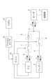
- FIG. 1 is a block diagram showing a fuel cell system mounted on an electric cart according to one embodiment.
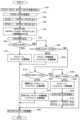
- 5 is a flowchart showing an example of the contents of "power supply control" according to an embodiment.
- 2 is an output correction value map that is referenced to obtain an output correction value according to a charging rate of a battery according to one embodiment.
- FIG. 1 A block diagram of the fuel cell system mounted on an electric cart of this embodiment is shown in Figure 1.
- This fuel cell system includes a fuel cell (FC) 1, an electric motor 2, a first power line 3 connecting the FC 1 and the motor 2, a battery 4, and a second power line 5 connecting the battery 4 and the first power line 3.
- FC fuel cell
- FIG. 1 A block diagram of the fuel cell system mounted on an electric cart of this embodiment is shown in Figure 1.
- This fuel cell system includes a fuel cell (FC) 1, an electric motor 2, a first power line 3 connecting the FC 1 and the motor 2, a battery 4, and a second power line 5 connecting the battery 4 and the first power line 3.
- FC1 is an electrochemical cell that converts the chemical energy of fuel and oxidizer into electricity through an oxidation-reduction reaction, and has a well-known configuration.
- Motor 2 has a well-known configuration and corresponds to an example of a "load device" in this disclosed technology.
- battery 4 is composed of a chargeable and dischargeable secondary battery.
- the first power line 3 is provided in series with a rectifying diode 6 and an FC relay 7 for opening and closing the first power line 3.
- the FC relay 7 corresponds to the "first relay” of this disclosed technology.
- the second power line 5 is connected to the first power line 3 between the diode 6 and the motor 2.
- the second power line 5 is provided with a battery relay 8 for opening and closing the second power line 5.
- the battery relay 8 corresponds to the "second relay" of this disclosed technology.
- the FC relay 7 and the battery relay 8 each have a well-known configuration that can be opened and closed by being electrically operated.
- the fuel cell system further includes an electronic control unit (ECU) 10 for controlling the opening and closing of the relays 7 and 8.
- ECU electronice control unit
- the ECU 10 has a well-known configuration including a central processing unit (CPU) that performs arithmetic processing, a memory, input and output ports, etc.
- the ECU 10 corresponds to an example of a "relay control means" of this disclosed technology.
- the motor 2 is drivingly connected to the driving wheels 11 of the electric cart.
- An accelerator sensor 12 is connected to the ECU 10.
- the accelerator sensor 12 detects the operation angle of a pedal 13 operated by a user of the electric cart as the accelerator opening degree, and outputs the detection signal to the ECU 10.
- the ECU 10 is electrically connected to the battery 4 and is configured to monitor the charging rate SOC of the battery 4.
- the ECU 10 also corresponds to an example of a "charging rate monitoring means" in this disclosed technology.
- the ECU 10 is also electrically connected to the FC1 and the battery 4 and is configured to measure the current and voltage of the FC1 and the current and voltage of the battery 4.
- the ECU 10 also corresponds to an example of a "current and voltage measuring means.”
- the ECU 10 also determines the command output value (motor command output value) of the motor 2, which is the load device, and corresponds to an example of the "load output determination means" of this disclosed technology.
- the ECU 10 executes the following "power supply control" when the electric cart is in operation.
- FIG. 2 is a flowchart showing an example of the contents of the "power supply control" of this embodiment stored in the memory of the ECU 10.
- FIG. 2 is a flowchart showing an example of the contents of the "power supply control" of this embodiment stored in the memory of the ECU 10.
- step 100 the ECU 10 acquires the measured FC1 current value (FC current value) FCCV and voltage value (FC voltage value) FCVV, and the battery 4 current value (battery current value) BTCV and voltage value (battery voltage value) BTVV.
- the ECU 10 calculates the real output value of FC1 (FC real output value) FCRO and the real output value of battery 4 (battery real output value) BTRO.
- the ECU 10 can determine the FC real output value FCRO from the measured FC current value FCCV and FC voltage value FCVV.
- the ECU 10 can also determine the battery real output value BTFCRO from the measured battery current value BTCCV and battery voltage value BTVV.
- step 120 the ECU 10 subtracts the upper limit output value of FC1 (FC upper limit output value) FCUO from the FC real output value FCRO, and sets the result, which is a value equal to or greater than "0", as the reduced output value of FC1 (FC reduced output value) FCDO.
- FC1 FC upper limit output value
- FCUO is a preset value.
- step 130 the ECU 10 subtracts the upper limit output value (battery upper limit output value) BTUO of the battery 4 from the battery real output value BTRO, and sets the result, which is a value equal to or greater than "0", as the reduced output value (battery reduced output value) BTDO of the battery 4.
- the battery upper limit output value BTUO is a preset value.
- step 140 the ECU 10 imposes an upper limit on the command output value (motor command output value) MTCO of the motor 2 by subtracting the FC reduction output value FCDO and the battery reduction output value BTDO from the required output value (motor required output value) MTRO of the motor 2.
- the motor output is limited by the battery output and the FC output.
- step 150 the ECU 10 acquires the charging rate SOC of the battery 4.
- step 160 the ECU 10 determines whether the charging rate SOC is equal to or greater than 80%. "80%" corresponds to an example of the "first predetermined value" in this disclosed technology. If the result of this determination is positive, the ECU 10 proceeds to step 170, and if the result of this determination is negative, the ECU 10 proceeds to step 190.
- step 170 the ECU 10 controls the FC relay 7 and the battery relay 8 to open.
- step 180 the ECU 10 controls the motor 2 using the motor command output value MTCO, and then temporarily ends the subsequent processing.
- step 160 the ECU 10 determines whether the charging rate SOC is equal to or greater than "70%" and less than "80%.” "70%" corresponds to an example of the "second predetermined value" in this disclosed technology. If the result of this determination is positive, the ECU 10 transitions to step 200, and if the result of this determination is negative, the ECU 10 transitions to step 210.
- step 200 the ECU 10 controls the FC relay 7 to be open and the battery relay 8 to be closed, and then proceeds to step 180.
- step 210 the ECU 10 determines whether the charging rate SOC is equal to or greater than "30%" and less than "70%.” "30%” corresponds to an example of the "third predetermined value" (first predetermined value > second predetermined value > third predetermined value) in this disclosed technology. If the result of this determination is positive, the ECU 10 transitions to step 220, and if the result of this determination is negative, the ECU 10 transitions to step 240.
- step 220 the ECU 10 controls the FC relay 7 and the battery relay 8 to be closed while the motor 2 is being braked.
- step 230 the ECU 10 controls the FC relay 7 to be open and the battery relay 8 to be closed while the motor 2 is in regeneration, and then proceeds to step 180.
- step 240 the ECU 10 determines whether the charging rate SOC is less than "30%". If the result of this determination is positive, the ECU 10 proceeds to step 250, and if the result of this determination is negative, the ECU 10 proceeds to step 180.
- step 250 the ECU 10 closes the FC relay 7 and the battery relay 8.
- step 260 the ECU 10 calculates the output correction value KO according to the charging rate SOC.
- the ECU 10 can determine the output correction value KO according to the charging rate SOC by, for example, referring to an output correction value map as shown in FIG. 3.
- step 270 the ECU 10 sets the motor required output value MTRO as the motor command output value MTCO, or sets the result of multiplying the motor command output value MTCO by the output correction value KO as the motor command output value MTCO, and then proceeds to step 180.
- the ECU 10 closes the FC relay 7 and the battery relay 8 when the monitored charging rate SOC of the battery 4 is less than "30%" (third predetermined value) in order to limit the upper limit of the output of the FC 1 and the output of the battery 4.
- the ECU 10 (i) opens the FC relay 7 and the battery relay 8 when the monitored charging rate SOC is equal to or greater than "80%" (first predetermined value), (ii) opens the FC relay 7 and closes the battery relay 8 when the monitored charging rate SOC is equal to or greater than "70%” (second predetermined value) and less than "80%,” (iii) closes the FC relay 7 and the battery relay 8 when the monitored charging rate SOC is equal to or greater than "30%” and less than "70%” and the motor 2 is braking, and (iv) opens the FC relay 7 and closes the battery relay 8 when the monitored charging rate SOC is equal to or greater than "30%” and less than "70%” and the motor 2 is regenerating.
- the ECU 10 corrects the motor command output value MTCO according to the charging rate SOC in order to suppress the motor command output value MTCO of the motor 2.
- the ECU 10 determines the motor command output value MTCO by subtracting the FC power reduction output value FCDO and the battery power reduction output value BTDO from the motor required output value MTOR.
- the ECU 10 closes the FC relay 7 and the battery relay 8, and the outputs of FC1 and battery 4 are left unchanged. Therefore, the outputs of FC1 and battery 4 are brought closer to the allowable range of use. Therefore, when the charging rate SOC of battery 4 decreases, the upper limits of the outputs of FC1 and battery 4 can be limited.
- the ECU 10 opens the FC relay 7 and the battery relay 8, so that the output of FC1 and the output of battery 4 are both zero.
- the ECU 10 opens the FC relay 7 and closes the battery relay 8, so that the output of FC1 is zero and the output of battery 4 remains unchanged.
- the ECU 10 corrects the power requirement value according to the charging rate SOC in order to suppress the power requirement value of the motor 2. Therefore, when the charging rate is less than a third predetermined value, the supply of power from the fuel cell and the battery to the load device (motor command output value MTCO) is precisely suppressed according to the charging rate. Therefore, when the charging rate SOC of the battery 4 decreases further, the upper limit of the output of the FC1 and the output of the battery 4 can be more precisely restricted.
- the ECU 10 determines the motor command output value MTCO by subtracting the FC power reduction output value FCDO and the battery power reduction output value BTDO from the motor required output value MTRO. Therefore, the motor command output value MTCO is determined according to the current output capacity status of FC1 and the output capacity status of the battery 4. This makes it possible to prevent excessive output loads from being placed on FC1 and the battery 4.
- an electric motor 2 is used as the load device, but other electric motors may also be used.
- the disclosed technology can be used in fuel cell systems installed in electric vehicles.
- FC Fluel Cell
- Motor Motor (load device) 3 First power line
- Battery Second power line
- FC relay first relay
- Battery relay second relay
- ECU relay control means, charging rate monitoring means, load output determination means
Landscapes
- Fuel Cell (AREA)
- Electric Propulsion And Braking For Vehicles (AREA)
- Secondary Cells (AREA)
Abstract
Description
図1に、この実施形態の電動カートに搭載された燃料電池システムをブロック図により示す。この燃料電池システムは、燃料電池(FC)1と、電動式のモータ2と、FC1とモータ2を接続する第1電力線3と、バッテリ4と、バッテリ4と第1電力線3を接続する第2電力線5とを備える。
図2に、ECU10のメモリに格納されたこの実施形態の「電力供給制御」の内容の一例をフローチャートにより示す。
以上説明したこの実施形態の燃料電池システムの構成によれば、FCリレー7を開閉することによりFC1からモータ2への電力の供給が入り切りされ、バッテリリレー8を開閉することによりバッテリ4からモータ2への電力の供給が入り切りされる。従って、FCリレー7及びバッテリリレー8の開閉を適宜制御することにより、FC1及びバッテリ4の出力状況に合わせてモータ2への電力供給が可能となる。このため、電圧変換器を使用することなく、FC1とバッテリ4の上限電力を超えないようにモータ2へ供給される電力を制御することができ、簡易でより安価な燃料電池システムを提供することができる。
2 モータ(負荷装置)
3 第1電力線
4 バッテリ
5 第2電力線
7 FCリレー(第1リレー)
8 バッテリリレー(第2リレー)
10 ECU(リレー制御手段、充電率監視手段、負荷出力決定手段)
Claims (5)
- 燃料電池と、
負荷装置と、
前記燃料電池と前記負荷装置を接続する第1電力線と、
バッテリと、
前記バッテリと前記第1電力線を接続する第2電力線と
を備えた燃料電池システムにおいて、
前記第1電力線に設けられ、前記第1電力線を開閉するための第1リレーと、
前記第2電力線に設けられ、前記第2電力線を開閉するための第2リレーと
を備えたことを特徴とする燃料電池システム。 - 請求項1に記載の燃料電池システムにおいて、
前記燃料電池の出力及び前記バッテリの出力の上限を制限するために、前記第1リレーと前記第2リレーの開閉を制御するリレー制御手段と、
前記バッテリの充電率を監視するための充電率監視手段と
を備え、
前記リレー制御手段は、前記充電率監視手段により監視される前記バッテリの充電率が第3所定値より小さい場合に、前記第1リレー及び前記第2リレーを閉制御する
ことを特徴とする燃料電池システム。 - 請求項2に記載の燃料電池システムにおいて、
前記リレー制御手段は、
(i)監視される前記充電率が第1所定値以上となる場合に、前記第1リレー及び前記第2リレーを開制御し、
(ii)監視される前記充電率が第2所定値以上かつ前記第1所定値未満となる場合に、前記第1リレーを開制御すると共に前記第2リレーを閉制御し、
(iii)監視される前記充電率が第3所定値以上かつ前記第2所定値未満となり、前記負荷装置が制動中となる場合に、前記第1リレー及び前記第2リレーを閉制御し、
(iv)監視される前記充電率が第3所定値以上かつ前記第2所定値未満となり、前記負荷装置が回生中となる場合に、前記第1リレーを開制御すると共に前記第2リレーを閉制御し、
前記第1所定値>前記第2所定値>前記第3所定値の関係を有する
ことを特徴とする燃料電池システム。 - 請求項2又は3に記載の燃料電池システムにおいて、
前記リレー制御手段は、監視される前記充電率が前記第3所定値より小さい場合に、前記負荷装置の指示出力値を抑制するために前記充電率に応じて前記指示出力値を補正することを特徴とする燃料電池システム。 - 請求項1に記載の燃料電池システムにおいて、
前記負荷装置の指示出力値を決定するための負荷出力決定手段を備え、
前記負荷出力決定手段は、前記負荷装置の要求出力値から前記燃料電池の減量出力値と前記バッテリの減量出力値を減算することにより前記指示出力値を決定する
ことを特徴とする燃料電池システム。
Priority Applications (1)
| Application Number | Priority Date | Filing Date | Title |
|---|---|---|---|
| CN202480009126.7A CN120604366A (zh) | 2023-06-06 | 2024-03-07 | 燃料电池系统 |
Applications Claiming Priority (2)
| Application Number | Priority Date | Filing Date | Title |
|---|---|---|---|
| JP2023-093193 | 2023-06-06 | ||
| JP2023093193A JP2024175415A (ja) | 2023-06-06 | 2023-06-06 | 燃料電池システム |
Publications (1)
| Publication Number | Publication Date |
|---|---|
| WO2024252745A1 true WO2024252745A1 (ja) | 2024-12-12 |
Family
ID=93795791
Family Applications (1)
| Application Number | Title | Priority Date | Filing Date |
|---|---|---|---|
| PCT/JP2024/008649 Ceased WO2024252745A1 (ja) | 2023-06-06 | 2024-03-07 | 燃料電池システム |
Country Status (3)
| Country | Link |
|---|---|
| JP (1) | JP2024175415A (ja) |
| CN (1) | CN120604366A (ja) |
| WO (1) | WO2024252745A1 (ja) |
Citations (2)
| Publication number | Priority date | Publication date | Assignee | Title |
|---|---|---|---|---|
| JP2013072751A (ja) * | 2011-09-28 | 2013-04-22 | Daihatsu Motor Co Ltd | 絶縁状態判断装置 |
| JP2019125437A (ja) * | 2018-01-12 | 2019-07-25 | トヨタ自動車株式会社 | 燃料電池車 |
-
2023
- 2023-06-06 JP JP2023093193A patent/JP2024175415A/ja active Pending
-
2024
- 2024-03-07 WO PCT/JP2024/008649 patent/WO2024252745A1/ja not_active Ceased
- 2024-03-07 CN CN202480009126.7A patent/CN120604366A/zh active Pending
Patent Citations (2)
| Publication number | Priority date | Publication date | Assignee | Title |
|---|---|---|---|---|
| JP2013072751A (ja) * | 2011-09-28 | 2013-04-22 | Daihatsu Motor Co Ltd | 絶縁状態判断装置 |
| JP2019125437A (ja) * | 2018-01-12 | 2019-07-25 | トヨタ自動車株式会社 | 燃料電池車 |
Also Published As
| Publication number | Publication date |
|---|---|
| CN120604366A (zh) | 2025-09-05 |
| JP2024175415A (ja) | 2024-12-18 |
Similar Documents
| Publication | Publication Date | Title |
|---|---|---|
| JP3687991B2 (ja) | ハイブリッド電源装置 | |
| US10195959B2 (en) | Vehicle power control | |
| US8008801B2 (en) | Vehicle power supply device | |
| US8084151B2 (en) | Fuel cell system and method therefor | |
| EP1270310B1 (en) | Control device for fuel cell vehicle | |
| JP3599773B2 (ja) | ハイブリッド電源装置 | |
| US20120296505A1 (en) | Fuel cell vehicle | |
| JP5145724B2 (ja) | 電力供給システム | |
| US7034475B2 (en) | Control apparatus for controlling regenerative operation of vehicle motor | |
| JP7464006B2 (ja) | 充電システム、充電器、および、充電システムの制御方法 | |
| US9987931B2 (en) | Method of disconnecting secondary battery and electric power supply system | |
| JP7582241B2 (ja) | 二次電池の制御装置、および、二次電池の満充電容量推定方法 | |
| JP2011010508A (ja) | 電源システム | |
| JP4517500B2 (ja) | 燃料電池装置 | |
| JP3185674B2 (ja) | ハイブリッド自動車の発電制御装置 | |
| JP2004180395A (ja) | 蓄電装置の電圧検出線の断線検知装置 | |
| JP4308479B2 (ja) | 燃料電池電源装置 | |
| JP2000166105A (ja) | バッテリ充電状態制御装置 | |
| JP2024175415A (ja) | 燃料電池システム | |
| JP2022029147A (ja) | 電池システム | |
| JP2002231286A (ja) | 燃料電池装置及び燃料電池装置の制御方法 | |
| JP2021082493A (ja) | 燃料電池システム | |
| WO2024252746A1 (ja) | 燃料電池システム | |
| JP3910385B2 (ja) | 燃料電池自動車の制御装置 | |
| JP2001292502A (ja) | ハイブリッド自動車の発電制御装置 |
Legal Events
| Date | Code | Title | Description |
|---|---|---|---|
| 121 | Ep: the epo has been informed by wipo that ep was designated in this application |
Ref document number: 24818984 Country of ref document: EP Kind code of ref document: A1 |
|
| WWE | Wipo information: entry into national phase |
Ref document number: 202480009126.7 Country of ref document: CN |
|
| WWP | Wipo information: published in national office |
Ref document number: 202480009126.7 Country of ref document: CN |
|
| NENP | Non-entry into the national phase |
Ref country code: DE |
|
| 122 | Ep: pct application non-entry in european phase |
Ref document number: 24818984 Country of ref document: EP Kind code of ref document: A1 |