WO2024252704A1 - 保守計画立案支援システム及び設備の保守計画の生成方法 - Google Patents
保守計画立案支援システム及び設備の保守計画の生成方法 Download PDFInfo
- Publication number
- WO2024252704A1 WO2024252704A1 PCT/JP2024/000023 JP2024000023W WO2024252704A1 WO 2024252704 A1 WO2024252704 A1 WO 2024252704A1 JP 2024000023 W JP2024000023 W JP 2024000023W WO 2024252704 A1 WO2024252704 A1 WO 2024252704A1
- Authority
- WO
- WIPO (PCT)
- Prior art keywords
- maintenance
- equipment
- cost
- time
- evaluation value
- Prior art date
- Legal status (The legal status is an assumption and is not a legal conclusion. Google has not performed a legal analysis and makes no representation as to the accuracy of the status listed.)
- Ceased
Links
Images












Classifications
-
- G—PHYSICS
- G06—COMPUTING OR CALCULATING; COUNTING
- G06Q—INFORMATION AND COMMUNICATION TECHNOLOGY [ICT] SPECIALLY ADAPTED FOR ADMINISTRATIVE, COMMERCIAL, FINANCIAL, MANAGERIAL OR SUPERVISORY PURPOSES; SYSTEMS OR METHODS SPECIALLY ADAPTED FOR ADMINISTRATIVE, COMMERCIAL, FINANCIAL, MANAGERIAL OR SUPERVISORY PURPOSES, NOT OTHERWISE PROVIDED FOR
- G06Q10/00—Administration; Management
- G06Q10/04—Forecasting or optimisation specially adapted for administrative or management purposes, e.g. linear programming or "cutting stock problem"
-
- G—PHYSICS
- G06—COMPUTING OR CALCULATING; COUNTING
- G06Q—INFORMATION AND COMMUNICATION TECHNOLOGY [ICT] SPECIALLY ADAPTED FOR ADMINISTRATIVE, COMMERCIAL, FINANCIAL, MANAGERIAL OR SUPERVISORY PURPOSES; SYSTEMS OR METHODS SPECIALLY ADAPTED FOR ADMINISTRATIVE, COMMERCIAL, FINANCIAL, MANAGERIAL OR SUPERVISORY PURPOSES, NOT OTHERWISE PROVIDED FOR
- G06Q10/00—Administration; Management
- G06Q10/20—Administration of product repair or maintenance
-
- G—PHYSICS
- G06—COMPUTING OR CALCULATING; COUNTING
- G06Q—INFORMATION AND COMMUNICATION TECHNOLOGY [ICT] SPECIALLY ADAPTED FOR ADMINISTRATIVE, COMMERCIAL, FINANCIAL, MANAGERIAL OR SUPERVISORY PURPOSES; SYSTEMS OR METHODS SPECIALLY ADAPTED FOR ADMINISTRATIVE, COMMERCIAL, FINANCIAL, MANAGERIAL OR SUPERVISORY PURPOSES, NOT OTHERWISE PROVIDED FOR
- G06Q50/00—Information and communication technology [ICT] specially adapted for implementation of business processes of specific business sectors, e.g. utilities or tourism
- G06Q50/40—Business processes related to the transportation industry
Definitions
- the present invention relates to a system and method that supports the creation of maintenance plans for facilities that consist of multiple devices.
- Mobility operators perform maintenance on vehicle equipment, which is made up of multiple devices, to ensure safety and ensure stable transportation.
- vehicle equipment which is made up of multiple devices, to ensure safety and ensure stable transportation.
- each device in the vehicle equipment is inspected, and if the measurement value obtained during the inspection is greater than a threshold value, or if the device has reached the maintenance deadline, the device is replaced or repaired.
- the threshold value and replacement period for each device are set by the device manufacturer or the mobility operator.
- the series of actions of inspection and replacement or repair will be referred to as maintenance.
- Patent Document 1 and Patent Document 2 are known as technologies for generating maintenance plans.
- Patent Documents 1 and 2 By combining the technologies described in Patent Documents 1 and 2, it is possible to create a maintenance plan that takes risks and costs into account and has minimal violations of constraints. However, if there is a violation of the constraints on resources required to perform equipment maintenance, maintenance will be delayed because sufficient time and space for work cannot be secured.
- the present invention provides technology that supports the creation of maintenance plans that meet resource constraints and minimize maintenance costs.
- a representative example of the invention disclosed in this application is as follows:
- a maintenance plan creation support system that generates a maintenance plan for equipment used in the implementation of a service and consisting of multiple devices, the system includes a processor, a storage device connected to the processor, and a computer having an interface connected to the processor, and is connected to a system that operates the multiple devices, and holds equipment status information for managing the recommended maintenance timing for each of the multiple devices of the equipment, the recommended maintenance timing being a time when the cost required for maintaining the equipment is low and the failure rate of the equipment is low, the processor determines a first constraint condition regarding the probability of a malfunction occurring in the equipment, and a maintenance schedule for the equipment at a time shifted from the recommended maintenance timing,
- a first process generates a plurality of maintenance equipment lists for each piece of equipment as a first optimization problem to search for a maintenance equipment list, which is a combination of the equipment of the equipment to be maintained during the maintenance period, using an evaluation value calculated using the equipment maintenance cost loss that evaluates the economic loss due to maintenance.
- a second process generates a plurality of maintenance plans as a second optimization problem to search for a maintenance plan, which is a combination of the maintenance date and time, the resource allocation, and the maintenance equipment list, for each piece of equipment, using a total evaluation value calculated using the evaluation value and a second constraint condition related to the total probability of malfunction occurrence of the equipment and the resources required to maintain the equipment.
- the present invention makes it possible to devise a maintenance plan that satisfies resource constraints and requires low maintenance costs. Problems, configurations, and advantages other than those described above will become clear from the explanation of the embodiments below.
- FIG. 1 illustrates an example of a configuration of a maintenance plan formulation support system according to a first embodiment.
- FIG. 2 is a diagram illustrating an example of a hardware configuration of a computer that configures the maintenance plan creation support system of the first embodiment.
- FIG. 4 is a diagram illustrating an example of a data structure of service operation information according to the first embodiment.
- FIG. 4 is a diagram illustrating an example of a data structure of track condition information according to the first embodiment.
- FIG. 2 is a diagram illustrating an example of a data structure of vehicle equipment operation information according to the first embodiment.
- FIG. 4 is a diagram illustrating an example of a data structure of device status information according to the first embodiment.
- FIG. 4 is a diagram illustrating an example of a data structure of device specification information according to the first embodiment.
- FIG. 4 is a diagram illustrating an example of a data structure of maintenance work information according to the first embodiment.
- FIG. 11 is a diagram illustrating an example of a data structure of work line information according to the first embodiment.
- FIG. 4 is a diagram illustrating an example of a data structure of worker information according to the first embodiment.
- FIG. 11 is a diagram illustrating an example of a data structure of maintenance deadline information according to the first embodiment.
- FIG. 13 is a diagram illustrating an example of a data structure of maintenance device list information according to the first embodiment.
- FIG. 4 is a diagram illustrating an example of a data structure of maintenance plan information according to the first embodiment.
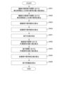
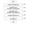
- 1 is a flowchart illustrating a process executed by the maintenance plan formulation support system according to the first embodiment.
- 4 is a flowchart illustrating a traveling load calculation process executed by the maintenance plan formulation support system of the first embodiment.
- 1 is a flowchart illustrating a recommended maintenance period calculation process executed by the maintenance plan formulation support system according to the first embodiment.
- 1 is a flowchart illustrating an optimization process of a maintenance device list executed by the maintenance plan creation support system according to the first embodiment.
- 11 is a flowchart illustrating a maintenance evaluation value calculation process executed by the maintenance plan planning support system of the first embodiment.
- 1 is a flowchart illustrating a maintenance plan optimization process executed by the maintenance plan planning support system according to the first embodiment.
- 11 is a flowchart illustrating a comprehensive evaluation value calculation process executed by the maintenance plan formulation support system according to the first embodiment.
- FIG. 1 is a flowchart illustrating an adjustment process executed by the maintenance plan creation support system according to the first embodiment.
- FIG. 2 is a diagram showing an example of a screen presented by the maintenance plan formulation support system of the first embodiment.
- FIG. 11 is a diagram illustrating an example of a data structure of maintenance device list information according to the second embodiment.
- 13 is a flowchart illustrating a maintenance evaluation value calculation process executed by the maintenance plan planning support system of the second embodiment.
- 13 is a flowchart illustrating a comprehensive evaluation value calculation process executed by the maintenance plan planning support system according to the second embodiment.
- FIG. 11 is a diagram showing an example of a screen presented by the maintenance plan planning support system of the second embodiment.
- a railway business is assumed as an example of a mobility business. Note that the present invention is not limited to the type of mobility business.
- the number of combination patterns to be considered is 2 ⁇ (N x n x P).
- multiple maintenance equipment patterns are generated for each vehicle equipment, and a maintenance equipment pattern for each vehicle equipment is selected at a certain maintenance time.
- C maintenance equipment patterns have been generated for each vehicle
- the number of combination patterns to be considered at a maintenance time is NC.
- the operation of selecting a maintenance equipment pattern for one maintenance time is repeatedly performed. This makes it possible to create a medium- to long-term maintenance plan.
- the optimal maintenance time for the equipment is determined taking into account the maintenance costs and failure characteristics. In other words, it is determined so that both the maintenance costs and the risk of failure are small. Therefore, it is desirable to perform maintenance on the equipment at the optimal maintenance time. However, if a maintenance plan for one maintenance time is repeatedly generated based on risk and cost, it will no longer be possible to maintain each piece of equipment at the optimal maintenance time.
- the method of repeatedly selecting maintenance equipment for each piece of rolling stock equipment based on simple evaluation indices such as risk and cost makes it impossible to maintain each piece of equipment at the optimal maintenance time.
- a railway business uses rolling stock equipment consisting of multiple devices.
- Maintenance of the rolling stock equipment is performed at a rolling stock depot.
- the rolling stock depot has multiple tracks (tracks) on which the rolling stock equipment is maintained.
- Maintenance work at the rolling stock depot is performed by workers. Tracks and workers are treated as resources used for maintenance.
- FIG. 1 is a diagram showing an example of the configuration of a maintenance plan creation support system according to a first embodiment.
- FIG. 2 is a diagram showing an example of the hardware configuration of a computer constituting the maintenance plan creation support system according to a first embodiment.
- the maintenance planning support system 100 is composed of a computer 200 as shown in FIG. 2.
- the number of computers 200 constituting the maintenance planning support system 100 is not limited.
- the computer 200 includes a processor 201, a main memory device 202, an auxiliary memory device 203, an input device 204, a display device 205, and a communication device 206. Each hardware element is connected to each other via a bus.
- the input device 204 is a keyboard, mouse, etc., and accepts input of data and instructions.
- the maintenance work manager operates the input device 204 to instruct the creation of a maintenance plan.
- the maintenance plan creation support system 100 receives the instruction, it creates a maintenance plan that takes into account the risks and costs of the rolling stock equipment, as well as the resources of the rolling stock depot.
- the display device 205 is a display, etc., and displays setting information, processing results, etc.
- the main storage device 202 is a memory or the like, and stores the programs executed by the processor 201 and the data used by the programs.
- the main storage device 202 is also used as a work area.
- the auxiliary storage device 203 is, for example, a HDD (Hard Disk Drive) or the like, and permanently stores programs and information.
- the auxiliary storage device 203 stores programs that realize the maintenance equipment list generation unit 101 and the maintenance plan generation unit 102.
- the auxiliary storage device 203 also stores service operation information 131, track status information 132, rolling stock equipment operation information 133, equipment status information 134, equipment specification information 135, maintenance work information 136, work track information 137, worker information 138, maintenance deadline information 139, maintenance equipment list information 140, and maintenance plan information 141.
- the processor 201 operates as a functional unit (module) that realizes a specific function by executing a program.
- a functional unit module
- the processor 201 is executing a program that realizes the functional unit.
- the communication device 206 communicates with a system that manages vehicle equipment or mobility services.
- FIG. 3 is a diagram showing an example of the data structure of the service operation information 131 in the first embodiment.
- Service operation information 131 is information for managing operation plans for mobility services.
- Service operation information 131 stores entries including an operation plan ID 301, a starting station 302, an ending station 303, a track section ID 304, the number of round trips 305, an operation method 306, and an operation load value 307.
- Operation plan ID 301 is a field that stores the ID of the operation plan.
- Start station 302 is a field that stores the station where the rolling stock equipment is located at the start of the operation plan.
- End station 303 is a field that stores the station where the rolling stock equipment is located at the end of the operation plan.
- Track section ID 304 is a field that stores the ID of the section (track section) on which the rolling stock equipment runs, and is the same field as track section ID 401 described below.
- Number of round trips 305 is a field that stores the number of times the rolling stock equipment makes a round trip on the track section.
- Operation method 306 is a field that stores the operation method of the rolling stock equipment.
- Operation load value 307 is a field that stores a value that represents the load of the operation plan (operation load value).
- the service operation information 131 may be set in advance or obtained from an external source.
- the operation load value 307 stores a value calculated by the maintenance plan creation support system 100.
- FIG. 4 is a diagram showing an example of the data structure of the track condition information 132 in the first embodiment.
- the track condition information 132 is information for managing the condition of a track section.
- the track condition information 132 stores entries including a track section ID 401, a track section 402, a section distance 403, an installation date and time 404, an inspection date and time 405, and a deterioration coefficient 406.
- Track section ID 401 is a field that stores the ID of a track section.
- Track section 402 is a field that stores a track section. For example, a combination of stations is stored as information that represents a track section.
- Section distance 403 is a field that stores the distance of the track section.
- Installation date and time 404 is a field that stores the date and time when the track of the track section was installed.
- Inspection date and time 405 is a field that stores the date and time when the track of the track section was inspected. The inspection date and time 405 stores the most recent inspection date and time.
- Deterioration coefficient 406 is a field that stores a deterioration coefficient that indicates the impact that deterioration of the track of the track section has on the running of vehicle equipment.
- the track condition information 132 may be preset or obtained from an external source.
- FIG. 5 is a diagram showing an example of the data structure of vehicle equipment operation information 133 in Example 1.
- Vehicle equipment operation information 133 is information for managing the operation of vehicle equipment.
- Vehicle equipment operation information 133 stores entries including a vehicle equipment ID 501, a load reduction target 502, and an operation plan 503.
- Vehicle equipment ID 501 is a field that stores the ID of the vehicle equipment.
- Load reduction target 502 is a field that stores a flag used by the maintenance plan planning support system 100. The initial value of load reduction target 502 is set to "none.”
- Operation plan 503 is a field that stores the ID of the operation plan implemented by the vehicle equipment. Operation plan 503 includes columns that indicate date and time, and each column stores the ID of the operation plan.
- Vehicle equipment operation information 133 may be set in advance or obtained from an external source.
- FIG. 6 is a diagram showing an example of the data structure of the device status information 134 in the first embodiment.
- Equipment status information 134 is information for managing the status of equipment of vehicle equipment.
- Equipment status information 134 stores entries including an equipment ID 601, vehicle equipment ID 602, start date and time of use 603, maintenance date and time 604, failure date and time 605, cumulative running load value 606, predicted running load value 607, optimal maintenance date and time 608, start date and time 609, and end date and time 610.
- One entry exists for each combination of equipment and vehicle equipment. Note that the fields included in the entry are merely examples and are not limited to these. It is not necessary to include any of the above-mentioned fields, and it may also include other fields.
- Equipment ID 601 is a field that stores the ID of the vehicle equipment device.
- the equipment ID is composed of the type of equipment and an individual number of the equipment.
- Vehicle equipment ID 602 is the same field as vehicle equipment ID 501.
- the start date and time of use 603 is a field that stores the date and time when use of the device began.
- the maintenance date and time 604 is a field that stores the date and time when maintenance was performed before a breakdown occurred.
- the failure date and time 605 is a field that stores the date and time when the device failed.
- the accumulated running load value 606 is a field that stores the accumulated value of the running load from the date and time of start of use to the present.
- the predicted running load value 607 is a field that stores the predicted value of the running load from the present to the maintenance period.
- Optimal maintenance date and time 608 is a field that stores the optimal date and time for replacing the equipment, which is determined from the perspective of maintenance costs and the risk of failure.
- Start date and time 609 and end date and time 610 are fields that store the start date and time and end date and time of the period during which equipment maintenance is recommended (recommended maintenance period).
- the equipment status information 134 may be set in advance or obtained from an external source.
- the cumulative running load value 606, the predicted running load value 607, the optimal maintenance date and time 608, the start date and time 609, and the end date and time 610 are values calculated by the maintenance plan creation support system 100 and stored.
- FIG. 7 is a diagram showing an example of the data structure of device specification information 135 in the first embodiment.
- the equipment specification information 135 is information for managing equipment specifications.
- the equipment specification information 135 stores entries including an equipment type ID 701, failure loss cost 702, maintenance cost 703, lifespan parameters 704, maintenance function list 705, and maintenance work list 706.
- Equipment type ID 701 is a field that stores an ID that indicates the type of equipment.
- Failure loss cost 702 is a field that stores the economic loss that occurs due to equipment failure.
- Maintenance cost 703 is a field that stores the cost required for equipment maintenance.
- Lifetime parameters 704 are a group of fields that store parameters that represent the lifespan model of the equipment. In this embodiment, parameters of a lifespan model that follows the Weibull distribution are stored.
- the maintenance function list 705 is a field that stores information about functions required for the line where equipment maintenance is performed. In this embodiment, it includes columns that represent functions. Each column is set to either "0", which indicates that the function is not required, or "1", which indicates that the function is required.
- the maintenance work list 706 is a field that stores information about work that needs to be performed in the maintenance of equipment. In this embodiment, it includes columns that represent the work. Each column is set to either "0" indicating that the work does not need to be performed, or "1" indicating that the work needs to be performed.
- the device specification information 135 may be set in advance or obtained from an external source.
- FIG. 8 is a diagram showing an example of the data structure of the maintenance work information 136 in the first embodiment.
- Maintenance work information 136 is information for managing details of maintenance work.
- Maintenance work information 136 stores entries including a maintenance work ID 801, work content 802, work amount 803, parallel work ID 804, and work cost 805.
- Maintenance work ID 801 is a field that stores the ID of the maintenance work.
- Work content 802 is a field that stores the specific content of the maintenance work.
- Work amount 803 is a field that stores the amount of work for the maintenance work. The time required for the maintenance work to be performed is stored in the work amount 803.
- Parallel work ID 804 is a field that stores an ID for managing maintenance work that can be performed in parallel. The same ID is set for maintenance work that can be performed in parallel.
- Work cost 805 is a field that stores the cost of the maintenance work.
- the maintenance work information 136 may be set in advance or obtained from an external source.
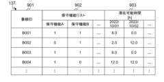
- FIG. 9 is a diagram showing an example of the data structure of the work line information 137 in Example 1.
- Work line information 137 is information for managing work lines.
- Work line information 137 stores entries including a line ID 901, a maintenance function list 902, and possible residence time 903. There is one entry for one work line. Note that the fields included in the entry are merely examples and are not limited to these. An entry may not include any of the above-mentioned fields, and may also include other fields.
- Platform ID 901 is a field that stores the ID of the work platform.
- Maintenance function list 902 is a field that stores information regarding the presence or absence of functions used for equipment maintenance. In this embodiment, it includes columns that represent functions. Each column is set to either "0" indicating that the function is not present, or "1" indicating that the function is present.
- Available residence time 903 is a field that stores the time during which the work platform can be used. Available residence time 903 includes columns that represent date and time, and each column stores the time during which the work platform can be used.
- the work line information 137 may be set in advance or obtained from an external source.
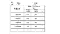
- FIG. 10 is a diagram showing an example of the data structure of worker information 138 in Example 1.
- the worker information 138 is information for managing the workers who perform maintenance work.
- the worker information 138 stores entries including a worker ID 1001 and a work schedule 1002. There is one entry for one worker. Note that the fields included in the entry are merely examples and are not limited to these. An entry may not include any of the above-mentioned fields, and may include other fields.
- Worker ID 1001 is a field that stores the ID of a worker.
- Work schedule 1002 is a field that stores the times when a worker is available to work.
- Work schedule 1002 includes columns that represent dates and times, and each column stores the times when a worker is available to work.
- the worker information 138 may be set in advance or obtained from an external source.
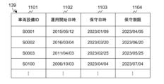
- FIG. 11 is a diagram showing an example of the data structure of the maintenance deadline information 139 in the first embodiment.
- Maintenance deadline information 139 is information for managing the maintenance deadline of vehicle equipment.
- Maintenance deadline information 139 stores entries including a vehicle equipment ID 1101, operation start date and time 1102, maintenance date and time 1103, and maintenance deadline 1104. There is one entry for one piece of vehicle equipment. Note that the fields included in the entry are merely examples and are not limited to these. It is possible for the entry to not include any of the above-mentioned fields, and it may also include other fields.
- Vehicle equipment ID 1101 is the same field as vehicle equipment ID 501.
- Operation start date and time 1102 is a field that stores the date and time when operation of the vehicle equipment started.
- Maintenance date and time 1103 is a field that stores the date and time when maintenance was performed.
- Maintenance date and time 1103 stores the date and time when the most recent maintenance was performed.
- Maintenance deadline 1104 is a field that stores the date and time when maintenance is due to be performed.
- the maintenance deadline information 139 may be set in advance or obtained from an external source.
- FIG. 12 is a diagram showing an example of the data structure of the maintenance device list information 140 in the first embodiment.
- the maintenance equipment list information 140 is information for managing the list of equipment to be maintained, which is generated by the maintenance plan creation support system 100. Multiple maintenance equipment lists may be generated for one piece of vehicle equipment.
- the maintenance equipment list information 140 stores entries including a list ID 1201, a rolling stock equipment ID 1202, a maintenance equipment list 1203, equipment maintenance cost loss 1204, equipment maintenance cost loss 1205, equipment failure rate 1206, equipment maintenance cost 1207, equipment work volume 1208, track residence time 1209, and a maintenance function list 1210.
- a list ID 1201 a rolling stock equipment ID 1202
- a maintenance equipment list 1203 equipment maintenance cost loss 1204
- equipment maintenance cost loss 1205 equipment failure rate 1206, equipment maintenance cost 1207, equipment work volume 1208, track residence time 1209, and a maintenance function list 1210.
- the fields included in the entry are merely examples and are not limited to these. It is possible for the entry to not include any of the above-mentioned fields, and it may also include other fields.
- List ID 1201 is a field that stores the ID of the maintenance equipment list.
- Vehicle equipment ID 1202 is the same field as vehicle equipment ID 501.
- Maintenance equipment list 1203 is a field that stores a list of equipment to be maintained (maintenance equipment). Maintenance equipment list 1203 stores a list of equipment IDs.
- Equipment maintenance cost loss 1204 is a field that stores equipment maintenance cost loss. Details of equipment maintenance cost loss will be described later.
- Equipment maintenance cost loss 1205 is a field that stores equipment maintenance cost loss. Details of equipment maintenance cost loss will be described later.
- Equipment failure rate 1206 is a field that stores the failure rate after maintenance of vehicle equipment.
- Equipment maintenance cost 1207 is a field that stores the cost when all maintenance equipment is maintained.
- Equipment workload 1208 is a field that stores the workload when all maintenance equipment is maintained.
- Platform residence time 1209 is a field that stores the platform residence time when all maintenance equipment is maintained.
- Maintenance function list 1210 is a field that stores a list of maintenance functions required when maintaining all maintenance equipment. In this embodiment, it includes columns that represent functions. Each column is set to either "0" indicating that the function is not required, or "1" indicating that the function is required.
- FIG. 13 is a diagram showing an example of the data structure of the maintenance plan information 141 in the first embodiment.
- the maintenance plan information 141 is information for managing the system maintenance plan generated by the maintenance plan creation support system 100.
- the system maintenance plan is composed of maintenance plans for each piece of rolling stock equipment.
- the maintenance plan information 141 includes a plan ID 1301, rolling stock equipment ID 1302, scheduled maintenance date and time 1303, track ID 1304, list ID 1305, and maintenance evaluation value 1306.
- Plan ID 1301 is a field that stores the ID of the maintenance plan for the rolling stock equipment.
- Rolling stock equipment ID 1302 is a field that stores the ID of the rolling stock equipment to be maintained.
- Planned maintenance date and time 1303 is a field that stores the planned date and time for maintenance.
- Track ID 1304 is a field that stores the ID of the track to be used for maintenance.
- List ID 1305 is a field that stores the ID of the maintenance equipment list.
- Maintenance evaluation value 1306 is a field that stores the maintenance evaluation value.
- FIG. 14 is a flowchart explaining the processing executed by the maintenance plan creation support system 100 of the first embodiment.
- the maintenance plan creation support system 100 receives information about the period for which a maintenance plan is to be generated (planning period), it starts the process described below.
- the maintenance equipment list generation unit 101 receives information regarding the operation and deterioration state of the equipment that constitutes the vehicle equipment, and generates a maintenance equipment list for each vehicle equipment.
- the maintenance equipment list generation unit 101 includes a load calculation unit 111, a recommended maintenance period calculation unit 112, a maintenance equipment list optimization unit 113, and a maintenance evaluation value calculation unit 114.
- the load calculation unit 111 calculates the running load of the vehicle equipment.
- the recommended maintenance period calculation unit 112 calculates the recommended maintenance period of the equipment.
- the maintenance equipment list optimization unit 113 generates a maintenance equipment list for each vehicle equipment based on the first maintenance evaluation value calculated by the maintenance evaluation value calculation unit 114.
- the maintenance evaluation value calculation unit 114 calculates a maintenance evaluation value for evaluating the maintenance equipment list.
- the maintenance plan generation unit 102 receives information on the maintenance equipment list of the rolling stock equipment and resource constraints, and generates a maintenance plan for the rolling stock equipment while satisfying the resource constraints and taking into account risks and costs.
- the maintenance plan for the rolling stock equipment is composed of the rolling stock equipment, the maintenance date and time, the track number, and the maintenance equipment list.
- the maintenance plan generation unit 102 includes a maintenance plan optimization unit 121, an overall evaluation value calculation unit 122, and an adjustment unit 123.
- the maintenance plan optimization unit 121 generates a maintenance plan for each piece of vehicle equipment based on the overall evaluation value calculated by the overall evaluation value calculation unit 122.
- the overall evaluation value calculation unit 122 calculates an overall evaluation value for evaluating the maintenance plan. If a maintenance plan for the system that satisfies the constraints cannot be generated, the adjustment unit 123 adjusts the operation plans between the vehicle equipment.
- the maintenance timing which is the period during which maintenance is performed, is set in the maintenance plan creation support system 100. It is assumed that the maintenance timing is set at regular time intervals.
- the load calculation unit 111 executes a running load calculation process (step S100).
- the recommended maintenance period calculation unit 112 executes a recommended maintenance period calculation process (step S200).
- the maintenance equipment list optimization unit 113 executes a maintenance equipment list optimization process (step S300).
- the maintenance evaluation value calculation unit 114 executes a maintenance evaluation value calculation process (step S400).
- the maintenance plan optimization unit 121 executes a maintenance plan optimization process (step S500).
- the overall evaluation value calculation unit 122 executes an overall evaluation value calculation process (step S600).
- the maintenance plan optimization unit 121 determines whether the constraints are satisfied (step S700).
- the maintenance planning support system 100 ends the series of processes.
- step S800 the adjustment unit 123 executes an adjustment process (step S800). After that, the maintenance plan creation support system 100 returns to step S100 and executes the same process.
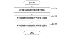
- FIG. 15 is a flowchart explaining the running load calculation process executed by the maintenance plan creation support system 100 of the first embodiment.
- the load calculation unit 111 calculates the operational load value of each operation plan based on the line condition, the operation method, etc. (step S101). Specifically, the following process is executed.
- the load calculation unit 111 selects one operation plan (entry) from the service operation information 131.
- the load calculation unit 111 obtains the value of the round trip count 305 of the operation plan.
- the load calculation unit 111 refers to the line condition information 132 and searches for an entry whose line section ID 401 value matches the line section ID 304 value of the selected operation plan.
- the load calculation unit 111 obtains the values of the section distance 403 and deterioration coefficient 406 of the searched entry.
- the load calculation unit 111 calculates an operational load value by multiplying the number of round trips, the section distance, and the deterioration coefficient.
- the load calculation unit 111 sets the calculated value as the operational load value 307 in the operation plan.
- the load calculation unit 111 determines whether or not processing has been completed for all operation plans. If processing has not been completed for all operation plans, the load calculation unit 111 returns to S101-1. If processing has been completed for all operation plans, the load calculation unit 111 ends the processing of step S101.
- the load calculation unit 111 calculates the predicted running load value of each vehicle facility (step S102). Specifically, the following process is executed.
- the load calculation unit 111 selects one vehicle equipment (entry) from the vehicle equipment operation information 133.
- the load calculation unit 111 obtains an operation plan for the period from the present to the end date and time of the planning period from the operation plan 503 of the entry.
- the load calculation unit 111 references the service operation information 131 based on the ID of the operation plan, and obtains a value from the operation load value 307 of the corresponding entry.
- the load calculation unit 111 calculates the sum of the operational load values of each operation plan as the predicted running load value.
- the load calculation unit 111 references the equipment status information 134 and sets the calculated value to the predicted running load value 607 of all entries in which the ID of the selected vehicle equipment is stored in the vehicle equipment ID 602.
- the load calculation unit 111 determines whether or not processing has been completed for all vehicle equipment. If processing has not been completed for all vehicle equipment, the load calculation unit 111 returns to S102-1. If processing has been completed for all vehicle equipment, the load calculation unit 111 ends the processing of step S102.
- the load calculation unit 111 calculates the cumulative running load value of the equipment for each vehicle facility (step S103). After that, the load calculation unit 111 ends the running load calculation process. Specifically, the following process is executed.
- the load calculation unit 111 selects one vehicle equipment (entry) from the vehicle equipment operation information 133.
- the load calculation unit 111 refers to the equipment status information 134, searches for an entry in which the ID of the selected vehicle equipment is stored in the vehicle equipment ID 602, and generates a list of entry IDs.
- the load calculation unit 111 selects one entry (device) from the list.
- the load calculation unit 111 calculates the operation period of the device.
- the operation period is calculated to be from the date and time stored in the usage start date and time 603 to the current date and time.
- the load calculation unit 111 refers to the operation plan 503 of the entry and identifies the operation plan that was implemented during the operation period.
- the load calculation unit 111 calculates the total value of the operation load values of the identified operation plans as the cumulative running load value.
- the load calculation unit 111 sets the calculated value as the cumulative running load value 606 of the equipment entry.
- the load calculation unit 111 determines whether or not processing has been completed for all entries in the list. If processing has not been completed for all entries in the list, the load calculation unit 111 returns to S103-3.
- the load calculation unit 111 determines whether processing has been completed for all vehicle equipment. If processing has not been completed for all vehicle equipment, the load calculation unit 111 returns to S103-1. When processing has been completed for all vehicle equipment, the load calculation unit 111 ends the processing of step S103.
- the load calculation unit 111 can calculate the cumulative and predicted values of the running load of the equipment that constitutes the rolling stock facility based on the track conditions and the operation plan.
- FIG. 16 is a flowchart explaining the recommended maintenance period calculation process executed by the maintenance plan creation support system 100 of the first embodiment.
- the recommended maintenance period calculation unit 112 selects one vehicle equipment (entry) from the vehicle equipment operation information 133 (step S201).
- the recommended maintenance period calculation unit 112 calculates the failure curve of the selected vehicle equipment device (step S202).
- the distribution of the equipment failure rate is assumed to follow a Weibull distribution. Note that the distribution of the failure rate may follow a statistical distribution other than the Weibull distribution. Details of step S202 are explained below.
- the recommended maintenance period calculation unit 112 refers to the equipment status information 134, searches for an entry in which the ID of the selected vehicle equipment is stored in the vehicle equipment ID 602, and generates a list of entry IDs.
- the recommended maintenance period calculation unit 112 selects one entry (device) from the list.
- the recommended maintenance period calculation unit 112 refers to the equipment specification information 135, obtains the parameters m and ⁇ from the lifespan parameters 704 of the entry corresponding to the selected equipment, and calculates the failure rate curve by substituting them into equation (1).
- i represents the identification number of the equipment
- m_i and ⁇ _i represent the life parameters of the equipment i
- D(t) represents the cumulative running load value during the operation time t
- ⁇ _i represents the failure rate of the equipment i.
- the failure curve is calculated for the running load value.
- t_now represents the operation time (constant) from the date and time when the equipment started operating to the current date and time
- D_now represents the cumulative running load value
- D_fut represents the predicted running load value
- T_insp represents the planning period.
- Equation (2) is a formula that calculates the increase in running load up to the present from the cumulative running load value, and calculates the prediction of the increase in running load thereafter from the predicted running load value.
- the recommended maintenance period calculation unit 112 determines whether or not processing has been completed for all entries in the list. If processing has not been completed for all entries in the list, the recommended maintenance period calculation unit 112 returns to S202-2. If processing has been completed for all entries in the list, the recommended maintenance period calculation unit 112 ends the processing of step S202.
- the recommended maintenance period calculation unit 112 sets potential maintenance periods for each device (step S203). Specifically, the recommended maintenance period calculation unit 112 sets a set of binary variables x_ij as information representing potential maintenance periods for devices.
- the binary variable x_ij is a variable that is "1" when device i is to be maintained in maintenance period j, and is "0" when device i is not to be maintained in maintenance period j.
- the initial potential maintenance periods may be set randomly or according to any rule.
- the recommended maintenance period calculation unit 112 calculates the average failure rate of each piece of equipment when maintenance is performed at the proposed maintenance period (step S204).
- the average failure rate refers to the average failure rate of the equipment from the start to the end of operation.
- the average risk can be estimated from the average failure rate of the equipment.
- the recommended maintenance period calculation unit 112 calculates the average failure rate of the equipment using formula (3).
- T_ij represents the operation time when equipment i is maintained during maintenance period j
- ⁇ _i_ave(T_ij) represents the average failure rate.
- the operation time T_ij is calculated as the time span between the start date and time of use of equipment i and the start date and time of maintenance period j.
- the average failure rate is calculated by assuming that the distribution of the equipment's years of operation is a stationary distribution from the start to the end of operation. Equation (3) does not assume equipment failures during operation, and assumes that the distribution of the time the equipment is used, i.e., the distribution of years of operation, is a stationary distribution up to the time of operation. In reality, equipment may fail during operation, so the average failure rate can also be calculated taking into account that the distribution of years of operation is not a stationary distribution. However, if the equipment failure rate is sufficiently low, changes in the distribution of equipment's years of operation due to failures during operation can be ignored, and it can be approximated by equation (3).
- the recommended maintenance period calculation unit 112 calculates the maintenance cost per unit time for each device (step S205).
- the unit time is one year.
- the recommended maintenance period calculation unit 112 calculates the maintenance cost per unit time using formula (4).
- C_Rep,i represents the maintenance cost of equipment i. Equation (4) does not take into account the labor costs incurred during maintenance and the costs incurred due to equipment failure during the operation period. It is possible to calculate the maintenance cost by taking these factors into account, but if the equipment failure rate is sufficiently low and the labor costs are sufficiently low compared to the equipment maintenance costs, it can be approximated by equation (4).
- the recommended maintenance period calculation unit 112 determines whether the sum of the average failure rates of the devices is smaller than a threshold (constraint condition) and whether the evaluation value calculated using formula (5) has been sufficiently improved (step S206). Note that in the initial processing, the processing of step S206 is not performed and the process returns to step S203.
- step S203 the recommended maintenance period calculation unit 112 sets a potential maintenance time (x_ij) so that the evaluation value calculated using formula (5) becomes small under the constraint conditions shown in formulas (6) and (7).
- ⁇ _st is the upper limit of the average failure rate that is acceptable for the entire facility.
- the upper limit can be set arbitrarily.
- the recommended maintenance period calculation unit 112 determines the optimal maintenance date and time for each device (step S207). Specifically, the recommended maintenance period calculation unit 112 determines the start date and time of the candidate maintenance period to be the optimal maintenance date and time. The recommended maintenance period calculation unit 112 sets the determined optimal maintenance date and time to the optimal maintenance date and time 608 of the device status information 134.
- the series of processes from step S203 to step S207 can be realized by solving a linear optimization problem that searches for the candidate maintenance period x_ij that minimizes the evaluation value calculated using equation (5).
- the recommended maintenance period calculation unit 112 determines the start date and time and the end date and time of the recommended maintenance period for each device (step S208).
- the recommended maintenance period calculation unit 112 uses the equipment failure curve to determine the operation time that is a constant multiple of the failure rate at the optimal maintenance date and time (for example, 0.9 times the lower limit of the tolerance range of the recommended maintenance period), and calculates the start date and time of the recommended maintenance period based on this.
- the recommended maintenance period calculation unit 112 also uses the equipment failure curve to determine the operation time that is a constant multiple of the failure rate at the optimal maintenance date and time (for example, 1.1 times the upper limit of the tolerance range of the recommended maintenance period), and calculates the end date and time of the recommended maintenance period based on this.
- the recommended maintenance period calculation unit 112 sets the calculated dates and times as the start date and time 609 and end date and time 610 of the equipment status information 134.
- the end date and time of the recommended maintenance period for an equipment may be calculated based on a given reliability level that is acceptable for the equipment's failure rate, and the operation time at which the reliability level is no longer met based on the equipment's failure curve.
- the recommended maintenance period calculation unit 112 determines whether processing has been completed for all vehicle equipment (step S209).
- the recommended maintenance period calculation unit 112 returns to step S201. If processing has been completed for all vehicle equipment, the recommended maintenance period calculation unit 112 ends the recommended maintenance period calculation process.
- the recommended maintenance period determined by the above process is a period that strikes a good balance between maintenance costs (costs) and failure rates (risks). Therefore, performing maintenance on equipment within the recommended maintenance period can keep maintenance costs and failure rates low. On the other hand, performing maintenance on equipment outside the recommended maintenance period will result in either maintenance costs or failure rates increasing.
- FIG. 17 is a flowchart explaining the optimization process of the maintenance equipment list executed by the maintenance plan creation support system 100 of the first embodiment.
- FIG. 18 is a flowchart explaining the maintenance evaluation value calculation process executed by the maintenance plan creation support system 100 of the first embodiment.
- the maintenance device list optimization unit 113 executes the process described below for the maintenance period that is closest to the current date and time.
- the closest maintenance period will be referred to as the target maintenance period.
- the maintenance equipment list optimization unit 113 selects one vehicle equipment (entry) from the vehicle equipment operation information 133 (step S301).
- the maintenance equipment list optimization unit 113 sets the optimization conditions (step S302).
- the optimization conditions are constraint conditions used in the optimization problem described below.
- the constraint conditions for available track platforms and the failure rate of rolling stock equipment are set.
- the constraint conditions for available track platforms, the failure rate of rolling stock equipment, the amount of work, and the stay time at the track platform are set.
- a linear optimization problem will be used as an example for explanation.
- the maintenance equipment list optimization unit 113 generates a maintenance equipment list for the selected vehicle equipment (step S303). Specifically, the maintenance equipment list optimization unit 113 generates a set of binary variables x_i as the maintenance equipment list for the vehicle equipment.
- the binary variable x_i is a variable that is "1" when equipment i is maintained and is "0" when equipment i is not maintained.
- the initial vehicle equipment maintenance equipment list is set randomly, for example, according to the rules above.
- the maintenance equipment list optimization unit 113 instructs the maintenance evaluation value calculation unit 114 to execute the maintenance evaluation value calculation process (step S304). At this time, the maintenance equipment list optimization unit 113 inputs the maintenance equipment list to the maintenance evaluation value calculation unit 114.
- the maintenance evaluation value calculation process will be explained using FIG. 18.
- the maintenance evaluation value calculation unit 114 calculates the minimum maintenance cost per unit time during the recommended maintenance period for each device (step S401).
- the value calculated in step S401 is defined as the minimum cost.
- the maintenance cost per unit time for device i can be calculated using equation (8), which has the same format as equation (4).
- T_i represents the operation time when the device i is maintained at any date and time during the recommended maintenance period.
- T_i is a variable that changes depending on the maintenance date and time.
- the maintenance date and time changes within the recommended maintenance period.
- the recommended maintenance period for the device can be calculated based on the start date and time 609 and end date and time 610 of the device status information 134.
- the maintenance evaluation value calculation unit 114 calculates the maintenance cost per unit time for each device when maintenance is performed during the target maintenance period (step S402).
- the cost calculated in step S402 is defined as the comparative cost.
- the maintenance cost per unit time can be calculated using formula (8). Note that T_i is the time (constant) from the operation start date and time to the start date and time of the target maintenance period.
- the maintenance evaluation value calculation unit 114 calculates the difference between the comparison cost and the minimum cost for each piece of equipment as the equipment maintenance cost loss (step S403).
- the equipment maintenance cost loss is calculated using formula (9).
- AC_(Rep-now,i) represents the comparative cost
- AC_(Rep-min,i) represents the minimum cost
- ⁇ AC_(Rep,i) represents the equipment maintenance cost loss.
- the cost loss due to the discrepancy between the recommended maintenance period and the target maintenance period is calculated as the difference in the maintenance cost per unit time.
- the maintenance cost per unit time is a value that depends on the maintenance period, and can be compared between different maintenance periods.
- the maintenance evaluation value calculation unit 114 calculates the total equipment maintenance cost loss for each piece of equipment as the equipment maintenance cost loss (step S404).
- the equipment maintenance cost loss is calculated using formula (10).
- ⁇ AC_Rep represents the equipment maintenance cost loss.
- the maintenance evaluation value calculation unit 114 calculates the maintenance evaluation value using the equipment maintenance cost loss (step S405).
- the equipment maintenance cost loss is calculated as the maintenance evaluation value.
- the maintenance evaluation value is represented as ⁇ AC_Vehi.
- the minimum cost and the comparative cost are both maintenance costs per unit time, and are values on the same scale that are not dependent on the length of the maintenance period. Therefore, the equipment maintenance cost loss can be used as an index for estimating the economic loss when the date and time of maintenance for each piece of equipment deviates from the recommended maintenance period.
- the equipment maintenance priority can be determined by determining which equipment will be maintained so that more equipment is maintained within the recommended maintenance period, i.e., so that the maintenance evaluation value is smaller.
- the maintenance evaluation value calculation unit 114 outputs the maintenance evaluation value to the maintenance equipment list optimization unit 113 and ends the maintenance evaluation value calculation process.
- the maintenance equipment list optimization unit 113 calculates the amount of equipment work required for maintenance (step S305). Specifically, the following process is executed.
- the maintenance equipment list optimization unit 113 refers to the equipment specification information 135 and obtains the maintenance work list 706 of the entries corresponding to all equipment of the vehicle equipment.
- the maintenance equipment list optimization unit 113 defines the maintenance work j to be performed on equipment i as shown in equation (11).
- u_j is a binary variable that is "1" if maintenance work j is performed and is "0" if maintenance work j is not performed.
- u_ij represents the value of maintenance task j in the maintenance task list 706 for the entry corresponding to device i.
- the maintenance equipment list optimization unit 113 calculates the total amount of maintenance work for each piece of equipment in the vehicle equipment as the equipment work amount. Specifically, the equipment work amount is calculated using formula (12).
- W_Vehi represents the amount of equipment work
- w_j represents the amount of work for maintenance work j.
- the amount of work for maintenance work j is a value obtained from the amount of work 803 in the maintenance work information 136.
- the maintenance device list optimization unit 113 calculates the track stay time when performing maintenance (step S306). Specifically, the following process is executed.
- the maintenance device list optimization unit 113 defines the maintenance task j to be performed on device i as shown in formula (11).
- the maintenance equipment list optimization unit 113 calculates the platform dwell time based on the workload of maintenance task j. For maintenance task groups executed in parallel, the maximum workload of each maintenance task can be calculated as the workload of the maintenance task group. Therefore, the platform dwell time can be calculated as the sum of the workloads of the maintenance task groups, as shown in formula (13).
- R_Vehi represents the track dwell time
- k represents the parallel work ID
- U_k represents the set of maintenance work with parallel work ID k.
- the maintenance equipment list optimization unit 113 identifies a work track where maintenance of the rolling stock equipment can be performed (step S307). Specifically, the following process is executed.
- the maintenance equipment list optimization unit 113 refers to the equipment specification information 135 and obtains the maintenance function list 705 of the entries corresponding to all equipment of the vehicle equipment.
- the maintenance equipment list optimization unit 113 uses formula (14) to identify the work functions required for maintaining the vehicle equipment.
- l represents a maintenance function.
- v_il represents the value of function l in the maintenance function list 705 of equipment i.
- v_l is a binary variable indicating whether or not maintenance function l is necessary. If the maintenance function is not necessary, it takes “0", and if the maintenance function is necessary, it takes "1".
- E is a set of equipment that constitutes the vehicle equipment. If maintenance function l is necessary for at least one piece of equipment, the value of equation (14) is 1.
- the maintenance equipment list optimization unit 113 refers to the maintenance function list 902 of each entry in the work line information 137, and identifies the lines where all maintenance functions for which v_l is 1 are set to 1.
- the maintenance equipment list optimization unit 113 saves the processing results as a set of binary variables H_s.
- s represents the work line.
- the binary variable H_s is a variable that is "1" if maintenance can be performed at work line s, and is "0" if maintenance cannot be performed at work line s.
- the maintenance equipment list optimization unit 113 calculates the probability that any of the equipment constituting the vehicle equipment will fail as the equipment failure rate (step S308). Specifically, the following process is executed.
- the maintenance equipment list optimization unit 113 uses formula (15) to calculate the equipment failure probability P_i for each equipment when the equipment is not maintained at the maintenance time.
- the maintenance equipment list optimization unit 113 also uses formula (16) to calculate the equipment failure probability P'_i for each equipment when the equipment is maintained at the maintenance time.
- D_now represents the accumulated running load value
- D_fut represents the predicted running load value
- the accumulated running load value and the predicted running load value are the values of the accumulated running load value 606 and the predicted running load value 607 in the equipment status information 134.
- the parameters of the failure rate curve are the values of the lifespan parameters 704 in the equipment specification information 135.
- the maintenance equipment list optimization unit 113 calculates the equipment failure rate P_Vehi using formula (17).
- the maintenance equipment list optimization unit 113 calculates the maintenance cost C_R of the vehicle equipment (step S309). Specifically, the maintenance equipment list optimization unit 113 calculates the maintenance cost of the vehicle equipment using formula (18).
- the maintenance device list optimization unit 113 determines whether the constraint conditions are satisfied and whether the evaluation value ⁇ AC_Part calculated using equation (19) has been sufficiently improved (step S310). Note that in the first processing for device i, the processing of step S310 is not performed and the process returns to step S303.
- ⁇ represents the workload adjustment coefficient.
- the constraints are given by equations (20), (21), (22), and (23).
- H_(s_st) represents the upper limit of the available line number
- P_(Vehi_st) represents the upper limit of the equipment failure rate
- t_start,i represents the start date and time of the recommended maintenance period for equipment i
- t_end,i represents the end date and time of the recommended maintenance period for equipment i.
- t represents the start date and time of the maintenance period.
- step S303 the maintenance equipment list optimization unit 113 sets the maintenance equipment list so as to reduce the evaluation value ⁇ AC_Part under the constraint conditions shown in formulas (20), (21), (22), and (23).
- the facility work volume included in the evaluation value ⁇ AC_Part is not linear with respect to the maintenance equipment list, but a function defined as the sum of functions including absolute values or "max" can be expressed as the sum of a linear objective function and linear constraint conditions by transforming the equation.
- the optimization problem based on the evaluation value ⁇ AC_Part can be expressed as a mixed integer linear programming problem, and methods such as the branch and bound method can be applied.
- a heuristic optimization method may be used to search for the maintenance equipment list.
- constraints can also be set for the equipment workload and platform stay time, which are not linear to the maintenance equipment list.
- the maintenance evaluation value ⁇ AC_Vehi is used as the evaluation value. That is, using the recommended maintenance end date and time, workload adjustment coefficient, available platform, upper limit of equipment negotiation probability, upper limit of equipment workload, and upper limit of platform stay time, a search is made for a maintenance equipment list that minimizes the maintenance evaluation value ⁇ AC_Vehi under the constraints of Equations (20), (21), (22), (23), (24), and (25).
- step S311 the maintenance equipment list optimization unit 113 registers the maintenance equipment list in the maintenance equipment list information 140 (step S311).
- the series of processes from step S303 to step S311 can be implemented by solving an optimization problem that searches for the maintenance equipment list x_i that minimizes the evaluation value ⁇ AC_Part.
- the maintenance device list optimization unit 113 determines whether or not to set new optimization conditions (step S312). For example, if the number of maintenance device lists generated is equal to or greater than a certain number, or if processing has been performed for all settable optimization conditions, the maintenance device list optimization unit 113 does not set new optimization conditions.
- the maintenance device list optimization unit 113 returns to step S302.
- the maintenance equipment list optimization unit 113 determines whether processing has been performed for all vehicle equipment (step S313).
- the maintenance equipment list optimization unit 113 returns to step S301. If processing has been performed for all equipment, the maintenance equipment list optimization unit 113 ends the optimization processing of the maintenance equipment list.
- FIG. 19 is a flowchart explaining the maintenance plan optimization process executed by the maintenance plan planning support system 100 of the first embodiment.
- FIG. 20 is a flowchart explaining the overall evaluation value calculation process executed by the maintenance plan planning support system 100 of the first embodiment.
- the maintenance plan optimization unit 121 executes the process described below for the maintenance period (target maintenance period) that is closest to the current date and time.
- the maintenance plan optimization unit 121 calculates the available work time and available stay time at the work line for each inspection date and time (step S501).
- the maintenance plan optimization unit 121 generates a maintenance plan for the system (step S502).
- the system maintenance plan is expressed as a set of binary variables y_pqrs (maintenance plan for rolling stock equipment) that indicate whether maintenance will be performed on track s at inspection date and time r for rolling stock equipment p according to maintenance equipment list q.
- the system maintenance plan is generated under the condition that maintenance is performed only once for all rolling stock equipment during the target maintenance period. Note that the inspection date and time represent a date and time within the target maintenance period.
- the maintenance plan optimization unit 121 instructs the overall evaluation value calculation unit 122 to execute the overall evaluation value calculation process (step S503). At this time, the maintenance plan optimization unit 121 inputs the system's maintenance plan to the overall evaluation value calculation unit 122.
- the overall evaluation value calculation process will be explained using FIG. 20.
- the overall evaluation value calculation unit 122 refers to the maintenance equipment list information 140 and obtains the maintenance evaluation value ⁇ AC_Vehi for each piece of vehicle equipment (step S601).
- the overall evaluation value calculation unit 122 calculates the overall evaluation value using the maintenance evaluation value ⁇ AC_Vehi (step S602). Specifically, the overall evaluation value calculation unit 122 calculates the overall evaluation value using formula (26).
- ⁇ AC_All represents the overall evaluation value
- ⁇ AC_Vehi,pq represent the maintenance evaluation value when maintenance is performed on equipment p according to maintenance equipment list q.
- the maintenance evaluation value is the maintenance evaluation value 1306 in the maintenance plan information 141.
- the overall evaluation value calculation unit 122 outputs the overall evaluation value to the maintenance plan optimization unit 121 and ends the overall evaluation value calculation process.
- the maintenance plan optimization unit 121 calculates the sum of the equipment failure probabilities in the system's maintenance plan (step S504). Specifically, the maintenance plan optimization unit 121 calculates the sum of the equipment failure probabilities in the system's maintenance plan using formula (27).
- P_All represents the total vehicle equipment failure rate
- P_Vehi, pq represent the equipment failure rate when maintenance is performed on equipment p according to maintenance equipment list q
- P_Vehi, pq is the value of the equipment failure rate 1206 of an entry whose vehicle equipment ID 1202 and maintenance equipment list 1203 in the maintenance equipment list information 140 match the maintenance equipment list q of equipment p.
- the maintenance plan optimization unit 121 calculates the total amount of equipment work at the maintenance date and time r (step S505). Specifically, the maintenance plan optimization unit 121 calculates the total amount of equipment work at the maintenance date and time r using formula (28).
- W_(All, r) represents the total amount of equipment work at maintenance date and time r
- W_Vehi,pq represents the amount of equipment work when maintenance is performed on equipment p according to maintenance equipment list q
- W_Vehi,pq is the value of the equipment work amount 1208 of an entry whose vehicle equipment ID 1202 and maintenance equipment list 1203 in the maintenance equipment list information 140 match the maintenance equipment list q of equipment p.
- the maintenance plan optimization unit 121 calculates the stay time on track s for each maintenance date and time (step S506). Specifically, the maintenance plan optimization unit 121 calculates the stay time on track s for maintenance date and time r using formula (29).
- R_(ALL,rs) represents the stay time at platform s on maintenance date and time r
- R_Vehi,pq represents the stay time at platform when maintenance is performed on equipment p according to maintenance equipment list q
- R_Vehi,pq is the value of platform stay time 1209 of an entry whose vehicle equipment ID 1202 and maintenance equipment list 1203 in the maintenance equipment list information 140 match the maintenance equipment list q of equipment p.
- step S507 the maintenance plan optimization unit 121 determines whether the constraint conditions are satisfied. Note that in the first processing, the processing of step S507 is not performed and the process returns to step S502.
- P_(All_st) represents the upper limit of the total equipment failure probability and is set in advance.
- W_(All_st) r represents the upper limit of the available work time at the maintenance date and time r and is the available work time calculated in step S501.
- N represents the number of vehicle equipment.
- H_pqs is a binary variable that represents whether maintenance of equipment p according to the maintenance equipment list q can be performed at the work line s. This variable is "1" if maintenance can be performed and "0" if maintenance cannot be performed.
- R_ ⁇ (All_st), rs ⁇ represents the upper limit of the available stay time at the work line s at the inspection date and time r and is the available stay time calculated in step S501.
- t(r) represents the specific date and time of the inspection date and time r.
- p represents the maintenance deadline date and time of the vehicle equipment and is the value of the maintenance deadline 1104 of the maintenance deadline information 139.
- the maintenance plan optimization unit 121 outputs a message indicating that a maintenance plan for the system that satisfies the constraint conditions cannot be generated, and ends the process.
- the maintenance plan optimization unit 121 determines whether the overall evaluation value ⁇ AC_All has been sufficiently improved (step S508).
- step S502 the maintenance plan optimization unit 121 sets a maintenance plan for the system so as to reduce the overall evaluation value under the constraints shown in formulas (30), (31), (32), (33), (34), and (35).
- the maintenance plan optimization unit 121 registers the system's maintenance plan in the maintenance plan information 141 (step S509), and then ends the process.
- the series of processes from step S502 to step S509 can be implemented by solving a linear optimization problem that searches for the system's maintenance plan y_pqrs that minimizes the overall evaluation value.
- FIG. 21 is a flowchart explaining the adjustment process executed by the maintenance plan creation support system 100 of the first embodiment.
- the adjustment unit 123 selects vehicle equipment that reduces the driving load (step S801). Specifically, the following process is executed.
- the adjustment unit 123 refers to the vehicle equipment operation information 133 and identifies vehicle equipment for which the load reduction target 502 is "none.”
- the adjustment unit 123 selects one vehicle equipment from the identified vehicle equipment. For example, the adjustment unit 123 selects vehicle equipment in ascending order of operation start date and time. This is because vehicle equipment with an older operation start date and time deteriorates more quickly in response to a driving load than vehicle equipment with a newer operation start date and time, and therefore it is necessary to reduce the driving load.
- the adjustment unit 123 refers to the service operation information 131 and the vehicle equipment operation information 133 to select one operation plan to be implemented by the selected vehicle equipment during the maintenance period (step S802).
- the operation plans are selected in the order of implementation.
- the adjustment unit 123 determines whether there is any rolling stock equipment that implements an operation plan (similar operation plan) that has the same combination of start and end stations as the selected operation plan during the maintenance period (step S803).
- step S806 If no vehicle equipment exists, the adjustment unit 123 proceeds to step S806.
- the adjustment unit 123 identifies, from the identified vehicle equipment, the vehicle equipment with the smallest operational load value of the similar operation plan (step S804).
- the operational load value can be obtained from the operational load value 307 of the service operation information 131.
- the adjustment unit 123 replaces the selected operation plan of the selected vehicle equipment with a similar operation plan of the identified vehicle equipment (step S805). Specifically, the operation plan 503 of the vehicle equipment operation information 133 is updated.
- the adjustment unit 123 determines whether processing has been performed for all operation plans implemented by the selected vehicle equipment during the maintenance period (step S806).
- step S802 If processing has not been performed for all operation plans implemented by the selected vehicle equipment during the maintenance period, the adjustment unit 123 returns to step S802.
- the adjustment unit 123 When processing has been performed for all operation plans implemented by the selected vehicle equipment during the maintenance period, the adjustment unit 123 refers to the vehicle equipment operation information 133, updates the load reduction target 502 of the entry corresponding to the selected vehicle equipment to "Yes" (step S807), and then terminates the processing.
- the running load of the selected rolling stock equipment is reduced, so the cost of maintaining the rolling stock equipment in the entire system is reduced.
- the equipment failure curve also changes.
- FIG. 22 is a diagram showing an example of a screen presented by the maintenance plan creation support system 100 of the first embodiment.
- the screen 2200 includes a parameter input field 2201, a maintenance plan output field 2202, a maintenance equipment list output field 2203, and an evaluation value output field 2204.
- the maintenance work manager sets parameters in the parameter input field 2201 and instructs the start of processing.
- the maintenance plan planning support system 100 executes various processes and outputs the processing results to the maintenance plan output field 2202, the maintenance equipment list output field 2203, and the evaluation value output field 2204.
- the parameter input field 2201 is a field for setting parameters required for creating a maintenance plan.
- the parameters are, for example, the average failure rate ⁇ _st of the entire equipment set as a risk tolerance, the tolerance range of the recommended maintenance period, the statutory maintenance cycle, the tolerance value P_All_st of the failure probability of all equipment, etc.
- the maintenance plan output field 2202 is a field that displays the system's maintenance plan.
- the system's maintenance plan is displayed as a matrix with inspection dates and times as rows and work lines as columns.
- the elements of the matrix store the IDs of the maintenance equipment list.
- the maintenance plan output field 2202 is provided with a check field for selecting the maintenance plan for the vehicle equipment for which the maintenance equipment list is displayed.
- the maintenance equipment list output field 2203 is a field that displays the maintenance equipment list of the maintenance plan for the vehicle equipment selected in the maintenance plan output field 2202.
- the maintenance equipment list output field 2203 may also display equipment maintenance costs, etc.
- the evaluation value output field 2204 is a field that displays the evaluation value of the maintenance plan for the vehicle equipment selected in the maintenance plan output field 2202. For example, the maintenance evaluation value and the overall evaluation value are displayed in the evaluation value output field 2204.
- the evaluation value output field 2204 may also display the number of days until the end date and time of the recommended maintenance period for the equipment to be maintained. This number of days is the number of days from the end date and time of the recommended maintenance period to the scheduled date and time of maintenance for the vehicle equipment.
- the first embodiment it is possible to generate a system maintenance plan that satisfies the constraints and minimizes the maintenance costs.
- a system maintenance plan that performs maintenance at appropriate times from a medium- to long-term perspective.
- Example 2 differs from Example 1 in that it takes into consideration the effect of reducing maintenance costs when multiple devices are maintained simultaneously. Also, in Example 2, a system maintenance plan is created so that the inspection intervals for vehicle equipment are as long as possible within the statutory maintenance cycle. Example 2 will be explained below, focusing on the differences from Example 1.
- Example 2 The configuration of the maintenance plan planning support system 100 in Example 2 is the same as that in Example 1. In Example 2, the calculation method of the maintenance evaluation value and the overall evaluation value is different. In Example 2, the maintenance equipment list information 140 is different from that in Example 1.
- FIG. 23 is a diagram showing an example of the data structure of the maintenance equipment list information 140 in Example 2.
- Example 2 the maintenance equipment list information 140 newly includes an equipment maintenance cost correction value 1251.
- FIG. 24 is a flowchart explaining the maintenance evaluation value calculation process executed by the maintenance plan planning support system 100 of the second embodiment.
- Example 1 in order to generate a vehicle equipment maintenance plan for maintaining equipment at the recommended maintenance period, a maintenance evaluation value is calculated using the equipment maintenance cost loss ⁇ AC_Rep.
- Example 2 an equipment maintenance cost correction value is introduced to evaluate the effect of reducing maintenance costs when multiple pieces of equipment are maintained simultaneously during maintenance. Furthermore, a maintenance evaluation value is calculated using the equipment maintenance cost loss and the equipment maintenance cost correction value.
- step S4 The processing from step S401 to step S404 is the same as in Example 1.
- the maintenance evaluation value calculation unit 114 identifies the maintenance work to be performed for the equipment in the maintenance equipment list (step S451). Specifically, the maintenance evaluation value calculation unit 114 refers to the equipment specification information 135 and acquires the maintenance work list 706 of the entry corresponding to the equipment to be maintained.
- the maintenance evaluation value calculation unit 114 represents the maintenance work to be performed as a set of binary variables u_j.
- the binary variable u_j is a variable that is "1" if maintenance work j is performed and is "0" if maintenance work j is not performed.
- the maintenance evaluation value calculation unit 114 calculates the minimum work cost per unit time when performing maintenance work on the maintenance equipment during the recommended maintenance period (step S452).
- the value calculated in step S452 is defined as the second minimum cost. Specifically, the following process is executed.
- the maintenance evaluation value calculation unit 114 references the maintenance work information 136 and obtains the value of the work cost 805 for the entry corresponding to the maintenance work to be performed.
- the maintenance evaluation value calculation unit 114 uses formula (36) to calculate the minimum operation cost per unit time for each piece of equipment when maintenance work j is performed on equipment i during the recommended maintenance period.
- T_i represents the operation time when maintenance is performed on equipment i at any date and time during the recommended maintenance period.
- T_i is a variable that changes depending on the maintenance date and time.
- the maintenance date and time changes within the recommended maintenance period.
- the recommended maintenance period for equipment can be calculated based on the start date and time 609 and end date and time 610 of the equipment status information 134.
- C_(Work, j) represents the work cost for maintenance work j.
- the maintenance evaluation value calculation unit 114 uses formula (37) to calculate the work cost per unit time when maintaining device i during the recommended maintenance period.
- AC_(Work-ideal, j) is the minimum value calculated in S406-2.
- the maintenance evaluation value calculation unit 114 calculates the second minimum cost using equation (38).
- the maintenance evaluation value calculation unit 114 calculates the minimum work cost per unit time when maintenance work is performed on the maintenance equipment during the target maintenance period (step S453).
- the cost calculated in step S453 is defined as the second comparison cost, and is denoted as AC_(Work-now).
- the second comparison cost can be found by using equation (11) to calculate the work j required to maintain all equipment, and substituting the determined u_j into equation (37).
- the maintenance evaluation value calculation unit 114 calculates the difference between the second comparison cost and the second minimum cost for each device as the equipment maintenance cost correction value (step S454).
- the equipment maintenance cost correction value is calculated using formula (39).
- the second minimum cost represents the cost per unit time when maintenance work is performed on each piece of maintenance equipment during the recommended maintenance period.
- the second comparison cost represents the cost per unit time when maintenance work is performed on the maintenance equipment simultaneously during the target maintenance period. Therefore, the difference between the second comparison cost and the second minimum cost is an index for evaluating the effect of reducing maintenance costs when multiple pieces of equipment are maintained simultaneously.
- the maintenance evaluation value calculation unit 114 calculates the maintenance evaluation value using the equipment maintenance cost loss and the equipment maintenance cost correction value of each device (step S455). Specifically, the maintenance evaluation value is calculated using formula (40).
- the maintenance equipment list optimization unit 113 of the second embodiment optimizes the maintenance equipment list using the maintenance evaluation value calculated using formula (40).
- FIG. 25 is a flowchart explaining the overall evaluation value calculation process executed by the maintenance plan creation support system 100 of the second embodiment.
- Example 2 in order to make the maintenance interval for vehicle equipment as long as possible within the statutory maintenance cycle, a second equipment maintenance cost loss is introduced to evaluate the economic loss when maintenance is performed at intervals shorter than the statutory maintenance cycle.
- Step S601 is the same as in Example 1.
- the overall evaluation value calculation unit 122 calculates the maintenance cost per unit time of maintenance based on the maintenance equipment list of the vehicle equipment during the target maintenance period (step S651).
- the value calculated in step S651 is defined as the third comparison cost.
- the overall evaluation value calculation unit 122 executes the following process for each vehicle equipment.
- the overall evaluation value calculation unit 122 obtains the equipment maintenance costs for each maintenance equipment list of the vehicle equipment from the maintenance equipment list information 140.
- the overall evaluation value calculation unit 122 uses formula (41) to calculate the maintenance cost per unit time for maintenance based on the list of maintenance equipment for the vehicle equipment.
- C_(Work, pq) represents the equipment maintenance cost of the maintenance equipment list q of the vehicle equipment p
- T represents the maintenance interval.
- T is the time between the previous maintenance date and time and the start date and time of the target maintenance period, and is determined by the maintenance date and time r.
- AC_Insp, pqr(T) represents the maintenance cost per unit time when maintenance is performed based on the maintenance equipment list q of the vehicle equipment p at the maintenance date and time r.
- the overall evaluation value calculation unit 122 calculates the maintenance cost per unit time of maintenance based on the maintenance equipment list of the vehicle equipment during the period corresponding to the maintenance cycle of the court (step S652).
- the value calculated in step S652 is defined as the third minimum cost.
- the calculation method is the same as in step S651. Note that T can be calculated from the maintenance date and time 1103 and the maintenance deadline 1104. If maintenance is performed within the maintenance deadline, the maintenance cost per unit time will be minimum.
- the overall evaluation value calculation unit 122 calculates the difference between the third comparison cost and the third minimum cost as the second equipment maintenance cost loss (step S653).
- the second equipment maintenance cost loss is calculated using formula (42).
- T_r represents the maintenance period at the maintenance date and time r.
- AC_(insp, pqr) represents the third comparative cost when maintaining equipment p at the maintenance date and time r according to the maintenance equipment list q, and AC_(insp-min, pq) represents the third minimum cost.
- the overall evaluation value calculation unit 122 calculates the overall evaluation value using the maintenance evaluation value ⁇ AC_Vehi and the second equipment maintenance cost loss (step S602). Specifically, the overall evaluation value calculation unit 122 calculates the overall evaluation value using formula (43).
- the maintenance plan optimization unit 121 of the second embodiment optimizes the system's maintenance plan using the overall evaluation value calculated using formula (43).
- the overall evaluation value in Example 2 is an index that takes into account the deviation of the equipment maintenance timing from the recommended maintenance period, the effect of reducing maintenance costs by maintaining multiple equipment simultaneously, and the difference in maintenance period and maintenance cycle.
- FIG. 26 is a diagram showing an example of a screen presented by the maintenance plan creation support system 100 of the second embodiment.
- the displayed fields of the screen 2200 of the second embodiment are the same as those of the screen 2200 of the first embodiment.
- the items displayed in the evaluation value output field 2204 are different from those in the first embodiment.
- the second maintenance evaluation value, the third maintenance evaluation value, and the deadline error are displayed.
- the deadline error represents the difference between the inspection date and time and the maintenance deadline date and time.
- the overall evaluation value is a value that takes into consideration (1) maintaining equipment at the appropriate time from a medium- to long-term perspective, (2) the effect of reducing maintenance costs by simultaneously maintaining multiple pieces of equipment, and (3) making the maintenance interval for rolling stock equipment as long as possible within the statutory maintenance cycle.
- the three elements are calculated as costs per unit time, and can be compared with each other.
- the present invention is not limited to the above-described embodiments, but includes various modified examples.
- the above-described embodiments are provided to explain the present invention in detail, and are not necessarily limited to those that include all of the described configurations.
- the above-mentioned configurations, functions, processing units, processing means, etc. may be realized in part or in whole by hardware, for example by designing them as integrated circuits.
- the present invention can also be realized by software program code that realizes the functions of the embodiments.
- a storage medium on which the program code is recorded is provided to a computer, and a processor of the computer reads the program code stored in the storage medium.
- the program code itself read from the storage medium realizes the functions of the above-mentioned embodiments, and the program code itself and the storage medium on which it is stored constitute the present invention.
- Examples of storage media for supplying such program code include flexible disks, CD-ROMs, DVD-ROMs, hard disks, SSDs (Solid State Drives), optical disks, magneto-optical disks, CD-Rs, magnetic tapes, non-volatile memory cards, ROMs, etc.
- program code that realizes the functions described in this embodiment can be implemented in a wide range of program or script languages, such as assembler, C/C++, perl, Shell, PHP, Python, Java, etc.
- the program code of the software that realizes the functions of the embodiment may be distributed over a network and stored in a storage means such as a computer's hard disk or memory, or in a storage medium such as a CD-RW or CD-R, and the processor of the computer may read and execute the program code stored in the storage means or storage medium.
- a storage means such as a computer's hard disk or memory
- a storage medium such as a CD-RW or CD-R
- control lines and information lines are those that are considered necessary for the explanation, and not all control lines and information lines in the product are necessarily shown. All components may be interconnected.
Landscapes
- Business, Economics & Management (AREA)
- Engineering & Computer Science (AREA)
- Human Resources & Organizations (AREA)
- Economics (AREA)
- Strategic Management (AREA)
- Theoretical Computer Science (AREA)
- Tourism & Hospitality (AREA)
- General Physics & Mathematics (AREA)
- Marketing (AREA)
- General Business, Economics & Management (AREA)
- Physics & Mathematics (AREA)
- Operations Research (AREA)
- Quality & Reliability (AREA)
- Entrepreneurship & Innovation (AREA)
- Game Theory and Decision Science (AREA)
- Development Economics (AREA)
- Health & Medical Sciences (AREA)
- General Health & Medical Sciences (AREA)
- Primary Health Care (AREA)
- Management, Administration, Business Operations System, And Electronic Commerce (AREA)
Abstract
Description





































Claims (12)
- サービスの実施に用いられ、複数の機器から構成される設備の保守計画を生成する保守計画立案支援システムであって、
プロセッサ、前記プロセッサに接続される記憶装置、及び前記プロセッサに接続されるインタフェースを有する計算機を備え、
複数の前記設備を運用するシステムと接続し、
前記設備の前記複数の機器の各々の推奨保守時期を管理するための機器状態情報を保持し、
前記推奨保守時期は、前記機器の保守に要するコストが低く、かつ、前記機器の故障率が低くなる時期であり、
前記プロセッサは、
前記設備の不具合発生の確率に関する第1制約条件と、前記推奨保守時期からずれた時期での前記機器の保守による経済的損失を評価する設備保守費用損失を用いて算出される評価値とを用いて、保守時期に保守を行う前記設備の前記機器の組合せである保守機器リストを探索する第1最適化問題として、前記設備毎に、前記保守機器リストを複数生成する第1処理と、
前記設備の不具合発生の確率の合計及び前記機器の保守に必要なリソースに関する第2制約条件と、前記評価値を用いて算出される総合評価値とを用いて、前記複数の設備の各々について、保守日時、前記リソースの割り当て、及び前記保守機器リストの組合せである保守計画を探索する第2最適化問題として、前記保守計画を複数生成する第2処理と、
を実行することを特徴とする保守計画立案支援システム。 - 請求項1に記載の保守計画立案支援システムであって、
前記プロセッサは、前記第1処理において、
前記設備の候補保守機器リストを生成し、
前記設備の前記複数の機器の各々について、前記推奨保守時期に保守した場合の単位時間あたりの保守費用の最小値を第1最小費用として算出し、
前記設備の前記複数の機器の各々について、前記保守期間に保守した場合の単位時間あたりの保守費用を第1比較用費用として算出し、
前記設備の前記複数の機器の各々について、前記第1比較用費用及び前記第1最小費用の差を機器保守費用損失として算出し、
前記設備の前記複数の機器の前記機器保守費用損失の合計を前記設備保守費用損失として算出し、
前記候補保守機器リストの保守対象の前記機器の保守の作業量と、前記設備保守費用損失とを用いて前記評価値を算出し、
前記第1制約条件及び前記評価値を用いた前記第1最適化問題を解くことによって、新たな前記候補保守機器リストを生成し、
前記プロセッサは、前記第2処理において、
前記複数の設備の各々について、候補保守計画を生成し、
前記複数の候補保守計画の各々の前記保守機器リストに対応する前記評価値の合計を、前記総合評価値として算出し、
前記第2制約条件及び前記総合評価値を用いた前記第2最適化問題を解くことによって、新たな前記候補保守計画群を生成することを特徴とする保守計画立案支援システム。 - 請求項2に記載の保守計画立案支援システムであって、
前記プロセッサは、前記第1処理において、
前記推奨保守時期に、前記候補保守機器リストの全ての保守対象の前記機器を保守した場合の単位時間あたりの作業の費用の最小値を第2最小費用として算出し、
前記保守時期に、前記候補保守機器リストの全ての保守対象の機器を保守した場合の単位時間あたりの作業の費用を第2比較用費用として算出し、
前記第2比較用費用及び前記第2最小費用の差を、同時に複数の前記機器を保守した場合の保守費用の低減効果を評価する設備保守費用補正値として算出し、
前記設備保守費用損失と、前記設備保守費用補正値とを足し合わせて前記評価値を算出することを特徴とする保守計画立案支援システム。 - 請求項3に記載の保守計画立案支援システムであって、
前記設備の保守期限を管理するための情報を保持し、
前記プロセッサは、前記第2処理において、
前記保守期限に、前記設備の前記保守機器リストの全ての保守対象の前記機器を保守した場合の単位時間あたりの保守費用を第3最小費用として算出し、
前記保守期間に、前記設備の前記保守機器リストの全ての保守対象の前記機器を保守した場合の単位時間あたりの保守費用を第3比較用費用として算出し、
前記第3比較用費用及び前記第3最小費用の差を、前記保守期限より短い間隔で保守を行った場合の経済的損失を評価する第2設備保守費用損失として算出し、
前記複数の候補保守計画の各々の前記保守機器リストに対応する前記評価値及び前記第2設備保守費用損失の合計を、前記総合評価値として算出することを特徴とする保守計画立案支援システム。 - 請求項1に記載の保守計画立案支援システムであって、
前記プロセッサは、
前記設備を選択し、
保守候補時期を生成し、
選択した前記設備の前記複数の機器の各々について、前記保守候補時期に保守した場合の故障率の合計値を、設備故障率として算出し、
選択した前記設備の前記複数の機器の各々について、前記保守候補時期に保守した場合の単位時間あたりの保守費用の合計を第2評価値として算出し、
前記設備故障率に関する制約条件及び前記第2評価値を用いて、選択した前記設備の前記複数の機器の前記保守候補期間を探索する第3最適化問題として、前記保守候補期間を決定し、
前記第3最適化問題の実行結果である前記保守候補期間を、前記推奨保守時期として前記機器状態情報に登録することを特徴とする保守計画立案支援システム。 - 請求項1に記載の保守計画立案支援システムであって、
前記設備の運用計画を管理する運用情報を保持し、
前記プロセッサは、
前記第2制約条件を満たさない前記保守計画が存在する場合、運用開始日時が古い前記設備の運用計画と、運用開始日時が新しい前記設備の運用計画とを入れ替える前記運用情報の更新を実行し、
前記第1処理及び前記第2処理を再度実行することを特徴とする保守計画立案支援システム。 - 保守計画立案支援システムが実行する、サービスの実施に用いられ、複数の機器から構成される設備の保守計画の生成方法であって、
前記保守計画立案支援システムは、
プロセッサ、前記プロセッサに接続される記憶装置、及び前記プロセッサに接続されるインタフェースを有する計算機を含み、
複数の前記設備を運用するシステムと接続し、
前記設備の前記複数の機器の各々の推奨保守時期を管理するための機器状態情報を保持し、
前記推奨保守時期は、前記機器の保守に要するコストが低く、かつ、前記機器の故障率が低くなる時期であり、
前記保守計画の生成方法は、
前記プロセッサが、前記設備の不具合発生の確率に関する第1制約条件と、前記推奨保守時期からずれた時期での前記機器の保守による経済的損失を評価する設備保守費用損失を用いて算出される評価値とを用いて、保守時期に保守を行う前記設備の前記機器の組合せである保守機器リストを探索する第1最適化問題として、前記設備毎に、前記保守機器リストを複数生成する第1のステップと、
前記プロセッサが、前記設備の不具合発生の確率の合計及び前記機器の保守に必要なリソースに関する第2制約条件と、前記評価値を用いて算出される総合評価値とを用いて、前記複数の設備の各々について、保守日時、前記リソースの割り当て、及び前記保守機器リストの組合せである保守計画を探索する第2最適化問題として、前記保守計画を複数生成する第2のステップと、
を含むことを特徴とする保守計画の生成方法。 - 請求項7に記載の保守計画の生成方法であって、
前記第1のステップは、
前記プロセッサが、前記設備の候補保守機器リストを生成するステップと、
前記プロセッサが、前記設備の前記複数の機器の各々について、前記推奨保守時期に保守した場合の単位時間あたりの保守費用の最小値を第1最小費用として算出するステップと、
前記プロセッサが、前記設備の前記複数の機器の各々について、前記保守期間に保守した場合の単位時間あたりの保守費用を第1比較用費用として算出するステップと、
前記プロセッサが、前記設備の前記複数の機器の各々について、前記第1比較用費用及び前記第1最小費用の差を機器保守費用損失として算出するステップと、
前記プロセッサが、前記設備の前記複数の機器の前記機器保守費用損失の合計を前記設備保守費用損失として算出するステップと、
前記プロセッサが、前記候補保守機器リストの保守対象の前記機器の保守の作業量と、前記設備保守費用損失とを用いて前記評価値を算出するステップと、
前記プロセッサが、前記第1制約条件及び前記評価値を用いた前記第1最適化問題を解くことによって、新たな前記候補保守機器リストを生成するステップと、を含み、
前記第2のステップは、
前記プロセッサが、前記複数の設備の各々について、候補保守計画を生成するステップと、
前記プロセッサが、前記複数の候補保守計画の各々の前記保守機器リストに対応する前記評価値の合計を、前記総合評価値として算出するステップと、
前記プロセッサが、前記第2制約条件及び前記総合評価値を用いた前記第2最適化問題を解くことによって、新たな前記候補保守計画群を生成するステップと、を含むことを特徴とする保守計画の生成方法。 - 請求項8に記載の保守計画の生成方法であって、
前記第1のステップは、
前記プロセッサが、前記推奨保守時期に、前記候補保守機器リストの全ての保守対象の前記機器を保守した場合の単位時間あたりの作業の費用の最小値を第2最小費用として算出するステップと、
前記プロセッサが、前記保守時期に、前記候補保守機器リストの全ての保守対象の機器を保守した場合の単位時間あたりの作業の費用を第2比較用費用として算出するステップと、
前記プロセッサが、前記第2比較用費用及び前記第2最小費用の差を、同時に複数の前記機器を保守した場合の保守費用の低減効果を評価する設備保守費用補正値として算出するステップと、
前記プロセッサが、前記設備保守費用損失と、前記設備保守費用補正値とを足し合わせて前記評価値を算出するステップと、を含むことを特徴とする保守計画の生成方法。 - 請求項9に記載の保守計画の生成方法であって、
前記保守計画立案支援システムは、前記設備の保守期限を管理するための情報を保持し、
前記第2のステップは、
前記プロセッサが、前記保守期限に、前記設備の前記保守機器リストの全ての保守対象の前記機器を保守した場合の単位時間あたりの保守費用を第3最小費用として算出するステップと、
前記プロセッサが、前記保守期間に、前記設備の前記保守機器リストの全ての保守対象の前記機器を保守した場合の単位時間あたりの保守費用を第3比較用費用として算出するステップと、
前記プロセッサが、前記第3比較用費用及び前記第3最小費用の差を、前記保守期限より短い間隔で時期に保守を行った場合の経済的損失を評価する第2設備保守費用損失として算出するステップと、
前記プロセッサが、前記複数の候補保守計画の各々の前記保守機器リストに対応する前記評価値及び前記第2設備保守費用損失の合計を、前記総合評価値として算出するステップと、を含むことを特徴とする保守計画の生成方法。 - 請求項7に記載の保守計画の生成方法であって、
前記プロセッサが、前記設備を選択するステップと、
前記プロセッサが、保守候補時期を生成するステップと、
前記プロセッサが、選択した前記設備の前記複数の機器の各々について、前記保守候補時期に保守した場合の故障率の合計値を、設備故障率として算出するステップと、
前記プロセッサが、選択した前記設備の前記複数の機器の各々について、前記保守候補時期に保守した場合の単位時間あたりの保守費用の合計を第2評価値として算出するステップと、
前記プロセッサが、前記設備故障率に関する制約条件及び前記第2評価値を用いて、選択した前記設備の前記複数の機器の前記保守候補期間を探索する第3最適化問題として、前記保守候補期間を決定するステップと、
前記プロセッサが、前記第3最適化問題の実行結果である前記保守候補期間を、前記推奨保守時期として前記機器状態情報に登録するステップと、を含むことを特徴とする保守計画の生成方法。 - 請求項7に記載の保守計画の生成方法であって、
前記保守計画立案支援システムは、前記設備の運用計画を管理する運用情報を保持し、
前記プロセッサが、前記第2制約条件を満たさない前記保守計画が存在する場合、運用開始日時が古い前記設備の運用計画と、運用開始日時が新しい前記設備の運用計画とを入れ替える前記運用情報の更新を実行するステップと、
前記プロセッサが、再度、前記第1のステップ及び前記第2のステップを実行することを特徴とする保守計画の生成方法。
Priority Applications (2)
| Application Number | Priority Date | Filing Date | Title |
|---|---|---|---|
| EP24818947.4A EP4726627A1 (en) | 2023-06-06 | 2024-01-04 | Maintenance planning assistance system and method for generating facility maintenance plan |
| AU2024286403A AU2024286403A1 (en) | 2023-06-06 | 2024-01-04 | Maintenance planning assistance system and method for generating facility maintenance plan |
Applications Claiming Priority (2)
| Application Number | Priority Date | Filing Date | Title |
|---|---|---|---|
| JP2023093105A JP2024175368A (ja) | 2023-06-06 | 2023-06-06 | 保守計画立案支援システム及び設備の保守計画の生成方法 |
| JP2023-093105 | 2023-06-06 |
Publications (1)
| Publication Number | Publication Date |
|---|---|
| WO2024252704A1 true WO2024252704A1 (ja) | 2024-12-12 |
Family
ID=93795862
Family Applications (1)
| Application Number | Title | Priority Date | Filing Date |
|---|---|---|---|
| PCT/JP2024/000023 Ceased WO2024252704A1 (ja) | 2023-06-06 | 2024-01-04 | 保守計画立案支援システム及び設備の保守計画の生成方法 |
Country Status (4)
| Country | Link |
|---|---|
| EP (1) | EP4726627A1 (ja) |
| JP (1) | JP2024175368A (ja) |
| AU (1) | AU2024286403A1 (ja) |
| WO (1) | WO2024252704A1 (ja) |
Families Citing this family (1)
| Publication number | Priority date | Publication date | Assignee | Title |
|---|---|---|---|---|
| KR102947290B1 (ko) * | 2025-09-25 | 2026-04-02 | 대동서천(주) | 식별 태그 및 유지보수 이력 연동 기반의 농기계재고 관리 시스템 |
Citations (5)
| Publication number | Priority date | Publication date | Assignee | Title |
|---|---|---|---|---|
| WO2014061080A1 (ja) * | 2012-10-15 | 2014-04-24 | 株式会社日立製作所 | 保守計画立案支援システム、保守計画立案支援方法、保守計画立案支援プログラム |
| WO2016125248A1 (ja) * | 2015-02-03 | 2016-08-11 | 株式会社日立製作所 | 保守支援システム、保守支援方法、及び、保守支援プログラム |
| WO2017175449A1 (ja) * | 2016-04-07 | 2017-10-12 | 株式会社日立製作所 | 発電ユニット群の保守計画支援システム |
| JP2020004403A (ja) | 2018-06-20 | 2020-01-09 | 東日本旅客鉄道株式会社 | 設備評価装置、設備評価方法及び設備評価プログラム |
| JP2022181069A (ja) | 2021-05-25 | 2022-12-07 | 三菱電機株式会社 | 保守計画作成装置、保守計画作成システム、保守計画作成方法、および保守計画作成プログラム |
-
2023
- 2023-06-06 JP JP2023093105A patent/JP2024175368A/ja active Pending
-
2024
- 2024-01-04 WO PCT/JP2024/000023 patent/WO2024252704A1/ja not_active Ceased
- 2024-01-04 EP EP24818947.4A patent/EP4726627A1/en active Pending
- 2024-01-04 AU AU2024286403A patent/AU2024286403A1/en active Pending
Patent Citations (5)
| Publication number | Priority date | Publication date | Assignee | Title |
|---|---|---|---|---|
| WO2014061080A1 (ja) * | 2012-10-15 | 2014-04-24 | 株式会社日立製作所 | 保守計画立案支援システム、保守計画立案支援方法、保守計画立案支援プログラム |
| WO2016125248A1 (ja) * | 2015-02-03 | 2016-08-11 | 株式会社日立製作所 | 保守支援システム、保守支援方法、及び、保守支援プログラム |
| WO2017175449A1 (ja) * | 2016-04-07 | 2017-10-12 | 株式会社日立製作所 | 発電ユニット群の保守計画支援システム |
| JP2020004403A (ja) | 2018-06-20 | 2020-01-09 | 東日本旅客鉄道株式会社 | 設備評価装置、設備評価方法及び設備評価プログラム |
| JP2022181069A (ja) | 2021-05-25 | 2022-12-07 | 三菱電機株式会社 | 保守計画作成装置、保守計画作成システム、保守計画作成方法、および保守計画作成プログラム |
Also Published As
| Publication number | Publication date |
|---|---|
| JP2024175368A (ja) | 2024-12-18 |
| AU2024286403A1 (en) | 2025-09-18 |
| EP4726627A1 (en) | 2026-04-15 |
Similar Documents
| Publication | Publication Date | Title |
|---|---|---|
| Kim et al. | A comparative study of time-based maintenance and condition-based maintenance for optimal choice of maintenance policy | |
| US9002722B2 (en) | Lifecycle obsolescence forecasting tool | |
| US20120059684A1 (en) | Spatial-Temporal Optimization of Physical Asset Maintenance | |
| JP5388713B2 (ja) | 電力流通設備保守支援装置、電力流通設備保守支援方法および電力流通設備保守支援プログラム | |
| JP2011111058A (ja) | 運転整理支援装置及びこれを用いた運転整理システム | |
| JP5694078B2 (ja) | 管理システム及び管理方法 | |
| Petrakis et al. | On the impact of real-time information on field service scheduling | |
| JP7624106B2 (ja) | 運行計画変更支援装置、運行計画変更支援方法、及び列車運行管理システム | |
| WO2024252704A1 (ja) | 保守計画立案支援システム及び設備の保守計画の生成方法 | |
| WO2019116683A1 (ja) | 保守計画生成システム | |
| JP5208812B2 (ja) | 保守計画を作成する装置および方法 | |
| WO2012056772A1 (ja) | 保守管理システム、及び保守管理方法 | |
| Drexl et al. | Labelling algorithms for the elementary shortest path problem with resource constraints considering EU drivers’ rules | |
| JP7659474B2 (ja) | 情報処理装置、情報処理方法及びコンピュータプログラム | |
| Chang et al. | Optimization of continuous and discrete scheduled times for a cumulative damage system with age-dependent maintenance | |
| JP7530248B2 (ja) | 情報処理装置、情報処理方法及びコンピュータプログラム | |
| US11748813B2 (en) | Methods and apparatus for asset management | |
| JP6986882B2 (ja) | 旅客案内装置、旅客案内システム及び旅客案内方法 | |
| JP2021051342A (ja) | 計算機システム、計画の生成方法、及びプログラム | |
| JP2021174475A (ja) | 計算機システム及びアイテムの需要予測方法 | |
| JP4058013B2 (ja) | 回収計画立案支援装置、方法およびプログラム | |
| Xu et al. | Condition-Based Maintenance of Highway Bridges Using Q-learning and Considering Component Dependency | |
| US20250091626A1 (en) | Information processing device, information processing method, and non-transitory computer readable medium | |
| JP2025176769A (ja) | 鉄道保守支援システム、鉄道保守支援方法 | |
| JP2008204142A (ja) | 投資上限額決定方法及び装置 |
Legal Events
| Date | Code | Title | Description |
|---|---|---|---|
| 121 | Ep: the epo has been informed by wipo that ep was designated in this application |
Ref document number: 24818947 Country of ref document: EP Kind code of ref document: A1 |
|
| WWE | Wipo information: entry into national phase |
Ref document number: AU2024286403 Country of ref document: AU |
|
| ENP | Entry into the national phase |
Ref document number: 2024286403 Country of ref document: AU Date of ref document: 20240104 Kind code of ref document: A |
|
| WWE | Wipo information: entry into national phase |
Ref document number: 2024818947 Country of ref document: EP |
|
| NENP | Non-entry into the national phase |
Ref country code: DE |
|
| ENP | Entry into the national phase |
Ref document number: 2024818947 Country of ref document: EP Effective date: 20260107 |
|
| ENP | Entry into the national phase |
Ref document number: 2024818947 Country of ref document: EP Effective date: 20260107 |
|
| ENP | Entry into the national phase |
Ref document number: 2024818947 Country of ref document: EP Effective date: 20260107 |
|
| ENP | Entry into the national phase |
Ref document number: 2024818947 Country of ref document: EP Effective date: 20260107 |
|
| ENP | Entry into the national phase |
Ref document number: 2024818947 Country of ref document: EP Effective date: 20260107 |