WO2024252679A1 - 部品実装機および部品供給テープのポケットの状態の判定方法 - Google Patents
部品実装機および部品供給テープのポケットの状態の判定方法 Download PDFInfo
- Publication number
- WO2024252679A1 WO2024252679A1 PCT/JP2023/021594 JP2023021594W WO2024252679A1 WO 2024252679 A1 WO2024252679 A1 WO 2024252679A1 JP 2023021594 W JP2023021594 W JP 2023021594W WO 2024252679 A1 WO2024252679 A1 WO 2024252679A1
- Authority
- WO
- WIPO (PCT)
- Prior art keywords
- component
- supply
- image
- supply position
- tape
- Prior art date
- Legal status (The legal status is an assumption and is not a legal conclusion. Google has not performed a legal analysis and makes no representation as to the accuracy of the status listed.)
- Ceased
Links
Images



Classifications
-
- H—ELECTRICITY
- H05—ELECTRIC TECHNIQUES NOT OTHERWISE PROVIDED FOR
- H05K—PRINTED CIRCUITS; CASINGS OR CONSTRUCTIONAL DETAILS OF ELECTRIC APPARATUS; MANUFACTURE OF ASSEMBLAGES OF ELECTRICAL COMPONENTS
- H05K13/00—Apparatus or processes specially adapted for manufacturing or adjusting assemblages of electric components
- H05K13/08—Monitoring manufacture of assemblages
Definitions
- This invention relates to a technology for feeding a component supply tape having multiple pockets arranged in a row at a predetermined pitch using a tape feeder to supply components contained in the pockets to a supply position, and in particular to a technology for determining the state of the pockets at the supply position.
- a tape feeder In a component mounting machine that mounts components on a board, a tape feeder is used that feeds the component supply tape to supply components stored in pockets of the component supply tape to a supply position. In other words, the components supplied to the supply position are transferred from the supply position to the board by the mounting head. When a component is removed from the supply position, the tape feeder feeds the component supply tape to supply the component to the supply position. By repeating this operation, it is possible to continue mounting components on the board. Also, as described in Patent Document 1, when the number of components remaining on the previous component supply tape that the tape feeder is using to supply components becomes low, a splicing operation is performed to connect the leading end of the next component supply tape to the trailing end of the previous component supply tape.
- control is appropriately performed to detect when the joint between these component supply tapes reaches the supply position.
- a predetermined number of empty pockets (pockets that do not contain components) (two or more) are provided adjacent to the joint. Then, when the mounting head fails to pick up a component from the supply point a number of times in succession corresponding to the number of empty pockets, it is determined that the joint has reached the supply position.
- failure to pick up a component can occur not only when there is no component in the pocket at the supply position, but also when the mounting head is unable to pick up a component stored in the pocket at the supply position. Therefore, there was a need for technology that could confirm the cause of failure to pick up a component in order to reliably detect the joint.
- This invention was developed in consideration of the above problem, and aims to provide technology that makes it possible to identify the cause when a mounting head repeatedly fails to pick up components.
- the component mounting machine includes a tape feeder that performs pitch feeding in a feed direction of a component supply tape having a number of pockets arranged in a row at a predetermined arrangement pitch to supply components contained in the pockets to a supply position, a mounting head that performs component suction to pick up components from the supply position, a control unit that causes the tape feeder to perform pitch feeding and then causes the mounting head to perform a supply and suction operation that causes the mounting head to attempt to pick up components, and a camera that images the supply position, and the control unit causes the camera to capture an image of the supply position to obtain a first image and determines the state of the pocket at the supply position based on the first image when the mounting head fails to pick up components in two or more consecutive supply and suction operations that have been triggered.
- the method for determining the state of pockets on a component supply tape includes the steps of: executing pitch feeding in a feed direction of a component supply tape having a plurality of pockets arranged in a row at a predetermined arrangement pitch, thereby causing a tape feeder that supplies components contained in the pockets to a supply position to perform pitch feeding; then having the tape feeder and mounting head perform a supply and suction operation in which the mounting head attempts to suck up the components from the supply position; and, when the mounting head fails to suck up the components in two or more consecutive supply and suction operations that have been triggered, causing a camera to capture an image of the supply position to obtain a first image; and determining the state of the pockets at the supply position based on the first image.
- a supply and suction operation is performed in which the mounting head attempts to pick up a component from the supply position. Then, if the mounting head fails to pick up a component in two or more consecutive triggered supply and suction operations, a first image is obtained by having a camera capture an image of the supply position, and the state of the pocket at the supply position is determined based on the first image. Therefore, if the mounting head fails to pick up a component repeatedly, it is possible to confirm the cause.
- the control unit may also configure the component mounter so that it determines, based on the first image, whether the pocket located at the supply position captured by the camera is a pocket located at the joint between two connected component supply tapes.
- the joint between the two component supply tapes can be accurately detected based on the state of the pocket when the mounting head fails to pick up a component consecutively.
- the component mounter may also be configured to further include a storage unit that stores the number N of pockets to be provided at the seam (N is an integer of 3 or more), and the number of triggers is 2 or more and (N-1) or less.
- the component mounter may also be configured so that, when the control unit determines based on the first image that there is no component in the pocket at the supply position, it causes the tape feeder to perform pitch feed, then causes the camera to capture an image of the supply position to obtain a second image, and repeats a feed determination process to determine whether or not there is a component in the pocket at the supply position based on the second image, until it is determined that there is a component in the pocket at the supply position.
- the feed determination process makes it possible to quickly determine whether or not there is a component in the pocket at the supply position based on the second image captured by the camera, without having the mounting head attempt to pick up the component.
- the component mounter may also be configured such that, when it is determined based on the first and second images that there are no components in N or more consecutive pockets, the control unit determines that the N or more consecutive pockets are pockets that are provided at a seam. In this configuration, the seam can be accurately detected based on confirming that there is a pocket that contains a component following N or more consecutive pockets that have no components.
- the component mounter may also be configured such that, when the control unit determines, based on the first image and the second image, that the number of consecutive pockets without components is less than N, it determines that the pocket shown in the first image is not a pocket provided at the seam. With this configuration, false detection of seams can be accurately prevented.
- the component mounter may also be configured so that the control unit determines the number of stored components, which is the number of components stored on the previous component supply tape, based on the number of pitch feeds repeatedly performed on the previous component supply tape downstream in the feed direction and the pocket determined to be provided at the seam, and manages the remaining number of components to be stored on the next component supply tape upstream in the feed direction from the previous component supply tape, based on the number of components picked up from the next component supply tape and the number of stored components.
- the control unit determines the number of stored components, which is the number of components stored on the previous component supply tape, based on the number of pitch feeds repeatedly performed on the previous component supply tape downstream in the feed direction and the pocket determined to be provided at the seam, and manages the remaining number of components to be stored on the next component supply tape upstream in the feed direction from the previous component supply tape, based on the number of components picked up from the next component supply tape and the number of stored components.
- the component mounting machine may also be configured to further include a work status acquisition unit that receives a work completion input indicating the completion of the splicing work of connecting the two component supply tapes together, and the control unit may be configured to acquire a first image when the number of supply and suction operations in which the mounting head fails to pick up components reaches a trigger count while the work status acquisition unit has received the work completion input.
- a work status acquisition unit that receives a work completion input indicating the completion of the splicing work of connecting the two component supply tapes together
- the control unit may be configured to acquire a first image when the number of supply and suction operations in which the mounting head fails to pick up components reaches a trigger count while the work status acquisition unit has received the work completion input.
- the component mounter may be configured so that when the number of supply and suction operations in which the mounting head fails to pick up components reaches the trigger count, if the work status acquisition unit has not received a work completion input, the first image is not acquired. In this configuration, it is possible to prevent the first image from being acquired unnecessarily to detect the seam in a situation where there is no possibility that the seam between the two component supply tapes is approaching the supply position.
- the component mounter may also be configured to further include a notification unit that notifies an operator of an error, and the control unit may be configured to cause the notification unit to notify an error when the number of supply and suction operations in which the mounting head fails to pick up components reaches an error notification count that is greater than the trigger count.
- the control unit may be configured to cause the notification unit to notify an error when the number of supply and suction operations in which the mounting head fails to pick up components reaches an error notification count that is greater than the trigger count.
- the mounting head repeatedly fails to pick up components as the joint reaches the supply position, it is possible to prevent the cause of this from being erroneously determined to be a malfunction in the mounting head or the like and to prevent the operator from being notified of an error.
- the present invention makes it possible to identify the cause when the mounting head repeatedly fails to pick up components.
- FIG. 2 is a partial plan view showing a component mounter according to the present invention
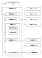
- FIG. 2 is a block diagram showing an electrical configuration of the component mounter of FIG. 1
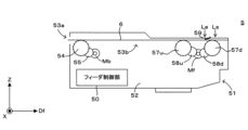
- FIG. 2 is a side view illustrating a schematic configuration of a tape feeder.
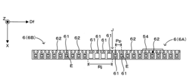
- FIG. 4 is a plan view illustrating a schematic configuration of a component supply tape.
- 5 is a flowchart showing an example of component supply control executed by the component mounter.
- FIG. 6 is a plan view showing an example of an operation executed according to the component supply control shown in FIG. 5 .
- FIG. 1 is a partial plan view showing a schematic diagram of a component mounter according to the present invention
- FIG. 2 is a block diagram showing the electrical configuration of the component mounter of FIG. 1.
- the X direction which is the horizontal direction
- the Y direction which is the horizontal direction perpendicular to the X direction
- the Z direction which is the vertical direction
- the component mounter 1 includes a main control unit 100 that controls the entire device, and the main control unit 100 includes an arithmetic processing unit 110, a drive control unit 120, a memory unit 130, an image capture control unit 140, and a feeder communication unit 150.
- the arithmetic processing unit 110 is a processor including a CPU (Central Processing Unit) and a RAM (Random Access Memory), and controls the drive control unit 120, the image capture control unit 140, and the feeder communication unit 150 based on the programs and data stored in the memory unit 130, thereby controlling the operations described below.
- the memory unit 130 is a storage device such as an SSD (Solid State Drive), and stores the number of components stored Q and the number of joints N, which will be described later.
- the component mounter 1 also includes a user interface 160, which is, for example, a touch panel display, and the arithmetic processing unit 110 executes control in response to input from the user interface 160 and displays information on the display of the user interface 160.
- the component mounter 1 has a pair of conveyors 12, 12 arranged on a base 11. Each conveyor 12 is composed of a belt conveyor arranged parallel to the X direction.
- the component mounter 1 transports the board B by controlling the conveyor 12 with a drive control unit 120.
- the component mounter 1 mounts components E (FIG. 4) on the board B that has been transported by the conveyor 12 from the upstream side in the X direction (board transport direction) to a work position (the position of board B in FIG. 1), and transports the board B, with component mounting completed, from the work position to the downstream side in the X direction by the conveyor 12.
- Two component supply units 25 are lined up in the X direction on each side of the pair of conveyors 12, 12 in the Y direction, and in each component supply unit 25, multiple tape feeders 5 are lined up in the X direction.
- a component supply reel is arranged for each tape feeder 5, on which a component supply tape 6 ( Figure 4) is wound, which contains small pieces of components E such as integrated circuits, transistors, capacitors, etc. at a predetermined pitch.
- Each tape feeder 5 supplies components E to a supply position Ls at the tip of the component supply tape 6 by intermittently feeding out the component supply tape 6 pulled out from the component supply reel.
- the calculation processing unit 110 controls the operation of the tape feeder 5 by issuing commands to the feeder control unit 50 of the tape feeder 5 via the feeder communication unit 150.
- a component recognition camera 7 is attached to the base 11 facing upward.
- This component recognition camera 7 captures an image of the component E from below before it is mounted on the board B, and transmits the acquired component recognition image Ir to the imaging control unit 140.
- the imaging control unit 140 recognizes the position of the component E based on the component recognition image Ir received from the component recognition camera 7.
- the component mounter 1 is provided with a pair of Y-axis rails 21, 21 extending in the Y direction, a Y-axis ball screw 22 extending in the Y direction, and a Y-axis motor My that rotates and drives the Y-axis ball screw 22, and an X-axis rail 23 is fixed to the nut of the Y-axis ball screw 22 while being supported by the pair of Y-axis rails 21, 21 so as to be movable in the Y direction.
- An X-axis ball screw 24 extending in the X direction and an X-axis motor Mx that rotates and drives the X-axis ball screw 24 are attached to the X-axis rail 23, and the head unit 3 is fixed to the nut of the X-axis ball screw 24 while being supported by the X-axis rail 23 so as to be movable in the X direction. Therefore, the drive control unit 120 can rotate the Y-axis ball screw 22 by the Y-axis motor My to move the head unit 3 in the Y direction, or rotate the X-axis ball screw 24 by the X-axis motor Mx to move the head unit 3 in the X direction.
- the head unit 3 has multiple (six) mounting heads 31 lined up in the X direction. Furthermore, the head unit 3 has a Z-axis motor Mz for each mounting head 31 that raises and lowers the mounting head 31. Each mounting head 31 has an elongated shape that extends in the Z direction (vertical direction), and has a detachable nozzle at its lower end for suctioning the component E. Then, component mounting is performed by the mounting head 31 as follows.
- the drive control unit 120 uses the X-axis motor Mx and the Y-axis motor My to make the nozzle of the mounting head 31 face the supply position Ls from above.
- the drive control unit 120 uses the Z-axis motor Mz to lower the mounting head 31 and bring the nozzle into contact with the component E supplied to the supply position Ls by the tape feeder 5.
- the drive control unit 120 raises the mounting head 31 (component adsorption).
- the drive control unit 120 uses the X-axis motor Mx and the Y-axis motor My to make the mounting head 31 face the component recognition camera 7. Then, the imaging control unit 140 causes the component recognition camera 7 to capture an image of the component E adsorbed by the mounting head 31 to obtain a component recognition image Ir, and recognizes the position of the component E based on the component recognition image Ir. Next, the drive control unit 120 moves the mounting head 31 above the board B using the X-axis motor Mx and the Y-axis motor My.
- the drive control unit 120 lowers the mounting head 31 using the Z-axis motor Mz, causing the component E picked up by the nozzle of the mounting head 31 to come into contact with the upper surface of the board B.
- the drive control unit 120 controls the position of the component E in the X and Y directions relative to the board B based on the position of the component E recognized by the component recognition image Ir. Then, the suction of the component E is released, and the component E is mounted on the board B.
- a board recognition camera 8 is attached to the head unit 3 facing downward, and moves in the X and Y directions along with the head unit 3.
- This board recognition camera 8 is used to capture an image of a fiducial mark attached to board B, and the imaging control unit 140 recognizes the position of board B based on the image of the fiducial mark captured by the board recognition camera 8. Then, the drive control unit 120 controls the position of the mounting head 31 based on the position of board B, thereby enabling components E to be mounted accurately on board B.
- the board recognition camera 8 is also used to capture an image of the supply position Ls of the component supply tape 6 attached to the tape feeder 5 to obtain a supply position image Is.
- FIG. 3 is a side view showing a schematic diagram of the tape feeder configuration.
- the feed direction Df parallel to the Y direction
- the side of the arrow in the feed direction Df is treated as the "front" of the feed direction Df
- the side opposite the arrow in the feed direction Df is treated as the "rear" of the feed direction Df.
- the tape feeder 5 has a mechanical feeder body 51, feeder motors Mf, Mb that drive the component supply tape 6, and a feeder control unit 50 that controls the feeder motors Mf, Mb in response to commands received from the feeder communication unit 150.
- the feeder body 51 has a flat case 52 that is thin in the X direction and long in the feed direction Df.
- the case 52 houses the above-mentioned feeder control unit 50 inside.
- a tape insertion port 53a extending in the Z direction opens, and a supply position Ls is provided on the upper surface of the front end portion of the case 52 in the feed direction Df.
- a tape transport path 53b is provided within the feeder body 51, leading from the tape insertion port 53a to the supply position Ls.
- This feeder body 51 feeds components to the supply position Ls by feeding the component supply tape 6 inserted into the tape transport path 53b from the tape insertion port 53a in the feed direction Df using the driving force of the feeder motors Mf and Mb.
- the feeder body 51 has a sprocket 54 arranged adjacent to the tape insertion opening 53a below the tape transport path 53b, and a gear 55 that transmits the driving force of the feeder motor Mb to the sprocket 54, housed within the case 52.
- the sprocket 54 rotates due to the driving force generated by the feeder motor Mb. Therefore, by rotating in the forward direction (forward rotation), the feeder motor Mb can transport the component supply tape 6 engaged with the sprocket 54 in the feed direction Df.
- the feeder body 51 has, inside the case 52, two sprockets 57d, 57u located at its front end portion and adjacent to the tape transport path 53b from below, and two gears 58d, 58u that transmit the driving force of the feeder motor Mf to the sprockets 57d, 57u, respectively.
- the sprockets 57d, 57u are rotated by the driving force generated by the feeder motor Mf. Therefore, by rotating in the forward direction (forward rotation), the feeder motor Mf can transport the component supply tape 6 engaged with the sprockets 57d, 57u in the feed direction Df.
- the component supply tape 6 inserted into the tape transport path 53b from the tape insertion port 53a engages with the sprockets 54, 57u, and 57d, thereby attaching the component supply tape 6 to the tape feeder 5.
- the feeder control unit 50 controls the rotation of the sprockets 54, 57u, and 57d by the feeder motors Mf and Mb to intermittently transport the component supply tape 6 in the feed direction Df. This allows multiple components E stored on the component supply tape 6 to be supplied in sequence to the supply position Ls.
- the tape feeder 5 also has a cutter 59 that opens the component supply tape 6 at an opening position Le near the upstream side of the supply position Ls in the feed direction Df.
- This cutter 59 comes into contact with the component supply tape 6 at the opening position Le, and cuts and opens the component supply tape 6 that passes through the opening position Le in the feed direction Df, thereby exposing the component E at the supply position Ls.
- the method of exposing the component E is not limited to this example, and may be performed by peeling off the cover tape of the component supply tape 6.
- FIG. 4 is a plan view showing a schematic configuration of the component supply tape. Note that FIG. 4 also shows the sprocket 54 of the tape feeder 5.
- the component supply tape 6 has a number of pockets 61 arranged at a predetermined arrangement pitch Pp in the feed direction Df, and the pockets 61 store the components E.
- the component supply tape 6 also has a number of engagement holes 62 arranged in the feed direction Df, and each sprocket 54, 57d, 57u of the tape feeder 5 rotates while engaging with the engagement holes 62, thereby transporting the component supply tape 6 in the feed direction Df.
- FIG. 4 also shows two component supply tapes 6 connected in series in the feed direction Df. That is, of the two component supply tapes 6, in the feed direction Df, the upstream end (i.e., the rear end) of the first downstream component supply tape 6A is connected to the downstream end (i.e., the front end) of the next component supply tape 6B upstream of the component supply tape 6A at a seam J.
- the splicing work for connecting these component supply tapes 6A and 6B is performed by an operator. When the operator completes the splicing work, the operator inputs to the user interface 160 indicating the completion of the splicing work, and the calculation processing unit 110 receives the input to the user interface 160 and confirms the completion of the splicing work.
- a seam detection region Rj is provided at the downstream end (i.e., the front end) of the component supply tape 6B in the feed direction Df.
- N pockets 61 i.e., empty pockets 61
- the N empty pockets 61 arranged continuously in the seam detection region Rj are arranged adjacent to the seam J.
- N is the number of empty pockets 61 to be arranged in the seam detection region Rj (seam number N), and is an integer equal to or greater than 2.
- the seam number N is 4.
- the seam number N is stored in the memory unit 130.
- the memory unit 130 also stores the component storage number Q, which is the number of components E stored in one component supply tape 6.
- FIG. 5 is a flow chart showing an example of component supply control executed by a component mounter
- FIG. 6 is a plan view showing a schematic example of an operation executed according to the component supply control of FIG. 5.
- the component supply control of FIG. 5 is executed by the main control unit 100. This component supply control is executed individually for each of the multiple tape feeders 5. However, since the content of the component supply control for each tape feeder 5 is the same, the component supply control executed for one tape feeder 5 will be described here.
- step S101 the drive control unit 120 causes the tape feeder 5 to perform pitch feeding, which feeds the component supply tape 6A in the feed direction Df by a distance equivalent to the array pitch Pp. This causes the component E to be supplied to the supply position Ls. Furthermore, in step S101, the drive control unit 120 causes the mounting head 31 to perform component suction, which picks up the component E from the supply position Ls. In this way, a supply and suction operation is performed, which supplies the component E to the supply position Ls and picks up the component E from the supply position Ls.
- step S102 the arithmetic processing unit 110 judges whether the mounting head 31 has failed to pick up the component.
- the success or failure of the component pick-up can be judged, for example, by a method based on the pressure generated in the mounting head 31, or a method based on the component recognition image Ir. In the former method, if the pressure (negative pressure) generated in the mounting head 31 is equal to or lower than a predetermined threshold pressure, the arithmetic processing unit 110 judges that the mounting head 31 has succeeded in picking up the component, whereas if the pressure generated in the mounting head 31 is greater than the predetermined threshold pressure, the arithmetic processing unit 110 judges that the mounting head 31 has failed to pick up the component.
- the arithmetic processing unit 110 judges that the mounting head 31 has succeeded in picking up the component, whereas if the component recognition image Ir does not show the component E to be picked up by the mounting head 31, the arithmetic processing unit 110 judges that the mounting head 31 has failed to pick up the component.
- the calculation processing unit 110 determines that the mounting head 31 has succeeded in picking up the component, i.e., that no pick-up error has occurred ("NO" in step S102), it initializes the consecutive error count, i.e., resets it to zero (step S103), and returns to step S101.
- the consecutive error count is the number of consecutive times that it has been determined in step S102 that a pick-up error has occurred, and is counted by the calculation processing unit 110.
- step S104 it increments the number of consecutive errors by one (step S104) and proceeds to step S105.
- step S105 it is determined whether the number of consecutive errors has exceeded the number of retries.
- the number of retries is the number of times that triggers the user interface 160 to issue an error notification indicating frequent pickup errors, and is, for example, "5".
- step S107 the calculation processing unit 110 determines whether or not completion of the splicing operation of connecting the component supply tape 6B to the component supply tape 6A has been confirmed. If completion of the splicing operation has not been confirmed ("NO" in step S107), the calculation processing unit 110 returns to step S101. On the other hand, if completion of the splicing operation has been confirmed ("YES" in step S107), the calculation processing unit 110 proceeds to step S108.
- step S108 the calculation processing unit 110 determines whether the number of consecutive errors is equal to or greater than the trigger count.
- the trigger count is an integer equal to or greater than 2 and smaller than the retry count.
- the "Operation M1" column in Figure 6 shows a state in which, of the components E stored on the component supply tape 6A, the component E at the most upstream (rear end) in the feed direction Df is supplied to supply position Ls by pitch feed in step S101.
- the "Operation M2" column in Figure 6 shows a state in which the component E supplied to supply position Ls by pitch feed is picked up by the mounting head 31 by component suction in step S101. This component suction is successful, and the component E is removed from the pocket 61 at supply position Ls.
- step S108 is judged as "NO” and the process returns to step S101.
- step S101 as shown in the "Operation M4" column in FIG. 6, pitch feed is performed to send the empty pocket 61b adjacent to the empty pocket 61a to the supply position Ls, and then the mounting head 31 performs (attempts) component suction on the pocket 61b at the supply position Ls. Because this component suction fails, it is judged in step S102 that a suction error has occurred (judged as "YES"), and the number of consecutive errors is incremented from "1" to "2" (step S104).
- step S108 is judged as "NO” and the process returns to step S101.
- step S101 as shown in the "Operation M5" column in FIG. 6, pitch feed is performed to send the empty pocket 61c adjacent to the empty pocket 61b to the supply position Ls, and then the mounting head 31 performs (attempts) component suction on the pocket 61c at the supply position Ls. Because this component suction fails, it is judged in step S102 that a suction error has occurred (judged as "YES"), and the number of consecutive errors is incremented from "2" to "3" (step S104).
- step S109 the drive control unit 120 faces the board recognition camera 8 from above to the supply position Ls, and the imaging control unit 140 causes the board recognition camera 8 to capture an image of the supply position Ls, thereby acquiring a supply position image Is (first image).
- step S110 the calculation processing unit 110 determines whether or not there is a component E at the supply position Ls, based on the supply position image Is acquired in step S109. If it is determined that there is a component E at the supply position Ls ("YES" in step S110), the calculation processing unit 110 resets the number of consecutive errors to "0" (step S111) and returns to step S101.
- step S110 if it is determined that there is no part E at the supply position Ls ("NO" at step S110), the calculation processing unit 110 proceeds to step S112. In the example of FIG. 6, there is no part E at the supply position Ls when the operation M5 is executed, so the result at step S110 is "NO".
- step S112 after the drive control unit 120 executes pitch feed, the imaging control unit 140 causes the board recognition camera 8 to capture an image of the pocket 61 sent to the supply position Ls by the pitch feed, and acquires a supply position image Is.
- step S113 the calculation processing unit 110 determines whether or not there is a component E at the supply position Ls, based on the supply position image Is acquired in step S112. If it is determined that there is a component E at the supply position Ls ("YES" in step S113), the calculation processing unit 110 resets the number of consecutive errors to "0" (step S111) and returns to step S101.
- step S114 after the drive control unit 120 executes pitch feed, the imaging control unit 140 causes the board recognition camera 8 to capture an image of the pocket 61 sent to the supply position Ls by the pitch feed, and acquires a supply position image Is (second image).
- step S115 the calculation processing unit 110 determines whether or not there is a component E at the supply position Ls, based on the supply position image Is acquired in step S114. If it is determined that there is no component E at the supply position Ls ("NO" in step S115), the calculation processing unit 110 re-executes step S114.
- N is the number of empty pockets 61 to be provided in the seam detection region Rj (the number of seams N). Therefore, if the number of empty pockets 61 provided at seam J in the splicing operation is correctly N, the presence of part E should be confirmed in the first step S115. However, if the worker erroneously provides more than N empty pockets 61 during the splicing operation, the presence of part E is not confirmed in the first step S115. Therefore, steps S114 and S115 are repeated until the presence of part E is confirmed.
- step S116 the calculation processing unit 110 executes tape switching processing associated with switching from component supply tape 6A to component supply tape 6B. Specifically, the calculation processing unit 110 initializes the remaining number of components managed by the calculation processing unit 110. That is, the calculation processing unit 110 manages the remaining number of components E as the number of stored components Q minus the number of times pitch feeding has been performed, whereas in step S116, the remaining number of components E is reset to the number of stored components Q, and the remaining number of components on component supply tape 6B is managed as the number of stored components Q.
- a supply and suction operation is performed in which the mounting head 31 attempts to suck up a component E from the supply position Ls (step S101). Then, if the mounting head 31 fails to suck up a component in two or more consecutively performed supply and suction operations triggered by the trigger ("YES" in step S108), the board recognition camera 8 (camera) is caused to capture an image of the supply position Ls to obtain a supply position image Is (first image) (step S109), and the state of the pocket 61 at the supply position Ls (i.e., the presence or absence of a component E in the pocket 61) is determined based on the supply position image Is (step S110). Therefore, if the mounting head 31 fails to suck up a component E repeatedly, it is possible to confirm the cause.
- the main control unit 100 also determines whether the pocket 61 located at the supply position Ls imaged by the board recognition camera 8 is the pocket 61 provided at the seam J between the two connected component supply tapes 6A, 6B based on the supply position image Is (first image) (steps S110, S112 to S116). With this configuration, the seam J between the two component supply tapes 6A, 6B can be accurately detected based on the state of the pocket 61 when the mounting head 31 fails to pick up a component E consecutively.
- a memory unit 130 is provided that stores the number N (N is an integer equal to or greater than 3) of pockets 61 to be provided at the seam J.
- the number of triggers is set to be greater than or equal to 2 and less than or equal to (N-1).
- the main control unit 100 determines that there is no component E in the pocket 61 of the supply position Ls based on the supply position image Is (first image) acquired in step S109 ("NO" in step S110), it causes the tape feeder 5 to perform pitch feed and then causes the board recognition camera 8 to capture an image of the supply position Ls to acquire a supply position image Is (second image) (step S114). Then, the main control unit 100 determines whether or not there is a component E in the pocket 61 of the supply position Ls based on the supply position image Is acquired in step S114 (step S115). In particular, the processes of steps S114 and S115 (feed determination process) are repeated until it is determined that there is a component E in the pocket 61 of the supply position Ls.
- the main control unit 100 determines that there is no component E in N or more consecutive pockets 61 based on the supply position image Is (first image) acquired in step S109 and the supply position image Is (second image) acquired in step S114, it determines that the N or more consecutive pockets 61 are pockets 61 provided at the seam J (step S116). In this configuration, based on confirming a pocket 61 containing component E following N or more consecutive pockets 61 containing no component E ("YES" in step S115), the seam J can be accurately detected.
- consecutive (N-trigger count) or more pockets 61 are imaged in sequence at the supply position Ls, and the supply position image Is is acquired by the board recognition camera 8 (steps S109, S112, S114).
- the main control unit 100 determines that no component E is present in each of the (N-trigger count) or more supply position images Is thus acquired (“NO” in steps S110, S113, S115), it determines that there are N or more consecutive pockets 61 without component E, and determines that the N or more pockets 61 are pockets 61 provided at the seam J. This allows the seam J to be accurately detected based on the confirmation of a pocket 61 with component E following N or more consecutive pockets 61 without component E ("YES" in step S115).
- the main control unit 100 determines that the number of consecutive pockets 61 without components E is less than N based on the supply position image Is (first image) acquired in step S109 and the supply position image Is (second image) acquired in step S114 ("YES" in steps S110 and S113), it determines that the pocket 61 shown in the supply position image Is (first image) acquired in step S109 is not a pocket 61 provided at the seam J (step S111). With this configuration, erroneous detection of the seam J can be accurately prevented.
- a user interface 160 (work status acquisition unit) is provided that accepts a work completion input indicating the completion of the splicing work of connecting the two component supply tapes 6A and 6B to each other. Then, when the number of consecutive supply and suction operations (step S101) in which the mounting head 31 fails to suction components reaches the trigger number ("YES" in step S108) while the user interface 160 has accepted the work completion input, the main control unit 100 acquires a supply position image Is (first image) (step S109).
- the supply position image Is is acquired, and the state of the pocket 61 at the supply position Ls can be determined based on the supply position image Is (steps S109, S110). Therefore, it is possible to detect the joint J at a reasonable timing.
- step S101 when the number of times that the mounting head 31 has failed to pick up a component during the supply suction operation (step S101) reaches the trigger count, if the user interface 160 has not accepted an input indicating that the operation is complete (if "NO" in step S107), the supply position image Is is not acquired.
- a user interface 160 (notification unit) is provided to notify the operator of an error. Then, when the number of times of supply and suction operations (step S101) in which the mounting head 31 fails to pick up components reaches a retry count (error notification count) that is greater than the trigger count ("YES" in step S105), the main control unit 100 causes the user interface 160 to notify the operator of an error (step S106).
- a retry count error notification count
- the main control unit 100 causes the user interface 160 to notify the operator of an error (step S106).
- the number of retries is greater than the trigger count.
- the mounting head 31 fails to pick up components repeatedly as the joint J reaches the supply position Ls, it is possible to prevent the cause from being erroneously determined to be a malfunction in the mounting head 31 or the like and an error from being notified to the operator.
- the component mounter 1 corresponds to an example of a "component mounter” of the present invention
- the main control unit 100 corresponds to an example of a “control unit” of the present invention
- the user interface 160 corresponds to an example of a "work status acquisition unit” and "notification unit” of the present invention
- the mounting head 31 corresponds to an example of a "mounting head” of the present invention
- the tape feeder 5 corresponds to an example of a "tape feeder” of the present invention
- the component supply tape 6 corresponds to an example of a "component supply tape” of the present invention
- the pocket 61 corresponds to an example of a “pocket” of the present invention
- the board recognition Camera 8 corresponds to an example of a "camera” in the present invention
- feed direction Df corresponds to an example of a "feed direction” in the present invention
- part E corresponds to an example of a "part” in the present invention
- supply position image Is acquired in step S109 corresponds to an example of a "
- the remaining number of components E on the component supply tape 6 can be managed as follows. That is, as described above, the calculation processing unit 110 manages the remaining number of components E by subtracting the number of times pitch feeding has been performed from the number of components stored Q. At this time, the number of components E actually stored on the component supply tape 6 can be found based on the seams J, and this can be used as the number of components stored Q.
- the calculation processing unit 110 determines the number of stored components Q, which is the number of components E stored on the component supply tape 6A, based on the number of pitch feeds repeatedly performed on the component supply tape 6A before determining the pocket 61 provided corresponding to the seam J.
- the calculation processing unit 110 then manages the remaining number of components E to be stored on the next component supply tape 6B based on the number of components E picked up from the component supply tape 6B and the number of stored components Q.
- the location of the seam detection area Rj is not limited to the above example. Therefore, the seam detection area Rj may be provided at the upstream end (i.e., the rear end) in the feed direction Df of the previous component supply tape 6A, rather than the next component supply tape 6B.
- the number of triggers can also be changed as appropriate. Therefore, the number of triggers may be the number of seams, N. In this case, steps S112 and S113 may be omitted. Alternatively, the number of triggers can be set as appropriate to (N-M) times (M is an integer equal to or greater than 1). In this case, steps S112 and S113 may be executed M times.
- component mounter 100 main control unit 160... user interface (work status acquisition unit, notification unit) 31: mounting head 5: tape feeder 6: component supply tape 61: pocket 8: board recognition camera (camera) Df...Feed direction E...Part Is...Supply position image (first image, second image) J: Joint Ls: Supply position Pp: Array pitch
Landscapes
- Engineering & Computer Science (AREA)
- Operations Research (AREA)
- Manufacturing & Machinery (AREA)
- Microelectronics & Electronic Packaging (AREA)
- Supply And Installment Of Electrical Components (AREA)
Abstract
テープフィーダ5がピッチ送りを実行してから、供給位置Lsから部品Eを吸着する部品吸着を実装ヘッド31が試行する供給吸着動作が実行される(ステップS101)。そして、連続して実行された2回以上のトリガ回数の供給吸着動作において実装ヘッド31が部品吸着に失敗すると(ステップS108で「YES」)、基板認識カメラ8(カメラ)に供給位置Lsを撮像させて供給位置画像Is(第1画像)が取得されて(ステップS109)、当該供給位置画像Isに基づき供給位置Lsのポケット61の状態(すなわち、ポケット61における部品Eの有無)が判定される(ステップS110)。
Description
この発明は、所定の配列ピッチで一列に配列された複数のポケットを有する部品供給テープをテープフィーダにより送ることでポケットに収容される部品を供給位置に供給する技術に関し、特に供給位置におけるポケットの状態を判定する技術に関する。
部品を基板に実装する部品実装機では、テープフィーダによって部品供給テープを送ることで、部品供給テープのポケットに収納された部品を供給位置に供給するテープフィーダが用いられる。つまり、供給位置に供給された部品は、供給位置から基板に実装ヘッドによって移載される。また、供給位置から部品が取り出されると、テープフィーダが部品供給テープを送って、供給位置に部品を供給する。このような動作が繰り返されることで、基板への部品の実装を継続することができる。また、特許文献1に記載されるように、テープフィーダが部品供給に使用中の先の部品供給テープにおける部品の残数が少なくなると、次の部品供給テープの先端を先の部品供給テープの後端に接続するスプライシング作業が実行される。
ところで、先の部品供給テープから次の部品供給テープへの切り換わりの確認のために、これらの部品供給テープのつなぎ目の供給位置への到達を検知するといった制御が適宜実行される。具体的には、スプライシング作業では、2個以上の所定個数の空ポケット(部品を収容しないポケット)がつなぎ目に隣接して設けられる。そして、実装ヘッドによる供給箇所からの部品の吸着が、空ポケットの個数に相当する回数だけ連続して失敗すると、つなぎ目が供給位置へ到達したと判定される。しかしながら、部品の吸着の失敗は、供給位置のポケットに部品がない場合の他に、供給位置のポケットに収納された部品を実装ヘッドが吸着できなかった場合にも生じうる。したがって、確実なつなぎ目の検知のために、部品の吸着に失敗した原因を確認できる技術が求められていた。
この発明は上記課題に鑑みなされたものであり、実装ヘッドが部品の吸着に連続して失敗した場合にその原因を確認可能とする技術の提供を目的とする。
本発明に係る部品実装機は、所定の配列ピッチで一列に配列された複数のポケットを有する部品供給テープをフィード方向に送るピッチ送りを実行することでポケットに収容される部品を供給位置に供給するテープフィーダと、供給位置から部品を吸着する部品吸着を実行する実装ヘッドと、テープフィーダにピッチ送りを実行させてから実装ヘッドに部品吸着を試行させる供給吸着動作を、テープフィーダおよび実装ヘッドに実行させる制御部と、供給位置を撮像するカメラとを備え、制御部は、連続して実行された2回以上のトリガ回数の供給吸着動作において実装ヘッドが部品吸着に失敗すると、カメラに供給位置を撮像させて第1画像を取得して、第1画像に基づき供給位置のポケットの状態を判定する。
本発明に係る部品供給テープのポケットの状態の判定方法は、所定の配列ピッチで一列に配列された複数のポケットを有する部品供給テープをフィード方向に送るピッチ送りを実行することでポケットに収容される部品を供給位置に供給するテープフィーダにピッチ送りを実行させてから、供給位置から部品を吸着する部品吸着を実装ヘッドに試行させる供給吸着動作を、テープフィーダおよび実装ヘッドに実行させる工程と、連続して実行された2回以上のトリガ回数の供給吸着動作において実装ヘッドが部品吸着に失敗すると、カメラに供給位置を撮像させて第1画像を取得する工程と、第1画像に基づき供給位置のポケットの状態を判定する工程とを備える。
このように構成された本発明(部品実装機および部品供給テープのポケットの状態の判定方法)では、テープフィーダがピッチ送りを実行してから、供給位置から部品を吸着する部品吸着を実装ヘッドが試行する供給吸着動作が実行される。そして、連続して実行された2回以上のトリガ回数の供給吸着動作において実装ヘッドが部品吸着に失敗すると、カメラに供給位置を撮像させて第1画像が取得されて、当該第1画像に基づき供給位置のポケットの状態が判定される。したがって、実装ヘッドが部品の吸着に連続して失敗した場合にその原因を確認することが可能となっている。
また、制御部は、カメラが撮像した供給位置に位置するポケットが、互いに接続された2本の部品供給テープのつなぎ目に対して設けられたポケットであるかを、第1画像に基づき判定するように、部品実装機を構成してもよい。かかる構成では、実装ヘッドが部品の吸着に連続して失敗した際のポケットの状態に基づき、2本の部品供給テープのつなぎ目を的確に検知できる。
また、つなぎ目に対して設けられるべきポケットの個数N(Nは3以上の整数)を記憶する記憶部をさらに備え、トリガ回数は、2以上であって(N-1)以下であるように、部品実装機を構成してもよい。かかる構成では、部品吸着に失敗した際に、供給吸着動作に伴って実装ヘッドが部品吸着を試行する回数を抑えることができ、2本の部品供給テープのつなぎ目の検出を迅速に行うことが可能となる。
また、制御部は、第1画像に基づき供給位置のポケットに部品がないと判定すると、テープフィーダにピッチ送りを実行させてから供給位置をカメラに撮像させて第2画像を取得して当該第2画像に基づき供給位置のポケットにおける部品の有無を判定する送り判定処理を、供給位置のポケットに部品があると判定されるまで繰り返すように、部品実装機を構成してもよい。かかる構成では、送り判定処理では、実装ヘッドに部品吸着を試行させることなく、カメラが撮像する第2画像に基づき、供給位置のポケットにおける部品の有無を迅速に判定することが可能となる。
また、制御部は、第1画像および第2画像に基づき、連続するN個以上のポケットに部品がないと判定すると、当該連続するN個以上のポケットがつなぎ目に対して設けられたポケットであると判定するように、部品実装機を構成してもよい。かかる構成では、部品がないポケットがN個以上連続したのに続いて部品があるポケットを確認したことに基づき、つなぎ目を的確に検知することができる。
また、制御部は、第1画像および第2画像に基づき、部品がないポケットが連続する個数がN個未満であると判定すると、第1画像が示すポケットはつなぎ目に対して設けられたポケットではないと判定するように、部品実装機を構成してもよい。かかる構成では、つなぎ目の誤検知を的確に抑止することができる。
また、制御部は、2本の部品供給テープのうち、フィード方向に下流側の先の部品供給テープに対して繰り返し実行したピッチ送りの回数と、つなぎ目に対して設けられたと判定したポケットとに基づき、先の部品供給テープに収納されていた部品の個数である部品収納個数を判定し、2本の部品供給テープのうち、先の部品供給テープよりフィード方向の上流側の次の部品供給テープに収納される部品の残数を、次の部品供給テープから吸着された部品の個数と部品収納個数とに基づき管理するように、部品実装機を構成してもよい。かかる構成では、部品供給テープに収納される部品収納個数が規定個数と異なる場合であっても、実際の部品収納個数に基づき、部品供給テープの部品の残数を的確に管理することができる。
また、2本の部品供給テープを互いに接続するスプライシング作業の完了を示す作業完了入力を受け付ける作業状態取得部をさらに備え、制御部は、作業状態取得部が作業完了入力を受け付けた状態で、実装ヘッドが部品吸着に失敗した供給吸着動作の回数がトリガ回数に達すると、第1画像を取得するように、部品実装機を構成してもよい。かかる構成では、スプライシングの作業に伴って、2本の部品供給テープのつなぎ目が供給位置に近づいている可能性が高い場面において、第1画像を取得して当該第1画像に基づき供給位置のポケットの状態を判定することができる。したがって、つなぎ目の検知を合理的なタイミングで実行することが可能となる。
また、実装ヘッドが部品吸着に失敗した供給吸着動作の回数がトリガ回数に達した際に、作業状態取得部が作業完了入力を受け付けていない場合には、第1画像を取得しないように、部品実装機を構成してもよい。かかる構成では、2本の部品供給テープのつなぎ目が供給位置に近づいている可能性がない場面において、つなぎ目の検知のために第1画像を無駄に取得することが抑えられる。
また、作業者にエラーを報知する報知部をさらに備え、制御部は、実装ヘッドが部品吸着に失敗した供給吸着動作の回数が、トリガ回数より多いエラー報知回数に到達すると、報知部にエラーを報知させるように、部品実装機を構成してもよい。かかる構成では、実装ヘッド等に不具合が発生して実装ヘッドの部品吸着の失敗が多発したような場合には、作業者にエラーを報知して、メンテナンスを促すことができる。また、エラー報知回数はトリガ回数より多い。そのため、つなぎ目が供給位置に到達したのに応じて実装ヘッドの部品吸着の失敗が連続した場合に、この原因を実装ヘッド等における不具合の発生と誤って判定して、作業者にエラーが報知されるのを抑えられる。
本発明によれば、実装ヘッドが部品の吸着に連続して失敗した場合にその原因を確認することが可能となる。
図1は本発明に係る部品実装機を模式的に示す部分平面図であり、図2は図1の部品実装機が備える電気的構成を示すブロック図である。図1および以下の図では、水平方向であるX方向、X方向に直交する水平方向であるY方向および鉛直方向であるZ方向を適宜示す。
図2に示すように、部品実装機1は、装置全体を統括的に制御する主制御部100を備え、主制御部100は、演算処理部110、駆動制御部120、記憶部130、撮像制御部140およびフィーダ通信部150を有する。演算処理部110は、CPU(Central Processing Unit)およびRAM(Random Access Memory)等で構成されたプロセッサであり、記憶部130に記憶されたプログラムやデータに基づき、駆動制御部120、撮像制御部140およびフィーダ通信部150を制御することで、後述する各動作を制御する。記憶部130は、SSD(Solid State Drive)等の記憶装置であり、後述する部品収納個数Qやつなぎ目個数N等を記憶する。また、部品実装機1には、例えばタッチパネルディスプレイで構成されたユーザーインターフェース160が設けられ、演算処理部110は、ユーザーインターフェース160の入力に応じて制御を実行したり、ユーザーインターフェース160のディスプレイに情報を表示したりする。
図1に示すように、部品実装機1は、基台11の上に設けられた一対のコンベア12、12を備える。各コンベア12は、X方向に平行に配置されたベルトコンベアで構成される。そして、部品実装機1は、駆動制御部120によってコンベア12を制御することで、基板Bの搬送を実行する。つまり、部品実装機1は、コンベア12によりX方向(基板搬送方向)の上流側から作業位置(図1の基板Bの位置)に搬入した基板Bに対して部品E(図4)を実装し、部品実装を完了した基板Bをコンベア12により作業位置からX方向の下流側へ搬出する。
一対のコンベア12、12のY方向の両側それぞれでは2つの部品供給部25がX方向に並んでおり、各部品供給部25では、複数のテープフィーダ5がX方向に並ぶ。各テープフィーダ5に対しては、集積回路、トランジスタ、コンデンサ等の小片状の部品Eを所定ピッチで収納した部品供給テープ6(図4)が巻き付けられた部品供給リールが配置されており、各テープフィーダ5は部品供給リールから引き出された部品供給テープ6を間欠的に送り出すことで、その先端部の供給位置Lsに部品Eを供給する。なお、演算処理部110は、フィーダ通信部150を介してテープフィーダ5のフィーダ制御部50に指令を出すことで、テープフィーダ5の動作を制御する。
X方向に並ぶ2個の部品供給部25の間には、部品認識カメラ7が上方を向いて基台11に取り付けられている。この部品認識カメラ7は、基板Bに実装される前の部品Eを下方から撮像することで取得した部品認識画像Irを、撮像制御部140に送信する。撮像制御部140は、部品認識カメラ7から受信した部品認識画像Irに基づき、部品Eの位置を認識する。
また、部品実装機1では、Y方向に延びる一対のY軸レール21、21と、Y方向に延びるY軸ボールネジ22と、Y軸ボールネジ22を回転駆動するY軸モーターMyとが設けられ、X軸レール23が一対のY軸レール21、21にY方向に移動可能に支持された状態でY軸ボールネジ22のナットに固定されている。X軸レール23には、X方向に延びるX軸ボールネジ24と、X軸ボールネジ24を回転駆動するX軸モーターMxとが取り付けられており、ヘッドユニット3がX軸レール23にX方向に移動可能に支持された状態でX軸ボールネジ24のナットに固定されている。したがって、駆動制御部120は、Y軸モーターMyによりY軸ボールネジ22を回転させてヘッドユニット3をY方向に移動させ、あるいはX軸モーターMxによりX軸ボールネジ24を回転させてヘッドユニット3をX方向に移動させることができる。
ヘッドユニット3は、X方向に並ぶ複数(6本)の実装ヘッド31を有する。さらに、ヘッドユニット3には、実装ヘッド31を昇降させるZ軸モーターMzを各実装ヘッド31に対して有する。各実装ヘッド31はZ方向(鉛直方向)に延びた長尺形状を有し、部品Eを吸着するためのノズルをその下端に着脱可能に有する。そして、実装ヘッド31によって部品実装が次のように実行される。
つまり、駆動制御部120は、X軸モーターMxおよびY軸モーターMyによって、実装ヘッド31のノズルを供給位置Lsに上方から対向させる。次に、駆動制御部120は、Z軸モーターMzによって実装ヘッド31を下降させて、テープフィーダ5によって供給位置Lsに供給された部品Eにノズルを接触させる。そして、実装ヘッド31がノズルに供給する負圧によって部品Eをノズルに吸着すると、駆動制御部120は実装ヘッド31を上昇させる(部品吸着)。こうして実装ヘッド31が部品吸着を実行して、供給位置Lsからの部品Eのピックアップを完了すると、駆動制御部120は、X軸モーターMxおよびY軸モーターMyによって実装ヘッド31を部品認識カメラ7に対向させる。そして、撮像制御部140は、実装ヘッド31に吸着される部品Eを部品認識カメラ7に撮像させて部品認識画像Irを取得し、当該部品認識画像Irに基づき当該部品Eの位置を認識する。続いて、駆動制御部120は、X軸モーターMxおよびY軸モーターMyによって実装ヘッド31を基板Bの上方に移動させる。そして、駆動制御部120は、Z軸モーターMzによって実装ヘッド31を下降させて実装ヘッド31のノズルに吸着される部品Eを基板Bの上面に接触させる。この際、駆動制御部120は、基板Bに対する部品EのX方向およびY方向への位置を、部品認識画像Irにより認識した部品Eの位置に基づき制御する。そして、部品Eの吸着が解除されて、部品Eが基板Bに実装される。
また、ヘッドユニット3には、基板認識カメラ8が下方を向いて取り付けられており、基板認識カメラ8は、ヘッドユニット3に伴ってX方向およびY方向へ移動する。この基板認識カメラ8は、基板Bに付されたフィデューシャルマークの撮像に用いられ、撮像制御部140は、基板認識カメラ8によって撮像されたフィデューシャルマークの画像に基づき、基板Bの位置を認識する。そして、駆動制御部120が基板Bの位置に基づき実装ヘッド31の位置を制御することで、基板Bに的確に部品Eを実装することができる。また、後述するように、基板認識カメラ8は、テープフィーダ5に装着された部品供給テープ6の供給位置Lsを撮像して供給位置画像Isを取得するのにも用いられる。
図3はテープフィーダの構成を模式的に示す側面図である。同図では、テープフィーダ5が部品供給テープ6を送り出すフィード方向Df(Y方向に平行)を示すとともに、フィード方向Dfの矢印側をフィード方向Dfの「前」と、フィード方向Dfの矢印の反対側をフィード方向Dfの「後ろ」と取り扱う。
テープフィーダ5は、機械的構成であるフィーダ本体51と、部品供給テープ6を駆動するフィーダモーターMf、Mbと、フィーダ通信部150から受信した指令に応じてフィーダモーターMf、Mbを制御するフィーダ制御部50とを有する。フィーダ本体51は、X方向に薄くてフィード方向Dfに長尺な偏平形状のケース52を有する。ケース52は上述のフィーダ制御部50を内部に収容している。また、ケース52のフィード方向Dfの後端では、Z方向に延設されたテープ挿入口53aが開口し、ケース52のフィード方向Dfの前端部分の上面に供給位置Lsが設けられている。そして、フィーダ本体51内ではテープ挿入口53aから供給位置Lsへ到るテープ搬送路53bが設けられている。このフィーダ本体51は、テープ挿入口53aからテープ搬送路53bに挿入された部品供給テープ6を、フィーダモーターMf、Mbの駆動力によってフィード方向Dfに送り出すことで、供給位置Lsに部品を供給する。
フィーダ本体51は、テープ搬送路53bの下方でテープ挿入口53aに隣接して配置されたスプロケット54と、フィーダモーターMbの駆動力をスプロケット54に伝達するギヤ55とをケース52内に有し、スプロケット54はフィーダモーターMbが発生する駆動力によって回転する。したがって、フィーダモーターMbは、順方向に回転(順回転)することで、スプロケット54に係合する部品供給テープ6をフィード方向Dfへ搬送することができる。
また、フィーダ本体51は、その前端部分に配置されて下方からテープ搬送路53bに隣接する2個のスプロケット57d、57uと、フィーダモーターMfの駆動力をスプロケット57d、57uにそれぞれ伝達する2個のギヤ58d、58uとをケース52内に有する。そして、スプロケット57d、57uはフィーダモーターMfが発生する駆動力によって回転する。したがって、フィーダモーターMfは、順方向に回転(順回転)することで、スプロケット57d、57uに係合する部品供給テープ6をフィード方向Dfへ搬送できる。
かかる構成では、テープ挿入口53aからテープ搬送路53bに挿入された部品供給テープ6がスプロケット54、57u、57dに係合することで、部品供給テープ6がテープフィーダ5に装着される。そして、フィーダ制御部50は、フィーダモーターMf、Mbによるスプロケット54、57u、57dの回転を制御することで、部品供給テープ6をフィード方向Dfに間欠的に搬送する。これによって、部品供給テープ6に収納された複数の部品Eを順番に供給位置Lsに供給することができる。
また、テープフィーダ5は、供給位置Lsのフィード方向Dfの上流側近傍の開放位置Leで部品供給テープ6を開放するカッタ59を有する。このカッタ59は、開放位置Leで部品供給テープ6に接触し、開放位置Leをフィード方向Dfに通過する部品供給テープ6を切断して開くことで、供給位置Lsにおいて部品Eを露出させる。なお、部品Eの露出方法は、この例に限られず、部品供給テープ6のカバーテープを剥離することによって行ってもよい。
図4は部品供給テープの構成を模式的に示す平面図である。なお、図4では、テープフィーダ5のスプロケット54が併せて示されている。部品供給テープ6は、フィード方向Dfに所定の配列ピッチPpで配列された複数のポケット61を有し、当該ポケット61に部品Eが収納される。また、部品供給テープ6は、フィード方向Dfに配列された複数の係合孔62を有し、テープフィーダ5の各スプロケット54、57d、57uは、この係合孔62に係合しつつ回転することで、部品供給テープ6をフィード方向Dfへ搬送する。
また、図4では、フィード方向Dfに直列に接続された2本の部品供給テープ6が示されている。つまり、2本の部品供給テープ6のうち、フィード方向Dfにおいて、下流側の先の部品供給テープ6Aの上流端(すなわち、後端)と、当該部品供給テープ6Aの上流側の次の部品供給テープ6Bの下流端(すなわち、前端)とが、つなぎ目Jで接続されている。これら部品供給テープ6A、6Bを接続するスプライシング作業は、作業者によって実行される。作業者は、スプライシング作業を完了すると、スプライシング作業の完了を示す入力をユーザーインターフェース160に対し実行し、演算処理部110は、ユーザーインターフェース160に対する入力を受けて、スプライシング作業の完了を確認する。
フィード方向Dfにおいて部品供給テープ6Bの下流端部(すなわち、前端部)には、つなぎ目検知領域Rjが設けられている。このつなぎ目検知領域Rjは、部品Eを収納しないN個のポケット61(すなわち、空ポケット61)がフィード方向Dfに連続して配列されている。つまり、つなぎ目検知領域Rjに連続して設けられたN個の空ポケット61が、つなぎ目Jに隣接して配列される。ここで、Nは、つなぎ目検知領域Rjに設けられるべき空ポケット61の個数(つなぎ目個数N)であり、2以上の整数である。ここの例では、つなぎ目個数Nは4である。上述の通り、つなぎ目個数Nは、記憶部130に記憶されている。また、記憶部130には、1本の部品供給テープ6に収納される部品Eの個数である部品収納個数Qが記憶されている。
図5は部品実装機で実行される部品供給制御の一例を示すフローチャートであり、図6は図5の部品供給制御に従って実行される動作の一例を模式的に示す平面図である。図5の部品供給制御は、主制御部100によって実行される。この部品供給制御は、複数のテープフィーダ5のそれぞれに対して個別に実行される。ただし、各テープフィーダ5に対する部品供給制御の内容は同一であるため、ここでは、一のテープフィーダ5に対して実行される部品供給制御について説明する。
ステップS101では、駆動制御部120は、部品供給テープ6Aをフィード方向Dfに配列ピッチPpに相当する距離だけ送るピッチ送りをテープフィーダ5に実行させる。これによって、部品Eが供給位置Lsに供給される。さらに、ステップS101では、駆動制御部120は、供給位置Lsから部品Eを吸着する部品吸着を実装ヘッド31に実行させる。こうして、供給位置Lsに部品Eを供給して供給位置Lsから部品Eを吸着する供給吸着動作が実行される。
ステップS102では、演算処理部110は、実装ヘッド31が部品吸着に失敗したか否かを判定する。部品吸着の成否は、例えば実装ヘッド31に発生する圧力による方法と、部品認識画像Irによる方法とによって判定できる。前者の方法では、演算処理部110は、実装ヘッド31に発生する圧力(負圧)が所定の閾圧力以下であれば、実装ヘッド31が部品吸着に成功したと判定する一方、実装ヘッド31に発生する圧力が所定の閾圧力より大きければ、実装ヘッド31が部品吸着に失敗したと判定する。後者の方法では、演算処理部110は、部品認識画像Irが実装ヘッド31に吸着される部品Eを示すのであれば、実装ヘッド31が部品の吸着に成功したと判定する一方、部品認識画像Irが実装ヘッド31に吸着される部品Eを示さないのであれば、実装ヘッド31が部品の吸着に失敗したと判定する。
演算処理部110は、実装ヘッド31が部品吸着に成功した、すなわち吸着エラーが発生しなかったと判定すると(ステップS102で「NO」)、連続エラー数を初期化、すなわちゼロにリセットして(ステップS103)、ステップS101に戻る。ここで、連続エラー数は、ステップS102で吸着エラーが発生したと連続して判定された回数であり、演算処理部110によってカウントされる。
演算処理部110は、実装ヘッド31が部品吸着に失敗した、すなわち吸着エラーが発生したと判定すると(ステップS102で「YES」)、連続エラー数を1だけインクリメントして(ステップS104)、ステップS105に進む。ステップS105では、連続エラー数がリトライ回数を超えたか否かを判定する。ここで、リトライ回数は、吸着エラーの頻発を示すエラー報知をユーザーインターフェース160に実行させるきっかけを与える回数であり、例えば「5」である。演算処理部110は、連続エラー数がリトライ回数を超えたと判定すると(ステップS105で「YES」)、エラー報知をユーザーインターフェース160に実行させる(ステップS106)。続いて、演算処理部110は、連続エラー数をゼロにリセットしてから(ステップS103)、ステップS101に戻る。
演算処理部110は、連続エラー数がリトライ回数以下であると判定すると(ステップS105で「NO」)、ステップS107に進む。ステップS107では、演算処理部110は、部品供給テープ6Aに部品供給テープ6Bを接続するスプライシング作業の完了を確認済みであるか否かを判定する。スプライシング作業の完了を未確認である場合(ステップS107で「NO」の場合)には、演算処理部110は、ステップS101に戻る。一方、スプライシング作業の完了を確認済みである場合(ステップS107で「YES」の場合)には、演算処理部110は、ステップS108に進む。
ステップS108では、演算処理部110は、連続エラー数がトリガ回数以上であるか否かを判定する。ここで、トリガ回数は、リトライ回数より小さい2以上の整数である。ここの例では、トリガ回数は、つなぎ目個数N(=4)から1を減算した値、すなわち3に設定されている。
図6の例を用いて、上記のフローを具体的に説明すると、図6の「動作M1」の欄では、部品供給テープ6Aに収納される部品Eのうち、フィード方向Dfの最上流(後端)の部品EがステップS101のピッチ送りによって供給位置Lsに供給された状態が示されている。また、図6の「動作M2」の欄では、ピッチ送りによって供給位置Lsに供給された部品EがステップS101の部品吸着によって実装ヘッド31によって吸着された状態が示されている。この部品吸着は成功して、供給位置Lsのポケット61から部品Eが取り出されている。
この動作M1およびM2に続くステップS102では、吸着エラーが発生しなかったと判定され(「NO」と判定)、ステップS103で連続エラー数が「0」にリセットされて、ステップS101に戻る。このステップS101では、図6の「動作M3」の欄に示すように、ピッチ送りが実行される。これによって、つなぎ目Jが供給位置Lsのフィード方向Dfの下流側に移動して、部品供給テープ6Bの空のポケット61aが供給位置Lsに送られる。さらに、ステップS101では、供給位置Lsのポケット61aに対して実装ヘッド31が部品吸着を実行(試行)する。この部品吸着は失敗するため、ステップS102で吸着エラーが発生したと判定されて(「YES」と判定)、連続エラー数が「0」から「1」にインクリメントされる(ステップS104)。
そして、ステップS105およびS107を経て、ステップS108に進む。連続エラー数(=1)はトリガ回数(=3)未満であるため、ステップS108では「NO」と判定されて、ステップS101に戻る。このステップS101では、図6の「動作M4」の欄に示すように、ピッチ送りが実行されて、空のポケット61aに隣接する空のポケット61bが供給位置Lsに送られてから、供給位置Lsのポケット61bに対して実装ヘッド31が部品吸着を実行(試行)する。この部品吸着は失敗するため、ステップS102で吸着エラーが発生したと判定されて(「YES」と判定)、連続エラー数が「1」から「2」にインクリメントされる(ステップS104)。
そして、ステップS105およびS107を経て、ステップS108に進む。連続エラー数(=2)はトリガ回数(=3)未満であるため、ステップS108では「NO」と判定されて、ステップS101に戻る。このステップS101では、図6の「動作M5」の欄に示すように、ピッチ送りが実行されて、空のポケット61bに隣接する空のポケット61cが供給位置Lsに送られてから、供給位置Lsのポケット61cに対して実装ヘッド31が部品吸着を実行(試行)する。この部品吸着は失敗するため、ステップS102で吸着エラーが発生したと判定されて(「YES」と判定)、連続エラー数が「2」から「3」にインクリメントされる(ステップS104)。
そして、ステップS105およびS107を経て、ステップS108に進む。ここでは、連続エラー数(=3)がトリガ回数(=3)以上であるため、ステップS108では「YES」と判定されて、ステップS109に進む。
ステップS109では、駆動制御部120が基板認識カメラ8を供給位置Lsに上側から対向させて、撮像制御部140が基板認識カメラ8に供給位置Lsを撮像させることで、供給位置画像Is(第1画像)を取得する。ステップS110では、演算処理部110は、ステップS109で取得した供給位置画像Isに基づき、供給位置Lsに部品Eがあるか否かを判定する。供給位置Lsに部品Eがあると判定すると(ステップS110で「YES」)、演算処理部110は、連続エラー数を「0」にリセットして(ステップS111)、ステップS101に戻る。
一方、供給位置Lsに部品Eがないと判定すると(ステップS110で「NO」)、演算処理部110は、ステップS112に進む。図6の例では、動作M5を実行時の供給位置Lsには部品Eが無いため、ステップS110では「NO」と判定される。
ステップS112では、駆動制御部120がピッチ送りを実行してから、撮像制御部140は当該ピッチ送りで供給位置Lsに送られたポケット61を基板認識カメラ8に撮像させて、供給位置画像Isを取得する。ステップS113では、演算処理部110は、ステップS112で取得した供給位置画像Isに基づき、供給位置Lsに部品Eがあるか否かを判定する。供給位置Lsに部品Eがあると判定すると(ステップS113で「YES」)、演算処理部110は、連続エラー数を「0」にリセットして(ステップS111)、ステップS101に戻る。
一方、供給位置Lsに部品Eがないと判定すると(ステップS113で「NO」)、演算処理部110は、ステップS114に進む。図6の「動作M6」の欄に示す例によれば、ステップS112では、ピッチ送りの実行によって、空のポケット61cに隣接する空のポケット61dが供給位置Lsに送られて、空のポケット61dを撮像した供給位置画像Isが取得される。したがって、ステップS113では、演算処理部110は、供給位置Lsに部品Eがないと判定して(ステップS113で「NO」と判定)、ステップS114に進む。
ステップS114では、駆動制御部120がピッチ送りを実行してから、撮像制御部140は当該ピッチ送りで供給位置Lsに送られたポケット61を基板認識カメラ8に撮像させて、供給位置画像Is(第2画像)を取得する。ステップS115では、演算処理部110は、ステップS114で取得した供給位置画像Isに基づき、供給位置Lsに部品Eがあるか否かを判定する。供給位置Lsに部品Eがないと判定すると(ステップS115で「NO」)、演算処理部110は、ステップS114を再実行する。
つまり、ステップS115の実行時点では、トリガ回数連続する吸着エラーのうちの初回の吸着エラーが発生してから、N回よりも多い回数、具体的には(N+1)回のピッチ送りが実行されている。上述の通り、Nは、つなぎ目検知領域Rjに設けられるべき空ポケット61の個数(つなぎ目個数N)である。したがって、スプライシング作業においてつなぎ目Jに対して設けられた空ポケット61の個数が正しくN個である場合には、最初のステップS115において部品Eの存在が確認されるはずである。ただし、作業者がスプライシング作業の際に、N個よりも多い空ポケット61を誤って設けた場合には、最初のステップS115においては部品Eの存在が確認されない。そこで、部品Eの存在が確認されるまで、ステップS114およびS115が繰り返される。
一方、供給位置Lsに部品Eがあると判定すると(ステップS115で「YES」)、演算処理部110は、ステップS116に進む。図6の「動作M7」の欄に示す例によれば、ステップS114では、ピッチ送りの実行によって、空のポケット61dに隣接するポケット61が供給位置Lsに送られ、このポケット61には部品Eがある。したがって、ステップS115では、演算処理部110は、供給位置Lsに部品Eがあると判定して(ステップS115で「NO」と判定)、ステップS116に進む。
ステップS116では、演算処理部110は、部品供給テープ6Aから部品供給テープ6Bへの切り換えに伴うテープ切換処理を実行する。具体的には、演算処理部110は、当該演算処理部110において管理する部品残数を初期化する。つまり、演算処理部110は、部品収納個数Qからピッチ送りの実行回数を減算した値を部品Eの残数として管理するのに対して、ステップS116では、部品Eの残数を部品収納個数Qにリセットして、部品供給テープ6Bの部品残数が部品収納個数Qであると管理する。
以上に説明する実施形態では、テープフィーダ5がピッチ送りを実行してから、供給位置Lsから部品Eを吸着する部品吸着を実装ヘッド31が試行する供給吸着動作が実行される(ステップS101)。そして、連続して実行された2回以上のトリガ回数の供給吸着動作において実装ヘッド31が部品吸着に失敗すると(ステップS108で「YES」)、基板認識カメラ8(カメラ)に供給位置Lsを撮像させて供給位置画像Is(第1画像)が取得されて(ステップS109)、当該供給位置画像Isに基づき供給位置Lsのポケット61の状態(すなわち、ポケット61における部品Eの有無)が判定される(ステップS110)。したがって、実装ヘッド31が部品Eの吸着に連続して失敗した場合にその原因を確認することが可能となっている。
また、主制御部100(制御部)は、基板認識カメラ8が撮像した供給位置Lsに位置するポケット61が、互いに接続された2本の部品供給テープ6A、6Bのつなぎ目Jに対して設けられたポケット61であるかを、供給位置画像Is(第1画像)に基づき判定する(ステップS110、S112~S116)。かかる構成では、実装ヘッド31が部品Eの吸着に連続して失敗した際のポケット61の状態に基づき、2本の部品供給テープ6A、6Bのつなぎ目Jを的確に検知できる。
また、つなぎ目Jに対して設けられるべきポケット61の個数N(Nは3以上の整数)を記憶する記憶部130が具備されている。これに対して、トリガ回数は2以上であって(N-1)以下に設定されている。かかる構成では、部品吸着に失敗した際に、供給吸着動作(ステップS101)に伴って実装ヘッド31が部品吸着を試行する回数を抑えることができ、2本の部品供給テープ6A、6Bのつなぎ目Jの検出を迅速に行うことが可能となる。
また、主制御部100は、ステップS109で取得した供給位置画像Is(第1画像)に基づき供給位置Lsのポケット61に部品Eがないと判定すると(ステップS110で「NO」)、テープフィーダ5にピッチ送りを実行させてから供給位置Lsを基板認識カメラ8に撮像させて供給位置画像Is(第2画像)を取得する(ステップS114)。そして、主制御部100は、ステップS114で取得した供給位置画像Isに基づき供給位置Lsのポケット61における部品Eの有無を判定する(ステップS115)。特に、ステップS114およびS115の処理(送り判定処理)を、供給位置Lsのポケット61に部品Eがあると判定されるまで繰り返す。かかる構成では、ステップS114およびS115の送り判定処理では、実装ヘッド31に部品吸着を試行させることなく、基板認識カメラ8がステップS114で撮像する供給位置画像Is(第2画像)に基づき、供給位置Lsのポケット61における部品Eの有無を迅速に判定することが可能となる。
また、主制御部100は、ステップS109で取得した供給位置画像Is(第1画像)およびステップS114で取得した供給位置画像Is(第2画像)に基づき、連続するN個以上のポケット61に部品Eがないと判定すると、当該連続するN個以上のポケット61がつなぎ目Jに対して設けられたポケット61であると判定する(ステップS116)。かかる構成では、部品Eがないポケット61がN個以上連続したのに続いて部品Eがあるポケット61を確認したことに基づき(ステップS115で「YES」)、つなぎ目Jを的確に検知することができる。
具体的には、トリガ回数だけ連続して吸着エラーが確認されて、連続エラー数がトリガ回数に到達すると(ステップS108で「YES」)、連続する(N-トリガ回数)個以上のポケット61が順番に供給位置Lsで撮像されて、供給位置画像Isが基板認識カメラ8によって取得される(ステップS109、S112、S114)。主制御部100は、こうして取得された(N-トリガ回数)個以上の供給位置画像Isのそれぞれについて部品Eが存在しないと判定すると(ステップS110、S113、S115で「NO」)、部品Eがないポケット61がN個以上連続したと判定して、当該N個以上のポケット61がつなぎ目Jに対して設けられたポケット61であると判定する。これによって、部品Eがないポケット61がN個以上連続したのに続いて部品Eがあるポケット61を確認したことに基づき(ステップS115で「YES」)、つなぎ目Jを的確に検知することができる。
また、主制御部100は、ステップS109で取得した供給位置画像Is(第1画像)およびステップS114で取得した供給位置画像Is(第2画像)に基づき、部品Eがないポケット61が連続する個数がN個未満であると判定すると(ステップS110、S113で「YES」)、ステップS109で取得した供給位置画像Is(第1画像)が示すポケット61はつなぎ目Jに対して設けられたポケット61ではないと判定する(ステップS111)。かかる構成では、つなぎ目Jの誤検知を的確に抑止することができる。
また、2本の部品供給テープ6A、6Bを互いに接続するスプライシング作業の完了を示す作業完了入力を受け付けるユーザーインターフェース160(作業状態取得部)が具備されている。そして、主制御部100は、ユーザーインターフェース160が作業完了入力を受け付けた状態で、実装ヘッド31が部品吸着に失敗した供給吸着動作(ステップS101)の連続回数がトリガ回数に達すると(ステップS108で「YES」)、供給位置画像Is(第1画像)を取得する(ステップS109)。かかる構成では、スプライシングの作業に伴って、2本の部品供給テープ6A、6Bのつなぎ目Jが供給位置Lsに近づいている可能性が高い場面において、供給位置画像Isを取得して当該供給位置画像Isに基づき供給位置Lsのポケット61の状態を判定することができる(ステップS109、S110)。したがって、つなぎ目Jの検知を合理的なタイミングで実行することが可能となる。
また、実装ヘッド31が部品吸着に失敗した供給吸着動作(ステップS101)の回数がトリガ回数に達した際に、ユーザーインターフェース160が作業完了入力を受け付けていない場合(ステップS107で「NO」の場合)には、供給位置画像Isを取得しない。かかる構成では、2本の部品供給テープ6A、6Bのつなぎ目Jが供給位置Lsに近づいている可能性がない場面において、つなぎ目Jの検知のために供給位置画像Isを無駄に取得することが抑えられる。
また、作業者にエラーを報知するユーザーインターフェース160(報知部)が具備されている。そして、主制御部100は、実装ヘッド31が部品吸着に失敗した供給吸着動作(ステップS101)の回数が、トリガ回数より多いリトライ回数(エラー報知回数)に到達すると(ステップS105で「YES」)、ユーザーインターフェース160にエラーを報知させる(ステップS106)。かかる構成では、実装ヘッド31等に不具合が発生して実装ヘッド31の部品吸着の失敗が多発したような場合には、作業者にエラーを報知して、メンテナンスを促すことができる。また、リトライ回数はトリガ回数より多い。そのため、つなぎ目Jが供給位置Lsに到達したのに応じて実装ヘッド31の部品吸着の失敗が連続した場合に、この原因を実装ヘッド31等における不具合の発生と誤って判定して、作業者にエラーが報知されるのを抑えられる。
このように上記の実施形態では、部品実装機1が本発明の「部品実装機」の一例に相当し、主制御部100が本発明の「制御部」の一例に相当し、ユーザーインターフェース160が本発明の「作業状態取得部」および「報知部」の一例に相当し、実装ヘッド31が本発明の「実装ヘッド」の一例に相当し、テープフィーダ5が本発明の「テープフィーダ」の一例に相当し、部品供給テープ6が本発明の「部品供給テープ」の一例に相当し、ポケット61が本発明の「ポケット」の一例に相当し、基板認識カメラ8が本発明の「カメラ」の一例に相当し、フィード方向Dfが本発明の「フィード方向」の一例に相当し、部品Eが本発明の「部品」の一例に相当し、ステップS109で取得する供給位置画像Isが本発明の「第1画像」の一例に相当し、ステップS114で取得する供給位置画像Isが本発明の「第2画像」の一例に相当し、つなぎ目Jが本発明の「つなぎ目」の一例に相当し、供給位置Lsが本発明の「供給位置」の一例に相当し、配列ピッチPpが本発明の「配列ピッチ」の一例に相当する。
なお、本発明は上記実施形態に限定されるものではなく、その趣旨を逸脱しない限りにおいて上述したものに対して種々の変更を加えることが可能である。例えば、部品供給テープ6における部品Eの残数を次のように管理することができる。つまり、上述の通り、演算処理部110は、部品収納個数Qからピッチ送りの実行回数を減算した値を部品Eの残数として管理する。この際、部品供給テープ6に実際に収納されていた部品Eの個数を、つなぎ目Jに基づき求めて、これを部品収納個数Qとしてもよい。
この残数管理の例では、演算処理部110は、つなぎ目Jに対応して設けられたポケット61を判定するまでに、部品供給テープ6Aに対して繰り返し実行したピッチ送りの回数に基づき、部品供給テープ6Aに収納されていた部品Eの個数である部品収納個数Qを判定する。そして、演算処理部110は、次の部品供給テープ6Bに収納される部品Eの残数を、部品供給テープ6Bから吸着された部品Eの個数と部品収納個数Qとに基づき管理する。かかる構成では、部品供給テープ6に収納される部品収納個数Qが規定個数と異なる場合であっても、実際の部品収納個数Qに基づき、部品供給テープ6の部品Eの残数を的確に管理することができる。
また、つなぎ目検知領域Rjを設ける位置は、上記の例に限られない。したがって、次の部品供給テープ6Bではなく、先の部品供給テープ6Aのフィード方向Dfの上流端部(すなわち、後端部)につなぎ目検知領域Rjを設けてもよい。
また、スプライシング作業の実行主体は作業者に限られず、例えばロボットでもよい。
また、トリガ回数も適宜変更できる。したがって、トリガ回数は、つなぎ目個数Nであってもよい。この場合、ステップS112、S113を省略するよう構成してもよい。あるいは、トリガ回数は、(N-M)回に適宜設定できる(Mは1以上の整数)。この場合、ステップS112、S113をM回実行するように構成してもよい。
1…部品実装機
100…主制御部
160…ユーザーインターフェース(作業状態取得部、報知部)
31…実装ヘッド
5…テープフィーダ
6…部品供給テープ
61…ポケット
8…基板認識カメラ(カメラ)
Df…フィード方向
E…部品
Is…供給位置画像(第1画像、第2画像)
J…つなぎ目
Ls…供給位置
Pp…配列ピッチ
100…主制御部
160…ユーザーインターフェース(作業状態取得部、報知部)
31…実装ヘッド
5…テープフィーダ
6…部品供給テープ
61…ポケット
8…基板認識カメラ(カメラ)
Df…フィード方向
E…部品
Is…供給位置画像(第1画像、第2画像)
J…つなぎ目
Ls…供給位置
Pp…配列ピッチ
Claims (11)
- 所定の配列ピッチで一列に配列された複数のポケットを有する部品供給テープをフィード方向に送るピッチ送りを実行することで前記ポケットに収容される部品を供給位置に供給するテープフィーダと、
前記供給位置から部品を吸着する部品吸着を実行する実装ヘッドと、
前記テープフィーダに前記ピッチ送りを実行させてから前記実装ヘッドに前記部品吸着を試行させる供給吸着動作を、前記テープフィーダおよび前記実装ヘッドに実行させる制御部と、
前記供給位置を撮像するカメラと
を備え、
前記制御部は、連続して実行された2回以上のトリガ回数の前記供給吸着動作において前記実装ヘッドが前記部品吸着に失敗すると、前記カメラに前記供給位置を撮像させて第1画像を取得して、前記第1画像に基づき前記供給位置のポケットの状態を判定する部品実装機。 - 前記制御部は、前記カメラが撮像した前記供給位置に位置するポケットが、互いに接続された2本の部品供給テープのつなぎ目に対して設けられたポケットであるかを、前記第1画像に基づき判定する請求項1に記載の部品実装機。
- 前記つなぎ目に対して設けられるべきポケットの個数N(Nは3以上の整数)を記憶する記憶部をさらに備え、
前記トリガ回数は、2以上であって(N-1)以下である請求項2に記載の部品実装機。 - 前記制御部は、前記第1画像に基づき前記供給位置のポケットに部品がないと判定すると、前記テープフィーダに前記ピッチ送りを実行させてから前記供給位置を前記カメラに撮像させて第2画像を取得して当該第2画像に基づき前記供給位置のポケットにおける部品の有無を判定する送り判定処理を、前記供給位置のポケットに部品があると判定されるまで繰り返す請求項3に記載の部品実装機。
- 前記制御部は、前記第1画像および前記第2画像に基づき、連続するN個以上のポケットに部品がないと判定すると、当該連続するN個以上のポケットが前記つなぎ目に対して設けられたポケットであると判定する請求項4に記載の部品実装機。
- 前記制御部は、前記第1画像および前記第2画像に基づき、部品がないポケットが連続する個数がN個未満であると判定すると、前記第1画像が示すポケットは前記つなぎ目に対して設けられたポケットではないと判定する請求項4または5に記載の部品実装機。
- 前記制御部は、前記2本の部品供給テープのうち、前記フィード方向に下流側の先の部品供給テープに対して繰り返し実行した前記ピッチ送りの回数と、前記つなぎ目に対して設けられたと判定した前記ポケットとに基づき、前記先の部品供給テープに収納されていた部品の個数である部品収納個数を判定し、前記2本の部品供給テープのうち、前記先の部品供給テープより前記フィード方向の上流側の次の部品供給テープに収納される部品の残数を、前記次の部品供給テープから吸着された部品の個数と前記部品収納個数とに基づき管理する請求項4ないし6のいずれか一項に記載の部品実装機。
- 前記2本の部品供給テープを互いに接続するスプライシング作業の完了を示す作業完了入力を受け付ける作業状態取得部をさらに備え、
前記制御部は、前記作業状態取得部が前記作業完了入力を受け付けた状態で、前記実装ヘッドが前記部品吸着に失敗した前記供給吸着動作の回数が前記トリガ回数に達すると、前記第1画像を取得する請求項2ないし7のいずれか一項に記載の部品実装機。 - 前記実装ヘッドが前記部品吸着に失敗した前記供給吸着動作の回数が前記トリガ回数に達した際に、前記作業状態取得部が前記作業完了入力を受け付けていない場合には、前記第1画像を取得しない請求項8に記載の部品実装機。
- 作業者にエラーを報知する報知部をさらに備え、
前記制御部は、前記実装ヘッドが前記部品吸着に失敗した前記供給吸着動作の回数が、前記トリガ回数より多いエラー報知回数に到達すると、前記報知部にエラーを報知させる請求項1ないし9のいずれか一項に記載の部品実装機。 - 所定の配列ピッチで一列に配列された複数のポケットを有する部品供給テープをフィード方向に送るピッチ送りを実行することで前記ポケットに収容される部品を供給位置に供給するテープフィーダに前記ピッチ送りを実行させてから、前記供給位置から部品を吸着する部品吸着を実装ヘッドに試行させる供給吸着動作を、前記テープフィーダおよび前記実装ヘッドに実行させる工程と、
連続して実行された2回以上のトリガ回数の前記供給吸着動作において前記実装ヘッドが前記部品吸着に失敗すると、カメラに前記供給位置を撮像させて第1画像を取得する工程と、
前記第1画像に基づき前記供給位置のポケットの状態を判定する工程と
を備える部品供給テープのポケットの状態の判定方法。
Priority Applications (3)
| Application Number | Priority Date | Filing Date | Title |
|---|---|---|---|
| JP2025525920A JPWO2024252679A1 (ja) | 2023-06-09 | 2023-06-09 | |
| PCT/JP2023/021594 WO2024252679A1 (ja) | 2023-06-09 | 2023-06-09 | 部品実装機および部品供給テープのポケットの状態の判定方法 |
| CN202380098552.8A CN121176162A (zh) | 2023-06-09 | 2023-06-09 | 元件安装机及元件供给带的凹槽的状态的判定方法 |
Applications Claiming Priority (1)
| Application Number | Priority Date | Filing Date | Title |
|---|---|---|---|
| PCT/JP2023/021594 WO2024252679A1 (ja) | 2023-06-09 | 2023-06-09 | 部品実装機および部品供給テープのポケットの状態の判定方法 |
Publications (1)
| Publication Number | Publication Date |
|---|---|
| WO2024252679A1 true WO2024252679A1 (ja) | 2024-12-12 |
Family
ID=93795775
Family Applications (1)
| Application Number | Title | Priority Date | Filing Date |
|---|---|---|---|
| PCT/JP2023/021594 Ceased WO2024252679A1 (ja) | 2023-06-09 | 2023-06-09 | 部品実装機および部品供給テープのポケットの状態の判定方法 |
Country Status (3)
| Country | Link |
|---|---|
| JP (1) | JPWO2024252679A1 (ja) |
| CN (1) | CN121176162A (ja) |
| WO (1) | WO2024252679A1 (ja) |
Citations (7)
| Publication number | Priority date | Publication date | Assignee | Title |
|---|---|---|---|---|
| JP2004228442A (ja) * | 2003-01-24 | 2004-08-12 | Juki Corp | 電子部品搭載装置及び電子部品搭載システム |
| JP2007214476A (ja) * | 2006-02-13 | 2007-08-23 | Matsushita Electric Ind Co Ltd | 電子部品実装方法 |
| JP2011009471A (ja) * | 2009-06-25 | 2011-01-13 | Hitachi High-Tech Instruments Co Ltd | 電子部品装着装置 |
| JP2011228377A (ja) * | 2010-04-16 | 2011-11-10 | Panasonic Corp | 部品実装方法 |
| JP2012248592A (ja) * | 2011-05-26 | 2012-12-13 | Panasonic Corp | キャリアテープのスプライシング用治具およびスプライシング方法 |
| JP2015211055A (ja) * | 2014-04-24 | 2015-11-24 | パナソニックIpマネジメント株式会社 | 部品実装方法 |
| WO2017085865A1 (ja) * | 2015-11-20 | 2017-05-26 | 富士機械製造株式会社 | 部品実装機の制御装置 |
-
2023
- 2023-06-09 CN CN202380098552.8A patent/CN121176162A/zh active Pending
- 2023-06-09 JP JP2025525920A patent/JPWO2024252679A1/ja active Pending
- 2023-06-09 WO PCT/JP2023/021594 patent/WO2024252679A1/ja not_active Ceased
Patent Citations (7)
| Publication number | Priority date | Publication date | Assignee | Title |
|---|---|---|---|---|
| JP2004228442A (ja) * | 2003-01-24 | 2004-08-12 | Juki Corp | 電子部品搭載装置及び電子部品搭載システム |
| JP2007214476A (ja) * | 2006-02-13 | 2007-08-23 | Matsushita Electric Ind Co Ltd | 電子部品実装方法 |
| JP2011009471A (ja) * | 2009-06-25 | 2011-01-13 | Hitachi High-Tech Instruments Co Ltd | 電子部品装着装置 |
| JP2011228377A (ja) * | 2010-04-16 | 2011-11-10 | Panasonic Corp | 部品実装方法 |
| JP2012248592A (ja) * | 2011-05-26 | 2012-12-13 | Panasonic Corp | キャリアテープのスプライシング用治具およびスプライシング方法 |
| JP2015211055A (ja) * | 2014-04-24 | 2015-11-24 | パナソニックIpマネジメント株式会社 | 部品実装方法 |
| WO2017085865A1 (ja) * | 2015-11-20 | 2017-05-26 | 富士機械製造株式会社 | 部品実装機の制御装置 |
Also Published As
| Publication number | Publication date |
|---|---|
| JPWO2024252679A1 (ja) | 2024-12-12 |
| CN121176162A (zh) | 2025-12-19 |
Similar Documents
| Publication | Publication Date | Title |
|---|---|---|
| KR101238996B1 (ko) | 전자 부품 장착 장치 | |
| US10308444B2 (en) | Component mounting method | |
| KR101238962B1 (ko) | 전자 부품 장착 장치 | |
| CN108353537B (zh) | 元件安装机的控制装置 | |
| JP4037593B2 (ja) | 部品実装方法及びその装置 | |
| CN111096104B (zh) | 元件安装机及元件拾取的重试方法 | |
| CN111096097B (zh) | 元件安装机及元件落下的判定方法 | |
| JP5100684B2 (ja) | 電子部品装着装置の管理システムにおける管理方法 | |
| JP5155217B2 (ja) | 電子部品装着装置 | |
| WO2018127965A1 (ja) | 部品実装ラインのフィーダ自動交換システム | |
| CN112042287B (zh) | 元件安装机、元件用尽判定方法 | |
| JP5342374B2 (ja) | 電子部品装着装置 | |
| JP4812576B2 (ja) | 電子回路部品装着システム | |
| CN121176162A (zh) | 元件安装机及元件供给带的凹槽的状态的判定方法 | |
| JP3358462B2 (ja) | 電子部品実装方法 | |
| JP4053079B2 (ja) | 部品実装方法、その装置、及び記録媒体 | |
| JP7759586B2 (ja) | 部品実装装置および部品実装方法 | |
| JP4053080B2 (ja) | 部品実装方法、その装置、及び記録媒体 | |
| JP2019087544A (ja) | 部品実装機 | |
| JP3341756B2 (ja) | 電子部品実装方法 | |
| JP7113310B2 (ja) | 部品実装装置および部品供給方法 | |
| JP2007273811A (ja) | 電子部品装着装置 | |
| JPWO2019176041A1 (ja) | 実装装置及びその制御方法 | |
| JP2024098877A (ja) | 部品搭載装置 | |
| JP4460071B2 (ja) | 電子部品装着装置 |
Legal Events
| Date | Code | Title | Description |
|---|---|---|---|
| 121 | Ep: the epo has been informed by wipo that ep was designated in this application |
Ref document number: 23940775 Country of ref document: EP Kind code of ref document: A1 |
|
| ENP | Entry into the national phase |
Ref document number: 2025525920 Country of ref document: JP Kind code of ref document: A |
|
| WWE | Wipo information: entry into national phase |
Ref document number: 2025525920 Country of ref document: JP |
|
| NENP | Non-entry into the national phase |
Ref country code: DE |