WO2024252671A1 - 冷凍サイクル装置 - Google Patents
冷凍サイクル装置 Download PDFInfo
- Publication number
- WO2024252671A1 WO2024252671A1 PCT/JP2023/021557 JP2023021557W WO2024252671A1 WO 2024252671 A1 WO2024252671 A1 WO 2024252671A1 JP 2023021557 W JP2023021557 W JP 2023021557W WO 2024252671 A1 WO2024252671 A1 WO 2024252671A1
- Authority
- WO
- WIPO (PCT)
- Prior art keywords
- refrigerant
- oil
- compressor
- liquid phase
- gas
- Prior art date
- Legal status (The legal status is an assumption and is not a legal conclusion. Google has not performed a legal analysis and makes no representation as to the accuracy of the status listed.)
- Ceased
Links
Images



Classifications
-
- F—MECHANICAL ENGINEERING; LIGHTING; HEATING; WEAPONS; BLASTING
- F25—REFRIGERATION OR COOLING; COMBINED HEATING AND REFRIGERATION SYSTEMS; HEAT PUMP SYSTEMS; MANUFACTURE OR STORAGE OF ICE; LIQUEFACTION SOLIDIFICATION OF GASES
- F25B—REFRIGERATION MACHINES, PLANTS OR SYSTEMS; COMBINED HEATING AND REFRIGERATION SYSTEMS; HEAT PUMP SYSTEMS
- F25B1/00—Compression machines, plants or systems with non-reversible cycle
Definitions
- This disclosure relates to a refrigeration cycle device.
- Patent Document 1 JP Patent Publication 7-98161 discloses a refrigeration cycle device that uses a mixed refrigerant, which is a mixture of multiple types of refrigerants with different components, as the refrigerant for the refrigeration cycle.
- This refrigeration cycle device is equipped with a refrigerant circuit including a compressor, a first heat exchanger, a pressure reducing device, a second heat exchanger, and a storage container, and the storage container contains refrigeration oil in which the mixed refrigerant can be dissolved.
- this refrigeration cycle device is equipped with an adjustment device (opening/closing valve and heating device) for adjusting the pressure and temperature in the storage container, and by adjusting the pressure and temperature in the storage container, the refrigerant composition ratio dissolved in the refrigeration oil in the storage container is controlled.
- the composition ratio of the refrigerant circulating in the refrigerant circuit can be controlled by utilizing the difference in solubility of each refrigerant contained in the mixed refrigerant in the refrigeration oil (hereinafter also referred to as "selective solubility"), and operation can be performed with a suitable refrigerant corresponding to the operating conditions.
- the compressor included in the refrigerant circuit of the refrigeration cycle device contains refrigeration oil, which acts as a lubricant within the compressor.
- the refrigeration oil in the compressor is discharged from the compressor together with the refrigerant and circulates within the refrigerant circuit depending on the operating state. Therefore, the composition ratio of the refrigerant circulating within the refrigerant circuit cannot be accurately controlled unless consideration is given to the effect of the refrigerant dissolving in the refrigeration oil discharged from the compressor and circulating within the refrigerant circuit.
- the refrigeration cycle device disclosed in JP Patent Publication No. 7-98161 controls only the refrigerant composition ratio dissolved in the refrigeration oil in the storage container by adjusting the pressure and temperature in the storage container.
- the refrigeration cycle device disclosed in JP Patent Publication No. 7-98161 only considers the effect of refrigerant dissolving in the refrigeration oil in the storage container, and does not consider the effect of refrigerant dissolving in the refrigeration oil discharged from the compressor and circulating in the refrigerant circuit, making it difficult to perform optimal operation.
- refrigerant mixtures are classified into azeotropic refrigerant mixtures and non-azeotropic refrigerant mixtures.
- the solubility (amount) of each refrigerant contained in the non-azeotropic refrigerant mixture in refrigeration oil changes independently depending on the operating state and environmental conditions, which affects the composition of the circulating gas refrigerant circulating in the refrigerant circuit.
- the composition of the circulating gas refrigerant changes, the density of the circulating gas refrigerant changes, and the flow rate of the circulating gas refrigerant changes.
- the refrigeration oil will not return to the compressor and will remain in the refrigerant circuit, leading to a deterioration in reliability.
- the present disclosure has been made to solve the above-mentioned problems, and its purpose is to appropriately prevent refrigeration oil from accumulating in the refrigerant circuit in a refrigeration cycle device that uses a non-azeotropic refrigerant mixture.
- the refrigeration cycle device is a refrigeration cycle device that uses a non-azeotropic refrigerant mixture, and includes a compressor filled with oil in which the non-azeotropic refrigerant mixture is soluble, a refrigerant circuit including a first heat exchanger, an expansion valve, a second heat exchanger, and a gas-liquid separator, a detection device for detecting the composition of the liquid phase in the gas-liquid separator, and a control device that uses the detection results of the detection device to control the rotation speed of the compressor so that the flow velocity of the circulating gas refrigerant, which is a gas refrigerant circulating in the refrigerant circuit, is higher than the zero penetration speed.
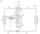
- FIG. 1 is a diagram (part 1) illustrating an example of an overall configuration of a refrigeration cycle device.
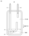
- 4 is a diagram showing an example of an arrangement position of a capacitance type sensor inside an accumulator.
- FIG. FIG. 4 is a diagram illustrating a state in which the flow state of refrigeration oil changes depending on a circulating gas refrigerant flow velocity V.
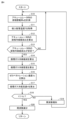
- V is a flowchart (part 1) illustrating an example of a processing procedure of a control device.
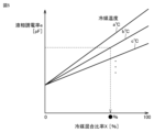
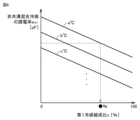
- FIG. 2 is a diagram showing a schematic relationship between a liquid phase dielectric constant e and a refrigerant mixing ratio X.
- FIG. 1 is a diagram (part 1) illustrating an example of an overall configuration of a refrigeration cycle device.
- 4 is a diagram showing an example of an arrangement position of a capacitance type sensor inside an accumulator.
- FIG. 4 is a diagram illustrating a state in which the flow state of refrigeration oil changes depending on a circulating gas refrigerant flow velocity V.
- V is
- FIG. 2 is a diagram illustrating a correspondence relationship between the dielectric constant eref of a non-azeotropic refrigerant mixture and a first refrigerant composition ratio x.
- FIG. 2 is a diagram (part 2) illustrating an example of the overall configuration of a refrigeration cycle device.
- FIG. 4 is a diagram showing an example of an arrangement position of a capacitance type sensor inside an oil separator.
- 13 is a flowchart (part 2) illustrating an example of a processing procedure of the control device.
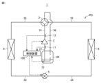
- FIG. 1 is a diagram showing a schematic example of the overall configuration of a refrigeration cycle device 1 according to this embodiment.
- the refrigeration cycle device 1 includes a refrigerant circuit RC in which a non-azeotropic refrigerant mixture circulates, a capacitance-type sensor 10, temperature sensors 11 and 12, and a control device 100.
- the refrigerant circuit RC includes a compressor 2, a four-way valve 3, a first heat exchanger 4, an expansion valve 5, a second heat exchanger 6, an accumulator 20, and pipes 31 to 37 that connect these together.
- Compressor 2 draws in low-pressure refrigerant, compresses it, and discharges it as high-pressure refrigerant. Compressor 2 discharges refrigerant at a flow rate that corresponds to its frequency (rotation speed). Compressor 2 is, for example, an inverter compressor whose frequency (rotation speed) is variable. The flow rate of refrigerant circulating within the refrigerant circuit RC is controlled by adjusting the frequency of compressor 2.
- the compressor 2 contains refrigeration oil capable of dissolving each refrigerant contained in the non-azeotropic refrigerant mixture.
- the refrigeration oil in the compressor 2 acts as a lubricant in the compressor 2.
- the refrigeration oil in the compressor 2 is discharged from the compressor 2 together with the non-azeotropic refrigerant mixture depending on the operating state of the refrigeration cycle device 1, and circulates in the refrigerant circuit RC.
- the non-azeotropic refrigerant mixture used in the refrigeration cycle device 1 according to this embodiment has selective solubility in the refrigeration oil (differences in the solubility of each refrigerant).
- the first heat exchanger 4 is a heat exchanger having a flow path through which the refrigerant flows. In the first heat exchanger 4, heat exchange takes place between the refrigerant flowing inside the flow path and the air outside the flow path.
- the expansion valve 5 is a pressure reducing device that reduces the pressure of the high-pressure refrigerant.
- an electronically controlled expansion valve equipped with a valve body whose opening can be adjusted can be used as the expansion valve 5.
- the second heat exchanger 6 is a heat exchanger having a flow path through which the refrigerant flows. In the second heat exchanger 6, heat exchange takes place between the refrigerant flowing inside the flow path and the air outside the flow path.
- the accumulator 20 is a container that stores the non-azeotropic refrigerant mixture inside, and the non-azeotropic refrigerant mixture is separated into gas and liquid inside the accumulator 20.
- the accumulator 20 corresponds to an example of a "gas-liquid separator" in this disclosure.
- the gas refrigerant separated into gas and liquid in the accumulator 20 is returned to the compressor 2 through the pipe 37.
- the refrigeration cycle device 1 can be operated in a first mode (cooling mode) or a second mode (heating mode) by switching the state of the four-way valve 3.
- the refrigerating machine oil When the flow velocity of the gas refrigerant (hereinafter also referred to as "circulating gas refrigerant") circulating in the piping of the refrigerant circuit is large, the refrigerating machine oil is also lifted up by the flow of the circulating gas refrigerant and rises, and when the flow velocity of the circulating gas refrigerant decreases, the refrigerating machine oil stops rising.
- the flow velocity of the circulating gas refrigerant when the refrigerating machine oil stops rising is called the “zero penetration velocity” and is the limit refrigerant flow velocity of the return oil to the compressor 2. If the zero penetration velocity is VZ , the zero penetration velocity VZ can be calculated as shown in the following formula (1).
- Gr is the refrigerant circulation rate (unit: kg/h)
- A is the cross-sectional area of the pipe (unit: m2 ).
- Figure 3 is a diagram that shows how the flow state of the refrigeration oil changes depending on the circulating gas refrigerant flow velocity V.
- the piping shown in Figure 3 corresponds to any one of the piping 31 to 37 shown in Figure 1.
- the liquid phase in the accumulator 20 contains not only the non-azeotropic refrigerant mixture but also refrigeration oil. Therefore, the composition of the liquid phase in the accumulator 20 changes due to the selective solubility (difference in solubility) of each refrigerant in the refrigeration oil in the liquid phase in the accumulator 20, and this can affect the composition of the circulating gas refrigerant.
- the refrigeration cycle apparatus 1 includes a capacitance sensor 10 and a temperature sensor 11 as detection devices for detecting the composition of the liquid phase in the accumulator 20.
- the control device 100 calculates the refrigerant composition ratio in the liquid phase in the accumulator 20 using the detection results of the capacitance sensor 10 and the temperature sensor 11, thereby accurately calculating the composition of the circulating gas refrigerant in consideration of the amount of excess refrigerant in the accumulator 20 and the selective solubility of each refrigerant.
- the control device 100 uses the calculated composition of the circulating gas refrigerant to control the frequency (rotation speed) of the compressor 2 so that the circulating gas refrigerant flow velocity V becomes equal to or greater than the zero penetration velocity VZ . This makes it possible to appropriately suppress depletion of the refrigeration oil in the compressor 2 while reducing the frequency of the compressor 2 and suppressing the power consumption of the compressor 2.
- FIG. 4 is a flowchart showing an example of a processing procedure of the control device 100. This flowchart is repeatedly executed each time a predetermined condition is met.
- the control device 100 measures the dielectric constant of the liquid phase in the accumulator 20 (hereinafter also referred to as "liquid-phase dielectric constant e") based on the liquid-phase capacitance C detected by the capacitance sensor 10 (step S10).
- the following method for example, can be used to measure the liquid-phase dielectric constant e.
- the liquid-phase capacitance C is expressed by the following equation (3).
- control device 100 acquires the intake pipe temperature T detected by the temperature sensor 11 as a temperature that correlates with the temperature of the liquid phase in the accumulator 20 (step S11).
- control device 100 calculates the refrigerant composition ratio in the liquid phase in the accumulator 20 using the liquid phase dielectric constant e measured in step S10 and the suction pipe temperature T obtained in step S11 (step S12).
- the ratio of the first refrigerant (the sum of the first refrigerant not dissolved in the refrigerant oil and the first refrigerant dissolved in the refrigerant oil) to the entire refrigerant when the entire refrigerant contained in the liquid phase (the sum of the first refrigerant and the second refrigerant not dissolved in the refrigerant oil and the first refrigerant and the second refrigerant dissolved in the refrigerant oil) is set to "1" is calculated as "first refrigerant composition ratio x".
- FIG. 5 is a diagram showing a schematic relationship between the liquid phase dielectric constant e and the refrigerant mixing ratio X.
- the refrigerant mixing ratio X is the ratio of the non-azeotropic refrigerant mixture to the entire liquid phase when the entire liquid phase in the accumulator 20 is set to "1". As shown in FIG. 5, the refrigerant mixing ratio X changes not only with the liquid phase dielectric constant e, but also with the refrigerant temperature (suction pipe temperature T) a°C, b°C, c°C, etc.
- e oil is the dielectric constant of the refrigerating machine oil
- e ref is the dielectric constant of the non-azeotropic refrigerant mixture
- f is a coefficient.
- the control device 100 calculates the refrigerant composition in the gas phase in the accumulator 20 as the composition of the circulating gas refrigerant from the gas-liquid equilibrium relationship based on the refrigerant composition ratio in the liquid phase calculated in step S12 (step S14).
- the control device 100 reduces the frequency of the compressor 2 by a predetermined amount (step S20). This makes it possible to reduce the frequency of the compressor 2 and suppress the power consumption of the compressor 2 within a range that ensures oil return to the compressor 2.
- FIG. 8 is a diagram showing an example of the position of the capacitance sensor 10A inside the oil separator 30.
- the oil separator 30 is disposed on the pipe 31, and separates the gas refrigerant and the refrigeration oil (liquid).
- the refrigeration oil separated by the oil separator 30 stays in the liquid phase (oil phase) portion located vertically below the oil separator 30.
- the oil return pipe 33 is connected to the lower end of the oil separator 30.
- FIG. 9 is a flowchart showing an example of the processing procedure of the control device 100 according to this modified example.
- steps S10 to S14 in the flowchart shown in FIG. 4 above are replaced with steps S10A to S14A.
- the other steps in the flowchart in FIG. 9 (the steps having the same numbers as the steps shown in FIG. 4 above) have already been explained, so detailed explanations will not be repeated here.
- the control device 100 measures the liquid phase dielectric constant in the oil separator 30 based on the liquid phase capacitance in the oil separator 30 detected by the capacitance sensor 10A (step S10A).
- the liquid phase dielectric constant in the oil separator 30 can be measured using a method similar to the method for measuring the liquid phase dielectric constant e in the accumulator 20.
- control device 100 acquires the discharge pipe temperature detected by the temperature sensor 12 as a temperature that correlates with the temperature of the liquid phase in the oil separator 30 (step S11A).
- control device 100 calculates the refrigerant composition ratio in the liquid phase in the oil separator 30 using the liquid phase dielectric constant measured in step S10A and the discharge pipe temperature acquired in step S11A (step S12A).
- the refrigerant composition ratio in the liquid phase in the oil separator 30 can be calculated in the same manner as the refrigerant composition ratio in the liquid phase in the accumulator 20.
- control device 100 determines whether the refrigerant composition ratio in the liquid phase in the oil separator 30 is stable (step S13A). If the refrigerant composition ratio in the liquid phase is not stable (NO in step S13A), the control device 100 returns the process to step S10A and repeats the processes of steps S10A to S13A until the refrigerant composition ratio in the liquid phase is stable.
- control device 100 calculates the refrigerant composition in the gas phase in the oil separator 30 as the composition of the circulating gas refrigerant from the gas-liquid equilibrium relationship based on the refrigerant composition ratio in the liquid phase calculated in step S12A (step S14A).
- step S15 onwards is the same as in the above-described embodiment. That is, the control device 100 calculates the zero penetration speed VZ and the circulating gas refrigerant flow velocity V using the composition of the circulating gas refrigerant calculated in step S14A (steps S15 to S17), and increases or decreases the frequency of the compressor 2 depending on whether the circulating gas refrigerant flow velocity V is higher than the zero penetration speed VZ (steps S18 to S20).
- 1, 1A refrigeration cycle device 2 compressor, 3 four-way valve, 4 first heat exchanger, 5 expansion valve, 6 second heat exchanger, 10, 10A capacitance sensor, 11, 12 temperature sensor, 20 accumulator, 23 oil return hole, 30 oil separator, 31-37 piping, 33 oil return pipe, 100 control device.
Landscapes
- Engineering & Computer Science (AREA)
- Physics & Mathematics (AREA)
- Mechanical Engineering (AREA)
- Thermal Sciences (AREA)
- General Engineering & Computer Science (AREA)
- Compression-Type Refrigeration Machines With Reversible Cycles (AREA)
Abstract
冷凍サイクル装置(1)は、冷媒回路(RC)と、検出装置(10,11)と、制御装置(100)とを備える。冷媒回路(RC)は、非共沸混合冷媒が溶解可能な油が入れられた圧縮機(2)と、第1熱交換器(4)と、膨張弁(5)と、第2熱交換器(6)と、アキュームレータ(20)とを含む。検出装置(10,11)は、アキュームレータ(20)内の液相の組成を検出する。制御装置(100)は、検出装置(10,11)の検出結果を用いて、冷媒回路(RC)内を循環するガス冷媒の流速がゼロペネトレーション速度よりも高くなるように、圧縮機(2)の回転速度を制御する。
Description
本開示は、冷凍サイクル装置に関する。
特開平7-98161号公報(特許文献1)には、冷凍サイクル用の冷媒として、成分の異なる複数種類の冷媒が混合された混合冷媒が用いられる冷凍サイクル装置が開示されている。この冷凍サイクル装置は、圧縮機、第1熱交換器、減圧装置、第2熱交換器、および貯留容器を含む冷媒回路を備えており、貯留容器内には、混合冷媒が溶解可能な冷凍機油が入っている。さらに、この冷凍サイクル装置は、貯留容器内の圧力および温度を調整するための調整装置(開閉弁および加熱装置)を備えており、貯留容器内の圧力および温度を調整することによって、貯留容器内の冷凍機油に溶解している冷媒組成比を制御する。これにより、混合冷媒に含まれる各冷媒の、冷凍機油に対する溶解性の違い(以下「選択的溶解性」とも称する)を利用して、冷媒回路内を循環する冷媒の組成比を制御し、運転条件に対応した好適な冷媒による運転が行なえるようになる。
冷凍サイクル装置の冷媒回路に含まれる圧縮機には、圧縮機内の潤滑剤として作用する冷凍機油が入っている。圧縮機内の冷凍機油は、運転状態に応じて、冷媒と共に圧縮機から吐出されて冷媒回路内を循環する。したがって、圧縮機から吐出されて冷媒回路内を循環する冷凍機油への冷媒の溶解の影響を考慮しないと、冷媒回路内を循環する冷媒の組成比を正確に制御することはできない。
特開平7-98161号公報(特許文献1)に開示された冷凍サイクル装置は、上述のように、貯留容器内の圧力および温度を調整することによって貯留容器内の冷凍機油に溶解している冷媒組成比のみを制御している。すなわち、特開平7-98161号公報(特許文献1)に開示された冷凍サイクル装置は、貯留容器内の冷凍機油への冷媒の溶解の影響のみを考慮し、圧縮機から吐出されて冷媒回路内を循環する冷凍機油への冷媒の溶解の影響については何ら考慮していないため、最適な運転を行うことは難しい。
一般に、混合冷媒は、共沸混合冷媒と、非共沸混合冷媒とに層別される。非共沸混合冷媒が用いられる冷凍サイクル装置において、非共沸混合冷媒が冷凍機油に対する選択的溶解性を有する場合、運転状態および環境条件によって、非共沸混合冷媒に含まれる各冷媒の冷凍機油に対する溶解度(量)が各々独立して変化し、その影響で冷媒回路内を循環する循環ガス冷媒の組成も変化してしまう。循環ガス冷媒の組成が変化すると、循環ガス冷媒の密度が変化するため、循環ガス冷媒の流速が変化する。その影響で、冷凍機油が圧縮機に戻らずに冷媒回路内に滞留してしまい、信頼性悪化につながってしまうことが懸念される。
本開示は、上述の課題を解決するためになされたものであって、その目的は、非共沸混合冷媒が用いられる冷凍サイクル装置において、冷媒回路内に冷凍機油が滞留することを適切に抑制することである。
本開示による冷凍サイクル装置は、非共沸混合冷媒が用いられる冷凍サイクル装置であって、非共沸混合冷媒が溶解可能な油が入れられた圧縮機と、第1熱交換器と、膨張弁と、第2熱交換器と、気液分離器とを含む冷媒回路と、気液分離器内の液相の組成を検出するための検出装置と、検出装置の検出結果を用いて、冷媒回路内を循環するガス冷媒である循環ガス冷媒の流速がゼロペネトレーション速度よりも高くなるように圧縮機の回転速度を制御する制御装置とを備える。
本開示によれば、非共沸混合冷媒が用いられる冷凍サイクル装置において、冷媒回路内に冷凍機油が滞留することを適切に抑制することができる。
以下、本開示の実施の形態について、図面を参照しながら詳細に説明する。なお、図中同一又は相当部分には同一符号を付してその説明は繰り返さない。
図1は、本実施の形態による冷凍サイクル装置1の全体構成の一例を模式的に示す図である。冷凍サイクル装置1は、非共沸混合冷媒が内部を循環する冷媒回路RCと、静電容量式センサ10と、温度センサ11,12と、制御装置100とを備える。冷媒回路RCは、圧縮機2と、四方弁3と、第1熱交換器4と、膨張弁5と、第2熱交換器6と、アキュームレータ20と、これらを接続する配管31~37とを含む。
圧縮機2は、低圧冷媒を吸入して圧縮し、高圧冷媒として吐出する。圧縮機2は、周波数(回転速度)に応じた流量の冷媒を吐出する。圧縮機2は、周波数(回転速度)が可変な、例えばインバータ圧縮機である。冷媒回路RC内を循環する冷媒流量は、圧縮機2の周波数を調整することによって制御される。
圧縮機2には、非共沸混合冷媒に含まれる各冷媒が溶解可能な冷凍機油が入っている。圧縮機2内の冷凍機油は、圧縮機2内の潤滑剤として作用する。圧縮機2内の冷凍機油は、冷凍サイクル装置1の運転状態に応じて、非共沸混合冷媒と共に圧縮機2から吐出されて冷媒回路RC内を循環する。本実施の形態による冷凍サイクル装置1に用いられる非共沸混合冷媒は、冷凍機油に対する選択的溶解性(各冷媒の溶解性の違い)を有する。
第1熱交換器4は、冷媒が流れる流路を有する熱交換器である。第1熱交換器4では、流路の内部を流れる冷媒と、流路の外部の空気との間で熱交換が行われる。
膨張弁5は、高圧冷媒を減圧する減圧装置である。膨張弁5としては、たとえば、開度を調整可能な弁体を備えた電子制御式膨張弁を用いることができる。
第2熱交換器6は、冷媒が流れる流路を有する熱交換器である。第2熱交換器6では、流路の内部を流れる冷媒と、流路の外部の空気との間で熱交換が行われる。
アキュームレータ20は、非共沸混合冷媒を内部に貯留する容器であり、その内部において非共沸混合冷媒が気液分離される。アキュームレータ20は、本開示の「気液分離器」の一例に相当する。アキュームレータ20で気液分離されたガス冷媒は、配管37を通って圧縮機2に戻される。
冷凍サイクル装置1は、四方弁3の状態を切り替えることによって、第1モード(冷房モード)と第2モード(暖房モード)とを切り替えて運転できる。
四方弁3は、圧縮機2の吐出側に設けられている。四方弁3は、圧縮機2の吐出先を第1熱交換器4および第2熱交換器6のどちらかに切替可能に構成されている。四方弁3は、圧縮機2の吐出側を第1熱交換器4に接続するとともに圧縮機2の吸入側を第2熱交換器6に接続する「第1状態」と、圧縮機2の吐出側を第2熱交換器6に接続するとともに圧縮機2の吸入側を第1熱交換器4に接続する「第2状態」と、のいずれかに選択的に制御される。なお、図1には、四方弁3が「第1状態」に制御されている例が示されている。
第1モードでは、四方弁3が第1状態とされ、圧縮機2の吐出側が第1熱交換器4に接続される。第1モードでは、第1熱交換器4は凝縮器として機能するとともに、第2熱交換器6は蒸発器として機能する。第2熱交換器6で熱交換された冷媒は、配管35、四方弁3、配管36をこの順に通ってアキュームレータ20に流入し、アキュームレータ20内において気液分離される。アキュームレータ20内のガス冷媒は、配管37を通って圧縮機2に吸入される。
第2モードでは、四方弁3が第2状態とされ、圧縮機2の吐出側が第2熱交換器6に接続される。第2モードでは、第1熱交換器4は蒸発器として機能するとともに、第2熱交換器6は凝縮器として機能する。第1熱交換器4で熱交換された冷媒は、配管32、四方弁3、配管36をこの順に通ってアキュームレータ20に流入し、アキュームレータ20内において気液分離される。アキュームレータ20内のガス冷媒は、配管37を通って圧縮機2に吸入される。
静電容量式センサ10は、アキュームレータ20内の鉛直下方に位置する液相部分に配置され、アキュームレータ20内の液相の静電容量(以下「液相静電容量C」とも称する)を検出する。静電容量式センサ10は、検出結果(液相静電容量C)を制御装置100に出力する。
図2は、アキュームレータ20の内部における静電容量式センサ10の配置位置の一例を示す図である。冷媒は、配管36からアキュームレータ20の内部に流入し、配管37を通って圧縮機2に戻される。配管36はアキュームレータ20の内部においてI字状に延在する。一方、配管37はアキュームレータ20の内部においてJ字状に延在する。
配管37の先端部(ガス冷媒の入口部)の高さは、液相部分よりも鉛直上方に位置するガス相部分(気相部分)に位置する。配管37の下端部の高さは、液相部分に位置する。配管37の下端部には、液相に含まれる冷凍機油を圧縮機2に戻すための返油穴23が形成されている。
静電容量式センサ10は、液相静電容量Cを確実に検出できるように、アキュームレータ20の内部において液単相になる高さに設置することが望ましい。そのため、本実施の形態においては、静電容量式センサ10が、アキュームレータ20の内部における返油穴23よりも鉛直下方の位置に配置される。
図1に戻って、温度センサ11は、アキュームレータ20から圧縮機2に吸入される冷媒が流れる配管37に配置され、配管37の温度(以下「吸入配管温度T」とも称する)を検出する。温度センサ11は、検出結果(吸入配管温度T)を制御装置100に出力する。なお、配管37はアキュームレータ20内の液相に近いため、本実施の形態においては、温度センサ11によって検出される吸入配管温度Tが、アキュームレータ20内の液相の温度に相関する温度として用いられる。
本実施の形態において、静電容量式センサ10および温度センサ11は、アキュームレータ20内の液相の組成を検出するための検出装置として機能する。なお、アキュームレータ20内の液相温度を直接的に検出する温度センサがある場合には、温度センサ11に代えて当該温度センサを用いるようにしてもよい。
温度センサ12は、圧縮機2から四方弁3に吐出される冷媒が流れる配管31に配置され、配管31の温度(以下「吐出配管温度」ともいう)を検出する。温度センサ12は、検出結果を制御装置100に出力する。
制御装置100は、CPU(Central Processing Unit)と、メモリと、各種信号を入出力するための入出力ポートとを含んで構成される。制御装置100は、各センサ(たとえば静電容量式センサ10および温度センサ11,12など)および機器からの信号、並びにメモリに格納されたプログラムなどに基づいて、冷凍サイクル装置1の各機器(圧縮機2、四方弁3、膨張弁5など)の制御を行なう。なお、制御装置100が行なう制御については、ソフトウェアによる処理に限られず、専用のハードウェア(電子回路)により処理することも可能である。
<ゼロペネトレーション速度>
次に、圧縮機2への返油(冷凍機油の戻し)の限界冷媒流速について説明する。一般に、冷媒回路の配管内においては、冷媒と油とは気液二相で流動し、特に上昇流においてはガス冷媒(気体)の流速によって冷凍機油(液体)の流動状態が変化する。冷媒回路の配管内を循環するガス冷媒(以下「循環ガス冷媒」とも称する)の流速が大きい場合は、冷凍機油も循環ガス冷媒の流れに持ち上げられて上昇し、循環ガス冷媒の流速が減少すると冷凍機油は上昇しなくなる。冷凍機油が上昇しなくなるときの循環ガス冷媒の流速は、「ゼロペネトレーション速度」と呼ばれ、圧縮機2への返油の限界冷媒流速となる。ゼロペネトレーション速度をVZとすると、ゼロペネトレーション速度VZは、下記の式(1)のように算出することができる。
次に、圧縮機2への返油(冷凍機油の戻し)の限界冷媒流速について説明する。一般に、冷媒回路の配管内においては、冷媒と油とは気液二相で流動し、特に上昇流においてはガス冷媒(気体)の流速によって冷凍機油(液体)の流動状態が変化する。冷媒回路の配管内を循環するガス冷媒(以下「循環ガス冷媒」とも称する)の流速が大きい場合は、冷凍機油も循環ガス冷媒の流れに持ち上げられて上昇し、循環ガス冷媒の流速が減少すると冷凍機油は上昇しなくなる。冷凍機油が上昇しなくなるときの循環ガス冷媒の流速は、「ゼロペネトレーション速度」と呼ばれ、圧縮機2への返油の限界冷媒流速となる。ゼロペネトレーション速度をVZとすると、ゼロペネトレーション速度VZは、下記の式(1)のように算出することができる。

式(1)において、「g」は重力加速度(単位:m/s2)、「d」は配管の内径(単位:m)、「Dref_g」は循環ガス冷媒密度(単位:kg/m3)、「Doil」は冷凍機油密度(単位:kg/m3)、「C」は冷媒および配管形状で決まる定数である。
一方、循環ガス冷媒の流速を「循環ガス冷媒流速V」とすると、循環ガス冷媒流速Vは下記の式(2)のように算出することができる。

式(2)において、「Gr」は冷媒循環量(単位:kg/h)、「A」は配管の断面積(単位:m2)である。
図3は、循環ガス冷媒流速Vによって冷凍機油の流動状態が変化する様子を模式的に示す図である。なお、図3に示す配管は、図1に示す配管31~37のいずれかに相当する。
循環ガス冷媒流速Vがゼロペネトレーション速度VZよりも高いときは、図3の左側に示すように、循環ガス冷媒の流れと共に冷凍機油も流れるため、冷凍機油は配管内に滞留することなく循環する。これにより圧縮機2に返油することができ、圧縮機2の信頼性が担保される。
一方、循環ガス冷媒流速Vがゼロペネトレーション速度VZよりも低いときは、図3の右側に示すように、循環ガス冷媒が流れても冷凍機油が流れなくなるため、配管内に滞留する冷凍機油の量が急増する。これにより、圧縮機2への返油量が低下し、圧縮機2の油枯渇が生じる恐れがある。
そのため、本実施の形態においては、以下に説明するように、非共沸混合冷媒の冷凍機油に対する選択的溶解性の影響を考慮した上で、循環ガス冷媒流速Vがゼロペネトレーション速度VZ以上になるように圧縮機2の周波数(回転速度)を制御する。これにより、圧縮機2への返油量を確保し、圧縮機2の油枯渇を適切に抑制することができる。
<圧縮機2の周波数制御>
本実施の形態による冷凍サイクル装置1のように非共沸混合冷媒が冷凍機油に対する選択的溶解性を有する場合、冷凍サイクル装置1の運転状態および環境条件によって、各冷媒が冷凍機油に溶解する量が変化し、その影響で循環ガス冷媒の組成比も変化してしまう。循環ガス冷媒の組成比が変化すると、循環ガス冷媒の密度が変化するため、循環ガス冷媒流速Vが変化する。その影響で循環ガス冷媒流速Vがゼロペネトレーション速度VZよりも低くなってしまうと、圧縮機2への返油性が悪化して冷凍機油が冷媒回路RC内に滞留してしまい、信頼性悪化につながってしまうことが懸念される。
本実施の形態による冷凍サイクル装置1のように非共沸混合冷媒が冷凍機油に対する選択的溶解性を有する場合、冷凍サイクル装置1の運転状態および環境条件によって、各冷媒が冷凍機油に溶解する量が変化し、その影響で循環ガス冷媒の組成比も変化してしまう。循環ガス冷媒の組成比が変化すると、循環ガス冷媒の密度が変化するため、循環ガス冷媒流速Vが変化する。その影響で循環ガス冷媒流速Vがゼロペネトレーション速度VZよりも低くなってしまうと、圧縮機2への返油性が悪化して冷凍機油が冷媒回路RC内に滞留してしまい、信頼性悪化につながってしまうことが懸念される。
また、非共沸混合冷媒の余剰分が液相となってアキュームレータ20に溜まると、アキュームレータ20の液相には、高沸点の冷媒がより多く溶解することが知られている。したがって、アキュームレータ20内の余剰冷媒量が多いほど、循環ガス冷媒の組成比は、低沸点の冷媒組成比が高くなる方向に変化する。例えばR32とR1234yfとの非共沸混合冷媒が用いられる場合は、アキュームレータ20内の余剰冷媒量が多いほど余剰冷媒に溶け込む高沸点のR1234yfの量が多くなるため、その分、循環ガス冷媒には低沸点のR32がより多く含まれることになる。
さらに、アキュームレータ20内の液相には、非共沸混合冷媒だけでなく、冷凍機油が含まれている。そのため、アキュームレータ20内の液相中の冷凍機油に対する各冷媒の選択的溶解性(溶解度の違い)に起因してアキュームレータ20内の液相の組成が変化し、その影響で循環ガス冷媒の組成も変化し得る。
以上の点を踏まえ、本実施の形態による冷凍サイクル装置1は、アキュームレータ20内の液相の組成を検出するための検出装置として、静電容量式センサ10と、温度センサ11とを備える。そして、制御装置100は、静電容量式センサ10および温度センサ11の検出結果を用いてアキュームレータ20内の液相中の冷媒組成比を算出することで、アキュームレータ20内の余剰冷媒量および各冷媒の選択的溶解性を考慮して、循環ガス冷媒の組成を精度よく算出する。そして、制御装置100は、算出された循環ガス冷媒の組成を用いて、循環ガス冷媒流速Vがゼロペネトレーション速度VZ以上になるように圧縮機2の周波数(回転速度)を制御する。これにより、圧縮機2内の冷凍機油の枯渇を適切に抑制しつつ、圧縮機2の周波数を低下させて圧縮機2の消費電力を抑制することができる。
図4は、制御装置100の処理手順の一例を示すフローチャートである。このフローチャートは、予め定められた条件が成立する毎に繰り返し実行される。
制御装置100は、静電容量式センサ10によって検出された液相静電容量Cに基づいて、アキュームレータ20内の液相の誘電率(以下「液相誘電率e」とも称する)を計測する(ステップS10)。液相誘電率eの計測手法として、たとえば以下の手法を採用することができる。液相静電容量Cは下記の式(3)によって表わされる。
C=e0×es×(S/L)=e×(S/L) …(3)
式(3)において、「e0」は真空中の誘電率(一般的には8.854×10⁻¹²)、「es」は液相の比誘電率、「S」は静電容量式センサ10の電極面積、「L」は静電容量式センサ10の電極間距離である。S,Lは定数であるため、制御装置100は、静電容量式センサ10によって検出された液相静電容量Cを式(3)に代入することによって液相誘電率e(=e0×es)を計測することができる。
式(3)において、「e0」は真空中の誘電率(一般的には8.854×10⁻¹²)、「es」は液相の比誘電率、「S」は静電容量式センサ10の電極面積、「L」は静電容量式センサ10の電極間距離である。S,Lは定数であるため、制御装置100は、静電容量式センサ10によって検出された液相静電容量Cを式(3)に代入することによって液相誘電率e(=e0×es)を計測することができる。
次いで、制御装置100は、アキュームレータ20内の液相の温度に相関する温度として、温度センサ11によって検出された吸入配管温度Tを取得する(ステップS11)。
次いで、制御装置100は、ステップS10で計測された液相誘電率eとステップS11で取得された吸入配管温度Tとを用いて、アキュームレータ20内の液相中の冷媒組成比を算出する(ステップS12)。
以下、アキュームレータ20内の液相中の冷媒組成比の算出手法の一例を具体的に説明する。以下では、非共沸混合冷媒の一例として、互いに成分の異なる第1冷媒と第2冷媒との非共沸混合冷媒を用いる場合について説明する。また、以下では、アキュームレータ20内の液相中の冷媒組成比の一例として、液相中に含まれる冷媒全体(冷凍機油に溶解していない第1冷媒および第2冷媒と、冷凍機油に溶解している第1冷媒および第2冷媒との合計)を「1」としたときの、冷媒全体に対する第1冷媒(冷凍機油に溶解していない第1冷媒と、冷凍機油に溶解している第1冷媒との合計)の比率を「第1冷媒組成比x」として算出する例について説明する。
図5は、液相誘電率eと冷媒混合比率Xとの対応関係を模式的に示す図である。冷媒混合比率Xは、アキュームレータ20内の液相全体を「1」としたときの、液相全体に対する非共沸混合冷媒の比率である。図5に示されるように、冷媒混合比率Xは、液相誘電率eだけでなく、冷媒温度(吸入配管温度T)a℃、b℃、c℃…によっても変化する。
液相の比誘電率esは、下記の式(4)の近似式で表わすことができる。式(4)において、「eoil」は冷凍機油の誘電率、「eref」は非共沸混合冷媒の誘電率、「f」は係数である。
es=eoil(1-X)+erefX+f …(4)
冷凍機油の誘電率eoilは、非共沸混合冷媒の誘電率erefと比較して小さく、さらに温度依存性がないことが知られているため、油の種類によって決まる定数と考えてよい。
冷凍機油の誘電率eoilは、非共沸混合冷媒の誘電率erefと比較して小さく、さらに温度依存性がないことが知られているため、油の種類によって決まる定数と考えてよい。
さらに、非共沸混合冷媒の誘電率erefは、液相誘電率eと冷媒混合比率Xとを用いて、下記の式(5)で表わすことができる。
eref=eX …(5)
図6は、非共沸混合冷媒の誘電率eref(=eX)と第1冷媒組成比xとの対応関係を模式的に示す図である。図6に示されるように、第1冷媒組成比xは、液相中の第1冷媒の誘電率だけでなく、第1冷媒の温度によっても変化する。
図6は、非共沸混合冷媒の誘電率eref(=eX)と第1冷媒組成比xとの対応関係を模式的に示す図である。図6に示されるように、第1冷媒組成比xは、液相中の第1冷媒の誘電率だけでなく、第1冷媒の温度によっても変化する。
さらに、非共沸混合冷媒の誘電率erefは、液相中の第1冷媒の誘電率をeAとし、第2冷媒の誘電率をeBとすると、下記の式(6)の近似式で表わすことができる。
eref=eAx+eB(1-x) …(6)
さらに、各冷媒の誘電率eA,eBは、各冷媒温度によって変化するため、それぞれ下記の式(7),(8)で表わすことができる。式(7),(8)において、k1~k4は近似式の定数である。
さらに、各冷媒の誘電率eA,eBは、各冷媒温度によって変化するため、それぞれ下記の式(7),(8)で表わすことができる。式(7),(8)において、k1~k4は近似式の定数である。
eA=k1T+k2 …(7)
eB=k3T+k4 …(8)
制御装置100は、ステップS10で計測された液相誘電率e、ステップS11で取得された吸入配管温度T、および上記の式(4)~(8)を用いて、第1冷媒組成比x(アキュームレータ20内の液相中の冷媒組成比)を算出する。
eB=k3T+k4 …(8)
制御装置100は、ステップS10で計測された液相誘電率e、ステップS11で取得された吸入配管温度T、および上記の式(4)~(8)を用いて、第1冷媒組成比x(アキュームレータ20内の液相中の冷媒組成比)を算出する。
次いで、制御装置100は、アキュームレータ20内の液相中の冷媒組成比が安定したか否かを判定する(ステップS13)。たとえば、制御装置100は、直近の予め定められた時間内に算出された液相中の冷媒組成比の変動幅が予め定められた基準値よりも小さい場合に、液相中の冷媒組成比が安定したと判定する。液相中の冷媒組成比が安定していない場合(ステップS13においてNO)、制御装置100は、処理をステップS10に戻し、液相中の冷媒組成比が安定するまでステップS10~S13の処理を繰り返す。
液相中の冷媒組成比が安定している場合(ステップS13においてYES)、制御装置100は、ステップS12で算出された液相中の冷媒組成比に基づいて、気液平衡の関係よりアキュームレータ20内の気相中の冷媒組成を循環ガス冷媒の組成として算出する(ステップS14)。
次いで、制御装置100は、ステップS14で算出された循環ガス冷媒の組成に基づいて、循環ガス冷媒密度Dref_gを算出する(ステップS15)。
次いで、制御装置100は、ステップS15で算出された循環ガス冷媒密度Dref_gと、上記の式(1)とを用いて、ゼロペネトレーション速度VZを算出する(ステップS16)。
次いで、制御装置100は、ステップS15で算出された循環ガス冷媒密度Dref_gと、圧縮機2の周波数から求まる冷媒循環量Grと、上記の式(2)とを用いて、循環ガス冷媒流速Vを算出する(ステップS17)。
次いで、制御装置100は、循環ガス冷媒流速Vがゼロペネトレーション速度VZよりも高いか否かを判定する(ステップS18)。
循環ガス冷媒流速Vがゼロペネトレーション速度VZよりも低い場合(ステップS18においてNO)、制御装置100は、圧縮機2の周波数を予め定められた量だけ増加させる(ステップS19)。その後、制御装置100は、処理をステップS10に戻し、循環ガス冷媒流速Vがゼロペネトレーション速度VZよりも高くなるまで圧縮機2の周波数を予め定められた量ずつ増加させる処理を繰り返す。これにより、圧縮機2への返油性を向上させて、圧縮機2内の冷凍機油の枯渇を適切に抑制することができる。
一方、循環ガス冷媒流速Vがゼロペネトレーション速度VZよりも高い場合(ステップS18においてYES)、制御装置100は、圧縮機2の周波数を予め定められた量だけ減少させる(ステップS20)。これにより、圧縮機2への返油性を確保できる範囲で、圧縮機2の周波数を低下させて圧縮機2の消費電力を抑制することができる。
以上のように、本実施の形態による冷凍サイクル装置1によれば、アキュームレータ20内の余剰冷媒量が変化し、かつ非共沸混合冷媒に含まれる各冷媒が冷凍機油への選択的溶解性を有する場合であっても、循環ガス冷媒組成の変化に応じて循環ガス冷媒流速Vおよびゼロペネトレーション速度VZが算出され、循環ガス冷媒流速Vがゼロペネトレーション速度VZ以上になるように圧縮機2の周波数が制御される。これにより、冷媒回路内の配管中に冷凍機油が滞留することを抑制して、圧縮機2への冷凍機油の返油性を向上させることができる。
[変形例]
図7は、本変形例による冷凍サイクル装置1Aの全体構成の一例を模式的に示す図である。冷凍サイクル装置1Aは、上述の冷凍サイクル装置1に対して、オイルセパレータ30および返油管33を追加し、さらに静電容量式センサ10に代えて静電容量式センサ10Aを設けたものである。冷凍サイクル装置1Aのその他の構成は、上述の冷凍サイクル装置1と同じである。
図7は、本変形例による冷凍サイクル装置1Aの全体構成の一例を模式的に示す図である。冷凍サイクル装置1Aは、上述の冷凍サイクル装置1に対して、オイルセパレータ30および返油管33を追加し、さらに静電容量式センサ10に代えて静電容量式センサ10Aを設けたものである。冷凍サイクル装置1Aのその他の構成は、上述の冷凍サイクル装置1と同じである。
オイルセパレータ30は、圧縮機2の吐出口と四方弁3とを接続する配管31上に配置され、圧縮機2によって圧縮されたガス冷媒と、ガス冷媒と共に圧縮機2から吐出された冷凍機油(液体)とを分離する。返油管33は、オイルセパレータ30の下方部分と配管36とに接続される。オイルセパレータ30でガス冷媒と分離された冷凍機油は、返油管33を通って配管36に戻される。
静電容量式センサ10Aは、オイルセパレータ30内の鉛直下方に位置する液相(油相)部分に配置され、オイルセパレータ30内の液相の静電容量を検出する。静電容量式センサ10Aは、検出結果を制御装置100に出力する。
図8は、オイルセパレータ30の内部における静電容量式センサ10Aの配置位置の一例を示す図である。上述のように、オイルセパレータ30は、配管31上に配置され、ガス冷媒と冷凍機油(液体)とを分離する。オイルセパレータ30で分離された冷凍機油は、オイルセパレータ30の鉛直下方に位置する液相(油相)部分に滞留する。返油管33は、オイルセパレータ30の下端に接続される。
静電容量式センサ10Aは、オイルセパレータ30内の液相の静電容量を確実に検出できるように、オイルセパレータ30内の下端部分に配置される。
以上のように、オイルセパレータ30のようなガス冷媒と冷凍機油とを分離する気液分離器がある場合、オイルセパレータ30内の下部の液相部分(油滞留部)に静電容量式センサ10Aを設けるようにしてもよい。
本変形例によるオイルセパレータ30は、本開示の「気液分離器」の一例に相当する。また、配管31はオイルセパレータ30内の液相に近いため、本変形例においては、温度センサ12によって検出される配管31の温度(吐出配管温度)が、オイルセパレータ30内の液相の温度に相関する温度として用いられる。すなわち、本変形例において、静電容量式センサ10Aおよび温度センサ12は、オイルセパレータ30内の液相の組成を検出するための検出装置として機能する。なお、オイルセパレータ30内の液相温度を直接的に検出する温度センサがある場合には、温度センサ12に代えて当該温度センサを用いるようにしてもよい。
図9は、本変形例による制御装置100の処理手順の一例を示すフローチャートである。このフローチャートは、上述の図4に示すフローチャートのステップS10~S14を、ステップS10A~S14Aに変更したものである。図9のフローチャートのその他のステップ(上述の図4に示したステップと同じ番号を付しているステップ)については、既に説明したため詳細な説明はここでは繰り返さない。
制御装置100は、静電容量式センサ10Aによって検出されたオイルセパレータ30内の液相静電容量に基づいて、オイルセパレータ30内の液相誘電率を計測する(ステップS10A)。オイルセパレータ30内の液相誘電率は、アキュームレータ20内の液相誘電率eの計測手法と同様の手法で計測することができる。
次いで、制御装置100は、オイルセパレータ30内の液相の温度に相関する温度として、温度センサ12によって検出された吐出配管温度を取得する(ステップS11A)。
次いで、制御装置100は、ステップS10Aで計測された液相誘電率とステップS11Aで取得された吐出配管温度とを用いて、オイルセパレータ30内の液相中の冷媒組成比を算出する(ステップS12A)。オイルセパレータ30内の液相中の冷媒組成比は、アキュームレータ20内の液相中の冷媒組成比と同様の手法で算出することができる。
次いで、制御装置100は、オイルセパレータ30内の液相中の冷媒組成比が安定したか否かを判定する(ステップS13A)。液相中の冷媒組成比が安定していない場合(ステップS13AにおいてNO)、制御装置100は、処理をステップS10Aに戻し、液相中の冷媒組成比が安定するまでステップS10A~S13Aの処理を繰り返す。
液相中の冷媒組成比が安定している場合(ステップS13AにおいてNO)、制御装置100は、ステップS12Aで算出された液相中の冷媒組成比に基づいて、気液平衡の関係よりオイルセパレータ30内の気相中の冷媒組成を循環ガス冷媒の組成として算出する(ステップS14A)。
ステップS15以降の処理については、上述の実施の形態と同様である。すなわち、制御装置100は、ステップS14Aで算出された循環ガス冷媒の組成を用いてゼロペネトレーション速度VZおよび循環ガス冷媒流速Vを算出し(ステップS15~S17)、循環ガス冷媒流速Vがゼロペネトレーション速度VZよりも高いか否かに応じて圧縮機2の周波数を増減させる(ステップS18~S20)。
以上のように、冷媒回路中にガス冷媒と冷凍機油とを分離するオイルセパレータ30が備えられる場合には、オイルセパレータ30内の液相(冷凍機油)に溶解している冷媒組成を計測することにより、オイルセパレータ30内の液相に溶解していないガス冷媒(循環ガス冷媒)の組成をより正確に算出することができる。その結果、上述の実施の形態と同様の作用効果を奏しつつ、上述の実施の形態よりも制御応答性を高めることができる。
今回開示された実施の形態はすべての点で例示であって制限的なものではないと考えられるべきである。本開示の範囲は上記した説明ではなくて請求の範囲によって示され、請求の範囲と均等の意味および範囲内でのすべての変更が含まれることが意図される。
1,1A 冷凍サイクル装置、2 圧縮機、3 四方弁、4 第1熱交換器、5 膨張弁、6 第2熱交換器、10,10A 静電容量式センサ、11,12 温度センサ、20 アキュームレータ、23 返油穴、30 オイルセパレータ、31~37 配管、33 返油管、100 制御装置。
Claims (6)
- 非共沸混合冷媒が用いられる冷凍サイクル装置であって、
前記非共沸混合冷媒が溶解可能な油が入れられた圧縮機と、第1熱交換器と、膨張弁と、第2熱交換器と、気液分離器とを含む冷媒回路と、
前記気液分離器内の液相の組成を検出するための検出装置と、
前記検出装置の検出結果を用いて、前記冷媒回路内を循環するガス冷媒である循環ガス冷媒の流速がゼロペネトレーション速度よりも高くなるように、前記圧縮機の回転速度を制御する制御装置とを備える、冷凍サイクル装置。 - 前記検出装置は、
前記気液分離器内の液相の静電容量を検出する静電容量式センサと、
前記気液分離器内の液相の温度、あるいは前記気液分離器内の液相の温度に相関する温度を検出する温度センサとを含む、請求項1に記載の冷凍サイクル装置。 - 前記制御装置は、
前記検出装置の検出結果を用いて前記気液分離器内の液相中の冷媒組成比を算出し、
前記気液分離器内の液相中の冷媒組成比を用いて前記循環ガス冷媒の組成比を算出し、
前記循環ガス冷媒の組成比を用いて前記循環ガス冷媒の密度を算出し、
前記循環ガス冷媒の密度を用いてゼロペネトレーション速度を算出し、
前記循環ガス冷媒の密度と前記圧縮機の周波数とを用いて前記循環ガス冷媒の流速を算出し、
前記循環ガス冷媒の流速が前記ゼロペネトレーション速度よりも低い場合に前記圧縮機の周波数を増加させる、請求項2に記載の冷凍サイクル装置。 - 前記制御装置は、
前記検出装置の検出結果を用いて前記気液分離器内の液相中の冷媒と油との混合比率を算出し、
前記検出装置の検出結果および前記混合比率を用いて前記気液分離器内の液相中の冷媒組成比を算出する、請求項3に記載の冷凍サイクル装置。 - 前記気液分離器は、前記圧縮機の吸入口に接続されたアキュームレータであり、
前記アキュームレータは、前記アキュームレータ内の液相中の油を前記圧縮機に戻すための返油穴を有し、
前記静電容量式センサは、前記アキュームレータにおける前記返油穴よりも鉛直下方の位置に設置される、請求項2に記載の冷凍サイクル装置。 - 前記気液分離器は、前記圧縮機の吐出口に接続されたオイルセパレータであり、
前記オイルセパレータの下端には、前記オイルセパレータ内の油を前記圧縮機に戻すための返油管が接続され、
前記静電容量式センサは、前記オイルセパレータの下端に設置される、請求項2に記載の冷凍サイクル装置。
Priority Applications (1)
| Application Number | Priority Date | Filing Date | Title |
|---|---|---|---|
| PCT/JP2023/021557 WO2024252671A1 (ja) | 2023-06-09 | 2023-06-09 | 冷凍サイクル装置 |
Applications Claiming Priority (1)
| Application Number | Priority Date | Filing Date | Title |
|---|---|---|---|
| PCT/JP2023/021557 WO2024252671A1 (ja) | 2023-06-09 | 2023-06-09 | 冷凍サイクル装置 |
Publications (1)
| Publication Number | Publication Date |
|---|---|
| WO2024252671A1 true WO2024252671A1 (ja) | 2024-12-12 |
Family
ID=93795238
Family Applications (1)
| Application Number | Title | Priority Date | Filing Date |
|---|---|---|---|
| PCT/JP2023/021557 Ceased WO2024252671A1 (ja) | 2023-06-09 | 2023-06-09 | 冷凍サイクル装置 |
Country Status (1)
| Country | Link |
|---|---|
| WO (1) | WO2024252671A1 (ja) |
Cited By (1)
| Publication number | Priority date | Publication date | Assignee | Title |
|---|---|---|---|---|
| CN120351125A (zh) * | 2025-06-25 | 2025-07-22 | 烟台珈群高效节能设备有限公司 | 压缩机制冷系统中的润滑油冷却子系统 |
Citations (6)
| Publication number | Priority date | Publication date | Assignee | Title |
|---|---|---|---|---|
| JPH07208835A (ja) * | 1994-01-17 | 1995-08-11 | Hitachi Ltd | 冷凍空調装置 |
| JPH1068555A (ja) * | 1996-08-27 | 1998-03-10 | Mitsubishi Heavy Ind Ltd | 冷凍サイクルの循環冷媒組成検出方法並びにその検出方法を用いた冷凍装置 |
| JP2006038318A (ja) * | 2004-07-26 | 2006-02-09 | Mitsubishi Electric Corp | 空気調和機 |
| JP2012215357A (ja) * | 2011-04-01 | 2012-11-08 | Mitsubishi Electric Corp | 冷凍機 |
| WO2014196045A1 (ja) * | 2013-06-06 | 2014-12-11 | 三菱電機株式会社 | 冷凍サイクル装置 |
| WO2017221300A1 (ja) * | 2016-06-20 | 2017-12-28 | 三菱電機株式会社 | 空気調和装置 |
-
2023
- 2023-06-09 WO PCT/JP2023/021557 patent/WO2024252671A1/ja not_active Ceased
Patent Citations (6)
| Publication number | Priority date | Publication date | Assignee | Title |
|---|---|---|---|---|
| JPH07208835A (ja) * | 1994-01-17 | 1995-08-11 | Hitachi Ltd | 冷凍空調装置 |
| JPH1068555A (ja) * | 1996-08-27 | 1998-03-10 | Mitsubishi Heavy Ind Ltd | 冷凍サイクルの循環冷媒組成検出方法並びにその検出方法を用いた冷凍装置 |
| JP2006038318A (ja) * | 2004-07-26 | 2006-02-09 | Mitsubishi Electric Corp | 空気調和機 |
| JP2012215357A (ja) * | 2011-04-01 | 2012-11-08 | Mitsubishi Electric Corp | 冷凍機 |
| WO2014196045A1 (ja) * | 2013-06-06 | 2014-12-11 | 三菱電機株式会社 | 冷凍サイクル装置 |
| WO2017221300A1 (ja) * | 2016-06-20 | 2017-12-28 | 三菱電機株式会社 | 空気調和装置 |
Cited By (1)
| Publication number | Priority date | Publication date | Assignee | Title |
|---|---|---|---|---|
| CN120351125A (zh) * | 2025-06-25 | 2025-07-22 | 烟台珈群高效节能设备有限公司 | 压缩机制冷系统中的润滑油冷却子系统 |
Similar Documents
| Publication | Publication Date | Title |
|---|---|---|
| CN101901017B (zh) | 节流机构的模糊控制系统及方法 | |
| US7647784B2 (en) | Refrigeration device and method for detecting refrigerant amount of refrigeration device | |
| KR100325927B1 (ko) | 냉동공조장치및냉동공조장치의냉매조성을구하는방법 | |
| US9752815B2 (en) | Method of controlling heat source-side heat exchanger fan, and air conditioner | |
| JP2011255831A (ja) | 車両用空調装置及び車両用空調装置の冷媒漏出診断方法 | |
| US20150185197A1 (en) | Method for measuring dilution and viscosity of lubricating oil, control method and control module, and refrigeration air conditioning system | |
| EP2730863B1 (en) | Refrigeration and air conditioning device and method for controlling refrigeration and air conditioning device | |
| CN105674638A (zh) | 气液分离器、空调系统及防压缩机回液的控制方法 | |
| JP6785974B2 (ja) | 空気調和装置 | |
| Wang et al. | Design of experimental bench and internal pressure measurement of scroll compressor with refrigerant injection | |
| JP2018185116A (ja) | 冷凍サイクル装置 | |
| WO2024252671A1 (ja) | 冷凍サイクル装置 | |
| JPH0996618A (ja) | 冷媒量検出装置および冷媒状態検出装置 | |
| CN107388514A (zh) | 空调器及其能效计算方法 | |
| CN114593497B (zh) | 旁通回路冷媒流量检测方法、装置、系统及存储介质 | |
| JPH10253203A (ja) | 冷媒回収方法 | |
| JPH1068555A (ja) | 冷凍サイクルの循環冷媒組成検出方法並びにその検出方法を用いた冷凍装置 | |
| WO2016046876A1 (ja) | 冷凍サイクル装置 | |
| CN107208951B (zh) | 制冷剂量异常检测装置以及制冷装置 | |
| CN110173936B (zh) | 用于控制蒸发器内的液体水平的方法及其系统 | |
| CN114857760B (zh) | 空调机组 | |
| WO2020066001A1 (ja) | 冷凍サイクル装置 | |
| JP2000321103A (ja) | 冷凍用圧縮機の試験装置 | |
| CN113203214B (zh) | 制冷系统 | |
| WO2020065999A1 (ja) | 冷凍サイクル装置の室外機、冷凍サイクル装置、及び空気調和装置 |
Legal Events
| Date | Code | Title | Description |
|---|---|---|---|
| 121 | Ep: the epo has been informed by wipo that ep was designated in this application |
Ref document number: 23940769 Country of ref document: EP Kind code of ref document: A1 |
|
| NENP | Non-entry into the national phase |
Ref country code: DE |