WO2024252591A1 - 管理装置、管理方法及びプログラム - Google Patents
管理装置、管理方法及びプログラム Download PDFInfo
- Publication number
- WO2024252591A1 WO2024252591A1 PCT/JP2023/021239 JP2023021239W WO2024252591A1 WO 2024252591 A1 WO2024252591 A1 WO 2024252591A1 JP 2023021239 W JP2023021239 W JP 2023021239W WO 2024252591 A1 WO2024252591 A1 WO 2024252591A1
- Authority
- WO
- WIPO (PCT)
- Prior art keywords
- storage battery
- power source
- soc
- measurement value
- power
- Prior art date
- Legal status (The legal status is an assumption and is not a legal conclusion. Google has not performed a legal analysis and makes no representation as to the accuracy of the status listed.)
- Ceased
Links
Images


Classifications
-
- H—ELECTRICITY
- H01—ELECTRIC ELEMENTS
- H01M—PROCESSES OR MEANS, e.g. BATTERIES, FOR THE DIRECT CONVERSION OF CHEMICAL ENERGY INTO ELECTRICAL ENERGY
- H01M10/00—Secondary cells; Manufacture thereof
- H01M10/42—Methods or arrangements for servicing or maintenance of secondary cells or secondary half-cells
- H01M10/48—Accumulators combined with arrangements for measuring, testing or indicating the condition of cells, e.g. the level or density of the electrolyte
-
- H—ELECTRICITY
- H02—GENERATION; CONVERSION OR DISTRIBUTION OF ELECTRIC POWER
- H02J—ELECTRIC POWER NETWORKS; CIRCUIT ARRANGEMENTS OR SYSTEMS FOR SUPPLYING OR DISTRIBUTING ELECTRIC POWER; SYSTEMS FOR STORING ELECTRIC ENERGY
- H02J7/00—Circuit arrangements for charging or discharging batteries or for supplying loads from batteries
Definitions
- This disclosure relates to a management device, a management method, and a program.
- VPP virtual power plant
- a virtual power plant can integrate and control electricity from various power sources, such as solar power, wind power, hydroelectric power, thermal power, and nuclear power, and store the electricity from these sources in a storage battery.
- the power source is clarified by measuring the input and output power of the storage battery, but the remaining charge of the storage battery itself is not measured.
- the remaining charge of the storage battery itself is not measured.
- This disclosure was made in consideration of the above points, and provides technology that can accurately manage the remaining charge of each power source.
- the management device is a management device that manages the remaining capacity of a storage battery at each time for each power source, and has an acquisition unit that acquires, at the current time, a first measurement value that measures the remaining capacity of the storage battery, a second measurement value that measures the amount of charge to the storage battery for each power source, and a third measurement value that measures the amount of discharge from the storage battery; a first calculation unit that calculates the amount of discharge from the storage battery for each power source based on the third measurement value; and a second calculation unit that calculates the remaining capacity of the power source by correcting, for each power source, the value obtained by subtracting the amount of discharge of the power source from the sum of the remaining capacity of the power source in the storage battery one time ago and the second measurement value of the power source, based on the first measurement value, the second measurement value for each power source, the remaining capacity of each power source in the storage battery one time ago, and the discharge amount of each power source, using a relationship that indicates that the first measurement value is equal to the sum of the sum of the
- FIG. 2 is a diagram illustrating an example of the overall configuration of a control device according to the present embodiment.
- FIG. 2 is a diagram illustrating an example of the configuration of a storage battery according to the present embodiment.
- FIG. 2 is a diagram illustrating an example of a hardware configuration of a control device according to the present embodiment.
- 10 is a flowchart illustrating an example of a remaining amount management process according to the embodiment.
- a control device 10 that can control the supply of power from multiple power sources in a virtual power plant equipped with a storage battery that stores the power from the multiple power sources, and can accurately manage the remaining power of each power source.
- Fig. 1 is a diagram showing an example of the overall configuration of a control device 10 according to this embodiment.
- the control device 10 is a computer or computer system that is connected to multiple power sources and has a storage battery 201 that stores power from the multiple power sources.
- N the number of power sources
- power source 1 the number of power sources
- power source 2 the number of power sources
- power sources such as solar power generation, wind power generation, hydroelectric power generation, thermal power generation, and nuclear power generation.
- power source 1 is a power source derived from a grid
- power source 2 is a power source derived from renewable energy (hereinafter also referred to as "renewable energy” for short).
- examples of power sources derived from a grid include thermal power generation and nuclear power generation.
- power sources derived from renewable energy include solar power generation, wind power generation, and hydroelectric power generation.
- the control device 10 also supplies the power stored in the storage battery 201 in response to receiving a request from the server 20 to request the required power.
- the request specifies the amount of power required (requested power amount) and the ratio or rate of the amount of power derived from "renewable energy” in the requested amount of power (hereinafter referred to as the "renewable energy ratio").
- the requested amount of power "a [kW]” and the renewable energy ratio "0.5" are specified in the request. This means that half of the requested amount of power a [kW] is requested to be derived from "renewable energy” and the rest is requested to be derived from the "grid”.
- the request may specify, for example, the ratio (proportion) of the amount of power derived from each power source to the requested amount of power instead of the renewable energy ratio.
- the request may specify the time when the requested amount of power is required (request time).
- control device 10 has a communication unit 101, a storage battery control unit 102, a remaining capacity management unit 103, and a memory unit 104.
- the communication unit 101 receives a request from the server 20 via a communication network (e.g., a LAN (Local Area Network), a mobile phone network, the Internet, etc.).
- a communication network e.g., a LAN (Local Area Network), a mobile phone network, the Internet, etc.
- the battery control unit 102 controls the battery 201 to output (discharge) the requested amount of power specified in the request.
- the remaining amount management unit 103 calculates the amount of stored electricity (remaining amount) from each power source for each source of power (i.e., "grid” or “renewable energy”) and stores the calculated amount in the memory unit 104.
- the memory unit 104 stores information indicating the amount of stored power (remaining power) for each power source, as well as various other information.
- Fig. 2 is a diagram showing an example of the configuration of the storage battery 201 according to this embodiment.
- the storage battery 201 has a power storage unit 211, N input measurement units 212, an output measurement unit 213, and a remaining capacity measurement unit 214.
- the power storage unit 211 stores the power input from each of the power sources 1 to N.
- the power storage unit 211 also discharges the power to the power transmission and distribution network according to the control of the battery control unit 102.
- the input measurement unit 212 is realized by a power meter such as an integrator, and for each predetermined time interval ⁇ t, it measures the cumulative value of the amount of power (i.e., the amount of charge) of the power input from the power source corresponding to the input measurement unit 212 during that time interval ⁇ t and holds the measured value.
- n 1, ..., N
- the input measurement unit 212 that measures the cumulative value of the amount of power input from the power source n for each time interval ⁇ t is represented as "input measurement unit 212n ".
- ⁇ t can be, for example, 30 minutes, but is not limited to this.
- the time when the power is updated as t ⁇ t+ ⁇ t is defined as t
- the measurement value measured by the input measurement unit 212-1 at time t i.e., the cumulative value of the amount of power input from the power source originating from the "grid" during the time span ⁇ t
- P in _F(t) the measurement value measured by the input measurement unit 212-2 at time t
- P in _G(t) the measurement value measured by the input measurement unit 212-2 at time t
- the output measurement unit 213 is realized by a power meter such as an integrator, and for each predetermined time interval ⁇ t, measures the cumulative value of the amount of power (i.e., the discharge amount) output to the power transmission and distribution network during that time interval ⁇ t and holds the measured value.
- the measured value measured by the output measurement unit 213 at time t i.e., the cumulative value of the discharge amount during the time interval ⁇ t
- P out (t) the measured value measured by the output measurement unit 213 at time t.
- the remaining charge measuring unit 214 measures the remaining charge (remaining amount of stored power) of the power storage unit 211 every predetermined time interval ⁇ t and stores the measured value.
- SoC(t) the measured value measured by the remaining charge measuring unit 214 at time t (i.e., the remaining charge of the power storage unit 211 at time t) is referred to as SoC(t).
- SoC_F(t) the remaining amount of SoC(t) derived from the "grid”
- SoC_G(t) the remaining amount of SoC(t) derived from "renewable energy”
- SoC_F(t) SoC_F(t-1)+P in _F(t)-P out _F(t)
- SoC_G(t) SoC_G(t-1)+P in _G(t)-P out _G(t)
- SoC_F(t) and SoC_G(t) By correcting the above SoC_F(t) and SoC_G(t), the remaining amount can be obtained with high accuracy.
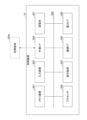
- Fig. 3 is a diagram showing an example of a hardware configuration of the control device 10 according to the present embodiment.
- the control device 10 has a storage battery 201, an input device 202, a display device 203, an external I/F 204, a communication I/F 205, a power I/F 206, a memory device 207, and a processor 208.
- a storage battery 201 an input device 202, a display device 203, an external I/F 204, a communication I/F 205, a power I/F 206, a memory device 207, and a processor 208.
- Each of these pieces of hardware are connected to each other via a bus 209 so that they can communicate with each other.
- the storage battery 201 is a battery capable of storing power. As described above, the storage battery 201 includes a power storage unit 211, N input measurement units 212, an output measurement unit 213, and a remaining capacity measurement unit 214. However, each of the input measurement units 212, output measurement units 213, and remaining capacity measurement units 214 does not necessarily have to be included in the storage battery 201, and may exist outside the storage battery 201.
- the input device 202 is, for example, a keyboard, a mouse, a touch panel, various operation buttons, etc.
- the display device 203 is, for example, a display, etc. Note that the control device 10 does not necessarily have to have at least one of the input device 202 and the display device 203.
- the external I/F 204 is an interface with external devices such as a recording medium 204a.
- Examples of the recording medium 204a include a CD, a DVD, an SD memory card, and a USB memory.
- the communication I/F 205 is an interface for connecting the control device 10 to a communication network.
- the power I/F 206 is an interface for connecting the control device 10 to a power transmission and distribution network.
- the memory device 207 is, for example, a variety of storage devices such as a RAM (Random Access Memory), a ROM (Read Only Memory), a flash memory, a HDD (Hard Disk Drive), or an SSD (Solid State Drive).
- the memory unit 104 can be realized, for example, using the memory device 207. However, the memory unit 104 may also be realized, for example, by a storage device or a database server connected to the control device 10 via a communication network.
- the processor 208 is, for example, a variety of arithmetic devices such as a CPU (Central Processing Unit). Each functional unit of the control device 10 (for example, the communication unit 101, the battery control unit 102, and the remaining capacity management unit 103) is realized, for example, by processing that one or more programs stored in the memory device 207 are executed by the processor 208.
- a CPU Central Processing Unit
- the control device 10 has the hardware configuration shown in FIG. 3, and is therefore capable of implementing the remaining amount management process described below.
- the hardware configuration shown in FIG. 3 is merely an example, and the control device 10 may have other hardware configurations.
- the control device 10 according to this embodiment may have multiple memory devices 207, or multiple processors 208.
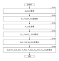
- the remaining capacity management unit 103 acquires the remaining capacity SoC(t) of the power storage unit 211 from the remaining capacity measurement unit 214 (step S101).
- the remaining amount management unit 103 acquires the cumulative value P in _F(t) of the amount of power input from the power source originating from the “grid” during the past ⁇ t, and the cumulative value P in _G(t) of the amount of power input from the power source originating from the “renewable energy” during the past ⁇ t from the input measurement unit 212-1 and the input measurement unit 212-2, respectively (step S102).
- the remaining amount management unit 103 acquires an accumulated value P out (t) of the amount of power output to the power transmission and distribution network during the past ⁇ t (step S103).
- step S105 the remaining capacity management unit 103 calculates SoC_F(t) and SoC_G(t) according to steps 1 and 2 below.
- Step 1 First, the remaining capacity management unit 103 calculates SoC'_F(t) and SoC'_G(t) as follows:
- SoC'_F(t) SoC_F(t-1)+P in _F(t)-P out _F(t)
- SoC'_G(t) SoC_G(t-1)+P in _G(t)-P out _G(t)
- SoC_F(t) SoC(t) ⁇ SoC'_F(t)/(SoC'_F(t)+SoC'_G(t))
- SoC_G(t) SoC(t) ⁇ SoC'_G(t)/(SoC'_F(t)+SoC'_G(t))
- remaining capacity management unit 103 stores SoC_F(t), SoC_G(t), Pin_F (t), Pin_G (t), P out_F (t), and P out_G (t) in storage unit 104 (step S106).
- the control device 10 can manage the amount of stored power (remaining amount) of the storage battery 201 for each power source when the amount of power from a plurality of power sources is stored in the storage battery 201. Moreover, at this time, the control device 10 according to the present embodiment can calculate the remaining amount taking into consideration, for example, natural discharge and charge/discharge loss by using a measurement value obtained by measuring the remaining amount of the storage battery 201, and can obtain a remaining amount with higher accuracy than the conventional technology.
- the above embodiment can be easily extended to cases where N ⁇ 3 or more, and the amount of stored power (remaining power) of each power source of the storage battery 201 can be calculated and managed in a similar manner.
- the control device 10 has both the functions of controlling the power supply from the storage battery and managing the remaining capacity of each power source, but for example, the power supply control function and the remaining capacity management function may be provided in separate devices.
- the device with the power supply control function may be called the "control device” and the device with the remaining capacity management function may be called the "management device”.
- Control device 20 Server 101 Communication unit 102 Storage battery control unit 103 Remaining capacity management unit 104 Memory unit 201 Storage battery 202 Input device 203 Display device 204 External I/F 204a Recording medium 205 Communication I/F 206 Power I/F 207 Memory device 208 Processor 209 Bus 211 Power storage unit 212 Input measurement unit 213 Output measurement unit 214 Remaining amount measurement unit
Landscapes
- Engineering & Computer Science (AREA)
- Manufacturing & Machinery (AREA)
- Chemical & Material Sciences (AREA)
- Chemical Kinetics & Catalysis (AREA)
- Electrochemistry (AREA)
- General Chemical & Material Sciences (AREA)
- Power Engineering (AREA)
- Charge And Discharge Circuits For Batteries Or The Like (AREA)
- Supply And Distribution Of Alternating Current (AREA)
Abstract
本開示の一態様による管理装置は、各時刻における蓄電池の残量を電源毎に管理する管理装置であって、現在時刻において、前記蓄電池の残量を計測した第1の計測値と、前記蓄電池への充電量を前記電源毎に計測した第2の計測値と、前記蓄電池からの放電量を計測した第3の計測値とを取得する取得部と、前記第3の計測値に基づいて、前記蓄電池からの放電量のうち、前記電源毎の放電量を算出する第1の算出部と、前記第1の計測値と、前記電源毎の前記第2の計測値と、1時刻前の前記蓄電池における前記電源毎の残量と、前記電源毎の放電量とに基づいて、前記電源毎に、1時刻前の前記蓄電池における前記電源の残量と前記電源の前記第2の計測値との和から前記電源の放電量を減算した値を、前記第1の計測値が前記蓄電池における電源毎の残量の和に等しいことを表す関係を利用して補正することで前記電源の残量を算出する第2の算出部と、を有する。
Description
本開示は、管理装置、管理方法及びプログラムに関する。
近年、様々な電源からの電力を統合及び制御して、あたかも1つの発電所のように機能させるバーチャルパワープラント(VPP:Virtual Power Plant)と呼ばれる仕組みが知られている。バーチャルパワープラントは、例えば、太陽光発電や風力発電、水力発電、火力発電、原子力発電等の様々な電源からの電力を統合及び制御し、これらの電源からの電力を蓄電池に蓄えておくことが可能である。
一方で、環境負荷低減に対する意識の高まりから、例えば、電力供給をバーチャルパワープラントに要求する際に、その電力の電源(系統/再生可能エネルギー)を明確にしたいというニーズがある。これに対して、蓄電池に蓄電されている電力とその蓄電池から放電される電力の電源を明確化できる従来技術が存在する(例えば、非特許文献1等)。
しかしながら、従来技術では、蓄電池の入出力電力を計測することにより電力の電源を明確化しており、蓄電池の残量そのものは計測していない。このため、例えば、蓄電池の自然放電や充放電損失が考慮されておらず、時間経過に伴って真の残量との間に乖離が生じる可能性がある。
本開示は、上記の点に鑑みてなされたもので、電源毎の残量を精度良く管理できる技術を提供する。
本開示の一態様による管理装置は、各時刻における蓄電池の残量を電源毎に管理する管理装置であって、現在時刻において、前記蓄電池の残量を計測した第1の計測値と、前記蓄電池への充電量を前記電源毎に計測した第2の計測値と、前記蓄電池からの放電量を計測した第3の計測値とを取得する取得部と、前記第3の計測値に基づいて、前記蓄電池からの放電量のうち、前記電源毎の放電量を算出する第1の算出部と、前記第1の計測値と、前記電源毎の前記第2の計測値と、1時刻前の前記蓄電池における前記電源毎の残量と、前記電源毎の放電量とに基づいて、前記電源毎に、1時刻前の前記蓄電池における前記電源の残量と前記電源の前記第2の計測値との和から前記電源の放電量を減算した値を、前記第1の計測値が前記蓄電池における電源毎の残量の和に等しいことを表す関係を利用して補正することで前記電源の残量を算出する第2の算出部と、を有する。
電源毎の残量を精度良く管理できる技術が提供される。
以下、本発明の一実施形態について説明する。以下の実施形態では、複数の電源からの電力が蓄電される蓄電池を備えるバーチャルパワープラントにおいて、その供給を制御すると共に、電源毎の残量を精度良く管理することが可能な制御装置10について説明する。
<制御装置10の全体構成例>
まず、本実施形態に係る制御装置10の全体構成例について、図1を参照しながら説明する。図1は、本実施形態に係る制御装置10の全体構成の一例を示す図である。
まず、本実施形態に係る制御装置10の全体構成例について、図1を参照しながら説明する。図1は、本実施形態に係る制御装置10の全体構成の一例を示す図である。
図1に示すように、本実施形態に係る制御装置10は、複数の電源と接続され、これら複数の電源からの電力を蓄電する蓄電池201を有するコンピュータ又はコンピュータシステムである。以下、電源の数をN(ただし、Nは2以上の整数)として、「電源1」、・・・、「電源N」とする。電源には、例えば、太陽光発電、風力発電、水力発電、火力発電、原子力発電等の様々な種類がある。以下では、主に、N=2である場合を想定し、電源1は系統由来の電源、電源2は再生可能エネルギー(以下、略して「再エネ」ともいう。)由来の電源であるものとする。なお、系統由来の電源としては、例えば、火力発電、原子力発電等が挙げられる。一方で、再エネ由来の電源としては、例えば、太陽光発電、風力発電、水力発電等が挙げられる。
また、本実施形態に係る制御装置10は、必要な電力を要求するためのリクエストをサーバ20から受信したことに応じて、蓄電池201に蓄電されている電力を供給する。一例として、このリクエストには、必要な電力の量(要求電力量)と、その要求電力量のうち「再エネ」由来の電力量の割合又は比率(以下、「再エネ比率」とする。)とが指定されている。具体的には、例えば、要求電力量「a〔kW〕」、再エネ比率「0.5」等がリクエストに指定されている。これは、要求電力量a〔kW〕のうち、その半分を「再エネ」由来の電力量、残りを「系統」由来の電力量を要求することを意味する。ただし、これは一例であって、リクエストには、例えば、再エネ比率の代わりに、要求電力量に対する各電源由来の電力量の比率(割合)が指定されていてもよい。また、例えば、リクエストには、要求電力量が必要な時期(要求時期)が指定されていてもよい。
なお、上記のリクエストは、例えば、電力会社や電力市場等からのデマンドレスポンスに相当する。
ここで、本実施形態に係る制御装置10は、通信部101と、蓄電池制御部102と、残量管理部103と、記憶部104とを有する。
通信部101は、通信ネットワーク(例えば、LAN(Local Area Network)、携帯電話網、インターネット等)を介して、リクエストをサーバ20から受信する。
蓄電池制御部102は、通信部101によりリクエストが受信された場合、蓄電池201を制御して、当該リクエストに指定されている要求電力量を出力(放電)する。
残量管理部103は、電源の由来(つまり、「系統」、「再エネ」)毎にその電源による蓄電量(残量)等を計算して記憶部104に保存する。
記憶部104は、電源の由来毎の蓄電量(残量)を示す情報やそれ以外の種々の情報等を記憶する。
≪蓄電池201の構成例≫
ここで、本実施形態に係る蓄電池201の構成例について、図2を参照しながら説明する。図2は、本実施形態に係る蓄電池201の構成の一例を示す図である。
ここで、本実施形態に係る蓄電池201の構成例について、図2を参照しながら説明する。図2は、本実施形態に係る蓄電池201の構成の一例を示す図である。
図2に示すように、本実施形態に係る蓄電池201は、蓄電部211と、N個の入力計測部212と、出力計測部213と、残量計測部214とを有する。
蓄電部211は、電源1~電源Nの各々から入力された電力を蓄電する。また、蓄電部211は、蓄電池制御部102の制御に従って送配電網に放電する。
入力計測部212は、積分計等の電力計により実現され、予め決められた時間幅Δt毎に、その時間幅Δtの間に当該入力計測部212に対応する電源から入力された電力の電力量(つまり、充電量)の累積値を計測してその計測値を保持する。図2に示す例では、n=1,・・・,Nとして、電源nから入力された電力の電力量の時間幅Δt毎の累積値を計測する入力計測部212を「入力計測部212n」で表している。なお、Δtは、例えば、30分等とすることが考えられるが、これに限定されるものではない。
以下、t←t+Δtと更新される時刻をtとして、時刻tで入力計測部2121により計測された計測値(つまり、時間幅Δtの間に「系統」由来の電源から入力された電力量の累積値)をPin_F(t)とする。同様に、時刻tで入力計測部2122により計測された計測値(つまり、時間幅Δtの間に「再エネ」由来の電源から入力された電力量の累積値)をPin_G(t)とする。
出力計測部213は、積分計等の電力計により実現され、予め決められた時間幅Δt毎に、その時間幅Δtの間に送配電網に出力された電力量(つまり、放電量)の累積値を計測してその計測値を保持する。以下、時刻tで出力計測部213により計測された計測値(つまり、時間幅Δtの間の放電量の累積値)をPout(t)とする。ここで、Pout(t)のうち、「系統」由来の放電量をPout_F(t)、「再エネ」由来の放電量をPout_G(t)、リクエストに指定されている再エネ比率をαとすれば、Pout_G(t)=α×Pout(t)、Pout_F(t)=Pout(t)-Pout_G(t)と表される。
残量計測部214は、予め決められた時間幅Δt毎に、蓄電部211の残量(蓄電量の残量)を計測してその計測値を保持する。以下、時刻tで残量計測部214により計測された計測値(つまり、時刻tにおける蓄電部211の残量)をSoC(t)とする。
このとき、SoC(t)のうち、「系統」由来の残量をSoC_F(t)、「再エネ」由来の残量をSoC_G(t)としたとき、これらのSoC_F(t)及びSoC_G(t)を求めて記憶部104に保存することが目的である。仮に自然放電や充放電損失が無いと仮定した場合、ΔSoC=SoC(t)-SoC(t-1)、ΔP=Pin_F(t)+Pin_G(t)-Pout(t)としたときΔSoC=ΔPが成り立つため、以下によりSoC_F(t)及びSoC_G(t)を求めることができる。
SoC_F(t)=SoC_F(t-1)+Pin_F(t)-Pout_F(t)
SoC_G(t)=SoC_G(t-1)+Pin_G(t)-Pout_G(t)
しかしながら、一般に蓄電池201には自然放電や充放電損失が発生し得るため、厳密には上記によりSoC_F(t)及びSoC_G(t)を求めることはできない。そこで、本実施形態に係る制御装置10では、上記のSoC_F(t)及びSoC_G(t)を補正することにより精度の良い残量を求める。
SoC_G(t)=SoC_G(t-1)+Pin_G(t)-Pout_G(t)
しかしながら、一般に蓄電池201には自然放電や充放電損失が発生し得るため、厳密には上記によりSoC_F(t)及びSoC_G(t)を求めることはできない。そこで、本実施形態に係る制御装置10では、上記のSoC_F(t)及びSoC_G(t)を補正することにより精度の良い残量を求める。
<制御装置10のハードウェア構成例>
次に、本実施形態に係る制御装置10のハードウェア構成例について、図3を参照しながら説明する。図3は、本実施形態に係る制御装置10のハードウェア構成の一例を示す図である。
次に、本実施形態に係る制御装置10のハードウェア構成例について、図3を参照しながら説明する。図3は、本実施形態に係る制御装置10のハードウェア構成の一例を示す図である。
図3に示すように、本実施形態に係る制御装置10は、蓄電池201と、入力装置202と、表示装置203と、外部I/F204と、通信I/F205と、電力I/F206と、メモリ装置207と、プロセッサ208とを有する。これら各ハードウェアは、バス209により相互に通信可能に接続されている。
蓄電池201は、電力を蓄えることが可能な電池である。なお、上述したように、蓄電池201には、蓄電部211と、N個の入力計測部212と、出力計測部213と、残量計測部214とが含まれる。ただし、各入力計測部212と出力計測部213と残量計測部214は、必ずしも蓄電池201に含まれている必要はなく、蓄電池201の外部に存在してもよい。
入力装置202は、例えば、キーボードやマウス、タッチパネル、各種操作ボタン等である。表示装置203は、例えば、ディスプレイ等である。なお、制御装置10は、入力装置202及び表示装置203のうちの少なくとも一方を有していなくてもよい。
外部I/F204は、記録媒体204a等の外部装置とのインタフェースである。記録媒体204aとしては、例えば、CD、DVD、SDメモリカード、USBメモリ等が挙げられる。
通信I/F205は、制御装置10を通信ネットワークに接続するためのインタフェースである。電力I/F206は、制御装置10を送配電網に接続するためのインタフェースである。
メモリ装置207は、例えば、RAM(Random Access Memory)やROM(Read Only Memory)、フラッシュメモリ、HDD(Hard Disk Drive)、SSD(Solid State Drive)等の各種記憶装置である。記憶部104は、例えば、メモリ装置207を用いて実現可能である。ただし、記憶部104は、例えば、制御装置10と通信ネットワークを介して接続される記憶装置やデータベースサーバ等により実現されていてもよい。
プロセッサ208は、例えば、CPU(Central Processing Unit)等の各種演算装置である。制御装置10が有する各機能部(例えば、通信部101、蓄電池制御部102及び残量管理部103等)は、例えば、メモリ装置207に格納された1以上のプログラムがプロセッサ208に実行させる処理により実現される。
本実施形態に係る制御装置10は、図3に示すハードウェア構成を有することにより、後述する残量管理処理を実現することができる。なお、図3に示すハードウェア構成は一例であって、制御装置10は、他のハードウェア構成を有していてもよい。例えば、本実施形態に係る制御装置10は、複数のメモリ装置207を有していてもよいし、複数のプロセッサ208を有していてもよい。
<残量管理処理>
以下、本実施形態に係る残量管理処理の一例ついて、図4を参照しながら説明する。以下では、或る時刻tにおけるSoC_F(t)及びSoC_G(t)を求める場合について説明する。なお、以下では、その1つ前の時刻t-1におけるSoC_F(t-1)、SoC_G(t-1)、Pin_F(t-1)、Pin_G(t-1)、Pout_F(t-1)、Pout_G(t-1)は既知であり、記憶部104に保存されているものとする。
以下、本実施形態に係る残量管理処理の一例ついて、図4を参照しながら説明する。以下では、或る時刻tにおけるSoC_F(t)及びSoC_G(t)を求める場合について説明する。なお、以下では、その1つ前の時刻t-1におけるSoC_F(t-1)、SoC_G(t-1)、Pin_F(t-1)、Pin_G(t-1)、Pout_F(t-1)、Pout_G(t-1)は既知であり、記憶部104に保存されているものとする。
まず、残量管理部103は、蓄電部211の残量SoC(t)を残量計測部214から取得する(ステップS101)。
次に、残量管理部103は、過去Δtの間に「系統」由来の電源から入力された電力量の累積値Pin_F(t)と、過去Δtの間に「再エネ」由来の電源から入力された電力量の累積値Pin_G(t)とを入力計測部2121と入力計測部2122からそれぞれ取得する(ステップS102)。
次に、残量管理部103は、過去Δtの間に送配電網に出力された電力量の累積値Pout(t)を取得する(ステップS103)。
次に、残量管理部103は、上記のステップS103で取得したPout(t)と、このPout(t)の放電が行われたときのリクエストに指定されている再エネ比率αとを用いて、Pout_G(t)=α×Pout(t)、Pout_F(t)=Pout(t)-Pout_G(t)によりPout_G(t)とPout_F(t)を算出する(ステップS104)。これにより、時刻tにおける放電量に関して、電源毎の放電量を得ることができる。
次に、残量管理部103は、以下の手順1~手順2によりSoC_F(t)及びSoC_G(t)を算出する(ステップS105)。
手順1:まず、残量管理部103は、以下によりSoC'_F(t)及びSoC'_G(t)を算出する。
SoC'_F(t)=SoC_F(t-1)+Pin_F(t)-Pout_F(t)
SoC'_G(t)=SoC_G(t-1)+Pin_G(t)-Pout_G(t)
手順2:各電源由来の残量の和が全体の残量になるため、SoC(t)=SoC_F(t)+SoC_G(t)を満たす必要がある。そこで、残量管理部103は、この関係を満たすように上記のSoC'_F(t)及びSoC'_G(t)を以下により補正してSoC_F(t)及びSoC_G(t)を算出する。
SoC'_G(t)=SoC_G(t-1)+Pin_G(t)-Pout_G(t)
手順2:各電源由来の残量の和が全体の残量になるため、SoC(t)=SoC_F(t)+SoC_G(t)を満たす必要がある。そこで、残量管理部103は、この関係を満たすように上記のSoC'_F(t)及びSoC'_G(t)を以下により補正してSoC_F(t)及びSoC_G(t)を算出する。
SoC_F(t)=SoC(t)×SoC'_F(t)/(SoC'_F(t)+SoC'_G(t))
SoC_G(t)=SoC(t)×SoC'_G(t)/(SoC'_F(t)+SoC'_G(t))
これにより、SoC(t)=SoC_F(t)+SoC_G(t)を満たすSoC_F(t)及びSoC_G(t)が得られる。
SoC_G(t)=SoC(t)×SoC'_G(t)/(SoC'_F(t)+SoC'_G(t))
これにより、SoC(t)=SoC_F(t)+SoC_G(t)を満たすSoC_F(t)及びSoC_G(t)が得られる。
そして、残量管理部103は、SoC_F(t)、SoC_G(t)、Pin_F(t)、Pin_G(t)、Pout_F(t)、Pout_G(t)を記憶部104に保存する(ステップS106)。
以上のステップS101~ステップS106が各時刻tで実行されることにより、各時刻tで電源の由来毎の蓄電池201の残量SoC_F(t)及びSoC_G(t)が得られる。
<まとめ>
以上のように、本実施形態に係る制御装置10は、複数の電源からの電力量を蓄電池201に蓄電している場合において、その蓄電池201の蓄電量(残量)を電源毎に管理することができる。しかも、このとき、本実施形態に係る制御装置10は、蓄電池201の残量を計測した計測値を用いることにより、例えば自然放電や充放電損失等も考慮した残量を算出ことが可能となり、従来技術と比較して精度の良い残量を得ることができる。
以上のように、本実施形態に係る制御装置10は、複数の電源からの電力量を蓄電池201に蓄電している場合において、その蓄電池201の蓄電量(残量)を電源毎に管理することができる。しかも、このとき、本実施形態に係る制御装置10は、蓄電池201の残量を計測した計測値を用いることにより、例えば自然放電や充放電損失等も考慮した残量を算出ことが可能となり、従来技術と比較して精度の良い残量を得ることができる。
なお、上記の実施形態では、一例として、主に、N=2である場合を想定して説明したが、これは一例であることは言うまでもない。N≧3以上である場合も上記の実施形態は容易に拡張することが可能であり、蓄電池201の電源毎の蓄電量(残量)を同様に算出及び管理することが可能である。
また、上記の実施形態に係る制御装置10は、蓄電池からの電力供給制御と電源毎の残量管理の両方の機能を備えているが、例えば、電力供給制御機能と残量管理機能とを別々の装置が備えていてもよい。この場合、例えば、電力供給制御機能を備える装置を「制御装置」、残量管理機能を備える装置を「管理装置」等と呼んでもよい。
本発明は、具体的に開示された上記の実施形態に限定されるものではなく、請求の範囲の記載から逸脱することなく、種々の変形や変更等が可能である。
10 制御装置
20 サーバ
101 通信部
102 蓄電池制御部
103 残量管理部
104 記憶部
201 蓄電池
202 入力装置
203 表示装置
204 外部I/F
204a 記録媒体
205 通信I/F
206 電力I/F
207 メモリ装置
208 プロセッサ
209 バス
211 蓄電部
212 入力計測部
213 出力計測部
214 残量計測部
20 サーバ
101 通信部
102 蓄電池制御部
103 残量管理部
104 記憶部
201 蓄電池
202 入力装置
203 表示装置
204 外部I/F
204a 記録媒体
205 通信I/F
206 電力I/F
207 メモリ装置
208 プロセッサ
209 バス
211 蓄電部
212 入力計測部
213 出力計測部
214 残量計測部
Claims (6)
- 各時刻における蓄電池の残量を電源毎に管理する管理装置であって、
現在時刻において、前記蓄電池の残量を計測した第1の計測値と、前記蓄電池への充電量を前記電源毎に計測した第2の計測値と、前記蓄電池からの放電量を計測した第3の計測値とを取得する取得部と、
前記第3の計測値に基づいて、前記蓄電池からの放電量のうち、前記電源毎の放電量を算出する第1の算出部と、
前記第1の計測値と、前記電源毎の前記第2の計測値と、1時刻前の前記蓄電池における前記電源毎の残量と、前記電源毎の放電量とに基づいて、前記電源毎に、1時刻前の前記蓄電池における前記電源の残量と前記電源の前記第2の計測値との和から前記電源の放電量を減算した値を、前記第1の計測値が前記蓄電池における電源毎の残量の和に等しいことを表す関係を利用して補正することで前記電源の残量を算出する第2の算出部と、
を有する管理装置。 - 前記電源は、系統と再生可能エネルギーであり、
前記第1の算出部は、
現在時刻tにおける前記再生可能エネルギーの放電量をPout_G(t)、前記系統の放電量をPout_F(t)、前記第3の計測値をPout(t)としたとき、前記蓄電池から前記放電量を放電させるためリクエストに含まれる再生可能エネルギー比率αを用いて、前記再生可能エネルギーの放電量をPout_G(t)=α×Pout(t)、前記系統の放電量をPout_F(t)=Pout(t)-Pout_G(t)により算出する、請求項1に記載の管理装置。 - 前記第2の算出部は、
前記第1の計測値をSoC(t)、前記系統の前記第2の計測値をPin_F(t)、前記再生可能エネルギーの前記第2の計測値をPin_G(t)、1時刻前の前記蓄電池における前記系統由来の電力の残量をSoC_F(t-1)、1時刻前の前記蓄電池における前記再生可能エネルギー由来の電力の残量をSoC_G(t-1)としたとき、
SoC'_F(t)=SoC_F(t-1)+Pin_F(t)-Pout_F(t)
SoC'_G(t)=SoC_G(t-1)+Pin_G(t)-Pout_G(t)
を算出し、SoC(t)=SoC_F(t)+SoC_G(t)との関係を利用してSoC'_F(t)及びSoC'_G(t)をそれぞれ補正することで、現在時刻tにおける前記蓄電池の系統由来の電力の残量と、現在時刻tにおける前記蓄電池の再生可能エネルギー由来の電力の残量とをそれぞれ算出する、請求項2に記載の管理装置。 - 前記第2の算出部は、
現在時刻tにおける前記蓄電池の系統由来の電力の残量をSoC_F(t)、現在時刻tにおける前記蓄電池の再生可能エネルギー由来の電力の残量をSoC_G(t)としたとき、
SoC_F(t)=SoC(t)×SoC'_F(t)/(SoC'_F(t)+SoC'_G(t))
SoC_G(t)=SoC(t)×SoC'_G(t)/(SoC'_F(t)+SoC'_G(t))
により前記SoC_F(t)と前記SoC_G(t)とをそれぞれ算出する、請求項3に記載の管理装置。 - 各時刻における蓄電池の残量を電源毎に管理する管理装置が、
現在時刻において、前記蓄電池の残量を計測した第1の計測値と、前記蓄電池への充電量を前記電源毎に計測した第2の計測値と、前記蓄電池からの放電量を計測した第3の計測値とを取得する取得手順と、
前記第3の計測値に基づいて、前記蓄電池からの放電量のうち、前記電源毎の放電量を算出する第1の算出手順と、
前記第1の計測値と、前記電源毎の前記第2の計測値と、1時刻前の前記蓄電池における前記電源毎の残量と、前記電源毎の放電量とに基づいて、前記電源毎に、1時刻前の前記蓄電池における前記電源の残量と前記電源の前記第2の計測値との和から前記電源の放電量を減算した値を、前記第1の計測値が前記蓄電池における電源毎の残量の和に等しいことを表す関係を利用して補正することで前記電源の残量を算出する第2の算出手順と、
を実行する管理方法。 - 各時刻における蓄電池の残量を電源毎に管理する管理装置に、
現在時刻において、前記蓄電池の残量を計測した第1の計測値と、前記蓄電池への充電量を前記電源毎に計測した第2の計測値と、前記蓄電池からの放電量を計測した第3の計測値とを取得する取得手順と、
前記第3の計測値に基づいて、前記蓄電池からの放電量のうち、前記電源毎の放電量を算出する第1の算出手順と、
前記第1の計測値と、前記電源毎の前記第2の計測値と、1時刻前の前記蓄電池における前記電源毎の残量と、前記電源毎の放電量とに基づいて、前記電源毎に、1時刻前の前記蓄電池における前記電源の残量と前記電源の前記第2の計測値との和から前記電源の放電量を減算した値を、前記第1の計測値が前記蓄電池における電源毎の残量の和に等しいことを表す関係を利用して補正することで前記電源の残量を算出する第2の算出手順と、
を実行させるプログラム。
Priority Applications (2)
| Application Number | Priority Date | Filing Date | Title |
|---|---|---|---|
| PCT/JP2023/021239 WO2024252591A1 (ja) | 2023-06-07 | 2023-06-07 | 管理装置、管理方法及びプログラム |
| JP2025525554A JPWO2024252591A1 (ja) | 2023-06-07 | 2023-06-07 |
Applications Claiming Priority (1)
| Application Number | Priority Date | Filing Date | Title |
|---|---|---|---|
| PCT/JP2023/021239 WO2024252591A1 (ja) | 2023-06-07 | 2023-06-07 | 管理装置、管理方法及びプログラム |
Publications (1)
| Publication Number | Publication Date |
|---|---|
| WO2024252591A1 true WO2024252591A1 (ja) | 2024-12-12 |
Family
ID=93795613
Family Applications (1)
| Application Number | Title | Priority Date | Filing Date |
|---|---|---|---|
| PCT/JP2023/021239 Ceased WO2024252591A1 (ja) | 2023-06-07 | 2023-06-07 | 管理装置、管理方法及びプログラム |
Country Status (2)
| Country | Link |
|---|---|
| JP (1) | JPWO2024252591A1 (ja) |
| WO (1) | WO2024252591A1 (ja) |
Citations (3)
| Publication number | Priority date | Publication date | Assignee | Title |
|---|---|---|---|---|
| JPS59137581U (ja) * | 1983-03-03 | 1984-09-13 | 松下電工株式会社 | 電池残量表示回路 |
| WO2021084659A1 (ja) * | 2019-10-30 | 2021-05-06 | 日本電信電話株式会社 | 制御装置、制御方法及びプログラム |
| JP2023042959A (ja) * | 2021-09-15 | 2023-03-28 | オムロン株式会社 | 電池容量推定装置、充電計画生成装置、放電計画生成装置及び電池容量推定方法 |
-
2023
- 2023-06-07 JP JP2025525554A patent/JPWO2024252591A1/ja active Pending
- 2023-06-07 WO PCT/JP2023/021239 patent/WO2024252591A1/ja not_active Ceased
Patent Citations (3)
| Publication number | Priority date | Publication date | Assignee | Title |
|---|---|---|---|---|
| JPS59137581U (ja) * | 1983-03-03 | 1984-09-13 | 松下電工株式会社 | 電池残量表示回路 |
| WO2021084659A1 (ja) * | 2019-10-30 | 2021-05-06 | 日本電信電話株式会社 | 制御装置、制御方法及びプログラム |
| JP2023042959A (ja) * | 2021-09-15 | 2023-03-28 | オムロン株式会社 | 電池容量推定装置、充電計画生成装置、放電計画生成装置及び電池容量推定方法 |
Also Published As
| Publication number | Publication date |
|---|---|
| JPWO2024252591A1 (ja) | 2024-12-12 |
Similar Documents
| Publication | Publication Date | Title |
|---|---|---|
| JP2016135040A (ja) | 電力需給調整要請量決定装置及びその方法 | |
| CN110235329A (zh) | 量化电力网中相互依赖的不确定资源的组合效应 | |
| CN110674452A (zh) | 发电机组年度基础电量的分解方法和装置 | |
| CN111082424B (zh) | 一种综合能源及微电网系统可靠性预测方法及装置 | |
| WO2017154116A1 (ja) | 電力制御装置、電力制御システム、電力制御方法、及び、プログラム | |
| JP2022007988A (ja) | 電力管理装置、電力管理システム、電力管理方法 | |
| CN102027709A (zh) | 用于面向服务和效用基础结构使用测量、计量和定价的基于字节的方法、过程和算法 | |
| CN115618654A (zh) | 超差电能表的识别方法及装置 | |
| TWI652591B (zh) | Operation plan preparation device, operation plan formulation method and memory medium | |
| Chen et al. | Pricing real-time stochastic storage operations | |
| WO2024252591A1 (ja) | 管理装置、管理方法及びプログラム | |
| JP7226581B2 (ja) | 制御装置、制御方法及びプログラム | |
| CN108877969A (zh) | 核功率理论模型建立及验证方法、系统及终端设备 | |
| KR20220102813A (ko) | 에너지저장장치 최적용량 산정 장치 및 방법 | |
| JP2025017255A (ja) | 充放電時間決定装置、充放電時間決定方法、及びプログラム | |
| JP7767938B2 (ja) | 情報処理装置、情報処理方法及び情報処理プログラム | |
| CN113689033B (zh) | 容量发电价核定方法、装置、计算机设备和存储介质 | |
| JP2025021637A (ja) | 充放電計画作成装置、充放電計画作成方法、及びプログラム | |
| WO2019207935A1 (ja) | 電力系統制御システム、及び、電力系統制御方法 | |
| KR102905988B1 (ko) | 양수 발전 비용 검증 장치 및 방법 | |
| CN119006216B (zh) | 新能源电网线损量化方法及装置 | |
| JP7235181B1 (ja) | 情報処理装置、発電システム、及び情報処理方法 | |
| JP7215648B1 (ja) | 情報処理装置、発電システム、及び情報処理方法 | |
| CN111489189A (zh) | 一种电力现货市场电价的概率预测方法、装置及存储介质 | |
| CN110659824A (zh) | 电量平衡测算方法和装置 |
Legal Events
| Date | Code | Title | Description |
|---|---|---|---|
| 121 | Ep: the epo has been informed by wipo that ep was designated in this application |
Ref document number: 23940692 Country of ref document: EP Kind code of ref document: A1 |
|
| ENP | Entry into the national phase |
Ref document number: 2025525554 Country of ref document: JP Kind code of ref document: A |
|
| NENP | Non-entry into the national phase |
Ref country code: DE |