WO2024252554A1 - 逆浸透膜浄水器 - Google Patents
逆浸透膜浄水器 Download PDFInfo
- Publication number
- WO2024252554A1 WO2024252554A1 PCT/JP2023/021146 JP2023021146W WO2024252554A1 WO 2024252554 A1 WO2024252554 A1 WO 2024252554A1 JP 2023021146 W JP2023021146 W JP 2023021146W WO 2024252554 A1 WO2024252554 A1 WO 2024252554A1
- Authority
- WO
- WIPO (PCT)
- Prior art keywords
- water
- reverse osmosis
- osmosis membrane
- permeated
- unit
- Prior art date
- Legal status (The legal status is an assumption and is not a legal conclusion. Google has not performed a legal analysis and makes no representation as to the accuracy of the status listed.)
- Ceased
Links
Images



Classifications
-
- B—PERFORMING OPERATIONS; TRANSPORTING
- B01—PHYSICAL OR CHEMICAL PROCESSES OR APPARATUS IN GENERAL
- B01D—SEPARATION
- B01D61/00—Processes of separation using semi-permeable membranes, e.g. dialysis, osmosis or ultrafiltration; Apparatus, accessories or auxiliary operations specially adapted therefor
- B01D61/02—Reverse osmosis; Hyperfiltration ; Nanofiltration
- B01D61/12—Controlling or regulating
-
- B—PERFORMING OPERATIONS; TRANSPORTING
- B01—PHYSICAL OR CHEMICAL PROCESSES OR APPARATUS IN GENERAL
- B01D—SEPARATION
- B01D61/00—Processes of separation using semi-permeable membranes, e.g. dialysis, osmosis or ultrafiltration; Apparatus, accessories or auxiliary operations specially adapted therefor
- B01D61/58—Multistep processes
-
- C—CHEMISTRY; METALLURGY
- C02—TREATMENT OF WATER, WASTE WATER, SEWAGE, OR SLUDGE
- C02F—TREATMENT OF WATER, WASTE WATER, SEWAGE, OR SLUDGE
- C02F1/00—Treatment of water, waste water, or sewage
- C02F1/44—Treatment of water, waste water, or sewage by dialysis, osmosis or reverse osmosis
Definitions
- This disclosure relates to a reverse osmosis water purifier.
- Patent Document 1 discloses a filtration treatment device that uses a reverse osmosis membrane module.
- the reverse osmosis membrane module separates the water to be treated into filtered water and concentrated water.
- Multiple reverse osmosis membrane modules are provided.
- the multiple reverse osmosis membrane modules are connected in series by a line for the water to be treated and a line for the concentrated water.
- the problem to be solved by this disclosure is to provide a reverse osmosis water purifier that can easily produce more purified water.
- the first reverse osmosis membrane water purifier comprises a number of reverse osmosis membrane modules that process introduced water to pass it through a reverse osmosis membrane and separate it into permeated water that has passed through the reverse osmosis membrane and non-permeated water that has not passed through the reverse osmosis membrane and discharge the separated water; a flow rate measuring unit that measures the flow rate of the permeated water; a water flow unit that forms a parallel flow path in which a number of the reverse osmosis membrane modules are connected in parallel, and a serial flow path in which a number of the reverse osmosis membrane modules are connected in series on the non-permeated water side; and a switching unit that freely switches the water flow state between a state in which water can pass through the parallel flow paths and a state in which water can pass through the serial flow paths.
- the second reverse osmosis membrane water purifier includes a plurality of reverse osmosis membrane modules that process introduced water to pass it through a reverse osmosis membrane and separate it into permeated water that has passed through the reverse osmosis membrane and non-permeated water that has not passed through the reverse osmosis membrane and discharges it; a concentration measuring unit that measures the TDS concentration of the non-permeated water; a water flow unit that forms a parallel flow path in which a plurality of the reverse osmosis membrane modules are connected in parallel and a serial flow path in which a plurality of the reverse osmosis membrane modules are connected in series on the non-permeated water side; and a switching unit that freely switches the water flow state between a state in which water can pass through the parallel flow path and a state in which water can pass through the serial flow path.
- the third reverse osmosis membrane water purifier comprises a number of reverse osmosis membrane modules that process introduced water to pass it through a reverse osmosis membrane and separate it into permeated water that has passed through the reverse osmosis membrane and non-permeated water that has not passed through the reverse osmosis membrane and discharge it; a concentration measuring unit that measures the TDS concentration of the water; a water flow unit that forms a parallel flow path in which a number of the reverse osmosis membrane modules are connected in parallel and a serial flow path in which a number of the reverse osmosis membrane modules are connected in series on the non-permeated water side; and a switching unit that freely switches the water flow state between a state in which water can pass through the parallel flow path and a state in which water can pass through the serial flow path.
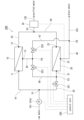
- FIG. 1 is a diagram illustrating a reverse osmosis membrane water purifier according to a first embodiment.
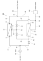
- FIG. FIG. 10 is a diagram illustrating a reverse osmosis membrane water purifier according to a second embodiment.
- FIG. 11 is a diagram illustrating a reverse osmosis membrane water purifier according to a third embodiment.
- FIG. 10 is a diagram illustrating a reverse osmosis membrane water purifier according to a fourth embodiment.
- FIG. 13 is a diagram illustrating a reverse osmosis membrane water purifier according to a fifth embodiment.
- 1 is a graph showing the relationship between the TDS concentration in raw water and the flow rate of permeated water.
- FIG. 13 is a diagram illustrating a reverse osmosis membrane water purifier according to a sixth embodiment.
- FIG. 13 is a diagram illustrating a reverse osmosis membrane water purifier according to another embodiment.
- Embodiments 1 to 6 embodying the reverse osmosis membrane water purifier according to the present disclosure will be described with reference to the drawings.
- the reverse osmosis membrane water purifier according to each of the following embodiments uses tap water as raw water and produces purified water from this raw water.
- examples of raw water include well water and rainwater.
- the purified water is obtained by processing the raw water through a reverse osmosis membrane (reverse osmosis membrane processing).
- the reverse osmosis membrane water purifier 100 includes a water supply section 101, a first drain section 102, and a second drain section 103.
- the reverse osmosis membrane water purifier 100 is supplied with raw water from the water supply section 101.
- the water supply section 101 is connected to a water supply source (not shown) on the upstream side.
- the water supply section 101 is provided with a pump 101A for applying reverse osmosis pressure to the raw water.
- the downstream end of the water supply section 101 is a branch section P1, to which the upstream ends of a first inlet water passage section 41 and a second inlet water passage section 42, which will be described later, are connected.
- Raw water which is tap water, usually contains dissolved solids such as calcium, magnesium, and sodium.
- the reverse osmosis membrane water purifier 100 discharges purified water from the first drainage section 102.
- the purified water has a lower amount of dissolved solids than the raw water by treating the raw water with a reverse osmosis membrane.
- TDS concentration total dissolved solids concentration
- the reverse osmosis membrane water purifier 100 discharges wastewater from the second drainage section 103.
- the wastewater is the water remaining after the purified water is extracted from the raw water.
- the wastewater has a higher TDS concentration than the raw water.
- the reverse osmosis membrane water purifier 100 comprises reverse osmosis membrane modules (first reverse osmosis membrane module 10, second reverse osmosis membrane module 20), a flow rate measuring unit 30, water passage units (first inlet water passage unit 41, second inlet water passage unit 42, first outlet water passage unit 43, second outlet water passage unit 44, third outlet water passage unit 45, fourth outlet water passage unit 46, first branch water passage unit 47, second branch water passage unit 48), and switching units (first switching unit 51, second switching unit 52, third switching unit 53).
- the reverse osmosis membrane modules 10 and 20 filter raw water by a so-called cross-flow method having a reverse osmosis membrane (not shown).
- the reverse osmosis membrane modules 10 and 20 perform reverse osmosis membrane treatment on the introduced water.
- Each reverse osmosis membrane module 10, 20 separates water that has permeated the reverse osmosis membrane during the reverse osmosis membrane process (permeated water) from water that has not permeated (non-permeated water).
- each reverse osmosis membrane module 10 has an inlet 11, 21, a first outlet 12, 22, and a second outlet 13, 23.
- Each reverse osmosis membrane module 10, 20 introduces water from the inlet 11, 21.
- Each reverse osmosis membrane module 10, 20 discharges permeated water from the first outlet 12, 22 and discharges non-permeated water from the second outlet 13, 23.
- the permeated water discharged from the first outlet 12, 22 has a reduced TDS concentration compared to the water introduced from the inlet 11, 21.
- the non-permeated water discharged from the second outlet 13, 23 has a higher TSD concentration than the water introduced from the inlet 11, 21.
- the permeated water discharged from the first reverse osmosis membrane module 10 and the permeated water discharged from the second reverse osmosis membrane module 20 join together and flow through the first drainage section 102, and are discharged as purified water.
- the non-permeated water discharged from the first reverse osmosis membrane module 10 is discharged as wastewater from the second drainage section 103 when the water flows through the parallel flow paths described below.
- the non-permeated water discharged from the first reverse osmosis membrane module 10 is introduced from the inlet 21 into the second reverse osmosis membrane module 20 when the water flows through the serial flow paths described below, and is again subjected to reverse osmosis membrane treatment in the second reverse osmosis membrane module 20.
- the non-permeated water discharged from the second reverse osmosis membrane module 20 is discharged as wastewater from the second drainage section 103.
- the flow rate measuring unit 30 measures the flow rate of the permeate, which is the water that has permeated the reverse osmosis membrane in each reverse osmosis membrane module 10, 20.
- the flow rate measuring unit 30 is configured to have a known flow rate measuring means, etc.
- the flow rate measuring unit 30 is disposed in the first drainage section 102. This allows the flow rate measuring unit 30 to measure at one location the total flow rate of the permeate discharged from each of the multiple reverse osmosis membrane modules 10, 20, which is the sum of the flow rates of each permeate.
- the flow rate of the permeate measured by the flow rate measuring unit 30 is directly the flow rate of the purified water.
- the water passage section forms a flow path that connects the first reverse osmosis membrane module 10 and the second reverse osmosis membrane module 20 in parallel and in series.
- the water passage section is composed of a first inlet water passage section 41, a second inlet water passage section 42, a first outlet water passage section 43, a second outlet water passage section 44, a third outlet water passage section 45, a fourth outlet water passage section 46, a first branch water passage section 47, and a second branch water passage section 48.
- the first inlet water passage section 41 and the second inlet water passage section 42 each form a flow path branching off from the branch section P1, which is the downstream end of the water supply section 101.
- the first inlet water passage section 41 is connected to the branch section P1 at its upstream end and to the inlet 11 of the first reverse osmosis membrane module 10 at its downstream end.
- Raw water supplied from the water supply section 101 flows through the flow path formed by the first inlet water passage section 41.
- the raw water that flows from the water supply section 101 into the first inlet water passage section 41 is introduced into the first reverse osmosis membrane module 10 from the inlet 11.
- the second inlet water passage 42 is connected at its upstream end to the branch section P1, and at its downstream end to the inlet 21 in the second reverse osmosis membrane module 20.
- Raw water supplied from the water supply section 101 flows through the flow path formed by the second inlet water passage 42.
- the raw water that flows from the water supply section 101 into the second inlet water passage 42 is introduced into the second reverse osmosis membrane module 20 from the inlet 21.
- the second inlet water passage 42 is provided with a junction P2.
- the downstream end of the second branch water passage 48 is connected to the junction P2. This allows water flowing through the second branch water passage 48 to flow into the flow path formed by the second inlet water passage 42.
- a first switch 51 which will be described later, is provided upstream of the junction P2 in the second inlet water passage 42.
- the first discharge water passage 43 has an upstream end connected to the first discharge port 12 in the first reverse osmosis membrane module 10.
- the downstream end of the first discharge water passage 43 is connected to the junction P3, which corresponds to the upstream end of the first drainage section 102.
- Permeated water discharged from the first reverse osmosis membrane module 10 flows through the flow path formed by the first discharge water passage 43.
- the permeated water that flows through the first discharge water passage 43 flows from the junction P3 into the first drainage section 102 and is discharged as purified water.
- the second discharge water passage 44 has an upstream end connected to the first discharge port 22 in the second reverse osmosis membrane module 20.
- the downstream end of the second discharge water passage 44 is connected to the junction P3, which is the upstream end of the first drainage section 102.
- the permeated water discharged from the second reverse osmosis membrane module 20 flows through the flow path formed by the second discharge water passage 44.
- the permeated water that flows through the second discharge water passage 44 flows from the junction P3 into the first drainage section 102 and is discharged as purified water.
- the third discharge water passage 45 has an upstream end connected to the second discharge port 13 in the first reverse osmosis membrane module 10.
- the downstream end of the third discharge water passage 45 is the branching section P4.
- the upstream ends of the first branching water passage 47 and the second branching water passage 48 are connected to the branching section P4.
- Non-permeated water discharged from the first reverse osmosis membrane module 10 flows through the flow path formed by the third discharge water passage 45.
- the non-permeated water that has flowed through the third discharge water passage 45 flows from the branching section P4 into either the first branching water passage 47 or the second branching water passage 48.
- the fourth discharge water passage 46 has an upstream end connected to the second discharge port 23 of the second reverse osmosis membrane module 20. Non-permeated water discharged from the second reverse osmosis membrane module 20 flows through the flow path formed by the fourth discharge water passage 46.
- the downstream end of the fourth discharge water passage 46 is connected to the junction P5, which corresponds to the upstream end of the second drainage section 103.
- the non-permeated water that has flowed through the fourth discharge water passage 46 flows from the junction P5 into the second drainage section 103 and is discharged as drainage.
- the first branch water passage section 47 and the second branch water passage section 48 each form a flow path branching from the diverging section P4, which is the downstream end of the third discharge water passage section 45.
- the first branch water passage section 47 is connected to the diverging section P4 at its upstream end and to the merging section P5 at its downstream end.
- Non-permeated water discharged from the first reverse osmosis membrane module 10 to the third discharge water passage section 45 flows through the flow path formed by the first branch water passage section 47.
- the non-permeated water that flows from the diverging section P4 into the first branch water passage section 47 flows from the merging section P5 into the second drain section 103 and is discharged as wastewater.
- the first branch water passage section 47 is provided with a second switching section 52, which will be described later.
- the second branch water passage section 48 is connected at its upstream end to the diversion section P4 and at its downstream end to the junction section P2.
- Non-permeated water discharged from the first reverse osmosis membrane module 10 to the third discharge water passage section 45 flows through the flow path formed by the second branch water passage section 48.
- the non-permeated water that flows from the diversion section P4 into the second branch water passage section 48 flows from the junction section P2 into the second inlet water passage section 42 and is introduced into the second reverse osmosis membrane module 20 from the inlet 21.
- the second branch water passage section 48 is provided with a third switching section 53, which will be described later.
- the water passage sections form parallel flow paths and serial flow paths.
- the parallel flow paths are flow paths that connect the first reverse osmosis membrane module 10 and the second reverse osmosis membrane module 20 in parallel.
- the parallel flow paths are formed by the water passage sections of the first inlet water passage section 41, the second inlet water passage section 42, the first outlet water passage section 43, the second outlet water passage section 44, the third outlet water passage section 45, the fourth outlet water passage section 46, the first branch water passage section 47, and the second branch water passage section 48, excluding the second branch water passage section 48.
- the serial flow path is a flow path that connects the first reverse osmosis membrane module 10 and the second reverse osmosis membrane module 20 in series on the non-permeated water side.
- the serial flow path is formed by the water passage parts of the first inlet water passage part 41, the second inlet water passage part 42, the first outlet water passage part 43, the second outlet water passage part 44, the third outlet water passage part 45, the fourth outlet water passage part 46, the first branch water passage part 47, and the second branch water passage part 48, excluding the second inlet water passage part 42 and the first branch water passage part 47 that are upstream of the confluence part P2.
- the switching unit switches the water flow state in the water flow unit.
- the water flow state in the water flow unit is one of two water flow states: one in which water can flow through the parallel flow paths, and one in which water can flow through the serial flow paths.
- the switching unit freely switches between these water flow states: one in which water can flow through the parallel flow paths, and one in which water can flow through the serial flow paths.
- the switching section is configured to have a first switching section 51, a second switching section 52, and a third switching section 53.
- Each switching section 51, 52, 53 is configured to have a known on-off valve such as a ball valve or a globe valve.
- the first switching section 51 is provided in the second inlet water passage section 42.
- the first switching section 51 can freely open and close the flow path formed by the second inlet water passage section 42.
- the second switching section 52 is provided in the first branch water passage section 47.
- the second switching section 52 can freely open and close the flow path formed by the first branch water passage section 47.
- the third switching section 53 is provided in the second branch water passage section 48.
- the third switching section 53 can freely open and close the flow path formed by the second branch water passage section 48.
- the opening and closing of each flow path by each of these switching units 51, 52, 53 is performed by a worker who installs and sets up the reverse osmosis membrane water purifier 100, a user who actually uses the reverse osmosis membrane water purifier 100, etc., by manually operating each of the switching units 51, 52, 53.
- the workers who install and set up the reverse osmosis membrane water purifier 100, the users who actually use the reverse osmosis membrane water purifier 100, and the operators who operate each part of the device will be referred to simply as users, etc.
- each switch 51, 52, 53 As a specific operation for switching the water flow state, the user operates each switch 51, 52, 53 as follows. When switching to a state allowing water to flow through the parallel flow path, the user opens the first switch 51 and the second switch 52, and closes the third switch 53. When switching to a state allowing water to flow through the serial flow path, the user closes the first switch 51 and the second switch 52, and opens the third switch 53.
- the reverse osmosis membrane water purifier 100 is supplied with raw water from a water supply source (not shown).
- the supplied raw water is pressurized by the pump 101A in the water supply section 101 and flows into the water passage section.
- the water passage state in the water passage section is a state in which water can pass through the parallel flow paths, the raw water is divided into the first inlet water passage section 41 and the second inlet water passage section 42 in the branch section P1.
- the first switching section 51 in the second inlet water passage section 42 is opened, and the second inlet water passage section 42 is capable of passing water. Therefore, the raw water branches and flows to both the first inlet water passage section 41 and the second inlet water passage section 42, and is introduced into each reverse osmosis membrane module 10, 20 from each inlet 11, 21.
- the first switch section 51 in the second inlet water passage section 42 is closed and water cannot flow through the second inlet water passage section 42. Therefore, the raw water flows only into the first inlet water passage section 41 in the diversion section P1 and is introduced only into the first reverse osmosis membrane module 10. In this case, non-permeated water produced in the first reverse osmosis membrane module 10 is introduced into the second reverse osmosis membrane module 20.
- each reverse osmosis membrane module 10, 20 reverse osmosis membrane treatment is performed on the introduced water.
- each reverse osmosis membrane module 10, 20 separates the introduced water into permeated water that has passed through the reverse osmosis membrane and non-permeated water that has not passed through.
- the permeated water generated in the reverse osmosis membrane treatment in each reverse osmosis membrane module 10, 20 is discharged from the first outlet 12, 22 to the first discharge water passage section 43 and the second discharge water passage section 44, respectively, and merges at the junction P3 and flows into the first drain section 102.
- the permeated water that has flowed through the first drain section 102 is discharged as purified water.
- the non-permeated water generated in each reverse osmosis membrane module 10, 20 is discharged from the second outlet 13, 23 to the third discharge water passage section 45 and the fourth discharge water passage section 46, respectively.
- the second switching section 52 is open and the third switching section 53 is closed, so that the first branch water passage section 47 is passable and the second branch water passage section 48 is not passable.
- the non-permeated water discharged from the first reverse osmosis membrane module 10 to the third discharge water passage section 45 flows only into the first branch water passage section 47 at the division section P4, passes through the first branch water passage section 47, and flows into the second drain section 103 from the confluence section P5.
- the second switching section 52 is closed and the third switching section 53 is open, so that the first branch water passage section 47 is not able to pass water and the second branch water passage section 48 is able to pass water. Therefore, when water can pass through the serial flow path, the non-permeated water discharged from the first reverse osmosis membrane module 10 to the third discharge water passage section 45 flows only into the second branch water passage section 48 at the diversion section P4. The non-permeated water that has flowed through the second branch water passage section 48 flows into the second inlet water passage section 42 at the junction section P2 and is introduced into the second reverse osmosis membrane module 20 from the inlet 21.
- the non-permeated water discharged from the first reverse osmosis membrane module 10 is treated by the reverse osmosis membrane in the second reverse osmosis membrane module 20 and is separated again into permeated water and non-permeated water.
- the non-permeated water discharged from the second reverse osmosis membrane module 20 to the fourth discharge water passage 46 flows through the fourth discharge water passage 46 and flows into the second drainage section 103 from the junction P5.
- the non-permeated water that flows into the second drainage section 103 is discharged as wastewater.
- the user selects whether the water flow state in the water flow section is to be used in a state in which water can flow through the parallel flow path or the serial flow path. This selection is made by the user of the reverse osmosis membrane water purifier 100 from the viewpoint of which flow rate of the permeated water can be obtained. Specifically, in the case of this embodiment, the user of the reverse osmosis membrane water purifier 100 performs a switching operation of each switching unit 51, 52, 53, and actually passes water through both the parallel flow path and the serial flow path. The user selects the water flow state that shows the larger value of the actual measured values of the permeated water flow rate actually measured by the flow rate measuring unit 30 in each water flow state. The user performs a switching operation of each switching unit 51, 52, 53 to set the water flow state in which the selected larger flow rate of the permeated water can be obtained.
- the flow rate measuring unit 30 is provided in the first drainage section 102.
- the permeated water discharged from each of the first reverse osmosis membrane module 10 and the second reverse osmosis membrane module 20 joins and flows through this first drainage section 102. Therefore, the flow rate measuring unit 30 does not need to separately measure the flow rate of the permeated water discharged from each of the first reverse osmosis membrane module 10 and the second reverse osmosis membrane module 20, and can measure the total amount of permeated water generated in the reverse osmosis membrane water purifier 100.
- the reverse osmosis membrane water purifier 100 includes a plurality of reverse osmosis membrane modules 10, 20, a flow rate measuring unit 30, water flow units 41, 42, 43, 44, 45, 46, 47, 48, and switching units 51, 52, 53.
- the reverse osmosis membrane modules 10, 20 process the introduced water to pass it through the reverse osmosis membrane, and separate the water into permeated water that has passed through the reverse osmosis membrane and non-permeated water that has not passed through the reverse osmosis membrane, and discharge the water.
- the flow rate measuring unit 30 measures the flow rate of the permeated water that has passed through the reverse osmosis membrane.
- the water flow units 41, 42, 43, 44, 45, 46, 47, 48 form a parallel flow path in which the reverse osmosis membrane modules 10, 20 are connected in parallel, and a serial flow path in which the reverse osmosis membrane modules 10, 20 are connected in series on the non-permeated water side.
- the switching units 51, 52, and 53 freely switch between a water-passing state in which water can pass through a parallel flow path in which multiple reverse osmosis membrane modules 10 and 20 are connected in parallel, and a water-passing state in which water can pass through a serial flow path in which multiple reverse osmosis membrane modules 10 and 20 are connected in series.
- the reverse osmosis membrane water purifier 100 can measure the actual flow rate of the permeated water using the flow rate measuring unit 30, and by switching the switching units 51, 52, and 53, it can be used by switching between a state in which water can pass through a parallel flow path in which multiple reverse osmosis membrane modules 10, 20 are connected in parallel, and a state in which water can pass through a serial flow path in which multiple reverse osmosis membrane modules 10, 20 are connected in series. Therefore, the reverse osmosis membrane water purifier 100 can select and use a water passing state that allows a larger flow rate of permeated water based on the actually measured flow rate of permeated water. Therefore, the reverse osmosis membrane water purifier 100 can easily obtain a larger flow rate of permeated water.
- the reverse osmosis membrane water purifier 200 is similar to that of the first embodiment in that it includes a flow rate measuring unit 30 that measures the flow rate of the permeated water.
- the reverse osmosis membrane water purifier 200 differs from the first embodiment in that it includes switching units 251, 252, and 253 instead of the switching units 51, 52, and 53 according to the first embodiment, and further includes a control unit 260.
- the same components as those in the first embodiment are denoted by the same reference numerals, and duplicated description will be omitted.
- the reverse osmosis membrane water purifier 200 includes a reverse osmosis membrane module (first reverse osmosis membrane module 10, second reverse osmosis membrane module 20), a flow rate measuring unit 30, a water passage unit (first inlet water passage unit 41, second inlet water passage unit 42, first outlet water passage unit 43, second outlet water passage unit 44, third outlet water passage unit 45, fourth outlet water passage unit 46, first branch water passage unit 47, second branch water passage unit 48), a switching unit (first switching unit 251, second switching unit 252, third switching unit 253), and a control unit 260.
- the switching unit includes a first switching unit 251, a second switching unit 252, and a third switching unit 253.
- Each switching unit 251, 252, and 253 includes an electric valve that is driven by an actuator such as a solenoid or a motor.
- the control unit 260 controls the switching of the water flow state by each of the switching units 251, 252, and 253.
- the control unit 260 is mainly a microcontroller, and is configured with an arithmetic device such as a CPU (Central Processing Unit), and storage means such as a RAM and a ROM.
- the control unit 260 is connected to the pump 101A, the flow rate measurement unit 30, and each of the switching units 251, 252, and 253. Based on the measurement result of the flow rate measurement unit 30, the control unit 260 compares the flow rate of the permeated water when the water flows through the parallel flow path with the flow rate of the permeated water when the water flows through the serial flow path.
- control unit 260 executes control to switch to the water flow state with the higher flow rate of the permeated water.
- the control unit 260 executes control to switch the water flow state according to a program for setting the reverse osmosis membrane water purifier 200 that is stored in advance in a storage means (not shown).
- the control unit 260 controls the switching of the water flow state as follows.
- the control unit 260 controls the drive of each of the switching units 251, 252, and 253, and sequentially switches the water flow state between two states: a state in which water can flow through the parallel flow path, and a state in which water can flow through the serial flow path.
- the control unit 260 maintains each water flow state for a predetermined time, and during that time drives the pump 101A to pass water.
- the flow rate measurement unit 30 measures the flow rate of the permeated water in each water flow state.
- Each measurement result by the flow rate measurement unit 30 is stored in a storage means or the like in the control unit 260.
- the control unit 260 refers to the storage means or the like and compares each measurement result by the flow rate measurement unit 30. The control unit 260 then controls the drive of each of the switching units 251, 252, and 253, and switches to the water flow state in which a greater flow rate of permeated water is measured.
- the reverse osmosis membrane water purifier 200 according to the second embodiment of the above configuration has the same effect as the reverse osmosis membrane water purifier 100 according to the first embodiment.
- the reverse osmosis membrane water purifier 200 includes a control unit 260 that controls the switching of the water flow state by the switching units 251, 252, and 253. Based on the measurement results by the flow rate measurement unit 30, the control unit 260 compares the flow rate of the permeated water when the water is passed through the parallel flow paths with the flow rate of the permeated water when the water is passed through the serial flow paths, and executes control to switch to the water flow state with the higher permeated water flow rate.
- the reverse osmosis membrane water purifier 200 automatically switches to the water flow state with the higher permeated water flow rate by driving and controlling each switching unit 251, 252, and 253 by the control unit 260. Therefore, the reverse osmosis membrane water purifier 200 can reduce the effort of the user, etc., compared to the first embodiment. Therefore, the reverse osmosis membrane water purifier 200 can obtain a larger flow rate of the permeated water more easily.
- the reverse osmosis membrane water purifier 300 according to the third embodiment differs from the first embodiment in that it includes a concentration measuring unit 370 instead of the flow rate measuring unit 30 according to the first embodiment.
- concentration measuring unit 370 instead of the flow rate measuring unit 30 according to the first embodiment.
- the concentration measuring unit 370 measures the TDS concentration of non-permeated water, which is water that does not pass through the reverse osmosis membrane in the reverse osmosis membrane treatment in each reverse osmosis membrane module 10, 20.
- the concentration measuring unit 370 has a measuring means, such as electrical conductivity, that measures a value that changes depending on the concentration of dissolved solids in the water.
- the concentration measuring unit 370 calculates the TDS concentration based on the measurement value of this measuring means.
- the concentration measuring unit 370 is provided in the second drainage unit 103.
- the selection of which of the parallel flow paths and the serial flow paths to use in a water-passable state is made from the perspective of which can obtain a larger flow rate of permeated water, as in the above embodiments.
- the TDS concentration of the non-permeated water measured by the concentration measuring unit 370 is used as an index for selecting the water-passing state, similar to the flow rate of permeated water measured by the flow rate measuring unit 30 in embodiments 1 and 2.
- the user of the reverse osmosis membrane water purifier 300 switches the switching units 51, 52, and 53 to actually pass water through both the parallel flow paths and the serial flow paths.
- the user selects the water passing state that shows the higher TDS concentration value among the actual measured values of the TDS concentration of the non-permeated water actually measured by the concentration measuring unit 370 in each water passing state.
- the user switches the switching units 51, 52, and 53 to select the water passing state that shows the higher TDS concentration.
- non-permeated water has a higher TDS concentration than raw water.
- the TDS concentration in the non-permeated water increases according to the amount of permeated water produced relative to the amount of raw water. For this reason, when reverse osmosis membrane treatment is performed on raw water supplied at a constant flow rate, a higher TDS concentration in the non-permeated water indicates that more permeated water is being produced. Therefore, the TDS concentration in the non-permeated water can be suitably used as an indicator of the amount of permeated water produced.
- the reverse osmosis membrane water purifier 300 includes a plurality of reverse osmosis membrane modules 10, 20, a concentration measuring unit 370, water flow units 41, 42, 43, 44, 45, 46, 47, 48, and switching units 51, 52, 53.
- the reverse osmosis membrane modules 10, 20 process the introduced water to pass it through the reverse osmosis membrane, and separate the water into permeated water that has passed through the reverse osmosis membrane and non-permeated water that has not passed through the reverse osmosis membrane and discharge the water.
- the concentration measuring unit 370 measures the TDS concentration in the non-permeated water that has not passed through the reverse osmosis membrane.
- the water flow units 41, 42, 43, 44, 45, 46, 47, 48 form a parallel flow path in which the reverse osmosis membrane modules 10, 20 are connected in parallel, and a serial flow path in which the reverse osmosis membrane modules 10, 20 are connected in series on the non-permeated water side.
- the switching units 51, 52, and 53 freely switch between a water-passing state in which water can pass through a parallel flow path in which multiple reverse osmosis membrane modules 10 and 20 are connected in parallel, and a water-passing state in which water can pass through a serial flow path in which multiple reverse osmosis membrane modules 10 and 20 are connected in series.
- the reverse osmosis membrane water purifier 300 can measure the TDS concentration of the non-permeated water by the concentration measuring unit 370, and can be used by switching between a state in which water can pass through a parallel flow path in which multiple reverse osmosis membrane modules 10, 20 are connected in parallel, and a state in which water can pass through a serial flow path in which multiple reverse osmosis membrane modules 10, 20 are connected in series, by switching the switching units 51, 52, 53.
- the reverse osmosis membrane water purifier 300 can select and use a water passing state in which more permeated water can be obtained based on the TDS concentration value, which is a value measured by the concentration measuring unit 370 and changes depending on the separation ratio of the permeated water to the raw water. Therefore, the reverse osmosis membrane water purifier 300 can easily obtain more permeated water.
- the reverse osmosis membrane water purifier 400 is similar to the third embodiment in that it includes a concentration measuring unit 370 that measures the TDS concentration of non-permeated water.
- the reverse osmosis membrane water purifier 400 differs from the third embodiment in that it includes switching units 251, 252, and 253 similar to those of the second embodiment instead of the switching units 51, 52, and 53, and further includes a control unit 460.
- the same components as those of the above-mentioned embodiments are denoted by the same reference numerals, and duplicated description will be omitted.
- the reverse osmosis membrane water purifier 400 includes a reverse osmosis membrane module (first reverse osmosis membrane module 10, second reverse osmosis membrane module 20), a concentration measurement unit 370, a water passage unit (first inlet water passage unit 41, second inlet water passage unit 42, first outlet water passage unit 43, second outlet water passage unit 44, third outlet water passage unit 45, fourth outlet water passage unit 46, first branch water passage unit 47, second branch water passage unit 48), a switching unit (first switching unit 251, second switching unit 252, third switching unit 253), and a control unit 460.
- the switching unit has the same configuration as in the second embodiment, and is configured to include a first switching unit 251, a second switching unit 252, and a third switching unit 253.
- the control unit 460 controls the switching of the water flow state by each of the switching units 251, 252, and 253.
- the control unit 460 is configured to have, for example, a microcontroller as a main component, a calculation device, a storage means, etc., as in the control unit 260 according to the second embodiment.
- the control unit 460 is connected to the pump 101A, the concentration measurement unit 370, and each of the switching units 251, 252, and 253. Based on the measurement results of the concentration measurement unit 370, the control unit 460 compares the TDS concentration of the non-permeated water when water is passed through the parallel flow paths with the TDS concentration of the non-permeated water when water is passed through the serial flow paths.
- control unit 460 executes control to switch to the water flow state in which the TDS concentration of the non-permeated water is higher.
- the control unit 460 executes control to switch the water flow state according to a program for setting the reverse osmosis membrane water purifier 400, which is stored in advance in a storage means (not shown), etc.
- the control unit 460 controls the switching of the water flow state as follows.
- the control unit 460 controls the drive of each of the switching units 251, 252, and 253, and sequentially switches the water flow state between two states: a state in which water can flow through the parallel flow path, and a state in which water can flow through the serial flow path.
- the control unit 460 maintains each water flow state for a predetermined time, and during that time drives the pump 101A to pass water.
- the concentration measurement unit 370 measures the TDS concentration of the non-permeated water in each water flow state.
- Each measurement result by the concentration measurement unit 370 is stored in a storage means or the like in the control unit 460.
- the control unit 460 refers to the storage means or the like and compares each measurement result by the concentration measurement unit 370. The control unit 460 then controls the drive of each of the switching units 251, 252, and 253, and switches to the water flow state in which a higher TDS concentration was measured.
- the reverse osmosis membrane water purifier 400 according to the fourth embodiment of the above configuration has the same effect as the reverse osmosis membrane water purifier 300 according to the third embodiment.
- the reverse osmosis membrane water purifier 400 includes a control unit 460 that controls the switching of the water flow state by the switching units 251, 252, and 253. Based on the measurement results by the concentration measurement unit 370, the control unit 460 compares the TDS concentration of the non-permeated water in the state where the water flows through the parallel flow paths with the TDS concentration of the non-permeated water in the state where the water flows through the serial flow paths, and executes control to switch to the water flow state with the higher TDS concentration.
- the reverse osmosis membrane water purifier 400 automatically switches to the water flow state with the higher TDS concentration of the non-permeated water by controlling the driving of each switching unit 251, 252, and 253 by the control unit 460. Therefore, the reverse osmosis membrane water purifier 400 can reduce the effort of the user, etc., compared to the third embodiment. Therefore, the reverse osmosis membrane water purifier 400 can obtain a larger flow rate of permeated water more easily.
- the reverse osmosis membrane water purifier 500 includes a concentration measuring unit 370, similar to the third embodiment.
- the reverse osmosis membrane water purifier 500 differs from the third embodiment in that the concentration measuring unit 370 measures the TDS concentration of the raw water.
- the same components as those in the above-mentioned embodiments are denoted by the same reference numerals, and duplicated description will be omitted.
- the inventors of the present application have found that, under certain conditions, a greater flow rate of permeate can be obtained when multiple reverse osmosis membrane modules are connected in parallel than when they are connected in series. This finding is that, when the TDS concentration value in the water before reverse osmosis membrane treatment is less than a certain threshold value Th, a greater flow rate of permeate can be obtained when connected in parallel than when connected in series.
- the TDS concentration of the raw water measured by the concentration measurement unit 370 is used as an index when selecting the water flow state.
- the graph in Figure 6 shows the results of an experiment conducted by the inventors of the present application.
- This graph shows the relationship between the TDS concentration of water before reverse osmosis membrane treatment and the flow rate of permeate for each of the cases where multiple reverse osmosis membrane modules are connected in parallel and in series.
- the TDS concentration of the water before treatment is about 300 ppm
- a higher flow rate of permeate can be obtained by passing the water through the parallel flow path when the TDS concentration is low
- the TDS concentration is high
- a higher flow rate of permeate can be obtained by passing the water through the serial flow path.
- the raw water when the raw water is tap water from China or some parts of Europe, which has a relatively high TDS concentration, it is believed that more permeate can be obtained by passing the water through the serial flow path.
- the raw water when the raw water is tap water from some parts of Japan, which has a relatively low TDS concentration, it is believed that more permeate can be obtained by passing the water through the parallel flow path.
- the threshold value Th can be set based on the correlation between the TDS concentration and the permeate flow rate experimentally determined in advance. Specifically, in setting the threshold value Th, first, the permeate flow rate is experimentally measured when the raw water is passed through the reverse osmosis membrane module using the TDS concentration as a parameter in both the serial and parallel connection cases. Then, based on the measurement results, the threshold value Th is set to the boundary value of the TDS concentration at which a greater permeate flow rate is obtained in the parallel connection case than in the serial connection case. The detailed mechanism by which a greater permeate flow rate is obtained in the parallel connection case than in the serial connection case under specified conditions is unknown. However, it is believed that the permeate flow rate changes due to the influence of the state of formation of the concentration polarization layer on the surface of the reverse osmosis membrane in the reverse osmosis membrane module.
- the concentration polarization layer is affected by the flow of water flowing over the reverse osmosis membrane surface, and its state of formation changes. In other words, the state of formation of the concentration polarization layer is affected by various factors, not just the TDS concentration.
- the flow of water over the reverse osmosis membrane surface can change depending on the support structure of the reverse osmosis membrane in the reverse osmosis membrane module, the structure of the module itself, such as the housing shape in the reverse osmosis membrane module, and the performance of the pump that applies reverse osmosis pressure to the raw water.
- the flow rate of the permeated water is not simply correlated with the TDS concentration, but can also be influenced by the design specifications of the reverse osmosis membrane water purifier. Therefore, it is advisable to set the threshold value Th of the TDS concentration based on the correlation between the TDS concentration and the flow rate of the permeated water, which is experimentally determined in advance for each model of reverse osmosis membrane water purifier. Setting the threshold value Th in this way is preferable because a clear boundary value can be set as the threshold value Th.
- the threshold value Th may be set within this range without conducting experiments, etc. Setting the threshold value Th in this way is preferable as it avoids the trouble of conducting experiments, etc. for each model. Specifically, the threshold value Th may be set within the following range, for example.
- the preferred setting range of the threshold value Th can be any combination of the upper and lower limit values of the TDS concentration shown below.
- the lower limit value is preferably set to a TDS concentration of, for example, 200 ppm or more, and more preferably set to 250 ppm or more.
- the upper limit value of the threshold value Th is preferably set to a TDS concentration of, for example, 400 ppm or less, and more preferably set to 350 ppm or less. If the TDS concentration threshold value Th is within the range of the combination of the above upper and lower limits, the water flow state can be appropriately selected, and more purified water can be obtained. In this embodiment, an example is shown in which the threshold value Th is set to 300 ppm.
- the configuration, functions, etc. of the concentration measurement unit 370 are the same as those of the third and fourth embodiments.
- the concentration measurement unit 370 in the fifth embodiment measures the TDS concentration of the raw water.
- the concentration measurement unit 370 is provided in the water supply unit 101 as shown in FIG. 5.
- the reverse osmosis membrane water purifier 500 the selection of which of the parallel flow paths and the serial flow paths is to be used in a state in which water can pass is made from the viewpoint of which of the parallel flow paths can obtain a larger flow rate of the permeated water, as in the above-mentioned embodiments.
- the TDS concentration of the raw water measured by the concentration measurement unit 370 is used as an index for selecting the water passing state, as is the flow rate of the permeated water measured by the flow rate measurement unit 30 in the first and second embodiments.
- the user measures the TDS concentration of the raw water flowing through the water supply unit 101 using the concentration measurement unit 370.
- the water flow state in the water flow unit does not matter, and it can be either a parallel or serial water flow state.
- the user determines whether the measured TDS concentration is less than the preset threshold value Th of 300 ppm. If the measured TDS concentration is not less than the preset threshold value Th, the user selects to use the device in a state where water can flow through the serial flow path. The user then switches the switching units 51, 52, and 53 to set the selected water flow state.
- the inventors of the present application have experimentally found that when the TDS concentration of the raw water is below a predetermined threshold, a greater permeate flow rate can be obtained by using the parallel flow paths in a state where water can flow through them than by using the serial flow paths in a state where water can flow through them. Therefore, the TDS concentration value of the raw water is suitable as an indicator for obtaining a larger amount of permeate.
- the reverse osmosis membrane water purifier 500 includes a plurality of reverse osmosis membrane modules 10, 20, a concentration measuring unit 370, water flow units 41, 42, 43, 44, 45, 46, 47, 48, and switching units 51, 52, 53.
- the reverse osmosis membrane modules 10, 20 process the introduced water to pass through the reverse osmosis membrane, and separate the water into permeated water that has passed through the reverse osmosis membrane and non-permeated water that has not passed through the reverse osmosis membrane and discharge the separated water.
- the concentration measuring unit 370 measures the TDS concentration in the water before being introduced into the reverse osmosis membrane modules 10, 20, i.e., the raw water.
- the water flow units 41, 42, 43, 44, 45, 46, 47, 48 form a parallel flow path in which the reverse osmosis membrane modules 10, 20 are connected in parallel, and a serial flow path in which the reverse osmosis membrane modules 10, 20 are connected in series on the non-permeated water side.
- the switching units 51, 52, and 53 freely switch between a water-passing state in which water can pass through a parallel flow path in which multiple reverse osmosis membrane modules 10 and 20 are connected in parallel, and a water-passing state in which water can pass through a serial flow path in which multiple reverse osmosis membrane modules 10 and 20 are connected in series.
- the reverse osmosis membrane water purifier 500 can measure the TDS concentration of the raw water using the concentration measuring unit 370, and by switching the switching units 51, 52, and 53, it can be used by switching between a state in which water can pass through a parallel flow path in which multiple reverse osmosis membrane modules 10, 20 are connected in parallel, and a state in which water can pass through a serial flow path in which multiple reverse osmosis membrane modules 10, 20 are connected in series. Therefore, the reverse osmosis membrane water purifier 500 can select and use a water passing state that allows more permeated water to be obtained based on the value of the TDS concentration of the raw water measured by the concentration measuring unit 370. Therefore, the reverse osmosis membrane water purifier 500 can easily obtain more permeated water.
- the reverse osmosis membrane water purifier 600 is similar to the fifth embodiment in that it includes a concentration measuring unit 370 that measures the TDS concentration of raw water.
- the reverse osmosis membrane water purifier 600 differs from the fifth embodiment in that it includes switching units 251, 252, and 253 similar to those of the second embodiment instead of the switching units 51, 52, and 53, and further includes a control unit 660.
- the same components as those of the above-mentioned embodiments are denoted by the same reference numerals, and duplicated description will be omitted.
- the reverse osmosis membrane water purifier 600 includes a reverse osmosis membrane module (first reverse osmosis membrane module 10, second reverse osmosis membrane module 20), a concentration measurement unit 370, a water passage unit (first inlet water passage unit 41, second inlet water passage unit 42, first outlet water passage unit 43, second outlet water passage unit 44, third outlet water passage unit 45, fourth outlet water passage unit 46, first branch water passage unit 47, second branch water passage unit 48), a switching unit (first switching unit 251, second switching unit 252, third switching unit 253), and a control unit 660.
- the switching unit has the same configuration as in the second embodiment, and is configured to include a first switching unit 251, a second switching unit 252, and a third switching unit 253.
- the control unit 660 controls the switching of the water flow state by each of the switching units 251, 252, and 253.
- the control unit 660 is configured to have, for example, a microcontroller as a main component, a calculation device, a storage means, etc., similar to the control unit 260 in embodiment 2.
- the control unit 660 is connected to the pump 101A, the concentration measurement unit 370, and each of the switching units 251, 252, and 253.
- the control unit 660 compares the TDS concentration of the raw water, which is the measurement result of the concentration measurement unit 370, with a predetermined threshold value Th (for example, 300 ppm).
- Th for example, 300 ppm
- the control unit 660 executes switching control of the water flow state by each of the switching units 251, 252, and 253 so that if the TDS concentration measured by the concentration measurement unit 370 is less than the predetermined threshold value Th, the parallel flow path is made water-passable, and if the TDS concentration is equal to or greater than the predetermined threshold value, the serial flow path is made water-passable.
- the control unit 660 controls the switching of the water flow state according to a program for setting the reverse osmosis membrane water purifier 600 that is pre-stored in a storage means (not shown) or the like.
- the control unit 660 controls the switching of the water flow state as follows.
- the control unit 660 drives the pump 101A to start water flow.
- the control unit 660 causes the concentration measurement unit 370 to measure the TDS concentration of the raw water flowing through the water supply unit 101 and obtains the result.
- the control unit 660 compares the measurement result of the concentration measurement unit 370 with the threshold value Th.
- the control unit 660 controls the drive of each switching unit 251, 252, 253 according to the comparison result, and switches the water flow state to either a state in which water can flow through the parallel flow path or a state in which water can flow through the serial flow path.
- the reverse osmosis membrane water purifier 600 according to the sixth embodiment configured as described above has the same effect as the reverse osmosis membrane water purifier 500 according to the fifth embodiment.
- the reverse osmosis membrane water purifier 600 includes a control unit 660 that controls the switching of the water flow state by the switching units 251, 252, and 253.
- the control unit 660 executes control so that the parallel flow path is allowed to pass water when the measured TDS concentration is less than the threshold value Th, and the serial flow path is allowed to pass water when the measured TDS concentration is equal to or greater than the threshold value Th, based on the measurement result by the concentration measurement unit 370.
- the reverse osmosis membrane water purifier 600 automatically switches to a water flow state in which more permeated water can be obtained by controlling the driving of each switching unit 251, 252, and 253 based on the measurement result of the concentration measurement unit 370 by the control unit 660. Therefore, the reverse osmosis membrane water purifier 600 can reduce the effort of the user, etc., compared to the fifth embodiment. Therefore, the reverse osmosis membrane water purifier 600 can obtain more permeated water more easily.
- the configuration of the reverse osmosis membrane water purifier according to the present disclosure is not limited to the configurations exemplified in the above embodiments.
- the number of reverse osmosis membrane modules is not particularly limited as long as there is more than one. For example, three or more reverse osmosis membrane modules may be provided.
- the reverse osmosis membrane water purifier may be configured without a pump, for example, when it is connected to a water supply source capable of supplying water with sufficient pressure to apply reverse osmosis pressure.
- the switching unit may be configured to have, for example, a three-way valve.
- the reverse osmosis membrane water purifier shown in FIG. 8 has a fourth switching unit 54 as a switching unit. As shown in FIG. 8, the fourth switching unit 54 is adopted in place of the second switching unit 52 and the third switching unit 53 in the reverse osmosis membrane water purifier 100 of the first embodiment.
- the fourth switching unit 54 is disposed in the branching unit P4, and can cause the non-permeated water discharged to the third discharge water passage unit 45 by a switching operation to flow into either the first branch water passage unit 47 or the second branch water passage unit 48. With this configuration, the number of switching units can be reduced compared to the above embodiments.
- the three-way valve constituting such a switching unit may be an electric three-way valve that is driven and controlled by an actuator such as a solenoid or a motor, in cases where the water flow state is automatically switched.
- the reverse osmosis membrane water purifier may be configured to further include at least one of a flow rate measuring unit and a concentration measuring unit in addition to the configuration of each of the above embodiments.
- the additional flow rate measuring unit, concentration measuring unit, etc. can be arranged in the water passage unit exemplified in each of the above embodiments.
- the reverse osmosis membrane water purifier according to the present disclosure can be configured to freely combine the different configurations in each of the above embodiments to the extent that there is no contradiction.
- the flow rate measuring unit and concentration measuring unit according to the present disclosure may be fixed to the water passage unit, or may be arranged in the water passage unit only during measurement.
- the reverse osmosis membrane water purifier may further include, for example, a prefilter.
- the prefilter may be configured with a filter material made of, for example, activated carbon.
- the prefilter may be provided upstream of an inlet in the reverse osmosis membrane module, such as the water supply section, the first water inlet section, or the second water inlet section. If, for example, a concentration measurement section is provided in the water supply section, the prefilter may be provided in the water supply section, etc., upstream of the concentration measurement section.
- the reverse osmosis membrane water purifier can pass the raw water after passing through the prefilter through the reverse osmosis membrane module, the concentration measurement section, etc.
- the prefilter can remove turbid components such as particulate components in the raw water, free residual chlorine, etc.
- the reverse osmosis membrane water purifier can prevent clogging and deterioration of the reverse osmosis membrane and deterioration of the sensor head in the concentration measurement section, and can extend the replacement life of each device such as the reverse osmosis membrane module and the concentration measurement section.
- the reverse osmosis membrane water purifier may further include, for example, a post filter.
- the post filter may be configured with a filter material made of activated carbon or the like, similar to the prefilter.
- the post filter may be provided downstream of the first outlet from which the permeate is discharged in the reverse osmosis membrane module, for example, in the first drainage section, the third discharge water passage section, the fourth discharge water passage section, or the like. If, for example, the first drainage section is provided with a flow rate measurement section, the post filter may be provided in the first drainage section or the like downstream of the flow rate measurement section.
- the post filter can remove components such as VOCs (volatile organic compounds) and odors from the permeate. This allows the reverse osmosis membrane water purifier to discharge the permeate after passing it through the post filter as purified water, improving the taste of the permeate.
- VOCs volatile organic compounds
Landscapes
- Chemical & Material Sciences (AREA)
- Engineering & Computer Science (AREA)
- Water Supply & Treatment (AREA)
- Chemical Kinetics & Catalysis (AREA)
- Nanotechnology (AREA)
- Life Sciences & Earth Sciences (AREA)
- Hydrology & Water Resources (AREA)
- Environmental & Geological Engineering (AREA)
- Organic Chemistry (AREA)
- Separation Using Semi-Permeable Membranes (AREA)
Abstract
より多くの浄水を容易に得ることができる逆浸透膜浄水器を提供する。 逆浸透膜浄水器(100,200)は、導入した水に対して逆浸透膜を透過させる処理をし、逆浸透膜を透過した透過水と透過しない非透過水とに分離して排出する複数の逆浸透膜モジュール(10,20)と、透過水の流量を測定する流量測定部(30)と、複数の逆浸透膜モジュール(10,20)を並列に接続した並列流路、及び複数の逆浸透膜モジュール(10,20)を非透過水側において直列に接続した直列流路を形成する通水部(41,42,43,44,45,46,47,48)と、並列流路に通水可能な状態と、直列流路に通水可能な状態と、のいずれかの通水状態に自在に切り替える切替部(51,52,53,251,252,253)と、を備えている。
Description
本開示は、逆浸透膜浄水器に関する。
特許文献1は逆浸透膜モジュールを使用したろ過処理装置を開示している。逆浸透膜モジュールは、被処理水をろ過水と濃縮水とに分離する。逆浸透膜モジュールは複数設けられている。複数の逆浸透膜モジュールは、被処理水ライン及び濃縮水ラインによって直列に接続されている。
この種の装置において、逆浸透膜モジュールを複数設けることは、逆浸透膜を透過する水の流量を容易に増やすことができて有利である。この場合、複数の逆浸透膜モジュールは、特許文献1のように、直列に接続されることが一般的である。複数の逆浸透膜モジュールを直列に接続する場合の方が、並列に接続する場合よりも、多くの透過水を得られる、とされているからである。これに対し、本願発明者らは、所定の条件下においては、複数の逆浸透膜モジュールを並列に接続した場合の方が、直列に接続する場合よりも多くの透過水を得られるとの知見を得た。複数の逆浸透膜モジュールの接続方法によって透過水量に差が生じるのであれば、より多くの透過水を得られる接続方法を採用できることが望まれ得る。
本開示は、より多くの浄水を容易に得ることができる逆浸透膜浄水器を提供することを解決すべき課題としている。
本開示に係る第1の逆浸透膜浄水器は、導入した水に対して逆浸透膜を透過させる処理をし、前記逆浸透膜を透過した透過水と透過しない非透過水とに分離して排出する複数の逆浸透膜モジュールと、前記透過水の流量を測定する流量測定部と、複数の前記逆浸透膜モジュールを並列に接続した並列流路、及び複数の前記逆浸透膜モジュールを前記非透過水側において直列に接続した直列流路を形成する通水部と、前記並列流路に通水可能な状態と、前記直列流路に通水可能な状態と、のいずれかの通水状態に自在に切り替える切替部と、を備えている。
本開示に係る第2の逆浸透膜浄水器は、導入した水に対して逆浸透膜を透過させる処理をし、前記逆浸透膜を透過した透過水と透過しない非透過水とに分離して排出する複数の逆浸透膜モジュールと、前記非透過水のTDS濃度を測定する濃度測定部と、複数の前記逆浸透膜モジュールを並列に接続した並列流路、及び複数の前記逆浸透膜モジュールを前記非透過水側において直列に接続した直列流路を形成する通水部と、前記並列流路に通水可能な状態と、前記直列流路に通水可能な状態と、のいずれかの通水状態に自在に切り替える切替部と、を備えている。
本開示に係る第3の逆浸透膜浄水器は、導入した水に対して逆浸透膜を透過させる処理をし、前記逆浸透膜を透過した透過水と透過しない非透過水とに分離して排出する複数の逆浸透膜モジュールと、前記水のTDS濃度を測定する濃度測定部と、複数の前記逆浸透膜モジュールを並列に接続した並列流路、及び複数の前記逆浸透膜モジュールを前記非透過水側において直列に接続した直列流路を形成する通水部と、前記並列流路に通水可能な状態と、前記直列流路に通水可能な状態と、のいずれかの通水状態に自在に切り替える切替部と、を備えている。
本開示に係る逆浸透膜浄水器を具体化した実施形態1から実施形態6について、図面を参照しつつ説明する。以下の各実施形態に係る逆浸透膜浄水器は、水道水を原水とし、この原水から浄水を生成する。原水としては、水道水の他、例えば、井戸水、雨水等が挙げられる。浄水は、原水に対し、逆浸透膜を透過させる処理(逆浸透膜処理)をして得られる水である。
<実施形態1>
実施形態1に係る逆浸透膜浄水器100は、図1に示すように、給水部101、第1排水部102、及び第2排水部103を備えている。逆浸透膜浄水器100は、給水部101から原水が供給される。給水部101は、上流側において図示しない給水源に連通している。給水部101には、原水に逆浸透圧をかけるためのポンプ101Aが設けられている。給水部101の下流端は分流部P1とされ、後述する第1導入通水部41及び第2導入通水部42の上流端が接続されている。水道水である原水には、通常、カルシウム、マグネシウム、ナトリウム等の溶解固形物が含まれている。
実施形態1に係る逆浸透膜浄水器100は、図1に示すように、給水部101、第1排水部102、及び第2排水部103を備えている。逆浸透膜浄水器100は、給水部101から原水が供給される。給水部101は、上流側において図示しない給水源に連通している。給水部101には、原水に逆浸透圧をかけるためのポンプ101Aが設けられている。給水部101の下流端は分流部P1とされ、後述する第1導入通水部41及び第2導入通水部42の上流端が接続されている。水道水である原水には、通常、カルシウム、マグネシウム、ナトリウム等の溶解固形物が含まれている。
逆浸透膜浄水器100は、第1排水部102から浄水を排出する。浄水は、原水を逆浸透膜処理することによって、溶解固形物の量が原水よりも少なくされる。換言すると、浄水は、溶解固形物の濃度を示す総溶解固形物濃度(TDS濃度、Total Dissolved Solid Concentration)が原水よりも低減される。逆浸透膜浄水器100は、第2排水部103から排水を排出する。排水は、原水から浄水を取り出した残りの水である。排水は、原水よりもTDS濃度が高くなっている。
図1に示すように、逆浸透膜浄水器100は、逆浸透膜モジュール(第1逆浸透膜モジュール10、第2逆浸透膜モジュール20)と、流量測定部30と、通水部(第1導入通水部41、第2導入通水部42、第1排出通水部43、第2排出通水部44、第3排出通水部45、第4排出通水部46、第1分岐通水部47、第2分岐通水部48)と、切替部(第1切替部51、第2切替部52、第3切替部53)と、を備えている。逆浸透膜モジュール10,20は、図示しない逆浸透膜を有するいわゆるクロスフロー方式によって原水をろ過する。逆浸透膜モジュール10,20は、導入した水に対して逆浸透膜処理をする。各逆浸透膜モジュール10,20は、逆浸透膜処理において逆浸透膜を透過した水(透過水)と、透過しなかった水(非透過水)と、に分離する。
逆浸透膜モジュールは複数設けられている。本実施形態の場合、複数の逆浸透膜モジュールは、図1に示すように、第1逆浸透膜モジュール10と第2逆浸透膜モジュール20の2つである。各逆浸透膜モジュール10,20は、導入口11,21と、第1排出口12,22と、第2排出口13,23とを有している。各逆浸透膜モジュール10,20は、導入口11,21から水を導入する。各逆浸透膜モジュール10,20は、第1排出口12,22からは透過水を排出し、第2排出口13,23からは非透過水を排出する。第1排出口12,22から排出される透過水は、導入口11,21から導入される水よりもTDS濃度が低減されている。第2排出口13,23から排出される非透過水は、導入口11,21から導入される水よりもTSD濃度が高くなっている。
第1逆浸透膜モジュール10から排出される透過水、及び第2逆浸透膜モジュール20から排出される透過水は、合流して第1排水部102を流通し、浄水として排出される。第1逆浸透膜モジュール10から排出される非透過水は、後述する並列流路に通水した状態においては第2排水部103から排水として排出される。第1逆浸透膜モジュール10から排出される非透過水は、後述する直列流路に通水した状態においては、導入口21から第2逆浸透膜モジュール20に導入され、第2逆浸透膜モジュール20において再び逆浸透膜処理される。第2逆浸透膜モジュール20から排出される非透過水は、第2排水部103から排水として排出される。
流量測定部30は、各逆浸透膜モジュール10,20において逆浸透膜を透過した水である透過水の流量を測定する。流量測定部30は、公知の流量測定手段等を有して構成される。本実施形態の場合、流量測定部30は、第1排水部102に配置されている。これによって、流量測定部30は、複数の逆浸透膜モジュール10,20のそれぞれから排出される透過水の流量について、各透過水の流量を合算した総流量を1箇所で測定することができる。流量測定部30によって測定される透過水の流量は、そのまま浄水の流量となる。
通水部は、第1逆浸透膜モジュール10及び第2逆浸透膜モジュール20を並列及び直列に接続する流路を形成する。図1に示すように、通水部は、第1導入通水部41、第2導入通水部42、第1排出通水部43、第2排出通水部44、第3排出通水部45、第4排出通水部46、第1分岐通水部47、及び第2分岐通水部48を有して構成されている。
第1導入通水部41及び第2導入通水部42は、給水部101の下流端となる分流部P1から分岐する流路をそれぞれ形成する。第1導入通水部41は、上流端において分流部P1に接続され、下流端において第1逆浸透膜モジュール10における導入口11に接続されている。第1導入通水部41によって形成される流路には、給水部101から供給される原水が流通する。給水部101から第1導入通水部41に流入した原水は、導入口11から第1逆浸透膜モジュール10に導入される。
第2導入通水部42は、上流端において分流部P1に接続され、下流端において第2逆浸透膜モジュール20における導入口21に接続されている。第2導入通水部42によって形成される流路には、給水部101から供給される原水が流通する。給水部101から第2導入通水部42に流入した原水は、導入口21から第2逆浸透膜モジュール20に導入される。
第2導入通水部42には合流部P2が設けられている。合流部P2には、第2分岐通水部48の下流端が接続されている。これによって、第2導入通水部42によって形成される流路には、第2分岐通水部48を流通する水が流入し得る。第2導入通水部42における合流部P2の上流側には、後述する第1切替部51が設けられている。
第1排出通水部43は、上流端において第1逆浸透膜モジュール10における第1排出口12に接続されている。第1排出通水部43の下流端は、第1排水部102の上流端に相当する合流部P3に接続されている。第1排出通水部43によって形成される流路には、第1逆浸透膜モジュール10から排出される透過水が流通する。第1排出通水部43を流通した透過水は、合流部P3から第1排水部102に流入して浄水として排出される。
第2排出通水部44は、上流端において第2逆浸透膜モジュール20における第1排出口22に接続されている。第2排出通水部44の下流端は、第1排水部102の上流端である合流部P3に接続されている。第2排出通水部44によって形成される流路には、第2逆浸透膜モジュール20から排出される透過水が流通する。第2排出通水部44を流通した透過水は、合流部P3から第1排水部102に流入して浄水として排出される。
第3排出通水部45は、上流端において第1逆浸透膜モジュール10における第2排出口13に接続されている。第3排出通水部45の下流端は分流部P4とされている。分流部P4には、第1分岐通水部47及び第2分岐通水部48の各上流端が接続されている。第3排出通水部45によって形成される流路には、第1逆浸透膜モジュール10から排出される非透過水が流通する。第3排出通水部45を流通した非透過水は、分流部P4から第1分岐通水部47及び第2分岐通水部48のいずれかに流入する。
第4排出通水部46は、上流端において第2逆浸透膜モジュール20における第2排出口23に接続されている。第4排出通水部46によって形成される流路には、第2逆浸透膜モジュール20から排出される非透過水が流通する。第4排出通水部46の下流端は、第2排水部103の上流端に相当する合流部P5に接続されている。第4排出通水部46を流通した非透過水は、合流部P5から第2排水部103に流入して排水として排出される。
第1分岐通水部47及び第2分岐通水部48は、第3排出通水部45の下流端である分流部P4から分岐する流路をそれぞれ形成する。第1分岐通水部47は、上流端において分流部P4に接続され、下流端において合流部P5に接続されている。第1分岐通水部47によって形成される流路には、第1逆浸透膜モジュール10から第3排出通水部45に排出される非透過水が流通する。分流部P4から第1分岐通水部47に流入した非透過水は、合流部P5から第2排水部103に流入して排水として排出される。第1分岐通水部47には後述する第2切替部52が設けられている。
第2分岐通水部48は、上流端において分流部P4に接続され、下流端において合流部P2に接続されている。第2分岐通水部48によって形成される流路には、第1逆浸透膜モジュール10から第3排出通水部45に排出される非透過水が流通する。分流部P4から第2分岐通水部48に流入した非透過水は、合流部P2から第2導入通水部42に流入し、導入口21から第2逆浸透膜モジュール20に導入される。第2分岐通水部48には後述する第3切替部53が設けられている。
上述のように、通水部は、並列流路及び直列流路を形成する。並列流路は、第1逆浸透膜モジュール10及び第2逆浸透膜モジュール20を並列に接続する流路である。本実施形態において、並列流路は、第1導入通水部41、第2導入通水部42、第1排出通水部43、第2排出通水部44、第3排出通水部45、第4排出通水部46、第1分岐通水部47、及び第2分岐通水部48の各通水部のうち、第2分岐通水部48を除く通水部によって形成される。
直列流路は、第1逆浸透膜モジュール10及び第2逆浸透膜モジュール20を非透過水側で直列に接続する流路である。直列流路は、第1導入通水部41、第2導入通水部42、第1排出通水部43、第2排出通水部44、第3排出通水部45、第4排出通水部46、第1分岐通水部47、及び第2分岐通水部48の各通水部のうち、合流部P2よりも上流側の第2導入通水部42と第1分岐通水部47とを除く通水部によって形成される。
切替部は、通水部における通水状態を切り替える。通水部における通水状態とは、並列流路に通水可能な状態、及び直列流路の通水可能な状態の2つの通水状態である。切替部は、これら並列流路に通水可能な状態と、直列流路に通水可能な状態と、のいずれかの通水状態に自在に切り替える。
切替部は、第1切替部51、第2切替部52、及び第3切替部53を有して構成されている。各切替部51,52,53は、それぞれ、ボール弁、玉型弁等の公知の開閉弁を有して構成されている。図1に示すように、第1切替部51は、第2導入通水部42に設けられている。第1切替部51は、第2導入通水部42によって形成された流路を開閉自在である。第2切替部52は、第1分岐通水部47に設けられている。第2切替部52は、第1分岐通水部47によって形成された流路を開閉自在である。第3切替部53は、第2分岐通水部48に設けられている。第3切替部53は、第2分岐通水部48によって形成された流路を開閉自在である。
本実施形態の場合、これら各切替部51,52,53による各流路の開閉は、逆浸透膜浄水器100の設置作業、設定作業等を行う作業者や、逆浸透膜浄水器100を実際に使用する使用者等によって、各切替部51,52,53を手動操作することによって行われる。以下、これら逆浸透膜浄水器100の設置作業、設定作業等を行う作業者や、逆浸透膜浄水器100を実際に使用する使用者、装置の各部を操作する操作者等を単に使用者等と表記する。
通水状態の切り替えを行う場合の具体的な操作として、使用者等は、各切替部51,52,53を以下のように操作する。並列流路に通水可能な状態に切り替える場合、使用者等は、第1切替部51及び第2切替部52をそれぞれ開にし、第3切替部53を閉にする。直列流路に通水可能な状態に切り替える場合、使用者等は、第1切替部51及び第2切替部52をそれぞれ閉にし、第3切替部53を開にする。
上記構成の逆浸透膜浄水器100の作用について説明する。逆浸透膜浄水器100は、図示しない給水源から原水が供給される。供給された原水は、給水部101においてポンプ101Aによって加圧されて通水部に流入する。このとき、原水は、通水部における通水状態が並列流路に通水可能な状態である場合には、分流部P1において第1導入通水部41及び第2導入通水部42に分流される。すなわち、通水部における通水状態が並列流路に通水可能な状態である場合、第2導入通水部42における第1切替部51は開にされており、第2導入通水部42は通水可能である。このため、原水は、第1導入通水部41及び第2導入通水部42の両方に分岐して流通し、各導入口11,21から各逆浸透膜モジュール10,20に導入される。
これに対し、通水部における通水状態が直列流路に通水可能な状態である場合、第2導入通水部42における第1切替部51は閉にされており、第2導入通水部42は通水不能である。このため、原水は、分流部P1において第1導入通水部41にのみ流入して第1逆浸透膜モジュール10にのみ導入される。この場合、第2逆浸透膜モジュール20には、第1逆浸透膜モジュール10において生じた非透過水が導入される。
各逆浸透膜モジュール10,20では、導入した水に対して逆浸透膜処理がなされる。各逆浸透膜モジュール10,20は、逆浸透膜処理において、導入した水を、逆浸透膜を透過した透過水と透過しない非透過水とに分離する。各逆浸透膜モジュール10,20における逆浸透膜処理において生じた透過水は、第1排出口12,22から第1排出通水部43及び第2排出通水部44にそれぞれ排出され、合流部P3において合流し、第1排水部102に流入する。第1排水部102を流通した透過水は浄水として排出される。
各逆浸透膜モジュール10,20において生じた非透過水は、第2排出口13,23から、第3排出通水部45及び第4排出通水部46にそれぞれ排出される。このとき、通水部における通水状態が並列流路に通水可能な状態である場合、第2切替部52は開にされ且つ第3切替部53は閉にされていることから、第1分岐通水部47は通水可能であり、第2分岐通水部48は通水不能である。このため、並列流路に通水可能な状態である場合、第1逆浸透膜モジュール10から第3排出通水部45に排出された非透過水は、分流部P4において第1分岐通水部47にのみ流入し、第1分岐通水部47を経由して合流部P5から第2排水部103に流入する。
これに対し、通水部における通水状態が直列流路に通水可能な状態である場合、第2切替部52は閉にされ且つ第3切替部53は開にされていることから、第1分岐通水部47は通水不能であり、第2分岐通水部48は通水可能である。このため、直列流路に通水可能な状態である場合、第1逆浸透膜モジュール10から第3排出通水部45に排出された非透過水は、分流部P4において第2分岐通水部48にのみ流入する。第2分岐通水部48を流通した非透過水は、合流部P2において第2導入通水部42に流入し、導入口21から第2逆浸透膜モジュール20に導入される。これによって、直列流路に通水可能な状態である場合、第1逆浸透膜モジュール10から排出された非透過水は、第2逆浸透膜モジュール20において逆浸透膜処理され、再び透過水と非透過水とに分離される。第2逆浸透膜モジュール20から第4排出通水部46に排出された非透過水は、第4排出通水部46を流通し、合流部P5から第2排水部103に流入する。第2排水部103に流入した非透過水は、排水として排出される。
逆浸透膜浄水器100の使用を開始するにあたっては、最初に、通水部における通水状態を、並列流路及び直列流路のいずれの流路に通水可能な状態で使用するかを選択する。この選択は、どちらがより多くの透過水の流量を得られるか、という観点で、逆浸透膜浄水器100の使用者等によってなされる。具体的には、本実施形態の場合、逆浸透膜浄水器100の使用者等は、各切替部51,52,53の切り替え操作を行い、並列流路に通水した状態及び直列流路に通水した状態の両方において実際に通水する。使用者等は、各通水状態において流量測定部30によって実際に測定される透過水の流量の各実測値のうち、より大きな値が示された方の通水状態で使用することを選択する。使用者等は、各切替部51,52,53の切り替え操作を行って、選択したより多くの透過水の流量が得られる通水状態にする。
本実施形態の場合、流量測定部30は、第1排水部102に設けられている。この第1排水部102には、第1逆浸透膜モジュール10及び第2逆浸透膜モジュール20のそれぞれから排出された透過水が合流して流通する。したがって、流量測定部30は、第1逆浸透膜モジュール10及び第2逆浸透膜モジュール20のそれぞれから排出される透過水の流量を別々に測定する必要がなく、逆浸透膜浄水器100において生成される透過水の全量を測定することができる。
以上説明したように、実施形態1に係る逆浸透膜浄水器100は、複数の逆浸透膜モジュール10,20と、流量測定部30と、通水部41,42,43,44,45,46,47,48と、切替部51,52,53とを備えている。複数の逆浸透膜モジュール10,20は、導入した水に対して逆浸透膜を透過させる処理をし、逆浸透膜を透過した透過水と透過しない非透過水とに分離して排出する。流量測定部30は、逆浸透膜を透過した透過水の流量を測定する。通水部41,42,43,44,45,46,47,48は、複数の逆浸透膜モジュール10,20を並列に接続した並列流路、及び複数の逆浸透膜モジュール10,20を非透過水側において直列に接続した直列流路を形成する。切替部51,52,53は、複数の逆浸透膜モジュール10,20を並列に接続した並列流路に通水可能な状態と、複数の逆浸透膜モジュール10,20を直列に接続した直列流路に通水可能な状態と、のいずれかの通水状態に自在に切り替える。
このような構成によって、逆浸透膜浄水器100は、流量測定部30によって透過水の実際の流量を測定することができるとともに、切替部51,52,53を切り替え操作することによって、複数の逆浸透膜モジュール10,20を並列に接続した並列流路に通水可能な状態と、複数の逆浸透膜モジュール10,20を直列に接続した直列流路に通水可能な状態と、のいずれかの通水状態に切り替えて使用することができる。このため、逆浸透膜浄水器100は、実際に測定した透過水の流量に基づいて、より多くの透過水の流量を得られる通水状態を選択して使用することができる。したがって、逆浸透膜浄水器100は、より多くの透過水の流量を容易に得ることができる。
<実施形態2>
実施形態2に係る逆浸透膜浄水器200は、図2に示すように、透過水の流量を測定する流量測定部30を備える点は実施形態1と同様である。逆浸透膜浄水器200は、実施形態1に係る切替部51,52,53に代えて切替部251,252,253を備える点、及び制御部260を更に備える点において、実施形態1と相違する。以下の説明において、実施形態1と同様の構成には同一符号を付して重複する説明を省略する。
実施形態2に係る逆浸透膜浄水器200は、図2に示すように、透過水の流量を測定する流量測定部30を備える点は実施形態1と同様である。逆浸透膜浄水器200は、実施形態1に係る切替部51,52,53に代えて切替部251,252,253を備える点、及び制御部260を更に備える点において、実施形態1と相違する。以下の説明において、実施形態1と同様の構成には同一符号を付して重複する説明を省略する。
図2に示すように、逆浸透膜浄水器200は、逆浸透膜モジュール(第1逆浸透膜モジュール10、第2逆浸透膜モジュール20)と、流量測定部30と、通水部(第1導入通水部41、第2導入通水部42、第1排出通水部43、第2排出通水部44、第3排出通水部45、第4排出通水部46、第1分岐通水部47、第2分岐通水部48)と、切替部(第1切替部251、第2切替部252、第3切替部253)と、制御部260と、を備えている。切替部は、第1切替部251と、第2切替部252と、第3切替部253とを有して構成されている。各切替部251,252,253は、ソレノイド、モータ等のアクチュエータによって駆動する電動弁を有して構成されている。
制御部260は、各切替部251,252,253による通水状態の切り替えを制御する。制御部260は、例えばマイクロコントローラを主体とし、CPU(Central Processing Unit)等の演算装置、RAM、ROM等の記憶手段等を有して構成される。制御部260は、ポンプ101A、流量測定部30、及び各切替部251,252,253のそれぞれと接続されている。制御部260は、流量測定部30の測定結果に基づいて、並列流路に通水した状態における透過水の流量と、直列流路に通水した状態における透過水の流量と、を比較する。制御部260は、流量測定部30の測定結果に基づいて、透過水の流量が多い方の通水状態に切り替える制御を実行する。制御部260は、図示しない記憶手段等に予め記憶された逆浸透膜浄水器200の設定を行うためのプログラムに従って、通水状態の切り替え制御を実行する。
制御部260による通水状態の切り替え制御は、以下のようにして実行される。設定プログラムが開始されると、制御部260は、各切替部251,252,253の駆動制御を実行し、通水状態を、並列流路に通水可能な状態、及び直列流路に通水可能な状態の2つに順次切り替える。制御部260は、各通水状態を所定時間維持しつつ、その間ポンプ101Aを駆動して通水を行う。この時、流量測定部30は、各通水状態における透過水の流量をそれぞれ測定する。流量測定部30による各測定結果は、制御部260における記憶手段等に記憶される。制御部260は、記憶手段等を参照し、流量測定部30による各測定結果を比較する。そして、制御部260は、各切替部251,252,253の駆動制御を実行し、より多い透過水の流量が測定された通水状態に切り替える。
上記構成の実施形態2に係る逆浸透膜浄水器200は、実施形態1の逆浸透膜浄水器100と同様の効果を奏する。これに加え、逆浸透膜浄水器200は、切替部251,252,253による通水状態の切り替えを制御する制御部260を備えている。制御部260は、流量測定部30による測定結果に基づいて、並列流路に通水した状態における透過水の流量と、直列流路に通水した状態における透過水の流量と、を比較し、透過水の流量が多い方の通水状態に切り替える制御を実行する。すなわち、逆浸透膜浄水器200は、制御部260によって、各切替部251,252,253が駆動制御され、透過水の流量が多い方の通水状態に自動的に切り替えられる。このため、逆浸透膜浄水器200は、実施形態1と比較して使用者等の手間を省くことができる。したがって、逆浸透膜浄水器200は、より多くの透過水の流量を一層容易に得ることができる。
<実施形態3>
実施形態3に係る逆浸透膜浄水器300は、図3に示すように、実施形態1に係る流量測定部30に代えて、濃度測定部370を備えている点において、実施形態1と相違する。以下の説明において、上記各実施形態と同様の構成には同一符号を付して重複する説明を省略する。
実施形態3に係る逆浸透膜浄水器300は、図3に示すように、実施形態1に係る流量測定部30に代えて、濃度測定部370を備えている点において、実施形態1と相違する。以下の説明において、上記各実施形態と同様の構成には同一符号を付して重複する説明を省略する。
濃度測定部370は、各逆浸透膜モジュール10,20における逆浸透膜処理において逆浸透膜を透過しない水である非透過水のTDS濃度を測定する。濃度測定部370は、例えば電気伝導度等、水中の溶解固形物の濃度に応じて変化する値を測定する測定手段等を有する。濃度測定部370は、この測定手段の測定値に基づいてTDS濃度を算出する。本実施形態において、濃度測定部370は、第2排水部103に設けられている。逆浸透膜浄水器300において、並列流路及び直列流路のいずれの流路に通水可能な状態で使用するかの選択は、上記各実施形態と同様に、どちらがより多くの透過水の流量を得られるか、という観点でなされる。濃度測定部370によって測定される非透過水のTDS濃度は、実施形態1及び2において流量測定部30によって測定される透過水の流量と同様に、通水状態を選択する際の指標として使用される。
具体的には、逆浸透膜浄水器300の使用者等は、各切替部51,52,53の切り替え操作を行い、並列流路に通水した状態及び直列流路に通水した状態の両方において実際に通水する。使用者等は、各通水状態において濃度測定部370によって実際に測定される非透過水のTDS濃度の各実測値のうち、より高いTDS濃度の値を示した方の通水状態で使用することを選択する。使用者等は、各切替部51,52,53の切り替え操作を行って、選択したより高いTDS濃度を示した方の通水状態にする。
上述のように、非透過水は、原水と比較して高いTDS濃度を示す。非透過水におけるTDS濃度は、逆浸透膜処理によって原水から取り出される透過水の量が多ければ多い程高くなる。すなわち、非透過水におけるTDS濃度の値は、原水の量に対する透過水の生成量に応じて高くなる。このため、一定の流量で供給される原水に対して逆浸透膜処理を行う場合において、非透過水のTDS濃度がより高い値を示すことは、より多くの透過水が生成されていることを示しているといえる。したがって、非透過水におけるTDS濃度の値は、透過水量の指標として好適に利用できる。
以上説明したように、実施形態3に係る逆浸透膜浄水器300は、複数の逆浸透膜モジュール10,20と、濃度測定部370と、通水部41,42,43,44,45,46,47,48と、切替部51,52,53とを備えている。複数の逆浸透膜モジュール10,20は、導入した水に対して逆浸透膜を透過させる処理をし、逆浸透膜を透過した透過水と透過しない非透過水とに分離して排出する。濃度測定部370は、逆浸透膜を透過しない非透過水におけるTDS濃度を測定する。通水部41,42,43,44,45,46,47,48は、複数の逆浸透膜モジュール10,20を並列に接続した並列流路、及び複数の逆浸透膜モジュール10,20を非透過水側において直列に接続した直列流路を形成する。切替部51,52,53は、複数の逆浸透膜モジュール10,20を並列に接続した並列流路に通水可能な状態と、複数の逆浸透膜モジュール10,20を直列に接続した直列流路に通水可能な状態と、のいずれかの通水状態に自在に切り替える。
このような構成によって、逆浸透膜浄水器300は、濃度測定部370によって非透過水のTDS濃度を測定することができるとともに、切替部51,52,53を切り替え操作することによって、複数の逆浸透膜モジュール10,20を並列に接続した並列流路に通水可能な状態と、複数の逆浸透膜モジュール10,20を直列に接続した直列流路に通水可能な状態と、のいずれかの通水状態に切り替えて使用することができる。このため、逆浸透膜浄水器300は、濃度測定部370によって測定される値であって、原水に対する透過水の分離割合に応じて変化するTDS濃度の値に基づいて、より多くの透過水を得られる通水状態を選択して使用することができる。したがって、逆浸透膜浄水器300は、より多くの透過水を容易に得ることができる。
<実施形態4>
実施形態4に係る逆浸透膜浄水器400は、図4に示すように、非透過水のTDS濃度を測定する濃度測定部370を備える点においては実施形態3と同様である。逆浸透膜浄水器400は、切替部51,52,53に代えて実施形態2と同様の切替部251,252,253を備える点、及び制御部460を更に備える点において、実施形態3と相違する。以下の説明において、上記各実施形態と同様の構成には同一符号を付して重複する説明を省略する。
実施形態4に係る逆浸透膜浄水器400は、図4に示すように、非透過水のTDS濃度を測定する濃度測定部370を備える点においては実施形態3と同様である。逆浸透膜浄水器400は、切替部51,52,53に代えて実施形態2と同様の切替部251,252,253を備える点、及び制御部460を更に備える点において、実施形態3と相違する。以下の説明において、上記各実施形態と同様の構成には同一符号を付して重複する説明を省略する。
図4に示すように、逆浸透膜浄水器400は、逆浸透膜モジュール(第1逆浸透膜モジュール10、第2逆浸透膜モジュール20)と、濃度測定部370と、通水部(第1導入通水部41、第2導入通水部42、第1排出通水部43、第2排出通水部44、第3排出通水部45、第4排出通水部46、第1分岐通水部47、第2分岐通水部48)と、切替部(第1切替部251、第2切替部252、第3切替部253)と、制御部460と、を備えている。切替部は、実施形態2と同様の構成であり、第1切替部251と、第2切替部252と、第3切替部253とを有して構成されている。
制御部460は、各切替部251,252,253による通水状態の切り替えを制御する。制御部460は、実施形態2に係る制御部260と同様に、例えばマイクロコントローラを主体として、演算装置、記憶手段等を有して構成される。制御部460は、ポンプ101A、濃度測定部370、及び各切替部251,252,253のそれぞれと接続されている。制御部460は、濃度測定部370の測定結果に基づいて、並列流路に通水した状態における非透過水のTDS濃度と、直列流路に通水した状態における非透過水のTDS濃度と、を比較する。制御部460は、濃度測定部370の測定結果に基づいて、非透過水におけるTDS濃度が高い方の通水状態に切り替える制御を実行する。制御部460は、図示しない記憶手段等に予め記憶された逆浸透膜浄水器400の設定を行うためのプログラムに従って、通水状態の切り替え制御を実行する。
制御部460による通水状態の切り替え制御は、以下のようにして実行される。設定プログラムが開始されると、制御部460は、各切替部251,252,253の駆動制御を実行し、通水状態を、並列流路に通水可能な状態、及び直列流路に通水可能な状態の2つに順次切り替える。制御部460は、各通水状態を所定時間維持しつつ、その間ポンプ101Aを駆動して通水を行う。この時、濃度測定部370は、各通水状態における非透過水のTDS濃度をそれぞれ測定する。濃度測定部370による各測定結果は、制御部460における記憶手段等に記憶される。制御部460は、記憶手段等を参照し、濃度測定部370による各測定結果を比較する。そして、制御部460は、各切替部251,252,253の駆動制御を実行し、より高いTDS濃度が測定された通水状態に切り替える。
上記構成の実施形態4に係る逆浸透膜浄水器400は、実施形態3の逆浸透膜浄水器300と同様の効果を奏する。これに加え、逆浸透膜浄水器400は、切替部251,252,253による通水状態の切り替えを制御する制御部460を備えている。制御部460は、濃度測定部370による測定結果に基づいて、並列流路に通水した状態における非透過水のTDS濃度と、直列流路に通水した状態における非透過水のTDS濃度と、を比較し、TDS濃度が高い方の通水状態に切り替える制御を実行する。すなわち、逆浸透膜浄水器400は、制御部460によって、各切替部251,252,253が駆動制御され、非透過水のTDS濃度が高い方の通水状態に自動的に切り替えられる。このため、逆浸透膜浄水器400は、実施形態3と比較して使用者等の手間を省くことができる。したがって、逆浸透膜浄水器400は、より多くの透過水の流量を一層容易に得ることができる。
<実施形態5>
実施形態5に係る逆浸透膜浄水器500は、図5に示すように、実施形態3と同様に、濃度測定部370を備えている。逆浸透膜浄水器500は、この濃度測定部370が原水のTDS濃度を測定する点において、実施形態3と相違する。以下の説明において、上記各実施形態と同様の構成には同一符号を付して重複する説明を省略する。
実施形態5に係る逆浸透膜浄水器500は、図5に示すように、実施形態3と同様に、濃度測定部370を備えている。逆浸透膜浄水器500は、この濃度測定部370が原水のTDS濃度を測定する点において、実施形態3と相違する。以下の説明において、上記各実施形態と同様の構成には同一符号を付して重複する説明を省略する。
上述のように、本願発明者らは、所定の条件下においては、複数の逆浸透膜モジュールを並列に接続した場合の方が、直列に接続する場合よりも多くの透過水の流量を得られるとの知見を得た。この知見とは、逆浸透膜処理前の水におけるTDS濃度の値が所定の閾値Th未満である場合には、直列接続の場合よりも並列接続の場合の方が多くの透過水の流量を得られる、というものである。本実施形態では、通水状態を選択するにあたって、濃度測定部370によって測定される原水のTDS濃度を指標にする。
図6に示すグラフは、本願発明者らが行った実験結果を示すグラフである。このグラフは、複数の逆浸透膜モジュールを並列及び直列に接続した場合のそれぞれについて、逆浸透膜処理を行う前の水のTDS濃度と透過水の流量との関係を示している。図6によれば、処理前の水のTDS濃度約300ppmを境にして、TDS濃度が低い場合には、並列流路に通水する場合の方がより多くの透過水の流量を得られ、TDS濃度が高い場合には直列流路に通水する場合の方がより多くの透過水の流量を得られることが分かる。例えば、原水が、比較的TDS濃度の高い中国や欧州の一部地域の水道水である場合等においては、直列流路に通水する場合の方がより多くの透過水を得られると考えられる。これに対し、原水が比較的TDS濃度の低い日本の一部地域の水道水である場合等においては、並列流路に通水する場合の方がより多くの透過水を得られると考えられる。
閾値Thは、予め実験的に求めたTDS濃度と透過水の流量との相関に基づいて設定することができる。具体的には、閾値Thを設定するにあたっては、最初に、直列接続の場合と並列接続の場合のそれぞれにおいて、原水のTDS濃度をパラメータとして通水した際の透過水の流量を実験的に測定する。そして、この測定結果に基づいて、直列接続の場合よりも並列接続の場合の方が多くの透過水の流量を得られるようになるTDS濃度の境界値を閾値Thとして設定する。所定の条件下において直列接続の場合よりも並列接続の場合の方が多くの透過水の流量を得られることの詳細なメカニズムは不明である。しかし、透過水の流量は、逆浸透膜モジュールにおける逆浸透膜表面の濃度分極層の形成状態の影響を受けて変化すると考えられる。
濃度分極層は、原水におけるTDS濃度が高い程形成され易く、低い程形成され難い。その一方で、濃度分極層は、逆浸透膜表面を流通する水の流れによって影響を受けて形成状態が変化する。すなわち、濃度分極層の形成状態には、TDS濃度のみならず、種々の要因が影響する。例えば、逆浸透膜表面の水の流れは、逆浸透膜モジュールにおける逆浸透膜の支持構造、逆浸透膜モジュールにおけるハウジング形状等のモジュール自体の構造、原水に逆浸透圧をかけるポンプの性能等に応じて変化し得る。このため、透過水の流量は、単にTDS濃度のみに相関するものではなく、逆浸透膜浄水器の設計仕様等にも影響を受け得ると考えられる。したがって、TDS濃度の閾値Thは、逆浸透膜浄水器の機種毎に予め実験的に求めたTDS濃度と透過水の流量との相関に基づいて設定するとよい。このようにして閾値Thを設定する場合は、明確な境界値を閾値Thとして設定できるため好適である。
一般的な家庭用の逆浸透膜浄水器の仕様においては、用いられる逆浸透膜モジュールやポンプ等の性能がある程度の範囲内に収まるため、直列接続の場合よりも並列接続の場合の方が多くの透過水の流量を得られるようになるTDS濃度の境界値は、ある程度の範囲内に収まることが分かった。このため、一般的な家庭用の逆浸透膜浄水器の場合には、閾値Thは、実験等を行うことなく、この範囲内に設定してもよい。このようにして閾値Thを設定する場合は、機種毎の実験等を行う手間を省略できて好ましい。具体的には、閾値Thは、例えば、以下の範囲内で設定され得る。
閾値Thの好ましい設定範囲は、以下に示すTDS濃度の上限値及び下限値を任意に組み合わせることができる。閾値Thの設定範囲において、下限値は、例えばTDS濃度200ppm以上に設定されることが好ましく、250ppm以上に設定されることが一層好ましい。閾値Thの上限値は、例えばTDS濃度400ppm以下に設定されることが好ましく、350ppm以下に設定されることが一層好ましい。TDS濃度の閾値Thが上記上限値及び下限値の組み合わせの範囲内であれば、通水状態を適切に選択でき、浄水をより多く得ることができる。本実施形態では、閾値Thを300ppmに設定する場合を例示する。
濃度測定部370の構成、機能等は、実施形態3及び実施形態4と同様である。実施形態5に係る濃度測定部370は、原水のTDS濃度を測定する。このため、本実施形態の場合、濃度測定部370は、図5に示すように、給水部101に設けられている。逆浸透膜浄水器500において、並列流路及び直列流路のいずれの流路に通水可能な状態で使用するかの選択は、上記各実施形態と同様に、どちらがより多くの透過水の流量を得られるか、という観点でなされる。濃度測定部370によって測定される原水のTDS濃度は、実施形態1及び2において流量測定部30によって測定される透過水の流量と同様に、通水状態を選択する際の指標として使用される。
具体的には、逆浸透膜浄水器500の使用者等は、最初に逆浸透膜浄水器500に通水を行う際等において、濃度測定部370によって給水部101を流通する原水のTDS濃度を測定する。この時、通水部における通水状態は特に問わず、並列及び直列のどちらの通水状態であってもよい。使用者等は、測定したTDS濃度が予め設定した閾値Thである300ppm未満であるか否かを判断する。測定したTDS濃度が予め設定した閾値Th未満でない場合、使用者等は、直列流路に通水可能な状態において使用することを選択する。その後、使用者等は、各切替部51,52,53の切り替え操作を行い、選択した通水状態にする。
上記のとおり、本願発明者らは、原水のTDS濃度が所定の閾値未満である場合、並列流路に通水可能な状態で使用する方が、直列流路に通水可能な状態で使用する場合よりも多くの透過水流量を得られるという知見を実験的に得ている。したがって、原水のTDS濃度の値は、より多くの透過水を得るための指標として好適である。
以上説明したように、実施形態5に係る逆浸透膜浄水器500は、複数の逆浸透膜モジュール10,20と、濃度測定部370と、通水部41,42,43,44,45,46,47,48と、切替部51,52,53とを備えている。複数の逆浸透膜モジュール10,20は、導入した水に対して逆浸透膜を透過させる処理をし、逆浸透膜を透過した透過水と透過しない非透過水とに分離して排出する。濃度測定部370は、逆浸透膜モジュール10,20に導入する前の水、すなわち原水におけるTDS濃度を測定する。通水部41,42,43,44,45,46,47,48は、複数の逆浸透膜モジュール10,20を並列に接続した並列流路、及び複数の逆浸透膜モジュール10,20を非透過水側において直列に接続した直列流路を形成する。切替部51,52,53は、複数の逆浸透膜モジュール10,20を並列に接続した並列流路に通水可能な状態と、複数の逆浸透膜モジュール10,20を直列に接続した直列流路に通水可能な状態と、のいずれかの通水状態に自在に切り替える。
このような構成によって、逆浸透膜浄水器500は、濃度測定部370によって原水のTDS濃度を測定することができるとともに、切替部51,52,53を切り替え操作することによって、複数の逆浸透膜モジュール10,20を並列に接続した並列流路に通水可能な状態と、複数の逆浸透膜モジュール10,20を直列に接続した直列流路に通水可能な状態と、のいずれかの通水状態に切り替えて使用することができる。このため、逆浸透膜浄水器500は、濃度測定部370によって測定される原水のTDS濃度の値に基づいて、より多くの透過水を得られる通水状態を選択して使用することができる。したがって、逆浸透膜浄水器500は、より多くの透過水を容易に得ることができる。
<実施形態6>
実施形態6に係る逆浸透膜浄水器600は、図7に示すように、原水のTDS濃度を測定する濃度測定部370を備える点においては実施形態5と同様である。逆浸透膜浄水器600は、切替部51,52,53に代えて実施形態2と同様の切替部251,252,253を備える点、及び制御部660を更に備える点において、実施形態5と相違する。以下の説明において、上記各実施形態と同様の構成には同一符号を付して重複する説明を省略する。
実施形態6に係る逆浸透膜浄水器600は、図7に示すように、原水のTDS濃度を測定する濃度測定部370を備える点においては実施形態5と同様である。逆浸透膜浄水器600は、切替部51,52,53に代えて実施形態2と同様の切替部251,252,253を備える点、及び制御部660を更に備える点において、実施形態5と相違する。以下の説明において、上記各実施形態と同様の構成には同一符号を付して重複する説明を省略する。
図7に示すように、逆浸透膜浄水器600は、逆浸透膜モジュール(第1逆浸透膜モジュール10、第2逆浸透膜モジュール20)と、濃度測定部370と、通水部(第1導入通水部41、第2導入通水部42、第1排出通水部43、第2排出通水部44、第3排出通水部45、第4排出通水部46、第1分岐通水部47、第2分岐通水部48)と、切替部(第1切替部251、第2切替部252、第3切替部253)と、制御部660と、を備えている。切替部は、実施形態2と同様の構成であり、第1切替部251と、第2切替部252と、第3切替部253とを有して構成されている。
制御部660は、各切替部251,252,253による通水状態の切り替えを制御する。制御部660は、実施形態2に係る制御部260と同様に、例えばマイクロコントローラを主体として、演算装置、記憶手段等を有して構成される。制御部660は、ポンプ101A、濃度測定部370、及び各切替部251,252,253のそれぞれと接続されている。制御部660は、濃度測定部370の測定結果である原水のTDS濃度と所定の閾値Th(例えば、300ppm)とを比較する。制御部660は、濃度測定部370が測定したTDS濃度が所定の閾値Th未満の場合には並列流路に通水可能な状態にし、所定の閾値以上である場合には直列流路に通水可能な状態にするように、各切替部251,252,253による通水状態の切り替え制御を実行する。制御部660は、図示しない記憶手段等に予め記憶された逆浸透膜浄水器600の設定を行うためのプログラムに従って、通水状態の切り替え制御を実行する。
制御部660による通水状態の切り替え制御は、以下のようにして実行される。設定プログラムが開始されると、制御部660は、ポンプ101Aを駆動して通水を開始する。制御部660は、濃度測定部370に給水部101を流通する原水のTDS濃度を測定させ、その結果を取得する。制御部660は、濃度測定部370の測定結果と閾値Thとを比較する。制御部660は、比較結果に応じて各切替部251,252,253の駆動制御を実行し、通水状態を、並列流路に通水可能な状態、及び直列流路に通水可能な状態のいずれかに切り替える。
上記構成の実施形態6に係る逆浸透膜浄水器600は、実施形態5の逆浸透膜浄水器500と同様の効果を奏する。これに加え、逆浸透膜浄水器600は、切替部251,252,253による通水状態の切り替えを制御する制御部660を備えている。制御部660は、濃度測定部370による測定結果に基づいて、測定したTDS濃度が閾値Th未満の場合には並列流路に通水可能な状態にし、閾値Th以上の場合には直列流路に通水可能な状態にする制御を実行する。すなわち、逆浸透膜浄水器600は、制御部660によって、各切替部251,252,253が濃度測定部370の測定結果に基づいて駆動制御され、より多くの透過水が得られる通水状態に自動的に切り替えられる。このため、逆浸透膜浄水器600は、実施形態5と比較して使用者等の手間を省くことができる。したがって、逆浸透膜浄水器600は、より多くの透過水を一層容易に得ることができる。
本開示は上記記述及び図面によって説明した実施形態に限定されるものではなく、例えば次のような実施形態も技術的範囲に含まれる。
本開示に係る逆浸透膜浄水器の構成は、上記各実施形態において例示した構成に限定されない。逆浸透膜浄水器において、複数の逆浸透膜モジュールの数は複数である限り特に限定されない。複数の逆浸透膜モジュールは、例えば、3つ以上設けられていてもよい。
本開示に係る逆浸透膜浄水器において、ポンプを備えることは必須ではない。逆浸透膜浄水器は、逆浸透圧を作用させるのに十分な圧力で水を供給可能な給水源に接続される場合等においては、ポンプを省略した構成としてもよい。
本開示に係る逆浸透膜浄水器において、切替部は、例えば、三方弁を有して構成されていてもよい。図8に示す逆浸透膜浄水器は、切替部として、第4切替部54を有している。図8に示すように、第4切替部54は、実施形態1の逆浸透膜浄水器100において、第2切替部52及び第3切替部53に代えて採用されている。第4切替部54は、分流部P4に配置され、切り替え操作によって第3排出通水部45に排出された非透過水を第1分岐通水部47及び第2分岐通水部48のうちのいずれか一方に流入させることができる。この構成によれば、上記各実施形態と比較して切替部の数を低減することができる。このため、逆浸透膜浄水器の構成を簡易なものにできるとともに、通水状態の切り替える際の操作の回数を低減できる。このような切替部を構成する三方弁は、通水状態の切り替えを自動的に行う場合等においては、ソレノイド、モータ等のアクチュエータを有して駆動制御される電動の三方弁であってもよい。
逆浸透膜浄水器は、例えば、上記各実施形態の構成に加えて、流量測定部及び濃度測定部の少なくとも一方を更に備えた構成であってもよい。追加の流量測定部、濃度測定部等の配置は、上記各実施形態において例示した通水部への配置を適用できる。すなわち、本開示に係る逆浸透膜浄水器は、上記各実施形態において互いに相違する構成を矛盾のない範囲で自在に組み合わせた構成とすることができる。なお、本開示に係る流量測定部、及び濃度測定部は、通水部に対して固定されていてもよいし、測定時においてのみ通水部に配置されてもよい。
逆浸透膜浄水器は、例えば、プレフィルターを更に備えていてもよい。プレフィルターは、例えば、活性炭等からなる濾材を有して構成され得る。プレフィルターは、例えば、給水部、第1導入通水部、第2導入通水部等、逆浸透膜モジュールにおける導入口よりも上流側に設けられ得る。プレフィルターは、例えば給水部に濃度測定部が設けられている場合には、その濃度測定部よりも上流側の給水部等に設けられていてもよい。逆浸透膜浄水器は、プレフィルターを備えることによって、プレフィルターを通じた後の原水を、逆浸透膜モジュール、濃度測定部等に通水することができる。プレフィルターは、原水中の微粒子成分などの濁り成分や遊離残留塩素等を取り除くことができる。逆浸透膜浄水器は、原水をプレフィルターに通すことよって、逆浸透膜の詰まりや劣化、濃度測定部におけるセンサヘッドの劣化等を防止でき、逆浸透膜モジュール、濃度測定部等の各機器の交換寿命を長くすることができる。
逆浸透膜浄水器は、例えば、ポストフィルターを更に備えていてもよい。ポストフィルターは、例えば、プレフィルターと同様に、活性炭等からなる濾材を有して構成され得る。ポストフィルターは、例えば、第1排水部、第3排出通水部、第4排出通水部等、逆浸透膜モジュールにおいて透過水が排出される第1排出口の下流側に設けられ得る。ポストフィルターは、例えば第1排水部に流量測定部が設けられている場合には、その流量測定部よりも下流側の第1排水部等に設けられていてもよい。逆浸透膜浄水器は、ポストフィルターを備えることによって、透過水をポストフィルターに通水した後に排出することができる。ポストフィルターは、透過水中のVOC(volatile organic compounds、揮発性有機化合物)や臭いなどの成分を取り除くことができる。これによって、逆浸透膜浄水器は、ポストフィルターに通水した後の透過水を浄水として排出することができ、透過水の味を改善することができる。
10,20…逆浸透膜モジュール、30…流量測定部、41,42,43,44,45,46,47,48…通水部(41…第1導入通水部、42…第2導入通水部、43…第1排出通水部、44…第2排出通水部、45…第3排出通水部、46…第4排出通水部、47…第1分岐通水部、48…第2分岐通水部)、51,52,53,251,252,253…切替部(51,251…第1切替部、52,252…第2切替部、53,253…第3切替部)、100,200,300,400,500,600…逆浸透膜浄水器、260,460,660…制御部、370…濃度測定部、Th…閾値
Claims (7)
- 導入した水に対して逆浸透膜を透過させる処理をし、前記逆浸透膜を透過した透過水と透過しない非透過水とに分離して排出する複数の逆浸透膜モジュールと、
前記透過水の流量を測定する流量測定部と、
複数の前記逆浸透膜モジュールを並列に接続した並列流路、及び複数の前記逆浸透膜モジュールを前記非透過水側において直列に接続した直列流路を形成する通水部と、
前記並列流路に通水可能な状態と、前記直列流路に通水可能な状態と、のいずれかの通水状態に自在に切り替える切替部と、
を備えている、逆浸透膜浄水器。 - 前記切替部による通水状態の切り替えを制御する制御部を備えており、
前記制御部は、前記流量測定部の測定結果に基づいて、前記並列流路に通水した状態における前記透過水の流量と、前記直列流路に通水した状態における前記透過水の流量と、を比較し、前記透過水の流量が多い方の通水状態に切り替える制御を実行する、請求項1に記載の逆浸透膜浄水器。 - 導入した水に対して逆浸透膜を透過させる処理をし、前記逆浸透膜を透過した透過水と透過しない非透過水とに分離して排出する複数の逆浸透膜モジュールと、
前記非透過水のTDS濃度を測定する濃度測定部と、
複数の前記逆浸透膜モジュールを並列に接続した並列流路、及び複数の前記逆浸透膜モジュールを前記非透過水側において直列に接続した直列流路を形成する通水部と、
前記並列流路に通水可能な状態と、前記直列流路に通水可能な状態と、のいずれかの通水状態に自在に切り替える切替部と、
を備えている、逆浸透膜浄水器。 - 前記切替部による通水状態の切り替えを制御する制御部を備えており、
前記制御部は、前記濃度測定部の測定結果に基づいて、前記並列流路に通水した状態における前記TDS濃度と、前記直列流路に通水した状態における前記TDS濃度と、を比較し、前記TDS濃度が高い方の通水状態に切り替える制御を実行する、請求項3に記載の逆浸透膜浄水器。 - 導入した水に対して逆浸透膜を透過させる処理をし、前記逆浸透膜を透過した透過水と透過しない非透過水とに分離して排出する複数の逆浸透膜モジュールと、
前記水のTDS濃度を測定する濃度測定部と、
複数の前記逆浸透膜モジュールを並列に接続した並列流路、及び複数の前記逆浸透膜モジュールを前記非透過水側において直列に接続した直列流路を形成する通水部と、
前記並列流路に通水可能な状態と、前記直列流路に通水可能な状態と、のいずれかの通水状態に自在に切り替える切替部と、
を備えている、逆浸透膜浄水器。 - 前記切替部による通水状態の切り替えを制御する制御部を備えており、
前記制御部は、前記濃度測定部の測定結果に基づいて、測定した前記TDS濃度が所定の閾値未満の場合には前記並列流路に通水可能な状態にし、前記閾値以上の場合には前記直列流路に通水可能な状態にする制御を実行する、請求項5に記載の逆浸透膜浄水器。 - 前記閾値は、200ppmから400ppmの範囲内で設定されている、請求項6に記載の逆浸透膜浄水器。
Priority Applications (1)
| Application Number | Priority Date | Filing Date | Title |
|---|---|---|---|
| PCT/JP2023/021146 WO2024252554A1 (ja) | 2023-06-07 | 2023-06-07 | 逆浸透膜浄水器 |
Applications Claiming Priority (1)
| Application Number | Priority Date | Filing Date | Title |
|---|---|---|---|
| PCT/JP2023/021146 WO2024252554A1 (ja) | 2023-06-07 | 2023-06-07 | 逆浸透膜浄水器 |
Publications (1)
| Publication Number | Publication Date |
|---|---|
| WO2024252554A1 true WO2024252554A1 (ja) | 2024-12-12 |
Family
ID=93795395
Family Applications (1)
| Application Number | Title | Priority Date | Filing Date |
|---|---|---|---|
| PCT/JP2023/021146 Ceased WO2024252554A1 (ja) | 2023-06-07 | 2023-06-07 | 逆浸透膜浄水器 |
Country Status (1)
| Country | Link |
|---|---|
| WO (1) | WO2024252554A1 (ja) |
Citations (5)
| Publication number | Priority date | Publication date | Assignee | Title |
|---|---|---|---|---|
| JP2008259949A (ja) * | 2007-04-11 | 2008-10-30 | Teraoka Seiko Co Ltd | 浄水装置 |
| CN205856136U (zh) * | 2016-05-11 | 2017-01-04 | 佛山市美的清湖净水设备有限公司 | 净水系统 |
| JP2018171577A (ja) * | 2017-03-31 | 2018-11-08 | 栗田工業株式会社 | 純水製造方法及び装置 |
| CN109110877A (zh) * | 2018-09-07 | 2019-01-01 | 珠海格力电器股份有限公司 | 净水系统、尿素机和净水控制方法 |
| CN213171747U (zh) * | 2020-08-04 | 2021-05-11 | 浙江苏泊尔厨卫电器有限公司 | 净水机 |
-
2023
- 2023-06-07 WO PCT/JP2023/021146 patent/WO2024252554A1/ja not_active Ceased
Patent Citations (5)
| Publication number | Priority date | Publication date | Assignee | Title |
|---|---|---|---|---|
| JP2008259949A (ja) * | 2007-04-11 | 2008-10-30 | Teraoka Seiko Co Ltd | 浄水装置 |
| CN205856136U (zh) * | 2016-05-11 | 2017-01-04 | 佛山市美的清湖净水设备有限公司 | 净水系统 |
| JP2018171577A (ja) * | 2017-03-31 | 2018-11-08 | 栗田工業株式会社 | 純水製造方法及び装置 |
| CN109110877A (zh) * | 2018-09-07 | 2019-01-01 | 珠海格力电器股份有限公司 | 净水系统、尿素机和净水控制方法 |
| CN213171747U (zh) * | 2020-08-04 | 2021-05-11 | 浙江苏泊尔厨卫电器有限公司 | 净水机 |
Similar Documents
| Publication | Publication Date | Title |
|---|---|---|
| CN1530331B (zh) | 水净化系统和方法以及用于该系统的切向过滤装置 | |
| KR100912186B1 (ko) | 정수기 필터의 역세정 장치 | |
| CN1225306C (zh) | 净化水的方法和设备 | |
| CN214715718U (zh) | 净水系统及具有其的净水机 | |
| KR101645182B1 (ko) | 정수기 | |
| US20240082788A1 (en) | Method for Operational Control of a Water Treatment Unit and Water Treatment Unit for Implementing Such a Method | |
| KR20180115210A (ko) | 물 여과 시스템 | |
| JP2002346348A (ja) | 膜濾過装置 | |
| CN109574288B (zh) | 净水系统 | |
| CN216537192U (zh) | 过滤系统 | |
| KR20220169769A (ko) | 정수기 | |
| KR102462653B1 (ko) | 탄산수를 이용한 살균 정수기 | |
| KR102916248B1 (ko) | 정수기 | |
| JP2014034005A (ja) | 塩水淡水化装置および造水方法 | |
| RU2681026C1 (ru) | Система фильтрации воды | |
| KR102958960B1 (ko) | 정수기 및 정수기의 가압장치 제어방법 | |
| CN121843757A (zh) | 反渗透膜净水器 | |
| CN111344257A (zh) | 用于分配具有一致味道的水的水分配装置 | |
| WO2025057397A1 (ja) | 逆浸透膜浄水器 | |
| KR101481075B1 (ko) | 침지식 연속유동 막여과장치 및 그의 역세척방법 | |
| JP2007260483A (ja) | 逆浸透装置 | |
| CN207581506U (zh) | 净水机 | |
| JP7337839B2 (ja) | 浄水装置および家庭用浄水器 | |
| KR102640032B1 (ko) | 수처리장치 | |
| CN113154087B (zh) | 用于多功能水处理系统的水路控制器及水路控制阀 |
Legal Events
| Date | Code | Title | Description |
|---|---|---|---|
| 121 | Ep: the epo has been informed by wipo that ep was designated in this application |
Ref document number: 23940658 Country of ref document: EP Kind code of ref document: A1 |
|
| NENP | Non-entry into the national phase |
Ref country code: DE |