WO2024252524A1 - 通信端末、通信装置及び通信方法 - Google Patents
通信端末、通信装置及び通信方法 Download PDFInfo
- Publication number
- WO2024252524A1 WO2024252524A1 PCT/JP2023/021025 JP2023021025W WO2024252524A1 WO 2024252524 A1 WO2024252524 A1 WO 2024252524A1 JP 2023021025 W JP2023021025 W JP 2023021025W WO 2024252524 A1 WO2024252524 A1 WO 2024252524A1
- Authority
- WO
- WIPO (PCT)
- Prior art keywords
- base station
- relay station
- terminal
- priority
- communication
- Prior art date
- Legal status (The legal status is an assumption and is not a legal conclusion. Google has not performed a legal analysis and makes no representation as to the accuracy of the status listed.)
- Ceased
Links
Images



Classifications
-
- H—ELECTRICITY
- H04—ELECTRIC COMMUNICATION TECHNIQUE
- H04W—WIRELESS COMMUNICATION NETWORKS
- H04W16/00—Network planning, e.g. coverage or traffic planning tools; Network deployment, e.g. resource partitioning or cells structures
- H04W16/24—Cell structures
- H04W16/26—Cell enhancers or enhancement, e.g. for tunnels, building shadow
-
- H—ELECTRICITY
- H04—ELECTRIC COMMUNICATION TECHNIQUE
- H04W—WIRELESS COMMUNICATION NETWORKS
- H04W48/00—Access restriction; Network selection; Access point selection
- H04W48/08—Access restriction or access information delivery, e.g. discovery data delivery
- H04W48/10—Access restriction or access information delivery, e.g. discovery data delivery using broadcasted information
-
- H—ELECTRICITY
- H04—ELECTRIC COMMUNICATION TECHNIQUE
- H04W—WIRELESS COMMUNICATION NETWORKS
- H04W48/00—Access restriction; Network selection; Access point selection
- H04W48/16—Discovering, processing access restriction or access information
Definitions
- Non-Patent Document 1 proposes a station placement design method for improving user communication quality through appropriate placement when a certain number of relay stations can be placed in any environment.
- Non-Patent Document 2 proposes a method for appropriately determining the position of relay communication terminals and the orientation of antennas.
- the present invention was made in consideration of the above points, and aims to improve the efficiency of the connection relationships between base stations, relay stations, and terminals.
- the communication terminal has a radio wave receiving unit configured to receive radio waves transmitted from each of the base station and relay station, and a connection destination selecting unit configured to select a connection destination from among the sources of the radio waves based on information other than the received power contained in the radio waves.
- FIG. 1 is a diagram illustrating an example of a configuration of a wireless communication system according to a first embodiment.
- FIG. 2 is a diagram illustrating an example of a hardware configuration of a terminal 10 according to the first embodiment.
- 1 is a diagram illustrating an example of a functional configuration of a wireless communication system according to a first embodiment;
- 10 is a sequence diagram illustrating an example of a processing procedure executed by the wireless communication system according to the first embodiment.
- FIG. FIG. 4 is a diagram for explaining a method of determining a priority in the first embodiment.
- FIG. 2 is a diagram showing an example of connection destinations of each terminal 10 in the first embodiment.
- FIG. 11 is a diagram for explaining a method of determining a priority in the second embodiment.
- FIG. 13 is a diagram illustrating an example of a functional configuration of a wireless communication system according to a third embodiment.
- FIG. 13 is a sequence diagram illustrating an example of a processing procedure executed by a wireless communication system according to a third embodiment.
- FIG. 13 is a diagram for explaining a method of determining a priority in the third embodiment.
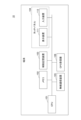
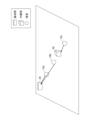
- Fig. 1 is a diagram showing an example of the configuration of a wireless communication system in a first embodiment.
- Fig. 1 shows one base station 20, one relay station 30, and multiple terminals 10 such as terminal 10a, terminal 10b, and terminal 10b (hereinafter, referred to as "terminal 10" when not distinguishing between them).
- the base station 20 is a communication device that functions as a base station that accommodates the terminal 10 in a mobile communication network via radio waves.
- the relay station 30 is a communication device (repeater, relay communication terminal, etc.) that functions as a relay station that accommodates the terminal 10 in a mobile communication network via the base station 20 by relaying the radio waves of the base station 20.
- the terminal 10 is, for example, a communication terminal such as a smartphone, a tablet terminal, or a PC (Personal Computer).
- FIG. 1 shows an example in which there is one relay station subordinate to the base station 20, there may be multiple relay stations subordinate to the base station 20.
- all three terminals 10 can receive radio waves from both the base station 20 and the relay station 30.
- the received power at terminal 10a is greater from the base station 20, while the received power at terminals 10b and 10c is greater from the relay station 30.
- terminal 10c may only be able to receive radio waves from the relay station 30.
- FIG. 2 is a diagram showing an example of the hardware configuration of the terminal 10 in the first embodiment.
- the terminal 10 has a CPU 101, a memory 102, an auxiliary storage device 103, a touch panel 104, a wireless communication device 105, a GPS receiver 106, etc.
- the auxiliary storage device 103 stores programs and the like installed on the terminal 10.
- the memory 102 reads out the program from the auxiliary storage device 103 and stores it.
- the CPU 101 realizes functions related to the terminal 10 according to the program stored in the memory 102.
- the touch panel 104 is an electronic component that has both an input function and a display function, and displays information and accepts input from the user.
- the touch panel 104 includes a display device 111 and an input device 112.
- the display device 111 is a liquid crystal display or the like, and performs the display function of the touch panel 104.
- the input device 112 is an electronic component including a sensor that detects the contact of a contacting object with the display device 111.
- the method for detecting the contact of a contacting object may be any known method such as an electrostatic method, a resistive film method, or an optical method.
- a contacting object refers to an object that comes into contact with the contact surface (surface) of the touch panel 104. Examples of such objects include a user's finger and a dedicated or general pen.
- the wireless communication device 105 is an electronic component such as an antenna required for communication in a wireless LAN (Local Area Network) or a mobile communication network.
- the GPS receiver 106 receives radio waves from a GPS (Global Positioning System) satellite.
- the base station 20 and relay station 30 may also have a CPU, memory, and auxiliary storage device, and may have functions realized by processes that a program causes the CPU to execute.
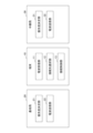
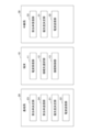
- FIG. 3 is a diagram showing an example of the functional configuration of a wireless communication system in the first embodiment.
- the base station 20 has a priority determination unit 21 and a radio wave transmission unit 22.
- Each of these units is realized by a process executed by the CPU of the base station 20 by a program installed in the base station 20. Alternatively, each of these units may be realized by hardware.
- the terminal 10 has a radio wave receiving unit 11, a connection destination selecting unit 12, and a connection control unit 13. Each of these units is realized by a process executed by the CPU 101 of one or more programs installed in the terminal 10. Alternatively, each of these units may be realized by hardware.
- the relay station 30 has a priority determination unit 31 and a radio wave transmission unit 32. Each of these units is realized by a process executed by the CPU of the relay station 30 by a program installed in the relay station 30. Alternatively, each of these units may be realized by hardware.
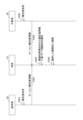
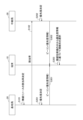
- Figure 4 is a sequence diagram for explaining an example of the processing procedure executed by the wireless communication system in the first embodiment.
- step S201 the priority determination unit 21 of the base station 20 determines the priority of the base station based on the attributes of the base station.
- the priority is an example of information other than the received power that the terminal 10 uses to select a connection destination.
- step S202 the priority determination unit 21 of the relay station 30 determines the priority of the own station based on the attributes of the own station.
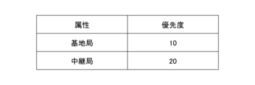
- FIG. 5 is a diagram for explaining a method of determining priority in the first embodiment.
- priority is determined according to the attribute (whether it is a base station or a relay station).
- Information (table) such as that shown in FIG. 5 may be preset for each of the base station 20 and relay station 30, or a priority for a "base station” may be preset for the base station 20, and a priority for a "relay station” may be preset for the relay station 30.
- priority means a priority order. Therefore, the smaller the priority value, the higher the priority.
- step S201 the priority determination unit 21 determines that the priority of the local station is "10.”
- step S202 the priority determination unit 31 determines that the priority of the local station is "20.”
- the radio wave transmitting unit 22 of the base station 20 notifies each terminal 10 of the determined priority by transmitting a radio wave (e.g., a beacon signal, etc.) including the priority (S301).
- a radio wave e.g., a beacon signal, etc.
- the radio wave transmitting unit 32 of the base station 20 notifies each terminal 10 of the determined priority by transmitting a radio wave (e.g., a beacon signal, etc.) including the priority (S302).
- a radio wave e.g., a beacon signal, etc.
- connection destination selecting unit 12 selects the connection destination candidate with the highest priority (the smallest priority value) from among the sources of the received radio waves that satisfy a predetermined condition (hereinafter referred to as "connection destination candidates") as the connection destination (S303).
- the predetermined condition may be, for example, a condition regarding the radio wave reception status (for example, the received power is equal to or greater than a threshold).
- connection control unit 13 controls the wireless connection to the selected connection destination candidate (base station 20 or relay station 30) (S304).
- connection destinations of each terminal 10 are as follows:
- Figure 6 is a diagram showing an example of the connection destinations of each terminal 10 in the first embodiment.
- each terminal 10 the connection destination of each terminal 10 is indicated by an arrow starting from each terminal 10.
- both base station 20 and relay station 30 are connection destination candidates, but since base station 20 has a higher priority, terminals 10a and 10b connect to (are accommodated by) base station 20.
- terminal 10c the only connection destination candidate is relay station 30, so terminal 10c connects to (is accommodated by) relay station 30.
- the terminal 10b will connect to the relay station 30.
- the terminal 10b can be connected to the base station 20 directly, not via the relay station 30.
- the first embodiment it is possible to improve the efficiency of the connection relationship between the base station and relay station and the terminal. As a result, for example, it is possible to improve the utilization efficiency of wireless resources and improve the communication quality of the entire wireless system.
- the radio waves transmitted in steps S301 and S302 may contain information other than the priority.
- information indicating the attributes of the source of the radio waves may be included in the radio waves instead of the priority.
- the connection destination selection unit 12 of the terminal 10 may determine that a "base station” has a higher priority than a "relay station” and select a connection destination.
- the radio waves may include location information (e.g., latitude and longitude) of the base station 20 or relay station 30 instead of the priority.
- the connection destination selection unit 12 of the terminal 10 may prioritize connection to one of the base stations 20 and relay stations 30 based on the positional relationship between the terminal 10 and the base station 20 and relay station 30.
- the location of the terminal 10 can be identified based on the radio waves received by the GPS receiver 106.
- the method of determining the priority by the priority determination unit 21 and the priority determination unit 31 in step S201 or S202 in FIG. 4 is different.
- FIG. 7 is a diagram for explaining a method of determining priority in the second embodiment.
- FIG. 7 shows that priority changes according to attributes and communication congestion levels, and shows specific examples of priority according to each attribute and communication congestion level.
- Communication congestion level can be rephrased as the usage status of wireless resources, for example, channel utilization rate (%). If the priority according to the attribute is A and the numerical value according to the communication congestion level is B, the priority of the base station 20 and relay station 30 is determined by A x B.
- steps S201 and S202 may be executed at multiple times, such as periodically or at some other time (for example, when the degree of communication congestion has changed by a predetermined value or more).
- the second embodiment it is possible to obtain the same effect as the first embodiment. Furthermore, according to the second embodiment, it is possible to dynamically control the connection destination of the terminal 10 depending on the communication congestion state at the base station 20 or the relay station 30.
- FIG. 8 is a diagram showing an example of the functional configuration of a wireless communication system in the third embodiment.
- parts that are the same as or correspond to those in FIG. 3 are given the same reference numerals.
- the base station 20 further includes an allocation rate determination unit 23 and an allocation rate transmission unit 24.
- Each of these units is realized by a process executed by the CPU of the base station 20 by a program installed in the base station 20. Alternatively, each of these units may be realized by hardware.
- the relay station 30 further includes an allocation rate receiving unit 33.
- the allocation rate receiving unit 33 is realized by a process executed by the CPU of the relay station 30 by a program installed in the relay station 30. Alternatively, each of these units may be realized by hardware.
- FIG. 9 is a sequence diagram for explaining an example of a processing procedure executed by a wireless communication system in the third embodiment.
- steps that are the same as or correspond to those in FIG. 4 are given the same reference numerals, and their explanation will be omitted as appropriate.
- steps S101 and S102 are executed before steps S201 and S202.
- step S201 may be executed before steps S101 and S102.
- the allocation rate determination unit 23 of the base station 20 determines an allocation rate for the terminal 10 (hereinafter referred to as the "allocation rate for terminal") and an allocation rate for the relay station 30 (hereinafter referred to as the "allocation rate for relay station") for the wireless resources (e.g., communication time, etc.) of the base station itself.
- the allocation rate for terminal is the allocation rate of wireless resources used by the base station 20 for communication with the terminal 10.
- the allocation rate transmission unit 24 transmits the relay station allocation rate for the relay station 30 to the relay station 30 (S102).
- the allocation rate reception unit 33 of the relay station 30 receives the relay station allocation rate.
- the priority is determined based on the allocation rate for the terminal or the allocation rate for the relay station.
- FIG. 10 is a diagram for explaining the method of determining priority in the third embodiment.
- FIG. 10 shows that priority changes depending on attributes, communication congestion, and terminal allocation rate or relay station allocation rate, and shows specific examples of priority depending on these. If the priority depending on the attribute is A, the numerical value depending on the communication congestion is B, the terminal allocation rate is C, and the relay station allocation rate is D, the priority of the base station 20 is determined by A x B x C, and the priority of the relay station 30 is determined by A x B x D.
- steps S101 to S202 may be executed at multiple times, such as periodically or at some other time (for example, when the degree of communication congestion has changed by a predetermined value or more).
- the degree of communication congestion (B) may not be used in calculating the priority.
- the priority of the base station 20 may be determined by A x C
- the priority of the relay station 30 may be determined by A x D.
- the second embodiment it is possible to obtain the same effect as the first embodiment. Furthermore, according to the second embodiment, it is possible to dynamically control the connection destination of the terminal 10 according to the allocation of radio resources of the base station 20.
- the radio wave transmitting unit 22 of the base station 20 and the radio wave transmitting unit 32 of the relay station 30 may include, together with the priority, a parameter (e.g., a threshold value for received power) that constitutes a predetermined condition for the terminal 10 to determine a connection destination candidate in the radio waves transmitted in step S201 or S202.
- a parameter e.g., a threshold value for received power
- the value of the parameter may be different between the base station 20 and the relay station 30.
Landscapes
- Engineering & Computer Science (AREA)
- Computer Networks & Wireless Communication (AREA)
- Signal Processing (AREA)
- Computer Security & Cryptography (AREA)
- Mobile Radio Communication Systems (AREA)
Abstract
通信端末は、基地局及び中継局のそれぞれから送信される電波を受信するように構成されている電波受信部と、前記電波に含まれている、受信電力以外の情報に基づいて、前記電波の送信元の中から接続先を選択するように構成されている接続先選択部と、を有することで、基地局及び中継局と端末の接続関係を効率化する。
Description
本発明は、通信端末、通信装置及び通信方法に関する。
無線通信システムにおける高周波数帯の利用拡大に伴い、減衰や遮蔽の影響が大きくなる中、中継局(リピータ・中継通信端末等)を活用した無線置局設計に関する技術検討が行われている。
例えば、非特許文献1では、任意の環境において一定数の中継局を置局可能な場合に適切な配置によるユーザの通信品質改善のための置局設計方法が提案されている。非特許文献2では、中継通信端末の位置やアンテナの向きを適切に決定する手法が提案されている。
米田他、"ミリ波セルラシステムにおけるカバレッジ拡張とブロッキングを考慮したAF中継局置局設計に関する検討"、信学技報, vol. 121, no. 391, RCS2021-290, pp. 189-194, 2022年3月
藤尾他、"移動中継通信システムにおける中継通信端末配置に関する位置検討"、電子情報通信学会総合大会, B-5-25, 2022年3月
従来技術では、中継局の置局設計は検討されているものの、端末が基地局と中継局の両方で収容可能な場合に、当該端末に対する収容制御は検討されていない。基本的に、端末は、基地局と中継局の両方に接続可能な場合、受信電力が大きい方に接続する。基地局にも接続可能な端末が中継局に接続してしまうことで、中継局の無線リソースが無駄に消費されてしまう可能性が有る。
本発明は、上記の点に鑑みてなされたものであって、基地局及び中継局と端末の接続関係を効率化することを目的とする。
そこで上記課題を解決するため、通信端末は、基地局及び中継局のそれぞれから送信される電波を受信するように構成されている電波受信部と、前記電波に含まれている、受信電力以外の情報に基づいて、前記電波の送信元の中から接続先を選択するように構成されている接続先選択部と、を有する。
基地局及び中継局と端末の接続関係を効率化することできる。
以下、図面に基づいて本発明の実施の形態を説明する。図1は、第1の実施の形態における無線通信システムの構成例を示す図である。図1には、1つの基地局20、1つの中継局30、及び端末10a、端末10b及び端末10b(以下、それぞれを区別しない場合「端末10」という。)等の複数の端末10が示されている。基地局20は、電波を介して端末10を移動体通信網に収容する基地局として機能する通信装置である。中継局30は、基地局20の電波を中継することで、基地局20を介して端末10を移動体通信網へ収容する中継局として機能する通信装置(リピータ・中継通信端末等)である。端末10は、例えば、スマートフォン、タブレット端末又はPC(Personal Computer)等の通信端末である。
なお、図1では、基地局20の配下の中継局が1つある例が示されているが、基地局20の配下の中継局は複数であってもよい。
図1において、3つの端末10は、いずれも基地局20及び中継局30の双方からの電波を受信可能である。但し、端末10aにおける受信電力は基地局20の方が大きく、端末10b及び端末10cにおける受信電力は中継局30の方が大きい。又は、端末10cは、中継局30からの電波のみを受信可能であってもよい。
図2は、第1の実施の形態における端末10のハードウェア構成例を示す図である。図2において、端末10は、CPU101、メモリ102、補助記憶装置103、タッチパネル104、無線通信装置105及びGPS受信機106等を有する。
補助記憶装置103は、端末10にインストールされたプログラム等を記憶する。メモリ102は、プログラムの起動指示があった場合に、補助記憶装置103からプログラムを読み出して記憶する。CPU101は、メモリ102に記憶されたプログラムに従って端末10に係る機能を実現する。
タッチパネル104は、入力機能と表示機能との双方を備えた電子部品であり、情報の表示や、ユーザからの入力の受け付け等を行う。タッチパネル104は、表示装置111及び入力装置112等を含む。
表示装置111は、液晶ディスプレイ等であり、タッチパネル104の表示機能を担う。入力装置112は、表示装置111に対する接触物の接触を検出するセンサを含む電子部品である。接触物の接触の検出方式は、静電方式、抵抗膜方式、又は光学方式等、公知の方式のいずれであってもよい。なお、接触物とは、タッチパネル104の接触面(表面)に接触する物体をいう。斯かる物体の一例として、ユーザの指や専用又は一般のペン等が挙げられる。
無線通信装置105は、無線LAN(Local Area Network)又は移動体通信網等における通信を行うために必要とされるアンテナ等の電子部品である。GPS受信機106は、GPS(Global Positioning System)衛星からの電波を受信する。
なお、基地局20及び中継局30も、CPU、メモリ及び補助記憶装置を有し、プログラムがCPUに実行させる処理によって実現される機能を有してもよい。
図3は、第1の実施の形態における無線通信システムの機能構成例を示す図である。図3において、基地局20は、優先度決定部21及び電波送信部22を有する。これら各部は、基地局20にインストールされたプログラムが基地局20のCPUに実行させる処理により実現される。又は、これら各部はハードウェアによって実現されてもよい。
端末10は、電波受信部11、接続先選択部12及び接続制御部13を有する。これら各部は、端末10にインストールされた1以上のプログラムが、CPU101に実行させる処理により実現される。又は、これら各部はハードウェアによって実現されてもよい。
中継局30は、優先度決定部31及び電波送信部32を有する。これら各部は、中継局30にインストールされたプログラムが中継局30のCPUに実行させる処理により実現される。又は、これら各部はハードウェアによって実現されてもよい。
以下、第1の実施の形態において実行される処理手順について説明する。図4は、第1の実施の形態における無線通信システムが実行する処理手順の一例を説明するためのシーケンス図である。
ステップS201において、基地局20の優先度決定部21は、自局の属性に基づいて自局の優先度を決定する。優先度とは、端末10が接続先を選択するために利用する、受信電力以外の情報の一例である。
一方、ステップS202において、中継局30の優先度決定部21は、自局の属性に基づいて自局の優先度を決定する。
図5は、第1の実施の形態における優先度の決定方法を説明するための図である。図5に示されるように、第1の実施の形態では、属性(基地局であるか中継局であるか)に応じて優先度が決まる。基地局20及び中継局30のそれぞれに、図5に示されるような情報(表)が予め設定されてもよいし、基地局20には「基地局」に対する優先度が予め設定され、中継局30には「中継局」に対する優先度が予め設定されてもよい。なお、本実施の形態において、優先度は優先順位を意味する。したがって、優先度の値が小さいほど優先度は高い。
したがって、ステップS201において、優先度決定部21は、自局の優先度が「10」であることを決定する。ステップS202において、優先度決定部31は、自局の優先度が「20」であることを決定する。
続いて、基地局20の電波送信部22は、決定した優先度を含む電波(例えば、ビーコン信号等)を送信することで、当該優先度を各端末10に報知する(S301)。
同様に、基地局20の電波送信部32は、決定した優先度を含む電波(例えば、ビーコン信号等)を送信することで、当該優先度を各端末10に報知する(S302)。
各端末10において、電波受信部11がそれぞれの電波(優先度を含む電波)を受信すると、接続先選択部12は、受信した電波の送信元のうち、所定の条件を満たす送信元(以下、「接続先候補」という。)の中から、優先度が最も高い(優先度の値が最小である)接続先候補を接続先として選択する(S303)。所定の条件とは、例えば、電波の受信状況に対する条件(例えば、受信電力が閾値以上であること)であってもよい。
続いて、接続制御部13は、選択された接続先候補(基地局20又は中継局30)への無線接続を制御する(S304)。
その結果、例えば、各端末10の接続先は以下のようになる。図6は、第1の実施の形態における各端末10の接続先の一例を示す図である。
図6では、各端末10を始点とする矢印によって各端末10の接続先が示されている。端末10a及び端末10bにとって、基地局20及び中継局30の双方は接続先候補になるところ、基地局20の方が優先度が高いため、端末10a及び端末10bは基地局20に接続する(収容される)。一方、端末10cにとって、接続先候補は中継局30だけであるため、端末10cは中継局30に接続する(収容される)。
例えば、受信電力のみに基づいて接続先が選択される場合、端末10bは、中継局30に接続することになる。一方、第1の形態によれば、端末10bを、中継局30を介してではなく直接的に基地局20に接続させることができる。
上述したように、第1の実施の形態によれば、基地局及び中継局と端末の接続関係を効率化することができる。その結果、例えば、無線リソースの利用効率を改善し、無線システム全体の通信品質を改善することができる。
なお、上記では、ステップS301及びS302において送信される電波に含まれる情報が優先度である例を示したが、優先度以外の情報が当該電波に含まれてもよい。例えば、当該電波の送信元の属性(「基地局」であるのか「中継局」であるのか)を示す情報が優先度の代わりに当該電波に含まれるようにしてもよい。この場合、端末10の接続先選択部12は、「基地局」を「中継局」よりも優先度が高いと判断して接続先を選択するようにしてもよい。
又は、当該電波には、基地局20又は中継局30の位置情報(例えば、緯度及び経度)が優先度の代わりに含まれるようにしてもよい。この場合、端末10の接続先選択部12は、当該端末10と基地局20及び中継局30との位置関係に基づいて、いずれか一方への接続を優先させるようにしてもよい。当該端末10の位置は、GPS受信機106が受信する電波に基づいて特定可能である。
次に、第2の実施の形態について説明する。第2の実施の形態では第1の実施の形態と異なる点について説明する。第2の実施の形態において特に言及されない点については、第1の実施の形態と同様でもよい。
第2の実施の形態では、図4のステップS201又はS202における、優先度決定部21及び優先度決定部31による優先度の決定方法が異なる。
図7は、第2の実施の形態における優先度の決定方法を説明するための図である。図7には、属性及び通信混雑度に応じて優先度が変化すること、及び各属性及び通信混雑度に応じた優先度の具体例が示されている。通信混雑度は、無線リソースの利用状況と言い換えてもよく、例えば、チャネル利用率(%)である。属性に応じた優先度をA、通信混雑度に応じた数値をBとした場合、基地局20及び中継局30の優先度は、A×Bによって決まる。
したがって、優先度決定部21は、ステップS201において、「基地局」に対応する優先度(=10)に対して自局の通信混雑度に応じた数値(B)を乗じることで自局の優先度を決定する。同様に、優先度決定部31は、ステップS202において、「中継局」に対応する優先度(=20)に対して自局の通信混雑度に応じた数値(B)を乗じることで自局の優先度を決定する。
以降は、第1の実施の形態と同様でよい。
なお、通信混雑度は刻々と変化する。したがって、ステップS201及びS202は、定期的なタイミング又はなんらかのタイミング(例えば、通信混雑度が所定値以上変化したタイミング等)等、複数のタイミングで実行されればよい。
上述したように、第2の実施の形態によれば、第1の実施の形態と同様の効果を得ることができる。また、第2の実施の形態によれば、基地局20又は中継局30における通信の混雑状況に応じて端末10の接続先を動的に制御することができる。
次に、第3の実施の形態について説明する。第3の実施の形態では第1の実施の形態と異なる点について説明する。第3の実施の形態において特に言及されない点については、第1の実施の形態と同様でもよい。
図8は、第3の実施の形態における無線通信システムの機能構成例を示す図である。図8中、図3と同一部分又は対応する部分には同一符号を付している。
図8において、基地局20は、更に、割当率決定部23及び割当率送信部24を有する。これら各部は、基地局20にインストールされたプログラムが基地局20のCPUに実行させる処理により実現される。又は、これら各部はハードウェアによって実現されてもよい。
中継局30は、更に、割当率受信部33を有する。割当率受信部33は、中継局30にインストールされたプログラムが中継局30のCPUに実行させる処理により実現される。又は、これら各部はハードウェアによって実現されてもよい。
図9は、第3の実施の形態における無線通信システムが実行する処理手順の一例を説明するためのシーケンス図である。図9中、図4と同一ステップ又は対応するステップには同一符号を付し、その説明は適宜省略する。
図9では、ステップS201及びS202の前に、ステップS101及びS102が実行される。但し、ステップS201は、ステップS101及びS102の前に実行されてもよい。
ステップS101において、基地局20の割当率決定部23は、自局の無線リソース(例えば、通信時間等)について、端末10に対する割当率(以下、「端末向け割当率」という。)と、中継局30に対する割当率(以下、「中継局向け割当率」という。)とを決定する。端末向け割当率は、基地局20が端末10との通信に利用する無線リソースの割当率である。中継局向け割当率は、基地局20が中継局30との通信に利用する無線リソースの割当率である。例えば、端末向け割当率:中継局向け割当率=70:30等が決定される。なお、基地局20が複数の中継局30を配下に有する場合、中継局向け割当率は、中継局30ごとに決められる。なお、割当率の決定は、任意の方法で行われればよい。例えば、割当率は予め設定されてもよい。
続いて、割当率送信部24は、中継局30に対して、当該中継局30に対する中継局向け割当率を送信する(S102)。当該中継局30の割当率受信部33は、当該中継局向け割当率を受信する。
ステップS201及びS202では、端末向け割当率又は中継局向け割当率に基づいて優先度が決定される。
図10は、第3の実施の形態における優先度の決定方法を説明するための図である。図10には、属性、通信混雑度、及び端末向け割当率若しくは中継局向け割当率に応じて優先度が変化すること、及びこれらに応じた優先度の具体例が示されている。属性に応じた優先度をA、通信混雑度に応じた数値をB、端末向け割当率をC、中継局向け割当率をDとした場合、基地局20の優先度は、A×B×Cによって決まり、中継局30の優先度は、A×B×Dによって決まる。
したがって、優先度決定部21は、ステップS201において、基地局に対応する優先度(=10)に対して自局の通信混雑度に応じた数値(B)及び端末向け割当率(C)を乗じることで自局の優先度を決定する。一方、優先度決定部31は、ステップS202において、基地局に対応する優先度(=20)に対して自局の通信混雑度に応じた数値(B)及びステップS102において受信した割当率(D)を乗じることで自局の優先度を決定する。
以降は、第1の実施の形態と同様でよい。
なお、割当率を通信状況に応じて動的に変化させる場合、ステップS101~202は、定期的なタイミング又はなんらかのタイミング(例えば、通信混雑度が所定値以上変化したタイミング等)等、複数のタイミングで実行されればよい。
また、優先度の計算に通信混雑度(B)が使用されないようにしてもよい。例えば、割当率が通信混雑度を考慮して計算される場合は、基地局20の優先度はA×Cによって決まり、中継局30の優先度はA×Dによって決まるようにしてもよい。
上述したように、第2の実施の形態によれば、第1の実施の形態と同様の効果を得ることができる。また、第2の実施の形態によれば、基地局20の無線リソースの割当に応じて端末10の接続先を動的に制御することができる。
なお、上記各実施の形態において、基地局20の電波送信部22及び中継局30の電波送信部32は、ステップS201又はS202において送信する電波に、端末10が接続先候補を決めるための所定の条計を構成するパラメータ(例えば、受信電力に対する閾値)を優先度と共に含めてもよい。この場合、基地局20と中継局30とで当該パラメータの値は異なってもよい。
以上、本発明の実施の形態について詳述したが、本発明は斯かる特定の実施形態に限定されるものではなく、請求の範囲に記載された本発明の要旨の範囲内において、種々の変形・変更が可能である。
10 端末
11 電波受信部
12 接続先選択部
13 接続制御部
20 基地局
21 優先度決定部
22 電波送信部
23 割当率決定部
24 割当率送信部
30 中継局
31 優先度決定部
32 電波送信部
33 割当率受信部
101 CPU
102 メモリ
103 補助記憶装置
104 タッチパネル
105 無線通信装置
106 GPS受信機
11 電波受信部
12 接続先選択部
13 接続制御部
20 基地局
21 優先度決定部
22 電波送信部
23 割当率決定部
24 割当率送信部
30 中継局
31 優先度決定部
32 電波送信部
33 割当率受信部
101 CPU
102 メモリ
103 補助記憶装置
104 タッチパネル
105 無線通信装置
106 GPS受信機
Claims (8)
- 基地局及び中継局のそれぞれから送信される電波を受信するように構成されている電波受信部と、
前記電波に含まれている、受信電力以外の情報に基づいて、前記電波の送信元の中から接続先を選択するように構成されている接続先選択部と、
を有することを特徴とする通信端末。 - 前記情報は、前記電波の送信元が基地局であるか中継局であるかに応じて異なる、
ことを特徴とする請求項1記載の通信端末。 - 前記情報は、優先度である、
ことを特徴とする請求項1又は2記載の通信端末。 - 前記接続先選択部は、受信電力が閾値以上である前記電波の送信元の中から接続先を選択する、
ことを特徴とする請求項1記載の通信端末。 - 基地局又は中継局として機能する通信装置であって、
当該通信装置が基地局であるか中継局であるかに応じて異なる情報を含む電波を送信するように構成されている電波送信部を有し、
前記情報は、前記電波を受信した端末が接続先を選択するために用いられる、
ことを特徴とする通信装置。 - 前記情報は、更に、当該通信装置の無線リソースの利用状況に応じて異なる、
ことを特徴とする請求項5記載の通信装置。 - 前記情報は、更に、前記基地局の無線リソースについて、端末への割当率又は前記中継局への割当率に基づいて異なる、
ことを特徴とする請求項5又は6記載の通信装置。 - 通信端末が、
基地局及び中継局のそれぞれから送信される電波を受信する電波受信手順と、
前記電波に含まれている、受信電力以外の情報に基づいて、前記電波の送信元の中から接続先を選択する接続先選択手順と、
を実行することを特徴とする通信方法。
Priority Applications (2)
| Application Number | Priority Date | Filing Date | Title |
|---|---|---|---|
| PCT/JP2023/021025 WO2024252524A1 (ja) | 2023-06-06 | 2023-06-06 | 通信端末、通信装置及び通信方法 |
| JP2025525496A JPWO2024252524A1 (ja) | 2023-06-06 | 2023-06-06 |
Applications Claiming Priority (1)
| Application Number | Priority Date | Filing Date | Title |
|---|---|---|---|
| PCT/JP2023/021025 WO2024252524A1 (ja) | 2023-06-06 | 2023-06-06 | 通信端末、通信装置及び通信方法 |
Publications (1)
| Publication Number | Publication Date |
|---|---|
| WO2024252524A1 true WO2024252524A1 (ja) | 2024-12-12 |
Family
ID=93795461
Family Applications (1)
| Application Number | Title | Priority Date | Filing Date |
|---|---|---|---|
| PCT/JP2023/021025 Ceased WO2024252524A1 (ja) | 2023-06-06 | 2023-06-06 | 通信端末、通信装置及び通信方法 |
Country Status (2)
| Country | Link |
|---|---|
| JP (1) | JPWO2024252524A1 (ja) |
| WO (1) | WO2024252524A1 (ja) |
Citations (4)
| Publication number | Priority date | Publication date | Assignee | Title |
|---|---|---|---|---|
| WO2011121714A1 (ja) * | 2010-03-30 | 2011-10-06 | 富士通株式会社 | 移動通信システム、無線中継装置、移動通信装置および無線通信方法 |
| JP2013012818A (ja) * | 2011-06-28 | 2013-01-17 | Kyocera Corp | 無線通信システム、無線中継装置および通信制御方法 |
| WO2015129356A1 (ja) * | 2014-02-28 | 2015-09-03 | 株式会社日立国際電気 | 無線通信端末 |
| JP2022105306A (ja) * | 2020-12-31 | 2022-07-13 | スターライト テクノロジーズ リミテッド | オープン無線アクセスネットワーク(o-ran)環境でハンドオーバ(ho)手順を開始するための方法及び装置 |
-
2023
- 2023-06-06 WO PCT/JP2023/021025 patent/WO2024252524A1/ja not_active Ceased
- 2023-06-06 JP JP2025525496A patent/JPWO2024252524A1/ja active Pending
Patent Citations (4)
| Publication number | Priority date | Publication date | Assignee | Title |
|---|---|---|---|---|
| WO2011121714A1 (ja) * | 2010-03-30 | 2011-10-06 | 富士通株式会社 | 移動通信システム、無線中継装置、移動通信装置および無線通信方法 |
| JP2013012818A (ja) * | 2011-06-28 | 2013-01-17 | Kyocera Corp | 無線通信システム、無線中継装置および通信制御方法 |
| WO2015129356A1 (ja) * | 2014-02-28 | 2015-09-03 | 株式会社日立国際電気 | 無線通信端末 |
| JP2022105306A (ja) * | 2020-12-31 | 2022-07-13 | スターライト テクノロジーズ リミテッド | オープン無線アクセスネットワーク(o-ran)環境でハンドオーバ(ho)手順を開始するための方法及び装置 |
Also Published As
| Publication number | Publication date |
|---|---|
| JPWO2024252524A1 (ja) | 2024-12-12 |
Similar Documents
| Publication | Publication Date | Title |
|---|---|---|
| JP7726947B2 (ja) | 伝送指示方法及び装置 | |
| US9754486B2 (en) | Safety information transmission method and safety information transmission system | |
| US9965239B2 (en) | Linked display system, linked display method and program | |
| US8503927B2 (en) | Methods, systems, and computer-readable media for utilizing a repeating function to improve quality of service | |
| JP2010278825A (ja) | 無線通信装置、無線通信システムおよび無線通信方法 | |
| CN104866265A (zh) | 多媒体文件的显示方法和装置 | |
| US20180041945A1 (en) | Radio communication terminal and frequency assignment method | |
| CN111565064A (zh) | 卫星位置信息传输方法、装置、系统及存储介质 | |
| US8571788B2 (en) | Apparatus and method for generating sketch map information in portable terminal | |
| US10165510B2 (en) | Wireless communication device, wireless communication method, and wireless communication system | |
| WO2022024196A1 (ja) | 通信システム、接続先制御方法、制御装置、及びプログラム | |
| US10771373B2 (en) | Ad hoc network route construction system, node, and center node | |
| CN110139370B (zh) | 信息指示的方法、通信装置和通信系统 | |
| US11770754B2 (en) | Network management apparatus, network management method, and storage medium for network comprising a plurality of vehicles and plurality of mobile terminals | |
| JP5705030B2 (ja) | 通信システム | |
| US11916653B2 (en) | Optimizing signal transmission handoff to low earth orbit (LEO) satellites | |
| US10305779B2 (en) | Ad hoc network route construction system, node, and center node | |
| AU2024251384A1 (en) | Low earth orbit satellite communication using device diversity reception and transmission | |
| KR100713647B1 (ko) | 무선 통신 단말기를 이용한 동시 통역 시스템 | |
| EP4175343A1 (en) | Electronic device, wireless communication method and non-transitory computer-readable storage medium | |
| CN105959301B (zh) | 一种多媒体通话的优化方法及其优化系统 | |
| JP6150920B1 (ja) | 携帯端末、制御方法及び制御プログラム | |
| JP2007089018A (ja) | 無線通信端末のナビゲーションシステムおよびそのナビゲーション方法 | |
| KR20180040949A (ko) | 중계기를 이용한 콘텐츠 제공 시스템 및 콘텐츠 제공방법 | |
| US20160014563A1 (en) | Apparatus, system and method of selecting location providers |
Legal Events
| Date | Code | Title | Description |
|---|---|---|---|
| 121 | Ep: the epo has been informed by wipo that ep was designated in this application |
Ref document number: 23940629 Country of ref document: EP Kind code of ref document: A1 |
|
| ENP | Entry into the national phase |
Ref document number: 2025525496 Country of ref document: JP Kind code of ref document: A |
|
| WWE | Wipo information: entry into national phase |
Ref document number: 2025525496 Country of ref document: JP |
|
| NENP | Non-entry into the national phase |
Ref country code: DE |