WO2024252495A1 - 手形状識別装置、手形状識別方法、および手形状識別プログラム - Google Patents
手形状識別装置、手形状識別方法、および手形状識別プログラム Download PDFInfo
- Publication number
- WO2024252495A1 WO2024252495A1 PCT/JP2023/020874 JP2023020874W WO2024252495A1 WO 2024252495 A1 WO2024252495 A1 WO 2024252495A1 JP 2023020874 W JP2023020874 W JP 2023020874W WO 2024252495 A1 WO2024252495 A1 WO 2024252495A1
- Authority
- WO
- WIPO (PCT)
- Prior art keywords
- unit
- hand
- signal
- vibration
- generating
- Prior art date
- Legal status (The legal status is an assumption and is not a legal conclusion. Google has not performed a legal analysis and makes no representation as to the accuracy of the status listed.)
- Ceased
Links
Images





Classifications
-
- G—PHYSICS
- G06—COMPUTING OR CALCULATING; COUNTING
- G06F—ELECTRIC DIGITAL DATA PROCESSING
- G06F3/00—Input arrangements for transferring data to be processed into a form capable of being handled by the computer; Output arrangements for transferring data from processing unit to output unit, e.g. interface arrangements
- G06F3/01—Input arrangements or combined input and output arrangements for interaction between user and computer
Definitions
- the present invention relates to a hand shape recognition device, a hand shape recognition method, and a hand shape recognition program.
- Non-Patent Document 1 There is a method that uses a pair of sensors attached to the back of the hand with double-sided tape, irradiates an acoustic signal from one sensor and acquires it with the other sensor, and distinguishes the hand shape based on the displacement of the acquired signal.
- Non-Patent Document 1 does not impede finger movement because the sensor is attached to the back of the hand, the sensor must be attached and used each time the device is worn, which means that there is an error in the attachment position each time the device is worn, making it difficult for the user to wear the device conveniently.
- the present invention was made in light of the above-mentioned circumstances, and its main objective is to provide a hand shape identification device that can identify the hand shape without constricting the user's hand, does not hinder the user's hand movements, and allows the user to attach the sensor in the same position without intending to do so.
- the hand shape identification device has a measurement wearing body, a signal generating/processing unit, a hand shape estimating unit, and an identifying unit.
- the measurement wearing body includes a vibration generating/acquiring unit capable of generating and acquiring vibrations, a wearing body that can be positioned to cover the back of the hand to be measured, and a finger wearing body through which the fingers of the hand are passed, allowing the vibration generating/acquiring unit fixed to the wearing body to be attached to the back of the hand to be measured with good positional reproducibility.
- the signal generating/processing unit generates a vibration generating signal that generates vibration in the vibration generating/acquiring unit and transmits the vibration generating signal to the vibration generating/acquiring unit, while also receiving and processing a vibration signal representing the vibration that has passed through the hand and acquired by the vibration generating/acquiring unit, and outputting a processed signal.
- the hand shape estimating unit generates a learning model that estimates the hand shape using machine learning from the processed signal.
- the identifying unit identifies the hand shape using the learning model.
- the present invention provides a hand shape identification device that identifies the hand shape without constricting the user's hand, does not hinder the user's hand movement, and allows the user to attach the sensor in the same position without intending to do so.
- FIG. 1 is a diagram illustrating an example of the configuration of a hand shape identification device according to an embodiment.
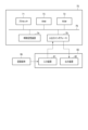
- FIG. 2 is a functional block diagram of the measurement wearer unit, the signal generating/measuring unit, the hand posture estimating unit, and the recognition unit in FIG.
- FIG. 3 is a diagram showing the hardware configuration of an information processing device that constitutes the signal generating and measuring unit, the hand posture estimating unit, and the identifying unit in FIG.
- FIG. 4 is a plan view of the piezoelectric element and the housing reinforcing portion.
- FIG. 5 is a perspective view of the housing reinforcing portion.
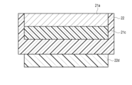
- FIG. 6 is a diagram showing a schematic cross-sectional structure of a piezoelectric element and a housing reinforcing portion.
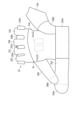
- FIG. 7 is a view of the measurement wearing body seen from the back of the hand.
- FIG. 8 is a view of the measurement wearable body part worn on the hand as viewed from the back of the hand.
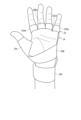
- FIG. 9 is a view of the measurement wearable body part worn on the hand, viewed from the palm side.
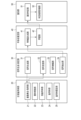
- FIG. 10 is a flowchart showing the flow of operations of the hand shape identification device.
- the hand shape identification device 10 includes a measurement wearer unit 20, a signal generating and measuring unit 30, a hand shape estimating unit 40, a recognition unit 50, and a database 60.
- a functional block diagram of the measurement wearer unit 20, the signal generating and measuring unit 30, the hand shape estimating unit 40, and the recognition unit 50 is shown in Fig. 2.
- the measurement wearable body 20 includes a vibration generating/acquiring unit 21 that applies vibrations to the hand of the subject to be measured and acquires the vibrations that have passed through the hand of the subject to be measured, and is an element for attaching the vibration generating/acquiring unit 21 to the hand of the subject to be measured with good positional reproducibility.
- the measurement wearing body unit 20 has five functional blocks: a vibration generating/acquiring unit 21, a housing reinforcement unit 22, a finger wearing body unit 23, a wearing body unit 24, and a wearing body fixing unit 25.
- the vibration generating/acquiring unit 21 is capable of generating and acquiring vibrations.
- the vibration generating/acquiring unit 21 has a pair of piezoelectric elements 21a capable of generating and acquiring any vibration.
- One of the first piezoelectric elements 21a receives a vibration generating signal from the signal generating/measuring unit 30, and generates vibrations having the same frequency characteristics as the vibration generating signal.
- the other, second piezoelectric element 21a acquires the vibrations generated from the first piezoelectric element 21a and passed through the hand of the measurement subject.
- the second piezoelectric element 21a outputs a vibration signal representing the acquired vibration.
- the piezoelectric element 21a is given as an example of an element that receives a vibration generation signal and generates vibration, and an element that acquires vibration and outputs a vibration signal, but any form is acceptable as long as it has such a function.
- the form of connection between the vibration generation and acquisition unit 21 and the signal generation and measurement unit 30 is acceptable as long as it has the function of transmitting and receiving electrical signals between the two.
- the housing reinforcement part 22 is shown in Figs. 4 to 6.
- the housing reinforcement part 22 is fixed to the piezoelectric element 21a.
- the housing reinforcement part 22 has a recess 22a capable of accommodating the piezoelectric element 21a, and the piezoelectric element 21a is fixed in the recess 22a by adhesive 21c.
- the housing reinforcement part 22 reinforces the strength of the fixed piezoelectric element 21a.
- the housing reinforcement part 22 is made of acrylic, a plastic part printed by 3D printing, etc.
- the housing reinforcement portion 22 also has a groove portion 22b extending from the recess portion 22a that houses the piezoelectric element 21a.
- the groove portion 22b is a stress dispersion structure for protecting the wiring 21b extending from the piezoelectric element 21a.
- the housing reinforcement part 22 has a plurality of through holes 22c for fixing to the wearing body part 24 by sewing. After the housing reinforcement part 22 is fixed to the wearing body part 24 by double-sided tape 22d, thread or the like is passed through the through holes 22c of the housing reinforcement part 22, and the housing reinforcement part 22 is firmly fixed to the wearing body part 24 by sewing.
- the finger wearing body part 23, the wearing body part 24, and the wearing body fixing part 25 are shown in Figures 7 to 9.
- the wearing body part 24 is an element that can be placed to cover the back of the hand.
- the wearing body part 24 has an armor body part 24a that is placed on the back of the hand, and a sleeve part 24b for passing the thumb through.
- the housing reinforcement part 22 containing the piezoelectric element 21a is fixed by sewing to the inside of the armor body part 24a, i.e., the side facing the back of the hand.
- the wearing body fixing part 25 is an element for fixing the wearing body part 24, which covers the back of the hand, to the hand.
- the wearing body fixing part 25 has a wrist belt 25A and a palm belt 25B.
- the wrist belt 25A is fixed to the wrist side end of the wearing body part 24 by sewing.
- the palm belt 25B is fixed to the little finger side of the finger side end of the wearing body part 24 by sewing.
- Both wrist belt 25A and palm belt 25B have hook and loop fasteners.
- the hook and loop fasteners are, for example, Velcro (registered trademark). Velcro is composed of a loop surface with many small loops and a hook surface with many hooks that engage with the loops.
- wrist belt 25A has hook surface portion 25Aa sewn to the tip and loop surface portion 25Ab sewn to the base end of wrist belt 25A.
- Palm belt 25B has hook surface portion 25Ba sewn to the tip and loop surface portion 25Bb sewn to the base end of sleeve portion 24b through which the thumb passes.
- the wrist belt 25A is an element that is wrapped around and fixed to the wrist, thereby fixing the wearing body 24 and the pair of piezoelectric elements 21a of the vibration generating/acquiring unit 21 in close contact with the back of the hand. Because the wrist belt 25A is wrapped around the wrist, it does not hinder the movement of the user's hand.
- the palm belt 25B is an element that is fixed diagonally across the lower part of the palm, thereby fixing the wearing body 24 and the pair of piezoelectric elements 21a in close contact with the back of the hand. Because the palm belt 25B passes under the lower part of the palm, it does little to hinder the movement of the user's hand.
- the finger wearing body 23 is an element that is wrapped around the fingers to secure the wearing body 24, which covers the back of the hand, to the hand.
- the finger wearing body 23 is fixed to the finger side end of the wearing body 24 by sewing.
- the finger wearing body 23 has finger wearing bodies 23A, 23B, 23C, and 23D for passing the index finger, middle finger, ring finger, and little finger.
- Each finger wearing body 23A, 23B, 23C, and 23D is an element that is positioned on the outside of each finger.
- Each finger wearing body 23A, 23B, 23C, and 23D has a finger belt 23Aa, 23Ba, 23Ca, and 23D fixed to it by sewing, respectively.
- Each finger belt 23Aa, 23Ba, 23Ca, 23Da is an element that is wrapped around each finger and fixed to secure each finger-wearing body 23A, 23B, 23C, 23D to each finger.
- Each finger belt 23Aa, 23Ba, 23Ca, 23D is basically the same structure as the wrist belt 25A and has a hook and loop fastener.
- the armor-wearing body 24a of the wearing body 24 has high flexibility. For this reason, the armor-wearing body 24a is made of a highly elastic material.
- the sleeve 24b of the wearing body 24 and the finger-wearing body parts 23A, 23B, 23C, and 23D of the finger-wearing body 23 have low flexibility. For this reason, the sleeve 24b and the finger-wearing body parts 23A, 23B, 23C, and 23D are made of a low-elasticity material.
- the armor body 24a makes it possible to fix the pair of piezoelectric elements 21a of the vibration generating/acquiring unit 21 in close contact with the back of the hand. Furthermore, the armor body 24a makes it possible to maintain close contact of the piezoelectric elements 21a with the back of the hand while suppressing the effects of finger movement.
- the signal generating and measuring unit 30 generates a vibration generating signal that causes the vibration generating and acquiring unit 21 to generate vibration, and transmits the vibration generating signal to the vibration generating and acquiring unit 21.
- the signal generating and measuring unit 30 also receives and processes the vibration signal representing the vibration that has passed through the hand and is acquired by the vibration generating and acquiring unit 21, and outputs a processed signal.
- the vibration generating signal is a signal having any frequency characteristic in the ultrasonic band.
- the signal generating and measuring unit 30 is composed of an information processing device such as a personal computer.
- the signal generating and measuring unit 30 has four functional blocks: a signal generating unit 31, a signal receiving unit 32, a signal amplifying unit 33, and a signal extracting unit 34.
- the signal generating unit 31 generates a vibration generating signal that causes the vibration generating/acquiring unit 21 to generate vibrations based on arbitrarily set parameters.
- the arbitrarily set parameters are stored in the database 60.
- the signal generating unit 31 transmits the generated vibration generating signal to the vibration generating/acquiring unit 21.
- the signal receiving unit 32 receives a vibration signal representing the vibration that has passed through the hand, which is acquired by the vibration generating/acquiring unit 21.
- the signal receiving unit 32 outputs the received vibration signal to the signal amplifying unit 33.
- the signal amplifier 33 amplifies the vibration signal input from the signal amplifier 33.
- the signal amplifier 33 outputs the amplified vibration signal to the signal extractor 34.
- the signal extraction unit 34 extracts the amplified vibration signal input from the signal amplification unit 33 at regular intervals and outputs this as a processed signal to the hand shape estimation unit 40 and the database 60.
- the hand shape estimation unit 40 acquires a processed signal from the signal generation and measurement unit 30, and generates a learning model that estimates a hand shape from the processed signal using machine learning.
- the hand shape includes the state of the fingers, hand, and wrist.
- the hand shape estimation unit 40 is configured with an information processing device such as a personal computer.
- the hand shape estimation unit 40 has two functional blocks: a feature generation unit 41 and a learning unit 42.
- the feature generator 41 acquires the processed signal output from the signal extractor 34, and generates features for identification based on the processed signal (e.g., its waveform). The feature generator 41 also generates training data that pairs the features with the IDs of the hand shape labels assigned to the features.
- the learning unit 42 generates and learns an analysis model using training data that pairs the features generated by the feature generation unit 41 with the ID of the hand shape label.
- the identification unit 50 identifies the hand shape using the analysis model learned by the hand shape estimation unit 40.
- the identification unit 50 is composed of an information processing device such as a personal computer.
- the identification unit 50 has two functional blocks: an identification judgment unit 51 and a judgment result evaluation unit 52.
- the identification and determination unit 51 obtains the feature values and the learned analytical model obtained by the hand shape estimation unit 40, and uses the feature values and the learned analytical model to determine the hand shape.
- the judgment result evaluation unit 52 identifies the hand shape based on the numerical value obtained by the identification judgment unit 51.
- the database 60 stores data required by the signal generating and measuring unit 30, the hand shape estimating unit 40, and the classifying unit 50, and data generated by the signal generating and measuring unit 30, the hand shape estimating unit 40, and the classifying unit 50.
- the database 60 stores parameters of the signal generating unit 31, processed signals, feature amounts, hand shape label IDs, models, model parameters, numerical values for determining hand shape, hand shape recognition results, and the like.
- the hardware configuration of the information processing device 70 is shown in Figure 3.
- the information processing device 70 has a processor 71, a ROM (Read Only Memory) 72, a RAM (Random Access Memory) 73, an auxiliary storage device 74, and an input/output interface 75.
- ROM Read Only Memory
- RAM Random Access Memory
- the processor 71, ROM 72, RAM 73, auxiliary storage device 74, and input/output interface 75 are electrically connected to each other via a bus 76, and data is exchanged via the bus 76.
- the processor 71 is composed of a general-purpose hardware processor including, for example, a CPU (Central Processing Unit) and a GPU (Graphical Processing Unit).
- the processor 71 controls the ROM 72, the RAM 73, the auxiliary storage device 74, and the input/output interface 75 as a whole.
- ROM 72 is a non-volatile memory that constitutes part of the main storage device. ROM 72 non-temporarily stores the startup program required when processor 71 is started. Processor 71 starts up by executing the program in ROM 72. ROM 72 is composed of, for example, an EPROM (Erasable Programmable Read Only Memory), and in addition to the startup program, it stores various settings at startup.
- EPROM Erasable Programmable Read Only Memory
- RAM 73 is a volatile memory that constitutes part of the main storage device.
- RAM 73 temporarily stores the programs necessary for the processing of processor 71 and the data necessary for executing the programs.
- Processor 71 executes the programs in RAM 73 to calculate the data in RAM 73 and store the results of the calculation in RAM 73.
- the auxiliary storage device 74 is composed of non-volatile memory such as a HDD (Hard Disk Drive) or SSD (Solid State Drive).
- the auxiliary storage device 74 non-temporarily stores the programs executed by the processor 71 and the data required to execute the programs.
- the processor 71 loads the programs and data in the auxiliary storage device 74 into the RAM 73 and executes the programs to perform various functions.
- the auxiliary storage device 74 (and RAM 73) also constitute the database 60.
- the input/output interface 75 is connected to an external input device 81, output device 82, etc., and enables the input of information from the input device 81 and the output of information to the output device 82.
- the input/output interface 75 may be a wired interface or a wireless interface.
- Wired interfaces include ports to which devices are connected, etc.
- Wireless interfaces include Bluetooth (registered trademark), WiFi (registered trademark), etc.
- the input device 81 may include a keyboard, a mouse, a touch panel, a receiving device, a disk drive, etc.
- the input device 81 is not limited to these and may include any other input device.
- the output device 82 may include a display, a transmitting device, a disk drive, etc.
- the output device 82 is not limited to these and may include any other output device.
- the input device 81 and the output device 82 may be configured as an input/output device 83 that has the functions of both devices.
- the program non-temporarily stored in the auxiliary storage device 74 is provided to the information processing device 70, for example, via a recording medium 84 that non-temporarily records the program and is readable by the information processing device 70.
- a recording medium 84 is called a non-temporarily computer-readable recording medium.
- Non-temporarily computer-readable recording media include disks such as flexible disks, optical disks (CD-ROM, CD-R, DVD-ROM, DVD-R, etc.), magneto-optical disks (MO, etc.), and semiconductor memories.
- the programs non-temporarily stored in the auxiliary storage device 74 include a hand shape identification program.
- the hand shape identification program is a program that causes the information processing device 70 to execute at least some of the functions of the signal generation and measurement unit 30, the hand shape estimation unit 40, and the identification unit 50.
- the program non-temporarily stored in the auxiliary storage device 74 is read into and non-temporarily stored in the auxiliary storage device 74 via the disk drive (input device 81) and the input/output interface 75 if the recording medium 84 is a disk, or via a port (input/output interface 75) if the recording medium 84 is a semiconductor memory.
- the program may also be stored in a server on the network, downloaded from the server, and non-temporarily stored in the auxiliary storage device 74.
- the processor 71 executes the program in the ROM 72, and loads and starts the OS in the RAM 73. Under the control of the OS, the processor 71 monitors input instructions and connections to external devices. Under the control of the OS, the processor 71 also sets a program area and a data area in the RAM 73. In response to an instruction input to start the information processing device 70, the processor 71 loads a hand shape identification program from the auxiliary storage device 74 into the program area of the RAM 73, and loads data required for executing the hand shape identification program from the auxiliary storage device 74 into the data area of the RAM 73. The processor 71 calculates the data in the data area according to the hand shape identification program, and writes the calculation results into the data area.
- the processor 71, RAM 73, auxiliary storage device 74, input/output interface 75, and bus 76 work together to execute at least some of the functions of the components of the signal generation/measurement unit 30, hand shape estimation unit 40, and identification unit 50.
- the housing reinforcement part 22 housing the piezoelectric element 21a is firmly fixed to a certain position on the armor body part 24a of the wearing body part 24 by using double-sided tape 22d and sewing.
- the user places the thumb through the sleeve portion 24b of the wearing part 24, and then secures the wearing part 24 to the hand using the finger wearing part 23, wrist belt 25A, and palm belt 25B, and presses the pair of piezoelectric elements 21a of the vibration generating/acquiring part 21 against the back of the hand.
- step S1 the signal generating unit 31 of the signal generating and measuring unit 30 generates a vibration generating signal that causes the vibration generating and acquiring unit 21 to generate vibrations based on arbitrarily set parameters.
- the signal generating unit 31 generates a signal in an ultrasonic frequency band that sweeps from 20 kHz to 40 kHz. There is no restriction on the settings of the vibration generating signal, such as whether to sweep or not, or to use other frequency bands.
- the signal generating unit 31 transmits the generated vibration generating signal to the vibration generating and acquiring unit 21.
- step S2 the first piezoelectric element 21a of the vibration generating/acquiring unit 21 receives the vibration generating signal and generates a vibration having the same frequency characteristics as the vibration generating signal.
- the vibration generating/acquiring unit 21 applies vibration to the user's hand.
- the vibration at this time includes the frequency included in the vibration used to generate the feature included in the registered data related to the registered hand shape registered in the database 60, other frequencies may be mixed in.
- step S2 the second piezoelectric element 21a of the vibration generating/acquiring unit 21 acquires the vibration generated from the first piezoelectric element 21a and passing through the hand to be measured.
- the vibration provided from one of the first piezoelectric elements 21a is transmitted to the other pair of second piezoelectric elements 21a, the user's hand functions as a propagation path, and the frequency characteristics of the provided vibration change depending on this propagation path.
- the second piezoelectric element 21a transmits a vibration signal representing the acquired vibration to the signal receiving unit 32 of the signal generating/measuring unit 30.
- step S4 the signal receiving unit 32 receives the vibration signal transmitted from the second piezoelectric element 21a.
- the signal receiving unit 32 outputs the received vibration signal to the signal amplifier 33.
- step S5 the signal amplifier 33 amplifies the vibration signal input from the signal amplifier 33. This is because the vibrations that pass through the hand are attenuated, and so the signal needs to be amplified to a level that makes it possible to process.
- the signal amplifier 33 outputs the amplified vibration signal to the signal extractor 34.
- step S6 the amplified vibration signal input from the signal amplifier 33 is extracted for each fixed interval, and this is output as a processed signal to the hand shape estimation unit 40 and the database 60.
- the number of signal samples is not important.
- step S7 the feature generating unit 41 of the hand shape estimating unit 40 acquires the processed signal, and generates teacher data based on the processed signal (e.g., its waveform) that is a set of feature values representing the vibration frequency characteristics of the hand, and the ID of the hand shape label assigned to the feature value.
- the teacher data may be generated by extracting it from a registration database that is created and stored in advance in the database 60.
- step S8 the learning unit 42 generates and learns an analysis model in which the input is the feature obtained from the feature generation unit 41 and the output is an ID representing the hand shape as a label.
- the model itself or the model parameters are registered in the database 60.
- an algorithm for generating a classification model such as a Support Vector Machine (SVM) or a neural network, may learn to obtain optimal output by performing parameter tuning, etc. on the training data.
- SVM Support Vector Machine
- a score indicating the similarity of each label held by the analysis model for the input is output. For example, when similarity is normalized and expressed between 0 and 1, it can be output as "1 - (similarity)."
- Random Forest when Random Forest is used as an algorithm for generating a classification model in the learning unit 42, data is randomly extracted from the training data to generate multiple decision trees. The number of judgment results for each label of each decision tree for the input data is output. The higher the number of judgment results, the better, so "(number of judgments) - (number of judgment results)" is output as a reference value.
- the classification algorithm may be other classification algorithms such as DNN.
- the reference value may be 1 minus the normalized similarity, or may be obtained by converting the similarity using the inverse of the similarity, etc.
- step S9 the identification/determination unit 51 uses the analysis model obtained from the learning unit 42 to input the features obtained from the feature generation unit 41 as test data into the analysis model, and obtains a list of reference values.
- step S10 the judgment result evaluation unit 52 uses the obtained list of reference values to output the ID of the (similar) hand shape with the smallest reference value.
- a judgment threshold value may be set for the similarity, and judgment may be made only when the reference value is smaller than the threshold value.
- the measurement wearer unit 20 has a finger wearer unit 23, and therefore the vibration generating/acquiring unit 21 can be attached to the back of the user's hand with good positional repeatability without constricting the user's hand.
- a hand shape identification device 10 is provided that allows the user to unintentionally attach the vibration generating/acquiring unit 21 to the same position without constricting the user's hand and without impeding the movement of the user's hand.
- the measurement wearer unit 20 can prevent the vibration generating/acquiring unit 21 from shifting in position due to the movement of the hand or fingers.
- the present invention is not limited to the above-described embodiments, and can be modified in various ways during implementation without departing from the gist of the invention.
- the embodiments may also be implemented in appropriate combination, in which case the combined effects can be obtained.
- the above-described embodiments include various inventions, and various inventions can be extracted by combinations selected from the multiple constituent elements disclosed. For example, if the problem can be solved and an effect can be obtained even if some constituent elements are deleted from all the constituent elements shown in the embodiments, then the configuration from which these constituent elements have been deleted can be extracted as an invention.
Landscapes
- Engineering & Computer Science (AREA)
- General Engineering & Computer Science (AREA)
- Theoretical Computer Science (AREA)
- Human Computer Interaction (AREA)
- Physics & Mathematics (AREA)
- General Physics & Mathematics (AREA)
- User Interface Of Digital Computer (AREA)
Abstract
手形状識別装置は、計測装用体部と、信号生成・測定部と、手形状推定部と、識別部とを有する。計測装用体部は、振動を発生・取得可能な振動発生・取得部と、計測対象の手の甲を覆うように配置可能な装用体部と、手の指を通すための指装用体部とを含み、装用体部に固定された振動発生・取得部を計測対象の手の甲に位置再現性良く装着することを可能とする。信号生成・測定部は、振動発生・取得部に振動を発生させる振動発生信号を生成し、振動発生信号を振動発生・取得部に送信するとともに、振動発生・取得部によって取得された手を通過した振動を表す振動信号を受信し処理して処理信号を出力する。手形状推定部は、処理信号より機械学習を用いて手形状を推定する学習モデルを生成する。識別部は、学習モデルを用いて手形状を識別する。
Description
本発明は、手形状識別装置、手形状識別方法、および手形状識別プログラムに関する。
手の甲に両面テープによって貼り付けられた1対のセンサを用いて、一方から照射した音響信号をもう一方のセンサにより取得し、その取得した信号の変位に基づき手形状を区別する手法がある(非特許文献1)。
Yuki Kubo, Yuto Koguchi, Buntarou Shizuki, Shin Takahashi, and Otmar Hilliges. AudioTouch: Minimally Invasive Sensing of Micro-Gestures via Active Bio-Acoustic Sensing. In Proceedings of the 21st International Conference on Human-Computer Interaction with Mobile Devices and Services (MobileHCI '19), Article No. 36, Oct. 2019.
しかしながら、非特許文献1の手法は、手の甲にセンサを貼り付けるために指の動作を阻害しない一方、装着のたびにセンサを貼り付け利用するために、装着のたびに装着位置に誤差が生じユーザが簡便に装着することが困難である。
本発明は、上記事情に着目してなされたもので、その主目的は、ユーザの手を締め付けることなく、ユーザの手の動作を阻害せず、ユーザがセンサを意図せずとも同一位置に取り付けることを可能とし、手形状を識別する手形状識別装置を提供することにある。
実施形態に係る手形状識別装置は、計測装用体部と、信号生成・処理部と、手形状推定部と、識別部とを有する。計測装用体部は、振動を発生・取得可能な振動発生・取得部と、計測対象の手の甲を覆うように配置可能な装用体部と、手の指を通すための指装用体部とを含み、装用体部に固定された振動発生・取得部を計測対象の手の甲に位置再現性良く装着することを可能とする。信号生成・処理部は、振動発生・取得部に振動を発生させる振動発生信号を生成し、振動発生信号を振動発生・取得部に送信するとともに、振動発生・取得部によって取得された手を通過した振動を表す振動信号を受信し処理して処理信号を出力する。手形状推定部は、処理信号より機械学習を用いて手形状を推定する学習モデルを生成する。識別部は、学習モデルを用いて手形状を識別する。
本発明によれば、ユーザの手を締め付けることなく、ユーザの手の動作を阻害せず、ユーザがセンサを意図せずとも同一位置に取り付けることを可能とし、手形状を識別する手形状識別装置が提供される。
以下、図面を参照して本発明に係る実施形態について説明する。
(手形状識別装置の構成)
実施形態に係る手形状識別装置10の構成例を図1に示す。手形状識別装置10は、計測装用体部20と、信号生成・測定部30と、手形状推定部40と、識別部50と、データベース60とを有する。また、計測装用体部20と、信号生成・測定部30と、手形状推定部40と、識別部50の機能ブロック図を図2に示す。
実施形態に係る手形状識別装置10の構成例を図1に示す。手形状識別装置10は、計測装用体部20と、信号生成・測定部30と、手形状推定部40と、識別部50と、データベース60とを有する。また、計測装用体部20と、信号生成・測定部30と、手形状推定部40と、識別部50の機能ブロック図を図2に示す。
(計測装用体部20)
計測装用体部20は、計測対象の手に振動を与えるともに計測対象の手を通過した振動を取得する振動発生・取得部21を含み、振動発生・取得部21を計測対象の手に位置再現性良く装着するための要素である。
計測装用体部20は、計測対象の手に振動を与えるともに計測対象の手を通過した振動を取得する振動発生・取得部21を含み、振動発生・取得部21を計測対象の手に位置再現性良く装着するための要素である。
図2に示す通り、計測装用体部20は、振動発生・取得部21と、筐体補強部22と、指装用体部23と、装用体部24と、装用体固定部25の5つの機能ブロックを有する。
振動発生・取得部21は、振動を発生・取得可能である。例えば、振動発生・取得部21は、図7~図9に示すように、任意の振動を発生・取得可能な1対の圧電素子21aを有する。一方の第1の圧電素子21aは、信号生成・測定部30から振動発生信号を受信し、振動発生信号と同一の周波数特性を有する振動を発生する。また、もう一方の第2の圧電素子21aは、第1の圧電素子21aから発生され、計測対象の手を通過した振動を取得する。第2の圧電素子21aは、取得した振動を表す振動信号を出力する。
ここでは、振動発生信号を受信して振動を発生させる素子、振動を取得して振動信号を出力する素子として、圧電素子21aの例をあげたが、そのような機能を有するものであれば形態を問わない。振動発生・取得部21と信号生成・測定部30を接続する形態は、両者の間で電気信号を送受信できる機能を有していれば、その形態は問わない。
筐体補強部22を図4~図6に示す。圧電素子21aを長期に継続して利用するために、圧電素子21aに筐体補強部22が固定される。例えば、筐体補強部22は、圧電素子21aを収容可能な凹部22aを有し、圧電素子21aは、接着剤21cによって、凹部22a内に固定される。筐体補強部22は、固定された圧電素子21aの強度を補強する。例えば、筐体補強部22は、アクリル、3Dプリントで印刷したプラスチック製部品などで構成される。
また、筐体補強部22は、圧電素子21aを収容する凹部22aから延びる溝部22bを有する。溝部22bは、圧電素子21aから延びる配線21bを保護するための応力分散構造である。
さらに、筐体補強部22は、縫い付けにより装用体部24に固定するための複数の貫通穴22cを有する。筐体補強部22は、両面テープ22dによって装用体部24に固定された後、筐体補強部22の貫通穴22cに糸等を通し、縫い付けによって装用体部24に強固に固定される。
指装用体部23と装用体部24と装用体固定部25を図7~図9に示す。装用体部24は、手の甲を覆うように配置され得る要素である。装用体部24は、手の甲に配置される甲装用体部24aと、手の親指を通すためのスリーブ部24bを有する。甲装用体部24aの内側すなわち手の甲に面する側には、前述したように、圧電素子21aを収容した筐体補強部22が縫い付けによって固定される。
装用体固定部25は、手の甲を覆う装用体部24を手に固定するための要素である。装用体固定部25は、リストベルト25Aと、パームベルト25Bを有する。リストベルト25Aは、装用体部24の手首側端部に、縫い付けにより固定されている。パームベルト25Bは、装用体部24の指側端部の小指側側部に、縫い付けにより固定されている。
リストベルト25Aとパームベルト25Bはいずれも面ファスナを有する。面ファスナは、例えば、マジックテープ(登録商標)である。マジックテープは、多数の小さなループを有するループ面と、ループに係合する多数のフックを有するフック面とで構成される。例えば、リストベルト25Aは、先端部に縫い付けられたフック面部25Aaと、リストベルト25Aの基端部に縫い付けられたループ面部25Abを有する。パームベルト25Bは、先端部に縫い付けられたフック面部25Baと、親指を通すスリーブ部24bの基端部に縫い付けられたループ面部25Bbを有する。
リストベルト25Aは、手首に巻き付けられ固定されることによって、装用体部24および振動発生・取得部21の一対の圧電素子21aを手の甲に密着させて固定する要素である。リストベルト25Aは、手首に巻き付けられるため、ユーザの手の動きを阻害しない。また、パームベルト25Bは、手の平の下部を斜めに横切って固定されることによって、装用体部24および圧電素子21aを手の甲に密着させて固定する要素である。パームベルト25Bは、手の平の下部を通るため、ユーザの手の動きをほとんど阻害しない。
指装用体部23は、指に巻き付けられることによって、手の甲を覆う装用体部24を手に固定するための要素である。指装用体部23は、装用体部24の指側端部に、縫い付けにより固定されている。指装用体部23は、人差し指と中指と薬指と小指の各指を通すための各指装用体部23A,23B,23C,23Dを有する。各指装用体部23A,23B,23C,23Dは、各指の外側に配置される要素である。各指装用体部23A,23B,23C,23Dには、それぞれ、各指ベルト23Aa,23Ba,23Ca,23Daが縫い付けにより固定されている。各指ベルト23Aa,23Ba,23Ca,23Daは、各指に巻き付けられ固定されることによって、各指装用体部23A,23B,23C,23Dを各指に密着させて固定する要素である。各指ベルト23Aa,23Ba,23Ca,23Daは、基本的には、リストベルト25Aと同様の構造体であり、面ファスナを有する。
装用体部24の甲装用体部24aは、高い柔軟性を有する。このため、甲装用体部24aは、高伸縮素材で形成される。一方、装用体部24のスリーブ部24bと指装用体部23の各指装用体部23A,23B,23C,23Dは、低い柔軟性を有する。このため、スリーブ部24bと各指装用体部23A,23B,23C,23Dは、低い伸縮素材で形成される。
これにより、甲装用体部24aは、指装用体部23とリストベルト25Aとパームベルト25Bによって装用体部24が手の甲に固定されたとき、振動発生・取得部21の一対の圧電素子21aを手の甲に密着させて固定することを可能にする。さらに、甲装用体部24aは、手指の動きによる影響を抑制しつつ、手の甲に対する圧電素子21aの密着を維持することを可能にする。
(信号生成・測定部30)
信号生成・測定部30は、振動発生・取得部21に振動を発生させる振動発生信号を生成し、振動発生信号を振動発生・取得部21へ送信する。また、信号生成・測定部30は、振動発生・取得部21によって取得された手を通過した振動を表す振動信号を受信し処理して処理信号を出力する。例えば、振動発生信号は、超音波帯域の任意の周波数特性を有する信号である。信号生成・測定部30は、パーソナルコンピュータ等の情報処理装置で構成される。信号生成・測定部30は、信号生成部31と、信号受信部32と、信号増幅部33と、信号抽出部34の4つの機能ブロックを有する。
信号生成・測定部30は、振動発生・取得部21に振動を発生させる振動発生信号を生成し、振動発生信号を振動発生・取得部21へ送信する。また、信号生成・測定部30は、振動発生・取得部21によって取得された手を通過した振動を表す振動信号を受信し処理して処理信号を出力する。例えば、振動発生信号は、超音波帯域の任意の周波数特性を有する信号である。信号生成・測定部30は、パーソナルコンピュータ等の情報処理装置で構成される。信号生成・測定部30は、信号生成部31と、信号受信部32と、信号増幅部33と、信号抽出部34の4つの機能ブロックを有する。
信号生成部31は、任意に設定したパラメータに基づき、振動発生・取得部21に振動を発生させる振動発生信号を生成する。任意に設定したパラメータは、データベース60に保存されている。信号生成部31は、生成した振動発生信号を振動発生・取得部21へ送信する。
信号受信部32は、振動発生・取得部21によって取得された、手を通過した振動を表す振動信号を受信する。信号受信部32は、受信した振動信号を信号増幅部33へ出力する。
信号増幅部33は、信号増幅部33から入力される振動信号を増幅する。信号増幅部33は、増幅した振動信号を信号抽出部34へ出力する。
信号抽出部34は、信号増幅部33から入力される増幅された振動信号を一定区間ごとに抽出し、これを処理信号として手形状推定部40やデータベース60へ出力する。
(手形状推定部40)
手形状推定部40は、信号生成・測定部30から処理信号を取得し、処理信号より機械学習を用いて手形状を推定する学習モデルを生成する。ここで、手形状とは、指、手、手首の状態からなる。手形状推定部40は、パーソナルコンピュータ等の情報処理装置で構成される。手形状推定部40は、特徴量生成部41と、学習部42の2つの機能ブロックを有する。
手形状推定部40は、信号生成・測定部30から処理信号を取得し、処理信号より機械学習を用いて手形状を推定する学習モデルを生成する。ここで、手形状とは、指、手、手首の状態からなる。手形状推定部40は、パーソナルコンピュータ等の情報処理装置で構成される。手形状推定部40は、特徴量生成部41と、学習部42の2つの機能ブロックを有する。
特徴量生成部41は、信号抽出部34から出力される処理信号を取得し、処理信号(例えばその波形)に基づき、識別するための特徴量を生成する。また、特徴量生成部41は、特徴量と、特徴量に対して付与した手形状ラベルのIDを組とする教師データを生成する。
学習部42は、特徴量生成部41より生成された特徴量と手形状のラベルのIDを組とする教師データを用いて、解析モデルを生成・学習する。
識別部50は、手形状推定部40において学習した解析モデルを用いて、手形状を識別する。識別部50は、パーソナルコンピュータ等の情報処理装置で構成される。識別部50は、識別判定部51と、判定結果評価部52の2つの機能ブロックを有する。
識別判定部51は、手形状推定部40において得られた特徴量と学習した解析モデルを取得し、特徴量と学習した解析モデルを用いて、手形状を判定するための数値を求める。
判定結果評価部52は、識別判定部51において求めた数値をもとに手形状を識別する。
(データベース60)
データベース60は、信号生成・測定部30と手形状推定部40と識別部50が必要とするデータと、信号生成・測定部30と手形状推定部40と識別部50が生成するデータを保存する。例えば、データベース60は、信号生成部31のパラメータ、処理信号、特徴量、手形状のラベルのID、モデル、モデルのパラメータ、手形状を判定するための数値、手形状の識別結果等を保存する。
データベース60は、信号生成・測定部30と手形状推定部40と識別部50が必要とするデータと、信号生成・測定部30と手形状推定部40と識別部50が生成するデータを保存する。例えば、データベース60は、信号生成部31のパラメータ、処理信号、特徴量、手形状のラベルのID、モデル、モデルのパラメータ、手形状を判定するための数値、手形状の識別結果等を保存する。
(情報処理機器のハードウェア構成)
次に、信号生成・測定部30と手形状推定部40と識別部50を構成する情報処理機器70のハードウェア構成について説明する。
次に、信号生成・測定部30と手形状推定部40と識別部50を構成する情報処理機器70のハードウェア構成について説明する。
情報処理機器70のハードウェア構成を図3に示す。情報処理機器70は、プロセッサ71と、ROM(Read Only Memory)72と、RAM(Random Access Memory)73と、補助記憶装置74と、入出力インタフェース75とを有する。
プロセッサ71とROM72とRAM73と補助記憶装置74と入出力インタフェース75は、バス76を介して互いに電気的に接続されており、バス76を介してデータのやりとりを行う。
プロセッサ71は、例えば、CPU(Central Processing Unit)やGPU(Graphical Processing Unit)等を含む汎用ハードウェアプロセッサで構成される。プロセッサ71は、ROM72とRAM73と補助記憶装置74と入出力インタフェース75の全体を制御する。
ROM72は、主記憶装置の一部を構成する不揮発性メモリである。ROM72は、プロセッサ71の起動時に必要な起動プログラムを非一時的に記憶している。プロセッサ71は、ROM72内のプログラムを実行することにより起動する。ROM72は、例えば、EPROM(Erasable Programmable Read Only Memory)で構成され、起動プログラムに加えて、起動時の諸設定を記憶している。
RAM73は、主記憶装置の一部を構成する揮発性メモリである。RAM73は、プロセッサ71の処理に必要なプログラムとプログラムの実行に必要なデータを一時的に記憶する。RAM73は、プロセッサ71は、RAM73内のプログラムを実行することにより、RAM73内のデータを演算し、演算結果をRAM73に記憶させる。
補助記憶装置74は、HDD(Hard Disk Drive)やSSD(Solid State Drive)等の不揮発性メモリで構成される。補助記憶装置74は、プロセッサ71が実行するプログラムとプログラムの実行に必要なデータを非一時的に記憶している。プロセッサ71は、補助記憶装置74内のプログラムとデータをRAM73内に読み込み、プログラムを実行することにより各種機能を実行する。また、補助記憶装置74(およびRAM73)は、データベース60を構成する。
入出力インタフェース75は、外部の入力装置81や出力装置82等と接続され、入力装置81からの情報の入力、出力装置82への情報の出力を可能にする。例えば、入出力インタフェース75は、有線のインタフェースであっても、無線のインタフェースであってもよい。有線のインタフェースは、装置が接続されるポート等を含む。無線のインタフェースは、Bluetooth(登録商標)、WiFi(登録商標)等を含む。
入力装置81は、キーボード、マウス、タッチパネル、受信装置、ディスクドライブ等を含み得る。入力装置81は、これに限らず、他の任意の入力機器を含み得る。出力装置82は、ディスプレイ、送信装置、ディスクドライブ等を含み得る。出力装置82は、これに限らず、他の任意の出力機器を含み得る。入力装置81と出力装置82は、両者の機能を有する入出力装置83で構成されてもよい。
補助記憶装置74に非一時的に記憶されるプログラムは、例えば、プログラムを非一時的に記録した情報処理機器70で読み取り可能な記録媒体84を介して、情報処理機器70に提供される。そのような記録媒体84は、非一時的コンピュータ読取可能記録媒体と呼ばれる。非一時的コンピュータ読取可能記録媒体は、フレキシブルディスク、光ディスク(CD-ROM、CD-R、DVD-ROM、DVD-R等)、光磁気ディスク(MO等)等のディスクや、半導体メモリ等を含む。
補助記憶装置74に非一時的に記憶されるプログラムは、手形状識別プログラムを含む。手形状識別プログラムは、情報処理機器70に、信号生成・測定部30と手形状推定部40と識別部50の少なくとも一部の機能を実行させるプログラムである。
補助記憶装置74に非一時的に記憶されるプログラムは、記録媒体84がディスクである場合には、入力装置81であるディスクドライブと入出力インタフェース75を介して、記録媒体84が半導体メモリある場合には、入出力インタフェース75であるポートを介して、補助記憶装置74に読み込まれ非一時的に記憶される。また、プログラムは、ネットワーク上のサーバに格納されており、サーバからダウンロードされ、補助記憶装置74に非一時的に記憶されてもよい。
プロセッサ71は、情報処理機器70の起動時に、ROM72内のプログラムを実行し、RAM73内にOSを読み込み起動する。プロセッサ71は、OSによる制御の下、指示入力や外部機器の接続等を監視する。また、プロセッサ71は、OSによる制御の下、RAM73内にプログラムエリアとデータエリアを設定する。プロセッサ71は、情報処理機器70の起動の指示入力に対して、補助記憶装置74から手形状識別プログラムをRAM73のプログラムエリアに読み込むとともに、手形状識別プログラムの実行に必要なデータを補助記憶装置74からRAM73のデータエリアに読み込む。プロセッサ71は、手形状識別プログラムに従ってデータエリアのデータを演算し、演算結果をデータエリアに書き込む。このような動作によって、プロセッサ71とRAM73と補助記憶装置74と入出力インタフェース75とバス76は共働して、信号生成・測定部30と手形状推定部40と識別部50の構成要素の少なくとも一部の機能を実行する。
(動作例)
続いて、手形状識別装置10の動作について説明する。手形状識別装置10の動作の流れを示すフローチャートを図10に示す。
続いて、手形状識別装置10の動作について説明する。手形状識別装置10の動作の流れを示すフローチャートを図10に示す。
まず、準備段階として、圧電素子21aを収容した筐体補強部22が、両面テープ22dと縫い付けによって、装用体部24の甲装用体部24aの一定位置に強固に固定される。
次に、ユーザは、装用体部24のスリーブ部24bに親指を通し、その後、指装用体部23とリストベルト25Aとパームベルト25Bによって装用体部24を手に固定し、振動発生・取得部21の一対の圧電素子21aを手の甲に密着させる。
ステップS1において、信号生成・測定部30の信号生成部31は、任意に設定したパラメータに基づき、振動発生・取得部21に振動を発生させる振動発生信号を生成する。例えば、信号生成部31は、20kHzから40kHzまで掃引する超音波周波数帯域の信号を生成する。掃引するかどうかや他の周波数帯域の利用等、振動発生信号の設定は問わない。信号生成部31は、生成した振動発生信号を振動発生・取得部21へ送信する。
ステップS2において、振動発生・取得部21の第1の圧電素子21aは、振動発生信号を受信し、振動発生信号と同一の周波数特性を有する振動を発生する。これにより、振動発生・取得部21は、ユーザの手に振動を与える。このときの振動は、データベース60に登録されている登録手形状に関する登録データに含まれる特徴量を生成する際に用いた振動に含まれる周波数を含んでいれば、他の周波数が混在していてもかまわない。
ステップS2において、振動発生・取得部21の第2の圧電素子21aは、第1の圧電素子21aから発生され、計測対象の手を通過した振動を取得する。一方の第1の圧電素子21aから与えられる振動がもう一対の第2の圧電素子21aまで伝搬される際に、ユーザの手が伝搬路として機能し、この伝搬路に応じて、与えられた振動の周波数特性が変化する。第2の圧電素子21aは、取得した振動を表す振動信号を、信号生成・測定部30の信号受信部32へ送信する。
ステップS4において、信号受信部32は、第2の圧電素子21aから送信された振動信号を受信する。信号受信部32は、受信した振動信号を信号増幅部33へ出力する。
ステップS5において、信号増幅部33は、信号増幅部33から入力される振動信号を増幅する。これは、手を通過した振動は減衰することから、処理が可能となるレベルまで増幅を行う必要があるためである。信号増幅部33は、増幅した振動信号を信号抽出部34へ出力する。
ステップS6において、信号増幅部33から入力される増幅された振動信号を一定区間ごとに抽出し、これを処理信号として手形状推定部40やデータベース60へ出力する。信号のサンプル数は問わない。
ステップS7において、手形状推定部40の特徴量生成部41は、処理信号を取得し、処理信号(例えばその波形)に基づき、手の振動周波数特性等を表す特徴量と、特徴量に対して付与した手形状ラベルのIDを組とする教師データを生成する。教師データは、データベース60に予め作成され保存されている登録データベースから抽出して生成してもよい。
ステップS8において、学習部42は、入力を特徴量生成部41から得られる特徴量、出力をラベルとして手形状を表すIDとする、解析モデルを生成・学習する。この学習処理によって得られた分類モデルについて、モデルそのもの、またはモデルのパラメータを、データベース60に登録する。
教師データに対してパラメータチューニング等を実施することにより最適な出力を得られるように学習することが可能であれば、分類モデルおよびその学習に用いるライブラリの種別は問わない。例えば、一般的に公知な機械学習ライブラリを用い、Support Vector Machine(SVM)やニューラルネットワークなどの分類モデル生成用のアルゴリズムが、教師データに対してパラメータチューニング等を実施することにより最適な出力を得られるように学習することとしてもよい。
例えば、学習部42において、SVMをモデル生成用のアルゴリズムとする場合、入力に対して解析モデルが持つ各ラベルに対する類似度等を示すスコアが出力される。例えば、類似度が正規化され0から1の間で表現される場合、「1-(類似度)」として出力することができる。
例えば、学習部42において、Random Forestを分類モデル生成用のアルゴリズムとする場合、教師データからランダムにデータを抽出し、複数の決定木を生成する。入力データに対する各決定木の各ラベルへの判定結果数が出力される。この判定結果数が高いほど、良いものであるため、「(判定回数)―(判定結果数)」を参考値として出力する。
また、分類アルゴリズムは、ほかのDNN等の分類アルゴリズムを用いても構わない。その場合、参考値は、1から正規化した類似度を引いたものでもよいし、類似度の逆数などによって、類似度を変換して得てもよい。
ステップS9において、識別判定部51は、学習部42より得られた解析モデルを利用して、テストデータとして特徴量生成部41より得られる特徴量を解析モデルに入力し、参考値の一覧を得る。
ステップS10において、判定結果評価部52は、得られた参考値の一覧を用いて、最も小さい参考値の(類似する)手形状のIDを出力する。判定結果評価部52における判定処理では、類似度に判定の閾値を設け、閾値よりも参考値が小さい場合のみ判定してもよい。
(効果)
実施形態によれば、計測装用体部20は、指装用体部23を有するため、ユーザの手を締め付けることなく、振動発生・取得部21をユーザの手の甲に位置再現性良く装着することを可能とする。すなわち、ユーザの手を締め付けることなく、ユーザの手の動作を阻害せず、ユーザが振動発生・取得部21を意図せずとも同一位置に取り付けることを可能とする手形状識別装置10が提供される。また、計測装用体部20は、手や指の動作による振動発生・取得部21の位置ずれを防ぐことも可能とする。
実施形態によれば、計測装用体部20は、指装用体部23を有するため、ユーザの手を締め付けることなく、振動発生・取得部21をユーザの手の甲に位置再現性良く装着することを可能とする。すなわち、ユーザの手を締め付けることなく、ユーザの手の動作を阻害せず、ユーザが振動発生・取得部21を意図せずとも同一位置に取り付けることを可能とする手形状識別装置10が提供される。また、計測装用体部20は、手や指の動作による振動発生・取得部21の位置ずれを防ぐことも可能とする。
以上、図面を参照して、本発明の実施形態について説明してきた。しかし、上記実施形態は、本発明を具現化する構成のひとつの例示に過ぎない。すなわち、本発明は、上記実施形態に限定されるものではないことは明らかである。したがって、本発明の技術思想を逸脱しない範囲において、構成要素の追加、省略、置換、その他の変更を行ってもよい。
要するに、本発明は、上記実施形態に限定されるものではなく、実施段階ではその要旨を逸脱しない範囲で種々に変形することが可能である。また、各実施形態は適宜組み合わせて実施してもよく、その場合組み合わせた効果が得られる。更に、上記実施形態には種々の発明が含まれており、開示される複数の構成要件から選択された組み合わせにより種々の発明が抽出され得る。例えば、実施形態に示される全構成要件からいくつかの構成要件が削除されても、課題が解決でき、効果が得られる場合には、この構成要件が削除された構成が発明として抽出され得る。
10…手形状識別装置
20…計測装用体部
21…振動発生・取得部
21a…圧電素子
21b…導線
22…筐体補強部
22a…凹部
22b…溝部
22c…貫通穴
22d…両面テープ
23…指装用体部
23A,23B,23C,23D…各指装用体部
23Aa,23Ba,23Ca,23Da…各指ベルト
24…装用体部
24a…甲装用体部
24b…スリーブ部
25A…リストベルト
25Aa…フック面部
25Ab…ループ面部
25B…パームベルト
25Ba…フック面部
25Bb…ループ面部
30…信号生成・測定部
31…信号生成部
32…信号受信部
33…信号増幅部
34…信号抽出部
40…手形状推定部
41…特徴量生成部
42…学習部
50…識別部
51…識別判定部
52…判定結果評価部
60…データベース
70…情報処理機器
71…プロセッサ
72…ROM
73…RAM
74…補助記憶装置
75…入出力インタフェース
76…バス
81…入力装置
82…出力装置
83…入出力装置
84…記録媒体
20…計測装用体部
21…振動発生・取得部
21a…圧電素子
21b…導線
22…筐体補強部
22a…凹部
22b…溝部
22c…貫通穴
22d…両面テープ
23…指装用体部
23A,23B,23C,23D…各指装用体部
23Aa,23Ba,23Ca,23Da…各指ベルト
24…装用体部
24a…甲装用体部
24b…スリーブ部
25A…リストベルト
25Aa…フック面部
25Ab…ループ面部
25B…パームベルト
25Ba…フック面部
25Bb…ループ面部
30…信号生成・測定部
31…信号生成部
32…信号受信部
33…信号増幅部
34…信号抽出部
40…手形状推定部
41…特徴量生成部
42…学習部
50…識別部
51…識別判定部
52…判定結果評価部
60…データベース
70…情報処理機器
71…プロセッサ
72…ROM
73…RAM
74…補助記憶装置
75…入出力インタフェース
76…バス
81…入力装置
82…出力装置
83…入出力装置
84…記録媒体
Claims (8)
- 振動を発生・取得可能な振動発生・取得部と、計測対象の手の甲を覆うように配置可能な装用体部と、前記手の指を通すための指装用体部とを含み、前記装用体部に固定された前記振動発生・取得部を前記計測対象の前記手の甲に位置再現性良く装着することを可能とする計測装用体部と、
前記振動発生・取得部に振動を発生させる振動発生信号を生成し、前記振動発生信号を前記振動発生・取得部に送信するとともに、前記振動発生・取得部によって取得された前記手を通過した振動を表す振動信号を受信し処理して処理信号を出力する信号生成・測定部と、
前記処理信号より機械学習を用いて手形状を推定する学習モデルを生成する手形状推定部と、
前記学習モデルを用いて前記手形状を識別する識別部とを有する、
手形状識別装置。 - 前記振動発生・取得部は、任意の振動を発生・取得可能な2つの圧電素子を有し、
前記計測装用体部は、
前記圧電素子に固定され、前記圧電素子を補強する筐体補強部と、
前記装用体部に取り付けられ、前記手の甲を覆う前記装用体部を前記手に固定する装用体固定部とを有する、
請求項1に記載の手形状識別装置。 - 前記指装用体部は、前記手の人差し指と中指と薬指と小指の各指を通すための各指装用体部を有し、
前記装用体部は、前記手の親指を通すための親指装用部を有する、
請求項2に記載の手形状識別装置。 - 前記装用体固定部は、前記装用体部に固定された面ファスナを有する、
請求項2に記載の手形状識別装置。 - 前記装用体部は、前記振動発生・取得部が固定された甲装用体部を有し、前記甲装用体部は、手指の動きによる影響を抑制しつつ、前記甲に対する前記振動発生・取得部の密着を維持する柔軟性を有する、
請求項2に記載の手形状識別装置。 - 前記信号生成・測定部は、
前記振動発生信号を生成する信号生成部と、
前記振動信号を受信する信号受信部と、
前記信号受信部から入力される前記振動信号を増幅する信号増幅部と、
前記信号増幅部から入力される増幅された前記振動信号を一定区間ごとに抽出する信号抽出部とを有し、
前記手形状推定部は、
前記処理信号を取得し、前記処理信号に基づき、識別するための特徴量を生成する特徴量生成部と、
前記特徴量を取得し、前記特徴量と前記手形状のラベルとの組を組とする教師データを用いて、解析モデルを学習する学習部とを有し、
前記識別部は、
前記特徴量と前記解析モデルを取得し、前記特徴量と前記解析モデルをもとに前記手形状を判定するための数値を求める識別判定部と、
前記数値を取得し、前記数値をもとに前記手形状を識別する判定結果評価部とを有する、
請求項1に記載の手形状識別装置。 - 振動を発生・取得可能な振動発生・取得部と、計測対象の手の甲を覆うように配置可能な装用体部と、前記手の指を通すための指装用体部とを含む計測装用体部によって、前記計測対象の前記手の甲に位置再現性良く装着された前記振動発生・取得部に振動を発生させる振動発生信号を生成し、前記振動発生信号を前記振動発生・取得部に送信するとともに、前記振動発生・取得部によって取得された前記手を通過した振動を表す振動信号を受信し処理して処理信号を出力するステップと、
前記処理信号を取得し、前記処理信号より機械学習を用いて手形状を推定する学習モデルを生成するステップと、
前記学習モデルを取得し、前記学習モデルを用いて前記手形状を識別するステップとを有する、
手形状識別方法。 - プロセッサと記憶装置を有するコンピュータに、
請求項1に記載の前記信号生成・測定部と前記手形状推定部と前記識別部の少なくとも一部の機能を実行させる、
手形状識別プログラム。
Priority Applications (2)
| Application Number | Priority Date | Filing Date | Title |
|---|---|---|---|
| JP2025525469A JPWO2024252495A1 (ja) | 2023-06-05 | 2023-06-05 | |
| PCT/JP2023/020874 WO2024252495A1 (ja) | 2023-06-05 | 2023-06-05 | 手形状識別装置、手形状識別方法、および手形状識別プログラム |
Applications Claiming Priority (1)
| Application Number | Priority Date | Filing Date | Title |
|---|---|---|---|
| PCT/JP2023/020874 WO2024252495A1 (ja) | 2023-06-05 | 2023-06-05 | 手形状識別装置、手形状識別方法、および手形状識別プログラム |
Publications (1)
| Publication Number | Publication Date |
|---|---|
| WO2024252495A1 true WO2024252495A1 (ja) | 2024-12-12 |
Family
ID=93795317
Family Applications (1)
| Application Number | Title | Priority Date | Filing Date |
|---|---|---|---|
| PCT/JP2023/020874 Ceased WO2024252495A1 (ja) | 2023-06-05 | 2023-06-05 | 手形状識別装置、手形状識別方法、および手形状識別プログラム |
Country Status (2)
| Country | Link |
|---|---|
| JP (1) | JPWO2024252495A1 (ja) |
| WO (1) | WO2024252495A1 (ja) |
Citations (1)
| Publication number | Priority date | Publication date | Assignee | Title |
|---|---|---|---|---|
| JP2008116551A (ja) * | 2006-11-01 | 2008-05-22 | Advanced Telecommunication Research Institute International | 表情付け音声発生装置 |
-
2023
- 2023-06-05 WO PCT/JP2023/020874 patent/WO2024252495A1/ja not_active Ceased
- 2023-06-05 JP JP2025525469A patent/JPWO2024252495A1/ja active Pending
Patent Citations (1)
| Publication number | Priority date | Publication date | Assignee | Title |
|---|---|---|---|---|
| JP2008116551A (ja) * | 2006-11-01 | 2008-05-22 | Advanced Telecommunication Research Institute International | 表情付け音声発生装置 |
Non-Patent Citations (2)
| Title |
|---|
| KUBO YUKI KUBO@IPLAB.CS.TSUKUBA.AC.JP; KOGUCHI YUTO KOGUCHI@IPLAB.CS.TSUKUBA.AC.JP; SHIZUKI BUNTAROU SHIZUKI@CS.TSUKUBA.AC.JP; TAK: "AudioTouch Minimally Invasive Sensing of Micro-Gestures via Active Bio-Acoustic Sensing", PROCEEDINGS OF THE 21ST INTERNATIONAL CONFERENCE ON HUMAN-COMPUTER INTERACTION WITH MOBILE DEVICES AND SERVICES, ACMPUB27, NEW YORK, NY, USA, 1 October 2019 (2019-10-01) - 4 October 2019 (2019-10-04), New York, NY, USA , pages 1 - 13, XP058475932, ISBN: 978-1-4503-6825-4, DOI: 10.1145/3338286.3340147 * |
| NIIJIMA ARINOBU; KUBO YUKI: "Assisting with Fingertip Force Control by Active Bio-Acoustic Sensing and Electrical Muscle Stimulation", PROCEEDINGS OF THE 23RD INTERNATIONAL MIDDLEWARE CONFERENCE DOCTORAL SYMPOSIUM, IEEE PRESSPUB767, PISCATAWAY, NJ, USA, 19 April 2023 (2023-04-19) - 18 November 2022 (2022-11-18), Piscataway, NJ, USA, pages 1 - 13, XP058999494, ISBN: 978-4-665-45444-5, DOI: 10.1145/3544548.3581192 * |
Also Published As
| Publication number | Publication date |
|---|---|
| JPWO2024252495A1 (ja) | 2024-12-12 |
Similar Documents
| Publication | Publication Date | Title |
|---|---|---|
| KR100721803B1 (ko) | 행동패턴 변화를 이용한 노이즈 제거 방법 및 노이즈 제거시스템 | |
| US9891701B2 (en) | Apparatus, system, and method for automatic identification of sensor placement | |
| CN102170823B (zh) | 血压信息显示装置、血压信息显示系统、血压信息显示方法及存储有血压信息显示程序的存储介质 | |
| CN110446460B (zh) | 信息处理装置和存储介质 | |
| KR20220062197A (ko) | 인지 기능 평가 시스템 및 인지 기능 평가 방법 | |
| KR20170087855A (ko) | 적어도 부분적으로 펄스 파형에 기반하는 자동화 진단 | |
| JP6591232B2 (ja) | 連想メモリによって分類されたフレームを使用して位置に対する計量値を取得すること | |
| US20230055165A1 (en) | Dynamic Wearable Tightness Suggestions | |
| JP7016680B2 (ja) | 生体情報処理装置、生体情報処理方法およびプログラム | |
| JP5296392B2 (ja) | 自己組織化マップを用いた健康状態判定支援システム及び自己組織化マップ生成システム | |
| CN108962379B (zh) | 一种脑神经系统疾病的手机辅助检测系统 | |
| WO2024127567A1 (ja) | 手形状識別装置、手形状識別方法、および手形状識別プログラム | |
| US20190298190A1 (en) | Pulse detection, measurement and analysis based health management system, method and apparatus | |
| JP7501619B2 (ja) | 識別装置、識別方法及び識別プログラム | |
| Girouard | Adaptive brain-computer interface | |
| JP6335673B2 (ja) | 測定装置及び測定方法 | |
| WO2022157872A1 (ja) | 情報処理装置、特徴量選択方法、教師データ生成方法、推定モデル生成方法、ストレス度の推定方法、およびプログラム | |
| Funato et al. | Estimating three-axis contact force for fingertip by emitting vibration actively | |
| JP2022067338A (ja) | 生体情報解析システム、情報処理装置及び生体情報測定装置 | |
| JP6992505B2 (ja) | 情報処理装置、方法及びプログラム | |
| JP4995625B2 (ja) | 情報処理装置、情報処理方法 | |
| CN116018088B (zh) | 生物体信息运算系统 | |
| Li et al. | Robustness testing of artificial intelligence-driven hand biometric-based user authentication in mobile devices | |
| JP2010022649A (ja) | 指標選択装置及び方法ならびにコンピュータプログラム | |
| KR20210011663A (ko) | 진동 특성의 변화를 이용한 비침습적 생체지표 측정 방법 및 장치 |
Legal Events
| Date | Code | Title | Description |
|---|---|---|---|
| 121 | Ep: the epo has been informed by wipo that ep was designated in this application |
Ref document number: 23940602 Country of ref document: EP Kind code of ref document: A1 |
|
| ENP | Entry into the national phase |
Ref document number: 2025525469 Country of ref document: JP Kind code of ref document: A |
|
| NENP | Non-entry into the national phase |
Ref country code: DE |