WO2024252474A1 - 2次電池 - Google Patents
2次電池 Download PDFInfo
- Publication number
- WO2024252474A1 WO2024252474A1 PCT/JP2023/020824 JP2023020824W WO2024252474A1 WO 2024252474 A1 WO2024252474 A1 WO 2024252474A1 JP 2023020824 W JP2023020824 W JP 2023020824W WO 2024252474 A1 WO2024252474 A1 WO 2024252474A1
- Authority
- WO
- WIPO (PCT)
- Prior art keywords
- negative electrode
- secondary battery
- positive electrode
- current collector
- separator
- Prior art date
- Legal status (The legal status is an assumption and is not a legal conclusion. Google has not performed a legal analysis and makes no representation as to the accuracy of the status listed.)
- Ceased
Links
Images


Classifications
-
- H—ELECTRICITY
- H01—ELECTRIC ELEMENTS
- H01M—PROCESSES OR MEANS, e.g. BATTERIES, FOR THE DIRECT CONVERSION OF CHEMICAL ENERGY INTO ELECTRICAL ENERGY
- H01M10/00—Secondary cells; Manufacture thereof
- H01M10/05—Accumulators with non-aqueous electrolyte
- H01M10/052—Li-accumulators
-
- H—ELECTRICITY
- H01—ELECTRIC ELEMENTS
- H01M—PROCESSES OR MEANS, e.g. BATTERIES, FOR THE DIRECT CONVERSION OF CHEMICAL ENERGY INTO ELECTRICAL ENERGY
- H01M10/00—Secondary cells; Manufacture thereof
- H01M10/05—Accumulators with non-aqueous electrolyte
- H01M10/052—Li-accumulators
- H01M10/0525—Rocking-chair batteries, i.e. batteries with lithium insertion or intercalation in both electrodes; Lithium-ion batteries
-
- H—ELECTRICITY
- H01—ELECTRIC ELEMENTS
- H01M—PROCESSES OR MEANS, e.g. BATTERIES, FOR THE DIRECT CONVERSION OF CHEMICAL ENERGY INTO ELECTRICAL ENERGY
- H01M10/00—Secondary cells; Manufacture thereof
- H01M10/05—Accumulators with non-aqueous electrolyte
- H01M10/058—Construction or manufacture
- H01M10/0585—Construction or manufacture of accumulators having only flat construction elements, i.e. flat positive electrodes, flat negative electrodes and flat separators
-
- H—ELECTRICITY
- H01—ELECTRIC ELEMENTS
- H01M—PROCESSES OR MEANS, e.g. BATTERIES, FOR THE DIRECT CONVERSION OF CHEMICAL ENERGY INTO ELECTRICAL ENERGY
- H01M4/00—Electrodes
- H01M4/02—Electrodes composed of, or comprising, active material
- H01M4/64—Carriers or collectors
- H01M4/66—Selection of materials
- H01M4/661—Metal or alloys, e.g. alloy coatings
-
- H—ELECTRICITY
- H01—ELECTRIC ELEMENTS
- H01M—PROCESSES OR MEANS, e.g. BATTERIES, FOR THE DIRECT CONVERSION OF CHEMICAL ENERGY INTO ELECTRICAL ENERGY
- H01M4/00—Electrodes
- H01M4/02—Electrodes composed of, or comprising, active material
- H01M4/64—Carriers or collectors
- H01M4/66—Selection of materials
- H01M4/665—Composites
- H01M4/667—Composites in the form of layers, e.g. coatings
-
- H—ELECTRICITY
- H01—ELECTRIC ELEMENTS
- H01M—PROCESSES OR MEANS, e.g. BATTERIES, FOR THE DIRECT CONVERSION OF CHEMICAL ENERGY INTO ELECTRICAL ENERGY
- H01M4/00—Electrodes
- H01M4/02—Electrodes composed of, or comprising, active material
- H01M4/64—Carriers or collectors
- H01M4/66—Selection of materials
- H01M4/668—Composites of electroconductive material and synthetic resins
-
- H—ELECTRICITY
- H01—ELECTRIC ELEMENTS
- H01M—PROCESSES OR MEANS, e.g. BATTERIES, FOR THE DIRECT CONVERSION OF CHEMICAL ENERGY INTO ELECTRICAL ENERGY
- H01M4/00—Electrodes
- H01M4/02—Electrodes composed of, or comprising, active material
- H01M4/64—Carriers or collectors
- H01M4/70—Carriers or collectors characterised by shape or form
-
- H—ELECTRICITY
- H01—ELECTRIC ELEMENTS
- H01M—PROCESSES OR MEANS, e.g. BATTERIES, FOR THE DIRECT CONVERSION OF CHEMICAL ENERGY INTO ELECTRICAL ENERGY
- H01M50/00—Constructional details or processes of manufacture of the non-active parts of electrochemical cells other than fuel cells, e.g. hybrid cells
- H01M50/50—Current conducting connections for cells or batteries
- H01M50/531—Electrode connections inside a battery casing
- H01M50/533—Electrode connections inside a battery casing characterised by the shape of the leads or tabs
-
- H—ELECTRICITY
- H01—ELECTRIC ELEMENTS
- H01M—PROCESSES OR MEANS, e.g. BATTERIES, FOR THE DIRECT CONVERSION OF CHEMICAL ENERGY INTO ELECTRICAL ENERGY
- H01M50/00—Constructional details or processes of manufacture of the non-active parts of electrochemical cells other than fuel cells, e.g. hybrid cells
- H01M50/50—Current conducting connections for cells or batteries
- H01M50/531—Electrode connections inside a battery casing
- H01M50/534—Electrode connections inside a battery casing characterised by the material of the leads or tabs
-
- H—ELECTRICITY
- H01—ELECTRIC ELEMENTS
- H01M—PROCESSES OR MEANS, e.g. BATTERIES, FOR THE DIRECT CONVERSION OF CHEMICAL ENERGY INTO ELECTRICAL ENERGY
- H01M4/00—Electrodes
- H01M4/02—Electrodes composed of, or comprising, active material
- H01M2004/021—Physical characteristics, e.g. porosity, surface area
-
- H—ELECTRICITY
- H01—ELECTRIC ELEMENTS
- H01M—PROCESSES OR MEANS, e.g. BATTERIES, FOR THE DIRECT CONVERSION OF CHEMICAL ENERGY INTO ELECTRICAL ENERGY
- H01M4/00—Electrodes
- H01M4/02—Electrodes composed of, or comprising, active material
- H01M2004/026—Electrodes composed of, or comprising, active material characterised by the polarity
- H01M2004/027—Negative electrodes
-
- Y—GENERAL TAGGING OF NEW TECHNOLOGICAL DEVELOPMENTS; GENERAL TAGGING OF CROSS-SECTIONAL TECHNOLOGIES SPANNING OVER SEVERAL SECTIONS OF THE IPC; TECHNICAL SUBJECTS COVERED BY FORMER USPC CROSS-REFERENCE ART COLLECTIONS [XRACs] AND DIGESTS
- Y02—TECHNOLOGIES OR APPLICATIONS FOR MITIGATION OR ADAPTATION AGAINST CLIMATE CHANGE
- Y02E—REDUCTION OF GREENHOUSE GAS [GHG] EMISSIONS, RELATED TO ENERGY GENERATION, TRANSMISSION OR DISTRIBUTION
- Y02E60/00—Enabling technologies; Technologies with a potential or indirect contribution to GHG emissions mitigation
- Y02E60/10—Energy storage using batteries
-
- Y—GENERAL TAGGING OF NEW TECHNOLOGICAL DEVELOPMENTS; GENERAL TAGGING OF CROSS-SECTIONAL TECHNOLOGIES SPANNING OVER SEVERAL SECTIONS OF THE IPC; TECHNICAL SUBJECTS COVERED BY FORMER USPC CROSS-REFERENCE ART COLLECTIONS [XRACs] AND DIGESTS
- Y02—TECHNOLOGIES OR APPLICATIONS FOR MITIGATION OR ADAPTATION AGAINST CLIMATE CHANGE
- Y02P—CLIMATE CHANGE MITIGATION TECHNOLOGIES IN THE PRODUCTION OR PROCESSING OF GOODS
- Y02P70/00—Climate change mitigation technologies in the production process for final industrial or consumer products
- Y02P70/50—Manufacturing or production processes characterised by the final manufactured product
Definitions
- Patent Document 1 describes a technology that uses a current collector made of a thin metal film to improve the safety, internal resistance, thermal conductivity, and other properties of a secondary battery.
- This disclosure provides technology that improves the usefulness of secondary batteries.
- a secondary battery 1 in one exemplary embodiment of the present disclosure, includes a positive electrode, a first separator disposed on one side of the positive electrode, and a first negative electrode disposed in a stacking direction away from the positive electrode via the first separator, the first negative electrode including a first current collector, the first current collector being configured by sandwiching a first resin layer between a pair of first conductive layers, and each of the pair of first conductive layers having a thickness of 0.3 ⁇ m or more and less than 1.9 ⁇ m.
- a technology can be provided that improves the usefulness of secondary batteries.
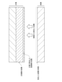
- FIG. 1 is a diagram for explaining a mechanism by which a short circuit occurs between electrodes when a secondary battery is over-discharged.
- 1 is a diagram for explaining a mechanism by which a short circuit occurs between electrodes when a secondary battery is over-discharged.
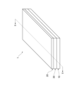
- FIG. 2 is a three-dimensional perspective view for explaining the configuration of a secondary battery.
- 1 is a diagram for explaining a configuration of a secondary battery according to a first embodiment
- FIG. 11 is a diagram for explaining the configuration of a secondary battery according to a second embodiment.
- FIG. 11 is a diagram for explaining the configuration of a secondary battery according to a second embodiment.
- FIG. 11 is a diagram for explaining the configuration of a secondary battery according to a third embodiment.
- FIG. 11 is a diagram for explaining the configuration of a secondary battery according to a third embodiment.
- 4 is a flowchart for explaining a method for manufacturing a secondary battery.
- 1 is a diagram for explaining an embodiment of a secondary battery;
- a secondary battery in one exemplary embodiment, includes a positive electrode, a first separator disposed on one side of the positive electrode, and a first negative electrode disposed in a stacking direction away from the positive electrode via the first separator, the first negative electrode including a first current collector, the first current collector including a first resin layer sandwiched between a pair of first conductive layers, and each of the pair of first conductive layers having a thickness of 0.3 ⁇ m or more and less than 1.9 ⁇ m.
- the first current collector has a first end portion extending outward from a side surface of the first current collector.
- the secondary battery further comprises a second separator disposed on the other side of the positive electrode, and a second negative electrode disposed in a stacking direction away from the positive electrode via the second separator, the second negative electrode comprising a second current collector, the second current collector comprising a second resin layer sandwiched between a pair of second conductive layers, and a second end portion extending outward from a side surface of the second current collector, and each of the pair of second conductive layers having a thickness of 0.3 ⁇ m or more and less than 1.9 ⁇ m.
- the secondary battery further includes a metal sheet arranged in parallel with the first end and the second end in the stacking direction, and the metal sheet has a first joining mark resulting from joining to either the first end or the second end.
- the secondary battery further includes a negative electrode tab electrically connected to the first negative electrode and the second negative electrode, the negative electrode tab having a first end, a second end, and a second bonding mark formed by bonding with the metal sheet, the second bonding mark being located at a different position from the first bonding mark when viewed from the stacking direction.
- the first end is recessed in a direction from the first current collector toward the metal sheet in a cross section including the first bonding mark.
- the first and second joining marks are welding marks.
- the metal sheet is constructed from a metal that includes copper.
- a laminate including a positive electrode, a separator, and a first negative electrode is enclosed inside a sealed container together with an electrolyte.
- the first negative electrode is substantially free of negative electrode active material.
- the first negative electrode further includes a negative electrode active material layer disposed on the first current collector.
- the pair of first conductive layers each have a thickness of 0.5 ⁇ m or more and less than 1.5 ⁇ m.
- each of the pair of first conductive layers is thinner than the first resin layer.
- the pair of first conductive layers is made of a metal including copper.
- secondary battery 1 includes at least some of the energy density, safety, monetary cost required for manufacturing, and manufacturing efficiency of secondary battery 1.
- secondary battery 1 is described as being a lithium ion secondary battery, but the scope of application of this disclosure is not limited to this.
- the negative electrode 20 of the secondary battery 1 in this disclosure has a negative electrode side conductive layer 222 with a thickness of 0.3 ⁇ m or more and less than 1.9 ⁇ m. Because the negative electrode side conductive layer 222 is sufficiently thin, when the secondary battery 1 is in an overdischarged state, the negative electrode side conductive layer 222 is entirely precipitated on the positive electrode 10 before a short circuit is formed (see FIG. 2). This suppresses the formation of a short circuit between the negative electrode 20 and the positive electrode 10.
- Fig. 3 is a perspective view for explaining a configuration example of the secondary battery 1.
- the secondary battery 1 includes a negative electrode 20, a separator 30, and a positive electrode 10.
- Fig. 4 is a cross-sectional view taken along line II-II of the secondary battery 1 in Fig. 3. Each component will be described in detail below with reference to Fig. 4.
- the negative electrode 20 includes a negative electrode-side current collector 22.
- the negative electrode-side current collector 22 includes a negative electrode-side resin layer 220 and a negative electrode-side conductive layer 222 disposed on both sides of the negative electrode-side resin layer 220.
- the negative electrode side resin layer 220 may be composed of a sheet-shaped (film-shaped) or fibrous resin.
- the resin may be, for example, at least one of polyolefin resins such as polyethylene terephthalate (PET), polyethylene, and polypropylene, and thermoplastic resins such as polystyrene, polyvinyl chloride, and polyamide.
- the negative electrode side resin layer 220 may be composed of at least one of the resins laminated together.
- the negative electrode side resin layer 220 is formed from a material having a melting point of 150° C. or more and 300° C. or less.
- the thickness of the negative electrode side resin layer 220 may be 3 ⁇ m or more and 10 ⁇ m or less, or 4 ⁇ m or more and 8 ⁇ m or less.
- the negative electrode side resin layer 220 can function to melt when abnormal heat is generated due to overcharging or high temperature, to damage the negative electrode 20, and to cut off the short circuit current inside the battery. This can suppress a sudden temperature rise inside the secondary battery 1 and suppress the battery from catching fire. In other words, the negative electrode side resin layer 220 can contribute to improving the safety of the secondary battery 1.
- the negative electrode side resin layer 220 may be made of an insulating material. By including the negative electrode side resin layer 220, the negative electrode side current collector 22 can be made lighter than when the negative electrode side current collector 22 is made of only a conductive layer, while ensuring the thickness (rigidity) required for the negative electrode side current collector 22.
- the negative electrode side conductive layer 222 is formed of at least one selected from the group consisting of metals that do not react with Cu, Ni, Ti, Fe, and Li, alloys thereof, and stainless steel.
- the "metal that does not react with Li” may be a metal that does not react with lithium ions or lithium metal to form an alloy in the operating state of the secondary battery 1.
- the negative electrode side conductive layer 222 is Cu.
- the negative electrode side conductive layer 222 is formed by vapor deposition, sputtering, electrolytic plating, or lamination of the above material on both surfaces of the negative electrode side resin layer 220.
- the thickness of each negative electrode side conductive layer 222 is 0.3 ⁇ m to 1.9 ⁇ m, 0.3 ⁇ m to 1.5 ⁇ m, 0.5 ⁇ m to 1.9 ⁇ m, or 0.5 ⁇ m to 1.5 ⁇ m.
- the thickness of the negative electrode side conductive layer 222 may be thinner than the thickness of the negative electrode side resin layer 220.
- the thickness of each negative electrode side conductive layer 222 may be 50% or less, 40% or less, 30% or less, 20% or less, or 10% or less of the thickness of the negative electrode side resin layer 220.
- the thickness of the negative electrode side conductive layer 222 may be thinner than the positive electrode side conductive layer 122.
- the thickness of the negative electrode side conductive layer 222 may be 50% or less, 40% or less, 30% or less, 20% or less, or 10% or less of the thickness of the positive electrode side conductive layer 122.
- the negative electrode 20 is substantially free of a negative electrode active material.
- the negative electrode 20 being "substantially free of a negative electrode active material” includes, for example, that the layer thickness of the negative electrode active material deposited on the negative electrode 20 at the end of discharge (for example, a state in which the open circuit voltage of the battery is 2.5 V or more and 3.6 V or less) is 25 ⁇ m or less.
- the layer thickness of the negative electrode active material at the end of discharge may be 20 ⁇ m or less, 15 ⁇ m or less, 10 ⁇ m or less, or 5 ⁇ m or less, or may be 0 ⁇ m.
- the secondary battery 1 may also be called an "anode-free lithium battery", a “zero anode lithium battery”, or an “anodeless lithium battery”.
- the negative electrode 20 does not have a negative electrode active material before the initial charge of the battery (the state from when the battery is assembled until the first charge). That is, the secondary battery 1 may be charged and discharged by depositing lithium metal on the negative electrode after the initial charge, and then electrolytically dissolving the deposited lithium metal. In this case, the volume and mass occupied by the negative electrode active material are suppressed, the volume and mass of the entire battery are reduced, and the energy density is, in principle, high.
- lithium metal deposits on the negative electrode does not only mean that lithium metal deposits on the surface of the negative electrode, but also includes that lithium metal deposits on the surface of a solid electrolyte interface (SEI) layer and on the surface or inside of a buffer functional layer, which will be described later.
- SEI solid electrolyte interface
- M3.0/M4.2 may be 40% or less or 35% or less. In one embodiment, the ratio M3.0/M4.2 may be 1.0% or more, 2.0% or more, 3.0% or more, or 4.0% or more.
- the thickness of the negative electrode 20 may be 1.0 ⁇ m or more and 30 ⁇ m or less. This reduces the volume occupied by the negative electrode 20 in the secondary battery 1, and improves the energy density.
- the thickness of the negative electrode 20 may be 2.0 ⁇ m or more and 20 ⁇ m or less, 2.0 ⁇ m or more and 18 ⁇ m or less, or 3.0 ⁇ m or more and 15 ⁇ m or less.
- the negative electrode 20 may be coated on at least a portion of the surface facing the positive electrode 10 with a compound (hereinafter also referred to as "negative electrode coating agent") that includes an aromatic ring to which two or more elements selected from the group consisting of N, S, and O are independently bonded.
- the negative electrode coating agent can be held on the negative electrode 20 by the above elements being coordinately bonded to the metal atoms that constitute the negative electrode 20. According to this embodiment, the non-uniform deposition reaction of lithium metal on the surface of the negative electrode 20 can be suppressed, and the lithium metal deposited on the negative electrode 20 can be suppressed from growing in a dendritic shape.
- the negative electrode coating agent is coated on at least a portion of the surface of the negative electrode 20. In one embodiment, 10% or more of the surface area may have the negative electrode coating agent, or 20% or more, 40% or more, 60% or more, or 80% or more of the surface may have the negative electrode coating agent.
- the aromatic ring contained in the anode coating agent may be an aromatic hydrocarbon, such as benzene, naphthalene, azulene, anthracene, and pyrene, and a heteroaromatic compound, such as furan, thiophene, pyrrole, imidazole, pyrazole, pyridine, pyridazine, pyrimidine, and pyrazine.
- the aromatic ring is an aromatic hydrocarbon.
- the aromatic ring is benzene or naphthalene.
- the aromatic ring is benzene.
- the negative electrode coating agent may be configured with one or more nitrogen atoms bonded to an aromatic ring.
- the negative electrode coating agent may be a compound having a structure in which a nitrogen atom is bonded to an aromatic ring and, in addition to the nitrogen atom, one or more elements selected from the group consisting of N, S, and O are each independently bonded.
- the cycle characteristics of the battery may be improved.
- the negative electrode coating agent may be, for example, at least one selected from the group consisting of benzotriazole, benzimidazole, benzimidazole thiol, benzoxazole, benzoxazole thiol, benzothiazole, and mercaptobenzothiazole, and derivatives thereof.
- the negative electrode coating agent is at least one selected from the group consisting of benzotriazole, benzimidazole, benzoxazole, and mercaptobenzothiazole, and derivatives thereof.
- the separator 30 is disposed on the negative electrode 20.
- the separator 30 is disposed on one surface of the negative electrode 20 (the surface in the negative direction of the z-axis in FIG. 4).
- the separator 30 physically and/or electrically isolates the negative electrode 20 from the positive electrode 10 and ensures ion conductivity of lithium ions.
- the separator 30 may be at least one selected from the group consisting of an insulating porous member, a polymer electrolyte, a gel electrolyte, and an inorganic solid electrolyte.
- the separator 30 may be a single member or a combination of two or more members.
- the separator 30 When the separator 30 includes an insulating porous member, the pores of the porous member are filled with a substance having ion conductivity (electrolyte, polymer electrolyte, and/or gel electrolyte, etc.). This allows the separator 30 to exhibit ion conductivity.
- a substance having ion conductivity electrolyte, polymer electrolyte, and/or gel electrolyte, etc.
- the separator 30 may exhibit ion conductivity.
- the material constituting the insulating porous member and examples of the material include insulating polymer materials, specifically, polyethylene (PE) and polypropylene (PP). That is, the separator 30 may be a porous polyethylene (PE) film, a porous polypropylene (PP) film, or a laminated structure thereof.
- the separator 30 may be coated on one or both sides with a separator coating layer. This may improve the cycle characteristics of the secondary battery 1.
- the separator coating layer may be a continuous film with a uniform thickness over 50% or more of the surface area of the separator 30.
- the separator coating layer may include a binder such as polyvinylidene fluoride (PVDF), a mixture of styrene butadiene rubber and carboxymethyl cellulose (SBR-CMC), and polyacrylic acid (PAA).
- the separator coating layer may be composed of the above binder to which inorganic particles such as silica, alumina, titania, zirconia, or magnesium hydroxide are added.
- the thickness of the separator 30 (including the coating layer if the separator 30 includes the coating layer) may be 3.0 ⁇ m or more and 40 ⁇ m or less. This can reduce the volume occupied by the separator 30 while isolating the negative electrode 20 and the positive electrode 10.
- the thickness of the separator 30 may be 5.0 ⁇ m or more, 7.0 ⁇ m or more, or 10 ⁇ m or more.
- the thickness of the separator 30 may be 30 ⁇ m or less, 20 ⁇ m or less, or 10 ⁇ m or less.
- the positive electrode 10 is disposed apart from the negative electrode 20 in the stacking direction (the direction of the z-axis in FIG. 4 ) via the separator 30.
- the positive electrode 10 includes a positive electrode-side current collector 12 and positive electrode active material layers 14 disposed on both sides of the positive electrode-side current collector 12.
- the positive electrode-side current collector 12 includes a positive electrode-side resin layer 120 and positive electrode-side conductive layers 122 disposed on both sides of the positive electrode-side resin layer 120.
- the configuration of the positive electrode-side resin layer 120 may be similar to the configuration of the negative electrode-side resin layer 220 described above, and therefore a description thereof will be omitted below.
- the positive electrode side conductive layer 122 is formed on both sides of the positive electrode side resin layer 120 so as to sandwich the positive electrode side conductive layer 120.
- the positive electrode side conductive layer 122 is in physical and/or electrical contact with the positive electrode active material layer 14 and functions to give and receive electrons to and from the positive electrode active material layer 14.
- the positive electrode side conductive layer 122 is made of a conductor that does not react with lithium ions in a battery.
- the positive electrode side conductive layer 122 is made of at least one material selected from the group consisting of aluminum, titanium, stainless steel, nickel, and alloys thereof.
- the positive electrode side conductive layer 122 is aluminum or an aluminum alloy.
- the positive electrode side conductive layer 122 is formed by vapor deposition, sputtering, electrolytic plating, or lamination of the above material on both surfaces of the positive electrode side resin layer 120.
- the thickness of each positive electrode side conductive layer 122 may be 0.5 ⁇ m or more and 5 ⁇ m or less, 0.7 ⁇ m or more and 3 ⁇ m or less, or 0.8 ⁇ m or more and 2.0 ⁇ m or less.
- the positive electrode active material layer 14 is formed on both sides of the positive electrode collector 12.
- a known material may be appropriately selected depending on the application. Thickness of the positive electrode active material layer 14 may be appropriately adjusted depending on the desired capacity and rate characteristics of the battery. In one embodiment, the thickness of each positive electrode active material layer 14 is, for example, 20 ⁇ m or more and 150 ⁇ m or less.
- the positive electrode active material layer 14 has a positive electrode active material.
- the positive electrode active material is a material for holding the carrier metal in the positive electrode active material layer 14, and can also be called a host material for the carrier metal.
- the positive electrode active material may be a material for holding lithium ions in the positive electrode active material layer 14, in which case lithium ions are loaded into and deloaded from the positive electrode active material by charging and discharging the battery. This can improve the stability and output voltage of the battery.
- the positive electrode active material is a metal oxide or a metal phosphate.
- the metal oxide may be, for example, a cobalt oxide-based compound, a manganese oxide-based compound, or a nickel oxide-based compound.
- the metal phosphate may be, for example, an iron phosphate-based compound or a cobalt phosphate-based compound.
- the positive electrode active material may be used alone or in combination of two or more.
- the content of the positive electrode active material in the positive electrode active material layer 14 may be 50% by mass or more and 100% by mass or less with respect to the entire positive electrode active material layer 14 .
- the positive electrode active material layer 14 may contain one or more components other than the positive electrode active material.
- the positive electrode active material layer 14 may include a sacrificial positive electrode material. This is a lithium-containing compound that undergoes an oxidation reaction and does not substantially undergo a reduction reaction in the charge/discharge potential range of the positive electrode active material.
- the positive electrode active material layer 14 may include a gel electrolyte.
- the gel electrolyte may improve the adhesive strength between the positive electrode active material layer 14 and the positive electrode side current collector 12.
- the gel electrolyte includes a polymer, an organic solvent, and a lithium salt.
- the polymer in the gel electrolyte may be, for example, a copolymer of polyethylene and/or polyethylene oxide, polyvinylidene fluoride, and a copolymer of polyvinylidene fluoride and hexafluoropropylene.
- the positive electrode active material layer 14 may include a conductive additive and/or a binder.
- the conductive additive is carbon black, single-walled carbon nanotubes (SWCNT), multi-walled carbon nanotubes (MWCNT), carbon nanofibers (CF), or the like.
- the binder is polyvinylidene fluoride, polytetrafluoroethylene, styrene butadiene rubber, acrylic resin, polyimide resin, or the like.
- the content of the conductive additive is 0.5% to 30% by mass or less with respect to the entire positive electrode active material layer 14. In one embodiment, the content of the binder may be 0.5% to 30% by mass or less with respect to the entire positive electrode active material layer 14.
- the positive electrode active material layer 14 may include a polymer electrolyte.
- the polymer electrolyte is a solid polymer electrolyte that mainly contains a polymer and an electrolyte, and a semi-solid polymer electrolyte that mainly contains a polymer, an electrolyte, and a plasticizer.
- the total content of the polymer electrolyte may be 0.5% by mass to 30% by mass or less with respect to the entire positive electrode active material layer 14.
- the secondary battery 1 prevents the formation of a short circuit when the secondary battery 1 is over-discharged.
- the negative electrode side conductive layer 222 dissolves entirely when the battery 1 is over-discharged. As a result, no conductive material is present on the surface of the negative electrode 20 that faces the positive electrode 10, and therefore, even if the dissolved metal precipitates on the positive electrode 10, the formation of a short circuit between the electrodes is prevented.
- the secondary battery 1 may include an electrolytic solution.
- the electrolytic solution is a liquid containing a solvent and an electrolyte, and has ion conductivity.
- the electrolytic solution may be referred to as a liquid electrolyte, and acts as a conductive path for lithium ions. Therefore, when the secondary battery 1 includes the electrolytic solution, the internal resistance is reduced, and the energy density, capacity, and cycle characteristics can be improved.
- the electrolyte may be, for example, a solution that fills the case (pouch) of the secondary battery 1. Also, for example, the electrolyte may be impregnated into the separator 30, or may be held in a polymer to form a polymer electrolyte or a gel electrolyte.
- the electrolyte contained in the electrolytic solution may be, for example, a lithium salt.
- the lithium salt may be, for example, one or a combination of two or more selected from the group consisting of LiI , LiCl, LiBr, LiF , LiBF4 , LiPF6 , LiAsF6 , LiSO3CF3 , LiN( SO2F ) 2 , LiN ( SO2CF3 ) 2 , LiN( SO2CF3CF3 ) 2 , LiB( O2C2H4 ) 2 , LiB (C2O4) 2 , LiB (O2C2H4 ) F2 , LiB( OCOCF3 ) 4 , LiNO3, and Li2SO4 .
- non-aqueous solvents containing fluorine atoms (hereinafter referred to as "fluorinated solvents”) and non-aqueous solvents not containing fluorine atoms (hereinafter referred to as “non-fluorinated solvents”) may be added as solvents contained in the electrolyte solution.
- fluorinated solvents fluorine atoms
- non-fluorinated solvents non-aqueous solvents not containing fluorine atoms
- the fluorinated solvent may be, for example, 1,1,2,2-tetrafluoroethyl-2,2,3,3-tetrafluoropropyl ether, 1,1,2,2-tetrafluoroethyl-2,2,2-trifluoroethyl ether, and 1H,1H,5H-octafluoropentyl-1,1,2,2-tetrafluoroethyl ether.
- the non-fluorinated solvent may be, for example, triethylene glycol dimethyl ether, tetraethylene glycol dimethyl ether, 1,2-dimethoxyethane, dimethoxyethane, dimethoxypropane, dimethoxybutane, diethylene glycol dimethyl ether, acetonitrile, dimethyl carbonate, diethyl carbonate, ethyl methyl carbonate, ethylene carbonate, propylene carbonate, chloroethylene carbonate, methyl acetate, ethyl acetate, propyl acetate, methyl propionate, ethyl propionate, trimethyl phosphate, triethyl phosphate, and 12-crown-4.
- the above fluorinated solvents and/or non-fluorinated solvents may be used alone or in any combination of two or more in any ratio.
- the content of the fluorinated solvent and non-fluorinated solvent is not particularly limited, and the ratio of the fluorinated solvent to the total solvent may be 0 to 100% by volume, and the ratio of the non-fluorinated solvent to the total solvent may be 0 to 100% by volume.
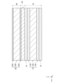
- the secondary battery 1 according to the second embodiment further includes a second negative electrode 20B and a second separator 30B, as compared with the secondary battery 1 according to the first embodiment.
- the negative electrode side current collector 22 also includes an end P extending outward from a side surface of the negative electrode side current collector 22.
- the secondary battery 1 includes a first negative electrode 20A, a first separator 30A, a positive electrode 10, a second separator 30B, and a second negative electrode 20B.
- the first negative electrode 20A includes a first current collector 22A.
- the first current collector 22A includes a first resin layer 220A and a first conductive layer 222A disposed on both sides of the first resin layer 220A.
- the first current collector 22A also includes a first end P1 extending outward from the side surface of the first current collector 22A (the positive direction of the x-axis in FIG. 5). In one embodiment, the first end P1 may be a part of the first current collector 22A as shown in FIG. 5.
- the second negative electrode 20B includes a second current collector 22B.
- the second current collector 22B includes a second resin layer 220B and a second conductive layer 222B disposed on both sides of the second resin layer 220B.
- the second current collector 22B also includes a second end P2 extending outward from the side surface of the second current collector 22B (the positive direction of the x-axis in FIG. 5). In one embodiment, the second end P2 may be a part of the second current collector 22B as shown in FIG. 5.
- the configuration of the first resin layer 220A and the second resin layer 220B may be the same as that of the negative electrode side resin layer 220 according to the first embodiment. Furthermore, the configuration of the first conductive layer 222A and the second conductive layer 222B may be the same as that of the negative electrode side resin layer 220 according to the first embodiment. Therefore, in the following, the description of the first resin layer 220A, the second resin layer 220B, the first conductive layer 222A, and the second conductive layer 222B will be omitted.
- the configuration of the first separator 30A and the second separator 30B may be the same as that of the separator 30 according to the first embodiment. Therefore, the following description of the first separator 30A and the second separator 30B will be omitted.
- the first negative electrode 20A and the second negative electrode 20B are referred to as the "negative electrode 20"
- the first current collector 22A and the second current collector 22B are referred to as the "negative electrode side current collector 22”
- the first resin layer 220A and the second resin layer 220B are referred to as the "negative electrode side resin layer 220”
- the first conductive layer 222A and the second conductive layer 222B are referred to as the “negative electrode side conductive layer 222”
- the first end P1 and the second end P2 are referred to as the "end P".
- the positive electrode side current collector 12 of the positive electrode 10 of the first embodiment further includes an end Q exposed from the positive electrode active material layer 14.
- the secondary battery 1 may be constructed by stacking multiple negative electrodes 20, separators 30, and positive electrodes 10.
- Each end P may extend in the positive direction of the y-axis as viewed from the secondary battery 1, and may be aligned in a row with each other in the stacking direction.
- Each end P is electrically joined to the negative electrode tab 42.
- an end Q of each positive electrode 10 may extend in the negative direction of the y-axis as viewed from the secondary battery 1, and may be aligned in a row with each other in the stacking direction.
- Each end Q is electrically joined to the positive electrode tab 40.
- the configuration of the secondary battery 1 according to the second embodiment can improve the energy density of the secondary battery 1. For example, this is because lithium ions can be stored between the positive electrode 10 and the first negative electrode 20A, and between the positive electrode 10 and the second negative electrode 20B.
- this configuration can further improve the usefulness of the secondary battery 1. This is because, by electrically connecting the negative electrode tab 42 to each end P, electricity can be passed from the negative electrode tab 42 to multiple negative electrodes 20. Furthermore, by electrically connecting the positive electrode tab 40 to each end Q, electricity can be passed from the positive electrode tab 40 to multiple positive electrodes 10.
- the secondary battery 1 according to the third embodiment further includes a metal sheet MS and a negative electrode tab 42.
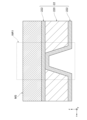
- the configuration of the secondary battery 1 according to the third embodiment will be described with reference to Figs. 7 to 8.
- Figure 7 shows the end P, metal sheet MS, and negative electrode tab 42 joined together.
- the metal sheet MS is arranged next to the end P in the stacking direction.
- the metal sheet MS has a first bonding mark WR1 due to bonding with the end P.
- the metal sheet MS is made of at least one material selected from the group consisting of copper, titanium, stainless steel, nickel, and alloys thereof.
- the metal sheet MS is a hard copper foil.
- the metal sheet MS is a soft copper foil.
- the metal sheet MS may be made of the same material as the negative electrode side conductive layer 222.
- the negative electrode tab 42 has a second bonding mark WR2 due to bonding with the end P. The second bonding mark WR2 is located at a different position from the first bonding mark WR1 when viewed from the stacking direction.
- the first joining mark WR1 has an area where the metal sheet MS and the end P are integrated.
- the second joining mark WR2 has an area where the negative electrode tab 42, the metal sheet MS, and the end P are integrated. That is, the end P is directly electrically connected to the negative electrode tab 42 at the second joining mark WR2, and is indirectly electrically connected to the negative electrode tab 42 via the metal sheet MS, which is electrically connected at the first joining mark WR1.
- the metal sheet MS and the negative electrode tab 42 are collectively referred to as the "joining objects.”
- the joining object is joined to the end P by a method that does not inhibit the flow of electricity between the end P and the joining object.
- the joining object may be joined by a method that creates an atomic level bond (e.g., a metallic bond) between the end P and the joining object. Such a bond increases the thermal conductivity between the metal sheet MS and the end P.
- the object to be joined may be joined to the end P by any of metallurgical joining, mechanical joining, and chemical joining.
- Metallurgical joining includes welding, pressure welding, and brazing.
- Welding includes, for example, arc welding, electron beam welding, gas welding, and laser welding.
- Pressure welding includes, for example, ultrasonic welding, friction welding, and diffusion welding.
- Brazing includes, for example, soldering.
- Mechanical joining includes, for example, riveting, crimping, bolt joining, shrink fitting, and folding.
- Chemical joining includes, for example, gluing with an adhesive.
- the objects to be joined are joined to the end P by ultrasonic joining.
- Ultrasonic joining is a joining method that creates an atomic-level bond between two metals by applying pressure and vibration between the two metals.
- the joining marks formed by ultrasonic joining can also be called welding marks, since the metals may melt.
- Ultrasonic bonding makes it possible to bond the objects to be bonded to the end P in a short time. Furthermore, ultrasonic bonding makes it possible to bond the objects to be bonded to the end P without applying heat. Furthermore, ultrasonic bonding does not consume other materials for bonding. As described above, ultrasonic bonding can improve the manufacturing efficiency of the secondary battery 1.
- the ultrasonic bonding may be rotary ultrasonic bonding, which allows for continuous processing.
- the cross section including the first bonding mark WR1 has a concave shape in the direction from the negative electrode side collector 22 toward the metal sheet MS.
- the first bonding mark WR1 is formed by applying pressure from the surface of the negative electrode side collector 22 on which the metal sheet MS is not provided toward the surface of the negative electrode side collector 22 on which the metal sheet MS is provided.
- the first bonding mark WR1 is formed by pressing an ultrasonic bonding horn against the negative electrode side collector 22. At this time, the opposite surface may be deformed for manufacturing reasons (e.g., pressure applied by an anvil corresponding to the horn, etc.).
- the negative electrode tabs 42 are arranged to be aligned in the stacking direction (the direction of the z-axis) with respect to each end P of the negative electrode collector 22 and each metal sheet MS. In one embodiment, the negative electrode tabs 42 may be arranged above or below the end P of each negative electrode collector 22 and each metal sheet MS. In one embodiment, the negative electrode tabs 42 may be arranged between an end P and an adjacent end P.
- the negative electrode tab 42 is made of a conductive material.
- the negative electrode tab 42 may be made of, for example, copper or an alloy containing copper.
- the negative electrode tab 42 is joined to each end P of each negative electrode collector 22 and each metal sheet MS. As a result, the negative electrode tab 42 is electrically connected to each negative electrode 20 via each end P.
- a second joint mark WR2 is formed on the negative electrode tab 42 by joining with each end P.
- the second joint mark WR2 may be one or more points (spots) in a plan view, or may be a continuous line or surface.
- the first joint mark WR1 is formed for each end P. In other words, one first joint mark WR1 is not formed across multiple end P.
- the second joint mark WR2 is formed over the entire negative electrode tab 42, each end P, and each metal sheet MS. In other words, the second joint mark WR2 is formed continuously in the stacking direction from the negative electrode tab 42 to the end P of the lowest layer.
- the negative electrode resin layer 220 can suppress a sudden temperature rise inside the secondary battery 1 in the event of abnormal heat generation due to overcharging or high temperature conditions, and can suppress battery ignition.
- a collector having a resin layer sandwiched between conductive layers As the number of collectors increases or the thickness of the resin layers increases, it becomes more difficult to bond the end of the collector to the electrode tab and ensure stable bonding quality (variation control) in each layer. For example, if a strong force is applied in an attempt to weld the electrode tab to all the ends, the conductive layer at the end may be damaged or broken if the conductive layer is thin. On the other hand, if the electrode tab is welded with a force that does not damage the conductive layer, the bond may be insufficient and the resistance between the end of the collector and the electrode tab may increase.
- a metal sheet MS is disposed between at least one end P.
- the metal sheet MS functions as an additional conductive layer of the negative electrode side conductive layer 222 at the second joint mark WR2, and increases the ratio of the conductive layer to the negative electrode side resin layer 220. Therefore, an increase in resistance at the second joint mark WR2 can be suppressed. This can improve the output characteristics of the secondary battery 1.
- the metal sheet MS can also function as a protective layer for the negative electrode side conductive layer 222 at the end P when the negative electrode tab 42 and the end P are joined.
- the resistance of the second bond mark WR2 may be 5.0 m ⁇ or less, 3.0 m ⁇ or less, 1.0 m ⁇ or less, or 0.5 m ⁇ or less.
- a metal sheet MS is joined to the first end P1 of the first negative electrode 20A (S10). This forms a first joining mark WR1 between the first negative electrode 20A and the metal sheet MS (see FIG. 7).
- the metal sheet MS is joined to the second end P2 of the second negative electrode 20B (S12).
- a first joining mark WR1 is formed between the second negative electrode 20B and the metal sheet MS (see FIG. 7).
- the joining of the metal sheet MS in steps S10 and S12 is hereinafter also referred to as "preliminary joining". The preliminary joining is performed prior to joining of the first negative electrode 20A and/or the second negative electrode 20B to the negative electrode tab 42.
- the first negative electrode 20A with the metal sheet MS bonded thereto, the first separator 30A, the positive electrode 10, the second separator 30B, and the second negative electrode 20B with the metal sheet MS bonded thereto are stacked in this order (S14, see Figure 5).
- first end P1, the second end P2, and the metal sheets MS joined to each of them are joined to the negative electrode tab 42 (S16).
- the positive electrode 10 is electrically connected to the positive electrode tab 40 (S18).
- the laminate obtained up to S18 is sealed in a sealed container (including a housing or pouch) together with the electrolyte (S20). If preliminary joining (S10 and S12) is not performed, the metal sheet MS may be stacked on the first negative electrode 20A and the second negative electrode 20B in step ST14, and the first end P1, the second end P2, and the metal sheet MS stacked on each of them may be joined together to the negative electrode tab 42 in step ST16.
- the secondary battery 1 is charged and discharged by connecting the positive electrode tab 40 to one end of an external circuit and the negative electrode tab 42 to the other end of the external circuit.
- the external circuit may be, for example, a resistor, a power source, an apparatus, a device, another battery, or a potentiostat.
- the ends P of the multiple negative electrodes 20 may be connected to the external circuit at the same potential.
- the negative electrode ends Q of the multiple positive electrodes 10 may be connected to the external circuit at the same potential.
- the secondary battery 1 When a voltage is applied between the positive electrode tab 40 and the negative electrode tab 42 such that a current flows from the negative electrode tab 42 through an external circuit to the positive electrode tab 40, the secondary battery 1 is charged and lithium metal is precipitated on the negative electrode 20.
- the positive electrode tab 40 and the negative electrode tab 42 of the charged secondary battery 1 are connected via a desired external circuit, the secondary battery 1 is discharged and the lithium metal in the negative electrode 20 is electrolytically dissolved.
- the secondary battery 1 may have a solid electrolyte interface layer (SEI layer) formed on the surface of the negative electrode 20 or the surface of the separator 30 (i.e., the interface between the negative electrode 20 and the separator 30) by the first charge (initial charge) after the battery is assembled.
- SEI layer may contain, for example, an inorganic compound containing lithium, or an organic compound containing lithium.
- the thickness of the SEI layer is 1.0 nm or more and 10 ⁇ m or less.
- the secondary battery 1 described above can improve the usefulness of the battery.
- the negative electrode 20 is described as having substantially no negative electrode active material, but this is not limited thereto.
- the negative electrode 20 may further include a negative electrode active material layer provided on the negative electrode side current collector 22. That is, the negative electrode active material layer may be present between the separator 30 and the negative electrode side current collector 22.
- the negative electrode active material layer faces the positive electrode active material layer 14 with the separator 30 sandwiched therebetween.
- the negative electrode active material layer is disposed on both sides of the negative electrode collector 22. In one embodiment, the negative electrode active material layer may be disposed on only one side of the negative electrode collector 22.
- the negative electrode active material layer is a material that causes an electrode reaction, i.e., an oxidation reaction and a reduction reaction, at the negative electrode.
- the negative electrode active material layer may be, for example, lithium metal and an alloy containing lithium metal, a carbon-based material, a metal oxide, a metal that alloys with lithium and an alloy containing the metal, etc.
- the carbon-based material may be, for example, graphene, graphite, hard carbon, carbon nanotubes, etc.
- the metal oxide may be, for example, a titanium oxide-based compound, a cobalt oxide-based compound, etc.
- the metal that alloys with lithium may be, for example, silicon, silicon oxide, germanium, tin, lead, aluminum, and gallium, and these may be pre-doped with lithium.
- the usefulness of the secondary battery 1 was confirmed by an experiment based on the forced discharge test stipulated in T8 of Section 38.3.4.8 of "UN 38.3 United Nations Recommended Transport Tests for Testing the Safety of Lithium-Ion Batteries During Transport". Specifically, a 12V DC power source was connected in series to the secondary battery 1 having the same configuration as the third embodiment, and the secondary battery 1 was forcibly discharged at an initial current (e.g., 2C) for 30 minutes at room temperature. After the forced discharge, the secondary battery 1 was observed for 7 days.
- an initial current e.g., 2C
- the welded portion of the secondary battery 1 i.e., the joint between the negative electrode tab 42 and the end P
- the current was calculated from the voltage drop in a resistor connected in series to the secondary battery 1.
- a negative electrode 20 was used that had a negative electrode side conductive layer 222 made of copper and a negative electrode side resin layer 220 made of PET with a thickness of 4.5 ⁇ m.
- a CCS ceramic coated separator
- a 4M dimethoxyethane solution of LiFSI lithium bis(fluorosulfonyl)imide was used as the electrolyte.
- Example N2 when the thickness of the negative electrode side conductive layer 222 was 2.0 ⁇ m, the sealed container cracked (whether or not the sealed container cracked: yes). On the other hand, according to Example L4, when the thickness of the negative electrode side conductive layer 222 was 1.5 ⁇ m, the sealed container did not crack (whether or not the sealed container cracked: no).
- the thickness of the negative electrode side conductive layer 222 is 0.3 ⁇ m or more and less than 1.9 ⁇ m, the probability of the sealed container cracking can be reduced regardless of whether the metal sheet MS is joined or not.
- the thickness of the negative electrode side conductive layer 222 is 0.5 ⁇ m or more and 1.5 ⁇ m or less, the sealed container does not crack.
- the thickness of the negative electrode side conductive layer 222 is large (e.g., 2.0 ⁇ m or more), as described above, a short circuit occurs between the electrodes due to the elution of metal in an overdischarge state, and the sealed container cracks due to the heat generated by the short circuit.
- the thickness of the negative electrode side conductive layer 222 is small (e.g., 0.2 ⁇ m or less), the resistance of the negative electrode side current collector 22 increases, and the load characteristics of the secondary battery 1 as a whole deteriorate.
- Example L2 Effect of pre-joining of metal sheet MS on weld fracture
- Example L3 when the metal sheets MS were not pre-joined, the weld fractured did not occur (whether or not the weld fractured: no).
- Embodiments of the present disclosure further include the following aspects.
- the secondary battery 1 comprises:
- Appendix 2 The secondary battery 1 described in Appendix 1, wherein the first current collector 22A has a first end P1 extending outward from a side surface of the first current collector 22A.
- the secondary battery 1 (Appendix 3) a second separator 30B disposed on the other side of the positive electrode 10; a second negative electrode (20B) disposed apart from the positive electrode (10) in the stacking direction via a second separator (30B), the second negative electrode (20B) comprising a second current collector (22B), the second current collector (22B) comprising a second resin layer (220B) sandwiched between a pair of second conductive layers (222B), and comprising a second end portion (P2) extending outward from a side surface of the second current collector (22B), each of the pair of second conductive layers (222B) having a thickness of 0.3 ⁇ m or more and less than 1.9 ⁇ m;
- the secondary battery 1 according to claim 2, further comprising:
- the secondary battery 1 described in Appendix 3 further comprises a metal sheet MS arranged in parallel with the first end P1 and the second end P2 in the stacking direction, and the metal sheet MS has a first joining mark WR1 due to joining with either the first end P1 or the second end P2.
- the secondary battery 1 described in Appendix 4 further comprising a negative electrode tab 42 electrically connected to the first negative electrode 20A and the second negative electrode 20B, the negative electrode tab 42 having a first end P1, a second end P2, and a second joint mark WR2 formed by joining with the metal sheet MS, the second joint mark WR2 being in a position different from the first joint mark WR1 when viewed from the stacking direction.
- 1 secondary battery
- 10 positive electrode
- 20A first negative electrode
- 20B second negative electrode
- 22A first current collector
- 22B second current collector
- 24 negative electrode active material layer
- 220A first resin layer
- 220B second resin layer
- 30A first separator
- 30B second separator
- 222A first conductive layer
- 222B second conductive layer
- 40 positive electrode tab
- 42 negative electrode tab
- P1 first end
- P2 second end
- MS metal sheet
- LM intermediate laminate
- WR1 first bonding mark
- WR2 second bonding mark
Landscapes
- Chemical & Material Sciences (AREA)
- Chemical Kinetics & Catalysis (AREA)
- Electrochemistry (AREA)
- General Chemical & Material Sciences (AREA)
- Engineering & Computer Science (AREA)
- Materials Engineering (AREA)
- Composite Materials (AREA)
- Manufacturing & Machinery (AREA)
- Secondary Cells (AREA)
Priority Applications (6)
| Application Number | Priority Date | Filing Date | Title |
|---|---|---|---|
| JP2025525450A JPWO2024252474A1 (enExample) | 2023-06-05 | 2023-06-05 | |
| CN202380098098.6A CN121079797A (zh) | 2023-06-05 | 2023-06-05 | 二次电池 |
| KR1020257040150A KR20260005976A (ko) | 2023-06-05 | 2023-06-05 | 이차 전지 |
| EP23940581.4A EP4723248A1 (en) | 2023-06-05 | 2023-06-05 | Secondary battery |
| PCT/JP2023/020824 WO2024252474A1 (ja) | 2023-06-05 | 2023-06-05 | 2次電池 |
| US19/408,712 US20260088307A1 (en) | 2023-06-05 | 2025-12-04 | Secondary battery |
Applications Claiming Priority (1)
| Application Number | Priority Date | Filing Date | Title |
|---|---|---|---|
| PCT/JP2023/020824 WO2024252474A1 (ja) | 2023-06-05 | 2023-06-05 | 2次電池 |
Related Child Applications (1)
| Application Number | Title | Priority Date | Filing Date |
|---|---|---|---|
| US19/408,712 Continuation US20260088307A1 (en) | 2023-06-05 | 2025-12-04 | Secondary battery |
Publications (1)
| Publication Number | Publication Date |
|---|---|
| WO2024252474A1 true WO2024252474A1 (ja) | 2024-12-12 |
Family
ID=93795131
Family Applications (1)
| Application Number | Title | Priority Date | Filing Date |
|---|---|---|---|
| PCT/JP2023/020824 Ceased WO2024252474A1 (ja) | 2023-06-05 | 2023-06-05 | 2次電池 |
Country Status (6)
| Country | Link |
|---|---|
| US (1) | US20260088307A1 (enExample) |
| EP (1) | EP4723248A1 (enExample) |
| JP (1) | JPWO2024252474A1 (enExample) |
| KR (1) | KR20260005976A (enExample) |
| CN (1) | CN121079797A (enExample) |
| WO (1) | WO2024252474A1 (enExample) |
Citations (11)
| Publication number | Priority date | Publication date | Assignee | Title |
|---|---|---|---|---|
| JPH11238515A (ja) * | 1998-02-20 | 1999-08-31 | Kao Corp | 非水系二次電池用負極 |
| JPH11238514A (ja) * | 1998-02-20 | 1999-08-31 | Kao Corp | 非水系二次電池用正極 |
| JP2001052681A (ja) * | 1999-08-05 | 2001-02-23 | Hitachi Maxell Ltd | ポリマー電解質電池 |
| WO2012118127A1 (ja) * | 2011-03-03 | 2012-09-07 | シャープ株式会社 | 非水系二次電池 |
| JP2019140054A (ja) * | 2018-02-15 | 2019-08-22 | Tdk株式会社 | 正極及び非水電解液二次電池 |
| JP2019186202A (ja) * | 2018-03-30 | 2019-10-24 | 寧徳時代新能源科技股▲分▼有限公司Contemporary Amperex Technology Co., Limited | 集電体、それを有する電極シート及び電気化学デバイス |
| CN113196532A (zh) * | 2019-11-27 | 2021-07-30 | 索特利亚电池创新集团公司 | 具有内部熔断器的储能装置中的电池连接器和金属化膜组件 |
| WO2021261029A1 (ja) * | 2020-06-25 | 2021-12-30 | 株式会社村田製作所 | 二次電池 |
| WO2022208770A1 (ja) * | 2021-03-31 | 2022-10-06 | Tdk株式会社 | 蓄電デバイス用電極、蓄電デバイスおよび二次電池 |
| US11482711B2 (en) | 2017-09-09 | 2022-10-25 | Soteria Battery Innovation Group, Inc. | Tabless cell utilizing metallized film current collectors |
| JP2022175835A (ja) * | 2021-05-14 | 2022-11-25 | プライムプラネットエナジー&ソリューションズ株式会社 | 二次電池の集電体および二次電池 |
-
2023
- 2023-06-05 JP JP2025525450A patent/JPWO2024252474A1/ja active Pending
- 2023-06-05 WO PCT/JP2023/020824 patent/WO2024252474A1/ja not_active Ceased
- 2023-06-05 EP EP23940581.4A patent/EP4723248A1/en active Pending
- 2023-06-05 KR KR1020257040150A patent/KR20260005976A/ko active Pending
- 2023-06-05 CN CN202380098098.6A patent/CN121079797A/zh active Pending
-
2025
- 2025-12-04 US US19/408,712 patent/US20260088307A1/en active Pending
Patent Citations (11)
| Publication number | Priority date | Publication date | Assignee | Title |
|---|---|---|---|---|
| JPH11238515A (ja) * | 1998-02-20 | 1999-08-31 | Kao Corp | 非水系二次電池用負極 |
| JPH11238514A (ja) * | 1998-02-20 | 1999-08-31 | Kao Corp | 非水系二次電池用正極 |
| JP2001052681A (ja) * | 1999-08-05 | 2001-02-23 | Hitachi Maxell Ltd | ポリマー電解質電池 |
| WO2012118127A1 (ja) * | 2011-03-03 | 2012-09-07 | シャープ株式会社 | 非水系二次電池 |
| US11482711B2 (en) | 2017-09-09 | 2022-10-25 | Soteria Battery Innovation Group, Inc. | Tabless cell utilizing metallized film current collectors |
| JP2019140054A (ja) * | 2018-02-15 | 2019-08-22 | Tdk株式会社 | 正極及び非水電解液二次電池 |
| JP2019186202A (ja) * | 2018-03-30 | 2019-10-24 | 寧徳時代新能源科技股▲分▼有限公司Contemporary Amperex Technology Co., Limited | 集電体、それを有する電極シート及び電気化学デバイス |
| CN113196532A (zh) * | 2019-11-27 | 2021-07-30 | 索特利亚电池创新集团公司 | 具有内部熔断器的储能装置中的电池连接器和金属化膜组件 |
| WO2021261029A1 (ja) * | 2020-06-25 | 2021-12-30 | 株式会社村田製作所 | 二次電池 |
| WO2022208770A1 (ja) * | 2021-03-31 | 2022-10-06 | Tdk株式会社 | 蓄電デバイス用電極、蓄電デバイスおよび二次電池 |
| JP2022175835A (ja) * | 2021-05-14 | 2022-11-25 | プライムプラネットエナジー&ソリューションズ株式会社 | 二次電池の集電体および二次電池 |
Also Published As
| Publication number | Publication date |
|---|---|
| JPWO2024252474A1 (enExample) | 2024-12-12 |
| EP4723248A1 (en) | 2026-04-08 |
| KR20260005976A (ko) | 2026-01-12 |
| US20260088307A1 (en) | 2026-03-26 |
| CN121079797A (zh) | 2025-12-05 |
Similar Documents
| Publication | Publication Date | Title |
|---|---|---|
| US20250239622A1 (en) | Lithium secondary battery and method for manufacturing same | |
| US20260074384A1 (en) | Electrode sheet and secondary battery | |
| JP7519121B2 (ja) | 電池及びその製造方法 | |
| JPH10112323A (ja) | 電 池 | |
| WO2025126407A1 (ja) | リチウム2次電池及びリチウム2次電池の製造方法 | |
| US20260088307A1 (en) | Secondary battery | |
| JP7492797B1 (ja) | リチウム2次電池 | |
| JP7752450B2 (ja) | リチウム2次電池 | |
| JP7784180B2 (ja) | リチウム2次電池 | |
| JP7551200B1 (ja) | 2次電池 | |
| JP7498994B1 (ja) | リチウム2次電池 | |
| WO2025220215A1 (ja) | 2次電池 | |
| WO2025220213A1 (ja) | 2次電池 |
Legal Events
| Date | Code | Title | Description |
|---|---|---|---|
| 121 | Ep: the epo has been informed by wipo that ep was designated in this application |
Ref document number: 23940581 Country of ref document: EP Kind code of ref document: A1 |
|
| ENP | Entry into the national phase |
Ref document number: 2025525450 Country of ref document: JP Kind code of ref document: A |
|
| ENP | Entry into the national phase |
Ref document number: 1020257040150 Country of ref document: KR Free format text: ST27 STATUS EVENT CODE: A-0-1-A10-A15-NAP-PA0105 (AS PROVIDED BY THE NATIONAL OFFICE) |
|
| WWE | Wipo information: entry into national phase |
Ref document number: 202517121880 Country of ref document: IN |
|
| WWP | Wipo information: published in national office |
Ref document number: 202517121880 Country of ref document: IN |
|
| ENP | Entry into the national phase |
Ref document number: 2023940581 Country of ref document: EP Effective date: 20260105 |
|
| WWE | Wipo information: entry into national phase |
Ref document number: 2023940581 Country of ref document: EP |
|
| NENP | Non-entry into the national phase |
Ref country code: DE |
|
| ENP | Entry into the national phase |
Ref document number: 2023940581 Country of ref document: EP Effective date: 20260105 |
|
| ENP | Entry into the national phase |
Ref document number: 2023940581 Country of ref document: EP Effective date: 20260105 |
|
| ENP | Entry into the national phase |
Ref document number: 2023940581 Country of ref document: EP Effective date: 20260105 |
|
| ENP | Entry into the national phase |
Ref document number: 2023940581 Country of ref document: EP Effective date: 20260105 |
|
| ENP | Entry into the national phase |
Ref document number: 2023940581 Country of ref document: EP Effective date: 20260105 |
|
| WWP | Wipo information: published in national office |
Ref document number: 2023940581 Country of ref document: EP |