WO2024252453A1 - サンプル溶液分離デバイス、サンプル溶液分離システム、及びサンプル溶液分離方法 - Google Patents
サンプル溶液分離デバイス、サンプル溶液分離システム、及びサンプル溶液分離方法 Download PDFInfo
- Publication number
- WO2024252453A1 WO2024252453A1 PCT/JP2023/020780 JP2023020780W WO2024252453A1 WO 2024252453 A1 WO2024252453 A1 WO 2024252453A1 JP 2023020780 W JP2023020780 W JP 2023020780W WO 2024252453 A1 WO2024252453 A1 WO 2024252453A1
- Authority
- WO
- WIPO (PCT)
- Prior art keywords
- sample solution
- opening
- microchambers
- flow path
- solid phase
- Prior art date
- Legal status (The legal status is an assumption and is not a legal conclusion. Google has not performed a legal analysis and makes no representation as to the accuracy of the status listed.)
- Ceased
Links
Images




Classifications
-
- G—PHYSICS
- G01—MEASURING; TESTING
- G01N—INVESTIGATING OR ANALYSING MATERIALS BY DETERMINING THEIR CHEMICAL OR PHYSICAL PROPERTIES
- G01N33/00—Investigating or analysing materials by specific methods not covered by groups G01N1/00 - G01N31/00
- G01N33/48—Biological material, e.g. blood, urine; Haemocytometers
- G01N33/483—Physical analysis of biological material
-
- B—PERFORMING OPERATIONS; TRANSPORTING
- B01—PHYSICAL OR CHEMICAL PROCESSES OR APPARATUS IN GENERAL
- B01L—CHEMICAL OR PHYSICAL LABORATORY APPARATUS FOR GENERAL USE
- B01L3/00—Containers or dishes for laboratory use, e.g. laboratory glassware; Droppers
- B01L3/50—Containers for the purpose of retaining a material to be analysed, e.g. test tubes
- B01L3/502—Containers for the purpose of retaining a material to be analysed, e.g. test tubes with fluid transport, e.g. in multi-compartment structures
- B01L3/5027—Containers for the purpose of retaining a material to be analysed, e.g. test tubes with fluid transport, e.g. in multi-compartment structures by integrated microfluidic structures, i.e. dimensions of channels and chambers are such that surface tension forces are important, e.g. lab-on-a-chip
- B01L3/502753—Containers for the purpose of retaining a material to be analysed, e.g. test tubes with fluid transport, e.g. in multi-compartment structures by integrated microfluidic structures, i.e. dimensions of channels and chambers are such that surface tension forces are important, e.g. lab-on-a-chip characterised by bulk separation arrangements on lab-on-a-chip devices, e.g. for filtration or centrifugation
-
- B—PERFORMING OPERATIONS; TRANSPORTING
- B01—PHYSICAL OR CHEMICAL PROCESSES OR APPARATUS IN GENERAL
- B01L—CHEMICAL OR PHYSICAL LABORATORY APPARATUS FOR GENERAL USE
- B01L2300/00—Additional constructional details
- B01L2300/06—Auxiliary integrated devices, integrated components
- B01L2300/0681—Filter
-
- B—PERFORMING OPERATIONS; TRANSPORTING
- B01—PHYSICAL OR CHEMICAL PROCESSES OR APPARATUS IN GENERAL
- B01L—CHEMICAL OR PHYSICAL LABORATORY APPARATUS FOR GENERAL USE
- B01L2300/00—Additional constructional details
- B01L2300/08—Geometry, shape and general structure
- B01L2300/0809—Geometry, shape and general structure rectangular shaped
- B01L2300/0816—Cards, e.g. flat sample carriers usually with flow in two horizontal directions
-
- B—PERFORMING OPERATIONS; TRANSPORTING
- B01—PHYSICAL OR CHEMICAL PROCESSES OR APPARATUS IN GENERAL
- B01L—CHEMICAL OR PHYSICAL LABORATORY APPARATUS FOR GENERAL USE
- B01L2300/00—Additional constructional details
- B01L2300/08—Geometry, shape and general structure
- B01L2300/0861—Configuration of multiple channels and/or chambers in a single devices
- B01L2300/0864—Configuration of multiple channels and/or chambers in a single devices comprising only one inlet and multiple receiving wells, e.g. for separation, splitting
-
- B—PERFORMING OPERATIONS; TRANSPORTING
- B01—PHYSICAL OR CHEMICAL PROCESSES OR APPARATUS IN GENERAL
- B01L—CHEMICAL OR PHYSICAL LABORATORY APPARATUS FOR GENERAL USE
- B01L2400/00—Moving or stopping fluids
- B01L2400/04—Moving fluids with specific forces or mechanical means
- B01L2400/0475—Moving fluids with specific forces or mechanical means specific mechanical means and fluid pressure
- B01L2400/0487—Moving fluids with specific forces or mechanical means specific mechanical means and fluid pressure fluid pressure, pneumatics
-
- B—PERFORMING OPERATIONS; TRANSPORTING
- B01—PHYSICAL OR CHEMICAL PROCESSES OR APPARATUS IN GENERAL
- B01L—CHEMICAL OR PHYSICAL LABORATORY APPARATUS FOR GENERAL USE
- B01L2400/00—Moving or stopping fluids
- B01L2400/04—Moving fluids with specific forces or mechanical means
- B01L2400/0475—Moving fluids with specific forces or mechanical means specific mechanical means and fluid pressure
- B01L2400/0487—Moving fluids with specific forces or mechanical means specific mechanical means and fluid pressure fluid pressure, pneumatics
- B01L2400/049—Moving fluids with specific forces or mechanical means specific mechanical means and fluid pressure fluid pressure, pneumatics vacuum
Definitions
- the present invention relates to a sample solution separation device, a sample solution separation system, and a sample solution separation method for separating a sample solution.
- Digital PCR (Polymerase Chain Reaction) is a technology that detects nucleic acids with high sensitivity, and compared to conventional real-time quantitative PCR, it can detect low-frequency gene mutations.
- Patent Document 1 discloses a method in which a port is sealed to create a vacuum inside the container and the sample solution is drawn into the container.
- Non-Patent Document 1 discloses a method in which the container is degassed, the outlet valve is closed, and the inlet valve is opened to put in the solution.
- Patent Document 2 discloses a configuration in which a gas-liquid separation filter is used to eject the solution without wasting it.
- a sample solution containing the target DNA is separated into multiple compartments, and PCR is performed on each compartment to determine the type of DNA present in each compartment.
- the target DNA can be measured with high sensitivity.
- one suitable application is liquid biopsy to detect cell-free DNA (cfDNA), which exists in trace amounts in blood.
- Cell-free DNA may contain ctDNA (circulating tumor DNA), which is DNA derived from tumors, and by measuring the type and proportion of mutations in ctDNA, it is expected to be used in cancer diagnosis, treatment selection, and monitoring of treatment effectiveness.
- cfDNA and ctDNA are present in blood in minute quantities, they need to be measured with high sensitivity.
- digital PCR the sample solution is separated into multiple micro-volume chambers for measurement. In this process, not all of the sample solution can be used, and some solution cannot be separated into micro-volume chambers and cannot be measured; this results in dead volume.
- To measure with high sensitivity it is necessary to measure as much of the collected sample solution as possible. In other words, it is necessary to reduce the dead volume of the sample solution.
- the present invention has been made in consideration of the above, and one of its objectives is to provide a sample solution separation device, a sample solution separation system, and a sample solution separation method that can reduce the dead volume of the sample solution.
- the sample solution separation device of the present invention is a sample solution separation device that separates a sample solution, and includes a plurality of microchambers, a flow path connecting the plurality of microchambers, a first opening that is an inlet for the sample solution to the flow path, a valve provided between the first opening and the plurality of microchambers, a second opening that is an inlet for a separation liquid to the flow path separating the plurality of microchambers in which the sample solution is contained and is provided on the opposite side of the first opening across the plurality of microchambers, and a solid phase provided between the second opening and the plurality of microchambers, the solid phase being breathable, water repellent to the sample solution, and permeable to the separation liquid.
- the sample solution separation system of the present invention is a sample solution separation device that separates a sample solution, and includes a plurality of microchambers, a flow path connecting the plurality of microchambers, a first opening that is an inlet for the sample solution to the flow path, a valve provided between the first opening and the plurality of microchambers, a second opening that is an inlet for a separation liquid to the flow path separating the plurality of microchambers in which the sample solution is contained and is provided on the opposite side of the first opening across the plurality of microchambers, and a solid phase provided between the second opening and the plurality of microchambers, the solid phase being breathable, water repellent to the sample solution, and permeable to the separation liquid, a pump that degasses the air in the plurality of microchambers and the flow path through the solid phase from the second opening, valve control means that opens the valve, and separation liquid introduction means that introduces the separation liquid from the second opening.
- the sample solution separation method of the present invention includes preparing a sample solution separation device that separates a sample solution, the sample solution separation device including a plurality of microchambers, a flow path connecting the plurality of microchambers, a first opening that is an inlet for the sample solution to the flow path, a valve provided between the first opening and the plurality of microchambers, a second opening that is an inlet for a separation liquid to the flow path separating the plurality of microchambers in which the sample solution is contained and is provided on the opposite side of the first opening across the plurality of microchambers, and a solid phase provided between the second opening and the plurality of microchambers, the solid phase being breathable, water repellent to the sample solution, and permeable to the separation liquid; degassing the plurality of microchambers and the flow path through the solid phase; opening the valve to introduce the sample solution into the plurality of microchambers and the flow path from the first opening; and introducing the separation liquid into the flow path from the second opening through
- sample solution separation device sample solution separation system, and sample solution separation method of the present invention, it is possible to reduce the dead volume of the sample solution when separating the sample solution into a plurality of microchambers.
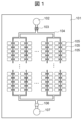
- FIG. 1 is a configuration diagram of a sample solution separation device 101 according to a first embodiment.
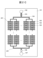
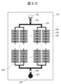
- 1 is a diagram showing a state in which a sample solution 201 and a separation liquid 202 are introduced into a sample solution separation device 101 according to Example 1.
- FIG. 1 is a diagram showing a state in which a sample solution 201 and a separation liquid 202 are introduced into a sample solution separation device 101 according to Example 1.
- FIG. 1 is a diagram showing a state in which a sample solution 201 and a separation liquid 202 are introduced into a sample solution separation device 101 according to Example 1.
- FIG. 1 is a diagram showing a state in which a sample solution 201 and a separation liquid 202 are introduced into a sample solution separation device 101 according to Example 1.
- FIG. 1 is a diagram showing a state in which a sample solution 201 and a separation liquid 202 are introduced into a sample solution separation device 101 according to Example 1.
- FIG. 1 is a diagram showing a state in which a sample solution 201 and
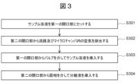
- FIG. 1 is a flow diagram when a sample solution 201 and a separation liquid 202 are introduced into the sample solution separation device 101 according to Example 1, and the sample solution 201 is separated into a microchamber 105.
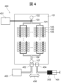
- FIG. FIG. 4 is a configuration diagram of a sample solution separation system 400 that separates and introduces a sample solution 201 to a sample solution separation device 101 according to the first embodiment.
- FIG. 5 is a configuration diagram of a sample solution separation device 501 according to a second embodiment.
- FIG. 6 is a top view of a sample solution separation device 601 according to a third embodiment.
- FIG. 11 is a side view of a sample solution separation device 601 according to a third embodiment.
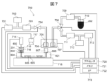
- FIG. 7 is a configuration diagram of a sample solution separation system 700 that separates and introduces a sample solution 201 into a sample solution separation device 601 according to a third embodiment.
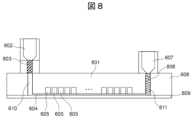
- FIG. 11 is a configuration diagram of a sample solution separation device 801 according to a fourth embodiment.
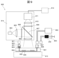
- FIG. 13 is a configuration diagram of a digital PCR system 900 according to a fifth embodiment.
- FIG. 13 is an operation flow diagram of the digital PCR system 900 according to the fifth embodiment.
- Example 1 A sample solution separation device 101 according to Example 1 will be described with reference to Fig. 1 to Fig. 4.
- Fig. 1 is a configuration diagram of the sample solution separation device 101 according to Example 1.
- the sample solution separation device 101 is a device that separates and stores a sample solution in a plurality of microchambers 105.
- the sample solution separation device 101 includes a first opening 102, a valve 103, a flow path 104, a plurality of microchambers 105, a solid phase 106, and a second opening 107.
- the flow path 104 is connected to the first opening 102 via the valve 103.
- a plurality of microchambers 105 are connected to the flow path 104.
- the flow path 104 is also connected to the second opening 107 via the solid phase 106. That is, the flow path 104 connects the first opening 102, the plurality of microchambers 105, and the second opening 107.
- the first opening 102 is an inlet for the sample solution to enter the flow path 104.
- the valve 103 is provided between the first opening 102 and the multiple microchambers 105.
- the second opening 107 is an inlet to the flow path 104 of the separation liquid that separates the multiple microchambers 105 in which the sample solution is contained. This second opening 107 is provided on the opposite side of the first opening 102, sandwiching the multiple microchambers 105 between them.
- the solid phase 106 is provided between the second opening 107 and the multiple microchambers 105.
- the solid phase 106 is breathable, water repellent to the sample solution, and permeable to the separation liquid.
- FIGS. 2A to 2D are diagrams showing the introduction of a sample solution 201 and a separation liquid 202 into the sample solution separation device 101 according to Example 1.
- the sample solution 201 is introduced into the first opening 102.
- the valve 103 is closed (FIG. 2A).
- the air inside the flow channel 104 and the microchamber 105 is degassed from the second opening 107 through the solid phase 106.
- the flow channel 104 and the microchamber 105 are put into a vacuum state.
- the solid phase 106 is a solid that is breathable, hydrophobic, and lipophilic.
- the breathability of the solid phase 106 allows air to pass through, and as described above, the flow path 104 and the microchamber 105 can be placed in a vacuum state.
- the hydrophobicity of the solid phase 106 repels aqueous solutions such as the sample solution 201, preventing the sample solution 201 from passing through.
- the sample solution 201 drawn into the flow channel 104 stops when it reaches the solid phase 106. Since the inside of the microchamber 105 is in a vacuum state, the sample solution 201 continues to be drawn in. Then, the inside of the microchamber 105 becomes filled with the sample solution 201 ( Figure 2C).
- the separation liquid 202 used to separate the multiple microchambers 105 containing the sample solution 201 is a liquid (e.g., oil) that has physical properties that make it immiscible with the sample solution 201.
- the solid phase 106 is lipophilic, allowing it to pass through the separation liquid 202.
- the sample solution 201 in the flow channel 104 is replaced with the separation liquid 202.
- the separation liquid 202 is introduced from the second opening 107. Since the solid phase 106 is lipophilic and has the property of passing the separation liquid 202, the separation liquid 202 is introduced from the second opening 107 through the solid phase 106 into the flow channel 104.
- the sample solution 201 in the flow channel 104 is pushed back toward the first opening 102, and the flow channel 104 is filled with the separation liquid 202 ( Figure 2D). At this time, the sample solution 201 remains in the microchamber 105, so the sample solution 201 in the multiple microchambers 105 is separated by the separation liquid 202 in the flow channel 104.
- the solid phase 106 that is breathable, hydrophobic, and lipophilic, it is possible to remove air from within the flow channel 104 and the microchamber 105, and to stop the sample solution 201 at the position of the solid phase 106.
- the solid phase 106 can introduce the separation liquid 202 into the flow channel 104 and divide and encapsulate the sample solution 201 within the microchamber 105.
- FIG. 3 is a flow diagram showing the process of introducing a sample solution 201 and a separation liquid 202 into the sample solution separation device 101 according to the first embodiment, and separating the sample solution 201 into the microchamber 105.
- the sample solution 201 is placed in the first opening 102 (S301). At this time, the valve 103 closes the flow path 104.
- the pump 403 (see FIG. 4) connected to the second opening 107 is driven, and the air in the flow channel 104 and the multiple microchambers 105 is discharged through the solid phase 106 and the second opening 107 (S302). As a result, the flow channel 104 and the multiple microchambers 105 are placed in a vacuum state.
- the valve 103 opens the flow path 104, and the sample solution 201 is introduced from the first opening 102 through the valve 103 into the flow path 104 and the multiple microchambers 105 (S303).
- the pump 405 (see FIG. 4) connected to the second opening 107 is driven, and the separation liquid 202 is introduced into the flow path 104 through the second opening 107 and the solid phase 106 (S304).
- the sample solution 201 in the flow path 104 is pushed back toward the first opening 102 by the separation liquid 202, and the sample solution 201 in the flow path 104 is replaced by the separation liquid 202, and the multiple microchambers 105 are separated by the separation liquid 202.
- the valve 103 may be closed to prevent the sample solution 201 in the multiple microchambers 105 and the separation liquid 202 in the flow path 104 from moving.
- FIG. 4 is a configuration diagram of a sample solution separation system 400 that separates and introduces a sample solution 201 into a sample solution separation device 101 according to the first embodiment.
- the sample solution separation system 400 includes a valve control mechanism 401, an opening contact portion 402, a pump 403, an opening contact portion 404, a pump 405, a moving mechanism 406, and the sample solution separation device 101.
- the valve control mechanism 401 (valve control means) controls the opening and closing of the valve 103.
- the valve control mechanism 401 changes the valve 103 from a closed state to an open state.
- the opening contact portion 402 is connected to the second opening 107 of the sample solution separation device 101.
- the opening contact portion 402 is also connected to a pump 403 that draws a vacuum in the flow path 104 and the multiple microchambers 105.
- the movement mechanism 406 moves the opening contact portion 402 to connect it to the second opening 107 when drawing a vacuum in the flow path 104 and the multiple microchambers 105.
- the pump 403 degass the air in the flow path 104 and the microchambers 105 through the second opening 107 and the solid phase 106, and draws a vacuum in the flow path 104 and the multiple microchambers 105.
- the opening contact portion 404 is connected to the second opening 107 of the sample solution separation device 101.
- the opening contact portion 404 is also connected to a pump 405 that introduces the separation liquid 202 into the flow path 104.
- the moving mechanism 406 (switching means) connects the opening contact part 402 to the second opening 107 when degassing the flow path 104 and the multiple microchambers 105.
- the moving mechanism 406 also moves the opening contact part 404 to connect it to the second opening 107 when introducing the separation liquid 202 into the flow path 104. In other words, the moving mechanism 406 switches the connection destination of the second opening 107 to the pump 403 or the pump 405.
- the pump 405 (separation liquid introduction means) introduces the separation liquid 202 from the second opening 107 through the solid phase 106 into the flow path 104.
- the pump 403 used to draw the vacuum is a pump that can reduce the pressure from atmospheric pressure to, for example, about 5 kPa to 0.01 kPa. If the degree of vacuum is high, more air can be expelled from the microchamber 105, and more sample solution 201 can be put in.
- the pump 405 for introducing the separation liquid 202 may be, for example, a syringe pump.
- the syringe pump pushes out the separation liquid 202 that has been installed in advance, and introduces the separation liquid 202 into the flow path 104.
- the pump 405 may be one that sucks up the separation liquid 202 in a container that has been installed in advance, and pushes the aspirated separation liquid 202 into the flow path 104.
- the pump 405 may be one that pressurizes the separation liquid 202 to introduce it into the flow path, and may be, for example, a constant volume discharge pump, a diaphragm pump, or a rotary pump. By pressurizing the separation liquid 202 when introducing it into the flow path 104, it is possible to push the separation liquid 202 in even when there is resistance from the solid phase 106 or flow path resistance.
- the solid phase 106 is a porous membrane.
- the solid phase 106 is made of PTFE (polytetrafluoroethylene).
- the solid phase 106 is porous and breathable, allowing air to pass through, is water-repellent, allowing the sample solution 201 to stop, and is lipophilic, allowing the separation liquid 202 to pass through.
- the solid phase 106 may also be made of PFA (perfluoroalkoxyalkylene), FEP (fluoroethylenepropylene), ETFE (ethylenetetrafluoroethylene), or a fluorine-based water-repellent membrane, a silicon-based water-repellent membrane, a polymer-based water-repellent membrane, or a nanoporous membrane.
- the solid phase 106 does not have to be a membrane, and may be made of hydrophobic beads packed into the flow path 104.
- the beads are hydrophobic, and can repel the sample solution 201 and stop it.
- As the porous membrane a hydrophobic membrane with a contact angle with water of, for example, 80 degrees or more may be used.
- the solid phase 106 is made of a material that is lipophilic and allows the separation liquid 202 to permeate and pass through so that the separation liquid 202 can pass through.
- Non-Patent Document 1 a valve was used instead of the solid phase 106, as in the method disclosed in, for example, Non-Patent Document 1.
- the sample solution can be stopped by closing the valve, and air can be removed or a separation liquid can be introduced by opening the valve.
- the valve is a pinch valve that crushes the tube, a volume is required for the part from the flow path to the tube and for the sample solution to pass through the tube.
- the sample solution remaining in this tube cannot be used for measurement, and becomes a dead volume. This dead volume reduces the amount of measurable target DNA, leading to a decrease in detection sensitivity.
- the solid phase 106 of Example 1 the solid phase 106 can be placed near the microchamber 105, and the dead volume of the sample solution 201 can be reduced.
- the solid phase 106 of Example 1 can be mounted on the flow path 104, so that dead volume such as that of a valve can be suppressed.
- the sample solution 201 remaining in the flow path 104 can become dead volume, the volume of the sample solution 201 remaining in the flow path 104 can be minimized by designing and processing the cross-sectional area of the flow path 104 to be small, and the dead volume of the sample solution 201 can be reduced.
- the valve 103 is used before the sample solution 201 is introduced into the flow path 104.
- the valve 103 is closed during vacuuming and is open when the sample solution 201 is introduced.
- a one-time valve that is opened only once when the sample solution 201 is introduced into the flow path 104 can be used as the valve 103.
- a resin film is used as the valve, which is normally closed and is opened by breaking the film when the sample solution 201 is introduced. In this way, it is possible to provide a low-cost and small device.
- the valve 103 may be an electromagnetic valve or a pinch valve that crushes a tube.
- the separation liquid 202 a liquid having physical properties that are not miscible with the sample solution 201 is used.
- the separation liquid 202 can be an oil such as silicone oil or mineral oil, paraffin wax, or a photocurable resin.
- the separation liquid 202 may be a photocurable resin.
- the photocurable resin is introduced in a liquid state into the flow path 104.
- the photocurable resin is then solidified by irradiation with light such as ultraviolet light, and the sample solution 201 can be separated and sealed in the multiple microchambers 105 in which it is contained.
- multiple types of separation liquids may be used instead of one type.
- the photocurable resin and oil are introduced in this order from the second opening 107.
- the photocurable resin reaches the vicinity of the valve 103, and the flow path 104 is filled with oil.
- the photocurable resin is then hardened to seal the end of the flow path 104 with the photocurable resin, and the microchambers 105 are separated by oil.
- the sample solution 201 is, for example, a solution containing the DNA to be measured, polymerase, buffer, primers, and probes.
- the volume of the solution is adjusted to about 10 ⁇ L to about 50 ⁇ L.
- Example 1 the dead volume of the sample solution 201 can be reduced compared to a conventional configuration in which valves are used on both sides of the flow path. Therefore, most of the prepared sample solution 201 can be used for measurement, enabling highly sensitive detection.
- another liquid such as oil may be introduced in succession to the sample solution 201.
- another liquid such as oil
- This allows the inside of the flow channel 104 to be filled with separation liquid such as oil, so that the dead volume of the sample solution 201 in the flow channel 104 can be further reduced.
- the separation liquid 202 is introduced, the liquid pushed back into the first opening 102 becomes oil (separation liquid) and acts as a lid, making it possible to prevent the nucleic acid in the sample solution 201 from diffusing into the atmosphere.
- the sample solution separation device 101 in which the sample solution 201 is separated and introduced into the multiple microchambers 105 undergoes a PCR thermal cycle.
- the target DNA is amplified by PCR in the multiple microchambers 105 through the thermal cycle.
- the thermal cycle is set, for example, at a high temperature of 95°C for 20 seconds and a low temperature of 60°C for 40 seconds, with the double strand dissociated at the high temperature and annealed and extended at the low temperature, resulting in PCR amplification.
- the target DNA that has been separated and introduced into the multiple microchambers 105 can be detected by measuring the fluorescence of the amplified product.
- the volume of the microchambers 105 is, for example, about several pL to several nL, and the number of microchambers 105 is about several thousand to several million.
- the target DNA is divided among many microchambers 105, thereby reducing the amount of background DNA and enabling the target DNA to be detected with high sensitivity.
- the opening contact portion 402 and the opening contact portion 404 are switched using the moving mechanism 406 (switching means), but the flow path may also be switched using an electromagnetic valve or the like.
- the microchambers 105 and the flow channels 104 are connected by a thin connecting flow channel that branches off from the main flow channel.
- This thin connecting flow channel robustly separates the multiple microchambers 105.
- the connecting flow channel has a smaller flow channel cross-sectional area than the main flow channel. Also, since the microchambers 105 beyond the connecting flow channel are filled with the sample solution 201, the separation liquid 202 does not enter the microchambers 105 from the connecting flow channel, but flows through the main flow channel.
- the sample solution 201 becomes droplets in the microchambers 105, and the multiple microchambers 105 are separated by the separation liquid 202.
- the separation liquid 202 does not enter the microchambers 105 but passes through the channel 104, allowing the sample solution 201 to be separated.
- FIG. 5 is a configuration diagram of a sample solution separation device 501 according to a second embodiment.
- the sample solution separation device 501 includes a first opening 102, a valve 103, a flow channel 104, a plurality of microchambers 105, a plurality of solid phases 506a to 506d, and a second opening 107. Note that the same description as in the first embodiment will be omitted as appropriate.
- the flow channel 104 is branched to connect to a large number of microchambers 105.
- a plurality of branch flow channels 104a to 104d branched from the main flow channel are connected to a large number of microchambers 105, and then merge again and are connected to the second opening 107.
- the solid phases 501a to 501d that allow air to pass, stop the sample solution 201, and allow the separation liquid 202 to pass can be installed at a plurality of locations between the microchambers 105 and the second opening 107.
- 5, solid phases 501a to 501d are provided in each of a plurality of branch flow paths 104a to 104d of the flow path 104.
- the number of the branch flow paths 104a to 104d and the number of the solid phases 501a to 501d are not limited to four, and may be two to three, or five or more.
- Example 2 by arranging the solid phases 501a to 501d closer to the microchamber 105 than in Example 1, the amount of sample solution 201 remaining in the flow channel 104 can be reduced, and the dead volume of the sample solution 201 can be reduced.
- Example 3 The sample solution separation device 601 of Example 3 will be described with reference to FIGS. 6A, 6B, and 7.
- FIG. 6A is a top view of the sample solution separation device 601 according to Example 3
- FIG. 6B is a side view of the sample solution separation device 601 according to Example 3.
- the sample solution separation device 601 includes a first opening 602, a valve 603, a flow path 604, a plurality of microchambers 605, a solid phase 606, and a second opening 607. Note that the same explanation as in Examples 1 and 2 will be omitted as appropriate.
- the flow path 604 and the microchamber 605 are processed in a substrate 608.
- through-holes 610 and 611 penetrating the substrate 608 are formed.
- the through-hole 610 is connected to the first opening 602 through the valve 603, and the through-hole 611 is connected to the second opening 607 through the solid phase 606.
- the side of the substrate 608 on which the multiple microchambers 605 and the flow channels 604 are formed is sealed with a film 609 .
- the flow path 604 of the sample solution separation device 601 of Example 3 has a horizontal flow path 604a that is connected to multiple microchambers 605 and extends horizontally, and a vertical flow path 604b (through holes 610 and 611) that is connected to the horizontal flow path 604a and extends vertically.
- the solid phase 606 is provided at the upper end of the vertical flow path 604b (through hole 611).
- the material of the substrate 608 or the film 609 is resin, but the present invention is not limited to this.
- the material of the substrate 608 or the film 609 may be COP (cycloolefin polymer) or COC (cycloolefin copolymer), which have low autofluorescence.
- the material of the substrate 608 or the film 609 may be polycarbonate, polypropylene, PMMA (methacrylic resin), or the like.
- a part of the substrate 608 or the film 609 may be a metal such as aluminum, which has high thermal conductivity, or a material such as carbon, which can suppress light reflection.
- the valve 603 is a normally-closed seal arranged to block the through-hole 610, and is a one-time valve that changes from a closed state to an open state when a hole is made.
- a first opening 602 having a volume capable of receiving the sample solution 201 is arranged on the top of this valve 603.
- the solid phase 606 is in the form of a membrane and arranged to block the through-hole 611.
- a second opening 607 having a volume capable of receiving the separation liquid 202 is arranged on the top of the solid phase 606.
- the sample solution separation system 700 includes a vacuum pump 701, a pressure sensor 702, a filter 703, an electromagnetic valve 704, a moving mechanism 705, an opening contact portion 706, an opening contact portion 707, an electromagnetic valve 708, a liquid pump 709, a container 710, a filter 711, a pressure sensor 712, a pressure pump 713, a valve control mechanism 714, an opening cover 715, a light source 717, a temperature regulator 718, a controller 719, and a sample solution separation device 601.
- the sample solution 201 is filled in advance in the first opening 602 and is placed so as to be in contact with the top of the valve 603. At this time, the valve 603 is in a closed state.
- An opening lid 715 is provided on the first opening 602.
- a pointed part 716 that has a sharp tip and can break the seal (valve 603) is provided on the inside of the upper surface of the opening lid 715.
- the upper surface of the opening lid 715 is made of an elastic material, such as an elastomer or rubber.
- the second opening 607 of the sample solution separation device 601 and the opening contact part 706 are connected by controlling the moving mechanism 705 (switching means).
- the solenoid valve 704 connects or disconnects the vacuum pump 701 and the opening contact part 706.
- the vacuum pump 701 evacuates the flow path 604 and the multiple microchambers 605 of the sample solution separation device 601.
- the valve control mechanism 714 (valve control means) presses the upper part of the opening lid 715, causing the pointed part 716 to break the valve 603. This causes the valve 603 to be in an open state.
- the valve 603 is formed of a thin film seal such as aluminum or resin, and can be broken by the pointed part 716. Because the flow channel 604 and the multiple microchambers 605 are depressurized, the sample solution 201 is drawn into the flow channel 604 and the multiple microchambers 605, and the flow channel 604 and the multiple microchambers 605 are filled with the sample solution 201. Because the solid phase 606 is water repellent, the sample solution 201 passing through the flow channel 604 stops at the solid phase 606.
- the inside of the flow channel 604 and the microchambers 605 can be negatively pressurized by the vacuum pump 701 until the tip of the sample solution 201 reaches the solid phase 606, and the degree of vacuum can be increased.
- the solenoid valve 704 is used to seal the flow path 604, connect the vacuum pump 701 to the opening contact part 706, and open to the atmosphere.
- the flow path 604 of the sample solution separation device 601 is opened to atmospheric pressure.
- the movement mechanism 705 then connects the opening contact part 707 to the second opening 607.
- the solenoid valve 708 connects the opening contact part 707 to the liquid pump 709.
- the liquid pump 709 sucks the separation liquid 202 placed in advance in the container 710 and discharges it toward the opening contact part 707.
- the separation liquid 202 is introduced into the flow path 604 through the second opening 607 and the solid phase 606.
- the solenoid valve 708 switches the connection of the second opening 607 from the liquid pump 709 to the pressure pump 713.
- the pressure pump 713 pressurizes the separation liquid 202 and pushes it into the flow path 604.
- the pressure pump 713 introduces the separation liquid 202 into the flow path 604 by pressurizing it with a pressure that exceeds the flow path resistance of the flow path 604 and the resistance when passing through the solid phase 606.
- the pressure when pressurizing is determined by the separation liquid 202, the size of the flow path 604, the properties of the solid phase 606, etc., and is, for example, about 10 kPa to 200 kPa.
- the sample solution 201 in the flow path 604 is pushed back to the first opening 602 side, and the flow path 604 is filled with the separation liquid 202. In this way, the sample solution 201 remains in each microchamber 605 and is separated by the separation liquid 202. In addition, by applying pressure to introduce the separation liquid 202 into the flow path 604, the expansion of any air bubbles remaining for some reason can be suppressed and the separation liquid 202 can be introduced into the flow path 604.
- the separation liquid 202 may also be a photocurable resin.
- a photocurable resin that is not miscible with the sample solution 201, the sample solution 201 can be separated into each microchamber 605.
- the photocurable resin is cured using the light source 717. This allows the sample solution 201 to be sealed within the microchamber 605.
- the temperature of the sample solution separation device 601 can also be controlled using the temperature regulator 718.
- the viscosity of the sample solution 201 or separation liquid 202 decreases when the temperature is high. Therefore, by heating the sample solution 201 or separation liquid 202 compared to room temperature, the viscosity of the sample solution 201 or separation liquid 202 decreases, making it easier for the sample solution 201 or separation liquid 202 to enter the flow path 604 or microchamber 605. This makes it possible to shorten the time required to introduce the solutions (sample solution 201 and separation liquid 202) and to robustly introduce the sample solution 201 into all microchambers 605.
- the pressure when the vacuum pump 701 is drawing a vacuum is monitored and controlled by the pressure sensor 702.
- the pressure when the pressure pump 713 is applying pressure is monitored and controlled by the pressure sensor 712.
- Filters 703 and 711 also prevent dust and other particles from getting into the sample solution 201 and the separation solution 202.
- the series of operations described above is controlled by a controller 719.
- the controller 719 has a processor 720, a memory 721, and an interface 722.
- the processor 720 executes various programs on the memory 721, and outputs control signals for controlling the operations described above via the interface 722.
- the valve control mechanism 714 is, for example, a solenoid that moves when a current flows through it, thereby opening the valve 603.
- the movement mechanism 705 is, for example, a two-axis motor drive mechanism with horizontal and vertical axes.
- the solid phase 606 which is breathable, hydrophobic, and lipophilic, it is possible to control the vacuuming of the flow path 604, the stopping of the sample solution 201, and the passage of the separation liquid 202 without using a valve. In addition, it is possible to place the solid phase 606 close to the microchamber 605, so that the sample solution 201 can be divided and placed in the microchamber 605 without wasting the sample solution 201.
- valve 603 By using a one-time valve configured to make a hole in a thin film as the valve 603, a valve with a simple configuration can be implemented. Since the valve 603 comes into contact with the sample solution 201, it needs to be disposable to prevent carryover, so a one-time valve is useful. Also, since the valve 603 has a simple configuration, it can be provided at low cost. Also, by using a photocurable resin as the separation liquid 202 and putting it in the flow path 604 in liquid form and then solidifying it, the microchamber 605 can be sealed. This eliminates the need to close the first opening 602 and the second opening 607, making it possible to simplify the configuration.
- the valve 603 may be perforated with a pipette tip.
- the sample solution separation device 601 according to the third embodiment may also be applied to an automated system that is connected to sample pretreatment, such as nucleic acid extraction, reagent mixing, and dispensing.
- sample pretreatment such as nucleic acid extraction, reagent mixing, and dispensing.
- a specimen collected in a blood collection tube is centrifuged to extract plasma, and the plasma is purified to extract nucleic acid in the plasma.
- the nucleic acid is mixed with a reagent, and the target nucleic acid is detected by digital PCR.
- a dispensing system that aspirates and discharges the mixed sample solution with a pipette tip is used to inject the sample solution 201 into the first opening 602.
- the valve may be broken with the tip of the pipette tip, and the sample solution 201 may be introduced into the flow path.
- the dead volume of the sample solution 201 can be further reduced. Specifically, after the sample solution 201 is introduced into the microchamber 605 by negative pressure, the oil (separation liquid) continuously enters the flow channel 604, so that the sample solution 201 remaining in the flow channel 604 can be reduced. In this state, by introducing the separation liquid 202 from the second opening 607 in the opposite direction to the sample solution 201, the sample solution 201 in the flow channel 604 can be completely replaced with the separation liquid 202, and the multiple microchambers 605 can be separated.
- the oil (separation liquid) introduced continuously with the sample solution 201 plays the role of a lid that prevents the nucleic acid in the sample solution 201 from becoming an aerosol and being released into the atmosphere. By doing so, the dead volume of the sample solution 201 can be further reduced compared to the case where only the sample solution 201 is introduced from the first opening 602.
- the separation liquid 202 in the container 710 is introduced into the flow path 604 through the second opening 607, but the present invention is not limited to this.
- the separation liquid 202 may be filled in the sample solution separation device 601 in advance, and the separation liquid 202 filled in the sample solution separation device 601 may be introduced into the flow path 604.
- FIG. 8 is a configuration diagram of a sample solution separation device 801 according to a fourth embodiment.
- the solid phase 806 of the sample solution separation device 801 according to the fourth embodiment is a plurality of particles having air permeability, hydrophobicity, and lipophilicity.
- the plurality of particles are packed in the through-hole 611 (vertical flow channel) to form the solid phase 806.
- the particles are, for example, beads having a size of 0.1 ⁇ m to 10 ⁇ m.
- the particles are easier to introduce into the flow channel 604 than a membrane.
- air can pass between the particles, so that vacuum drawing is possible.
- the particles are water repellent, so that the sample solution 201 can be stopped.
- the particles are lipophilic, so that they can pass through the separation liquid 202.
- the valve 603 is a one-time valve, but the present invention is not limited to this.
- the valve 803 of the sample solution separation device 800 according to the fourth embodiment may be an elastic tube. The tube is stretched to connect with the through-hole 610 of the substrate 608 to form the valve 803.
- the valve 803 is a silicone tube. The silicone tube is compressed to form a pinch valve that stops the flow in the tube. By using the pinch valve, it can be opened and closed multiple times. The valve 803 is closed when drawing a vacuum, and the valve 803 is opened when introducing the sample solution 201. After the introduction of the separation liquid 202, the valve 803 is closed to seal the sample solution 201 and the separation liquid 202.
- Example 5 The sample solution separation device of the present invention can be used for digital PCR.
- Fig. 9 is a configuration diagram of a digital PCR system 900 according to Example 5.
- the digital PCR system 900 includes a sample solution separation device 601, a valve control mechanism 901, a pump 902, a liquid pump 903, a temperature regulator 913, an optical system 914 (measurement means), and an analysis unit 912.
- the optical system 914 includes a light source 904, a lens 905, a lens 908, a lens 910, a bandpass filter 906, a bandpass filter 909, a dichroic mirror 907, and a CMOS sensor 911.
- the sample solution 201 is placed in the sample solution separation device 601 through the first opening 602.
- the air in the flow path 604 and the microchamber 605 is degassed through the second opening 607, creating a negative pressure.
- the valve control mechanism 901 opens the valve 603, and the sample solution 201 is introduced into the flow path 604 and the microchamber 605.
- the separation liquid 202 is introduced into the flow path 604 via the second opening 607. In this way, the sample solution 201 can be separated and introduced into multiple microchambers 605.
- the sample solution 201 is a PCR reaction solution containing the DNA to be detected, polymerase, buffer, primers, and probe.
- a thermal cycle process is performed on a device in which the sample solution 201, which is the PCR reaction solution, is separated and placed in a number of microchambers 605.
- the temperature regulator 913 is controlled to a temperature range in which denaturation, annealing, and extension are performed.
- the temperature regulator 913 is composed of a heater, Peltier element, etc., but the present invention is not limited to this. If the DNA to be measured is present in the microchambers 605, the target DNA is amplified by the thermal cycle process.
- the optical system 914 measures the target nucleic acid in the PCR-amplified sample solution 201.
- the light emitted from the light source 904 is collimated by the lens 905, the bandpass filter 906 transmits light of a specific wavelength, is reflected by the dichroic mirror 907, passes through the lens 908, and is irradiated onto the sample solution separation device 601.
- the fluorescence from the microchamber 605 of the sample solution separation device 601 passes through the lens 908, the dichroic mirror 907, the bandpass filter 909, and the lens 910, and is imaged by the CMOS sensor 911.
- the analysis unit 912 performs an analysis based on the image captured by the CMOS sensor 911, and detects the target DNA in each microchamber.
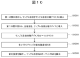
- FIG. 10 is an operational flow diagram of the digital PCR system 900 according to the fifth embodiment.
- the valve control mechanism 901 opens the valve 603 and introduces the sample solution 201 set in the first opening 602 into the sample solution separation device 601 (S1001).
- the liquid pump 903 introduces the separation liquid 202 from the second opening 607 into the sample solution separation device 601 (S1002). This causes the sample solution 201 to be separated and introduced into the multiple microchambers 605.
- the temperature regulator 913 subjects the sample solution separation device 601 to a thermal cycle (S1003).
- the optical system 914 irradiates the sample solution separation device 601 with light and measures the fluorescence intensity of each microchamber 605 (S1004).
- the analysis unit 915 analyzes the fluorescence intensity measured by the optical system 914 to detect the target DNA in the sample solution 201 (S1005).
- the sample solution 201 and the separation liquid 202 may be heated. This changes the viscosity of the sample solution 201 and the separation liquid 202, making it easier to introduce them into the flow path 604. In addition, the time required to introduce the sample solution 201 and the separation liquid 202 can be shortened.
- the temperature regulator that heats the sample solution 201 and the separation liquid 202 may be the temperature regulator 913 that performs a thermal cycle, or may be a temperature regulator separate from the temperature regulator 913.
- Asymmetric PCR can be performed by varying the concentrations of the forward primer and reverse primer in the PCR reaction solution, so that one of the single-stranded DNAs is amplified more in the amplified products. In this way, single-stranded DNA is detected using a molecular beacon.
- the temperature of the sample solution separation device is controlled during fluorescence measurement, and melting curve analysis is performed. Fluorescence measurement is performed in multiple colors using multiple filters. Highly multiplexed and highly sensitive measurements can be achieved by identifying the target DNA using the fluorescence color, fluorescence intensity, and melting temperature of each microchamber.
- sample solution separation method a method for separating the sample solution 201 into a plurality of microchambers 105 will be described.
- the sample solution separation method includes the following steps: Preparing the above-mentioned sample solution separation device 101; Degassing the air in the plurality of microchambers 105 and the flow channel 104 via the solid phase 106; The method includes opening a valve 103 and introducing a sample solution 201 from a first opening 102 into the multiple microchambers 105 and the flow channel 104, and introducing a separation liquid 202 from a second opening 107 into the flow channel 104 via the solid phase 106.
- the sample solution separation device 101 to be prepared may be the sample solution separation device 501, 601 or 801.
- the sample solution separation method is as follows: carrying out a thermal cycle of PCR (polymerase chain reaction) on the sample solution separation device 101 in which the sample solution 201 is separated into the multiple microchambers 105; The method further includes measuring the fluorescence intensity of the plurality of microchambers 105, and analyzing the fluorescence intensity to detect the target DNA in the sample solution 201.
- PCR polymerase chain reaction
- introducing the sample solution 201 from the first opening 102 into the multiple microchambers 105 and the flow path 104 includes introducing the sample solution 201 and oil (separation liquid) following the sample solution 201 from the first opening 102.
- the present disclosure is not limited to the above-described embodiments, and includes various modified examples.
- the above-described embodiments have been described in detail to clearly explain the present disclosure, and are not necessarily limited to those having all of the configurations described.
- it is possible to replace a part of the configuration of one embodiment with the configuration of another embodiment and it is also possible to add the configuration of another embodiment to the configuration of one embodiment.
- a separation liquid is used to separate the multiple microchambers 105, but the present invention is not limited to this, and a separation gas may also be used.
- the solid phase only needs to have physical properties that allow the separation gas to pass through.
Landscapes
- Health & Medical Sciences (AREA)
- Life Sciences & Earth Sciences (AREA)
- Chemical & Material Sciences (AREA)
- Engineering & Computer Science (AREA)
- Physics & Mathematics (AREA)
- Molecular Biology (AREA)
- General Health & Medical Sciences (AREA)
- Hematology (AREA)
- Analytical Chemistry (AREA)
- Biomedical Technology (AREA)
- Biophysics (AREA)
- Dispersion Chemistry (AREA)
- Chemical Kinetics & Catalysis (AREA)
- Clinical Laboratory Science (AREA)
- Urology & Nephrology (AREA)
- Food Science & Technology (AREA)
- Medicinal Chemistry (AREA)
- Biochemistry (AREA)
- General Physics & Mathematics (AREA)
- Immunology (AREA)
- Pathology (AREA)
- Automatic Analysis And Handling Materials Therefor (AREA)
Abstract
Description
その他の課題と新規な特徴は、本明細書の記述及び添付図面から明らかになるであろう。
実施例1に係るサンプル溶液分離デバイス101について、図1~図4を用いて説明する。図1は、実施例1に係るサンプル溶液分離デバイス101の構成図である。サンプル溶液分離デバイス101は、サンプル溶液を複数のマイクロチャンバ105に分離して収容するデバイスである。サンプル溶液分離デバイス101は、第一の開口部102、バルブ103、流路104、複数のマイクロチャンバ105、固相106、及び第二の開口部107を備える。
実施例1では、固相106が、流路104の一か所に配置されている例を説明したが、本発明は、これに限るものではない。図5は、実施例2に係るサンプル溶液分離デバイス501の構成図である。サンプル溶液分離デバイス501は、第一の開口部102、バルブ103、流路104、複数のマイクロチャンバ105、複数の固相506a~506d、及び第二の開口部107を備える。なお、実施例1と同様の説明は適宜省略する。流路104は、多数のマイクロチャンバ105に接続するため分岐される。メイン流路から分岐した複数の分岐流路104a~104dは、多数のマイクロチャンバ105に接続された後に、再度合流し、第二の開口部107に接続される。空気を通過させ、サンプル溶液201を停止させ、且つ分離液202を通過させる固相501a~501dは、マイクロチャンバ105と第二の開口部107の間の複数個所に設置することができる。図5の例では、流路104の複数の分岐流路104a~104dのそれぞれに、固相501a~501dが設けられる。複数の分岐流路104a~104dの個数及び固相501a~501dの個数は、4個に限定されず、2~3個であってもよいし、5個以上であってもよい。
実施例3のサンプル溶液分離デバイス601について、図6A、図6B及び図7を用いて説明する。図6Aは、実施例3に係るサンプル溶液分離デバイス601の上面図であり、図6Bは、実施例3に係るサンプル溶液分離デバイス601の側面図である。図6A及び図6Bに示すように、サンプル溶液分離デバイス601は、第一の開口部602、バルブ603、流路604、複数のマイクロチャンバ605、固相606、及び第二の開口部607を備える。なお、実施例1及び実施例2と同様の説明は適宜省略する。流路604及びマイクロチャンバ605は、基板608に加工される。また、流路604の一方端及び他方端には、基板608を貫通した貫通孔610及び611が形成される。貫通孔610は、バルブ603を通じて第一の開口部602と接続され、貫通孔611は、固相606を通じて第二の開口部607に接続される。また、基板608の複数のマイクロチャンバ605及び流路604を加工した側は、フィルム609により封止される。
上記した実施例3では、基板608の貫通孔611の上端部に薄膜の固相606を設置したが、本発明はこれに限るものではない。図8は、実施例4に係るサンプル溶液分離デバイス801の構成図である。実施例4に係るサンプル溶液分離デバイス801の固相806は、通気性、疎水性、親油性を有する複数の微粒子である。複数の微粒子は、貫通孔611(垂直方向流路)に詰められて、固相806を形成する。微粒子は、例えば、0.1μmから10μmのサイズを持つビーズである。微粒子は、膜よりも流路604内へと導入しやすい。また、微粒子の間を空気が通過することができるため、真空引きが可能となる。また、微粒子は、撥水性を有するため、サンプル溶液201を停止することができる。また、微粒子は、親油性を有するため、分離液202を通過することができる。
本発明のサンプル溶液分離デバイスは、デジタルPCRに用いることができる。図9は、実施例5に係るデジタルPCRシステム900の構成図である。デジタルPCRシステム900(サンプル溶液分離システム)は、サンプル溶液分離デバイス601、バルブ制御機構901、ポンプ902、液体ポンプ903、温調器913、光学系914(計測手段)、及び解析部912を備える。光学系914は、光源904、レンズ905、レンズ908、レンズ910、バンドパスフィルタ906、バンドパスフィルタ909、ダイクロイックミラー907、及びCMOSセンサ911を有する。
ここで、サンプル溶液201を複数のマイクロチャンバ105に分離する方法を説明する。サンプル溶液分離方法は、
上記したサンプル溶液分離デバイス101を準備こと、
固相106を介して、複数のマイクロチャンバ105及び流路104内の空気を脱気すること、
バルブ103を開放し、第一の開口部102からサンプル溶液201を複数のマイクロチャンバ105及び流路104に導入すること、及び
第二の開口部107から固相106を介して分離液202を流路104に導入すること、を有する。
なお、準備するサンプル溶液分離デバイス101は、サンプル溶液分離デバイス501、601又は801であってもよい。
複数のマイクロチャンバ105にサンプル溶液201が分離されたサンプル溶液分離デバイス101に対してPCR(ポリメラーゼ連鎖反応)のサーマルサイクルを実施すること、
複数のマイクロチャンバ105の蛍光強度を計測すること、及び
蛍光強度を解析し、サンプル溶液201内のターゲットDNAを検出すること、をさらに有する。
本開示は、前述した実施形態に限定されるものではなく、様々な変形例が含まれる。例えば、前述した実施形態は本開示を分かりやすく説明するために詳細に説明したものであり、必ずしも説明した全ての構成を備えるものに限定されるものではない。また、ある実施形態の構成の一部を他の実施形態の構成に置き換えることが可能であり、また、ある実施形態の構成に他の実施形態の構成を加えることも可能である。また、各実施形態の構成の一部について、他の構成の追加・削除・置換をすることが可能である。
102 第一の開口部
103 バルブ
104 流路
105 マイクロチャンバ
106 固相
107 第二の開口部
201 サンプル溶液
202 分離液
400,700 サンプル溶液分離システム
401 バルブ制御機構
402,404 開口部コンタクト部
403,405 ポンプ
406 移動機構
506a,506b,506c,506d 固相
602 第一の開口部
603 バルブ
604 流路
604a 水平方向流路
604b 垂直方向流路
605 マイクロチャンバ
606 固相
607 第二の開口部
608 基板
609 フィルム
610,611 貫通孔
701 真空ポンプ
702,712 圧力センサ
703,711 フィルタ
704,708 電磁弁
705 移動機構
706,707 開口部コンタクト部
709 液体ポンプ
710 容器
713 加圧ポンプ
714 バルブ制御機構
715 開口部用蓋
716 尖頭部品
717 光源
718 温調器
719 コントローラ
720 プロセッサ
721 メモリ
722 インターフェース
803 バルブ
806 固相
900 デジタルPCRシステム
901 バルブ制御機構
902 ポンプ
903 液体ポンプ
904 光源
905,908、910 レンズ
906,909 バンドパスフィルタ
907 ダイクロイックミラー
911 CMOSセンサ
912 解析部
913 温調器
914 光学系
Claims (16)
- サンプル溶液を分離するサンプル溶液分離デバイスであって、
複数のマイクロチャンバと、
前記複数のマイクロチャンバを接続する流路と、
前記サンプル溶液の前記流路への導入口である第一の開口部と、
前記第一の開口部と前記複数のマイクロチャンバとの間に設けられるバルブと、
前記サンプル溶液が収容される前記複数のマイクロチャンバ間を分離する分離液の流路への導入口であって、前記複数のマイクロチャンバを挟んで前記第一の開口部の反対側に設けられる第二の開口部と、
前記第二の開口部と前記複数のマイクロチャンバとの間に設けられる固相と、を備え、
前記固相は、通気性を有し、前記サンプル溶液に対して撥水性を有し、且つ前記分離液に対して通過性を有する
ことを特徴とするサンプル溶液分離デバイス。 - 前記流路は、前記マイクロチャンバがそれぞれ接続される複数の分岐流路を有し、
前記固相は、前記複数の分岐流路のそれぞれに設けられる
ことを特徴とする請求項1に記載のサンプル溶液分離デバイス。 - 前記流路は、
前記複数のマイクロチャンバが接続され、水平方向に延びる水平方向流路と、
前記水平方向流路に接続され、垂直方向に延びる垂直方向流路と、を有し、
前記固相は、前記垂直方向流路の上端部に設けられる
ことを特徴とする請求項1に記載のサンプル溶液分離デバイス。 - 前記流路は、
前記複数のマイクロチャンバが接続され、水平方向に延びる水平方向流路と、
前記水平方向流路に接続され、垂直方向に延びる垂直方向流路と、を有し、
前記固相は、前記垂直方向流路内に設けられた複数の微粒子である
ことを特徴とする請求項1に記載のサンプル溶液分離デバイス。 - 前記バルブは、前記サンプル溶液を前記流路に導入する際に1度だけ開放されるワンタイムバルブである
ことを特徴とする請求項1に記載のサンプル溶液分離デバイス。 - 前記固相は、前記サンプル溶液に対して撥水性を有し、且つ前記分離液に対して通過性を有する多孔質膜である
ことを特徴とする請求項1に記載にサンプル溶液分離デバイス。 - 前記多孔質膜の材料は、PTFE(ポリテトラフルオロエチレン)である
ことを特徴とする請求項6に記載のサンプル溶液分離デバイス。 - 前記分離液は、光硬化樹脂であって、
前記分離液は、前記流路内で光照射によって硬化する
ことを特徴とする請求項1に記載のサンプル溶液分離デバイス。 - 前記分離液は、前記サンプル溶液と混和しない物性を有するオイルである
ことを特徴する請求項1に記載のサンプル溶液分離デバイス。 - サンプル溶液を分離するサンプル溶液分離デバイスであって、複数のマイクロチャンバと、前記複数のマイクロチャンバを接続する流路と、前記サンプル溶液の前記流路への導入口である第一の開口部と、前記第一の開口部と前記複数のマイクロチャンバとの間に設けられるバルブと、前記サンプル溶液が収容される前記複数のマイクロチャンバ間を分離する分離液の流路への導入口であって、前記複数のマイクロチャンバを挟んで前記第一の開口部の反対側に設けられる第二の開口部と、前記第二の開口部と前記複数のマイクロチャンバとの間に設けられる固相と、を備え、前記固相は、通気性を有し、前記サンプル溶液に対して撥水性を有し、且つ前記分離液に対して通過性を有する、サンプル溶液分離デバイス、
前記複数のマイクロチャンバ及び前記流路内の空気を前記第二の開口部から前記固相を通じて脱気するポンプ、
前記バルブを開放するバルブ制御手段、及び
前記第二の開口部から分離液を導入する分離液導入手段、を有する
ことを特徴とするサンプル溶液分離システム。 - 前記第二の開口部の接続先を前記ポンプ又は前記分離液導入手段に切り替える切替手段、をさらに有する
ことを特徴とする請求項10に記載のサンプル溶液分離システム。 - 前記分離液を加圧して、前記流路に導入する加圧ポンプ、をさらに有する
ことを特徴とする請求項10に記載のサンプル溶液分離システム。 - 前記マイクロチャンバ内でPCR(ポリメラーゼ連鎖反応)が実施された前記サンプル溶液内の対象の核酸を計測する計測手段、をさらに有する
ことを特徴とする請求項10に記載のサンプル溶液分離システム。 - サンプル溶液を分離するサンプル溶液分離デバイスであって、複数のマイクロチャンバと、前記複数のマイクロチャンバを接続する流路と、前記サンプル溶液の前記流路への導入口である第一の開口部と、前記第一の開口部と前記複数のマイクロチャンバとの間に設けられるバルブと、前記サンプル溶液が収容される前記複数のマイクロチャンバ間を分離する分離液の流路への導入口であって、前記複数のマイクロチャンバを挟んで前記第一の開口部の反対側に設けられる第二の開口部と、前記第二の開口部と前記複数のマイクロチャンバとの間に設けられる固相と、を備え、前記固相は、通気性を有し、前記サンプル溶液に対して撥水性を有し、且つ前記分離液に対して通過性を有する、サンプル溶液分離デバイス、を準備すること、
前記固相を介して、前記複数のマイクロチャンバ及び前記流路内の空気を脱気すること、
前記バルブを開放し、前記第一の開口部から前記サンプル溶液を前記複数のマイクロチャンバ及び前記流路に導入すること、及び
前記第二の開口部から前記固相を介して前記分離液を流路に導入すること、を有する
ことを特徴とするサンプル溶液分離方法。 - 前記複数のマイクロチャンバに前記サンプル溶液が分離された前記サンプル溶液分離デバイスに対してPCR(ポリメラーゼ連鎖反応)のサーマルサイクルを実施すること、
前記複数のマイクロチャンバの蛍光強度を計測すること、及び
前記蛍光強度を解析し、前記サンプル溶液内のターゲットDNAを検出すること、をさらに有する
ことを特徴とする請求項14に記載のサンプル溶液分離方法。 - 前記第一の開口部から前記サンプル溶液を前記複数のマイクロチャンバ及び前記流路に導入することは、前記第一の開口部から前記サンプル溶液、及び前記サンプル溶液に続く分離液を導入することを含む
ことを特徴とする請求項14に記載のサンプル溶液分離方法。
Priority Applications (4)
| Application Number | Priority Date | Filing Date | Title |
|---|---|---|---|
| PCT/JP2023/020780 WO2024252453A1 (ja) | 2023-06-05 | 2023-06-05 | サンプル溶液分離デバイス、サンプル溶液分離システム、及びサンプル溶液分離方法 |
| EP23940561.6A EP4722733A1 (en) | 2023-06-05 | 2023-06-05 | Sample solution separation device, sample solution separation system, and sample solution separation method |
| JP2025525430A JP7872896B2 (ja) | 2023-06-05 | 2023-06-05 | サンプル溶液分離デバイス、サンプル溶液分離システム、及びサンプル溶液分離方法 |
| CN202380093761.3A CN120677390A (zh) | 2023-06-05 | 2023-06-05 | 样品溶液分离装置、样品溶液分离系统以及样品溶液分离方法 |
Applications Claiming Priority (1)
| Application Number | Priority Date | Filing Date | Title |
|---|---|---|---|
| PCT/JP2023/020780 WO2024252453A1 (ja) | 2023-06-05 | 2023-06-05 | サンプル溶液分離デバイス、サンプル溶液分離システム、及びサンプル溶液分離方法 |
Publications (1)
| Publication Number | Publication Date |
|---|---|
| WO2024252453A1 true WO2024252453A1 (ja) | 2024-12-12 |
Family
ID=93795232
Family Applications (1)
| Application Number | Title | Priority Date | Filing Date |
|---|---|---|---|
| PCT/JP2023/020780 Ceased WO2024252453A1 (ja) | 2023-06-05 | 2023-06-05 | サンプル溶液分離デバイス、サンプル溶液分離システム、及びサンプル溶液分離方法 |
Country Status (4)
| Country | Link |
|---|---|
| EP (1) | EP4722733A1 (ja) |
| JP (1) | JP7872896B2 (ja) |
| CN (1) | CN120677390A (ja) |
| WO (1) | WO2024252453A1 (ja) |
Citations (6)
| Publication number | Priority date | Publication date | Assignee | Title |
|---|---|---|---|---|
| JP2000508528A (ja) * | 1996-04-03 | 2000-07-11 | ザ パーキン―エルマー コーポレーション | 複数の分析物の検出のためのデバイスおよび方法 |
| JP2006521829A (ja) * | 2003-04-03 | 2006-09-28 | フルイディグム コーポレイション | マイクロ流体装置およびその使用方法 |
| US20100041046A1 (en) * | 2008-08-15 | 2010-02-18 | University Of Washington | Method and apparatus for the discretization and manipulation of sample volumes |
| JP4888773B2 (ja) | 2006-12-07 | 2012-02-29 | セイコーエプソン株式会社 | 液滴吐出装置および液滴吐出方法 |
| JP2014505476A (ja) * | 2011-01-20 | 2014-03-06 | ユニバーシティ オブ ワシントン スルー イッツ センター フォー コマーシャライゼーション | デジタル測定を実施するための方法およびシステム |
| US11305276B2 (en) | 2017-05-24 | 2022-04-19 | Biofire Defense, Llc | Systems and methods for point of use evacuation of an array |
-
2023
- 2023-06-05 EP EP23940561.6A patent/EP4722733A1/en active Pending
- 2023-06-05 JP JP2025525430A patent/JP7872896B2/ja active Active
- 2023-06-05 CN CN202380093761.3A patent/CN120677390A/zh active Pending
- 2023-06-05 WO PCT/JP2023/020780 patent/WO2024252453A1/ja not_active Ceased
Patent Citations (6)
| Publication number | Priority date | Publication date | Assignee | Title |
|---|---|---|---|---|
| JP2000508528A (ja) * | 1996-04-03 | 2000-07-11 | ザ パーキン―エルマー コーポレーション | 複数の分析物の検出のためのデバイスおよび方法 |
| JP2006521829A (ja) * | 2003-04-03 | 2006-09-28 | フルイディグム コーポレイション | マイクロ流体装置およびその使用方法 |
| JP4888773B2 (ja) | 2006-12-07 | 2012-02-29 | セイコーエプソン株式会社 | 液滴吐出装置および液滴吐出方法 |
| US20100041046A1 (en) * | 2008-08-15 | 2010-02-18 | University Of Washington | Method and apparatus for the discretization and manipulation of sample volumes |
| JP2014505476A (ja) * | 2011-01-20 | 2014-03-06 | ユニバーシティ オブ ワシントン スルー イッツ センター フォー コマーシャライゼーション | デジタル測定を実施するための方法およびシステム |
| US11305276B2 (en) | 2017-05-24 | 2022-04-19 | Biofire Defense, Llc | Systems and methods for point of use evacuation of an array |
Non-Patent Citations (2)
| Title |
|---|
| MICROMACHINES, vol. 11, 2020, pages 1025 |
| See also references of EP4722733A1 |
Also Published As
| Publication number | Publication date |
|---|---|
| JP7872896B2 (ja) | 2026-06-10 |
| CN120677390A (zh) | 2025-09-19 |
| JPWO2024252453A1 (ja) | 2024-12-12 |
| EP4722733A1 (en) | 2026-04-08 |
Similar Documents
| Publication | Publication Date | Title |
|---|---|---|
| JP6709319B2 (ja) | Pcr方法 | |
| CN103210079B (zh) | 用于聚合酶链式反应的可增压筒 | |
| EP3401386B1 (en) | Reaction treatment device | |
| KR102041217B1 (ko) | 다-채널 하향 액체 주입 장치, 이를 포함하는 핵산 추출 장치, 및 이를 이용한 핵산 추출 방법 | |
| KR102263837B1 (ko) | 현장진단용 다중 초고속 핵산 추출 및 증폭이 가능한 통합칩 | |
| WO2007052471A1 (ja) | マイクロリアクタおよびそれを用いた送液方法 | |
| CA2799676C (en) | Reaction vessel for pcr device and method of performing pcr | |
| US20210316308A1 (en) | Microfluidic device and method for use thereof for the separation, purification and concentration of components of fluid media | |
| Kim et al. | On-site extraction and purification of bacterial nucleic acids from blood samples using an unpowered microfluidic device | |
| WO2006112498A1 (ja) | 検体を分析するための検査チップおよびマイクロ分析システム | |
| JPWO2019139135A1 (ja) | 反応処理装置 | |
| JP4705504B2 (ja) | マイクロ流体チップ | |
| KR20200031612A (ko) | 개질된 필터 막 및 그 사용 | |
| JP2021035353A (ja) | 増幅反応チャンバーを含むマイクロ流体デバイス | |
| JP2007083191A (ja) | マイクロリアクタ | |
| KR101893114B1 (ko) | 기체 버블 트랩 기능을 갖는 미세 유체 공급소자 | |
| EP4722733A1 (en) | Sample solution separation device, sample solution separation system, and sample solution separation method | |
| CN219239665U (zh) | 一种病毒检测微流控芯片及病毒检测试剂盒 | |
| JP6641032B2 (ja) | 誘電泳動(dep)を用いた標的細胞濃度の改善 | |
| JP2007135504A (ja) | 増幅部位にビーズを保持する核酸検査用マイクロリアクタ | |
| JP4687413B2 (ja) | マイクロチップにおける2種類以上の液体の混合方法およびマイクロ総合分析システム | |
| WO2007055165A1 (ja) | 核酸の分離方法、核酸検査用マイクロリアクタ、核酸検査システム | |
| EP4484962A1 (en) | Test container and nucleic acid test method | |
| CN101213023A (zh) | 流体分析装置和方法 | |
| JP4517909B2 (ja) | マイクロ総合分析システム |
Legal Events
| Date | Code | Title | Description |
|---|---|---|---|
| 121 | Ep: the epo has been informed by wipo that ep was designated in this application |
Ref document number: 23940561 Country of ref document: EP Kind code of ref document: A1 |
|
| ENP | Entry into the national phase |
Ref document number: 2025525430 Country of ref document: JP Kind code of ref document: A |
|
| WWE | Wipo information: entry into national phase |
Ref document number: 2025525430 Country of ref document: JP |
|
| WWE | Wipo information: entry into national phase |
Ref document number: 202380093761.3 Country of ref document: CN |
|
| WWP | Wipo information: published in national office |
Ref document number: 202380093761.3 Country of ref document: CN |
|
| ENP | Entry into the national phase |
Ref document number: 2023940561 Country of ref document: EP Effective date: 20260105 |
|
| WWE | Wipo information: entry into national phase |
Ref document number: 2023940561 Country of ref document: EP |
|
| NENP | Non-entry into the national phase |
Ref country code: DE |
|
| ENP | Entry into the national phase |
Ref document number: 2023940561 Country of ref document: EP Effective date: 20260105 |
|
| ENP | Entry into the national phase |
Ref document number: 2023940561 Country of ref document: EP Effective date: 20260105 |
|
| ENP | Entry into the national phase |
Ref document number: 2023940561 Country of ref document: EP Effective date: 20260105 |
|
| ENP | Entry into the national phase |
Ref document number: 2023940561 Country of ref document: EP Effective date: 20260105 |
|
| ENP | Entry into the national phase |
Ref document number: 2023940561 Country of ref document: EP Effective date: 20260105 |