WO2024252443A1 - 自律移動制御装置、自律移動制御システム、自律移動体、自律移動制御方法、自律移動制御プログラムおよび記録媒体 - Google Patents
自律移動制御装置、自律移動制御システム、自律移動体、自律移動制御方法、自律移動制御プログラムおよび記録媒体 Download PDFInfo
- Publication number
- WO2024252443A1 WO2024252443A1 PCT/JP2023/020752 JP2023020752W WO2024252443A1 WO 2024252443 A1 WO2024252443 A1 WO 2024252443A1 JP 2023020752 W JP2023020752 W JP 2023020752W WO 2024252443 A1 WO2024252443 A1 WO 2024252443A1
- Authority
- WO
- WIPO (PCT)
- Prior art keywords
- marker
- autonomous
- target position
- environment
- map data
- Prior art date
- Legal status (The legal status is an assumption and is not a legal conclusion. Google has not performed a legal analysis and makes no representation as to the accuracy of the status listed.)
- Ceased
Links
Images





Classifications
-
- G—PHYSICS
- G01—MEASURING; TESTING
- G01C—MEASURING DISTANCES, LEVELS OR BEARINGS; SURVEYING; NAVIGATION; GYROSCOPIC INSTRUMENTS; PHOTOGRAMMETRY OR VIDEOGRAMMETRY
- G01C21/00—Navigation; Navigational instruments not provided for in groups G01C1/00 - G01C19/00
- G01C21/20—Instruments for performing navigational calculations
-
- G—PHYSICS
- G08—SIGNALLING
- G08G—TRAFFIC CONTROL SYSTEMS
- G08G1/00—Traffic control systems for road vehicles
-
- G—PHYSICS
- G09—EDUCATION; CRYPTOGRAPHY; DISPLAY; ADVERTISING; SEALS
- G09B—EDUCATIONAL OR DEMONSTRATION APPLIANCES; APPLIANCES FOR TEACHING, OR COMMUNICATING WITH, THE BLIND, DEAF OR MUTE; MODELS; PLANETARIA; GLOBES; MAPS; DIAGRAMS
- G09B29/00—Maps; Plans; Charts; Diagrams, e.g. route diagram
Definitions
- This invention relates to technology for controlling the movement of an autonomous mobile object that moves autonomously.
- Patent Document 1 describes a technology for estimating the current position of an autonomously traveling unmanned guided vehicle (autonomous mobile body).
- an image of an object having a specific shape or pattern is registered as a landmark image, linked to coordinate information on an environmental map. Then, if the image information from the image sensor contains a landmark image, the current position is estimated based on the coordinate information of the landmark image.
- the above-mentioned landmarks and other markers are useful for autonomous mobile bodies to estimate their own position.
- problems such as the task of registering markers in the autonomous mobile control device that controls the autonomous mobile body being time-consuming for the user, and users registering markers incorrectly.
- This invention was made in consideration of the above problems, and aims to make it possible to simply and accurately register markers used to estimate the self-position of an autonomous moving body.
- the autonomous mobile control device includes a map data acquisition unit that acquires environmental map data that indicates a map of the environment in which the autonomous mobile body travels, and a marker registration unit that extracts, from the environmental map data acquired by the map data acquisition unit, portions that correspond to markers provided in the environment, and registers the portions as markers.
- the autonomous movement control system comprises the above-mentioned autonomous movement control device and an autonomous moving body that travels based on the control of the autonomous movement control device.
- the autonomous movement control method includes a step of acquiring environmental map data showing a map of the environment in which the autonomous moving body travels, and a step of extracting from the environmental map data a portion corresponding to a marker provided in the environment and registering the portion as a marker.
- the autonomous movement control program according to the present invention causes a computer to execute each step of the autonomous movement control method described above.
- the recording medium records an autonomous movement control program in a manner that can be read by a computer.
- autonomous movement control device configured in this manner, portions of the environmental map data that correspond to markers placed in the environment are extracted, and these portions are registered as markers. In this way, it is possible to simply and accurately register markers used to estimate the self-position of an autonomous moving body.
- the markers may be provided on equipment installed in the environment, and the autonomous mobile control device may be configured to further include a target position registration unit that registers a target position indicating a route for the autonomous mobile body to approach the equipment installed in the environment so as to satisfy a predetermined positional relationship with the marker extracted by the marker registration unit.
- a target position registration unit that registers a target position indicating a route for the autonomous mobile body to approach the equipment installed in the environment so as to satisfy a predetermined positional relationship with the marker extracted by the marker registration unit.
- the autonomous mobile control device may also be configured to further include a user interface that accepts user operations, and the target position registration unit may register the target position in response to the operation accepted by the user interface.
- the user can register a target position in the autonomous mobile control device as necessary.
- the autonomous mobile control device may also be configured so that when the autonomous mobile body reaches the target position registered by the target position registration unit, the autonomous mobile body detects the position of a marker relative to the autonomous mobile body, and the target position registration unit corrects the target position based on the position of the marker detected by the autonomous mobile body.
- the target position can be accurately corrected based on the position of the marker detected by the autonomous mobile body that has actually moved to the registered target position.
- the autonomous mobile control device may also be configured so that the autonomous mobile body detects the environment around the autonomous mobile body while traveling in the environment, the map data acquisition unit acquires environmental map data by creating environmental map data based on the environment detected by the autonomous mobile body, and the autonomous mobile body detects markers and equipment in the environment using the same sensor.
- the positions of the markers and the equipment can be detected by the same sensor, reducing the number of sensors.
- the autonomous mobile control device may also be configured so that the marker has a configuration according to the type of equipment to which the marker is attached, and the target position registration unit registers the target position so as to satisfy different positional relationships according to the configuration of the marker extracted by the marker registration unit.
- the target position can be appropriately registered according to the type of equipment.
- the autonomous mobile control device may also be configured to further include a storage unit that stores positional relationship information indicating the positional relationship between the marker and the target position, and the target position registration unit may be configured to register the target position with respect to the marker so as to satisfy the positional relationship indicated by the positional relationship information.
- the target position can be accurately registered with respect to the marker based on the positional relationship information.
- the autonomous mobile control device may also be configured so that the target position registration unit registers the target direction, which is the direction of the autonomous mobile body at the target position, with the marker together with the target position.
- the autonomous mobile body can approach the facility in an appropriate direction from the target position.
- the autonomous mobile control device may also be configured such that the marker registration unit compares marker information indicating the configuration of the marker with the environmental map data, thereby extracting from the environmental map data the portion that corresponds to the marker provided in the environment.
- markers can be registered simply and accurately based on the environmental map data.
- the autonomous mobile control device may also be configured so that the marker information indicates a pattern that the marker has, and the marker registration unit compares the pattern indicated by the marker information with the environmental map data by pattern matching.
- markers can be registered simply and accurately based on the environmental map data.
- the autonomous mobile body is an autonomous mobile body that travels based on the control of the autonomous mobile control device, and is equipped with a sensor that detects the environment, a self-position estimation unit that estimates the position of the autonomous mobile body by referring to the results of the environment detection by the sensor and environmental map data, and a marker coordinate storage unit that stores the position coordinates of the marker, and when the sensor detects a marker, the self-position estimation unit corrects the estimated position by referring to the environmental map data based on the position of the marker detected by the sensor and the position coordinates of the marker.
- the autonomous mobile body configured in this manner, the autonomous mobile body can accurately correct the position of the autonomous mobile body (self-position) based on the position of the marker detected by the sensor and the position coordinates of the marker.
- the present invention makes it possible to simply and accurately register markers used to estimate the self-position of an autonomous moving body.
- FIG. 1 is a block diagram showing an example of an autonomous mobility control system according to the present invention.
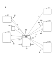
- FIG. 2 is a plan view illustrating an example of an operation performed by the autonomous movement control system of FIG. 1 .
- 11 is a flowchart showing an example of a method for creating travel control information for an automated guided vehicle.
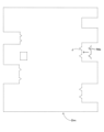
- FIG. 4 is a diagram illustrating an example of a calculation executed in the flowchart of FIG. 3 .
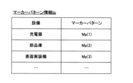
- FIG. 4 is a diagram showing an example of marker pattern information used in the flowchart of FIG. 3 .
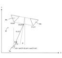
- FIG. 4 is a schematic diagram for explaining a target position registered in the flowchart of FIG. 3 .
- FIG. 4 is a diagram showing an example of target position information used in the flowchart of FIG. 3 .
- FIG. 11 is a flow chart showing an example of a method for correcting a target position and a target direction. 11 is a flowchart showing an example of self-location estimation. 4 is a flowchart showing an example of travel control of the automatic guided vehicle executed by a travel control unit.
- FIG. 11 is a diagram showing an example of the operation executed according to the driving control shown in FIG. 10 .
- FIG. 11 is a diagram showing an example of the operation executed according to the driving control shown in FIG. 10 .
- FIG. 11 is a diagram showing an example of the operation executed according to the driving control shown in FIG. 10 .
- FIG. 11 is a diagram showing an example of the operation executed according to the driving control shown in FIG. 10 .
- FIG. 1 is a block diagram showing an example of an autonomous mobile control system according to the present invention
- FIG. 2 is a plan view showing a schematic diagram of the operation executed by the autonomous mobile control system of FIG. 1.
- FIG. 2 shows the X direction, which is a horizontal direction, and the Y direction, which is a horizontal direction perpendicular to the X direction.
- the X direction and the Y direction correspond to the X axis and the Y axis, respectively, of the world coordinate system.
- the autonomous mobile control system 1 includes an autonomously traveling automated guided vehicle 3, and a control server 5 that controls the automated guided vehicle 3.
- the unmanned guided vehicle 3 comprises a vehicle body 31 and a number of wheels 32 that drive the vehicle body 31, and the unmanned guided vehicle 3 moves as the wheels 32 rotate.
- the specific configuration for driving the vehicle body 31 is not limited to the wheels 32, and may be, for example, a caterpillar track.
- the unmanned guided vehicle 3 also has a travel motor 33 that drives the wheels 32, and a steering wheel 34 that changes the direction of the wheels 32.
- the travel motor 33 drives the wheels 32, causing the wheels 32 to rotate and the unmanned guided vehicle 3 to move.
- the steering wheel 34 changes the direction of the wheels 32, thereby changing the direction in which the unmanned guided vehicle 3 moves.
- the automated guided vehicle 3 is equipped with an environment recognition sensor 35 that detects the surrounding environment 9.
- the environment recognition sensor 35 is a two-dimensional LiDAR (Light Detection and Ranging).
- the environment recognition sensor 35 scans a predetermined scanning range around the automated guided vehicle 3 to detect objects 91-94 located around the automated guided vehicle 3, and acquires point cloud data Dp indicating the shapes of the objects 91-94.
- the automated guided vehicle 3 is equipped with a calculation unit 36.
- This calculation unit 36 is a processor such as a CPU (Central Processing Unit).
- This calculation unit 36 is configured with a self-position estimation unit 361 and a driving control unit 362.
- the self-position estimation unit 361 estimates the position (self-position) of the automated guided vehicle 3 in the world coordinate system based on the point cloud data Dp acquired by the environment recognition sensor 35.
- the driving control unit 362 controls the travel motor 33 and steering wheel 34 based on the self-position estimated by the self-position estimation unit 361, thereby causing the automated guided vehicle 3 to travel along a predetermined route.
- the automated guided vehicle 3 also includes a memory unit 37 and a communication unit 38.
- the communication unit 38 is a storage device such as a solid state drive (SSD).
- SSD solid state drive
- the communication unit 38 performs wireless communication with the control server 5.
- the control server 5 comprises a calculation unit 51, a memory unit 52, a communication unit 53, and a UI (User Interface) 54.
- the calculation unit 51 is, for example, a processor such as a CPU
- the memory unit 52 is, for example, a storage device such as an SSD.
- the memory unit 52 stores an autonomous movement control program 7, and the calculation unit 51 executes the autonomous movement control program 7 to form a movement command unit 511, a map creation unit 512, a marker registration unit 513, and a target position registration unit 514. Details of these functional units 511 to 514 will be described later.
- the communication unit 53 performs wireless communication with the communication unit 38 of the automated guided vehicle 3.
- the UI 54 comprises input devices such as a mouse and a keyboard that accept user operations, and an output device such as a display that outputs information to the user. It is not necessary to configure the input devices and output devices of the UI 54 separately, and they may be configured as an integrated unit using a touch panel display or the like.
- the environment 9 contains various objects such as a charger 91, a parts storeroom 92, a surface mounter 93, and pillars 94.
- a marker M indicating the position of the equipment (the charger 91, the parts storeroom 92, or the surface mounter 93) on which the automated guided vehicle 3 performs a specified task is attached.
- Each marker M has a pair of protrusions Mv arranged at a horizontal interval.
- Each protrusion Mv has a triangular shape in a plan view.
- the environment recognition sensor 35 of the automated guided vehicle 3 scans the environment 9 around the automated guided vehicle 3 with light L (laser light) and detects the light L reflected from the environment 9, thereby acquiring point cloud data Dp indicating the shape of the environment 9.
- control server 5 can use the point cloud data Dp received from the traveling automated guided vehicle 3 to create various information required for driving control of the automated guided vehicle 3. This point will be explained next.
- FIG. 3 is a flowchart showing an example of a method for creating driving control information for an automated guided vehicle
- FIG. 4 is a diagram showing an example of a calculation executed in the flowchart of FIG. 3
- FIG. 5 is a diagram showing an example of marker pattern information used in the flowchart of FIG. 3
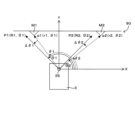
- FIG. 6 is a diagram for explaining the target position registered in the flowchart of FIG. 3
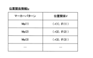
- FIG. 7 is a diagram showing an example of target position information used in the flowchart of FIG. 3.
- the flowchart of FIG. 3 is executed by the calculation unit 51 of the control server 5.
- step S101 the map creation unit 512 acquires point cloud data Dp from the communication unit 38 of the automated guided vehicle 3 via the communication unit 53.
- the automated guided vehicle 3 acquires point cloud data Dp using the environment recognition sensor 35 while traveling in the environment 9 and transmits it to the communication unit 53 of the control server 5, and the map creation unit 512 acquires this point cloud data Dp.
- the map creation unit 512 acquires the point cloud data Dp, which is scan data acquired by the environment recognition sensor 35 scanning the environment 9, and vehicle position data (odometry data) indicating the position of the automated guided vehicle 3 in the world coordinate system.
- step S102 the map creation unit 512 determines whether acquisition of point cloud data Dp has been completed for the entire map creation target range (i.e., whether mapping has been completed). Then, when mapping is completed ("YES" in step S102), the map creation unit 512 creates the environment map data Dm ( Figure 4) that shows a map of the environment 9 in the world coordinate system by combining the point cloud data Dp and the transport vehicle position data (step S103).
- the marker registration unit 513 searches the environmental map data Dm for a target portion J that matches a marker pattern Mp indicating the pattern of the marker M by pattern matching.
- the configuration of the marker M (the shape of the protrusions Mv, the size of the protrusions Mv, or the distance between a pair of protrusions Mv, etc.) varies depending on the type of equipment to which the marker M is attached. This makes it possible to determine the type of equipment to which the marker M is attached based on the marker M. Correspondingly, as shown in FIG.
- the marker registration unit 513 registers the target portion J in the environmental map data Dm in step S106 as a marker M attached to the equipment corresponding to the marker pattern Mp that matches the target portion J. This registers the position and angle of the marker M in the environmental map data Dm.
- the target position registration unit 514 registers the target position Tp and the target direction Td (target angle) in the environmental map data Dm by setting the target position Tp and the target direction Td (target angle) for the marker M registered in step S106.
- This target position Tp indicates the route for the automated guided vehicle 3 to approach the marker M (in other words, the equipment to which the marker M is attached), in other words, the target position Tp is set on the route through which the automated guided vehicle 3 will pass as it approaches the marker M.
- the automated guided vehicle 3 stops once at the target position Tp before approaching the marker M.
- the automated guided vehicle 3 may approach the marker M by passing through the target position Tp without stopping at the target position Tp.
- step S107 the target position registration unit 514 sets the target position Tp to satisfy the positional relationship V in FIG. 6 relative to the marker M.
- the positional relationship V is a vector given by a distance r and an angle ⁇ .
- FIG. 6 the coordinates (x1, y1) and (x2, y2) of the vertices of the two protrusions Mv included in the marker M and the coordinates (x3, y3) of the midpoint of these vertices are shown.
- the target position Tp is set to satisfy the positional relationship V relative to this midpoint (x3, y3).
- the positional relationship V indicates a position relative to the midpoint (x3, y3), and more specifically, indicates the distance r from the midpoint (x3, y3) and the angle ⁇ relative to the midpoint (x3, y3).
- the position coordinates of the target position Tp in the world coordinates are given by (x3-r ⁇ sin( ⁇ + ⁇ ),x3-r ⁇ cos( ⁇ + ⁇ ))
- the target position registration unit 514 sets the target direction Td to the angle ⁇ indicated by the positional relationship V.
- This target direction Td is the direction (angle) in which the automated guided vehicle 3 located at the target position Tp should face.
- the target position registration unit 514 registers the target direction Td and the target position Tp that satisfy the positional relationship V with respect to the marker M in the environmental map data Dm.
- step S107 the target position registration unit 514 registers the target position Tp and the target direction Td so as to satisfy the positional relationship V corresponding to the marker pattern Mp used in the search for the target portion J.
- positional relationship information Iv indicating the correspondence between the marker pattern Mp and the positional relationship V corresponding to the marker pattern Mp is stored in the storage unit 52 (FIG. 7).
- the positional relationship V differs depending on the marker pattern Mp. Therefore, in step S107, the target position registration unit 514 registers the target position Tp and the target direction Td so as to satisfy the positional relationship V associated with the marker pattern Mp used in the search for the target portion J by the positional relationship information Iv.
- step S108 the marker registration unit 513 determines whether steps S104 to S107 have been completed for all marker patterns Mp indicated by the marker pattern information Ip. If steps S104 to S107 have not been completed for all marker patterns Mp (step S108: NO), the marker pattern Mp is changed and steps S104 to S107 are executed.
- the marker registration unit 513 determines whether registration has been completed for all markers M placed in the environment 9. In other words, the marker registration unit 513 has marker installation information indicating all markers M placed in the environment 9, and executes the determination of step S109 based on the marker installation information. If it is determined that registration has not been completed for some markers M (NO in step S109), the marker registration unit 513 notifies the user via the UI 54 to manually register the incompletely registered markers M (step S110). Then, the marker registration unit 513 registers the marker M in the environmental map data Dm in response to the user's operation on the UI 54.
- the marker registration unit 513 registers the target position Tp and the target direction Td for the marker M in the same manner as in step S107. Then, the flowchart of FIG. 3 ends. On the other hand, if it is determined in step S109 that registration has been completed for all markers M (YES), the flowchart in FIG. 3 ends.
- the movement command unit 511 controls the automated guided vehicle 3 based on this information, thereby causing the automated guided vehicle 3 to travel in the environment 9.
- a target portion J corresponding to a marker M provided in the environment 9 is extracted from the environmental map data Dm (steps S104 to S105), and the target portion J is registered as a marker M (step S106). In this way, it is possible to simply and accurately register the marker M used to estimate the self-position of the automated guided vehicle 3 (autonomous mobile body).
- the identification of the marker M is performed by the control server 5, not by the automated guided vehicle 3 (steps S103 to S106). Therefore, the automated guided vehicle 3 does not need to identify the marker M, and only needs to transmit the point cloud data Dp acquired by the environment recognition sensor 35 while traveling through the environment 9 to the control server 5. As a result, there is no need to stop the automated guided vehicle 3 to identify the marker M, and the necessary point cloud data Dp can be quickly acquired.
- the marker M is provided for the equipment (charger 91, parts warehouse 92, and surface mounter 93) installed in the environment 9.
- the target position registration unit 514 registers the target position Tp indicating the route for the automated guided vehicle 3 to approach the equipment installed in the environment 9 so as to satisfy a predetermined positional relationship V with the marker M extracted by the marker registration unit 513 (step S107).
- the target position Tp indicating the route for the automated guided vehicle 3 to approach the equipment installed in the environment 9 can be registered simply and accurately.
- a UI 54 is provided to accept user operations, and the marker registration unit 513 registers the target position Tp in response to the operation accepted by the UI 54 (step S110).
- the user can register the target position Tp in the control server 5 (autonomous mobile control device) as necessary.
- the automated guided vehicle 3 detects the environment 9 around the automated guided vehicle 3 while traveling through the environment 9, and the map creation unit 512 (map data acquisition unit) acquires the environmental map data Dm by creating it based on the environment 9 (in other words, the point cloud data Dp) detected by the automated guided vehicle 3 (steps S101 to S103).
- the automated guided vehicle 3 detects the markers M and equipment in the environment using the same environmental recognition sensor 35 (sensor). In this configuration, the position of the markers M and the equipment can both be detected by the same environmental recognition sensor 35, making it possible to reduce the number of sensors to be mounted on the automated guided vehicle 3.
- the marker M has a configuration according to the type of equipment to which the marker M is attached.
- the target position registration unit 514 registers the target position Tp so as to satisfy a positional relationship V that differs according to the configuration of the marker M extracted by the marker registration unit 513 (step S107). With this configuration, the target position Tp can be appropriately registered according to the type of equipment.
- positional relationship information Iv (FIG. 7) indicating the positional relationship V between the marker M and the target position Tp is stored in the storage unit 52. Then, the target position registration unit 514 registers the target position Tp with respect to the marker M so as to satisfy the positional relationship V indicated by the positional relationship information Iv (step S107). With this configuration, the target position Tp can be accurately registered with respect to the marker M based on the positional relationship information Iv.
- the target position registration unit 514 also registers the target direction Td, which is the direction of the automated guided vehicle 3 at the target position Tp, with the marker M together with the target position Tp (step S107). With this configuration, the automated guided vehicle 3 can approach the equipment in an appropriate direction (target direction Td) from the target position Tp.
- the marker registration unit 513 also compares the marker pattern Mp (marker information) indicating the configuration of the marker M with the environmental map data Dm to extract the target portion J corresponding to the marker M provided in the environment 9 from the environmental map data Dm (steps S104 to S105). With this configuration, the marker M can be registered simply and accurately based on the environmental map data Dm.
- the marker registration unit 513 also compares the marker pattern Mp with the environmental map data Dm by pattern matching (steps S104 to S105). With this configuration, the marker M can be registered simply and accurately based on the environmental map data Dm.
- step S201 the movement command unit 511 of the control server 5 sets the destination of the automated guided vehicle 3.
- step S202 the movement command unit 511 calculates the driving route of the automated guided vehicle 3 to the destination based on the environmental map data Dm (step S202).
- the environmental map data Dm is a grid map made up of multiple lattices, and each lattice has a value greater than 0 and less than 1. Pillars 94 that are obstacles to the driving of the automated guided vehicle 3 and lattices in the vicinity of the pillars 94 have large values, while lattices in an area suitable for the driving of the automated guided vehicle 3 have small values.
- the movement command unit 511 calculates the driving route so that the sum of the values of each lattice in the driving route of the automated guided vehicle 3 to the destination is minimized.
- the communication unit 38 of the automated guided vehicle 3 receives a driving command from the communication unit 53 of the control server 5 to instruct the automated guided vehicle 3 to drive along the driving route calculated in step S202 (step S203).
- the driving control unit 362 of the automated guided vehicle 3 then controls the driving motor 33 and steering wheel 34 based on the driving command, thereby driving the automated guided vehicle 3 along the driving route indicated by the driving command (step S204).
- the self-position estimation unit 361 also estimates the position (self-position) of the automated guided vehicle 3 based on the detection results of the environment recognition sensor 35 and the environmental map data Dm, and determines whether the target position Tp has been reached (step S205).
- the self-position estimation unit 361 calculates the relative position of the marker M with respect to the automated guided vehicle 3 (i.e., the position of the marker M in the local coordinates) (step S208). The self-position estimation unit 361 then calculates the amount of deviation between the relative position of the marker M and the positional relationship V with respect to the marker M, and compares this amount of deviation with a threshold (step S209). Specifically, the deviation amounts ⁇ r and ⁇ of the distance r and angle ⁇ are calculated, and the deviation amount ⁇ r of the distance r is compared with the distance threshold, and the deviation amount ⁇ of the angle ⁇ is compared with the angle threshold. If both are less than the corresponding thresholds, the determination in step S209 is "NO," and the flowchart in FIG. 8 ends.
- step S209 returns "YES” and steps S210 and S211 are executed.
- step S210 the driving control unit 362 moves the automated guided vehicle 3 to a position where the deviation ⁇ r of the distance r and the deviation ⁇ of the angle ⁇ are each less than a predetermined value (step S210).
- the target position registration unit 514 of the control server 5 corrects the target position Tp and target direction Td by registering the position and direction of the automated guided vehicle 3 moved in step S210 as the target position Tp and target direction Td (step S211). Then, the flowchart in FIG. 8 ends.
- the automated guided vehicle 3 when the automated guided vehicle 3 reaches the target position Tp registered by the target position registration unit 514 ("YES" in step S205), it detects the position of the marker M relative to the automated guided vehicle 3 ("YES" in step S206). Then, the target position registration unit 514 corrects the target position Tp based on the position of the marker M detected by the automated guided vehicle 3. In this configuration, the target position Tp can be accurately corrected based on the position of the marker M detected by the automated guided vehicle 3 that has actually moved to the registered target position Tp.
- the automated guided vehicle 3 estimates its own position (self-position) while traveling in the environment 9. At this time, the estimated self-position may be corrected based on the detection result of the marker M ( Figure 9).
- FIG. 9 is a flowchart showing an example of self-position estimation.
- the self-position estimation in FIG. 9 functions well in an environment 9 in which the automated guided vehicle 3 travels between flat walls extending on both sides, and is executed in parallel while the automated guided vehicle 3 is traveling.
- the self-position estimation unit 361 detects the environment 9 using the environment recognition sensor 35 (step S301), and estimates the position (self-position) of the automated guided vehicle 3 by comparing the detection result by the environment recognition sensor 35 with the environmental map data Dm (step S302).
- the self-position estimation unit 361 determines whether the environment recognition sensor 35 has detected the marker M based on the detection result in step S301. If the detection of the marker M cannot be confirmed (if "NO" in step S303), the process returns to step S301.
- the self-position estimation unit 361 detects the marker M, it compares the coordinates (xr, yr) of the marker M registered in the environmental map data Dm with the coordinates (xd, yd) of the marker M calculated from the detection result of the environment recognition sensor 35.
- the environmental map data Dm and the coordinates of the marker M are stored in advance in the storage unit 37. Then, if the magnitude of these deviation amounts (xr-xd, yr-yd) is less than the threshold value (if "NO" in step S304), the process returns to step S301.
- the self-position estimation unit 361 corrects the self-position estimated in step S302 by the deviation amount (step S305) and returns to step S301.
- the automated guided vehicle 3 is equipped with an environment recognition sensor 35 that detects the environment 9, a self-position estimation unit 361 that estimates the position of the automated guided vehicle 3 by referring to the result of the detection of the environment 9 by the environment recognition sensor 35 and the environmental map data Dm, and a memory unit 37 (marker coordinate memory unit) that stores the position coordinates of the registered marker M. Then, when the environment recognition sensor 35 detects the marker M, the self-position estimation unit 361 corrects the estimated position by referring to the environmental map data Dm based on the position of the marker M detected by the environment recognition sensor 35 (detected position) and the position coordinates of the marker M stored in the memory unit 37. Therefore, the automated guided vehicle 3 can accurately correct the position of the automated guided vehicle 3 (self-position) based on the position of the marker M detected by the environment recognition sensor 35 and the position coordinates of the marker M.
- the autonomous movement control system 1 corresponds to an example of an "autonomous movement control system” of the present invention
- the automated guided vehicle 3 corresponds to an example of an "autonomous moving body” of the present invention
- the environment recognition sensor 35 corresponds to an example of a "sensor” of the present invention
- the self-position estimation unit 361 corresponds to an example of a "self-position estimation unit” of the present invention
- the memory unit 37 corresponds to an example of a "marker coordinate memory unit” of the present invention
- the control server 5 corresponds to an example of an "autonomous movement control device" of the present invention
- the map creation unit 512 corresponds to an example of a "map data acquisition unit” of the present invention
- the marker registration unit 513 corresponds to an example of a "marker registration unit” of the present invention
- the target position registration unit 514 corresponds to an example of a "target position registration unit” of the present invention
- the memory unit 52 corresponds to an example of a "memory the UI 54 corresponds
- step S110 of FIG. 3 the method of registering the target position Tp and the target direction Td can be modified.
- the user inputs the position coordinates of the marker M by operating the UI 54.
- the movement command unit 511 moves the automated guided vehicle 3 toward the position coordinates, and causes the environment recognition sensor 35 to detect the marker M at the position coordinates.
- the marker registration unit 513 registers the marker M in the environment map data Dm based on the detection result of the marker M by the environment recognition sensor 35.
- the marker M and the environment recognition sensor 35 that detects the marker M are conceivable.
- the marker M may be a barcode or a QR code (registered trademark)
- the environment recognition sensor 35 may be a three-dimensional LiDAR, a color image sensor, a depth-sensing camera, or a stereo camera.
- the autonomous movement control program 7 can also be acquired by downloading it to the control server 5 from an external server (cloud server) that is provided separately from the control server 5.
- the external server functions as an example of the "recording medium" of the present invention.
- the environment recognition sensor 35 acquires point cloud data Dp indicating the three-dimensional shape of surrounding objects by scanning in a rotational direction around a central axis parallel to the vertical direction, and this point cloud data Dp is represented by polar coordinates consisting of a combination of distance and rotational position.
- this point cloud data Dp is represented by polar coordinates consisting of a combination of distance and rotational position.
- the detection positions p1 and p2 of markers M1 and M2 detected by the environment recognition sensor 35 are shown by polar coordinates (r1, ⁇ 1) and (r2, ⁇ 2).
- the distances r1 and r2 are the distances from the environment recognition sensor 35 to the detection positions p1 and p2 of markers M1 and M2, and the angles ⁇ 1 and ⁇ 2 are the angles of the detection positions p1 and p2 of markers M1 and M2 relative to the environment recognition sensor 35.
- the reference positions P1 and P2 of the markers M1 and M2 are shown by polar coordinates (R1, ⁇ 1) and (R2, ⁇ 2).
- the reference positions P1 and P2 are the detected positions p1 and p2 of the markers M1 and M2 that the self-position estimation unit 361 should acquire when the automated guided vehicle 3 moves to the destination 90, and are included in the reference position data Dr.
- the detected positions p1 and p2 of the markers M1 and M2 coincide with the reference positions P1 and P2 of the markers M1 and M2, respectively.
- the self-position estimation unit 361 and the driving control unit 362 appropriately read out the reference position data Dr from the memory unit 37 and execute the control described below.
- FIGS. 11A to 11C show the state of the environment recognition sensor 35 before it reaches the destination 90
- FIG. 11D shows the state of the environment recognition sensor 35 when it reaches the destination 90.
- step S401 the self-position estimation unit 361 causes the environment recognition sensor 35 to perform a scan and acquires point cloud data Dp from the environment recognition sensor 35. Then, the self-position estimation unit 361 acquires the detected positions p1 and p2 of the markers M1 and M2 based on the point cloud data Dp.
- step S402 the traveling control unit 362 determines whether the amount of deviation of the detection positions p1 and p2 of the markers M1 and M2 from the reference positions P1 and P2 of the markers M1 and M2 in the rotation direction of the polar coordinates is within an allowable range.
- ⁇ y
- step S404 if the distance ⁇ y shown in FIG. 11A is less than the threshold ⁇ Yth, it is determined that the deviation in the rotational direction is within the allowable range ("YES" in step S402), and the process proceeds to step S404.
- the distance ⁇ y shown in FIG. 11A is equal to or greater than the threshold ⁇ Yth, it is determined that the deviation in the rotational direction is outside the allowable range ("NO" in step S402), and the process proceeds to step S404 after executing step S403.
- the method of evaluating the deviation in the rotational direction is not limited to this example, and the deviation in the rotational direction may also be evaluated based on whether the angle between a straight line passing through the reference positions P1, P2 of the markers M1, M2 and a straight line passing through the detection positions p1, p2 of the markers M1, M2 is less than a predetermined threshold angle.
- step S402 is executed in the state shown in FIG. 11A, and the result is determined to be "NO.” Therefore, in step S403, the travel control unit 362 controls the steering 34 according to the distance ⁇ y, thereby rotating the automated guided vehicle 3 in the rotation direction so that the distance ⁇ y decreases to less than the threshold value ⁇ Yth.
- FIG. 11B The result of executing step S403 from the state shown in FIG. 11A is shown in FIG. 11B. As shown in FIG. 11B, the distance ⁇ y is substantially zero.
- step S404 the traveling control unit 362 determines whether the amount of deviation of the detection positions p1, p2 of the markers M1, M2 from the reference positions P1, P2 of the markers M1, M2 in the Y direction (the direction corresponding to the Y coordinate) is within a permissible range.
- ⁇ y1
- ⁇ y2
- the determination is made based on: Y1th: a predetermined threshold value corresponding to an acceptable range Y2th: a predetermined threshold value corresponding to an acceptable range, and the threshold value Y1th and the threshold value Y2th are equal.
- the distance ⁇ y1 and the distance ⁇ y2 are equal. Therefore, if the distance ⁇ y1 shown in FIG. 11B is less than the threshold value Y1th, it is determined that the deviation in the Y direction is within the allowable range ("YES" in step S404), and the process proceeds to step S406. On the other hand, if the distance ⁇ y1 shown in FIG. 11B is equal to or greater than the threshold value Y1th, it is determined that the deviation in the Y direction is outside the allowable range ("NO" in step S404), and the process executes step S405 before proceeding to step S406.
- step S404 is executed in the state shown in FIG. 11B, and the result is determined to be "NO.” Therefore, in step S405, the travel control unit 362 controls the travel motor 13 according to the distance ⁇ y1, thereby moving the automated guided vehicle 3 in the Y direction so that the distance ⁇ y1 decreases to less than the threshold value Y1th.
- the result of executing step S405 from the state shown in FIG. 11B is shown in FIG. 11C. As shown in FIG. 11C, the distance ⁇ y1 is essentially zero.
- step S406 the traveling control unit 362 determines whether the amount of deviation of the detection positions p1, p2 of the markers M1, M2 from the reference positions P1, P2 of the markers M1, M2 in the X direction (the direction corresponding to the X coordinate) is within an allowable range. Note that in this example, the deviation in the rotation direction in the polar coordinates is evaluated instead of the X direction, so that the deviation in the X coordinate is essentially evaluated.
- ⁇ 1
- ⁇ 1th ⁇ 2
- ⁇ 1th a predetermined threshold value corresponding to an allowable range
- ⁇ 2th a predetermined threshold value corresponding to an allowable range
- step S406 if the angle ⁇ 1 shown in FIG. 11C is less than the threshold ⁇ 1th and the angle ⁇ 2 shown in FIG. 11C is less than the threshold ⁇ 2th, it is determined that the deviation in the X direction is within the allowable range ("YES" in step S406) and the flowchart in FIG. 10 is terminated.
- the angle ⁇ 1 shown in FIG. 11C is equal to or greater than the threshold ⁇ 1th or the angle ⁇ 2 shown in FIG. 11C is equal to or greater than the threshold ⁇ 2th, it is determined that the deviation in the X direction is outside the allowable range ("NO" in step S406), and step S407 is executed before the flowchart in FIG. 10 is terminated.
- step S406 is executed in the state shown in FIG. 11C, and the result is determined to be "NO.” Therefore, in step S407, the travel control unit 362 controls the travel motor 13 and steering wheel 34 according to the angles ⁇ 1 and ⁇ 2, thereby moving the automated guided vehicle 3 to the X coordinate so that the angles ⁇ 1 and ⁇ 2 are reduced to less than the thresholds ⁇ 1th and ⁇ 2th, respectively.
- the result of executing step S407 from the state shown in FIG. 11C is shown in FIG. 11D. As shown in FIG. 11D, the angles ⁇ 1 and ⁇ 2 are each essentially zero.
Landscapes
- Engineering & Computer Science (AREA)
- Physics & Mathematics (AREA)
- General Physics & Mathematics (AREA)
- Radar, Positioning & Navigation (AREA)
- Remote Sensing (AREA)
- Theoretical Computer Science (AREA)
- Mathematical Physics (AREA)
- Business, Economics & Management (AREA)
- Educational Administration (AREA)
- Educational Technology (AREA)
- Automation & Control Theory (AREA)
- Control Of Position, Course, Altitude, Or Attitude Of Moving Bodies (AREA)
Abstract
環境地図データDmのうちから、環境9に設けられたマーカーMに相当する対象部分Jが抽出されて(ステップS104~S105)、当該対象部分JがマーカーMとして登録される(ステップS106)。こうして、無人搬送車3(自律移動体)の自己位置の推定に使用されるマーカーMを簡便かつ的確に登録することが可能となっている。
Description
この発明は、自律的に走行する自律移動体の走行を制御する技術に関する。
特許文献1には、自律的に走行する無人搬送車(自律移動体)の現在位置を推定する技術が記載されている。特に特許文献1では、特定の形状または模様を有する物体の画像がランドマーク画像として環境地図上の座標情報と紐づけて登録される。そして、画像センサーからの画像情報にランドマーク画像が含まれる場合、ランドマーク画像の座標情報に基づき現在位置が推定される。
上記のランドマーク等のマーカーは、自律移動体が自己位置を推定するのに有用である。ただし、自律移動体を制御する自律移動制御装置に対して、マーカーを登録するための作業がユーザーにとって手間であったり、ユーザーが誤ってマーカーを登録したりといった問題があった。
この発明は上記課題に鑑みなされたものであり、自律移動体の自己位置の推定に使用されるマーカーを簡便かつ的確に登録可能とすることを目的とする。
本発明に係る自律移動制御装置は、自律移動体が走行する環境の地図を示す環境地図データを取得する地図データ取得部と、地図データ取得部が取得した環境地図データのうちから、環境に設けられたマーカーに相当する部分を抽出して、当該部分をマーカーとして登録するマーカー登録部とを備える。
本発明に係る自律移動制御システムは、上記の自律移動制御装置と、自律移動制御装置の制御に基づき走行する自律移動体とを備える。
本発明に係る自律移動制御方法は、自律移動体が走行する環境の地図を示す環境地図データを取得する工程と、環境に設けられたマーカーに相当する部分を環境地図データのうちから抽出して当該部分をマーカーとして登録する工程とを備える。
本発明に係る自律移動制御プログラムは、上記の自律移動制御方法の各工程をコンピューターに実行させる。
本発明に係る記録媒体は、自律移動制御プログラムをコンピューターにより読み出し可能に記録する。
このように構成された本発明(自律移動制御装置、自律移動制御システム、自律移動制御プログラムおよび記録媒体)では、環境地図データのうちから、環境に設けられたマーカーに相当する部分が抽出されて、当該部分がマーカーとして登録される。こうして、自律移動体の自己位置の推定に使用されるマーカーを簡便かつ的確に登録することが可能となっている。
また、マーカーは、環境に設置された設備に対して設けられ、自律移動体が環境に設置された設備に接近するための経路を示す目標位置を、マーカー登録部によって抽出されたマーカーに対して所定の位置関係を満たすように登録する目標位置登録部をさらに備えるように、自律移動制御装置を構成してもよい。かかる構成では、自律移動体が環境に設置された設備に接近するための経路を示す目標位置を簡便かつ的確に登録することができる。
また、ユーザーの操作を受け付けるユーザーインターフェースをさらに備え、目標位置登録部は、ユーザーインターフェースが受け付けた操作に応じて、目標位置を登録するように、自律移動制御装置を構成してもよい。かかる構成では、ユーザーは、必要に応じて、自律移動制御装置に対して目標位置を登録することができる。
また、自律移動体は、目標位置登録部によって登録された目標位置に到達すると、当該自律移動体に対するマーカーの位置を検出し、目標位置登録部は、自律移動体が検出したマーカーの位置に基づき目標位置を補正するように、自律移動制御装置を構成してもよい。かかる構成では、登録した目標位置に実際に移動した自律移動体が検出したマーカーの位置に基づき、目標位置を的確に補正できる。
また、自律移動体は、環境を走行しつつ当該自律移動体の周囲の環境を検出し、地図データ取得部は、自律移動体が検出した環境に基づき環境地図データを作成することで環境地図データを取得し、自律移動体は、環境におけるマーカーおよび設備を同一のセンサーによって検出するように、自律移動制御装置を構成してもよい。かかる構成では、マーカーの位置および設備のそれぞれを同一のセンサーで検出でき、センサーの個数を抑えることができる。
また、マーカーは、当該マーカーが付された設備の種類に応じた構成を有し、目標位置登録部は、マーカー登録部によって抽出されたマーカーの構成に応じて異なる位置関係を満たすように、目標位置を登録するように、自律移動制御装置を構成してもよい。かかる構成では、設備の種類に応じて目標位置を適切に登録することができる。
また、マーカーと目標位置との間の位置関係を示す位置関係情報を記憶する記憶部をさらに備え、目標位置登録部は、位置関係情報が示す位置関係を満たすように、目標位置をマーカーに対して登録するように、自律移動制御装置を構成してもよい。かかる構成では、位置関係情報に基づきマーカーに対して目標位置を的確に登録することができる。
また、目標位置登録部は、目標位置における自律移動体の方向である目標方向を目標位置とともにマーカーに対して登録するように、自律移動制御装置を構成してもよい。かかる構成では、自律移動体は、目標位置から適切な方向で設備に接近することができる。
また、マーカー登録部は、マーカーが有する構成を示すマーカー情報と、環境地図データとを照合することで、環境に設けられたマーカーに相当する部分を環境地図データのうちから抽出するように、自律移動制御装置を構成してもよい。かかる構成では、環境地図データに基づきマーカーを簡便かつ的確に登録することができる。
また、マーカー情報は、マーカーが有するパターンを示し、マーカー登録部は、マーカー情報が示すパターンと環境地図データとをパターンマッチングによって照合するように自律移動制御装置を構成してもよい。かかる構成では、環境地図データに基づきマーカーを簡便かつ的確に登録することができる。
本発明に係る自律移動体は、上記の自律移動制御装置の制御に基づき走行する自律移動体であって、環境を検出するセンサーと、センサーが環境を検出した結果と環境地図データとを参照して当該自律移動体の位置を推定する自己位置推定部と、マーカーの位置座標を記憶するマーカー座標記憶部とを備え、センサーがマーカーを検出すると、自己位置推定部は、センサーが検出したマーカーの位置とマーカーの位置座標とに基づき、環境地図データを参照して推定した位置を補正する。このように構成された本発明(自律移動体)では、自律移動体は、センサーが検出したマーカーの位置とマーカーの位置座標とに基づき、当該自律移動体の位置(自己位置)を的確に補正することができる。
本発明によれば、自律移動体の自己位置の推定に使用されるマーカーを簡便かつ的確に登録することが可能となる。
図1は本発明に係る自律移動制御システムの一例を示すブロック図であり、図2は図1の自律移動制御システムで実行される動作を模式的に示す平面図である。図2では、水平方向であるX方向、X方向に直交する水平方向であるY方向が示されている。なお、本明細書では、特に断らない限りは、X方向およびY方向はワールド座標系のX軸およびY軸にそれぞれ対応するものとする。図1に示すように、自律移動制御システム1は、自律的に走行する無人搬送車3と、無人搬送車3を制御する制御サーバー5とを備える。
無人搬送車3は、車両本体31と、車両本体31を駆動する複数の車輪32とを備え、車輪32が回転することで、無人搬送車3が走行する。なお、車両本体31を駆動する具体的構成は車輪32に限られず、例えば無限軌道でも構わない。また、無人搬送車3は、車輪32を駆動する走行モータ33と、車輪32の方向を変更するステアリング34とを有する。つまり、走行モータ33が車輪32を駆動することで、車輪32が回転して、無人搬送車3が走行する。また、ステアリング34が車輪32の方向を変更することで、無人搬送車3が走行する方向が変更される。
さらに、無人搬送車3は、周囲の環境9を検出する環境認識センサー35を備える。ここの例では、環境認識センサー35は二次元のLiDAR(Light Detection and Ranging)である。環境認識センサー35は、無人搬送車3の周囲の所定の走査範囲を走査することで、当該無人搬送車3の周囲に位置する物体91~94を検出して、当該物体91~94の形状を示す点群データDpを取得する。
さらに、無人搬送車3は、演算部36を備える。この演算部36は例えばCPU(Central Processing Unit)等のプロセッサーである。この演算部36には、自己位置推定部361および走行制御部362が構成される。自己位置推定部361は、環境認識センサー35によって取得された点群データDpに基づき、ワールド座標系における無人搬送車3の位置(自己位置)を推定する。走行制御部362は、自己位置推定部361によって推定した自己位置に基づき走行モータ33およびステアリング34を制御することで、無人搬送車3を所定のルートに沿って走行させる。
また、無人搬送車3は、記憶部37および通信部38を備える。通信部38は、SSD(Solid State Drive)等の記憶装置である。通信部38は、制御サーバー5と無線通信を実行する。
制御サーバー5は、演算部51、記憶部52、通信部53およびUI(User Interface)54を備える。演算部51は例えばCPU等のプロセッサーであり、記憶部52は例えばSSD等の記憶装置である。記憶部52は自律移動制御プログラム7が保存され、演算部51は自律移動制御プログラム7を実行することで、移動指令部511、地図作成部512、マーカー登録部513および目標位置登録部514を構成する。これらの機能部511~514の詳細は後述する。通信部53は、無人搬送車3の通信部38と無線通信を実行する。UI54は、ユーザーの操作を受け付けるマウスやキーボード等の入力機器と、ユーザーに情報を出力するディスプレイ等の出力機器とを備える。なお、UI54の入力機器と出力機器とを別体で構成する必要はなく、タッチパネルディスプレイ等によってこれらを一体的に構成してもよい。
図2に示すように、環境9には、充電器91、部品庫92、表面実装機93あるいは柱94といった各種の物体が存在する。これらのうち、無人搬送車3が所定の作業を行う対象となる設備(充電器91、部品庫92あるいは表面実装機93)に対しては、当該設備の位置を示すマーカーMが取り付けられている。各マーカーMは、水平方向に間隔を空けて配列された一対の突起Mvを有する。各突起Mvは平面視において三角形を有する。 そして、無人搬送車3の環境認識センサー35は当該無人搬送車3の周囲の環境9に対して光L(レーザー光)を走査して、環境9から反射された光Lを検知することで、環境9の形状を示す点群データDpを取得する。
ところで、本実施例では、制御サーバー5は、走行中の無人搬送車3から受信した点群データDpを用いて、無人搬送車3の走行制御に必要となる各種情報を作成することができる。この点について、次に説明する。
図3は無人搬送車の走行制御情報の作成方法の一例を示すフローチャートであり、図4は図3のフローチャートで実行される演算の一例を模式的に示す図であり、図5は図3のフローチャートで使用されるマーカーパターン情報の一例を模式的に示す図であり、図6は図3のフローチャートで登録される目標位置を説明するための模式図であり、図7は図3のフローチャートで使用される目標位置情報の一例を模式的に示す図である。図3のフローチャートは、制御サーバー5の演算部51によって実行される。
ステップS101では、地図作成部512は、無人搬送車3の通信部38から通信部53を介して点群データDpを取得する。具体的には、無人搬送車3は、環境9を走行しつつ環境認識センサー35によって点群データDpを取得して、制御サーバー5の通信部53に送信し、地図作成部512はこの点群データDpを取得する。この際、地図作成部512は、環境認識センサー35が環境9を走査することで取得した走査データである点群データDpと、ワールド座標系における無人搬送車3の位置を示す搬送車位置データ(オドメトリデータ)とを取得する。ステップS102では、地図作成部512は、地図作成対象範囲の全体について点群データDpの取得を完了したか(すなわち、マッピングを完了したか)を判定する。そして、マッピングが完了すると(ステップS102で「YES」)、地図作成部512は、点群データDpと搬送車位置データとを合成することで、ワールド座標系において環境9の地図を示す環境地図データDm(図4)を作成する(ステップS103)。
ステップS104では、マーカー登録部513は、マーカーMのパターンを示すマーカーパターンMpと一致する対象部分Jをパターンマッチングによって環境地図データDmのうちから探索する。なお、マーカーMの構成(突起Mvの形状、突起Mvの大きさあるいは一対の突起Mvの間隔等)は、当該マーカーMが付された設備の種類に応じて異なる。これによって、マーカーMに基づき当該マーカーMが付された設備の種類が判別可能となる。これに対応して、図5に示すように、設備の種類と、当該種類に応じたマーカーMのパターンを有するマーカーパターンMp(N)(N=1、2、3、…)とを対応付けたマーカーパターン情報Ipが記憶部52に保存されている。そして、ステップS104では、マーカーパターン情報Ipに含まれる複数のマーカーパターンMpのうちの一のマーカーパターンMpを用いてパターンマッチングが実行される。
環境地図データDmのうちに対象部分Jが存在する場合(ステップS105で「YES」の場合)、マーカー登録部513は、ステップS106において、対象部分Jを、当該対象部分Jに一致するマーカーパターンMpに対応する設備に付されたマーカーMとして、環境地図データDmに対して登録する。これによって、環境地図データDmにおいて、マーカーMの位置や角度が登録される。
ステップS107では、目標位置登録部514は、ステップS106で登録されたマーカーMに対して目標位置Tpと目標方向Td(目標角度)を設定することで、環境地図データDmに対して目標位置Tpと目標方向Tdを登録する。この目標位置Tpは、無人搬送車3がマーカーM(換言すれば、当該マーカーMが付された設備)に接近するための経路を示し、換言すれば、目標位置TpはマーカーMに接近する無人搬送車3が通過する経路上に設定される。ここの例では、無人搬送車3は、マーカーMに接近する前に、目標位置Tpで一旦停止する。ただし、無人搬送車3は、目標位置Tpで停止せずに目標位置Tpを通過してマーカーMに接近しても構わない。
ステップS107では、かかる目標位置TpがマーカーMに対して図6の位置関係Vを満たすように目標位置登録部514によって設定される。位置関係Vは、距離rと角度θとで与えられるベクトルである。図6では、マーカーMに含まれる2個の突起Mvそれぞれの頂点の座標(x1,y1)(x2,y2)と、これら頂点の中点の座標(x3,y3)とが示されている。そして、目標位置Tpは、この中点(x3,y3)に対して位置関係Vを満たすように設定される。つまり、位置関係Vは、中点(x3,y3)に対する位置を示し、詳細には、中点(x3,y3)からの距離rと中点(x3,y3)に対する角度θとを示す。2個の突起Mvの頂点(x1,y1)(x2,y2)を通る直線の法線とY軸との角度φを用いると、ワールド座標における目標位置Tpの位置座標は、
(x3-r・sin(θ+φ),x3-r・cos(θ+φ))
となる。さらに、目標位置登録部514は、目標方向Tdを位置関係Vが示す角度θに設定する。この目標方向Tdは、目標位置Tpに位置する無人搬送車3が向くべき方向(角度)である。こうして、目標位置登録部514は、マーカーMに対して位置関係Vを満たす目標方向Tdおよび目標位置Tpを環境地図データDmに対して登録する。
(x3-r・sin(θ+φ),x3-r・cos(θ+φ))
となる。さらに、目標位置登録部514は、目標方向Tdを位置関係Vが示す角度θに設定する。この目標方向Tdは、目標位置Tpに位置する無人搬送車3が向くべき方向(角度)である。こうして、目標位置登録部514は、マーカーMに対して位置関係Vを満たす目標方向Tdおよび目標位置Tpを環境地図データDmに対して登録する。
なお、目標位置Tpおよび目標方向TdがマーカーMに対して満たすべき位置関係Vは、設備の種類に応じて、換言すれば当該設備に付されたマーカーMの構成に応じて異なる。そこで、ステップS107では、目標位置登録部514は、対象部分Jの探索に用いたマーカーパターンMpに応じた位置関係Vを満たすように、目標位置Tpおよび目標方向Tdを登録する。具体的には、マーカーパターンMpと、当該マーカーパターンMpに対応する位置関係Vとを対応付けて示す位置関係情報Ivが記憶部52に保存されている(図7)。位置関係情報Ivが示すように、マーカーパターンMpに応じて位置関係Vは異なる。そこで、ステップS107では、目標位置登録部514は、対象部分Jの探索に用いたマーカーパターンMpに位置関係情報Ivによって対応付けられた位置関係Vを満たすように、目標位置Tpおよび目標方向Tdを登録する。
ステップS108では、マーカー登録部513は、マーカーパターン情報Ipが示す全てのマーカーパターンMpについてステップS104~S107を完了したかを判定する。全マーカーパターンMpについてステップS104~S107が完了していない場合(ステップS108で「NO」の場合)には、マーカーパターンMpを変更してステップS104~S107を実行する。
全マーカーパターンMpについてステップS104~S107が完了している場合(ステップS108で「YES」の場合)には、マーカー登録部513は、環境9に設けられた全てのマーカーMについて登録が完了したかを判定する。つまり、マーカー登録部513は、環境9に設置された全てのマーカーMを示すマーカー設置情報を有しており、当該マーカー設置情報に基づき、ステップS109の判定を実行する。一部のマーカーMについて登録が完了していないと判定すると(ステップS109で「NO」)、マーカー登録部513は、登録未完の当該一部のマーカーMを手動で登録するように、UI54によってユーザーに報知する(ステップS110)。そして、マーカー登録部513は、UI54に対するユーザーの操作に応じて、マーカーMを環境地図データDmに対して登録する。さらに、マーカー登録部513は、ステップS107と同様にして、当該マーカーMに対して目標位置Tpおよび目標方向Tdを登録する。そして、図3のフローチャートが終了する。一方、ステップS109で、全てのマーカーMについて登録が完了したと判定されると(YES)、図3のフローチャートが終了する。
こうして、環境地図データDmの作成や、環境地図データDmに対するマーカーM、目標位置Tpおよび目標方向Tdの登録が完了すると、移動指令部511は、これらの情報に基づき無人搬送車3を制御することで、環境9において無人搬送車3を走行させる。
以上に説明する実施形態では、環境地図データDmのうちから、環境9に設けられたマーカーMに相当する対象部分Jが抽出されて(ステップS104~S105)、当該対象部分JがマーカーMとして登録される(ステップS106)。こうして、無人搬送車3(自律移動体)の自己位置の推定に使用されるマーカーMを簡便かつ的確に登録することが可能となっている。
特に、この実施形態では、マーカーMの特定は、無人搬送車3ではなく制御サーバー5で実行される(ステップS103~S106)。そのため、無人搬送車3は、マーカーMの特定を実行する必要が無く、環境9を走行しつつ環境認識センサー35によって取得した点群データDpを制御サーバー5に送信するだけでよい。その結果、マーカーMの特定のために無人搬送車3を停止させる必要が無く、必要な点群データDpを迅速に取得することができる。
ここで、マーカーMは、環境9に設置された設備(充電器91、部品庫92および表面実装機93)に対して設けられる。これに対して、目標位置登録部514は、無人搬送車3が環境9に設置された設備に接近するための経路を示す目標位置Tpを、マーカー登録部513により抽出されたマーカーMに対して所定の位置関係Vを満たすように登録する(ステップS107)。かかる構成では、無人搬送車3が環境9に設置された設備に接近するための経路を示す目標位置Tpを簡便かつ的確に登録することができる。
また、ユーザーの操作を受け付けるUI54が設けられており、マーカー登録部513は、UI54が受け付けた操作に応じて、目標位置Tpを登録する(ステップS110)。かかる構成では、ユーザーは、必要に応じて、制御サーバー5(自律移動制御装置)に対して目標位置Tpを登録することができる。
また、無人搬送車3は、環境9を走行しつつ当該無人搬送車3の周囲の環境9を検出し、地図作成部512(地図データ取得部)は、無人搬送車3が検出した環境9(換言すれば、点群データDp)に基づき環境地図データDmを作成することで環境地図データDmを取得する(ステップS101~S103)。この際、無人搬送車3は、環境におけるマーカーMおよび設備を同一の環境認識センサー35(センサー)によって検出する。かかる構成では、マーカーMの位置および設備のそれぞれを同一の環境認識センサー35で検出でき、無人搬送車3に搭載するセンサーの個数を抑えることができる。
また、マーカーMは、当該マーカーMが付された設備の種類に応じた構成を有する。これに対して、目標位置登録部514は、マーカー登録部513によって抽出されたマーカーMの構成に応じて異なる位置関係Vを満たすように、目標位置Tpを登録する(ステップS107)。かかる構成では、設備の種類に応じて目標位置Tpを適切に登録することができる。
また、マーカーMと目標位置Tpとの間の位置関係Vを示す位置関係情報Iv(図7)が記憶部52に記憶される。そして、目標位置登録部514は、位置関係情報Ivが示す位置関係Vを満たすように、目標位置TpをマーカーMに対して登録する(ステップS107)。かかる構成では、位置関係情報Ivに基づきマーカーMに対して目標位置Tpを的確に登録することができる。
また、目標位置登録部514は、目標位置Tpにおける無人搬送車3の方向である目標方向Tdを目標位置TpとともにマーカーMに対して登録する(ステップS107)。かかる構成では、無人搬送車3は、目標位置Tpから適切な方向(目標方向Td)で設備に接近することができる。
また、マーカー登録部513は、マーカーMが有する構成を示すマーカーパターンMp(マーカー情報)と、環境地図データDmとを照合することで、環境9に設けられたマーカーMに相当する対象部分Jを環境地図データDmのうちから抽出する(ステップS104~S105)。かかる構成では、環境地図データDmに基づきマーカーMを簡便かつ的確に登録することができる。
また、マーカー登録部513は、マーカーパターンMpと環境地図データDmとをパターンマッチングによって照合する(ステップS104~S105)。かかる構成では、環境地図データDmに基づきマーカーMを簡便かつ的確に登録することができる。
ところで、図3のフローチャートのステップS107で登録した目標位置Tpおよび目標方向Tdを適宜補正することができる。続いては、図8を用いてこの点について説明する。図8は目標位置および目標方法を補正する方法の一例を示すフローチャートである。図8で中央の破線を境とする2個の区分のうち、「無人搬送車」と付された区分に属する各ステップは、無人搬送車3によって実行され、「制御サーバー」と付された区分に属する各ステップは制御サーバー5によって実行される。
ステップS201では、制御サーバー5の移動指令部511が無人搬送車3の目的地を設定する。続いて、移動指令部511は、環境地図データDmに基づき目的地までの無人搬送車3の走行ルートを計算する(ステップS202)。なお、環境地図データDmは、複数の格子で構成されたグリッドマップであり、各格子は0より大きくて1より小さい値を持つ。そして、無人搬送車3の走行の障害となる柱94や当該柱94の近傍の格子は大きな値を有する一方、無人搬送車3の走行に適した範囲の格子は小さな値を有する。移動指令部511は、目的地までの無人搬送車3の走行ルートにおける各格子の値の合計が最小となるように当該走行ルートを計算する。
無人搬送車3の通信部38は、ステップS202で計算された走行ルートの走行を指示する走行指令を、制御サーバー5の通信部53から受信する(ステップS203)。そして、無人搬送車3の走行制御部362は、当該走行指令に基づき走行モータ33およびステアリング34を制御することで、当該走行指令が示す走行ルートを走行する(ステップS204)。また、自己位置推定部361は、環境認識センサー35の検出結果と環境地図データDmとに基づき無人搬送車3の位置(自己位置)を推定して、目標位置Tpに到達したかを判定する(ステップS205)。
無人搬送車3が目標位置Tpに到達したと自己位置推定部361により判定されると(ステップS205で「YES」)、走行制御部362は、無人搬送車3を目標位置Tpで停止させるとともに、無人搬送車3の方向を目標方向Tdに一致させる。こうして、無人搬送車3が目標位置Tpに停止しつつ目標方向Tdを向いた状態で、自己位置推定部361は、環境認識センサー35がマーカーMを検出しているかを判定する(ステップS206)。環境認識センサー35によるマーカーMの検出が確認できない場合(ステップS206で「NO」の場合)には、自己位置推定部361は、通信部38を介してエラーの発生を制御サーバー5に報知する(ステップS207)。
環境認識センサー35によるマーカーMの検出が確認できた場合(ステップS206で「YES」の場合)には、自己位置推定部361は、無人搬送車3に対するマーカーMの相対位置(つまり、ローカル座標におけるマーカーMの位置)を計算する(ステップS208)。そして、自己位置推定部361は、このマーカーMの相対位置と当該マーカーMに対する位置関係Vとのずれ量を計算して、このずれ量と閾値とを比較する(ステップS209)。具体的には、距離rおよび角度θそれぞれのずれ量Δr、Δθが算出されて、距離rのずれ量Δrと距離閾値とが比較されるとともに、角度θのずれ量Δθと角度閾値が比較される。そして、両方がそれぞれに対応する閾値未満である場合には、ステップS209で「NO」と判定されて、図8のフローチャートが終了する。
いずれか一方がそれに対応する閾値以上である場合には、ステップS209で「YES」と判定されて、ステップS210、S211が実行される。ステップS210では、距離rのずれ量Δrおよび角度θのずれ量Δθのそれぞれが所定値未満となる位置に、走行制御部362が無人搬送車3を移動させる(ステップS210)。そして、制御サーバー5の目標位置登録部514は、ステップS210で移動した無人搬送車3の位置および方向を目標位置Tpおよび目標方向Tdとして登録することで、目標位置Tpおよび目標方向Tdを補正する(ステップS211)。そして、図8のフローチャートが終了する。
かかる実施形態では、無人搬送車3は、目標位置登録部514によって登録された目標位置Tpに到達すると(ステップ205で「YES」)、当該無人搬送車3に対するマーカーMの位置を検出する(ステップS206で「YES」)。そして、目標位置登録部514は、無人搬送車3が検出したマーカーMの位置に基づき目標位置Tpを補正する。かかる構成では、登録した目標位置Tpに実際に移動した無人搬送車3が検出したマーカーMの位置に基づき、目標位置Tpを的確に補正できる。
ところで、無人搬送車3は、環境9の走行中において、当該無人搬送車3の位置(自己位置)を推定する。この際、推定した自己位置をマーカーMの検出結果に基づき補正してもよい(図9)。
図9は自己位置推定の一例を示すフローチャートである。図9の自己位置推定は、例えば両側に延設された平らな壁の間を無人搬送車3が走行する環境9等において好適に機能し、無人搬送車3の走行中に並行して実行される。自己位置推定部361は、環境認識センサー35によって環境9を検出して(ステップS301)、環境認識センサー35による検出結果と環境地図データDmとを照合することで、無人搬送車3の位置(自己位置)を推定する(ステップS302)。また、ステップS303では、自己位置推定部361は、環境認識センサー35がマーカーMを検出したかをステップS301での検出結果に基づき判定する。マーカーMの検出を確認できない場合(ステップS303で「NO」の場合)には、ステップS301に戻る。
一方、自己位置推定部361はマーカーMを検出すると、環境地図データDmに対して登録されたマーカーMの座標(xr,yr)と、環境認識センサー35の検出結果から算出されるマーカーMの座標(xd,yd)とを比較する。なお、環境地図データDmおよびマーカーMの座標は、記憶部37に予め記憶されている。そして、これらのずれ量(xr-xd,yr-yd)の大きさが閾値未満である場合(ステップS304で「NO」の場合)にはステップS301に戻る。一方、これらのずれ量(xr-xd,yr-yd)の大きさが閾値以上である場合(ステップS304で「YES」の場合)には。自己位置推定部361は、ステップS302で推定した自己位置をずれ量によって補正して(ステップS305)、ステップS301に戻る。
かかる実施形態では、環境9を検出する環境認識センサー35と、環境認識センサー35が環境9を検出した結果と環境地図データDmとを参照して当該無人搬送車3の位置を推定する自己位置推定部361と、登録されたマーカーMの位置座標を記憶する記憶部37(マーカー座標記憶部)とが具備されている。そして、環境認識センサー35がマーカーMを検出すると、自己位置推定部361は、環境認識センサー35が検出したマーカーMの位置(検出位置)と記憶部37に記憶されたマーカーMの位置座標とに基づき、環境地図データDmを参照して推定した位置を補正する。したがって、無人搬送車3は、環境認識センサー35が検出したマーカーMの位置とマーカーMの位置座標とに基づき、当該無人搬送車3の位置(自己位置)を的確に補正することができる。
このように上記の実施形態では、自律移動制御システム1が本発明の「自律移動制御システム」の一例に相当し、無人搬送車3が本発明の「自律移動体」の一例に相当し、環境認識センサー35が本発明の「センサー」の一例に相当し、自己位置推定部361が本発明の「自己位置推定部」の一例に相当し、記憶部37が本発明の「マーカー座標記憶部」の一例に相当し、制御サーバー5が本発明の「自律移動制御装置」の一例に相当し、地図作成部512が本発明の「地図データ取得部」の一例に相当し、マーカー登録部513が本発明の「マーカー登録部」の一例に相当し、目標位置登録部514が本発明の「目標位置登録部」の一例に相当し、記憶部52が本発明の「記憶部」および「記録媒体」の一例に相当し、UI54が本発明の「ユーザーインターフェース」の一例に相当し、自律移動制御プログラム7が本発明の「自律移動制御プログラム」の一例に相当し、環境9が本発明の「環境」の一例に相当し、環境地図データDmが本発明の「環境地図データ」の一例に相当し、位置関係情報Ivが本発明の「位置関係情報」の一例に相当し、マーカーMが本発明の「マーカー」の一例に相当し、マーカーパターンMpが本発明の「マーカー情報」および「パターン」の一例に相当し、目標位置Tpが本発明の「目標位置」の一例に相当し、目標方向Tdが本発明の「目標方向」の一例に相当し、位置関係Vが本発明の「位置関係」の一例に相当する。
なお、本発明は上記実施形態に限定されるものではなく、その趣旨を逸脱しない限りにおいて上述したものに対して種々の変更を加えることが可能である。例えば、図3のステップS110において、目標位置Tpおよび目標方向Tdの登録方法を変形できる。この変形例では、ユーザーは、マーカーMの位置座標をUI54の操作によって入力する。こうしてマーカーMの位置座標が入力されると、移動指令部511は、当該位置座標に向けて無人搬送車3を移動させて、当該位置座標におけるマーカーMを環境認識センサー35に検出させる。そして、マーカー登録部513は、環境認識センサー35によるマーカーMの検出結果に基づき、当該マーカーMを環境地図データDmに対して登録する。
また、マーカーMや、当該マーカーMを検出する環境認識センサー35の具体例は種々想定される。例えば、マーカーMは、バーコードあるいはQRコード(登録商標)であってもよく、環境認識センサー35は、三次元のLiDAR、カラーイメージセンサー、深度センシングカメラあるいはステレオカメラでもよい。
また、自律移動制御プログラム7は、制御サーバー5とは別に設けられた外部サーバー(クラウドサーバー)から制御サーバー5にダウンロードすることで取得できる。この場合、外部サーバーが本発明の「記録媒体」の一例として機能する。
なお、目標位置Tpに到達した無人搬送車3がマーカーMに基づき当該マーカーMが付された設備にさらに近接する方法は種々想定される。例えば、図10の走行制御によって無人搬送車3を設備に向けて走行させてもよい。
図10は走行制御部によって実行される無人搬送車の走行制御の一例を示すフローチャートであり、図11A~図11Dは図10の走行制御に従って実行される動作を模式的に示す図である。図11A~図11Dでは、環境認識センサー35(換言すれば車両本体31)に固定されたXY直交座標系(ローカル座標系)が示され、Y座標は無人搬送車3が直進する方向(直進方向)における位置座標を示し、X座標は無人搬送車3の直進方向に直交する方向(直交方向)における位置座標を示す。
なお、環境認識センサー35は、鉛直方向に平行な中心軸の周りで回転方向に走査を行うことで、周囲の対象物の三次元形状を示す点群データDpを取得し、この点群データDpは、距離と回転方向の位置との組み合わせで構成される極座標によって表される。これに対応して、図11A~図11Dでは、環境認識センサー35が検出するマーカーM1、M2の検出位置p1、p2が極座標(r1、θ1)、(r2、θ2)で示されている。ここで、距離r1、r2は、環境認識センサー35からマーカーM1、M2の検出位置p1、p2までの距離であり、角度θ1、θ2は環境認識センサー35に対するマーカーM1、M2の検出位置p1、p2の角度である。
さらに、図11A~図11Dでは、マーカーM1、M2の基準位置P1、P2が極座標(R1、Θ1)、(R2、Θ2)で示されている。ここで、基準位置P1、P2は、無人搬送車3が移動先90に移動した場合に、自己位置推定部361が取得すべきマーカーM1、M2の検出位置p1、p2であり、基準位置データDrに含まれる。つまり、無人搬送車3が移動先90(設備)に到達した状態において、マーカーM1、M2の検出位置p1、p2はマーカーM1、M2の基準位置P1、P2にそれぞれ一致する。これに対して、自己位置推定部361および走行制御部362は、記憶部37から基準位置データDrを適宜読み出して、以下に説明する制御を実行する。
図11A~図11Cでは、環境認識センサー35が移動先90に到達する前の状態が示され、図11Dは環境認識センサー35が移動先90に到達した時点の状態が示される。図10の走行制御の実行に伴って、無人搬送車3は、図11A~図11Dに示す順で移動する。なお、以下では、簡単のため、R1・sin(Θ1)=R2・sin(Θ2)が成立しているとして説明を行う。
ステップS401では、自己位置推定部361が環境認識センサー35に走査を実行させて、環境認識センサー35から点群データDpを取得する。そして、自己位置推定部361は、点群データDpに基づき、マーカーM1、M2の検出位置p1、p2を取得する。
ステップS402では、走行制御部362は、極座標の回転方向において、マーカーM1、M2の基準位置P1、P2に対するマーカーM1、M2の検出位置p1、p2のずれ量が許容範囲以内であるかを判定する。具体的には、次の条件、
ΔΔy=||Y1-y1|-|Y2-y2||<ΔΔYth
に基づき判定が行われる。ここで、
Y1:マーカーM1の基準位置P1のY座標成分(=R1・sin(Θ1))
y1:マーカーM1の検出位置p1のY座標成分(=r1・sin(θ1))
Y2:マーカーM2の基準位置P2のY座標成分(=R2・sin(Θ2))
y2:マーカーM2の検出位置p2のY座標成分(=r2・sin(θ2))
ΔΔYth:許容範囲に対応する所定の閾値
となる。
ΔΔy=||Y1-y1|-|Y2-y2||<ΔΔYth
に基づき判定が行われる。ここで、
Y1:マーカーM1の基準位置P1のY座標成分(=R1・sin(Θ1))
y1:マーカーM1の検出位置p1のY座標成分(=r1・sin(θ1))
Y2:マーカーM2の基準位置P2のY座標成分(=R2・sin(Θ2))
y2:マーカーM2の検出位置p2のY座標成分(=r2・sin(θ2))
ΔΔYth:許容範囲に対応する所定の閾値
となる。
つまり、図11Aに示す距離ΔΔyが閾値ΔΔYth未満である場合には、回転方向のずれが許容範囲内であると判定されて(ステップS402で「YES」)、ステップS404に進む。一方、図11Aに示す距離ΔΔyが閾値ΔΔYth以上である場合には、回転方向のずれが許容範囲外であると判定されて(ステップS402で「NO」)、ステップS403を実行してからステップS404に進む。ただし、回転方向のずれを評価する方法は、ここの例に限られず、マーカーM1、M2の基準位置P1、P2を通る直線と、マーカーM1、M2の検出位置p1、p2を通る直線との角度が、所定の閾角度未満であるかに基づき、回転方向のずれを評価しても構わない。
ここの例では、図11Aに示す状態でステップS402が実行されて、「NO」と判定される。したがって、ステップS403において、走行制御部362は、距離ΔΔyに応じてステアリング34を制御することで、距離ΔΔyが閾値ΔΔYth未満まで減少するように、無人搬送車3を回転方向に回転させる。図11Aの状態からステップS403を実行した結果が、図11Bに示されている。図11Bに示されるように、距離ΔΔyは実質的にゼロとなっている。
ステップS404では、走行制御部362は、Y方向(Y座標に対応する方向)において、マーカーM1、M2の基準位置P1、P2に対するマーカーM1、M2の検出位置p1、p2のずれ量が許容範囲以内であるかを判定する。具体的には、次の条件、
Δy1=|Y1-y1|<Y1th
Δy2=|Y1-y1|<Y2th
に基づき判定が行われる。ここで、
Y1th:許容範囲に対応する所定の閾値
Y2th:許容範囲に対応する所定の閾値
となり、閾値Y1thと閾値Y2thとは等しい。
Δy1=|Y1-y1|<Y1th
Δy2=|Y1-y1|<Y2th
に基づき判定が行われる。ここで、
Y1th:許容範囲に対応する所定の閾値
Y2th:許容範囲に対応する所定の閾値
となり、閾値Y1thと閾値Y2thとは等しい。
ここで、距離Δy1と距離Δy2とが等しくなる。そのため、図11Bに示す距離Δy1が閾値Y1th未満である場合には、Y方向のずれが許容範囲内であると判定されて(ステップS404で「YES」)、ステップS406に進む。一方、図11Bに示す距離Δy1が閾値Y1th以上である場合には、Y方向のずれが許容範囲外であると判定されて(ステップS404で「NO」)、ステップS405を実行してからステップS406に進む。
ここの例では、図11Bに示す状態でステップS404が実行されて、「NO」と判定される。したがって、ステップS405において、走行制御部362は、距離Δy1に応じて走行モータ13を制御することで、距離Δy1が閾値Y1th未満まで減少するように、無人搬送車3をY方向に移動させる。図11Bの状態からステップS405を実行した結果が、図11Cに示されている。図11Cに示されるように、距離Δy1は実質的にゼロとなっている。
ステップS406では、走行制御部362は、X方向(X座標に対応する方向)において、マーカーM1、M2の基準位置P1、P2に対するマーカーM1、M2の検出位置p1、p2のずれ量が許容範囲以内であるかを判定する。なお、ここの例では、X方向に代えて極座標における回転方向におけるずれを評価することで、実質的にX座標へのずれを評価する。具体的には、次の条件、
Δθ1=|Θ1-θ1|<Θ1th
Δθ2=|Θ2-θ2|<Θ2th
に基づき判定が行われる。ここで、
Θ1th:許容範囲に対応する所定の閾値
Θ2th:許容範囲に対応する所定の閾値
となり、閾値Θ1thと閾値Θ2thとは等しい。
Δθ1=|Θ1-θ1|<Θ1th
Δθ2=|Θ2-θ2|<Θ2th
に基づき判定が行われる。ここで、
Θ1th:許容範囲に対応する所定の閾値
Θ2th:許容範囲に対応する所定の閾値
となり、閾値Θ1thと閾値Θ2thとは等しい。
つまり、図11Cに示す角度Δθ1が閾値Θ1th未満であって、図11Cに示す角度Δθ2が閾値Θ2th未満である場合には、X方向のずれが許容範囲内であると判定されて(ステップS406で「YES」)、図10のフローチャートを終了する。一方、図11Cに示す角度Δθ1が閾値Θ1th以上である、あるいは図11Cに示す角度Δθ2が閾値Θ2th以上である場合には、X方向のずれが許容範囲外であると判定されて(ステップS406で「NO」)、ステップS407を実行してから図10のフローチャートを終了する。
ここの例では、図11Cに示す状態でステップS406が実行されて、「NO」と判定される。したがって、ステップS407において、走行制御部362は、角度Δθ1および角度Δθ2に応じて走行モータ13およびステアリング34を制御することで、角度Δθ1および角度Δθ2がそれぞれ閾値Θ1thおよび閾値Θ2th未満まで減少するように、無人搬送車3をX座標に移動させる。図11Cの状態からステップS407を実行した結果が、図11Dに示されている。図11Dに示されるように、角度Δθ1および角度Δθ2のそれぞれは実質的にゼロとなっている。
1…自律移動制御システム
3…無人搬送車(自律移動体)
35…環境認識センサー(センサー)
361…自己位置推定部
37…記憶部(マーカー座標記憶部)
5…制御サーバー(自律移動制御装置)
512…地図作成部(地図データ取得部)
513…マーカー登録部
514…目標位置登録部
52…記憶部(記録媒体)
54…UI(ユーザーインターフェース)
7…自律移動制御プログラム
9…環境
Dm…環境地図データ
Iv…位置関係情報
M…マーカー
Mp…マーカーパターン(マーカー情報、パターン)
Tp…目標位置
Td…目標方向
V…位置関係
3…無人搬送車(自律移動体)
35…環境認識センサー(センサー)
361…自己位置推定部
37…記憶部(マーカー座標記憶部)
5…制御サーバー(自律移動制御装置)
512…地図作成部(地図データ取得部)
513…マーカー登録部
514…目標位置登録部
52…記憶部(記録媒体)
54…UI(ユーザーインターフェース)
7…自律移動制御プログラム
9…環境
Dm…環境地図データ
Iv…位置関係情報
M…マーカー
Mp…マーカーパターン(マーカー情報、パターン)
Tp…目標位置
Td…目標方向
V…位置関係
Claims (15)
- 自律移動体が走行する環境の地図を示す環境地図データを取得する地図データ取得部と、
前記地図データ取得部が取得した前記環境地図データのうちから、前記環境に設けられたマーカーに相当する部分を抽出して、当該部分を前記マーカーとして登録するマーカー登録部と
を備える自律移動制御装置。 - 前記マーカーは、前記環境に設置された設備に対して設けられ、
前記自律移動体が前記環境に設置された設備に接近するための経路を示す目標位置を、前記マーカー登録部によって抽出された前記マーカーに対して所定の位置関係を満たすように登録する目標位置登録部をさらに備えた請求項1に記載の自律移動制御装置。 - ユーザーの操作を受け付けるユーザーインターフェースをさらに備え、
前記目標位置登録部は、前記ユーザーインターフェースが受け付けた操作に応じて、前記目標位置を登録する請求項2に記載の自律移動制御装置。 - 前記自律移動体は、前記目標位置登録部によって登録された前記目標位置に到達すると、当該自律移動体に対する前記マーカーの位置を検出し、
前記目標位置登録部は、前記自律移動体が検出した前記マーカーの位置に基づき前記目標位置を補正する請求項2または3に記載の自律移動制御装置。 - 前記自律移動体は、前記環境を走行しつつ当該自律移動体の周囲の前記環境を検出し、
前記地図データ取得部は、前記自律移動体が検出した前記環境に基づき前記環境地図データを作成することで前記環境地図データを取得し、
前記自律移動体は、前記環境における前記マーカーおよび前記設備を同一のセンサーによって検出する請求項4に記載の自律移動制御装置。 - 前記マーカーは、当該マーカーが付された前記設備の種類に応じた構成を有し、
前記目標位置登録部は、前記マーカー登録部によって抽出された前記マーカーの前記構成に応じて異なる前記位置関係を満たすように、前記目標位置を登録する請求項2ないし5のいずれか一項に記載の自律移動制御装置。 - 前記マーカーと前記目標位置との間の前記位置関係を示す位置関係情報を記憶する記憶部をさらに備え、
前記目標位置登録部は、前記位置関係情報が示す前記位置関係を満たすように、前記目標位置を前記マーカーに対して登録する請求項2ないし6のいずれか一項に記載の自律移動制御装置。 - 前記目標位置登録部は、前記目標位置における前記自律移動体の方向である目標方向を前記目標位置とともに前記マーカーに対して登録する請求項2ないし7のいずれか一項に記載の自律移動制御装置。
- 前記マーカー登録部は、前記マーカーが有する構成を示すマーカー情報と、前記環境地図データとを照合することで、前記環境に設けられたマーカーに相当する部分を前記環境地図データのうちから抽出する請求項1ないし8のいずれか一項に記載の自律移動制御装置。
- 前記マーカー情報は、前記マーカーが有するパターンを示し、
前記マーカー登録部は、前記マーカー情報が示す前記パターンと前記環境地図データとをパターンマッチングによって照合する請求項9に記載の自律移動制御装置。 - 請求項1ないし10のいずれか一項に記載の自律移動制御装置と、
前記自律移動制御装置の制御に基づき走行する自律移動体と
を備える自律移動制御システム。 - 請求項1ないし10のいずれか一項に記載の自律移動制御装置の制御に基づき走行する自律移動体であって、
前記環境を検出するセンサーと、
前記センサーが前記環境を検出した結果と前記環境地図データとを参照して当該自律移動体の位置を推定する自己位置推定部と、
前記マーカーの位置座標を記憶するマーカー座標記憶部と
を備え、
前記センサーが前記マーカーを検出すると、前記自己位置推定部は、前記センサーが検出した前記マーカーの位置と前記マーカーの位置座標とに基づき、前記環境地図データを参照して推定した位置を補正する自律移動体。 - 自律移動体が走行する環境の地図を示す環境地図データを取得する工程と、
前記環境に設けられたマーカーに相当する部分を前記環境地図データのうちから抽出して当該部分を前記マーカーとして登録する工程と
を備える自律移動制御方法。 - 請求項13に記載の自律移動制御方法の各工程をコンピューターに実行させる自律移動制御プログラム。
- 請求項14に記載の自律移動制御プログラムをコンピューターにより読み出し可能に記録する記録媒体。
Priority Applications (3)
| Application Number | Priority Date | Filing Date | Title |
|---|---|---|---|
| PCT/JP2023/020752 WO2024252443A1 (ja) | 2023-06-05 | 2023-06-05 | 自律移動制御装置、自律移動制御システム、自律移動体、自律移動制御方法、自律移動制御プログラムおよび記録媒体 |
| JP2025525422A JPWO2024252443A1 (ja) | 2023-06-05 | 2023-06-05 | |
| CN202380098284.XA CN121175533A (zh) | 2023-06-05 | 2023-06-05 | 自主移动控制装置、自主移动控制系统、自主移动体、自主移动控制方法、自主移动控制程序以及记录介质 |
Applications Claiming Priority (1)
| Application Number | Priority Date | Filing Date | Title |
|---|---|---|---|
| PCT/JP2023/020752 WO2024252443A1 (ja) | 2023-06-05 | 2023-06-05 | 自律移動制御装置、自律移動制御システム、自律移動体、自律移動制御方法、自律移動制御プログラムおよび記録媒体 |
Publications (1)
| Publication Number | Publication Date |
|---|---|
| WO2024252443A1 true WO2024252443A1 (ja) | 2024-12-12 |
Family
ID=93795166
Family Applications (1)
| Application Number | Title | Priority Date | Filing Date |
|---|---|---|---|
| PCT/JP2023/020752 Ceased WO2024252443A1 (ja) | 2023-06-05 | 2023-06-05 | 自律移動制御装置、自律移動制御システム、自律移動体、自律移動制御方法、自律移動制御プログラムおよび記録媒体 |
Country Status (3)
| Country | Link |
|---|---|
| JP (1) | JPWO2024252443A1 (ja) |
| CN (1) | CN121175533A (ja) |
| WO (1) | WO2024252443A1 (ja) |
Citations (5)
| Publication number | Priority date | Publication date | Assignee | Title |
|---|---|---|---|---|
| JP2014006833A (ja) * | 2012-06-27 | 2014-01-16 | Murata Mach Ltd | 自律移動装置、自律移動方法、標識、及び、自律移動システム |
| JP2017026430A (ja) * | 2015-07-21 | 2017-02-02 | 日本電信電話株式会社 | 標識検出装置、方法、及びプログラム |
| JP2018112830A (ja) * | 2017-01-10 | 2018-07-19 | 株式会社東芝 | 自己位置推定装置、および自己位置推定方法 |
| US20200103915A1 (en) * | 2018-09-28 | 2020-04-02 | X Development Llc | Determining Changes in Marker Setups for Robot Localization |
| JP2022026429A (ja) * | 2020-07-31 | 2022-02-10 | アマノ株式会社 | 自律走行作業装置及びプログラム |
-
2023
- 2023-06-05 JP JP2025525422A patent/JPWO2024252443A1/ja active Pending
- 2023-06-05 WO PCT/JP2023/020752 patent/WO2024252443A1/ja not_active Ceased
- 2023-06-05 CN CN202380098284.XA patent/CN121175533A/zh active Pending
Patent Citations (5)
| Publication number | Priority date | Publication date | Assignee | Title |
|---|---|---|---|---|
| JP2014006833A (ja) * | 2012-06-27 | 2014-01-16 | Murata Mach Ltd | 自律移動装置、自律移動方法、標識、及び、自律移動システム |
| JP2017026430A (ja) * | 2015-07-21 | 2017-02-02 | 日本電信電話株式会社 | 標識検出装置、方法、及びプログラム |
| JP2018112830A (ja) * | 2017-01-10 | 2018-07-19 | 株式会社東芝 | 自己位置推定装置、および自己位置推定方法 |
| US20200103915A1 (en) * | 2018-09-28 | 2020-04-02 | X Development Llc | Determining Changes in Marker Setups for Robot Localization |
| JP2022026429A (ja) * | 2020-07-31 | 2022-02-10 | アマノ株式会社 | 自律走行作業装置及びプログラム |
Also Published As
| Publication number | Publication date |
|---|---|
| JPWO2024252443A1 (ja) | 2024-12-12 |
| CN121175533A (zh) | 2025-12-19 |
Similar Documents
| Publication | Publication Date | Title |
|---|---|---|
| CN105115497B (zh) | 一种可靠的室内移动机器人精确导航定位系统及方法 | |
| Boniardi et al. | Robust LiDAR-based localization in architectural floor plans | |
| KR101271114B1 (ko) | 자율 이동 장치 | |
| JP5298741B2 (ja) | 自律移動装置 | |
| US20200363212A1 (en) | Mobile body, location estimation device, and computer program | |
| JP5800613B2 (ja) | 移動体の位置・姿勢推定システム | |
| KR20170088228A (ko) | 다중로봇의 자기위치인식에 기반한 지도작성 시스템 및 그 방법 | |
| JP5983088B2 (ja) | 自律移動装置、及び、自律移動方法 | |
| JP5016399B2 (ja) | 地図情報作成装置及びそれを備えた自律移動装置 | |
| CN113454487B (zh) | 信息处理装置以及移动机器人 | |
| JP2014006835A (ja) | 自律移動装置、自律移動方法、標識、及び、自律移動システム | |
| US12162737B2 (en) | Control method for mobile object, mobile object, and computer-readable storage medium | |
| Seelinger et al. | Automatic pallet engagment by a vision guided forklift | |
| Behrje et al. | An autonomous forklift with 3d time-of-flight camera-based localization and navigation | |
| JP4735476B2 (ja) | 自律移動装置 | |
| Hasegawa et al. | Experimental verification of path planning with SLAM | |
| KR20220050483A (ko) | 무인 반송 차량의 위치 인식 장치 및 방법 | |
| Cho et al. | Map based indoor robot navigation and localization using laser range finder | |
| Yap et al. | Landmark-based automated guided vehicle localization algorithm for warehouse application | |
| JP7434943B2 (ja) | 自己位置制御システムおよび自己位置制御方法 | |
| US12481291B2 (en) | Map generation device and map generation system | |
| WO2024252443A1 (ja) | 自律移動制御装置、自律移動制御システム、自律移動体、自律移動制御方法、自律移動制御プログラムおよび記録媒体 | |
| Atali et al. | Path planning of mobile robots based on qr code | |
| Bayramoglu et al. | Mobile robot navigation in a corridor using visual odometry | |
| CN118603087A (zh) | 一种融合激光雷达和视觉特征码的移动机器人定位方法 |
Legal Events
| Date | Code | Title | Description |
|---|---|---|---|
| 121 | Ep: the epo has been informed by wipo that ep was designated in this application |
Ref document number: 23940551 Country of ref document: EP Kind code of ref document: A1 |
|
| ENP | Entry into the national phase |
Ref document number: 2025525422 Country of ref document: JP Kind code of ref document: A |
|
| WWE | Wipo information: entry into national phase |
Ref document number: 2025525422 Country of ref document: JP |
|
| NENP | Non-entry into the national phase |
Ref country code: DE |