WO2024252250A1 - 半導体装置 - Google Patents
半導体装置 Download PDFInfo
- Publication number
- WO2024252250A1 WO2024252250A1 PCT/IB2024/055388 IB2024055388W WO2024252250A1 WO 2024252250 A1 WO2024252250 A1 WO 2024252250A1 IB 2024055388 W IB2024055388 W IB 2024055388W WO 2024252250 A1 WO2024252250 A1 WO 2024252250A1
- Authority
- WO
- WIPO (PCT)
- Prior art keywords
- insulator
- conductor
- oxide
- transistor
- oxide semiconductor
- Prior art date
- Legal status (The legal status is an assumption and is not a legal conclusion. Google has not performed a legal analysis and makes no representation as to the accuracy of the status listed.)
- Ceased
Links
Images



























Classifications
-
- H—ELECTRICITY
- H10—SEMICONDUCTOR DEVICES; ELECTRIC SOLID-STATE DEVICES NOT OTHERWISE PROVIDED FOR
- H10B—ELECTRONIC MEMORY DEVICES
- H10B10/00—Static random access memory [SRAM] devices
-
- H—ELECTRICITY
- H10—SEMICONDUCTOR DEVICES; ELECTRIC SOLID-STATE DEVICES NOT OTHERWISE PROVIDED FOR
- H10B—ELECTRONIC MEMORY DEVICES
- H10B12/00—Dynamic random access memory [DRAM] devices
-
- H—ELECTRICITY
- H10—SEMICONDUCTOR DEVICES; ELECTRIC SOLID-STATE DEVICES NOT OTHERWISE PROVIDED FOR
- H10B—ELECTRONIC MEMORY DEVICES
- H10B53/00—Ferroelectric RAM [FeRAM] devices comprising ferroelectric memory capacitors
- H10B53/30—Ferroelectric RAM [FeRAM] devices comprising ferroelectric memory capacitors characterised by the memory core region
-
- H—ELECTRICITY
- H10—SEMICONDUCTOR DEVICES; ELECTRIC SOLID-STATE DEVICES NOT OTHERWISE PROVIDED FOR
- H10D—INORGANIC ELECTRIC SEMICONDUCTOR DEVICES
- H10D30/00—Field-effect transistors [FET]
- H10D30/60—Insulated-gate field-effect transistors [IGFET]
- H10D30/67—Thin-film transistors [TFT]
-
- H—ELECTRICITY
- H10—SEMICONDUCTOR DEVICES; ELECTRIC SOLID-STATE DEVICES NOT OTHERWISE PROVIDED FOR
- H10D—INORGANIC ELECTRIC SEMICONDUCTOR DEVICES
- H10D64/00—Electrodes of devices having potential barriers
- H10D64/01—Manufacture or treatment
- H10D64/011—Manufacture or treatment of electrodes ohmically coupled to a semiconductor
-
- H—ELECTRICITY
- H10—SEMICONDUCTOR DEVICES; ELECTRIC SOLID-STATE DEVICES NOT OTHERWISE PROVIDED FOR
- H10D—INORGANIC ELECTRIC SEMICONDUCTOR DEVICES
- H10D64/00—Electrodes of devices having potential barriers
- H10D64/20—Electrodes characterised by their shapes, relative sizes or dispositions
-
- H—ELECTRICITY
- H10—SEMICONDUCTOR DEVICES; ELECTRIC SOLID-STATE DEVICES NOT OTHERWISE PROVIDED FOR
- H10D—INORGANIC ELECTRIC SEMICONDUCTOR DEVICES
- H10D64/00—Electrodes of devices having potential barriers
- H10D64/20—Electrodes characterised by their shapes, relative sizes or dispositions
- H10D64/23—Electrodes carrying the current to be rectified, amplified, oscillated or switched, e.g. sources, drains, anodes or cathodes
-
- H—ELECTRICITY
- H10—SEMICONDUCTOR DEVICES; ELECTRIC SOLID-STATE DEVICES NOT OTHERWISE PROVIDED FOR
- H10D—INORGANIC ELECTRIC SEMICONDUCTOR DEVICES
- H10D84/00—Integrated devices formed in or on semiconductor substrates that comprise only semiconducting layers, e.g. on Si wafers or on GaAs-on-Si wafers
-
- H—ELECTRICITY
- H10—SEMICONDUCTOR DEVICES; ELECTRIC SOLID-STATE DEVICES NOT OTHERWISE PROVIDED FOR
- H10D—INORGANIC ELECTRIC SEMICONDUCTOR DEVICES
- H10D84/00—Integrated devices formed in or on semiconductor substrates that comprise only semiconducting layers, e.g. on Si wafers or on GaAs-on-Si wafers
- H10D84/01—Manufacture or treatment
- H10D84/0123—Integrating together multiple components covered by H10D12/00 or H10D30/00, e.g. integrating multiple IGBTs
- H10D84/0126—Integrating together multiple components covered by H10D12/00 or H10D30/00, e.g. integrating multiple IGBTs the components including insulated gates, e.g. IGFETs
-
- H—ELECTRICITY
- H10—SEMICONDUCTOR DEVICES; ELECTRIC SOLID-STATE DEVICES NOT OTHERWISE PROVIDED FOR
- H10D—INORGANIC ELECTRIC SEMICONDUCTOR DEVICES
- H10D84/00—Integrated devices formed in or on semiconductor substrates that comprise only semiconducting layers, e.g. on Si wafers or on GaAs-on-Si wafers
- H10D84/01—Manufacture or treatment
- H10D84/02—Manufacture or treatment characterised by using material-based technologies
- H10D84/03—Manufacture or treatment characterised by using material-based technologies using Group IV technology, e.g. silicon technology or silicon-carbide [SiC] technology
- H10D84/038—Manufacture or treatment characterised by using material-based technologies using Group IV technology, e.g. silicon technology or silicon-carbide [SiC] technology using silicon technology, e.g. SiGe
-
- H—ELECTRICITY
- H10—SEMICONDUCTOR DEVICES; ELECTRIC SOLID-STATE DEVICES NOT OTHERWISE PROVIDED FOR
- H10D—INORGANIC ELECTRIC SEMICONDUCTOR DEVICES
- H10D84/00—Integrated devices formed in or on semiconductor substrates that comprise only semiconducting layers, e.g. on Si wafers or on GaAs-on-Si wafers
- H10D84/80—Integrated devices formed in or on semiconductor substrates that comprise only semiconducting layers, e.g. on Si wafers or on GaAs-on-Si wafers characterised by the integration of at least one component covered by groups H10D12/00 or H10D30/00, e.g. integration of IGFETs
- H10D84/82—Integrated devices formed in or on semiconductor substrates that comprise only semiconducting layers, e.g. on Si wafers or on GaAs-on-Si wafers characterised by the integration of at least one component covered by groups H10D12/00 or H10D30/00, e.g. integration of IGFETs of only field-effect components
- H10D84/83—Integrated devices formed in or on semiconductor substrates that comprise only semiconducting layers, e.g. on Si wafers or on GaAs-on-Si wafers characterised by the integration of at least one component covered by groups H10D12/00 or H10D30/00, e.g. integration of IGFETs of only field-effect components of only insulated-gate FETs [IGFET]
Definitions
- One aspect of the present invention relates to a semiconductor device, a memory device, and an electronic device. Another aspect of the present invention relates to a method for manufacturing the semiconductor device.
- one embodiment of the present invention is not limited to the above technical field.
- Examples of technical fields of one embodiment of the present invention include semiconductor devices, display devices, light-emitting devices, power storage devices, memory devices, electronic devices, lighting devices, input devices (e.g., touch sensors), input/output devices (e.g., touch panels), driving methods thereof, or manufacturing methods thereof.
- a semiconductor device refers to any device that can function by utilizing semiconductor characteristics.
- Semiconductor elements such as transistors, as well as semiconductor circuits, arithmetic devices, and memory devices, are one embodiment of semiconductor devices.
- Display devices (such as liquid crystal display devices and light-emitting display devices), projection devices, lighting devices, electro-optical devices, power storage devices, memory devices, semiconductor circuits, imaging devices, electronic devices, and the like may be said to have semiconductor devices.
- a CPU is a collection of semiconductor elements that have semiconductor integrated circuits (at least transistors and memory) that are chipped by processing a semiconductor wafer and on which electrodes that serve as connection terminals are formed.
- IC chips Semiconductor circuits (IC chips) such as LSIs, CPUs, and memories are mounted on circuit boards, such as printed wiring boards, and are used as components in a variety of electronic devices.
- transistors are widely used in electronic devices such as integrated circuits (ICs) and image display devices (also simply referred to as display devices).
- ICs integrated circuits
- image display devices also simply referred to as display devices.
- Silicon-based semiconductor materials are widely known as semiconductor thin films that can be used in transistors, but oxide semiconductors are also attracting attention as other materials.
- Patent Document 1 discloses a low-power consumption CPU that utilizes the property of low leakage current of transistors using oxide semiconductors.
- Patent Document 2 discloses a memory device that can retain stored contents for a long period of time by utilizing the property of low leakage current of transistors using oxide semiconductors.
- Patent Document 3 and Non-Patent Document 1 disclose a technique for increasing the density of integrated circuits by stacking a first transistor using an oxide semiconductor film and a second transistor using an oxide semiconductor film to provide multiple overlapping memory cells.
- Patent Document 4 discloses a technique for increasing the density of integrated circuits by vertically arranging the channel of a transistor using an oxide semiconductor film.
- An object of one embodiment of the present invention is to provide a semiconductor device with high operating speed.
- An object of one embodiment of the present invention is to provide a semiconductor device with large on-state current.
- An object of one embodiment of the present invention is to provide a semiconductor device that can be miniaturized or highly integrated.
- An object of one embodiment of the present invention is to provide a semiconductor device with good electrical characteristics.
- An object of one embodiment of the present invention is to provide a highly reliable semiconductor device.
- An object of one embodiment of the present invention is to provide a semiconductor device with little variation in the electrical characteristics of transistors.
- An object of one embodiment of the present invention is to provide a semiconductor device with low power consumption.
- An object of one embodiment of the present invention is to provide a new semiconductor device.
- An object of one embodiment of the present invention is to provide a method for manufacturing a semiconductor device with high productivity.
- An object of one embodiment of the present invention is to provide a method for manufacturing a new semiconductor device.
- one object of one embodiment of the present invention is to provide a memory device with high operating speed.
- One object of one embodiment of the present invention is to provide a memory device that can be miniaturized or highly integrated.
- One object of one embodiment of the present invention is to provide a memory device with a large storage capacity.
- One object of one embodiment of the present invention is to provide a memory device with low power consumption.
- One object of one embodiment of the present invention is to provide a novel memory device.
- One aspect of the present invention includes a transistor on the capacitor, the transistor having first to third insulators, a capacitor, and a transistor on the capacitor, the capacitor having a first conductor, a fourth insulator on the first conductor, and a second conductor on the fourth insulator, the first insulator being disposed on the second conductor, the second insulator having a first opening, the first conductor, the fourth insulator, the second conductor, and the first insulator each having at least a portion disposed in the first opening, the transistor having a third conductor on the first insulator, and a fourth insulator on the third conductor and the third insulator.
- a semiconductor device having a conductor, an oxide semiconductor on the first insulator, a fifth insulator on the oxide semiconductor, and a fifth conductor on the fifth insulator, the third conductor, the third insulator, and the fourth conductor are provided with second openings that reach the first insulator, at least a portion of each of the oxide semiconductor, the fifth insulator, and the fifth conductor is disposed within the second opening, the third conductor is in contact with the top surface of the second conductor, the oxide semiconductor is in contact with the side surface of the third conductor and the side surface of the fourth conductor, and the fifth conductor is disposed over the first insulator.
- the fifth insulator contacts the upper surface of the first insulator.
- the fourth conductor has a first layer and a second layer on the first layer, the first layer being more conductive than the second layer, and the second layer having a metal oxide.
- the first layer contains tungsten.
- the second layer contains indium.
- a sixth insulator is disposed between the second layer and the fifth conductor.
- the third conductor has a metal oxide.
- the third conductor contains indium.
- the fourth insulator can be configured to have a metal oxide containing hafnium and zirconium.
- the width of the first opening near the upper surface of the first insulator is greater than the width near the lower surface of the first insulator.
- the depth of the first opening is greater than the depth of the second opening.
- the top surface of the first insulator and the top surface of the second conductor are flush with each other.
- the side of the second conductor, the side of the fourth insulator, and the side of the third conductor are flush with each other.
- a semiconductor device with high operating speed can be provided.
- a semiconductor device with large on-state current can be provided.
- a semiconductor device that can be miniaturized or highly integrated can be provided.
- a semiconductor device with good electrical characteristics can be provided.
- a highly reliable semiconductor device can be provided.
- a semiconductor device with less variation in electrical characteristics of transistors can be provided.
- a semiconductor device with low power consumption can be provided.
- a novel semiconductor device can be provided.
- a method for manufacturing a semiconductor device with high productivity can be provided.
- a method for manufacturing a novel semiconductor device can be provided.
- a memory device with high operating speed can be provided.
- a memory device that can be miniaturized or highly integrated can be provided.
- a memory device with large storage capacity can be provided.
- a memory device with low power consumption can be provided.
- a novel memory device can be provided.
- FIG. 1A and 1B are cross-sectional views showing an example of a semiconductor device.
- Fig. 2A is a plan view showing an example of a semiconductor device
- Fig. 2B and Fig. 2C are cross-sectional views showing an example of a semiconductor device
- Fig. 2D is a circuit diagram of the example of the semiconductor device.
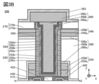
- 3A and 3B are cross-sectional views showing an example of a semiconductor device.
- FIG. 4 is a cross-sectional view showing an example of a semiconductor device.
- 5A to 5D are cross-sectional views showing an example of a method for manufacturing a semiconductor device.
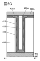
- 6A to 6D are cross-sectional views showing an example of a method for manufacturing a semiconductor device.
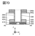
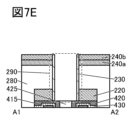
- 7A to 7F are cross-sectional views showing an example of a method for manufacturing a semiconductor device.
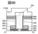
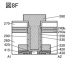
- 8A to 8F are cross-sectional views showing an example of a method for manufacturing a semiconductor device.
- 9A and 9B are cross-sectional views showing an example of a semiconductor device.
- 10A and 10B are cross-sectional views showing an example of a semiconductor device.
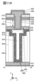
- 11A and 11B are cross-sectional views showing an example of a semiconductor device.
- 12A and 12B are cross-sectional views showing an example of a semiconductor device.
- 13A is a plan view illustrating an example of a semiconductor device
- FIG 13B is a cross-sectional view illustrating an example of the semiconductor device.
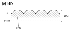
- FIG. 14A, 14B, 14C, and 14D are conceptual diagrams illustrating cross sections of an oxide semiconductor layer.
- FIG. 15 is a diagram illustrating the crystal structure of HfO 2 disclosed in Non-Patent Document 2.
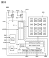
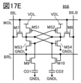
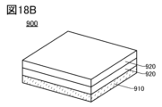
- FIG. 16 is a block diagram illustrating a configuration example of a semiconductor device. 17A to 17E are diagrams for explaining examples of the circuit configuration of a memory cell. 18A and 18B are perspective views illustrating a configuration example of a semiconductor device.
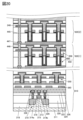
- FIG. 19 is a cross-sectional view showing an example of a semiconductor device.
- FIG. 20 is a cross-sectional view showing an example of a semiconductor device.
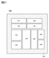
- FIG. 21 is a block diagram illustrating the CPU. 22A and 22B are perspective views of a semiconductor device.
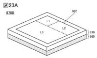
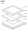
- 23A and 23B are perspective views of a semiconductor device.
- 24A and 24B are diagrams showing various storage devices by hierarchical level.
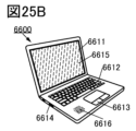
- 25A and 25B are diagrams showing an example of electronic equipment
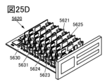
- FIGS. 25C to 25E are diagrams showing an example of a mainframe computer.
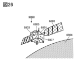
- FIG. 26 is a diagram showing an example of space equipment.
- FIG. 27 is a diagram illustrating an example of a storage system that can be applied to a data center.
- ordinal numbers “first” and “second” are used for convenience and do not limit the number of components or the order of the components (e.g., process order or stacking order).
- an ordinal number attached to a component in one place in this specification may not match an ordinal number attached to the same component in another place in this specification or in the claims.
- film and “layer” can be interchanged depending on the circumstances.
- the term “conductive layer” can be changed to the term “conductive film”.
- the term “insulating film” can be changed to the term “insulating layer”.
- the term “conductor” can be interchanged with the term “conductive layer” or the term “conductive film” depending on the circumstances.
- the term “insulator” can be interchanged with the term “insulating layer” or the term “insulating film” depending on the circumstances.
- oxide semiconductor can be interchanged with the term “oxide semiconductor layer” or the term “oxide semiconductor film” depending on the circumstances.
- parallel refers to a state in which two straight lines are arranged at an angle of -10 degrees or more and 10 degrees or less. Therefore, it also includes cases in which the angle is -5 degrees or more and 5 degrees or less.
- approximately parallel refers to a state in which two straight lines are arranged at an angle of -30 degrees or more and 30 degrees or less.
- Perfect refers to a state in which two straight lines are arranged at an angle of 80 degrees or more and 100 degrees or less. Therefore, it also includes cases in which the angle is 85 degrees or more and 95 degrees or less.
- approximately perpendicular refers to a state in which two straight lines are arranged at an angle of 60 degrees or more and 120 degrees or less.
- Openings include, for example, grooves, slits, and recesses. Also, the area in which an opening is formed may be referred to as an opening.
- drawings used in this specification show cases where the sidewalls of the insulator at the opening in the insulator are perpendicular or approximately perpendicular to the substrate surface or the surface on which the insulator is formed, but they may also be tapered.
- a tapered shape refers to a shape in which at least a portion of the side of the structure is inclined relative to the substrate surface or the surface on which the structure is to be formed.
- the angle between the inclined side and the substrate surface or the surface on which the structure is to be formed (hereinafter, sometimes referred to as the taper angle) is less than 90° in a region.
- the side of the structure and the substrate surface do not necessarily need to be completely flat, and may be approximately planar with a slight curvature, or approximately planar with minute irregularities.
- a reverse tapered shape refers to a shape with a side or top that protrudes in a direction parallel to the substrate more than the bottom.
- equal height refers to a configuration in which the heights from a reference surface (for example, a flat surface such as a substrate surface) are equal in cross-sectional view.
- a planarization process typically a chemical mechanical polishing (CMP) process
- CMP chemical mechanical polishing
- the surfaces treated in the CMP process have a configuration in which the heights from the reference surface are equal.
- the heights of multiple layers may differ depending on the processing device, processing method, or material of the processed surface during the CMP process. In this specification, this case is also treated as "equal height”.
- first layer and a second layer when there are two layers (here, a first layer and a second layer) with different heights relative to the reference surface, and the difference in height between the top surface of the first layer and the top surface of the second layer is 20 nm or less, this is also referred to as "equal height".
- side edges coincide means that at least a portion of the contours of the stacked layers overlap when viewed in a plane. For example, this includes cases where the upper and lower layers are processed using the same mask pattern, or where a portion of the mask pattern is the same. However, strictly speaking, the contours may not overlap, and the contour of the upper layer may be located inside the contour of the lower layer, or the contour of the upper layer may be located outside the contour of the lower layer, in which case it is also referred to as "side edges coincide”.
- the first film thickness and the second film thickness being the same means that the absolute value of the difference between the first film thickness and the second film thickness divided by the first film thickness is 0.1 or less. Alternatively, it means that the absolute value of the difference between the first film thickness and the second film thickness divided by the second film thickness is 0.1 or less.
- distance A and distance B are the same means that the absolute value of the difference between distance A and distance B divided by distance A is 0.1 or less. Alternatively, it means that the absolute value of the difference between distance A and distance B divided by distance B is 0.1 or less.
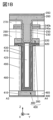
- FIGS. 1A to 2C are plan views and cross-sectional views of a semiconductor device including a transistor 200 and a capacitor 400.
- FIG. 2A is a plan view of the semiconductor device.
- FIG. 1A is a cross-sectional view of a portion indicated by a dashed line A1-A2 in FIG. 2A.
- FIG. 1B is a cross-sectional view of a portion indicated by a dashed line A3-A4 in FIG. 2A.
- FIG. 2B is a cross-sectional view of a portion of the transistor 200 in the XY plane in FIG.
- FIG. 2C is a cross-sectional view of a portion of the capacitor 400 in the XY plane in FIG. 2A. Note that some elements are omitted from the plan view of FIG. 1A for clarity.
- FIGS. 3A and 3B are enlarged views of the transistor 200 shown in FIG. 1A.
- FIG. 4 is an enlarged view of the capacitor 400 shown in FIG. 1B.
- FIG. 2D is a circuit diagram of the semiconductor device shown in FIGS. 1 and 2.
- arrows indicating the X-direction, Y-direction, and Z-direction may be used.
- the "X-direction” refers to the direction along the X-axis, and may not distinguish between the forward direction and the reverse direction unless otherwise specified. The same applies to the "Y-direction” and "Z-direction”.
- the X-direction, Y-direction, and Z-direction are directions that intersect with each other.
- the X-direction, Y-direction, and Z-direction are directions that are perpendicular to each other.
- one of the X-direction, Y-direction, and Z-direction may be called the "first direction” or “first direction”.
- the other may be called the “second direction” or “second direction”.
- the remaining one may be called the "third direction” or "third direction”.
- the semiconductor device shown in Figures 1A and 1B has an insulator 440 on a substrate (not shown), an insulator 485 and a conductor 410 on the insulator 440, an insulator 480 and a capacitor 400 on the insulator 485 and the conductor 410, a transistor 200 on the capacitor 400, an insulator 280 on the insulator 480, an insulator 270 on the insulator 280, and an insulator 283 on the transistor 200.
- the insulators 440, 485, 480, 280, and 270 function as interlayer insulating films.
- the insulator 440 also functions as a base insulator.
- the transistor 200 has a conductor 220 on the capacitor 400, a conductor 240 on the insulator 280, an oxide semiconductor 230 in contact with the conductor 220 and the conductor 240, an insulator 250 on the oxide semiconductor 230 and the insulator 270, and a conductor 260 on the insulator 250.
- the conductor 240 also has a conductor 240a and a conductor 240b on the conductor 240a.
- the capacitor 400 has a conductor 415 on the conductor 410, an insulator 430 on the conductor 415, and a conductor 420 on the insulator 430.
- An insulator 425 is provided on the conductor 420.
- the conductor 260 functions as a gate electrode
- the insulator 250 functions as a gate insulator
- the conductor 220 functions as one of the source electrode and the drain electrode
- the conductor 240 functions as the other of the source electrode and the drain electrode.
- the transistor 200 preferably uses a metal oxide (also called an oxide semiconductor) that functions as a semiconductor for the oxide semiconductor 230 including the channel formation region.
- a metal oxide also called an oxide semiconductor
- OS transistor a transistor using an oxide semiconductor in a channel formation region, such as the transistor 200, may be referred to as an OS transistor.
- insulator 280, conductor 240a, conductor 240b, and conductor 220 have openings 290 that reach insulator 425 and conductor 420.
- the bottom of opening 290 is the top surfaces of insulator 425 and conductor 420.
- the side walls of opening 290 are the side surfaces of insulator 280, conductor 240a, conductor 240b, and conductor 220.
- Opening 290 includes an opening in insulator 280, an opening in conductor 240a, an opening in conductor 240b, and an opening in conductor 220.
- the opening that the insulator 280 has in the area where it overlaps with the insulator 425 and the conductor 420 is part of the opening 290
- the opening that the conductor 240a has in the area where it overlaps with the insulator 425 and the conductor 420 is another part of the opening 290
- the opening that the conductor 240b has in the area where it overlaps with the insulator 425 and the conductor 420 is another part of the opening 290
- the opening that the conductor 220 has in the area where it overlaps with the insulator 425 and the conductor 420 is another part of the opening 290.
- At least some of the components of the transistor 200 are disposed in the opening 290.
- the oxide semiconductor 230, the insulator 250, and the conductor 260 are each disposed such that at least a portion of each of them is located in the opening 290.
- the portions of the oxide semiconductor 230, the insulator 250, and the conductor 260 that are arranged in the opening 290 are provided to reflect at least a part of the shape of the opening 290. That is, the oxide semiconductor 230 is provided in contact with the sidewall of the opening 290, the insulator 250 is provided to cover the oxide semiconductor 230, and the conductor 260 is provided to fill the recess of the insulator 250 that reflects the shape of the opening 290.
- the transistor 200 has a configuration in which one of the source electrode and drain electrode (here, conductor 220) is located on the bottom and the other of the source electrode and drain electrode (here, conductor 240) is located on the top, so that current flows in the vertical direction.
- a channel is formed along the side of the opening 290 of the insulator 280. Therefore, the transistor that is one embodiment of the present invention can be called a vertical channel transistor or a VFET (Vertical Field Effect Transistor).
- the conductor 420 functions as one of a pair of electrodes (sometimes called the upper electrode), the conductor 415 functions as the other of the pair of electrodes (sometimes called the lower electrode), and the insulator 430 functions as a dielectric.
- the capacitance element 400 constitutes a MIM (Metal-Insulator-Metal) capacitance.
- the insulator 480 has an opening 490 that reaches the conductor 410. At least a portion of each of the conductor 415, the insulator 430, the conductor 420, and the insulator 425 is disposed within the opening 490.
- the conductor 415, the insulator 430, and the conductor 420 are stacked along the shape of the opening 490.
- the capacitance element 400 having such a configuration can be called a trench type capacitance or trench capacitance.
- the insulator 425 is preferably provided so as to fill a recess that reflects the shape of the opening 490 of the conductor 420.
- the capacitive element 400 is configured such that the upper electrode and the lower electrode face each other across a dielectric not only on the bottom surface but also on the side surfaces of the opening 490, allowing the capacitance per unit area to be increased. Therefore, the deeper the opening 490, the greater the capacitance of the capacitive element 400 can be. Increasing the capacitance per unit area of the capacitive element 400 in this way can stabilize the read operation of the memory device. It can also promote miniaturization or high integration of memory devices.
- the transistor 200 is provided so as to overlap with the capacitor 400. Furthermore, the opening 290 in which part of the structure of the transistor 200 is provided has a region that overlaps with the opening 490 in which part of the structure of the capacitor 400 is provided.
- the conductor 260 overlaps with the insulator 425. It is also preferable that the bottom surface of the insulator 250 contacts the top surface of the insulator 425.
- the bottom surface of the conductor 220 contacts the top surface of the conductor 420. This allows electrical connection between one of the source electrode and drain electrode of the transistor 200 and the top electrode of the capacitance element 400.
- the transistor 200 and the capacitor 400 shown in this embodiment can be used as memory cells of a storage device (hereinafter, sometimes referred to as memory cell 450).
- a circuit diagram of the memory cell 450 is shown in FIG. 2D.
- one of the source and drain of the transistor 200 is connected to one electrode of the capacitor 400.
- the other of the source and drain of the transistor 200 is connected to a wiring BIL.
- the gate of the transistor 200 is connected to a wiring WOL.
- the other electrode of the capacitor 400 is connected to a wiring CAL.
- the wiring BIL corresponds to the conductor 240 (conductor 240a and conductor 240b), the wiring WOL corresponds to the conductor 260, and the wiring CAL corresponds to the conductor 410.
- the conductor 260 is provided extending in the Y direction, and the conductor 240 is provided extending in the X direction.
- the wiring BIL and the wiring WOL are provided intersecting each other.
- the wiring CAL (conductor 410) is provided extending in the X direction, but the present invention is not limited to this.
- the wiring CAL may be provided extending in the Y direction, or may be provided in a planar shape.
- the memory cell 450 reduces the area occupied by the transistor 200 and the capacitor 400 by overlapping them.
- the transistor and the capacitor are overlapped in this way, the transistor and the capacitor are arranged in an overlapping manner, which may cause parasitic capacitance and reduce the operating speed of the memory element. Therefore, in this embodiment, an insulator 425 is provided between the conductor 260 and the conductor 420, increasing the distance between the conductor 260 and the conductor 420 in most of the area where the conductors 260 and 420 overlap. This makes it possible to reduce the parasitic capacitance between the gate of the transistor 200 and the upper electrode of the capacitor 400. Therefore, the operating speed of the memory cell 450 consisting of the transistor 200 and the capacitor 400 can be improved.
- the oxide semiconductor 230 included in the transistor 200 is formed along a sidewall of the opening 290.
- the oxide semiconductor 230 is in contact with the side surface of the conductor 240a on the opening 290 side, the side surface of the conductor 240b on the opening 290 side, the side surface of the insulator 280 on the opening 290 side, and the side surface of the conductor 220 on the opening 290 side.
- the oxide semiconductor 230 is not formed so as to cover the bottom surface of the opening 290, and has a cylindrical shape with an opening in the center. It can be said that at least a part of the bottom surface of the oxide semiconductor 230 is removed in the opening 290.
- the oxide semiconductor 230 is formed in a sidewall shape with respect to the opening 290. Therefore, the insulator 250 is disposed in contact with the inner side surface of the oxide semiconductor 230, and at the bottom surface of the opening 290, the insulator 250 is in contact with the upper surface of the conductor 420 and the upper surface of the insulator 425. Furthermore, the oxide semiconductor 230 is not formed to cover the conductor 240b, and is not in contact with the upper surface of the conductor 240b. Here, the upper end of the oxide semiconductor 230 may coincide or roughly coincide with the upper surface of the conductor 240b.
- a parasitic capacitance is formed between the oxide semiconductor at the bottom of the opening 290 and the conductor 420.
- a parasitic capacitance is also formed between the oxide semiconductor at the bottom of the opening 290 and the conductor 260.
- the oxide semiconductor 230 is not formed at the bottom of the opening 290. Therefore, the parasitic capacitance between the oxide semiconductor 230 and the conductor 420, and the parasitic capacitance between the oxide semiconductor 230 and the conductor 260 can be suppressed. This makes it possible to form a transistor with good frequency characteristics and improve the operating speed of the semiconductor device.
- the oxide semiconductor 230 has a source region and a drain region formed on either side of the channel formation region.
- One of the source region and the drain region includes at least a part of the region of the oxide semiconductor 230 that is in contact with the conductor 240.
- the other of the source region and the drain region includes at least a part of the region of the oxide semiconductor 230 that is in contact with the conductor 220.
- the channel formation region of the transistor 200 is located in the region of the oxide semiconductor 230 between the conductor 220 and the conductor 240. It can also be said that the channel formation region of the transistor 200 is located in the region of the oxide semiconductor 230 that is in contact with the insulator 280 or in a region nearby the region.
- the channel length of the transistor 200 is the distance between the source region and the drain region. In other words, it can be said that the channel length of the transistor 200 is determined by the thickness of the insulator 280 on the conductor 220.
- the channel length L of the transistor 200 is indicated by a dashed double-headed arrow. In a cross-sectional view, the channel length L is the distance between the end of the region where the oxide semiconductor 230 and the conductor 220 contact each other and the end of the region where the oxide semiconductor 230 and the conductor 240 contact each other. It can also be said that the channel length L corresponds to the distance between the upper surface of the conductor 220 and the lower surface of the conductor 240a in a cross-sectional view.
- FIG. 2B A cross-sectional view of the XY plane in the region between the conductor 220 and the conductor 240 is shown in FIG. 2B.
- the oxide semiconductor 230, the insulator 250, and the conductor 260 are arranged concentrically inside the opening 290 of the insulator 280. Therefore, the side surface of the conductor 260 arranged in the center faces the side surface of the oxide semiconductor 230 via the insulator 250. In other words, in the region between the conductor 220 and the conductor 240, the entire circumference of the oxide semiconductor 230 becomes the channel formation region.
- the conductor 220 is not formed with the opening 290 penetrating it and the upper surface of the conductor 220 is formed with a flat shape, the insulator 250 is formed on the conductor 220, and the lower surface of the conductor 260 is higher than the upper surface of the conductor 220.
- the contact between the oxide semiconductor 230 and the conductor 220 becomes bottom contact that is mainly performed on the lower surface of the oxide semiconductor 230.
- the concentric structure of the oxide semiconductor 230, the insulator 250, and the conductor 260 shown in FIG. 2B is no longer formed.
- an offset region is formed in the oxide semiconductor 230 in the vicinity of the conductor 220, which may cause a decrease in the electrical characteristics of the transistor, such as the on-current, subthreshold swing value (hereinafter sometimes referred to as S value), field effect mobility, and frequency characteristics.
- S value the on-current, subthreshold swing value
- the height of the bottom surface of the conductor 260 is lower than the height of the top surface of the conductor 220 in the region that does not overlap with the opening 290.
- the contact between the oxide semiconductor 230 and the conductor 220 is a side contact that is mainly made on the side surface of the oxide semiconductor 230.
- the oxide semiconductor 230, the insulator 250, and the conductor 260 can be arranged concentrically even in the region near the conductor 220. That is, in the region near the conductor 220, the side surfaces of the conductor 260 and the oxide semiconductor 230 can be arranged to face each other through the insulator 250. Therefore, even in the vicinity of the conductor 220, the electric field of the conductor 260 functioning as a gate electrode can be sufficiently applied to the oxide semiconductor 230. This makes it possible to suppress the formation of an offset region in the oxide semiconductor 230 near the conductor 220. In this way, the electrical characteristics of the transistor 200, such as the on-current, the S value, the field effect mobility, and the frequency characteristics, can be improved.
- the channel length is limited by the exposure limit of lithography, making further miniaturization difficult.
- the channel length can be set by the film thickness of the insulator 280 on the conductor 220. Therefore, the channel length L of the transistor 200 can be, for example, 1 ⁇ m or less, 500 nm or less, 100 nm or less, 60 nm or less, 50 nm or less, 40 nm or less, 30 nm or less, 20 nm or less, or 10 nm or less, and 0.1 nm or more, 1 nm or more, or 5 nm or more.
- the channel length L a very fine structure below the exposure limit of lithography, the on-current, S value, frequency characteristics, and the like of the transistor 200 can be improved. Also, for example, by increasing the channel length L, DIBL (Drain Induced Barrier Lowering) can be suppressed in the transistor 200, and electrical characteristics can be improved.
- DIBL Drain Induced Barrier Lowering
- a channel formation region, a source region, and a drain region can be formed in the opening 290.
- the channel length L can be made larger than the width in the X direction and the width in the Y direction of the transistor 200. This allows the semiconductor device to be highly integrated.
- the semiconductor device of one embodiment of the present invention is used for a memory device, the memory capacity per unit area can be increased.
- the channel width of the transistor 200 is determined by the maximum width of the opening 290 (the maximum diameter if the opening 290 is circular in plan view).
- the maximum width D of the opening 290 is indicated by a double-headed arrow with two dots and dashes.
- the channel width W of the transistor 200 is indicated by a double-headed arrow with one dot and dashes.
- the maximum width D of the opening 290 is limited by the exposure limit of the lithography.
- the maximum width D of the opening 290 is set by the film thickness of each of the oxide semiconductor 230, the insulator 250, and the conductor 260 provided in the opening 290.
- the maximum width D of the opening 290 is, for example, 5 nm or more, 10 nm or more, or 20 nm or more, and is preferably 100 nm or less, 60 nm or less, 50 nm or less, 40 nm or less, or 30 nm or less.
- the maximum width D of the opening 290 corresponds to the diameter of the opening 290, and the channel width W can be calculated as "D x ⁇ ".
- the oxide semiconductor 230, the insulator 250, and the conductor 260 are arranged concentrically. This makes the distance between the conductor 260 and the oxide semiconductor 230 roughly uniform, so that a gate electric field can be applied roughly uniformly to the oxide semiconductor 230.
- the opening 290 is circular in plan view, but the present invention is not limited to this.
- the opening 290 may be approximately circular such as an ellipse, polygonal such as a rectangle, or polygonal such as a rectangle with rounded corners in plan view.
- the maximum width of the opening 290 can be calculated appropriately according to the shape of the top of the opening 290. For example, if the opening is rectangular in plan view, the maximum width of the opening 290 can be considered to be the length of the diagonal line at the top of the opening 290.
- the sidewalls of the opening 290 are perpendicular or approximately perpendicular to the upper surface of the insulator 440. With such a configuration, it is possible to miniaturize or highly integrate the semiconductor device.
- the opening 290 is provided so that the sidewall of the opening 290 is perpendicular to the top surface of the conductor 220, but the present invention is not limited to this.
- the sidewall of the opening 290 may not be strictly perpendicular and may have a tapered shape.
- the taper angle formed by the side surface of the insulator 280, which is part of the sidewall of the opening 290, and the top surface of the conductor 220 (which may be the top surface of the insulator 480 or the top surface of the insulator 440) is preferably 90 degrees or close to 90 degrees.
- the taper angle is preferably 75 degrees or more and 90 degrees or less.
- the taper angle may be less than 75 degrees, less than 70 degrees, less than 65 degrees, or less than 60 degrees.
- the metal oxides described in the section [Metal Oxides] below can be used in a single layer or a multilayer structure.
- the composition close thereto includes a range of ⁇ 30% of the desired atomic ratio. It is also preferable to use one or more of gallium, aluminum, and tin as the element M.
- the oxide semiconductor 230 may be configured not to include the element M.
- the metal oxide used as the oxide semiconductor 230 may be an In-Zn oxide.
- indium oxide may be used as the oxide semiconductor 230.
- the oxide semiconductor 230 may also be configured to include a trace amount of the element M.
- the composition of the metal oxide used in the oxide semiconductor 230 can be analyzed using, for example, energy dispersive X-ray spectroscopy (EDX), X-ray photoelectron spectroscopy (XPS), inductively coupled plasma mass spectrometry (ICP-MS), or inductively coupled plasma-atomic emission spectrometry (ICP-AES).
- EDX energy dispersive X-ray spectroscopy
- XPS X-ray photoelectron spectroscopy
- ICP-MS inductively coupled plasma mass spectrometry
- ICP-AES inductively coupled plasma-atomic emission spectrometry
- a combination of these techniques may be used for the analysis.
- the actual content may differ from the content obtained by analysis due to the influence of analytical accuracy. For example, if the content of element M is low, the content of element M obtained by analysis may be lower than the actual content.
- the metal oxide can be formed preferably by sputtering or atomic layer deposition (ALD).
- ALD atomic layer deposition
- the composition of the formed metal oxide may differ from the composition of the sputtering target.
- the zinc content in the formed metal oxide may decrease to about 50% compared to the sputtering target.
- Examples of the ALD method include the Thermal ALD method, in which the reaction between the precursor and reactant is carried out using only thermal energy, and the Plasma Enhanced ALD (PEALD) method, in which a plasma-excited reactant is used.
- Thermal ALD method in which the reaction between the precursor and reactant is carried out using only thermal energy
- PEALD Plasma Enhanced ALD
- the ALD method can deposit atoms one layer at a time, and therefore has the following advantages: extremely thin films can be formed; films can be formed on structures with high aspect ratios or surfaces with large steps; films can be formed with few defects such as pinholes; films can be formed with excellent coverage; and films can be formed at low temperatures.
- the PEALD method may be preferable because it uses plasma, which allows films to be formed at lower temperatures.
- some precursors used in the ALD method contain elements such as carbon or chlorine.
- films formed by the ALD method may contain more elements such as carbon or chlorine than films formed by other film formation methods. Note that the quantification of these elements can be performed using XPS or SIMS.
- the metal oxide film formation method of one embodiment of the present invention uses the ALD method, but adopts one or both of the conditions of a high substrate temperature during film formation and the implementation of an impurity removal process, so that the amount of carbon and chlorine contained in the film may be smaller than when the ALD method is used without applying these.
- the ALD method is a film formation method in which a film is formed by a reaction on the surface of a workpiece, unlike a film formation method in which particles released from a target are deposited. Therefore, it is a film formation method that is not easily affected by the shape of the workpiece and has good step coverage.
- the ALD method has excellent step coverage and excellent thickness uniformity, making it suitable for coating the surface of an opening with a high aspect ratio.
- the ALD method since the ALD method has a relatively slow film formation speed, it may be preferable to use it in combination with other film formation methods such as a sputtering method or a CVD method, which have a fast film formation speed.
- the metal oxide has a layered structure of a first metal oxide and a second metal oxide
- a method of forming a film of the first metal oxide using a sputtering method and forming a film of the second metal oxide on the first metal oxide using an ALD method can be mentioned.
- the first metal oxide has a crystal part
- the second metal oxide may grow as a crystal with the crystal part as a nucleus.
- the ALD method can control the composition of the resulting film by the amount of raw material gas introduced.
- the ALD method can form a film of any composition by adjusting the amount of raw material gas introduced, the number of times it is introduced (also called the number of pulses), the time required for one pulse (also called the pulse time), and the like.
- the ALD method can form a film whose composition changes continuously by changing the raw material gas while forming the film.
- the time required for film formation can be shortened compared to forming a film using multiple film formation chambers because no time is required for transportation and pressure adjustment. Therefore, the productivity of semiconductor devices can be increased in some cases.
- the method for forming the oxide semiconductor film that becomes the oxide semiconductor 230 is not particularly limited.
- the oxide semiconductor film may be formed using a CVD method, an MBE method, a PLD method, or the like.
- the crystallinity of the semiconductor material used for the oxide semiconductor 230 is not particularly limited, and any of an amorphous semiconductor (a semiconductor having an amorphous structure), a single crystal semiconductor (a semiconductor having a single crystal structure), or a semiconductor having crystallinity other than single crystal (a microcrystalline semiconductor, a polycrystalline semiconductor, or a semiconductor having a crystalline region in part) may be used.
- a single crystal semiconductor or a semiconductor having crystallinity is preferable because it can suppress deterioration of the transistor characteristics.
- the oxide semiconductor 230 preferably has a metal oxide layer having crystallinity.
- a metal oxide having crystallinity examples include a CAAC (c-axis aligned crystal) structure, a polycrystalline (Poly-crystal) structure, and a nanocrystalline (nc: nano-crystal) structure.
- CAAC c-axis aligned crystal
- Poly-crystal polycrystalline
- nc nanocrystalline
- the CAAC structure is a crystal structure in which multiple microcrystals (typically multiple IGZO microcrystals) have a c-axis orientation and are connected without being oriented in the a-b plane.
- the OS film having a CAAC structure can also be said to have a structure having layered crystal parts.
- the polycrystalline structure has grain boundaries.
- tiny gaps also called nanocracks or microcracks
- tiny spaces also called nanospaces or microspaces
- the electrical resistance of the oxide semiconductor layer increases. This is because the electrical resistance of the tiny gaps or tiny spaces is very high, for example, infinite.
- the contact resistance between the oxide semiconductor layer and one or both of the source electrode and the drain electrode increases. This adversely affects the initial characteristics or reliability of the transistor.
- the CAAC structure has fewer grain boundaries in the a-b plane than the polycrystalline structure, and therefore can realize a highly reliable semiconductor device.
- the crystallinity of the oxide semiconductor 230 can be analyzed, for example, by X-ray diffraction (XRD), a transmission electron microscope (TEM), or electron diffraction (ED). Alternatively, the analysis may be performed by combining a plurality of these techniques.
- XRD X-ray diffraction
- TEM transmission electron microscope
- ED electron diffraction
- the oxide semiconductor 230 may have a laminated structure of multiple oxide layers with different chemical compositions. For example, it may have a structure in which multiple types of metal oxides selected from those described in the [Metal Oxide] section below are appropriately laminated.
- the oxide semiconductor 230 can have a stacked structure of two or more metal oxide layers with different crystallinity.
- the two or more metal oxide layers may have different compositions or may have the same or approximately the same composition.
- the oxide semiconductor 230 may have a two-layer structure of an oxide semiconductor 230a and an oxide semiconductor 230b inside the oxide semiconductor 230a.
- the two-layer structure can be formed by forming a metal oxide film to be the oxide semiconductor 230a and then forming a metal oxide film to be the oxide semiconductor 230b thereon.
- the oxide semiconductor 230b can have a structure having a region with higher crystallinity than the oxide semiconductor 230a.
- the oxide semiconductor 230b can have a structure having a region with lower crystallinity than the oxide semiconductor 230a. Note that when the oxide semiconductor 230b has a region with lower crystallinity than the oxide semiconductor 230a, the oxide semiconductor 230b is formed and then subjected to heat treatment (also referred to as crystallization treatment) to increase the crystallinity of the oxide semiconductor 230b.
- heat treatment also referred to as crystallization treatment
- the oxide semiconductor 230b by forming the oxide semiconductor 230b on the oxide semiconductor 230a having high crystallinity, it is also easy to improve the crystallinity of the oxide semiconductor 230b. This makes it possible to improve the crystallinity of the entire oxide semiconductor 230, which is preferable.
- gallium, aluminum, or tin as the element M.
- two layers of IGZO having different compositions may be stacked.
- a laminated structure of any one selected from indium oxide, indium gallium oxide, and IGZO and any one selected from IAZO, IAGZO, and ITZO (registered trademark) may be used.
- the oxide semiconductor 230 may also have a stacked structure of three or more layers. As shown in FIG. 3B, the oxide semiconductor 230 disposed inside the opening 290 may have a three-layer structure having, for example, an oxide semiconductor 230c in contact with the sidewall of the opening 290, an oxide semiconductor 230a in contact with the side surface of the oxide semiconductor 230c on the central side of the opening 290, and an oxide semiconductor 230b in contact with the side surface of the oxide semiconductor 230a on the central side of the opening 290.
- the above-mentioned configuration can be applied to the oxide semiconductor 230a and the oxide semiconductor 230b.
- the oxide semiconductor 230c located on the outer side of the oxide semiconductor 230a can have the same configuration as that applicable to the oxide semiconductor 230b.
- the oxide semiconductor 230b and the oxide semiconductor 230c preferably have a larger band gap than the oxide semiconductor 230a.
- the oxide semiconductor 230a is sandwiched between the oxide semiconductor 230b and the oxide semiconductor 230c, which have a larger band gap, and the oxide semiconductor 230a mainly functions as a current path (channel).
- sandwiching the oxide semiconductor 230a between the oxide semiconductor 230b and the oxide semiconductor 230c it is possible to reduce the trap level at the interface of the oxide semiconductor 230a and its vicinity.
- a buried channel type transistor in which the channel is away from the insulating layer interface can be realized, and the field effect mobility can be increased.
- the influence of the interface state that may be formed on the back channel side is reduced, and the light deterioration of the transistor (for example, negative bias light deterioration) can be suppressed, and the reliability of the transistor can be improved.
- the thickness of the oxide semiconductor 230 is preferably 3 nm or more and 200 nm or less, more preferably 3 nm or more and 100 nm or less, more preferably 5 nm or more and 100 nm or less, more preferably 10 nm or more and 100 nm or less, more preferably 10 nm or more and 70 nm or less, more preferably 15 nm or more and 70 nm or less, more preferably 15 nm or more and 50 nm or less, and more preferably 20 nm or more and 50 nm or less.
- the thickness of the oxide semiconductor 230 is preferably 1 nm or more, 3 nm or more, or 5 nm or more, and 20 nm or less, 15 nm or less, 12 nm or less, or 10 nm or less.
- the oxide semiconductor layer when forming the oxide semiconductor layer, it is preferable to use two types of film formation methods, a sputtering method and an ALD method. For example, if a first oxide semiconductor layer having a CAAC structure is formed by a sputtering method and then a second oxide semiconductor layer having a lower crystallinity than the CAAC structure is formed by an ALD method, it is expected that the atomic layer of the second oxide semiconductor layer fills or repairs the gaps in the atomic-level crystal parts of the CAAC structure of the first oxide semiconductor layer. In addition, it is preferable to perform heat treatment (for example, 100° C. or more and 500° C. or less, preferably 200° C. or more and 450° C. or less, more preferably 300° C.
- heat treatment for example, 100° C. or more and 500° C. or less, preferably 200° C. or more and 450° C. or less, more preferably 300° C.
- the second oxide semiconductor layer (in other words, each crystal molecule formed by the ALD method) repairs the gaps in the atomic-level crystal parts of the CAAC structure of the first oxide semiconductor layer by the heat treatment.
- an oxide semiconductor layer formed using the above two types of film formation methods may be called a hybrid OS.
- Figures 14A, 14B, 14C, and 14D are conceptual diagrams for explaining a cross section of an oxide semiconductor layer having a CAAC structure.
- the c-axis is indicated by an arrow in each figure.
- the oxide semiconductor layer 370a shown in FIG. 14A has a region 372a and a region 372b located between the regions 372a.
- the region 372a corresponds to a region of a CAAC structure (i.e., a structure having layered crystal portions), and the region 372b corresponds to a region between the CAAC structures.
- the CAAC structure has fewer grain boundaries in the a-b plane than the polycrystalline structure. Thus, even in the oxide semiconductor layer 370a having a CAAC structure, there may be a minute gap or minute space between the crystal portions (region 372b in FIG. 14A).
- an oxide semiconductor layer having a CAAC structure is formed by sputtering as the first oxide semiconductor layer, and then an oxide semiconductor layer having a microcrystalline structure or an amorphous structure, which has lower crystallinity than the CAAC structure, is formed by ALD as the second oxide semiconductor layer.
- an oxide semiconductor layer having a region 372a is formed by sputtering as a first oxide semiconductor layer, and then an oxide semiconductor layer having a region 372c with lower crystallinity than the CAAC structure is formed by ALD as a second oxide semiconductor layer.
- the oxide semiconductor layer 370b has regions 372a and 372c. Since the ALD method can deposit atoms one layer at a time, the second oxide semiconductor layer can be formed to fill region 372b.
- the oxide semiconductor layer 370c has a region 372a and a region 372c.
- the 14C is a region having higher crystallinity or a higher density of crystal parts than the region 372a shown in FIG. 14B.
- the crystallinity of either or both of the regions 372a and 372c can be increased.
- the region 372c has, for example, a crystal part that has the same crystal structure as the crystal part of the region 372a.
- the region 372c has, for example, a crystal part that is connected to the crystal part of the region 372a.
- the oxide semiconductor layer 370d has a region 372a.
- the region 372a has improved crystallinity compared to the region 372a shown in FIG. 14B and FIG. 14C, and the boundary between the region 372a and the region 372c disappears, or the boundary between the region 372a and the region 372c is no longer observed. Therefore, the entire oxide semiconductor layer 370d has a CAAC structure.
- FIG. 14D when the entire oxide semiconductor layer 370d has a CAAC structure, a highly reliable semiconductor device can be realized. The presence or absence of the boundary between the region 372a and the region 372c can be confirmed, for example, by using a cross-sectional TEM, a cross-sectional STEM, or the like.
- the minute gap or the minute space in the first oxide semiconductor layer can be filled by forming a second oxide semiconductor layer on the first oxide semiconductor layer or by forming a second oxide semiconductor layer and performing heat treatment.
- a dense oxide semiconductor layer with increased crystallinity can be obtained.
- the dense oxide semiconductor layer with increased crystallinity is used for the channel formation region of a transistor, it is expected that an increase in the electrical resistance of the oxide semiconductor layer can be suppressed or the initial characteristics (particularly the on-current) of the transistor can be improved, making the transistor suitable for high-speed driving.
- the oxide semiconductor layer is formed by both the sputtering method and the ALD method, if the thickness of the oxide semiconductor layer formed by the ALD method is thin, the oxide semiconductor layer can be regarded as a single-layer structure, not a stacked structure of the oxide semiconductor layer formed by the sputtering method and the oxide semiconductor layer formed by the ALD method.
- the oxide semiconductor layer formed by the ALD method when the thickness of the oxide semiconductor layer formed by the ALD method is more than 0 nm and less than 3 nm, preferably more than 0 nm and less than 2 nm, and more preferably more than 0 nm and less than 1 nm, the oxide semiconductor layer formed by the two film formation methods, the sputtering method and the ALD method, can be regarded as a single-layer structure.
- the oxide semiconductor layer formed by the ALD method exceeds 3 nm, the oxide semiconductor layer formed by the sputtering method and the oxide semiconductor layer formed by the ALD method can be regarded as a stacked structure, a multilayer structure, or a multiple structure.
- the compositions are different from each other.
- the metal oxide film formed using the sputtering method has a composition suitable for forming a CAAC structure.
- the metal oxide film formed using the ALD method has a composition with a higher amount of indium than the metal oxide film formed using the sputtering method.
- the oxide semiconductor 230c by the ALD method.
- the vicinity of the surface on which the oxide semiconductor 230a is to be formed is prevented from being alloyed, and the crystallinity of the oxide semiconductor 230a can be further improved.
- the oxide semiconductor layer formed using the above two types of film formation methods can be considered to have a structure in which the gaps in the crystal parts of the CAAC structure are filled with atomic layers formed by the ALD method.
- This structure can be analyzed by analytical methods such as cross-sectional SEM, cross-sectional STEM, cross-sectional TEM, SIMS, and EDX.
- an oxide semiconductor layer having a CAAC structure formed using the above-mentioned two types of film formation methods may have a higher dielectric constant, film density, and film hardness than an oxide semiconductor layer having a CAAC structure formed using one type of film formation method.
- a transistor having excellent characteristics for example, a transistor with a large on-current, a transistor with high field-effect mobility, a transistor with a small S value, a transistor with high frequency characteristics (also called f characteristics), a highly reliable transistor, etc.
- the hydrogen concentration in the channel formation region of an oxide semiconductor measured by secondary ion mass spectrometry is preferably less than 1 ⁇ 10 20 atoms/cm 3 , more preferably less than 5 ⁇ 10 19 atoms/cm 3, still more preferably less than 1 ⁇ 10 19 atoms/cm 3, still more preferably less than 5 ⁇ 10 18 atoms/cm 3 , still more preferably less than 1 ⁇ 10 18 atoms/cm 3 , and still more preferably less than 1 ⁇ 10 17 atoms/cm 3 .
- the insulator 440 provided under the capacitor 400 and the insulator 283 provided over the transistor 200 use a barrier insulator against hydrogen.
- the insulator 440 and the insulator 283 can be provided to sandwich the memory cell 450.
- the insulator 440 and the insulator 283 provided on the outside of the transistor 200 including the oxide semiconductor 230 have a barrier property against hydrogen, so that the diffusion of hydrogen into the oxide semiconductor 230 can be suppressed.
- a barrier insulator refers to an insulator having barrier properties.
- the barrier properties refer to a property that a corresponding substance is difficult to diffuse (also referred to as a property that a corresponding substance is difficult to permeate, a property that the permeability of a corresponding substance is low, or a function of suppressing the diffusion of a corresponding substance).
- hydrogen refers to at least one of, for example, a hydrogen atom, a hydrogen molecule, and a substance bonded to hydrogen such as a water molecule and OH ⁇ .
- impurities when impurities are described as a corresponding substance, they refer to impurities in a channel formation region or a semiconductor layer unless otherwise specified, and refer to at least one of, for example, a hydrogen atom, a hydrogen molecule, a water molecule, a nitrogen atom, a nitrogen molecule, a nitrogen oxide molecule (N 2 O, NO, NO 2 , etc.), a copper atom, etc.
- oxygen when oxygen is described as a corresponding substance, it refers to at least one of, for example, an oxygen atom, an oxygen molecule, etc.
- Barrier insulators against hydrogen include aluminum oxide, magnesium oxide, hafnium oxide, gallium oxide, silicon nitride, and silicon oxide-nitride.
- the insulator 440 and the insulator 283 contain silicon and nitrogen.
- Silicon nitride which can be used as insulator 440 and insulator 283, has barrier properties against hydrogen if the film thickness is, for example, 2 nm or more.
- the silicon nitride film thickness is preferably 3 nm or more, and more preferably 5 nm or more.
- Silicon nitride has barrier properties against oxygen if the film thickness is, for example, 1 nm or more.
- the silicon nitride film thickness is preferably 2 nm or more. In other words, silicon nitride formed to a film thickness that has barrier properties against hydrogen also has barrier properties against oxygen.
- an insulator 480b having a function of trapping or fixing hydrogen is preferably used for the upper part of the insulator 480.
- the hydrogen concentration in the oxide semiconductor 230 located inside the insulator 440 and the insulator 283 can be reduced.
- hydrogen in the oxide semiconductor 230 is trapped or fixed by the insulator 480b, so that the hydrogen concentration in the insulator 480b is high.
- the hydrogen concentration of the insulator 480b obtained by SIMS may be 1 ⁇ 10 19 atoms/cm 3 or more or 1 ⁇ 10 20 atoms/cm 3 or more.
- the hydrogen concentration of at least a part of the insulator 480b is higher than the hydrogen concentration of the oxide semiconductor 230.
- the oxide semiconductor 230 has a region in which the hydrogen concentration is lower than the hydrogen concentration of the insulator 480b.
- the ability to capture or adhere to the corresponding substance can also be said to have the property of making the corresponding substance less likely to diffuse. Therefore, the ability to capture or adhere to the corresponding substance can be rephrased as barrier properties.
- a metal oxide containing hafnium or the like e.g., hafnium oxide, etc.
- the above metal oxide preferably has oxygen atoms with dangling bonds.
- Such metal oxides may have the property of capturing or fixing hydrogen with dangling bonds.
- the above metal oxide preferably has an amorphous structure. This is because in metal oxides with an amorphous structure, some oxygen atoms have dangling bonds.
- the above metal oxide preferably has an amorphous structure, but crystalline regions may be formed in some parts. Furthermore, the above metal oxide may have crystal grain boundaries in some parts.
- hafnium silicate an oxide containing hafnium and silicon (hereinafter, sometimes referred to as hafnium silicate) tends to have an amorphous structure. Therefore, hafnium silicate has the property of capturing or adhering hydrogen, making it suitable as insulator 480b. In this case, insulator 480b contains hafnium, silicon, and oxygen.
- oxides containing hafnium are listed as insulators having the function of capturing or fixing hydrogen, but the present invention is not limited to this.
- oxides containing magnesium, oxides containing aluminum, oxides containing aluminum and hafnium (hafnium aluminate), etc. may be listed.
- the above metal oxides may further contain oxides containing zirconium.
- oxides containing hafnium and zirconium, etc. are listed.
- it is preferable that these metal oxides have silicon added and have an amorphous structure.
- the insulator 280 is provided to cover the conductor 220, the conductor 420, and the insulator 430, and is in contact with the side surface of the oxide semiconductor 230 and the bottom surface of the conductor 240 (see Figures 1A and 1B).
- the insulator 280 is preferably formed using a material with a low relative dielectric constant. This allows the insulator 280 to function as an interlayer insulating film, thereby reducing the parasitic capacitance between the conductor 240 and the conductor 220. This allows the frequency characteristics of the transistor 200 to be improved.
- the insulator 280 a single layer or a stack of insulators containing a material with a low dielectric constant, as described in the [Insulator] section below, can be used. Specifically, silicon oxide or silicon oxynitride can be used as the insulator 280. Furthermore, it is preferable that the concentration of impurities such as water and hydrogen in the insulator 280 is reduced. This can suppress the intrusion of impurities such as water and hydrogen into the channel formation region of the oxide semiconductor 230.
- an insulator containing oxygen for the insulator 280.
- oxygen can be supplied to the oxide semiconductor 230 in contact with the insulator 280, making it easier to reduce oxygen vacancies.
- oxygen can be supplied to the oxide semiconductor 230.
- oxygen vacancies and VOH in the channel formation region of the oxide semiconductor 230 can be reduced, and a transistor with favorable electrical characteristics and high reliability can be obtained.
- the amount of released oxygen molecules from the insulator 280b is preferably equal to or greater than 1.0 ⁇ 10 14 molecules/cm 2 and less than 1.0 ⁇ 10 15 molecules/cm 2.
- the amount of released oxygen molecules can be measured by thermal desorption spectrometry.
- the channel length of the transistor 200 when the channel length of the transistor 200 is short, the influence of oxygen vacancies in the channel formation region and VOH on the electrical characteristics and reliability is particularly large. Therefore, by sufficiently reducing the hydrogen concentration in the oxide semiconductor 230 and then optimizing the amount of oxygen supplied to the oxide semiconductor 230, a transistor with a short channel length having favorable electrical characteristics and high reliability can be realized.
- the insulator 280 is preferably formed by a deposition method such as a sputtering method or a plasma enhanced chemical vapor deposition (PECVD) method.
- a deposition method such as a sputtering method or a plasma enhanced chemical vapor deposition (PECVD) method.
- PECVD plasma enhanced chemical vapor deposition
- oxygen supplied to the oxide semiconductor 230 for example, after forming the insulator 280, a heat treatment in an oxygen-containing atmosphere or a plasma treatment in an oxygen-containing atmosphere may be performed.
- oxygen may be supplied by forming an oxide film in an oxygen atmosphere on the upper surface of the insulator 280 by a sputtering method. The oxide film may then be removed. By performing such a treatment, oxygen can be supplied to the insulator 280, and the amount of oxygen supplied to the oxide semiconductor 230 can be increased.
- the insulator 280 can also be configured to use a barrier insulator against hydrogen.
- silicon nitride can be used for the insulator 280. With such a configuration, the diffusion of hydrogen into the oxide semiconductor 230 can be suppressed. Furthermore, it is preferable that the concentration of impurities such as water and hydrogen in the insulator 280 is reduced. This can suppress the intrusion of impurities such as water and hydrogen into the channel formation region of the oxide semiconductor 230.
- the insulator 280 is illustrated as having a single-layer structure, but is not limited thereto and may have a laminated structure.
- the insulator 280 may have a two-layer structure, with the height of the top surface of the first layer of insulator being the same as the height of the top surface of the conductor 220, and the second layer of insulator being provided on top of the first layer of insulator.
- the insulator 280 may have a layered structure of an insulator 280a, an insulator 280b on the insulator 280a, and an insulator 280c on the insulator 280b.
- Insulator 280a contacts the top surface of insulator 480, the side surface of insulator 430, the side surface of conductor 420, and the top and side surfaces of conductor 220.
- Insulator 280b contacts the top surface of insulator 280a and the bottom surface of insulator 280c.
- Insulator 280c contacts the bottom surface of conductor 240.
- an insulating material applicable to the insulator 280 described above may be used. Specifically, silicon oxide or silicon oxynitride may be used as the insulator 280b. In addition, it is preferable that the concentration of impurities such as water and hydrogen in the insulator 280b is reduced.
- insulator 280b When an insulator containing oxygen is used as insulator 280b, it is preferable to use a barrier insulator against oxygen as insulator 280a and insulator 280c, as described below in the section [Insulator].
- insulator 280a between insulator 280b and conductor 220 and conductor 420, excessive oxidation of conductor 220 and conductor 420, which would increase the resistance of conductor 220 and conductor 420, can be suppressed.
- insulator 280c between insulator 280b and conductor 240, excessive oxidation of conductor 240, which would increase the resistance of conductor 240, can be suppressed.
- the insulators 280a and 280c may each be a barrier insulator against hydrogen. This allows the insulator 280b to be sandwiched between the barrier insulators against hydrogen. This makes it possible to suppress the diffusion of hydrogen from below the insulator 280a or above the insulator 280c to the insulator 280b.
- the silicon nitride film and the silicon nitride oxide film each have the characteristics of releasing little impurities (e.g., water and hydrogen) from themselves and being difficult for oxygen and hydrogen to permeate, and therefore can be suitably used for the insulators 280a and 280c. Note that the insulators 280a and 280c may be made of the same material or different materials.
- an insulator having a function of capturing or fixing hydrogen may be used for one or both of the insulators 280a and 280c. With such a configuration, it is possible to suppress the diffusion of hydrogen from below the insulator 280a or above the insulator 280c to the insulator 280b, and further to capture or fix the hydrogen contained in the insulator 280b. Thus, it is possible to reduce the hydrogen concentration in the oxide semiconductor 230 and its vicinity.
- the insulator 280a magnesium oxide, aluminum oxide, hafnium oxide, or an oxide containing hafnium and silicon may be used.
- the insulator 280a may be a laminated film of aluminum oxide and silicon nitride on the aluminum oxide.
- the insulator 280c may be a laminated film of silicon nitride and aluminum oxide on the silicon nitride.
- silicon nitride can be used for insulators 280a and 280c
- silicon oxide can be used for insulator 280b.
- insulators 280a and 280c each contain at least silicon and nitrogen.
- Insulator 280b contains at least silicon and oxygen.
- FIG. 3A shows a configuration in which the insulator 280c is provided on the planarized insulator 280b, but the present invention is not limited to this.
- the insulator 280c may be formed without performing planarization treatment on the insulator 280b. By not performing planarization treatment, the manufacturing cost can be reduced and the productivity can be increased.
- the insulators 280a, 280b, and 280c can be formed successively without exposure to the atmospheric environment.
- the insulators 280a to 280c By forming the insulators 280a to 280c without exposing them to the atmospheric environment, it is possible to prevent impurities or moisture from the atmospheric environment from adhering to the insulators 280a to 280c, and it is possible to keep the vicinity of the interface between the insulators 280a and 280b, and the vicinity of the interface between the insulators 280b and 280c clean.
- the amount of oxygen supplied to the region of the oxide semiconductor 230 in contact with the insulator 280a and the region in contact with the insulator 280c is smaller than that to the region in contact with the insulator 280b. Therefore, the resistance of the region of the oxide semiconductor 230 in contact with the insulator 280a and the region in contact with the insulator 280c may be reduced.
- the film thickness of the insulator 280a the range of the region that functions as one of the source region and the drain region can be controlled.
- the film thickness of the insulator 280c the range of the region that functions as the other of the source region and the drain region can be controlled. Therefore, the film thicknesses of the insulators 280a and 280c can be appropriately set according to the characteristics required for the transistor 200.
- FIG. 3A shows the insulator 280 having a three-layer laminated structure
- the present invention is not limited to this.
- the insulator 280 may have a two-layer or four or more layer laminated structure.
- the insulator 270 is provided to cover the conductor 240 and the oxide semiconductor 230.
- the insulator 270 is preferably formed using a material with a low relative dielectric constant. As a result, the insulator 270 functions as an interlayer insulating film, and the parasitic capacitance between the conductor 260 and the conductor 240 can be reduced. This can improve the frequency characteristics of the transistor 200.
- the insulator 270 may be made of an insulating material that can be applied to the insulator 280 described above. Specifically, silicon oxide or silicon oxynitride can be used as the insulator 270. In addition, it is preferable that the concentration of impurities such as water and hydrogen in the insulator 270 is reduced.
- the insulator 270 can have a layered structure of the insulator 270a and the insulator 270b as shown in FIG. 3A. In this case, it is preferable that the insulator 270a is disposed in contact with the lower surface of the insulator 270b and the side surface on the opening 290 side.
- aluminum oxide may be used for the insulator 270a
- silicon oxide may be used for the insulator 270b.
- the insulator 270 covers the side edge of the oxide semiconductor 230, the side edge of the conductor 240a, and the side edge of the conductor 240b. This can prevent the conductor 260 from shorting out with the oxide semiconductor 230, the conductor 240a, and the conductor 240b.
- the conductor 240 preferably has a conductor 240a and a conductor 240b on the conductor 240a.
- the conductor 240a and the conductor 240b have an opening 290 that overlaps with the insulator 425.
- the conductor 240 is preferably not provided inside the opening of the insulator 280.
- the conductor 240 preferably does not have a region that contacts the side of the insulator 280 in the opening 290.
- the opening of the conductor 240 and the opening of the insulator 280 can be formed at the same time.
- the film thickness distribution of the oxide semiconductor 230 provided inside the opening 290 can be made uniform.
- the oxide semiconductor 230 can be prevented from being divided by the step between the conductor 240 and the insulator 280.
- FIG. 1A and 1B show a configuration in which the side surface of the conductor 240 in the opening 290 and the side surface of the insulator 280 in the opening 290 are flush with each other, but the present invention is not limited to this.
- the side surface of the conductor 240 in the opening 290 and the side surface of the insulator 280 in the opening 290 may be discontinuous.
- the inclination of the side surface of the conductor 240 in the opening 290 and the inclination of the side surface of the insulator 280 in the opening 290 may be different from each other.
- the angle formed between the side surface of the conductor 240 in the opening 290 and the upper surface of the insulator 440 is smaller than the angle formed between the side surface of the insulator 280 in the opening 290 and the upper surface of the insulator 440.
- the bottom surface of the conductor 240a contacts the insulator 280, one side surface contacts the oxide semiconductor 230, and the other side surface contacts the insulator 270.
- the conductor 240a is preferably made of a metal having a higher conductivity than the conductor 240b.
- the conductor 240a is preferably made of a metal having a lower sheet resistance than the conductor 240b. With this configuration, the conductor 240 including the conductor 240a can function as a wiring electrically connected to one of the source electrode or the drain electrode.
- the conductor 240a may be one or more of ruthenium, tantalum, nickel, titanium, molybdenum, tungsten, hafnium, vanadium, niobium, aluminum, chromium, copper, silver, gold, platinum, zinc, manganese, iron, cobalt, magnesium, zirconium, beryllium, indium, iridium, strontium, and lanthanum, or an alloy containing one or more of the above-mentioned metals.
- tungsten as the conductor 240a.
- a portion of the conductor 240a may contain a metal oxide of the above metal.
- a layer of the metal oxide may be formed near the interface of the conductor 240a with the conductor 240b and near the interface with the oxide semiconductor 230.
- ruthenium and ruthenium alloys are preferable because they are materials that maintain a relatively low electrical resistance even when oxidized.
- One of the side surfaces of the conductor 240b contacts the oxide semiconductor 230.
- the bottom surface of the conductor 240b contacts the conductor 240a.
- the other side surface of the conductor 240b contacts the insulator 270.
- the conductor 240b preferably has ohmic contact with the oxide semiconductor 230 and preferably has low contact resistance with the oxide semiconductor 230.
- the contact resistance between the conductor 240b and the oxide semiconductor 230 is preferably lower than the contact resistance between the metal layer used in the conductor 240a and the oxide semiconductor 230.
- the conductive oxide (OC: Oxide Conductor, also called conductive material containing oxygen) used for the conductor 240b is preferably a conductive oxide containing indium.
- the conductive oxide containing indium it is preferable to use indium oxide, indium tin oxide (sometimes called ITO), indium zinc oxide, indium tin oxide with added silicon (also called ITSO), etc.
- Indium oxide may contain tungsten or titanium, for example, In-W oxide, In-W-Zn oxide, In-Ti oxide, In-Ti-Sn oxide, etc.
- Conductive oxide containing zinc may also be used, for example, zinc oxide, zinc oxide with added gallium, In-Ga-Zn oxide, etc.
- Ruthenium oxide, oxide containing strontium and ruthenium, oxide containing lanthanum and nickel, etc. can be used as the conductive oxide.
- conductive oxide containing indium is preferable because of its high conductivity.
- indium tin oxide with silicon added may be used for the conductor 240b.
- the conductor 240b contains indium, tin, silicon, and oxygen.
- silicon By adding silicon to the indium tin oxide, the polycrystallization of the indium tin oxide can be suppressed.
- indium tin oxide with silicon added is likely to have an nc structure (nanocrystal structure) or an amorphous structure.
- Polycrystallized indium tin oxide may also be used for the conductor 240b. In this case, the conductor 240b contains indium, tin, and oxygen.
- conductor 240 has a two-layer laminate structure of conductor 240a and conductor 240b, but the present invention is not limited to this.
- Conductor 240 may have a laminate structure of three or more layers.
- a configuration in which conductor 240b is laminated on conductor 240a was shown, but the present invention is not limited to this.
- a configuration in which conductor 240a is laminated on conductor 240b may also be used.
- the conductor 220 is provided on the conductor 420 and the insulator 425, and can be formed into an island shape as shown in Figures 1A and 1B.
- the bottom surface of the conductor 220 is in contact with the top surface of the conductor 420, and one of the source and drain of the transistor 200 can be electrically connected to the top electrode of the capacitor 400.
- the conductors described in the [Conductor] section below can be used in a single layer or a stacked layer. It is preferable to use a conductive material that is not easily oxidized or a conductive material that has a function of suppressing the diffusion of oxygen as the conductor 220.
- the conductor 220 in contact with the oxide semiconductor 230 is preferably made of a conductive oxide. Therefore, the conductor 220 may be made of a conductive oxide that can be used for the conductor 240b, for example. For example, indium tin oxide with silicon added may be used for the conductor 220. In this case, the conductor 220 contains indium, tin, silicon, and oxygen. This allows the conductor 220 to make ohmic contact with the oxide semiconductor 230, and the contact resistance between the conductor 220 and the oxide semiconductor 230 can be reduced. This allows the on-current, field effect mobility, S value, and frequency characteristics of the transistor 200 to be improved.
- an opening 290 is preferably formed penetrating the conductor 220.
- the opening 290 By configuring the opening 290 so that the side surface of the conductor 220 and the oxide semiconductor 230 are in contact with each other, the area in which the conductor 220 and the oxide semiconductor 230 make ohmic contact can be increased, and the contact resistance between the conductor 220 and the oxide semiconductor 230 can be further reduced.
- the conductor 220 can have a layered structure of conductor 220a and conductor 220b on conductor 220a.
- a metal with high conductivity for conductor 220a it is preferable to use a metal with high conductivity for conductor 220a. Therefore, for conductor 220a, a metal that can be used for conductor 240a may be used. For example, tungsten may be used for conductor 220a.
- conductor 220b a conductive material that can be used for conductor 220 described above may be used for conductor 220. By using such a configuration, the conductivity of conductor 220 including conductor 220a can be improved.
- the insulator 250 is provided in contact with the insulator 270, the oxide semiconductor 230, the conductor 420, and the insulator 425. At the bottom surface of the opening 290, the insulator 250 is preferably in contact with the top surface of the conductor 420 and the top surface of the insulator 425. With this configuration, the conductor 260 overlaps with the insulator 425, and the distance between the conductor 260 and the conductor 420 can be increased to reduce the parasitic capacitance. Note that if the opening 490 is sufficiently larger than the opening 290, the entire bottom surface of the insulator 250 may be in contact with the insulator 425 and the insulator 250 may not be in contact with the conductor 420.
- the heights of the upper end of insulator 250 and the upper surface of insulator 270 can be the same or approximately the same, and insulator 250 can be configured not to be provided above insulator 270.
- the insulator 250 may have a layered structure of an insulator 250a, an insulator 250b on the insulator 250a, and an insulator 250c on the insulator 250b.
- the insulator 250a contacts the conductor 220, the oxide semiconductor 230, and the insulator 270.
- the insulator 250c contacts the conductor 260 and the insulator 283.
- the insulator 250b is provided between the insulator 250a and the insulator 250c.
- the insulators 250a and 250c are made of an insulator having a barrier property against oxygen. Furthermore, it is preferable that the insulators 250a and 250c are made of an insulator having a function of capturing or fixing hydrogen. As the insulators 250a and 250c, an insulating material that can be used for the insulator 480b may be used. By providing such insulators 250a and 250c, oxidation of the conductor 220 in contact with the insulator 250a and the conductor 260 in contact with the insulator 250c can be suppressed. Furthermore, the insulators 250a and 250c can more effectively capture or fix hydrogen contained in the oxide semiconductor 230 and its vicinity. Therefore, the hydrogen concentration in the oxide semiconductor 230 can be reduced.
- the insulator 250a aluminum oxide can be used as the insulator 250a, and hafnium oxide can be used as the insulator 250c.
- the insulators 250a and 250c may be made of the insulators described in the [Insulators] section below, either in a single layer or in a multilayer configuration.
- insulator 250a and insulator 250c are used as gate insulators, it is possible to reduce the gate potential applied during transistor operation while maintaining the physical thickness of the gate insulator. It is also possible to reduce the equivalent oxide thickness (EOT) of the insulator that functions as the gate insulator.
- EOT equivalent oxide thickness
- the insulator 250b is preferably made of silicon oxide or silicon oxynitride, which have a high dielectric strength. In order to improve the dielectric strength, the thickness of the insulator 250b may be made thicker than that of the insulator 250a. By providing such an insulator 250b, the dielectric strength of the insulator 250 can be improved and the leakage current can be reduced.
- an insulator 250d having a barrier property against hydrogen may be provided between the insulator 250c and the conductor 260. This can suppress the diffusion of impurities such as hydrogen contained in the conductor 260 to the oxide semiconductor 230.
- an insulator having a barrier property against hydrogen an insulator applicable to the insulator 440 and the insulator 283 can be used.
- silicon nitride is preferable because it has a high barrier property against hydrogen.
- the insulator 250d has a barrier property against hydrogen
- the insulator 250d also has a barrier property against oxygen. Therefore, by providing the insulator 250d, it is possible to prevent the conductor 260 from being excessively oxidized.
- the thickness of the insulators 250a to 250d is preferably 0.5 nm to 15 nm, more preferably 0.5 nm to 12 nm, and even more preferably 0.5 nm to 10 nm.
- the insulators 250a to 250d may have a region with the above thickness at least in part.
- the thickness of the insulator 250a may be 1 nm
- the thickness of the insulator 250b may be 2 nm
- the thickness of the insulator 250c may be 2 nm
- the thickness of the insulator 250d may be 1 nm.
- the thickness of the insulator 250 can be further reduced, and the S value of the transistor 200 can be reduced.
- the thickness of the insulators 250a to 250d is not limited to the above thickness.
- any one or more of the insulators 250a to 250d may be configured to have a thickness of 15 nm or more.
- the conductor 260 is provided in contact with the upper surface of the insulator 250. Also, as shown in Figures 1A and 1B, the portion of the conductor 260 above the insulator 270 can be extended in the Y direction to function as wiring.
- the conductor 260 may be a single layer or a multilayer of the conductors described in the section below titled "Conductor.”
- the conductor 260 may be a highly conductive material such as tungsten.
- a conductive material that is difficult to oxidize or a conductive material that has a function of suppressing the diffusion of oxygen.
- conductive materials include conductive materials that contain nitrogen (e.g., titanium nitride or tantalum nitride), and conductive materials that contain oxygen (e.g., ruthenium oxide). This can suppress a decrease in the conductivity of the conductor 260.
- the conductor 260 may have a laminated structure.
- the conductor 260 may have a laminated structure of a conductor 260a and a conductor 260b on the conductor 260a.
- titanium nitride may be used as the conductor 260a
- tungsten may be used as the conductor 260b.
- the conductor 260 is shown as having a two-layer laminate structure of conductor 260a and conductor 260b, but the present invention is not limited to this.
- the conductor 260 may also have a laminate structure of three or more layers.
- the conductor 260a and the conductor 260b may be provided only below the upper surface of the insulator 270, and the conductor 260c functioning as wiring may be provided on the conductor 260a and the conductor 260b.
- the height of the upper end of the conductor 260a and the upper surface of the conductor 260b coincides or approximately coincides with the height of the upper surface of the insulator 270.
- the conductor 260c functions as wiring, and therefore may be formed by extending in the Y direction, for example.
- the conductor 260c may be made of a conductive material that can be used as the conductor 260a or the conductor 260b.
- tungsten may be used for the conductor 260c.
- the conductor 260c may be made of a laminated structure of titanium nitride and tungsten.
- the insulator 283 is preferably a barrier insulator against hydrogen. This can prevent hydrogen from diffusing from above the insulator 283 to the oxide semiconductor 230. Silicon nitride films and silicon nitride oxide films each have the characteristics of releasing little impurities (e.g., water and hydrogen) from themselves and being less permeable to oxygen and hydrogen, and therefore can be suitably used for the insulator 283.
- impurities e.g., water and hydrogen
- the insulator 283 contains silicon and nitrogen.
- the sputtering method does not require the use of molecules containing hydrogen in the deposition gas, and therefore the hydrogen concentration in the insulator 283 can be reduced. Furthermore, by depositing the insulator 283 by sputtering, silicon nitride with high density can be formed.
- silicon nitride formed by the PEALD method may be used as the insulator 283.
- the conductor 260 can be covered with good coverage.
- This configuration can prevent hydrogen from diffusing from above the insulator 283 to the oxide semiconductor 230. Therefore, the hydrogen concentration in the oxide semiconductor 230 can be reduced.
- the capacitor 400 is provided in an opening 490 formed in an insulator 480.
- the capacitor 400 includes a conductor 415 on a conductor 410, an insulator 430 on the conductor 415, and a conductor 420 on the insulator 430.
- An insulator 425 is further formed on the conductor 420.
- the conductor 410 is preferably provided so as to be embedded inside an opening formed in the insulator 485.
- the conductor 410 and the insulator 485 are formed on the insulator 440.
- the insulator 480 is formed on the conductor 410 and the insulator 440.
- the insulator 480 has an opening 490 that reaches the conductor 410. At least a portion of the conductor 415 is disposed in the opening 490.
- the conductor 415 can be configured to have a region that contacts the upper surface of the conductor 410 in the opening 490, a region that contacts the side surface of the insulator 480 in the opening 490, and a region that contacts at least a portion of the upper surface of the insulator 480.
- the insulator 430 is disposed so that at least a portion of it is located in the opening 490.
- the conductor 420 is disposed so that at least a portion of it is located in the opening 490.
- the insulator 425 is disposed so that at least a portion of it is located in the opening 490.
- a conductor 415, an insulator 430, and a conductor 420 are layered along the sidewall of the opening 490 and the top surface of the conductor 410.
- An insulator 425 is provided to fill the recess in the conductor 420 that is formed to reflect the shape of the opening 490.
- the sidewalls of the opening 490 are preferably perpendicular to the top surface of the conductor 410.
- the opening 490 has a cylindrical shape. With this configuration, miniaturization or high integration of the semiconductor device can be achieved.
- the capacitance of the capacitor element 400 can be increased.
- the depth of the opening 490 can be set appropriately according to the capacitance required for the memory cell 450, but is preferably greater than the depth of the opening 290.
- the depth of the opening 490 can be set to 1.1 to 20 times the depth of the opening 290, preferably 2 to 10 times, and more preferably 3 to 5 times.
- the depth of the opening 490 can be defined as the distance between the top surface of the conductor 410 and the top surface of the insulator 480.
- the depth of the opening 290 can be defined as the distance between the top surface of the insulator 425 or the top surface of the conductor 420 and the top surface of the conductor 240b.
- opening 490 As shown in FIG. 2C, within opening 490, conductor 415, insulator 430, conductor 420, and insulator 425 are arranged concentrically.
- opening 490 By forming opening 490 so that it has a circular shape in a plan view, the distance between conductor 415 and conductor 420 becomes approximately uniform, so that an electric field can be applied approximately uniformly to insulator 430.
- the opening 490 is circular in plan view, but the present invention is not limited to this.
- the opening 490 may be approximately circular in plan view, such as an ellipse, polygonal in shape, such as a rectangle, or polygonal in shape, such as a rectangle, with rounded corners.
- the opening 490 is provided so that the sidewall of the opening 490 is perpendicular to the top surface of the conductor 410, but the present invention is not limited to this.
- the sidewall of the opening 490 may not be strictly perpendicular and may have a tapered shape.
- the taper angle between the side surface of the insulator 480, which is part of the sidewall of the opening 490, and the top surface of the conductor 410 (which may be the top surface of the insulator 440) is 90 degrees or close to 90 degrees.
- the taper angle is 75 degrees or more and 90 degrees or less.
- the capacitor 400 is preferably provided so as to overlap with the transistor 200.
- the opening 490 preferably has a region that overlaps with the opening 290.
- the insulator 425 is preferably provided so as to be in contact with the lower surface of the insulator 250.
- the diameter of opening 490 is larger than the diameter of opening 290, but this is not limited thereto, and the diameter of opening 490 can also be smaller than the diameter of opening 290. Also, the diameter of opening 490 can be the same as or approximately the same as the diameter of opening 290.
- a barrier insulator against hydrogen for the insulator 440.
- silicon nitride may be used as the insulator 440. With this configuration, it is possible to suppress the diffusion of impurities such as hydrogen from below the insulator 440 to the insulator 480, etc.
- the insulator 485 may be any insulator that can be used for the insulator 270 described above.
- the insulator 485 may be silicon oxide.
- the conductor 410 is provided on the insulator 440.
- the conductors described in the [Conductor] section can be used as the conductor 410, either in a single layer or in a laminated layer.
- a conductive material with high conductivity such as tungsten, can be used as the conductor 410.
- the conductivity of the conductor 410 can be improved, allowing it to function adequately as wiring.
- the conductor 410 is preferably made of a conductive material that is not easily oxidized or a conductive material that has a function of suppressing the diffusion of oxygen, in a single layer or a laminated layer.
- a conductive material that is not easily oxidized or a conductive material that has a function of suppressing the diffusion of oxygen, in a single layer or a laminated layer.
- titanium nitride or indium tin oxide with added silicon may be used.
- the conductor 410 may have a laminated structure of the conductor 410a and the conductor 410b.
- the conductor 410a can be formed in contact with the bottom surface and the side surface of the conductor 410b.
- titanium nitride may be used for the conductor 410a
- tungsten may be used for the conductor 410b.
- a structure in which a titanium nitride film is provided on the conductor 410b can be used.
- oxide insulators are used for the insulators 480 and 485, the conductor 410 can be prevented from being oxidized by the insulators 480 and 485.
- the insulator 480 functions as an interlayer film, it is preferable that it has a low dielectric constant. By using a material with a low dielectric constant as the interlayer film, the parasitic capacitance that occurs between wirings can be reduced.
- an insulator containing a material with a low dielectric constant, as described in the [Insulator] section, can be used in a single layer or a stacked layer. Silicon oxide and silicon oxynitride are preferable because they are thermally stable. In this case, the insulator 480 contains at least silicon and oxygen.
- the insulator 480 can have a layered structure of an insulator 480a and an insulator 480b on the insulator 480a.
- the insulator 480a may be an insulator containing a material with a low dielectric constant as described above (e.g., silicon oxide).
- the insulator 480b is preferably an insulator having a function of capturing or fixing hydrogen.
- hafnium silicate may be used as the insulator 480b.
- one or more of the layers of the insulator 480 may be configured to use an insulator having barrier properties against hydrogen, as described in the [Insulator] section. This can prevent hydrogen from diffusing from below through the insulator 480 to the insulator 430. Silicon nitride and silicon nitride oxide each have the characteristics of releasing little impurities (e.g., water and hydrogen) from themselves and being difficult for oxygen and hydrogen to permeate, and therefore can be suitably used for the insulator 480.
- impurities e.g., water and hydrogen
- the conductor 415 can be a single layer or a stack of conductors described in the [Conductor] section. It is preferable to use a conductive material that is not easily oxidized or a conductive material that has a function of suppressing the diffusion of oxygen as the conductor 415.
- a conductive material that is not easily oxidized or a conductive material that has a function of suppressing the diffusion of oxygen for example, titanium nitride or tantalum nitride can be used. Alternatively, for example, a structure in which tantalum nitride is stacked on titanium nitride may be used. With such a structure, when an oxide insulator is used for the insulator 430, the conductor 415 can be prevented from being oxidized by the insulator 430.
- the conductor 415 can be prevented from being oxidized by the insulator 480.
- this is not limited to the above, and tungsten or the like may be used for the conductor 415.
- the conductor 415 may be a structure in which tungsten is stacked on titanium nitride.
- the insulator 430 is provided on the conductor 415.
- the insulator 430 is provided so as to contact the upper surface and side surfaces of the conductor 415.
- the insulator 430 is structured so as to cover the side end portion of the conductor 415. This can prevent the conductor 415 and the conductor 420 from shorting out.
- the insulator 430 it is preferable to use a material with a high relative dielectric constant, so-called high-k material, as described in the [Insulator] section.
- high-k material a material with a high relative dielectric constant
- the insulator 430 can be made thick enough to suppress leakage current, and the capacitance of the capacitance element 400 can be sufficiently ensured.
- the insulator 430 is preferably made of a laminate of insulating layers made of a high-k material, and preferably has a laminate structure of a material with a high dielectric constant (high-k) and a material with a higher dielectric strength than the high-k material.
- the insulator 430 can be made of an insulating film laminated in the order of zirconium oxide, aluminum oxide, and zirconium oxide.
- the insulator can be made of an insulating film laminated in the order of zirconium oxide, aluminum oxide, zirconium oxide, and aluminum oxide.
- the insulator can be made of an insulating film laminated in the order of hafnium zirconium oxide, aluminum oxide, hafnium zirconium oxide, and aluminum oxide.
- an insulator with a relatively high dielectric strength, such as aluminum oxide in a laminated manner, the dielectric strength is improved and electrostatic breakdown of the capacitance element 400 can be suppressed.
- a material that can have ferroelectricity may be used as the insulator 430.
- materials that can have ferroelectricity include metal oxides such as hafnium oxide, zirconium oxide, and HfZrO x (X is a real number greater than 0).
- materials that can have ferroelectricity include materials in which an element J1 (here, the element J1 is one or more selected from zirconium, silicon, aluminum, gadolinium, yttrium, lanthanum, strontium, etc.) is added to hafnium oxide.
- the ratio of the number of atoms of hafnium atoms to the number of atoms of element J1 can be set appropriately, and for example, the ratio of the number of atoms of hafnium atoms to the number of atoms of element J1 can be set to 1:1 or close to 1:1.
- materials that can have ferroelectricity include materials in which an element J2 (here, the element J2 is one or more selected from hafnium, silicon, aluminum, gadolinium, yttrium, lanthanum, strontium, etc.) is added to zirconium oxide.
- the ratio of the number of zirconium atoms to the number of atoms of element J2 can be set appropriately, for example, the ratio of the number of zirconium atoms to the number of atoms of element J2 can be set to or near 1: 1.
- piezoelectric ceramics having a perovskite structure such as lead titanate (PbTiO x ), barium strontium titanate (BST), strontium titanate, lead zirconate titanate (PZT), strontium bismuthate tantalate (SBT), bismuth ferrite (BFO), and barium titanate, may be used.
- examples of materials that may have ferroelectricity include metal nitrides having element M1, element M2, and nitrogen.
- element M1 is one or more selected from aluminum, gallium, indium, etc.
- element M2 is one or more selected from boron, scandium, yttrium, lanthanum, cerium, neodymium, europium, titanium, zirconium, hafnium, vanadium, niobium, tantalum, chromium, etc. It should be noted that the ratio of the number of atoms of element M1 to the number of atoms of element M2 can be set appropriately. Also, metal oxides having element M1 and nitrogen may have ferroelectricity even if they do not contain element M2.
- examples of materials that may have ferroelectricity include materials in which element M3 is added to the above metal nitride.
- element M3 is one or more selected from magnesium, calcium, strontium, zinc, cadmium, etc.
- the ratio of the number of atoms of element M1, the number of atoms of element M2, and the number of atoms of element M3 can be set appropriately.
- examples of materials that can have ferroelectricity include perovskite-type oxynitrides such as SrTaO 2 N and BaTaO 2 N, and GaFeO 3 having a ⁇ -alumina structure.
- metal oxides and metal nitrides are given as examples, but the present invention is not limited to these.
- metal oxynitrides in which nitrogen is added to the above-mentioned metal oxides, or metal oxynitrides in which oxygen is added to the above-mentioned metal nitrides, etc. may also be used.
- a material that can have ferroelectricity for example, a mixture or compound made of multiple materials selected from the materials listed above can be used.
- the insulator 430 can have a layered structure made of multiple materials selected from the materials listed above.
- the crystal structure (characteristics) of the materials listed above can change not only depending on the film formation conditions but also on various processes, in this specification, not only materials that exhibit ferroelectricity are called ferroelectrics, but also materials that can have ferroelectricity.
- the film thickness of the insulator 430 can be 100 nm or less, preferably 50 nm or less, more preferably 20 nm or less, and even more preferably 10 nm or less (typically 2 nm to 9 nm).
- the film thickness is preferably 8 nm to 12 nm.
- a layer of a material that can have ferroelectricity may be referred to as a ferroelectric layer, a metal oxide film, or a metal nitride film.
- a device having such a ferroelectric layer, a metal oxide film, or a metal nitride film may be referred to as a ferroelectric device in this specification, etc.
- metal oxides containing one or both of hafnium and zirconium are preferable because they can have ferroelectricity even in a small area.
- the ferroelectricity can be maintained even if the area (occupied area) in a plan view of the ferroelectric layer is 100 ⁇ m 2 or less, 10 ⁇ m 2 or less, 1 ⁇ m 2 or less, or 0.1 ⁇ m 2 or less.
- the ferroelectricity may be maintained even if the area is 10,000 nm 2 or less, or 1,000 nm 2 or less.
- the ferroelectricity may be maintained.
- a ferroelectric is an insulator that has the property that polarization occurs inside when an electric field is applied from the outside, and that the polarization remains even when the electric field is made zero. For this reason, a non-volatile memory element can be formed using a capacitance element (hereinafter sometimes referred to as a ferroelectric capacitor) that uses this material as a dielectric.
- a non-volatile memory element that uses a ferroelectric capacitor is sometimes called a FeRAM (Ferroelectric Random Access Memory), a ferroelectric memory, etc.
- a ferroelectric memory has a transistor and a ferroelectric capacitor, and one of the source and drain of the transistor is electrically connected to one terminal of the ferroelectric capacitor. Therefore, when a ferroelectric capacitor is used as the capacitance element 400, the semiconductor device shown in this embodiment functions as a ferroelectric memory.
- Ferroelectricity is believed to be manifested by the displacement of oxygen or nitrogen in the crystals contained in the ferroelectric layer by an external electric field. It is also presumed that the manifestation of ferroelectricity depends on the crystal structure of the crystals contained in the ferroelectric layer. Therefore, in order for the insulator 430 to manifest ferroelectricity, the insulator 430 must contain crystals. In particular, it is preferable for the insulator 430 to contain crystals having an orthorhombic crystal structure, since ferroelectricity is manifested.
- the crystal structure of the crystals contained in the insulator 430 may be one or more selected from the cubic, tetragonal, orthorhombic, monoclinic, and hexagonal crystal systems.
- the insulator 430 may have an amorphous structure. In this case, the insulator 430 may be a composite structure having an amorphous structure and a crystalline structure.
- hafnium oxide which is one of the materials that can be used for the insulator 430.
- hafnium oxide is known to have various crystal structures.
- FIG. 15 shows crystal structures such as monoclinic (space group: P2 1 /c), orthorhombic (space group: Pbca or Pca2 1 ), tetragonal (space group: P4 2 /nmc), and cubic (space group: Fm-3m) that hafnium oxide can have, and their respective polarization-electric field characteristics.
- each of the above-mentioned crystal structures can undergo a phase change. The same is true for hafnium zirconium oxide.
- hafnium oxide the monoclinic, tetragonal, and cubic crystal structures have an inversion center. Therefore, hafnium oxide containing crystals having these crystal structures is a paraelectric substance that does not have remanent polarization.
- the orthorhombic crystal structure having a space group of Pca2 1 does not have a central symmetry. Therefore, in the orthorhombic crystal structure having a space group of Pca2 1 , oxygen is displaced by an external electric field, so that ferroelectricity is expressed in hafnium oxide containing crystals having an orthorhombic crystal structure having a space group of Pca2 1. The same is true for hafnium zirconium oxide.
- the conductor 420 is provided in contact with the upper surface of the insulator 430.
- the conductors described in the [Conductor] section can be used as the conductor 420 in a single layer or a stacked layer. It is preferable to use a conductive material that is not easily oxidized or a conductive material that has a function of suppressing the diffusion of oxygen as the conductor 420.
- a conductive material that is not easily oxidized or a conductive material that has a function of suppressing the diffusion of oxygen as the conductor 420.
- titanium nitride or tantalum nitride can be used.
- Alternatively, for example, a structure in which tantalum nitride is stacked on titanium nitride may be used.
- the conductor 420 when oxide insulators are used for the insulators 430 and 425, the conductor 420 can be prevented from being oxidized by the insulators 430 and 425. Furthermore, when an oxide conductor is used for the conductor 220, the conductor 420 can be prevented from being oxidized by the conductor 220. However, this is not limited thereto, and a conductor such as tungsten may be used for the conductor 415.
- the insulator 430 and the conductor 420 coincide with each other.
- the insulator 430 and the conductor 420 can be formed using the same mask.
- the conductor 220, the insulator 430, and the conductor 420 can be formed using the same mask.
- the insulator 425 is provided in contact with the conductor 420 and the insulator 250. It is preferable that the upper surface of the insulator 425 is flush with the upper surface of the conductor 420. This configuration can improve the flatness of the surface on which the insulator 250 is formed, and can prevent the insulator 250 from having gaps or voids.
- the insulator 425 preferably has a low dielectric constant.
- a single layer or a multilayer of insulators containing a material with a low dielectric constant as described in the [Insulator] section can be used. Silicon oxide and silicon oxynitride are preferred because they are thermally stable. In this case, the insulator 425 contains at least silicon and oxygen.
- the distance between the conductor 260 and the conductor 420 can be increased. This reduces the parasitic capacitance of the gate of the transistor 200 and the upper electrode of the capacitance element 400. This improves the operating speed of the memory cell 450 consisting of the transistor 200 and the capacitance element 400.
- insulating materials for forming insulators, conductive materials for forming conductors, or semiconductor materials for forming semiconductors can be formed as films using a sputtering method, a chemical vapor deposition (CVD) method, a molecular beam epitaxy (MBE) method, a pulsed laser deposition (PLD) method, an ALD method, or the like, as appropriate.
- CVD chemical vapor deposition
- MBE molecular beam epitaxy
- PLD pulsed laser deposition
- ALD ALD method
- Sputtering methods include RF sputtering, which uses a high-frequency power supply as the sputtering power source, DC sputtering, which uses a direct current power supply, and pulsed DC sputtering, which changes the voltage applied to the electrodes in a pulsed manner.
- RF sputtering is mainly used when depositing insulating films
- DC sputtering is mainly used when depositing metal conductive films.
- Pulsed DC sputtering is mainly used when depositing compounds such as oxides, nitrides, and carbides using the reactive sputtering method.
- CVD methods can be classified into plasma CVD (PECVD) methods, which use plasma, thermal CVD (TCVD: Thermal CVD) methods, which use heat, and photo CVD (Photo CVD) methods, which use light. They can also be further divided into metal CVD (MCVD: Metal CVD) methods and metal organic CVD (MOCVD: Metal CVD) methods, depending on the source gas used.
- PECVD plasma CVD
- TCVD Thermal CVD
- Photo CVD Photo CVD
- MCVD Metal CVD
- MOCVD Metal CVD
- the plasma CVD method can produce high-quality films at relatively low temperatures. Furthermore, because the thermal CVD method does not use plasma, it is a film formation method that can reduce plasma damage to the workpiece. For example, wiring, electrodes, elements (transistors, capacitive elements, etc.) included in a semiconductor device may become charged up by receiving electric charge from the plasma. At this time, the accumulated electric charge may destroy the wiring, electrodes, elements, etc. included in the semiconductor device. On the other hand, with the thermal CVD method, which does not use plasma, such plasma damage does not occur, and the yield of semiconductor devices can be increased. Furthermore, with the thermal CVD method, no plasma damage occurs during film formation, so films with fewer defects can be obtained.
- the ALD method can be a thermal ALD method in which the reaction between the precursor and reactant is carried out using only thermal energy, or a PEALD method in which a plasma-excited reactant is used.
- the CVD and ALD methods are different from sputtering methods in which particles emitted from a target or the like are deposited. Therefore, they are film formation methods that are less affected by the shape of the workpiece and have good step coverage.
- the ALD method has excellent step coverage and excellent thickness uniformity, making it suitable for coating the surfaces of openings with high aspect ratios.
- the ALD method has a relatively slow film formation speed, it may be preferable to use it in combination with other film formation methods such as the CVD method, which has a faster film formation speed.
- a film of any composition can be formed by changing the flow rate ratio of the raw material gases.
- a film with a continuously changing composition can be formed by changing the flow rate ratio of the raw material gases while forming the film.
- a film of any composition can be formed by introducing multiple different types of precursors.
- a film of any composition can be formed by controlling the number of cycles of each precursor.
- the type of oxidizing agent may be changed depending on each precursor.
- ozone (O 3 ) may be used as an oxidizing agent for the first precursor
- oxygen (O 2 ) may be used as an oxidizing agent for the second precursor.
- a heat treatment may be performed.
- the heat treatment may be performed under reduced pressure, and the film may be formed continuously without exposure to the atmosphere. By performing such a treatment, it is possible to remove moisture and hydrogen adsorbed on the surface on which the film is to be formed, and further reduce the moisture concentration and hydrogen concentration in the structure on which the film is to be formed.
- the temperature of the heat treatment is preferably 100°C or higher and 600°C or lower.
- a substrate (not shown) is prepared, and an insulator 440 is formed on the substrate (see FIG. 5A).
- the insulator 440 may be formed by a sputtering method, a CVD method, an MBE method, a PLD method, an ALD method, or the like, as appropriate.
- a silicon nitride film can be formed as the insulator 440 by a sputtering method.
- the conductor 410 is formed on the insulator 440 (see FIG. 5A).
- the conductor 410 is preferably formed so as to be embedded in the insulator 485 as shown in FIG. 1B.
- the conductor 410 and the insulator 485 can be made of the materials described above.
- an opening is formed in the insulator 485, a conductive film that will become the conductor 410 is formed so as to fill the opening, and the upper part of the conductive film is removed by CMP processing, and the conductor 410 is formed in the opening.
- the conductive films that become the insulator 485 and the conductor 410 may be formed by a sputtering method, a CVD method, an MBE method, a PLD method, an ALD method, or the like, as appropriate.
- a silicon oxide film can be formed as the insulator 485 by a sputtering method.
- a titanium nitride film can be formed as the conductive film that becomes the conductor 410a by an ALD method or a CVD method
- a tungsten film can be formed as the conductive film that becomes the conductor 410b by a CVD method.
- the insulator 480 is formed on the conductor 410 (see FIG. 5A).
- the insulator 480 may be formed from any of the insulating materials described above.
- the insulator 480 may be formed by a sputtering method, a CVD method, an MBE method, a PLD method, an ALD method, or the like.
- the insulator 480 may be formed by forming a silicon oxide film by a CVD method using an organic silane gas (e.g., TEOS (Tetra-Ethyl-Ortho-Silicate)) and then forming a silicon oxide film thereon by a sputtering method.
- an organic silane gas e.g., TEOS (Tetra-Ethyl-Ortho-Silicate)
- the insulator 480 with a large film thickness can be formed with good productivity. Furthermore, by using a sputtering method that does not require the use of molecules containing hydrogen in the film formation gas, the hydrogen concentration can be reduced in the layer of the insulator 480 close to the oxide semiconductor 230.
- silicon oxide can be deposited as the insulator 480a as described above, and hafnium silicate can be deposited as the insulator 480b by a sputtering method.
- a deposition target containing hafnium and silicon can be used.
- a co-sputtering method using a silicon oxide target and a hafnium oxide target can be used.
- the hydrogen concentration in the insulator 480 can be reduced, and the oxygen vacancy and VoH in the channel formation region of the oxide semiconductor 230 can be reduced.
- the opening 490 may be formed by using a lithography method.
- the method for manufacturing the opening 290 of the transistor 200 can be referred to.
- the opening 490 can be formed by dry etching or wet etching. Dry etching is suitable for forming the opening 490 with a high aspect ratio because it allows anisotropic etching. However, the opening 490 can also be formed by appropriately using dry etching and wet etching. For details about the dry etching and wet etching methods, the method of manufacturing the opening 290 of the transistor 200 can be referred to.
- CMP treatment on the insulator 480 after deposition to planarize the upper surface.
- planarization treatment on the insulator 480, the conductor 420 that functions as an electrode can be suitably formed. Note that the above-mentioned CMP treatment is not necessarily performed. By not performing the CMP treatment, the manufacturing process of the semiconductor device can be shortened, and manufacturing costs can be reduced.
- a conductive film that will become the conductor 415 is formed to cover the opening 490 and the insulator 480.
- the conductive film that will become the conductor 415 may be formed by a sputtering method, a CVD method, an MBE method, a PLD method, an ALD method, or the like, as appropriate.
- the conductive film is preferably formed in contact with the sidewall and bottom surface of the opening 490, which have a large aspect ratio.
- the conductive film is preferably formed by a film formation method that has good coverage, such as an ALD method or a CVD method.
- a titanium nitride film can be formed by an ALD method or a CVD method.
- conductor 415 is then processed using lithography to form conductor 415 (see FIG. 5C).
- conductor 415 is formed in contact with the sidewalls and bottom surface of opening 490.
- a portion of conductor 415 is formed on opening 490 and in contact with a portion of the top surface of insulator 480.
- a portion of the top surface of insulator 480 may be removed.
- the film thickness of the portion of insulator 480 that overlaps with conductor 415 may be thicker than the film thickness of the portion of insulator 480 that does not overlap with conductor 415.
- an insulating film 430A is formed on the conductor 415 and the insulator 480 (see FIG. 5D).
- the insulating film 430A is an insulating film that will become the insulator 430 in a later process.
- the insulating film 430A may be formed by a sputtering method, a CVD method, an MBE method, a PLD method, an ALD method, or the like, as appropriate. Since the insulating film 430A is formed inside the opening 490, which has a large aspect ratio, it is preferable to form the insulating film 430A by a film formation method with good coverage, such as an ALD method or a CVD method. For example, zirconium oxide, aluminum oxide, and zirconium oxide can be formed in this order by using the ALD method.
- the conductive film 420A is a conductive film that will become the conductor 420 in a later step.
- the conductive film 420A may be formed by a sputtering method, a CVD method, an MBE method, a PLD method, an ALD method, or the like, as appropriate. Since the conductive film 420A is formed inside the opening 490 with a large aspect ratio, it is preferable to form the conductive film 420A by a film formation method with good coverage, such as an ALD method or a CVD method. For example, titanium nitride can be formed by the ALD method or the CVD method. In addition, since the conductive film 420A is subjected to a CMP process in a later step, the conductive film 420A is preferably thicker than the conductor 415.
- Insulating film 425A is an insulating film that will become insulator 425 in a later process.
- the insulating film 425A may be formed by a sputtering method, a CVD method, an MBE method, a PLD method, an ALD method, or the like, as appropriate.
- insulating film 425A can be formed by depositing silicon oxide using a sputtering method.
- insulator 425 can function as an interlayer film with a small relative dielectric constant, as described above. Therefore, insulating film 425A may not be formed with good coverage inside opening 490, and voids may be formed in insulating film 425A inside opening 490.
- the insulating film 425A is subjected to a CMP process to remove the insulating film 425A above the conductive film 420A, and the insulator 425 is formed (see FIG. 6B).
- a CMP process By this CMP process, only the insulating film 425A inside the opening 490 remains, and becomes the insulator 425.
- This CMP process may be performed until the top surface of the conductive film 420A is exposed. At this time, a part of the top surface of the conductive film 420A may be removed. Also, a part of the insulating film 425A may remain in an area that does not overlap with the opening 490.
- a conductive film 220A is formed on the conductive film 420A and the insulator 425 (see FIG. 6C).
- the conductive film 220A is a conductive film that will become the conductor 220 in a later process.
- the conductive film 220A may be formed by a sputtering method, a CVD method, an MBE method, a PLD method, an ALD method, or the like, as appropriate.
- ITSO can be formed as the conductive film 220A by a sputtering method. Also, as shown in FIG.
- tungsten can be formed as the conductive film 220A by a sputtering method, and then ITSO can be formed by a sputtering method.
- the conductive film 220A, the conductive film 420A, and the insulating film 430A are processed into an island shape using lithography to form the conductor 220, the conductor 420, and the insulator 430 (see FIG. 6D).
- the conductive film 220A, the conductive film 420A, and the insulating film 430A can be processed by dry etching or wet etching. Processing by dry etching is suitable for fine processing. However, the above processing can also be performed by appropriately using dry etching and wet etching.
- the manufacturing process of the semiconductor device can be simplified and the manufacturing cost can be reduced. Note that this is not limited to this, and the conductor 220, the conductor 420, and the insulator 430 can also be processed using different masks.
- Figures 7A to 8F correspond to the transistor 200 in Figure 1A.
- Figure 7D corresponds to the transistor 200 in Figure 1B.
- the insulator 280 is formed on the insulator 480 and the conductor 220 (see FIG. 7A).
- the insulator 280 may be formed from any of the insulating materials described above.
- the insulator 280 may be formed by a sputtering method, a CVD method, an MBE method, a PLD method, an ALD method, or the like.
- the insulator 280 may have a structure including the insulators 280a, 280b, and 280c shown in FIG. 3A.
- silicon nitride may be formed as the insulator 280a by the PEALD method
- silicon oxide may be formed as the insulator 280b by the sputtering method
- silicon nitride may be formed as the insulator 280c by the sputtering method.
- the upper surface of the insulator 280 has an upwardly convex curved shape. By not performing the planarization process, it is possible to reduce manufacturing costs and increase production yields.
- planarization process is not necessarily performed after the insulators 280a to 280c are formed.
- the planarization process may be performed and then the insulator 280c may be formed.
- the insulator 280 when forming the insulator 280, a sputtering method can be used, which does not require the use of molecules containing hydrogen in the film formation gas, and the hydrogen concentration in the insulator 280 can be reduced.
- the insulator 280 in this manner, the amount of hydrogen diffusing from the insulator 280 to the oxide semiconductor 230 can be reduced, and oxygen vacancies and VoH in the channel formation region can be reduced.
- a conductive film 240A is formed on the insulator 280, and a conductive film 240B is formed on the conductive film 240A (see FIG. 7A).
- the conductive film 240A becomes the conductor 240a in a later process
- the conductive film 240B becomes the conductor 240b in a later process.
- the conductive film 240A and the conductive film 240B may be formed using any of the above-mentioned conductive materials as appropriate.
- the conductive film 240A and the conductive film 240B may be formed by a sputtering method, a CVD method, an MBE method, a PLD method, an ALD method, or the like as appropriate.
- tungsten can be formed as the conductive film 240A by sputtering.
- ITSO can be formed as the conductive film 240B by sputtering.
- the resist is first exposed through a mask.
- the exposed area is then removed or left using a developer to form a resist mask.
- etching is performed through the resist mask to process a conductor, semiconductor, or insulator into a desired shape.
- a resist mask can be formed by exposing the resist using KrF excimer laser light, ArF excimer laser light, or EUV (Extreme Ultraviolet) light.
- a liquid immersion technique may be used in which a liquid (e.g., water) is filled between the substrate and the projection lens for exposure.
- an electron beam or an ion beam may be used instead of the light described above.
- a mask may not be used.
- the resist mask that is no longer needed after processing can be removed by performing a dry etching process such as ashing using oxygen plasma (hereinafter sometimes referred to as oxygen plasma treatment), a wet etching process, a dry etching process followed by a wet etching process, or a wet etching process followed by a dry etching process.
- a dry etching process such as ashing using oxygen plasma (hereinafter sometimes referred to as oxygen plasma treatment), a wet etching process, a dry etching process followed by a wet etching process, or a wet etching process followed by a dry etching process.
- a configuration may be adopted in which an SOC (Spin On Carbon) film and an SOG (Spin On Glass) film are formed between the workpiece and the resist mask.
- SOC film and the SOG film are formed between the workpiece and the resist mask.
- a lithography method can be performed by forming an SOC film, an SOG film, and a resist mask in that order on the workpiece.
- a configuration may be adopted in which a hard mask made of an insulator or conductor is provided between the workpiece and the SOC film.
- an SOC film, an SOG film, and a resist mask can be formed in that order on the conductive film 240B, and the resist mask can be patterned into the shape of the opening 290.
- an etching gas containing halogen can be used, specifically, an etching gas containing one or more of fluorine, chlorine, and bromine can be used.
- an etching gas containing one or more of fluorine, chlorine, and bromine can be used.
- the etching gas C4F6 gas, C5F6 gas, C4F8 gas, CF4 gas, SF6 gas, CHF3 gas, CH2F2 gas, CH3F gas , Cl2 gas, BCl3 gas, SiCl4 gas, CCl4 gas, HBr gas, or BBr3 gas can be used alone or in a mixture of two or more gases.
- oxygen gas, carbon dioxide gas, nitrogen gas, helium gas, argon gas, hydrogen gas, or hydrocarbon gas can be appropriately added to the above etching gas.
- a gas containing no halogen gas and a hydrocarbon gas or a hydrogen gas can be used as the etching gas.
- the hydrocarbon used in the etching gas may be one or more of methane ( CH4 ), ethane ( C2H6 ), propane ( C3H8 ) , butane ( C4H10 ) , ethylene ( C2H4 ), propylene ( C3H6 ) , acetylene ( C2H2 ) , and propyne ( C3H4 ) .
- the etching conditions may be appropriately set depending on the object to be etched.
- a capacitively coupled plasma (CCP) etching apparatus having parallel plate electrodes can be used as the dry etching apparatus.
- a capacitively coupled plasma etching apparatus having parallel plate electrodes can be configured to apply a high-frequency voltage to one of the parallel plate electrodes. Or, it can be configured to apply a high-frequency voltage of the same frequency to each of the parallel plate electrodes. Also, it can be configured to apply multiple different high-frequency voltages to the parallel plate electrodes.
- Such a CCP etching apparatus is called a dual frequency capacitively coupled plasma (DF-CCP) etching apparatus. In the DF-CCP etching apparatus, it can be configured to apply high-frequency voltages of different frequencies to each of the parallel plate electrodes.
- DF-CCP dual frequency capacitively coupled plasma
- a configuration in which multiple different high-frequency voltages are applied to one of the parallel plate electrodes can be used.
- a dry etching device having a high-density plasma source can be used.
- ICP inductively coupled plasma
- the etching device can be appropriately set according to the object to be etched.
- reactive ion etching can be performed by applying a high-frequency voltage to the electrode on the substrate side in the above-mentioned dry etching device to generate a self-bias potential.
- reactive ion etching etching is performed by accelerating ion species in the plasma and colliding them with the workpiece, so that highly anisotropic etching can be performed.
- the following process of forming the opening 290 is performed continuously without exposure to the outside air.
- a multi-chamber etching device may be used to perform the process without exposure to the outside air.
- the above etching gas and etching apparatus can be appropriately selected according to the configuration of the SOG film, the SOC film, the conductive film 240B, the conductive film 240A, and the insulator 280.
- CH4 and argon gas can be used as etching gases to perform processing in a DF-CCP etching apparatus.
- oxygen gas can be used as etching gases to perform processing in a DF-CCP etching apparatus.
- C4F8 , C4F6 , oxygen gas, and argon gas can be used as etching gases to perform processing in a DF-CCP etching apparatus.
- oxygen gas, and argon gas can be used as etching gases to perform processing in a DF-CCP etching apparatus.
- the conductor 220 is exposed to the etching gas of the insulator 280.
- a cleaning process in order to remove impurities and the like that have adhered to the opening 290 during the above etching process, it is preferable to perform a cleaning process.
- a cleaning method wet cleaning (which can also be called a wet etching process) using a cleaning solution or the like can be performed.
- the conductor 220 can be etched by the wet cleaning to form the opening 290.
- Wet cleaning may be performed using an aqueous solution in which one or more of oxalic acid, phosphoric acid, and hydrofluoric acid are diluted with carbonated water or pure water.
- Wet cleaning may also be performed using an aqueous solution in which ammonia water is diluted with carbonated water or pure water.
- Wet cleaning may also be performed using pure water or carbonated water.
- ultrasonic cleaning may be performed using these aqueous solutions, pure water, or carbonated water.
- these cleaning methods may be combined as appropriate.
- the above cleaning process may be performed multiple times, and the cleaning solution may be changed for each cleaning process.
- wet cleaning may be performed using diluted hydrofluoric acid, which is obtained by diluting hydrofluoric acid with pure water.
- the opening 290 in the conductor 220 does not necessarily have to be formed by the above-mentioned wet cleaning.
- the opening 290 in the conductor 220 may be formed using a dry etching method following the dry etching process of the insulator 280.
- a heat treatment may be performed.
- the heat treatment may be performed continuously after the microwave treatment without exposing the substrate to the outside air.
- the heat treatment may be performed at 250° C. to 650° C., preferably 300° C. to 500° C., and more preferably 320° C. to 450° C.
- the heat treatment is performed in an atmosphere of nitrogen gas or an inert gas, or an atmosphere containing an oxidizing gas at 10 ppm or more, 1% or more, or 10% or more.
- the oxygen gas can be about 20%.
- the heat treatment may be performed under reduced pressure.
- the heat treatment may be performed in an atmosphere containing an oxidizing gas at 10 ppm or more, 1% or more, or 10% or more after the heat treatment in the nitrogen gas or inert gas atmosphere.
- an oxidizing gas at 10 ppm or more, 1% or more, or 10% or more after the heat treatment in the nitrogen gas or inert gas atmosphere.
- impurities such as water contained in the insulator 280 and the like can be reduced before the formation of an oxide semiconductor film that becomes the oxide semiconductor 230 described later. It is preferable that the heat treatment be performed under conditions that do not excessively oxidize the conductor 220 and the conductor 240.
- the gas used in the heat treatment is highly purified.
- the amount of moisture contained in the gas used in the heat treatment can be 1 ppb or less, preferably 0.1 ppb or less, and more preferably 0.05 ppb or less.
- an oxide semiconductor film that becomes the oxide semiconductor 230 is formed in contact with the top surface of the insulator 425, the top surface of the conductor 420, the side surface of the insulator 280, the side surface of the conductive film 240A, and the top surface and side surface of the conductive film 240B.
- the oxide semiconductor film may be formed using any of the above-mentioned metal oxides that can be used for the oxide semiconductor 230.
- the oxide semiconductor film may be formed by a sputtering method, a CVD method, an MBE method, a PLD method, an ALD method, or the like.
- a laminated film of oxide semiconductors can be formed to have a laminated structure of oxide semiconductors 230a and 230b.
- the oxide semiconductor film that becomes oxide semiconductor 230a can be formed by sputtering, and the oxide semiconductor film that becomes oxide semiconductor 230b can be formed thereon by ALD.
- the oxide semiconductor film that becomes the oxide semiconductor 230, the conductive film 240A, and the conductive film 240B are processed by lithography to form the oxide semiconductor 230, the conductor 240a, and the conductor 240b (see Figures 7C and 7D).
- the oxide semiconductor film that becomes the oxide semiconductor 230, the conductive film 240A, and the conductive film 240B can be processed by dry etching or wet etching. Processing by dry etching is suitable for fine processing.
- the conductors 240a and 240b are formed extending in the X direction, and can function as wiring.
- the oxide semiconductor 230 is also formed extending in the X direction, similar to the conductors 240a and 240b. However, a portion of the oxide semiconductor 230 is formed within the opening 290.
- the oxide semiconductor 230 is processed by anisotropic etching to form a sidewall-shaped oxide semiconductor 230 inside the opening 290 (see FIG. 7E).
- the portion of the oxide semiconductor 230 that contacts the top surface of the conductor 240b and the portion that contacts the bottom surface of the opening 290 are removed by the above processing. Therefore, the top surface of the conductor 240b, as well as the top surface of the insulator 425 and the top surface of the conductor 420 in the opening 290 are exposed from the oxide semiconductor 230 by the above processing.
- the oxide semiconductor 230 can be processed into a sidewall shape even in the opening 290 with a high aspect ratio. Note that part of the oxide semiconductor 230 may remain in contact with the side surface of the conductor 240b on the opening 290 side and the side surfaces of the conductors 240a and 240b opposite the opening 290. By using such a method, part of the bottom surface of the oxide semiconductor can be removed without using a mask.
- Coating film 287A is formed so as to fill opening 290 (see FIG. 7F).
- Coating film 287A can be formed by first coating an SOC film and then coating an SOG film on top of that.
- Coating film 287A is a film that functions as a sacrificial layer when forming insulator 270.
- the insulating film 270A that becomes the insulator 270 is formed to cover the sacrificial layer 287 and the oxide semiconductor 230 (see FIG. 8B).
- the insulating film 270A may be formed using any of the above-mentioned insulating materials as appropriate.
- the insulating film 270A may be formed using a sputtering method, a CVD method, an MBE method, a PLD method, an ALD method, or the like as appropriate.
- the insulating film 270A may be formed using silicon oxide by a sputtering method.
- the hydrogen concentration in the insulating film 270A can be reduced by using a sputtering method that does not require the use of molecules containing hydrogen in the film formation gas in the formation of the insulating film 270A. In this way, by forming the insulating film 270A, hydrogen that diffuses from the insulating film 270A to the oxide semiconductor 230 can be reduced, and oxygen vacancies and VoH in the channel formation region can be reduced.
- an aluminum oxide film can be formed as the insulating film 270A by first depositing the aluminum oxide film by the ALD method, and then depositing the silicon oxide film by the sputtering method.
- the upper part of the sacrificial layer 287 is covered with the aluminum oxide film.
- CMP processing is performed on the insulating film 270A until the sacrificial layer 287 is exposed, forming the insulator 270 (see FIG. 8C). At this time, the SOG film on the top of the sacrificial layer 287 is also removed, so that the SOC film of the sacrificial layer 287 is exposed.
- the sacrificial layer 287 is removed to form an opening in the insulator 270 that overlaps with the opening 290 (see FIG. 8D).
- the sacrificial layer 287 can be removed by performing a dry etching process such as ashing, a wet etching process, a dry etching process followed by a wet etching process, or a wet etching process followed by a dry etching process.
- the insulator 250 is formed over the insulator 270, the oxide semiconductor 230, the conductor 420, and the insulator 425 (see FIG. 8E).
- the insulator 250 may be formed using any of the insulating materials described above as appropriate.
- the insulator 250 may be formed by a sputtering method, a CVD method, an MBE method, a PLD method, an ALD method, or the like as appropriate.
- the insulator 250 is preferably formed in contact with the oxide semiconductor 230 provided in the opening 290.
- the insulator 250 is preferably formed in contact with the insulator 425 and the conductor 420, which are the bottom surfaces of the opening 290.
- the insulator 250 is preferably formed using a film formation method with good coverage, and more preferably using a CVD method, an ALD method, or the like.
- the insulator 250 can have a stacked structure of the insulator 250a, the insulator 250b, and the insulator 250c.
- aluminum oxide can be deposited as insulator 250a using thermal ALD
- silicon oxide can be deposited as insulator 250b using PEALD
- hafnium oxide can be deposited as insulator 250c using thermal ALD.
- the microwave treatment and heat treatment described above may be performed after the formation of the insulator 250. Furthermore, when the insulator 250 has a layered structure, the microwave treatment is not necessarily performed after the formation of all the insulators contained in the insulator 250. For example, in the case of the structure shown in FIG. 3A, the microwave treatment may be performed after the formation of the insulator 250b, and then the insulator 250c may be formed. Furthermore, for example, the microwave treatment may be performed after the formation of the insulator 250b, and then the microwave treatment may be performed after the formation of the insulator 250c. In this way, the microwave treatment in an atmosphere containing oxygen may be performed multiple times.
- a conductive film 260A that will become the conductor 260 is formed so as to fill the recess of the insulator 250.
- the conductive film 260A may be formed using any of the above-mentioned conductive materials as appropriate.
- the conductive film 260A may be formed using a sputtering method, a CVD method, an MBE method, a PLD method, an ALD method, or the like as appropriate.
- the conductive film 260A is preferably formed in contact with the insulator 250 provided in the opening 290. Therefore, the conductive film is preferably formed using a film formation method that has good coverage or embedding properties, and more preferably using a CVD method or an ALD method.
- titanium nitride may be formed as the conductive film 260A using a CVD method or an ALD method, and tungsten may be formed on the titanium nitride using a CVD method.
- the conductive film 260A is provided so as to fill the opening 290, but the present invention is not limited to this.
- a recess reflecting the shape of the opening 290 may be formed in the center of the conductive film.
- the recess may also be filled with an inorganic insulating material or the like.
- conductor 260 is processed to form conductor 260 (see FIG. 8F).
- the formation of conductor 260 may be performed using a lithography method.
- the above processing can be performed using a dry etching method or a wet etching method. Processing using the dry etching method is suitable for fine processing.
- CMP processing can be performed on the conductive film 260A and the insulator 250 to remove the portions of the conductive film 260A and the insulator 250 above the insulator 270.
- the remaining portions of the conductive film 260A correspond to the conductors 260a and 260b shown in FIG. 3B
- the remaining portions of the insulator 250 correspond to the insulator 250 shown in FIG. 3B.
- the conductor 260c that functions as wiring can be formed on the conductors 260a and 260b.
- the insulator 283 is formed to cover the conductor 260 and the insulator 250 (see Figures 1A and 1B).
- the insulator 283 may be formed using any of the insulating materials described above as appropriate.
- the insulator 283 may be formed using a sputtering method, a CVD method, an MBE method, a PLD method, an ALD method, or the like as appropriate.
- a silicon nitride film may be formed as the insulator 283 using the PEALD method.
- the microwave treatment and heat treatment described above may be performed after the formation of the insulator 283.
- the heat treatment can be performed in a state where the insulators 480b and 250 are provided in the region sandwiched between the insulators 440 and 283. This allows hydrogen in the region sandwiched between the insulators 440 and 283 to be captured or fixed by the insulators 480b and 250. This allows the hydrogen concentration in the channel formation region of the oxide semiconductor 230 to be reduced. This improves the electrical characteristics of the transistor, thereby improving the reliability of the transistor. Furthermore, a semiconductor device with less variation in the electrical characteristics of the transistor can be provided.
- the transistor 200 shown in Figures 1A to 2C can be manufactured.
- the insulator 250 is formed after the insulator 270 is formed, but the present invention is not limited to this.
- the insulator 270 may be formed after the insulator 250 is formed.
- FIGS. 9A and 9B show another example of a semiconductor device according to an embodiment of the present invention.
- 9A and 9B are cross-sectional views of the semiconductor device.
- FIG. 9A corresponds to the cross-sectional view taken along A1-A2 in FIG. 1A.
- FIG. 9B corresponds to the cross-sectional view taken along A3-A4 in FIG. 1B.
- the semiconductor device shown in FIG. 9 differs from the semiconductor device shown in FIGS. 1A to 2C in that an insulator 270 is provided on an insulator 250.
- an insulator 270 is provided on an insulator 250.
- insulator 250 is provided in contact with the upper surface of conductor 240b, and insulator 270 is provided in contact with the upper surface of insulator 250.
- the upper surface of insulator 270 is in contact with conductor 260 and insulator 283.
- insulator 250 is provided covering the side surface of conductor 240b and the side surface of conductor 240a. Insulator 250 is in contact with the upper surface of insulator 280 on the outside of conductor 240.
- the oxide semiconductor 230 is formed in a sidewall shape in the process shown in Figure 7E, and then the insulator 250 can be formed. After that, the semiconductor device can be manufactured according to the processes shown in Figures 7F to 8F.
- a configuration in which the insulator 270 is formed is shown, but the present invention is not limited to this.
- a configuration in which the insulator 270 is not formed is also possible.
- FIG. 10A and 10B show another example of a semiconductor device according to one embodiment of the present invention.
- 10A and 10B are cross-sectional views of the semiconductor device.
- FIG. 10A corresponds to the cross-sectional view taken along A1-A2 in FIG. 1A.
- FIG. 10B corresponds to the cross-sectional view taken along A3-A4 in FIG. 1B.
- the semiconductor device shown in Figures 10A and 10B differs from the semiconductor device shown in Figures 1A to 2C mainly in that an insulator 270 is not provided.
- an insulator 270 is not provided.
- insulator 250 is provided in contact with the upper surface of conductor 240b. Also, as shown in FIG. 10B, insulator 250 is provided to cover the side surface of conductor 240b and the side surface of conductor 240a. Also, insulator 250 is in contact with the upper surface of insulator 280 on the outside of conductor 240.
- the steps shown in Figures 7F to 8D can be omitted. That is, in the step shown in Figure 7E, the oxide semiconductor 230 is formed in a sidewall shape, and then the semiconductor device can be manufactured according to the steps related to Figures 8E and 8F. In this way, by omitting the manufacturing steps, the productivity of the semiconductor device can be improved.
- the conductor 415 can be sufficiently covered by the insulator 430, and a short circuit between the conductor 420 and the conductor 415 can be prevented.
- the portion of the conductive film that becomes the conductor 415 above the insulator 480 can be removed by CMP processing.
- FIG. 11A and 11B show another example of a semiconductor device according to one embodiment of the present invention.
- 11A and 11B are cross-sectional views of the semiconductor device.
- FIG. 11A corresponds to the cross-sectional view taken along A1-A2 in FIG. 1A.
- FIG. 11B corresponds to the cross-sectional view taken along A3-A4 in FIG. 1B.
- the semiconductor device shown in Figures 11A and 11B differs from the semiconductor device shown in Figures 1A to 2C mainly in that the width of the opening 490 is larger near the top surface of the insulator 480.
- differences from the contents explained using Figures 1A to 2C will be mainly explained, and overlapping parts will be referred to and explanations may be omitted.
- the width of opening 490 near the top surface of insulator 480 is larger than the width near the bottom surface of insulator 480. It can also be said that the diameter of opening 490 near the top surface of insulator 480 is larger than the width near the bottom surface of insulator 480. As a result, the width of insulator 425 near the top surface of insulator 480 is also larger than the width near the bottom surface of insulator 480. At this time, the bottom surface of insulator 250 is in contact only with insulator 425, without contacting conductor 420.
- the distance between the conductor 260 and the conductor 420 can be increased. This can further reduce the parasitic capacitance of the gate of the transistor 200 and the upper electrode of the capacitor 400. Therefore, the operating speed of the memory cell 450 consisting of the transistor 200 and the capacitor 400 can be further improved.
- the oxide semiconductor 230 is removed at the bottom of the opening 290, but the present invention is not limited to this. As shown in Figures 12A and 12B, the oxide semiconductor 230 can also be formed up to the bottom of the opening 290. In this case, the bottom surface of the oxide semiconductor 230 contacts the top surface of the insulator 425.
- the process shown in Figure 7E can be omitted. Therefore, as shown in Figure 7D, the side of the oxide semiconductor 230 can be flush with the side of the conductor 240a opposite the opening 290 and the side of the conductor 240b opposite the opening 290. In this way, by omitting the manufacturing process, the productivity of the semiconductor device can be improved.
- the transistor 200 and the capacitor 400 are configured to reduce the parasitic capacitance, thereby improving the electrical characteristics and the operating speed of the semiconductor device.
- the on-current of the transistor 200 can be set to 30 ⁇ A or more.
- the S value of the transistor 200 can be set to 60 mV/dec or more and 90 mV/dec or less, preferably 60 mV/dec or more and 80 mV/dec or less, and more preferably 60 mV/dec or more and 70 mV/dec or less.
- the threshold voltage can be set to more than 0 V and 1 V or less, preferably more than 0 V and 0.5 V or less, and more preferably 0.1 V or more and 0.3 V or less.
- the transistor 200 can be driven in a normally-off state.
- the size of the memory cell 450 in a plan view can be 30 nm to 100 nm, preferably 40 nm to 50 nm.
- the pitch of the wiring WOL (conductor 260) connected to the memory cell 450 can be 40 nm to 200 nm, preferably 50 nm to 60 nm.
- the size of the memory cell 450 as described above, a memory cell with high integration density can be provided.
- FIG. 13A and 13B show another example of a semiconductor device according to an embodiment of the present invention.
- FIG. 13A is a plan view of the semiconductor device.
- FIG. 13B is a cross-sectional view of the portion indicated by the dashed line A1-A2 in FIG. 13A. Note that some elements have been omitted from the plan view of FIG. 13A for clarity.
- FIGS. 13A and 13B differs from the semiconductor device shown in FIGS. 1A to 2C mainly in that two memory cells 450 (hereinafter referred to as memory cell 450a and memory cell 450b) are connected to a common wiring.
- Each of the memory cells 450a and memory cell 450b shown in FIGS. 13A and 13B has a similar configuration to the memory cell 450.
- the memory cell 450a has a capacitor element 400a and a transistor 200a
- the memory cell 450b has a capacitor element 400b and a transistor 200b. Therefore, in the semiconductor device shown in FIGS. 13A and 13B, structures having the same functions as the structures constituting the semiconductor device shown in FIGS. 1A to 2C are denoted by the same reference numerals.
- the conductor 260 functioning as the wiring WOL is provided in each of the memory cells 450a and 450b.
- the conductor 240 functioning as part of the wiring BIL is provided in common to the memory cells 450a and 450b. In other words, the conductor 240 is in contact with the oxide semiconductor 230 of the memory cell 450a and the oxide semiconductor 230 of the memory cell 450b.
- 13A and 13B has a conductor 445 and a conductor 446 that are electrically connected to the memory cell 450a and the memory cell 450b and function as plugs (which can also be called connection electrodes).
- the conductor 445 is disposed in an opening formed in the insulator 480 and the insulator 280, and contacts the lower surface of the conductor 240a and the upper surface of the conductor 447 formed in the same layer as the conductor 410.
- the conductor 447 is preferably provided so as to be embedded in the insulator 485, similar to the conductor 410.
- the conductor 446 is disposed in an opening formed in the insulator 288, the insulator 283, the insulator 250, and the insulator 270, and contacts the upper surface of the conductor 240b.
- a conductor similar to the conductor 446 may be provided under the conductor 447.
- the conductors 445 and 446 can be made of a conductive material that can be used for the conductor 240.
- Insulator 288 is provided on insulator 283. Since insulator 288 functions as an interlayer film, it is preferable that the insulator has a low dielectric constant. By using a material with a low dielectric constant as the interlayer film, the parasitic capacitance that occurs between wirings can be reduced. As with insulator 270, insulators containing a material with a low dielectric constant as described in the [Insulator] section can be used as a single layer or a stacked layer for insulator 288.
- the conductors 445 and 446 function as plugs or wirings for electrically connecting circuit elements, wirings, electrodes, or terminals such as switches, transistors, capacitors, inductors, resistors, and diodes to the memory cells 450a and 450b.
- the memory cells 450a and 450b can be electrically connected to a sense amplifier provided under the semiconductor device functioning as a memory device, or to another semiconductor device provided on the semiconductor device.
- the conductors 445 and 446 function as part of the wiring BIL. In this way, the memory capacity per unit area can be increased by providing a semiconductor device functioning as a memory device above or below the semiconductor device functioning as a memory device shown in Figures 13A and 13B.
- memory cell 450a and memory cell 450b are configured to be linearly symmetrical with respect to the perpendicular bisector of dashed dotted line A1-A2 as the axis of symmetry. Therefore, transistor 200a and transistor 200b are also arranged symmetrically with conductor 445 and conductor 446 in between.
- conductor 240 functions as the other of the source electrode and drain electrode of transistor 200a and as the other of the source electrode and drain electrode of transistor 200b.
- transistor 200a and transistor 200b share conductor 445 and conductor 446 that function as plugs. In this way, by configuring the connection between two transistors and a plug as described above, a semiconductor device that can be miniaturized or highly integrated can be provided.
- the conductor 410 functioning as the wiring CAL may be provided in each of the memory cells 450a and 450b, or may be provided in common to the memory cells 450a and 450b. However, as shown in FIG. 13B, the conductor 410 is provided at a distance from the conductor 447 to prevent the conductor 410 and the conductor 447 from being short-circuited.
- the substrate on which the transistor is formed for example, an insulating substrate, a semiconductor substrate, or a conductive substrate may be used.
- a glass substrate, a quartz substrate, a sapphire substrate, a stabilized zirconia substrate (such as an yttria stabilized zirconia substrate), a resin substrate, etc. are available.
- a semiconductor substrate made of silicon or germanium, or a compound semiconductor substrate made of silicon carbide, silicon germanium, gallium arsenide, indium phosphide, zinc oxide, or gallium oxide, etc. are available.
- a semiconductor substrate having an insulating region inside the aforementioned semiconductor substrate for example, an SOI (Silicon On Insulator) substrate, etc. are available.
- the conductive substrate there is a graphite substrate, a metal substrate, an alloy substrate, a conductive resin substrate, etc. are available.
- a substrate having a metal nitride, a substrate having a metal oxide, etc. are available.
- a substrate in which a conductor or a semiconductor is provided on an insulating substrate, a substrate in which a conductor or an insulator is provided on a semiconductor substrate, a substrate in which a semiconductor or an insulator is provided on a conductive substrate, etc. are available.
- a substrate provided with elements may be used.
- the elements provided on the substrate include a capacitor element, a resistor element, a switch element, a light-emitting element, a memory element, and the like.
- Insulator examples include oxides, nitrides, oxynitrides, nitride oxides, metal oxides, metal oxynitrides, and metal nitride oxides, each of which has insulating properties.
- Examples of materials with a high dielectric constant include aluminum oxide, gallium oxide, hafnium oxide, tantalum oxide, zirconium oxide, hafnium zirconium oxide, oxides containing aluminum and hafnium, oxynitrides containing aluminum and hafnium, oxides containing silicon and hafnium, oxynitrides containing silicon and hafnium, and nitrides containing silicon and hafnium.
- Materials with a low relative dielectric constant include, for example, inorganic insulating materials such as silicon oxide, silicon oxynitride, and silicon nitride oxide, and resins such as polyester, polyolefin, polyamide (nylon, aramid, etc.), polyimide, polycarbonate, and acrylic.
- inorganic insulating materials with a low relative dielectric constant include, for example, silicon oxide with added fluorine, silicon oxide with added carbon, and silicon oxide with added carbon and nitrogen. Another example is silicon oxide with vacancies. These silicon oxides may contain nitrogen.
- a material that can have ferroelectricity may be used as the insulator.
- materials that can have ferroelectricity include metal oxides such as hafnium oxide, zirconium oxide, and HfZrO x (where X is a real number greater than 0).
- materials that can have ferroelectricity include materials in which an element J1 (here, element J1 is one or more selected from zirconium, silicon, aluminum, gadolinium, yttrium, lanthanum, strontium, etc.) is added to hafnium oxide.
- the ratio of the number of atoms of hafnium atoms to the number of atoms of element J1 can be set appropriately, and for example, the ratio of the number of atoms of hafnium atoms to the number of atoms of element J1 can be set to 1:1 or close to 1:1.
- materials that can have ferroelectricity include materials in which an element J2 (here, element J2 is one or more selected from hafnium, silicon, aluminum, gadolinium, yttrium, lanthanum, strontium, etc.) is added to zirconium oxide.
- the ratio of the number of zirconium atoms to the number of atoms of element J2 can be set appropriately, for example, the ratio of the number of zirconium atoms to the number of atoms of element J2 can be set to or near 1: 1.
- piezoelectric ceramics having a perovskite structure such as lead titanate (PbTiO x ), barium strontium titanate (BST), strontium titanate, lead zirconate titanate (PZT), strontium bismuthate tantalate (SBT), bismuth ferrite (BFO), and barium titanate, may be used.
- the electrical characteristics of a transistor using a metal oxide can be stabilized by surrounding it with an insulator that has a function of suppressing the permeation of impurities and oxygen.
- an insulator that has a function of suppressing the permeation of impurities and oxygen for example, an insulator containing boron, carbon, nitrogen, oxygen, fluorine, magnesium, aluminum, silicon, phosphorus, chlorine, argon, gallium, germanium, yttrium, zirconium, lanthanum, neodymium, hafnium, or tantalum can be used in a single layer or a stacked layer.
- metal oxides such as aluminum oxide, magnesium oxide, gallium oxide, germanium oxide, yttrium oxide, zirconium oxide, lanthanum oxide, neodymium oxide, hafnium oxide, and tantalum oxide
- metal nitrides such as aluminum nitride, silicon nitride oxide, and silicon nitride can be used.
- Insulators in contact with a semiconductor such as a gate insulator, or insulators provided near a semiconductor layer are preferably insulators having a region containing oxygen that is desorbed by heating (hereinafter, may be referred to as excess oxygen).
- excess oxygen insulators having a region containing oxygen that is desorbed by heating
- Examples of insulators that are likely to form a region containing excess oxygen include silicon oxide, silicon oxynitride, and silicon oxide with vacancies.
- examples of the barrier insulator against oxygen include oxides containing either or both of aluminum and hafnium, oxides containing hafnium and silicon (hafnium silicate), magnesium oxide, or gallium oxide, gallium zinc oxide, silicon nitride, and silicon nitride oxide.
- examples of oxides containing either or both of aluminum and hafnium include aluminum oxide, hafnium oxide, and oxides containing aluminum and hafnium (hafnium aluminate).
- barrier insulator against hydrogen please refer to the description in the first embodiment.
- the barrier insulator against oxygen and the barrier insulator against hydrogen can be said to be a barrier insulator against either or both of oxygen and hydrogen.
- the conductor it is preferable to use a metal element selected from aluminum, chromium, copper, silver, gold, platinum, tantalum, nickel, cobalt, titanium, molybdenum, tungsten, hafnium, vanadium, niobium, manganese, magnesium, zirconium, beryllium, indium, ruthenium, iridium, strontium, lanthanum, etc., or an alloy containing the above-mentioned metal elements as a component, or an alloy combining the above-mentioned metal elements.
- a nitride of the alloy or an oxide of the alloy may be used.
- tantalum nitride titanium nitride, tungsten, a nitride containing titanium and aluminum, a nitride containing tantalum and aluminum, ruthenium oxide, ruthenium nitride, an oxide containing strontium and ruthenium, an oxide containing lanthanum and nickel, etc.
- a semiconductor with high electrical conductivity typified by polycrystalline silicon containing an impurity element such as phosphorus, or a silicide such as nickel silicide may be used.
- conductive materials containing nitrogen such as nitrides containing tantalum, nitrides containing titanium, nitrides containing molybdenum, nitrides containing tungsten, nitrides containing ruthenium, nitrides containing tantalum and aluminum, or nitrides containing titanium and aluminum
- conductive materials containing oxygen such as ruthenium oxide, oxides containing strontium and ruthenium, or oxides containing lanthanum and nickel
- materials containing metal elements such as titanium, tantalum, or ruthenium are preferred because they are conductive materials that are difficult to oxidize, conductive materials that have a function of suppressing the diffusion of oxygen, or materials that maintain conductivity even when oxygen is absorbed.
- examples of conductive materials containing oxygen include indium oxide containing tungsten oxide, indium oxide containing titanium oxide, indium tin oxide, indium tin oxide containing titanium oxide, indium tin oxide to which silicon has been added, indium zinc oxide, and indium zinc oxide containing tungsten oxide.
- a conductive film formed using a conductive material containing oxygen may be called an oxide conductive film.
- conductive materials primarily composed of tungsten, copper, or aluminum are preferred due to their high conductivity.
- a laminate structure may be formed by combining the above-mentioned material containing a metal element with a conductive material containing oxygen.
- a laminate structure may be formed by combining the above-mentioned material containing a metal element with a conductive material containing nitrogen.
- a laminate structure may be formed by combining the above-mentioned material containing a metal element with a conductive material containing oxygen and a conductive material containing nitrogen.
- a metal oxide is used for the channel formation region of a transistor, it is preferable to use a layered structure in which a material containing the above-mentioned metal element and a conductive material containing oxygen are combined for the conductor that functions as the gate electrode. In this case, it is preferable to provide the conductive material containing oxygen on the channel formation region side. By providing the conductive material containing oxygen on the channel formation region side, oxygen desorbed from the conductive material is easily supplied to the channel formation region.
- a conductive material containing oxygen and a metal element contained in the metal oxide in which the channel is formed as a conductor that functions as a gate electrode may also be used.
- a conductive material containing nitrogen such as titanium nitride or tantalum nitride, may also be used.
- Indium tin oxide, indium oxide containing tungsten oxide, indium zinc oxide containing tungsten oxide, indium oxide containing titanium oxide, indium tin oxide containing titanium oxide, indium zinc oxide, and indium tin oxide with added silicon may also be used.
- Indium gallium zinc oxide containing nitrogen may also be used.
- Metal oxides may have lattice defects.
- Lattice defects include point defects such as atomic vacancies and heteroatoms, line defects such as dislocations, surface defects such as grain boundaries, and volume defects such as voids.
- Factors that cause the generation of lattice defects include a deviation in the ratio of the number of atoms of the constituent elements (an excess or deficiency of constituent atoms) and impurities.
- the metal oxide used in the semiconductor layer of a transistor When a metal oxide is used in the semiconductor layer of a transistor, lattice defects in the metal oxide can cause carrier generation or capture. Therefore, if a metal oxide with many lattice defects is used in the semiconductor layer of a transistor, the electrical characteristics of the transistor may become unstable. Therefore, it is preferable that the metal oxide used in the semiconductor layer of a transistor has few lattice defects.
- the types of lattice defects likely to exist in metal oxides and the amount of lattice defects present vary depending on the structure of the metal oxide or the method of forming the metal oxide film.
- Non-single crystal structures include, for example, CAAC structures, polycrystalline structures, nc structures, pseudo-amorphous (a-like) structures, and amorphous structures.
- A-like structures have a structure between the nc structures and the amorphous structures.
- metal oxides having an a-like structure and metal oxides having an amorphous structure have voids or low-density regions. That is, metal oxides having an a-like structure and metal oxides having an amorphous structure have lower crystallinity than metal oxides having an nc structure and metal oxides having a CAAC structure. Also, metal oxides having an a-like structure have a higher hydrogen concentration in the metal oxide than metal oxides having an nc structure and metal oxides having a CAAC structure. Therefore, lattice defects are easily generated in metal oxides having an a-like structure and metal oxides having an amorphous structure.
- a metal oxide with high crystallinity for the semiconductor layer of a transistor.
- a metal oxide having a CAAC structure or a metal oxide having a single crystal structure By using such a metal oxide for a transistor, a transistor with good electrical characteristics can be realized. In addition, a highly reliable transistor can be realized.
- a metal oxide for the channel formation region of a transistor, which increases the on-state current of the transistor.
- the crystal it is preferable to use a metal oxide with high crystallinity for the metal oxide including the channel formation region. Furthermore, it is preferable for the crystal to have a crystal structure in which multiple layers (for example, a first layer, a second layer, and a third layer) are stacked. In other words, the crystal has a layered crystal structure (also called a layered crystal or layered structure). In this case, the c-axis of the crystal is oriented in the direction in which the multiple layers are stacked. Examples of metal oxides having the crystal include single crystal oxide semiconductors and CAAC-OS (c-axis aligned crystalline oxide semiconductors).
- the c-axis of the crystal in the normal direction to the surface on which the metal oxide is formed or the film surface. This allows the multiple layers to be arranged parallel or approximately parallel to the surface on which the metal oxide is formed or the film surface. In other words, the multiple layers extend in the channel length direction.
- the three-layered crystal structure described above will have the following structure.
- the first layer has an atomic coordination structure in the form of an octahedron of oxygen with the metal of the first layer at the center.
- the second layer has an atomic coordination structure in the form of a trigonal bipyramid or tetrahedron of oxygen with the metal of the second layer at the center.
- the third layer has an atomic coordination structure in the form of a trigonal bipyramid or tetrahedron of oxygen with the metal of the third layer at the center.
- Examples of the crystal structure of the above crystal include a YbFe 2 O 4 type structure, a Yb 2 Fe 3 O 7 type structure, and modified structures thereof.
- each of the first to third layers is preferably composed of one metal element or multiple metal elements having the same valence, and oxygen.
- the valence of the one or multiple metal elements constituting the first layer is preferably the same as the valence of the one or multiple metal elements constituting the second layer.
- the first layer and the second layer may have the same metal element.
- the valence of the one or multiple metal elements constituting the first layer is different from the valence of the one or multiple metal elements constituting the third layer.
- the above structure improves the crystallinity of the metal oxide and increases the carrier mobility of the metal oxide. Therefore, by using the metal oxide in the channel formation region of a transistor, the on-state current of the transistor increases, and the electrical characteristics of the transistor can be improved.
- Examples of the metal oxide of the present invention include indium oxide, gallium oxide, and zinc oxide.
- the metal oxide of the present invention preferably contains at least indium (In) or zinc (Zn).
- the metal oxide preferably contains two or three elements selected from indium, element M, and zinc.
- the element M is a metal element or semi-metal element having a high bond energy with oxygen, for example, a metal element or semi-metal element having a bond energy with oxygen higher than that of indium.
- indium zinc oxide In-Zn oxide
- indium tin oxide In-Sn oxide
- indium titanium oxide In-Ti oxide
- indium gallium oxide In-Ga oxide
- indium gallium aluminum oxide In-Ga-Al oxide
- indium gallium tin oxide In-Ga-Sn oxide, also referred to as IGTO
- gallium zinc oxide Ga-Zn oxide, also referred to as GZO
- aluminum zinc oxide Al-Zn oxide, also referred to as AZO
- indium zinc oxide In-Zn oxide, also referred to as AZO
- indium zinc oxide In-Zn oxide, also referred to as AZO
- indium zinc oxide In-Zn oxide, also referred to as AZO
- indium zinc oxide In-Zn oxide, also referred to as AZO
- indium zinc oxide In-Zn oxide, also referred to as AZO
- indium zinc oxide In-Zn oxide, also referred to as AZO
- indium zinc oxide In
- Indium aluminum zinc oxide (In-Al-Zn oxide, also written as IAZO), indium tin zinc oxide (In-Sn-Zn oxide), indium titanium zinc oxide (In-Ti-Zn oxide), indium gallium zinc oxide (In-Ga-Zn oxide, also written as IGZO), indium gallium tin zinc oxide (In-Ga-Sn-Zn oxide, also written as IGZTO), indium gallium aluminum zinc oxide (In-Ga-Al-Zn oxide, also written as IGAZO or IAGZO), etc.
- IAZO Indium aluminum zinc oxide
- indium tin oxide containing silicon gallium tin oxide (Ga-Sn oxide), aluminum tin oxide (Al-Sn oxide), etc.
- indium tin oxide containing silicon gallium tin oxide (Ga-Sn oxide), aluminum tin oxide (Al-Sn oxide), etc.
- the field effect mobility of the transistor can be increased.
- the metal oxide may have one or more metal elements with a higher periodic number instead of indium.
- the metal oxide may have one or more metal elements with a higher periodic number in addition to indium.
- the metal elements include yttrium, zirconium, silver, cadmium, tin, antimony, barium, lead, bismuth, lanthanum, cerium, praseodymium, neodymium, promethium, samarium, and europium. Note that lanthanum, cerium, praseodymium, neodymium, promethium, samarium, and europium are called light rare earth elements.
- the metal oxide may also contain one or more nonmetallic elements.
- the field effect mobility of the transistor may be increased.
- nonmetallic elements include carbon, nitrogen, phosphorus, sulfur, selenium, fluorine, chlorine, bromine, and hydrogen.
- the metal oxide becomes highly crystalline, and the diffusion of impurities in the metal oxide can be suppressed. This suppresses fluctuations in the electrical characteristics of the transistor, and increases its reliability.
- the formation of oxygen vacancies in the metal oxide can be suppressed. Therefore, carrier generation caused by oxygen vacancies is suppressed, and a transistor with a small off-current can be obtained. In addition, fluctuations in the electrical characteristics of the transistor can be suppressed, and reliability can be improved.
- the transistor can obtain a large on-current and high frequency characteristics.
- In-Ga-Zn oxide may be used as an example of a metal oxide.
- the metal oxide film formation method of the present invention it is preferable to deposit atoms one layer at a time.
- the ALD method is used, so that it is easy to form a metal oxide having the above-mentioned layered crystal structure.
- a transistor with high field-effect mobility can be realized.
- a highly reliable transistor can be realized.
- a miniaturized or highly integrated transistor can be realized. For example, a transistor with a channel length of 2 nm or more and 30 nm or less can be manufactured.
- a semiconductor having a low impurity concentration and a low density of defect states is referred to as a high-purity intrinsic or substantially high-purity intrinsic.
- an oxide semiconductor having a low carrier concentration may be referred to as a high-purity intrinsic or substantially high-purity intrinsic oxide semiconductor.
- a highly pure intrinsic or substantially highly pure intrinsic oxide semiconductor film has a low density of defect states, and therefore may also have a low density of trap states.
- the charge trapped in the trap states of the oxide semiconductor takes a long time to disappear and may behave as if it were a fixed charge. Therefore, a transistor in which a channel formation region is formed in an oxide semiconductor with a high density of trap states may have unstable electrical characteristics.
- an impurity in an oxide semiconductor refers to, for example, anything other than the main component that constitutes the oxide semiconductor.
- an element with a concentration of less than 0.1 atomic % can be considered an impurity.
- the band gap of the oxide semiconductor is preferably larger than that of silicon (typically 1.1 eV), and is preferably 2 eV or more, more preferably 2.5 eV or more, and even more preferably 3.0 eV or more.
- the off-current (also referred to as Ioff) of the transistor can be reduced.
- OS transistors use oxide semiconductors, which are semiconductor materials with a wide band gap, and therefore the short channel effect can be suppressed. In other words, OS transistors are transistors that do not have the short channel effect or have an extremely small short channel effect.
- the short channel effect is a degradation of electrical characteristics that becomes evident as transistors are miniaturized (channel length is reduced).
- Specific examples of short channel effects include a decrease in threshold voltage, an increase in subthreshold swing value (sometimes written as S value), and an increase in leakage current.
- the S value refers to the amount of change in gate voltage in the subthreshold region that changes the drain current by one order of magnitude at a constant drain voltage.
- OS transistors are accumulation-type transistors, while Si transistors are inversion-type transistors. Therefore, compared to Si transistors, OS transistors have smaller characteristic lengths between the source region and the channel-forming region, and between the drain region and the channel-forming region. Therefore, OS transistors are more resistant to the short-channel effect than Si transistors. In other words, when it is desired to manufacture a transistor with a short channel length, OS transistors are more suitable than Si transistors.
- the OS transistor can also be regarded as having an n + /n ⁇ /n + accumulation-type junction-less transistor structure or an n + /n ⁇ / n + accumulation-type non-junction transistor structure in which the channel formation region is an n ⁇ type region and the source and drain regions are n + type regions.
- the OS transistor can have good electrical characteristics even when the semiconductor device is miniaturized or highly integrated. For example, good electrical characteristics can be obtained even when the channel length or gate length of the OS transistor is 20 nm or less, 15 nm or less, 10 nm or less, 7 nm or less, or 6 nm or less, and 1 nm or more, 3 nm or more, or 5 nm or more.
- the gate length is the length of the gate electrode in the direction in which carriers move inside the channel formation region when the transistor is operating.
- the cutoff frequency of the transistor can be improved.
- the cutoff frequency of the transistor can be set to, for example, 50 GHz or more, preferably 100 GHz or more, and more preferably 150 GHz or more in a room temperature environment.
- OS transistors As explained above, compared to Si transistors, OS transistors have the excellent advantages of having a smaller off-state current and being able to fabricate transistors with a short channel length.
- the carbon concentration in a channel formation region of the oxide semiconductor measured by SIMS is 1 ⁇ 10 20 atoms/cm 3 or less, preferably 5 ⁇ 10 19 atoms/cm 3 or less, more preferably 3 ⁇ 10 19 atoms/cm 3 or less, more preferably 1 ⁇ 10 19 atoms/cm 3 or less, more preferably 3 ⁇ 10 18 atoms/cm 3 or less, and further preferably 1 ⁇ 10 18 atoms/cm 3 or less.
- the silicon concentration in the channel formation region of the oxide semiconductor measured by SIMS is 1 ⁇ 10 20 atoms/cm 3 or less, preferably 5 ⁇ 10 19 atoms/cm 3 or less, more preferably 3 ⁇ 10 19 atoms/cm 3 or less, more preferably 1 ⁇ 10 19 atoms/cm 3 or less, more preferably 3 ⁇ 10 18 atoms/cm 3 or less, and still more preferably 1 ⁇ 10 18 atoms/cm 3 or less.
- the nitrogen concentration in a channel formation region of an oxide semiconductor obtained by SIMS is set to 1 ⁇ 10 20 atoms/cm 3 or less, preferably 5 ⁇ 10 19 atoms/cm 3 or less, more preferably 1 ⁇ 10 19 atoms/cm 3 or less, more preferably 5 ⁇ 10 18 atoms/cm 3 or less, more preferably 1 ⁇ 10 18 atoms/cm 3 or less, and further preferably 5 ⁇ 10 17 atoms/cm 3 or less.
- Hydrogen contained in the oxide semiconductor reacts with oxygen bonded to a metal atom to form water, which may form an oxygen vacancy.
- an electron serving as a carrier may be generated.
- some of the hydrogen may bond to oxygen bonded to a metal atom to generate an electron serving as a carrier. Therefore, a transistor using an oxide semiconductor containing hydrogen is likely to have normally-on characteristics. For this reason, it is preferable that hydrogen in a channel formation region of the oxide semiconductor is reduced as much as possible.
- the hydrogen concentration in the channel formation region of the oxide semiconductor obtained by SIMS is less than 1 ⁇ 10 20 atoms/cm 3 , preferably less than 5 ⁇ 10 19 atoms/cm 3 , more preferably less than 1 ⁇ 10 19 atoms/cm 3 , more preferably less than 5 ⁇ 10 18 atoms/cm 3 , more preferably less than 1 ⁇ 10 18 atoms/cm 3 , and further preferably less than 1 ⁇ 10 17 atoms/cm 3 .
- the concentration of the alkali metal or the alkaline earth metal in the channel formation region of the oxide semiconductor obtained by SIMS is set to 1 ⁇ 10 18 atoms/cm 3 or less, preferably 2 ⁇ 10 16 atoms/cm 3 or less.
- the oxide semiconductor 230 can be rephrased as a semiconductor layer including a channel formation region of a transistor.
- a semiconductor material that can be used for the semiconductor layer is not limited to the above-mentioned metal oxides.
- a semiconductor material having a band gap (a semiconductor material that is not a zero-gap semiconductor) may be used for the semiconductor layer.
- a semiconductor of a single element, a compound semiconductor, or a layered material (also referred to as an atomic layer material, a two-dimensional material, or the like) is preferably used for the semiconductor material.
- layered material is a general term for a group of materials that have a layered crystal structure.
- a layered crystal structure is a structure in which layers formed by covalent bonds or ionic bonds are stacked via bonds weaker than covalent bonds or ionic bonds, such as van der Waals bonds.
- Layered materials have high electrical conductivity within a unit layer, that is, high two-dimensional electrical conductivity.
- Silicon and germanium are examples of elemental semiconductors that can be used in the semiconductor material.
- Examples of silicon that can be used in the semiconductor layer include single crystal silicon, polycrystalline silicon, microcrystalline silicon, and amorphous silicon.
- An example of polycrystalline silicon is low temperature polysilicon (LTPS).
- Compound semiconductors that can be used for the semiconductor material include silicon carbide, silicon germanium, gallium arsenide, indium phosphide, boron nitride, and boron arsenide.
- Boron nitride that can be used for the semiconductor layer preferably contains an amorphous structure.
- Boron arsenide that can be used for the semiconductor layer preferably contains crystals with a cubic structure.
- Layered materials include graphene, silicene, boron carbonitride, and chalcogenides.
- boron carbonitride carbon atoms, nitrogen atoms, and boron atoms are arranged in a hexagonal lattice structure on a plane.
- Chalcogenides are compounds that contain chalcogen. Chalcogen is a general term for elements that belong to Group 16, and includes oxygen, sulfur, selenium, tellurium, polonium, and livermorium.
- Other examples of chalcogenides include transition metal chalcogenides and Group 13 chalcogenides.
- transition metal chalcogenide that functions as a semiconductor.
- transition metal chalcogenides that can be used as the semiconductor layer include molybdenum sulfide (representatively MoS 2 ), molybdenum selenide (representatively MoSe 2 ), molybdenum tellurium (representatively MoTe 2 ), tungsten sulfide (representatively WS 2 ), tungsten selenide (representatively WSe 2 ), tungsten tellurium (representatively WTe 2 ), hafnium sulfide (representatively HfS 2 ), hafnium selenide (representatively HfSe 2 ), zirconium sulfide (representatively ZrS 2 ), and zirconium selenide (representatively ZrSe 2 ).By applying the above-mentioned transition metal chalcogen
- the semiconductor device 900 can function as a memory device.
- FIG. 16 shows a block diagram illustrating a configuration example of a semiconductor device 900.
- the semiconductor device 900 shown in FIG. 16 has a driver circuit 910 and a memory array 920.
- the memory array 920 has one or more memory cells 950.
- FIG. 16 shows an example in which the memory array 920 has a plurality of memory cells 950 arranged in a matrix.
- the memory cell 450 including the transistor 200 and the capacitor 400 illustrated in embodiment 1 can be used as the memory cell 950.
- miniaturization and high integration of the memory device can be achieved.
- the capacity per area of the memory device can be increased.
- the operating speed of the memory device can be improved.
- the drive circuit 910 has a PSW 931 (power switch), a PSW 932, and a peripheral circuit 915.
- the peripheral circuit 915 has a peripheral circuit 911, a control circuit 912, and a voltage generation circuit 928.
- each circuit, signal, and voltage can be selected or removed as needed. Alternatively, other circuits or other signals may be added.
- Signals BW, CE, GW, CLK, WAKE, ADDR, WDA, PON1, and PON2 are input signals from the outside, and signal RDA is an output signal to the outside.
- Signal CLK is a clock signal.
- signals BW, CE, and GW are control signals.
- Signal CE is a chip enable signal
- signal GW is a global write enable signal
- signal BW is a byte write enable signal.
- Signal ADDR is an address signal.
- Signal WDA is write data
- signal RDA is read data.
- Signals PON1 and PON2 are signals for power gating control. Signals PON1 and PON2 may be generated by control circuit 912.
- the control circuit 912 is a logic circuit that has the function of controlling the overall operation of the semiconductor device 900. For example, the control circuit 912 performs a logical operation on the signals CE, GW, and BW to determine the operation mode (e.g., write operation, read operation) of the semiconductor device 900. Alternatively, the control circuit 912 generates a control signal for the peripheral circuit 911 so that this operation mode is executed.
- the control circuit 912 performs a logical operation on the signals CE, GW, and BW to determine the operation mode (e.g., write operation, read operation) of the semiconductor device 900.
- the control circuit 912 generates a control signal for the peripheral circuit 911 so that this operation mode is executed.
- the voltage generation circuit 928 has a function of generating a negative voltage.
- the signal WAKE has a function of controlling the input of the signal CLK to the voltage generation circuit 928. For example, when an H-level signal is given as the signal WAKE, the signal CLK is input to the voltage generation circuit 928, and the voltage generation circuit 928 generates a negative voltage.
- the peripheral circuit 911 is a circuit for writing and reading data to and from the memory cells 950.
- the peripheral circuit 911 has a row decoder 941, a column decoder 942 (Column Decoder), a row driver 923, a column driver 924 (Column Driver), an input circuit 925 (Input Cir.), an output circuit 926 (Output Cir.), and a sense amplifier 927 (Sense Amplifier).
- the row decoder 941 and column decoder 942 have the function of decoding the signal ADDR.
- the row decoder 941 is a circuit for specifying the row to be accessed
- the column decoder 942 is a circuit for specifying the column to be accessed.
- the row driver 923 has the function of selecting the row specified by the row decoder 941.
- the column driver 924 has the function of writing data to the memory cell 950, the function of reading data from the memory cell 950, the function of retaining the read data, etc.
- the input circuit 925 has a function of holding a signal WDA.
- the data held by the input circuit 925 is output to the column driver 924.
- the output data of the input circuit 925 is data (Din) to be written to the memory cell 950.
- the data (Dout) read from the memory cell 950 by the column driver 924 is output to the output circuit 926.
- the output circuit 926 has a function of holding Dout.
- the output circuit 926 has a function of outputting Dout to the outside of the semiconductor device 900.
- the data output from the output circuit 926 is the signal RDA.
- the PSW 931 has a function of controlling the supply of V DD to the peripheral circuit 915.
- the PSW 932 has a function of controlling the supply of V HM to the row driver 923.
- the high power supply voltage of the semiconductor device 900 is V DD
- the low power supply voltage is GND (ground potential).
- V HM is a high power supply voltage used to set the word line to a high level, and is higher than V DD .
- the on/off of the PSW 931 is controlled by a signal PON1, and the on/off of the PSW 932 is controlled by a signal PON2.
- the number of power supply domains to which V DD is supplied in the peripheral circuit 915 is one, but it may be more than one. In this case, a power switch may be provided for each power supply domain.
- [DOSRAM] 17A shows an example of a circuit configuration of a memory cell of a DRAM.
- a DRAM using an OS transistor is referred to as a dynamic oxide semiconductor random access memory (DOSRAM).
- a memory cell 951 includes a transistor M1 and a capacitor CA.
- Transistor M1 may have a front gate (sometimes simply called a gate) and a back gate.
- the back gate may be connected to a wiring that supplies a constant potential or a signal, or the front gate and the back gate may be connected.
- the first terminal of transistor M1 is connected to the first terminal of capacitance element CA, the second terminal of transistor M1 is connected to wiring BIL, and the gate of transistor M1 is connected to wiring WOL.
- the second terminal of capacitance element CA is connected to wiring CAL.
- the wiring BIL functions as a bit line
- the wiring WOL functions as a word line.
- the wiring CAL functions as a wiring for applying a predetermined potential to the second terminal of the capacitance element CA. When writing and reading data, it is preferable to apply a low-level potential (sometimes called a reference potential) to the wiring CAL.
- Data is written and read by applying a high-level potential to the wiring WOL, turning on the transistor M1, and connecting the wiring BIL to the first terminal of the capacitance element CA.
- the transistor 200 As the transistor M1 and the capacitor 400 as the capacitor CA.
- the memory cell 450 including the transistor 200 and the capacitor 400 the area occupied by the memory cell can be reduced.
- the parasitic capacitance of the memory cell 450 is reduced as described above, the operating speed can be improved.
- the transistor 200 which is an OS transistor, has a characteristic that the off-current is extremely small.
- the leakage current of the transistor M1 can be made extremely low. In other words, since the written data can be held by the transistor M1 for a long time, the frequency of refreshing the memory cell can be reduced. Alternatively, the refresh operation of the memory cell can be made unnecessary. Furthermore, since the leakage current is extremely low, multi-value data or analog data can be held in the memory cell 951.
- [NOSRAM] 17B shows an example of a circuit configuration of a gain cell type memory cell having two transistors and one capacitor.
- the memory cell 953 includes a transistor M2, a transistor M3, and a capacitor CB.
- a storage device having a gain cell type memory cell using an OS transistor as the transistor M2 is referred to as a nonvolatile oxide semiconductor RAM (NOSRAM).
- the first terminal of transistor M2 is connected to the first terminal of capacitance element CB, the second terminal of transistor M2 is connected to wiring WBL, and the gate of transistor M2 is connected to wiring WOL.
- the second terminal of capacitance element CB is connected to wiring CAL.
- the first terminal of transistor M3 is connected to wiring RBL, the second terminal of transistor M3 is connected to wiring SL, and the gate of transistor M3 is connected to the first terminal of capacitance element CB.
- the wiring WBL functions as a write bit line
- the wiring RBL functions as a read bit line
- the wiring WOL functions as a word line.
- the wiring CAL functions as a wiring for applying a predetermined potential to the second terminal of the capacitance element CB.
- a low-level potential sometimes called a reference potential
- Data is written by applying a high-level potential to the wiring WOL, turning on transistor M2, and connecting wiring WBL to the first terminal of capacitance element CB.
- transistor M2 when transistor M2 is on, a potential corresponding to the information to be recorded is applied to wiring WBL, and this potential is written to the first terminal of capacitance element CB and the gate of transistor M3.
- a low-level potential is applied to wiring WOL, turning off transistor M2, thereby maintaining the potential of the first terminal of capacitance element CB and the potential of the gate of transistor M3.
- Data is read by applying a predetermined potential to the wiring SL.
- the current flowing between the source and drain of transistor M3 and the potential of the first terminal of transistor M3 are determined by the potential of the gate of transistor M3 and the potential of the second terminal of transistor M3. Therefore, by reading the potential of the wiring RBL connected to the first terminal of transistor M3, the potential held in the first terminal of capacitance element CB (or the gate of transistor M3) can be read. In other words, the information written in this memory cell can be read from the potential held in the first terminal of capacitance element CB (or the gate of transistor M3).
- the wiring WBL and the wiring RBL may be combined into a single wiring BIL.
- FIG. 17C An example of the circuit configuration of such a memory cell is shown in FIG. 17C.
- Memory cell 954 is configured such that the wiring WBL and the wiring RBL of memory cell 953 are combined into a single wiring BIL, and the second terminal of transistor M2 and the first terminal of transistor M3 are connected to the wiring BIL. In other words, memory cell 954 is configured to operate the write bit line and the read bit line as a single wiring BIL.
- transistor 200 and the capacitor 400 for at least the transistor M2 and the capacitor CB. It is also preferable to use the OS transistor described in the above embodiment for the transistor M2 and the transistor M3. By using the transistor 200 and the capacitor 400, it is possible to reduce the area occupied by the memory cell and improve the operating speed.
- the OS transistor Since the OS transistor has the characteristic of having an extremely small off-state current, written data can be held for a long time by the transistor M2, and therefore the frequency of refreshing the memory cell can be reduced. Alternatively, the refresh operation of the memory cell can be made unnecessary. In addition, since the leakage current is extremely low, multi-value data or analog data can be held in the memory cell 953 and the memory cell 954.
- Memory cell 953 and memory cell 954, in which an OS transistor is used as transistor M2, are one form of NOSRAM.
- Si transistors may be used as transistor M3.
- Si transistors can increase the field effect mobility and can also be used as p-channel transistors, allowing for greater freedom in circuit design.
- the memory cell can be configured as a unipolar circuit.
- FIG. 17D shows a three-transistor, one-capacitor gain cell type memory cell 957.
- Memory cell 957 has transistors M4 to M6 and a capacitative element CC.
- the first terminal of transistor M4 is connected to the first terminal of the capacitance element CC, the second terminal of transistor M4 is connected to the wiring BIL, and the gate of transistor M4 is connected to the wiring WOL.
- the second terminal of the capacitance element CC is electrically connected to the first terminal of transistor M5 and the wiring GNDL.
- the second terminal of transistor M5 is connected to the first terminal of transistor M6, and the gate of transistor M5 is connected to the first terminal of the capacitance element CC.
- the second terminal of transistor M6 is connected to the wiring BIL, and the gate of transistor M6 is connected to the wiring RWL.
- the wiring BIL functions as a bit line
- the wiring WOL functions as a write word line
- the wiring RWL functions as a read word line.
- the wiring GNDL is a wiring that provides a low-level potential.
- Data is written by applying a high-level potential to the wiring WOL, turning on transistor M4, and connecting the wiring BIL to the first terminal of the capacitance element CC.
- transistor M4 when transistor M4 is in a conductive state, a potential corresponding to the information to be recorded is applied to the wiring BIL, and this potential is written to the first terminal of the capacitance element CC and the gate of transistor M5.
- a low-level potential is applied to the wiring WOL, turning off transistor M4, thereby holding the potential of the first terminal of the capacitance element CC and the potential of the gate of transistor M5.
- Data is read by precharging the wiring BIL to a predetermined potential, then putting the wiring BIL in an electrically floating state, and applying a high-level potential to the wiring RWL. Since the wiring RWL is at a high-level potential, the transistor M6 is in a conductive state, and the wiring BIL and the second terminal of the transistor M5 are electrically connected. At this time, the potential of the wiring BIL is applied to the second terminal of the transistor M5, and the potential of the second terminal of the transistor M5 and the potential of the wiring BIL change depending on the potential held in the first terminal of the capacitance element CC (or the gate of the transistor M5).
- the potential held in the first terminal of the capacitance element CC (or the gate of the transistor M5) can be read.
- the information written in this memory cell can be read from the potential held in the first terminal of the capacitance element CC (or the gate of the transistor M5).
- the transistor 200 and the capacitor 400 it is preferable to use at least the transistor 200 and the capacitor 400 for the transistor M4 and the capacitor CC.
- the transistor 200 and the capacitor 400 it is possible to reduce the area occupied by the memory cell and improve the operating speed.
- Si transistors may be used as transistors M5 and M6. As mentioned above, Si transistors may have higher field-effect mobility than OS transistors depending on the crystal state of the silicon used in the semiconductor layer.
- the memory cell can be configured as a unipolar circuit.
- OS-SRAM 17E illustrates an example of a static random access memory (SRAM) using an OS transistor.
- SRAM static random access memory
- OS-SRAM oxide semiconductor SRAM
- a memory cell 958 illustrated in FIG. 17E is a memory cell of an SRAM capable of backing up data.
- Memory cell 958 includes transistors M7 to M10, transistors MS1 to MS4, and capacitive elements CD1 and CD2. Note that transistors MS1 and MS2 are p-channel transistors, and transistors MS3 and MS4 are n-channel transistors.
- the first terminal of transistor M7 is connected to the wiring BIL, and the second terminal of transistor M7 is connected to the first terminal of transistor MS1, the first terminal of transistor MS3, the gate of transistor MS2, the gate of transistor MS4, and the first terminal of transistor M10.
- the gate of transistor M7 is connected to the wiring WOL.
- the first terminal of transistor M8 is connected to the wiring BILB, and the second terminal of transistor M8 is connected to the first terminal of transistor MS2, the first terminal of transistor MS4, the gate of transistor MS1, the gate of transistor MS3, and the first terminal of transistor M9.
- the gate of transistor M8 is connected to the wiring WOL.
- the second terminal of the transistor MS1 is electrically connected to the wiring VDL.
- the second terminal of the transistor MS2 is electrically connected to the wiring VDL.
- the second terminal of the transistor MS3 is electrically connected to the wiring GNDL.
- the second terminal of the transistor MS4 is electrically connected to the wiring GNDL.
- the second terminal of transistor M9 is connected to the first terminal of capacitance element CD1, and the gate of transistor M9 is connected to wiring BRL.
- the second terminal of transistor M10 is connected to the first terminal of capacitance element CD2, and the gate of transistor M10 is connected to wiring BRL.
- the second terminal of the capacitance element CD1 is connected to the wiring GNDL, and the second terminal of the capacitance element CD2 is connected to the wiring GNDL.
- the wiring BIL and the wiring BILB function as bit lines
- the wiring WOL functions as a word line
- the wiring BRL is a wiring that controls the conductive state and non-conductive state of the transistors M9 and M10.
- the wiring VDL is a wiring that provides a high-level potential
- the wiring GNDL is a wiring that provides a low-level potential.
- Data is written by applying a high-level potential to the wiring WOL and a high-level potential to the wiring BRL. Specifically, when the transistor M10 is in a conductive state, a potential corresponding to the information to be recorded is applied to the wiring BIL, and the potential is written to the second terminal side of the transistor M10.
- the memory cell 958 forms an inverter loop with the transistors MS1 and MS2, an inverted signal of the data signal corresponding to the potential is input to the second terminal of the transistor M8. Since the transistor M8 is in a conductive state, the potential applied to the wiring BIL, i.e., the inverted signal of the signal input to the wiring BIL, is output to the wiring BILB. Furthermore, since the transistors M9 and M10 are in a conductive state, the potential of the second terminal of the transistor M7 and the potential of the second terminal of the transistor M8 are held in the first terminal of the capacitance element CD2 and the first terminal of the capacitance element CD1, respectively.
- a low-level potential is applied to the wiring WOL and a low-level potential is applied to the wiring BRL to make the transistors M7 to M10 non-conductive, thereby holding the potential of the first terminal of the capacitance element CD1 and the first terminal of the capacitance element CD2.
- the wiring BIL and wiring BILB are precharged to a predetermined potential beforehand, and then a high-level potential is applied to the wiring WOL and a high-level potential is applied to the wiring BRL.
- the potential of the first terminal of the capacitance element CD1 is refreshed by the inverter loop of the memory cell 958 and output to the wiring BILB.
- the potential of the first terminal of the capacitance element CD2 is refreshed by the inverter loop of the memory cell 958 and output to the wiring BIL.
- the wiring BIL and wiring BILB change from their precharged potentials to the potential of the first terminal of the capacitance element CD2 and the potential of the first terminal of the capacitance element CD1, respectively, so that the potential held in the memory cell can be read from the potential of the wiring BIL or wiring BILB.
- transistor 200 as transistors M7 to M10 and capacitor 400 as capacitor CD1 and capacitor CD2.
- transistors M7 to M10 it is preferable to use transistor 200 as transistors M7 to M10 and capacitor 400 as capacitor CD1 and capacitor CD2.
- transistor 200 as transistors M7 to M10 and capacitor 400 as capacitor CD1 and capacitor CD2
- the area occupied by the memory cells can be reduced and the operating speed can be improved.
- Si transistors may be used as transistors MS1 to MS4.
- the driving circuit 910 and memory array 920 of the semiconductor device 900 may be provided on the same plane. Also, as shown in FIG. 18A, the driving circuit 910 and memory array 920 may be provided overlapping each other. By providing the driving circuit 910 and memory array 920 overlapping each other, the signal propagation distance can be shortened. Also, as shown in FIG. 18B, the memory array 920 may be provided in multiple layers on the driving circuit 910.
- the memory device illustrated in FIG. 19 has a configuration in which m (m is an integer of 2 or more) layers of memory arrays 920 including memory cells 450 are stacked.
- the layer provided in the first layer (bottom) is memory array 920[1]
- the layer provided in the second layer is memory array 920[2]
- the layer provided in the mth layer (top) is memory array 920[m], as illustrated in FIG. 19.
- the memory device of one embodiment of the present invention may have a configuration in which multiple layers including memory cells 450 are stacked.
- a conductor 446, a conductor 445, and a conductor 447 are provided as in FIG. 13.
- conductor 446, conductor 445, and conductor 447 function as wiring that connects memory arrays 920 provided in an upper or lower layer to each other.
- conductor 240 of memory array 920[2] is electrically connected to conductor 240 of memory array 920[1] via conductor 445, conductor 447, and conductor 446.
- conductor 446, conductor 445, and conductor 447 can be provided outside memory array 920.
- Conductor 446, conductor 445, and conductor 447 may also be provided inside memory array 920.
- a drive circuit 910 is provided below the memory array 920. In this manner, by providing a drive circuit below the storage device, the area of the storage device can be increased, and the storage capacity of the storage device can be increased.
- a transistor 310 included in the driver circuit 910 is illustrated.
- the transistor 310 is provided on a substrate 311, and has a conductor 316 functioning as a gate, an insulator 315 functioning as a gate insulator, a semiconductor region 313 including a part of the substrate 311, and a low-resistance region 314a and a low-resistance region 314b functioning as a source region or a drain region.
- an element isolation layer 318 is preferably provided between adjacent transistors 310.
- the transistor 310 may be either a p-channel type transistor or an n-channel type transistor.
- a single crystal silicon substrate can be used as the substrate 311.
- the semiconductor region 313 (part of the substrate 311) in which the channel is formed has a convex shape.
- the side and top surfaces of the semiconductor region 313 are covered with a conductor 316 via an insulator 315.
- the conductor 316 may be made of a material that adjusts the work function.
- Such a transistor 310 is also called a FIN type transistor because it uses the convex portion of the semiconductor substrate.
- an insulator that contacts the top of the convex portion and functions as a mask for forming the convex portion may be provided.
- a semiconductor film having a convex shape may be formed by processing an SOI substrate.
- transistor 310 shown in FIG. 19 is just an example, and the structure is not limited to this, and an appropriate transistor can be used depending on the circuit configuration or driving method.
- a wiring layer having an interlayer film, wiring, plugs, etc. may be provided between the memory array 920 and the drive circuit 910. Also, multiple wiring layers may be provided depending on the design. Also, in this specification, the wiring and the plug electrically connected to the wiring may be integrated. That is, there are cases where a part of the conductor functions as the wiring, and cases where a part of the conductor functions as the plug.
- an insulator 320, an insulator 322, an insulator 324, and an insulator 326 are stacked in this order as an interlayer film.
- Conductors 328 and the like are embedded in the insulators 320 and 322.
- Conductors 330 and the like are embedded in the insulators 324 and 326.
- Conductors 328 and 330 function as contact plugs or wiring.
- the insulator functioning as an interlayer film may also function as a planarizing film that covers the uneven shape underneath.
- the top surface of the insulator 322 may be planarized by a CMP process to enhance flatness.
- a layer including a transistor 350 may be monolithically stacked on a layer including a transistor 310.
- the transistor 350 has a structure similar to that of the transistor 200.
- a wiring layer including a wiring 360 may be provided between the layer including the transistor 310 and the layer including the transistor 350. Note that, although a single layer of wiring 360 is illustrated in FIG. 20, this is not limited thereto, and a structure in which multiple wirings are stacked in the wiring layer may also be used.
- the transistor 310 can be a p-channel MOSFET (PMOS), and the transistor 350 can be an n-channel MOSFET (NMOS).
- CMOS Complementary Metal Oxide Semiconductor
- FIG. 20 by arranging the transistor 350 on top of the transistor 310, the area occupied by the CMOS circuit can be reduced and a high degree of integration can be achieved.
- Transistor 350 can be electrically connected to transistor 310 through a wiring layer including wiring 360. Note that a configuration can also be used in which the layer including transistor 350 and the layer including transistor 310 are connected using a via or the like, without going through the wiring layer including wiring 360.
- FIG. 21 shows a block diagram of the arithmetic unit 960.
- the arithmetic unit 960 shown in FIG. 21 can be applied to, for example, a CPU.
- the arithmetic unit 960 can also be applied to processors such as a GPU (Graphics Processing Unit), a TPU (Tensor Processing Unit), and an NPU (Neural Processing Unit) that have a larger number (several tens to several hundreds) of processor cores capable of parallel processing than a CPU.
- processors such as a GPU (Graphics Processing Unit), a TPU (Tensor Processing Unit), and an NPU (Neural Processing Unit) that have a larger number (several tens to several hundreds) of processor cores capable of parallel processing than a CPU.
- the arithmetic device 960 shown in FIG. 21 has an ALU 991 (ALU: Arithmetic logic unit, arithmetic circuit), an ALU controller 992, an instruction decoder 993, an interrupt controller 994, a timing controller 995, a register 996, a register controller 997, a bus interface 998, a cache 999, and a cache interface 989 on a substrate 990.
- the substrate 990 may be a semiconductor substrate, an SOI substrate, a glass substrate, or the like. It may have a rewritable ROM and a ROM interface.
- the cache 999 and the cache interface 989 may also be provided on separate chips.
- the cache 999 is connected to a main memory provided on a separate chip via a cache interface 989.
- the cache interface 989 has a function of supplying a portion of the data held in the main memory to the cache 999.
- the cache interface 989 also has a function of outputting a portion of the data held in the cache 999 to the ALU 991 or register 996, etc. via the bus interface 998.
- a memory array 920 can be provided by stacking it on the arithmetic unit 960.
- the memory array 920 can be used as a cache.
- the cache interface 989 may have a function of supplying data held in the memory array 920 to the cache 999.
- a drive circuit 910 is provided as part of the cache interface 989.
- the arithmetic device 960 shown in FIG. 21 is merely one example of a simplified configuration, and the actual arithmetic device 960 has a wide variety of configurations depending on the application.
- the more cores there are, the more preferable it is, but for example, two, preferably four, more preferably eight, even more preferably twelve, and even more preferably sixteen or more.
- the number of bits that the arithmetic device 960 can handle in its internal arithmetic circuit, data bus, etc. can be, for example, 8 bits, 16 bits, 32 bits, 64 bits, etc.
- Instructions input to the arithmetic unit 960 via the bus interface 998 are input to the instruction decoder 993, decoded, and then input to the ALU controller 992, the interrupt controller 994, the register controller 997, and the timing controller 995.
- the ALU controller 992, interrupt controller 994, register controller 997, and timing controller 995 perform various controls based on the decoded instructions. Specifically, the ALU controller 992 generates signals for controlling the operation of the ALU 991. Furthermore, while the arithmetic unit 960 is executing a program, the interrupt controller 994 determines and processes interrupt requests from external input/output devices, peripheral circuits, etc. based on their priority and mask state. The register controller 997 generates the address of the register 996, and reads or writes to the register 996 depending on the state of the arithmetic unit 960.
- the timing controller 995 also generates signals that control the timing of the operations of the ALU 991, the ALU controller 992, the instruction decoder 993, the interrupt controller 994, and the register controller 997.
- the timing controller 995 includes an internal clock generating unit that generates an internal clock signal based on a reference clock signal, and supplies the internal clock signal to the various circuits described above.
- the register controller 997 selects the holding operation in the register 996 according to instructions from the ALU 991. That is, it selects whether the memory cells in the register 996 will hold data using flip-flops or using capacitive elements. If holding data using flip-flops is selected, power supply voltage is supplied to the memory cells in the register 996. If holding data in capacitive elements is selected, data is rewritten to the capacitive elements, and the supply of power supply voltage to the memory cells in the register 996 can be stopped.
- Figs. 22A and 22B show perspective views of a semiconductor device 970A.
- the semiconductor device 970A has a layer 930 in which a memory array is provided on the arithmetic device 960.
- the layer 930 has memory arrays 920L1, 920L2, and 920L3.
- the arithmetic device 960 and each memory array have overlapping areas.
- Fig. 22B shows the arithmetic device 960 and layer 930 separated.
- connection distance between them can be shortened. This allows the communication speed between them to be increased. In addition, the short connection distance allows for reduced power consumption.
- a method for stacking the layer 930 having the memory array and the arithmetic device 960 As a method for stacking the layer 930 having the memory array and the arithmetic device 960, a method of stacking the layer 930 having the memory array directly on the arithmetic device 960 (also called monolithic stacking) may be used, or a method of forming the arithmetic device 960 and the layer 930 on different substrates, bonding the two substrates, and electrically connecting them using through-vias or conductive film bonding technology (such as Cu-Cu bonding) may be used.
- the former method does not require consideration of misalignment during bonding, so not only can the chip size be reduced, but also the manufacturing costs can be reduced.
- the arithmetic device 960 does not have a cache 999, and the memory arrays 920L1, 920L2, and 920L3 provided in the layer 930 can each be used as a cache.
- the memory array 920L1 can be used as an L1 cache (also called a level 1 cache)
- the memory array 920L2 can be used as an L2 cache (also called a level 2 cache)
- the memory array 920L3 can be used as an L3 cache (also called a level 3 cache).
- the memory array 920L3 has the largest capacity and is accessed least frequently.
- the memory array 920L1 has the smallest capacity and is accessed most frequently.
- each memory array provided in the layer 930 can be used as a lower-level cache or a main memory.
- the main memory has a larger capacity than the cache and is accessed less frequently.
- a driving circuit 910L1, a driving circuit 910L2, and a driving circuit 910L3 are provided.
- the driving circuit 910L1 is connected to the memory array 920L1 via a connection electrode 940L1.
- the driving circuit 910L2 is connected to the memory array 920L2 via a connection electrode 940L2
- the driving circuit 910L3 is connected to the memory array 920L3 via a connection electrode 940L3.
- the drive circuit 910L1 may function as part of the cache interface 989, or the drive circuit 910L1 may be configured to be connected to the cache interface 989.
- the drive circuit 910L2 and the drive circuit 910L3 may also function as part of the cache interface 989, or may be configured to be connected to it.
- the control circuit 912 can cause some of the multiple memory cells 950 in the semiconductor device 900 to function as RAM based on a signal supplied from the arithmetic device 960.
- the semiconductor device 900 can cause some of the multiple memory cells 950 to function as a cache, and the other part to function as a main memory. In other words, the semiconductor device 900 can function both as a cache and as a main memory.
- the semiconductor device 900 according to one aspect of the present invention can function as, for example, a universal memory.
- a layer 930 having one memory array 920 may be provided over the computing device 960.
- Figure 23A shows a perspective view of the semiconductor device 970B.
- one memory array 920 can be divided into multiple areas, each of which can be used for a different function.
- Figure 23A shows an example in which area L1 is used as an L1 cache, area L2 as an L2 cache, and area L3 as an L3 cache.
- the capacity of each of areas L1 to L3 can be changed depending on the situation. For example, if it is desired to increase the capacity of the L1 cache, this can be achieved by increasing the area of area L1. With this configuration, it is possible to improve the efficiency of calculation processing and increase the processing speed.
- Figure 23B shows a perspective view of semiconductor device 970C.
- Semiconductor device 970C has a layer 930L1 having memory array 920L1 stacked on top of a layer 930L2 having memory array 920L2, and a layer 930L3 having memory array 920L3 stacked on top of that.
- the memory array 920L1 which is physically closest to the computing device 960, can be used as a higher-level cache, and the memory array 920L3, which is the furthest, can be used as a lower-level cache or main memory. With this configuration, the capacity of each memory array can be increased, thereby further improving processing power.
- Figure 24A shows various storage devices used in semiconductor devices by hierarchy. The higher the storage device, the faster the operating speed is required, and the lower the storage device, the larger the storage capacity and the higher the recording density are required.
- a processor such as a CPU, an L1 cache, an L2 cache, an L3 cache, a main memory, storage, etc. Note that although an example having up to an L3 cache is shown here, it is also possible to have even lower-level caches.
- Registers also have the function of storing setting information for the processor.
- a cache has the function of duplicating and storing a portion of the data held in the main memory. By duplicating frequently used data and storing it in the cache, the speed of accessing the data can be increased.
- the storage capacity required for a cache is less than that of main memory, but it is required to operate at a faster speed than main memory.
- data that is rewritten in the cache is duplicated and supplied to the main memory.
- Main memory has the function of holding programs, data, etc. read from storage.
- Storage has the function of holding data that requires long-term storage, as well as various programs used by processing units. Therefore, storage requires a larger memory capacity and higher recording density than operating speed. For example, high-capacity, non-volatile storage devices such as 3D NAND can be used.
- a storage device (OS memory) using an oxide semiconductor according to one embodiment of the present invention has a high operating speed and can retain data for a long period of time. Therefore, as shown in FIG. 24A, the storage device according to one embodiment of the present invention can be suitably used in both the hierarchy where the cache is located and the hierarchy where the main memory is located. The storage device according to one embodiment of the present invention can also be applied to the hierarchy where the storage is located.
- FIG. 24B also shows an example in which SRAM is used for part of the cache and an OS memory according to one aspect of the present invention is used for the other part.
- the lowest level cache can be called an LLC (Last Level cache).
- An LLC is not required to operate faster than higher level caches, but it is desirable for it to have a large storage capacity.
- the OS memory of one embodiment of the present invention is suitable for use as an LLC because it operates quickly and can retain data for long periods of time. Note that the OS memory of one embodiment of the present invention can also be applied to an FLC (Final Level cache).
- a configuration can be used in which SRAM is used for the higher-level cache (L1 cache, L2 cache, etc.), and the OS memory of one aspect of the present invention is used for the LLC. Also, as shown in FIG. 24B, not only the OS memory but also DRAM can be used for the main memory.
- Embodiment 4 electronic components, electronic devices, large scale computers, space equipment, and data centers (also referred to as data centers (DCs)) in which the semiconductor device described in the above embodiment can be used will be described.
- the electronic devices, large scale computers, space equipment, and data centers using the semiconductor device of one embodiment of the present invention are effective in achieving high performance, such as low power consumption.
- FIG. 25A a perspective view of an electronic device 6500 is shown in FIG. 25A.
- the electronic device 6500 shown in FIG. 25A is a portable information terminal that can be used as a smartphone.
- the electronic device 6500 includes a housing 6501, a display portion 6502, a power button 6503, a button 6504, a speaker 6505, a microphone 6506, a camera 6507, a light source 6508, a control device 6509, and the like.
- the control device 6509 includes, for example, one or more selected from a CPU, a GPU, and a memory device.
- the semiconductor device of one embodiment of the present invention can be applied to the display portion 6502, the control device 6509, and the like.
- the electronic device 6600 shown in FIG. 25B is an information terminal that can be used as a notebook personal computer.
- the electronic device 6600 includes a housing 6611, a keyboard 6612, a pointing device 6613, an external connection port 6614, a display portion 6615, a control device 6616, and the like.
- the control device 6616 includes, for example, one or more selected from a CPU, a GPU, and a storage device.
- the semiconductor device of one embodiment of the present invention can be applied to the display portion 6615, the control device 6616, and the like. Note that the use of the semiconductor device of one embodiment of the present invention for the above-described control device 6509 and control device 6616 is preferable because power consumption can be reduced.
- Fig. 25C shows a perspective view of the large scale computer 5600.
- the large scale computer 5600 shown in Fig. 25C has a rack 5610 housing a plurality of rack-mounted computers 5620.
- the large scale computer 5600 may also be called a supercomputer.
- Computer 5620 can have the configuration shown in the perspective view of FIG. 25D, for example.
- computer 5620 has motherboard 5630, which has multiple slots 5631 and multiple connection terminals.
- PC card 5621 is inserted into slot 5631.
- PC card 5621 has connection terminals 5623, 5624, and 5625, which are each connected to motherboard 5630.
- PC card 5621 shown in FIG. 25E is an example of a processing board equipped with a CPU, a GPU, a storage device, and the like.
- PC card 5621 has board 5622.
- Board 5622 also has connection terminal 5623, connection terminal 5624, connection terminal 5625, semiconductor device 5626, semiconductor device 5627, semiconductor device 5628, and connection terminal 5629.
- FIG. 25E illustrates semiconductor devices other than semiconductor device 5626, semiconductor device 5627, and semiconductor device 5628, but for those semiconductor devices, the following description of semiconductor device 5626, semiconductor device 5627, and semiconductor device 5628 can be referred to.
- connection terminal 5629 has a shape that allows it to be inserted into the slot 5631 of the motherboard 5630, and the connection terminal 5629 functions as an interface for connecting the PC card 5621 and the motherboard 5630.
- An example of the standard for the connection terminal 5629 is PCIe.
- Connection terminals 5623, 5624, and 5625 can be interfaces for supplying power to PC card 5621, inputting signals, and the like. They can also be interfaces for outputting signals calculated by PC card 5621, and the like. Examples of standards for connection terminals 5623, 5624, and 5625 include USB, SATA (Serial ATA), and SCSI (Small Computer System Interface). In addition, when a video signal is output from connection terminals 5623, 5624, and 5625, examples of standards for each include HDMI (registered trademark).
- the semiconductor device 5626 has a terminal (not shown) for inputting and outputting signals, and the semiconductor device 5626 and the board 5622 can be electrically connected by inserting the terminal into a socket (not shown) provided on the board 5622.
- the semiconductor device 5627 has a plurality of terminals, and the semiconductor device 5627 and the board 5622 can be electrically connected to each other by, for example, soldering the terminals to wiring provided on the board 5622 using a reflow method.
- Examples of the semiconductor device 5627 include an FPGA, a GPU, and a CPU.
- the semiconductor device 5628 has a plurality of terminals, and the semiconductor device 5628 and the board 5622 can be electrically connected to each other by, for example, soldering the terminals to wiring provided on the board 5622 using a reflow method.
- An example of the semiconductor device 5628 is a memory device.
- the mainframe computer 5600 can also function as a parallel computer. By using the mainframe computer 5600 as a parallel computer, it is possible to perform large-scale calculations required for artificial intelligence learning and inference, for example.
- the semiconductor device of one embodiment of the present invention can be suitably used in space equipment, such as equipment for processing and storing data.
- the semiconductor device of one embodiment of the present invention can include an OS transistor.
- the OS transistor has small fluctuations in electrical characteristics due to radiation exposure.
- the OS transistor has high resistance to radiation and can be preferably used in an environment where radiation may be incident.
- the OS transistor can be preferably used in outer space.
- FIG. 26 shows an artificial satellite 6800 as an example of space equipment.
- the artificial satellite 6800 has a body 6801, a solar panel 6802, an antenna 6803, a secondary battery 6805, and a control device 6807.
- FIG. 26 shows a planet 6804 in outer space.
- outer space refers to an altitude of 100 km or more, for example, but the outer space described in this specification may include the thermosphere, mesosphere, and stratosphere.
- the secondary battery 6805 may be provided with a battery management system (also called BMS) or a battery control circuit.
- BMS battery management system
- the use of OS transistors in the above-mentioned battery management system or battery control circuit is preferable because it consumes low power and has high reliability even in space.
- outer space is an environment with radiation levels 100 times higher than on Earth.
- radiation include electromagnetic waves (electromagnetic radiation) such as X-rays and gamma rays, as well as particle radiation such as alpha rays, beta rays, neutron rays, proton rays, heavy ion rays, and meson rays.
- the power required for the operation of the satellite 6800 is generated.
- the amount of power generated is small. Therefore, there is a possibility that the power required for the operation of the satellite 6800 will not be generated.
- the solar panel may be called a solar cell module.
- Satellite 6800 can generate a signal.
- the signal is transmitted via antenna 6803, and can be received, for example, by a receiver installed on the ground or by another satellite.
- the position of the receiver that received the signal can be measured.
- satellite 6800 can constitute a satellite positioning system.
- the control device 6807 has a function of controlling the artificial satellite 6800.
- the control device 6807 is configured using, for example, one or more of a CPU, a GPU, and a storage device.
- a semiconductor device according to one embodiment of the present invention is preferably used for the control device 6807.
- an OS transistor Compared to a Si transistor, an OS transistor has smaller fluctuations in electrical characteristics due to radiation exposure. In other words, an OS transistor has high reliability even in an environment where radiation may be incident, and can be preferably used.
- the artificial satellite 6800 can also be configured to have a sensor. For example, by configuring it to have a visible light sensor, the artificial satellite 6800 can have the function of detecting sunlight reflected off an object on the ground. Or, by configuring it to have a thermal infrared sensor, the artificial satellite 6800 can have the function of detecting thermal infrared rays emitted from the earth's surface. From the above, the artificial satellite 6800 can have the function of, for example, an earth observation satellite.
- an artificial satellite is given as an example of space equipment, but the present invention is not limited to this.
- a semiconductor device according to one embodiment of the present invention can be suitably used in space equipment such as a spaceship, a space capsule, or a space probe.
- OS transistors have the advantages of being able to achieve a wider memory bandwidth and having higher radiation resistance than Si transistors.
- the semiconductor device can be suitably used in a storage system applied to a data center or the like.
- the data center is required to perform long-term data management, such as ensuring the immutability of data.
- long-term data management such as ensuring the immutability of data.
- a semiconductor device By using a semiconductor device according to one embodiment of the present invention in a storage system applied to a data center, it is possible to reduce the power required to store data and to miniaturize the semiconductor device that stores the data. This makes it possible to miniaturize the storage system, miniaturize the power source for storing data, and reduce the scale of cooling equipment. This makes it possible to save space in the data center.
- the semiconductor device of one embodiment of the present invention consumes less power, and therefore heat generation from the circuit can be reduced. This reduces adverse effects of heat generation on the circuit itself, peripheral circuits, and modules. Furthermore, by using the semiconductor device of one embodiment of the present invention, a data center that operates stably even in a high-temperature environment can be realized. This improves the reliability of the data center.
- Figure 27 shows a storage system applicable to a data center.
- the storage system 6900 shown in Figure 27 has multiple servers 6901sb as hosts 6901 (illustrated as Host Computer). It also has multiple storage devices 6903md as storage 6903 (illustrated as Storage).
- the host 6901 and storage 6903 are shown connected via a storage area network 6904 (illustrated as SAN: Storage Area Network) and a storage control circuit 6902 (illustrated as Storage Controller).
- SAN Storage Area Network
- the host 6901 corresponds to a computer that accesses data stored in the storage 6903.
- the hosts 6901 may be connected to each other via a network.
- Storage 6903 uses flash memory to reduce data access speed, i.e. the time required to store and output data, but this time is significantly longer than the time required by DRAM, which can be used as cache memory within the storage.
- cache memory is normally provided within the storage to reduce the time required to store and output data.
- the above-mentioned cache memory is used in the storage control circuit 6902 and the storage 6903. Data exchanged between the host 6901 and the storage 6903 is stored in the cache memory in the storage control circuit 6902 and the storage 6903, and then output to the host 6901 or the storage 6903.
- OS transistors as transistors for storing data in the above-mentioned cache memory and configuring it to hold a potential according to the data, it is possible to reduce the frequency of refreshing and lower power consumption.
- configuring the memory cell array in a stacked manner it is possible to reduce the size.
- the application of the semiconductor device of one embodiment of the present invention to any one or more selected from electronic components, electronic devices, mainframe computers, space equipment, and data centers is expected to have an effect of reducing power consumption. Therefore, while energy demand is expected to increase with the improvement in performance or high integration of semiconductor devices, the use of the semiconductor device of one embodiment of the present invention can also reduce emissions of greenhouse gases such as carbon dioxide (CO 2 ). In addition, the semiconductor device of one embodiment of the present invention is effective as a measure against global warming because of its low power consumption.
- CO 2 greenhouse gases
Landscapes
- Semiconductor Memories (AREA)
Priority Applications (1)
| Application Number | Priority Date | Filing Date | Title |
|---|---|---|---|
| JP2025525418A JPWO2024252250A1 (https=) | 2023-06-09 | 2024-06-03 |
Applications Claiming Priority (2)
| Application Number | Priority Date | Filing Date | Title |
|---|---|---|---|
| JP2023095848 | 2023-06-09 | ||
| JP2023-095848 | 2023-06-09 |
Publications (1)
| Publication Number | Publication Date |
|---|---|
| WO2024252250A1 true WO2024252250A1 (ja) | 2024-12-12 |
Family
ID=93795150
Family Applications (1)
| Application Number | Title | Priority Date | Filing Date |
|---|---|---|---|
| PCT/IB2024/055388 Ceased WO2024252250A1 (ja) | 2023-06-09 | 2024-06-03 | 半導体装置 |
Country Status (2)
| Country | Link |
|---|---|
| JP (1) | JPWO2024252250A1 (https=) |
| WO (1) | WO2024252250A1 (https=) |
Citations (5)
| Publication number | Priority date | Publication date | Assignee | Title |
|---|---|---|---|---|
| JPH03291973A (ja) * | 1990-04-09 | 1991-12-24 | Fuji Xerox Co Ltd | 薄膜半導体装置 |
| JP2011221072A (ja) * | 2010-04-05 | 2011-11-04 | Seiko Epson Corp | 電気光学装置及び電子機器 |
| JP2015228528A (ja) * | 2011-09-21 | 2015-12-17 | 株式会社半導体エネルギー研究所 | 半導体装置 |
| JP2016149552A (ja) * | 2015-02-11 | 2016-08-18 | 株式会社半導体エネルギー研究所 | 半導体装置、および半導体装置の作製方法 |
| WO2021106234A1 (ja) * | 2019-11-26 | 2021-06-03 | キオクシア株式会社 | メモリデバイス及びメモリデバイスの製造方法 |
-
2024
- 2024-06-03 WO PCT/IB2024/055388 patent/WO2024252250A1/ja not_active Ceased
- 2024-06-03 JP JP2025525418A patent/JPWO2024252250A1/ja active Pending
Patent Citations (5)
| Publication number | Priority date | Publication date | Assignee | Title |
|---|---|---|---|---|
| JPH03291973A (ja) * | 1990-04-09 | 1991-12-24 | Fuji Xerox Co Ltd | 薄膜半導体装置 |
| JP2011221072A (ja) * | 2010-04-05 | 2011-11-04 | Seiko Epson Corp | 電気光学装置及び電子機器 |
| JP2015228528A (ja) * | 2011-09-21 | 2015-12-17 | 株式会社半導体エネルギー研究所 | 半導体装置 |
| JP2016149552A (ja) * | 2015-02-11 | 2016-08-18 | 株式会社半導体エネルギー研究所 | 半導体装置、および半導体装置の作製方法 |
| WO2021106234A1 (ja) * | 2019-11-26 | 2021-06-03 | キオクシア株式会社 | メモリデバイス及びメモリデバイスの製造方法 |
Also Published As
| Publication number | Publication date |
|---|---|
| JPWO2024252250A1 (https=) | 2024-12-12 |
Similar Documents
| Publication | Publication Date | Title |
|---|---|---|
| WO2024079586A1 (ja) | 半導体装置、及び記憶装置 | |
| US20240314999A1 (en) | Semiconductor device | |
| WO2024252250A1 (ja) | 半導体装置 | |
| US20250113480A1 (en) | Method for manufacturing semiconductor device | |
| US20250081629A1 (en) | Method for fabricating semiconductor device | |
| WO2025032473A1 (ja) | 半導体装置 | |
| US20250081424A1 (en) | Semiconductor Device | |
| US20250015195A1 (en) | Oxide semiconductor layer, semiconductor device, and method for manufacturing the semiconductor device | |
| WO2025052213A1 (ja) | 半導体装置、及び半導体装置の作製方法 | |
| WO2025046388A1 (ja) | 半導体装置、及び半導体装置の作製方法 | |
| WO2025046432A1 (ja) | 半導体装置、及び半導体装置の作製方法 | |
| WO2025046435A1 (ja) | 半導体装置 | |
| WO2025068833A1 (ja) | 半導体装置、及び半導体装置の作製方法 | |
| WO2024209330A1 (ja) | 半導体装置、及び、半導体装置の作製方法 | |
| WO2025046434A1 (ja) | 半導体装置 | |
| WO2025088461A1 (ja) | 半導体装置、及び半導体装置の作製方法 | |
| WO2025078928A1 (ja) | 半導体装置 | |
| WO2026009123A1 (ja) | 半導体装置、半導体装置の作製方法 | |
| WO2024194726A1 (ja) | 半導体装置、及び、半導体装置の作製方法 | |
| WO2024095108A1 (ja) | 半導体装置、及び記憶装置 | |
| WO2024241188A1 (ja) | 半導体装置、及び半導体装置の作製方法 | |
| WO2024180432A1 (ja) | 半導体装置、及び、半導体装置の作製方法 | |
| KR20260056142A (ko) | 반도체 장치 및 반도체 장치의 제작 방법 | |
| WO2024069339A1 (ja) | 記憶装置 | |
| WO2026033392A1 (ja) | 半導体装置、及び半導体装置の作製方法 |
Legal Events
| Date | Code | Title | Description |
|---|---|---|---|
| 121 | Ep: the epo has been informed by wipo that ep was designated in this application |
Ref document number: 24818879 Country of ref document: EP Kind code of ref document: A1 |
|
| ENP | Entry into the national phase |
Ref document number: 2025525418 Country of ref document: JP Kind code of ref document: A |
|
| WWE | Wipo information: entry into national phase |
Ref document number: 2025525418 Country of ref document: JP |
|
| NENP | Non-entry into the national phase |
Ref country code: DE |