WO2024248113A1 - 医療機器、及び医療用プログラム - Google Patents
医療機器、及び医療用プログラム Download PDFInfo
- Publication number
- WO2024248113A1 WO2024248113A1 PCT/JP2024/019964 JP2024019964W WO2024248113A1 WO 2024248113 A1 WO2024248113 A1 WO 2024248113A1 JP 2024019964 W JP2024019964 W JP 2024019964W WO 2024248113 A1 WO2024248113 A1 WO 2024248113A1
- Authority
- WO
- WIPO (PCT)
- Prior art keywords
- treatment
- state
- unit
- actuator
- control
- Prior art date
- Legal status (The legal status is an assumption and is not a legal conclusion. Google has not performed a legal analysis and makes no representation as to the accuracy of the status listed.)
- Ceased
Links
Images


Classifications
-
- A—HUMAN NECESSITIES
- A61—MEDICAL OR VETERINARY SCIENCE; HYGIENE
- A61B—DIAGNOSIS; SURGERY; IDENTIFICATION
- A61B17/00—Surgical instruments, devices or methods
- A61B17/16—Instruments for performing osteoclasis; Drills or chisels for bones; Trepans
Definitions
- the present invention relates to medical devices and medical programs.
- Patent Document 1 the current value observed in Patent Document 1 is merely information that indicates the state of rotational drive of the motor, and cannot be said to be information that adequately indicates the state of treatment. That is, in the conventional technology, there is still room for improvement in terms of properly grasping the status of treatment.
- the objective of this invention is to more accurately grasp the treatment situation during medical procedures.
- a medical device comprises: A treatment actuator that causes the treatment mechanism to perform treatment on a patient; an operation control means for calculating a control parameter related to a haptic sensation based on information regarding a position detected during the treatment, and for controlling an operation of the treatment actuator based on the control parameter; a state specifying means for calculating a state parameter indicating a state of a treatment target site with which the treatment mechanism is in contact, based on information regarding a position detected during the treatment; a determination means for detecting whether the treatment by the treatment mechanism has reached a predetermined state by making a determination based on the control parameters and the state parameters;
- the present invention is characterized by comprising:
- the present invention makes it possible to more accurately grasp the status of medical procedures.
- FIG. 1 is a block diagram showing an example of an overall configuration of a medical device 1 according to an embodiment of the present invention.
- 2 is a block diagram showing the hardware configuration of a master unit 11 and a slave unit 21.
- FIG. 2 is a block diagram showing an example of a hardware configuration and functional blocks of an information processing unit 30.
- FIG. 4 is a block diagram showing a control algorithm of an operation control unit 311.
- FIG. 13 is a schematic diagram showing a basic concept of a determination method used by the situation determination unit 314 to detect penetration. 13 is a graph showing a schematic diagram of automatic setting of a force threshold and a velocity threshold by the situation determination unit 314, and a penetration determination by the situation determination unit 314 in the threshold change processing.
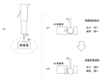
- FIG. 1 is a schematic diagram showing the basic configuration of a medical device 1 according to this embodiment.
- the side of the medical device 1 is shown in a schematic manner when the longitudinal direction of the medical device 1 (the left-right direction on the paper) is the direction from the back side to the front side of the medical device 1.
- the exterior parts of the movable housing 10 and the fixed housing 20 are shown transparently in order to show the components of these housings.
- the longitudinal direction of the medical device 1 (the left-right direction on the paper) is referred to as the cutting direction.
- the medical device 1 is realized as a medical drill equipped with a drill bit 23 for opening a hole in biological tissue.
- the information processing unit 30 calculates various parameters based on information indicating the state of the treatment, that is, information regarding the position detected during the treatment, rather than information indicating the state of the rotational drive of the motor, such as a current value. The information processing unit 30 then appropriately determines whether the treatment has reached a predetermined state based on the various parameters. In other words, the medical device 1 makes it possible to more appropriately grasp the status of treatment during medical procedures. This is an outline of the present embodiment.
- the movable housing 10 includes a master side unit 11 (including a master side driver 111, a master side actuator 112, and a master side position sensor 113), a switch 12, and a switch lever 13. Furthermore, the fixed housing 20 includes a slave side unit 21 (including a slave side driver 211, a slave side actuator 212, and a slave side position sensor 213), a drill bit rotation motor 22, and a drill bit 23.
- a master side unit 11 including a master side driver 111, a master side actuator 112, and a master side position sensor 113
- the fixed housing 20 includes a slave side unit 21 (including a slave side driver 211, a slave side actuator 212, and a slave side position sensor 213), a drill bit rotation motor 22, and a drill bit 23.
- the master side unit 11 and the slave side unit 21 drive two linear motors, the master side actuator 112 and the slave side actuator 212, and one rotary motor, the drill bit rotation motor 22.
- the slave-side actuator 212 is physically connected to the fixed housing 20 and the drill blade rotation motor 22 (and the drill blade 23 physically connected thereto), and is a linear motor that imparts a driving force for linear movement in the cutting direction to the drill blade rotation motor 22 and the drill blade 23.
- the slave-side actuator 212 is realized by, for example, a linear voice coil motor.
- the drill blade rotation motor 22 and the drill blade 23 are supported by the fixed housing 20 in a state in which they can move linearly in the cutting direction.
- the tip of the drill blade 23 protrudes from or is shielded from the fixed housing 20 depending on the propulsion direction of the propulsive force applied by the slave-side actuator 212.
- the drill blade rotation motor 22 is a rotation motor that is physically connected to the drill blade 23 and the slave-side actuator 212, and that applies a rotational force to the drill blade 23, which is a treatment mechanism, for rotating the drill shaft as a rotation axis. Based on the applied rotational force, the drill blade 23 rotates with the cutting direction as the rotation axis, thereby coming into contact with the treatment site 40 and performing cutting.
- the drill bit rotation motor 22 applies a rotational force of a constant strength, but this is not limited to the above, and the operator may adjust the strength of the rotational force applied by the drill bit rotation motor 22 by operating a foot pedal or the like (not shown).
- the operator When actually performing treatment, the operator first holds the switch lever 13 while fixing the fixed housing 20 near the treatment target area 40. This presses the switch 12, and the master actuator 112, slave actuator 212, and drill bit rotation motor 22 start to operate.
- the operator also performs an operation to move the movable housing 10, which is the operating mechanism, linearly toward the treatment target area 40. Then, through bilateral control, haptic force is transmitted between the master actuator 112 and the slave actuator 212, and the drill blade rotation motor 22 and the drill blade 23 move linearly toward the treatment target area 40. As a result, the rotating drill blade 23 is pressed against the treatment target area 40, and a treatment is performed to cut the vertebrae, which is the treatment target area 40.
- the medical device 1 achieves bilateral control, transmitting haptic sensations between the movable housing 10, which is the operating mechanism, and the fixed housing 20, which is the treatment mechanism. Therefore, the operator can use the medical device 1 in the same way as a general medical drill equipped with only one rotary motor, without being aware of the presence of the two linear motors.
- the information processing unit 30 calculates various parameters based on information indicating the state of the treatment, that is, information regarding the position detected during the treatment, rather than information indicating the state of the rotational drive of the motor, such as a current value. Then, the information processing unit 30 more appropriately grasps whether the treatment has reached a predetermined state based on the various parameters. In other words, the medical device 1 makes it possible to more appropriately grasp the status of treatment during medical procedures.
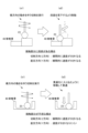
- Fig. 2 is a block diagram showing the hardware configuration of the master unit 11 and the slave unit 21.
- the master-side unit 11 includes a master-side actuator 112 for driving the operation mechanism 50, a master-side driver 111 for driving the master-side actuator 112, and a master-side position sensor 113 for detecting the position of a movable part of the operation mechanism 50 moved by the driving of the master-side actuator 112.
- the master-side unit 11 is also connected to the operation mechanism 50 to be driven.
- the movable housing 10 corresponds to the operation mechanism 50.
- the information processing unit 30 outputs control commands to the master side driver 111 and the slave side driver 211 based on the positions of each mechanism detected by the master side position sensor 113 and the slave side position sensor 213, thereby realizing bilateral control that transmits force haptics between the operation mechanism 50 of the master side unit 11, which is the master device, and the treatment mechanism 60 of the slave side unit 21, which is the slave device.
- a specific algorithm for realizing control for transmitting this haptic sensation (bilateral control) will be described later with reference to FIG.
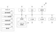
- FIG. 3 is a block diagram showing an example of the hardware configuration and functional blocks of the information processing unit 30.
- the information processing unit 30 includes a processor 31, a ROM (Read Only Memory) 32, a RAM (Random Access Memory) 33, a communication unit 34, a storage unit 35, an input unit 36, an output unit 37, and a drive 38. These units send and receive data to and from each other via signal lines.
- ROM Read Only Memory
- RAM Random Access Memory
- the processor 31 executes various processes according to a program recorded in the ROM 32 or a program loaded from the storage unit 35 to the RAM 33.
- the RAM 33 also stores data and the like necessary for the processor 31 to execute various processes.
- the communication unit 34 controls communication so that the processor 31 can communicate with the master unit 11, the slave unit 21, and other devices.
- the storage unit 35 is composed of semiconductor memory such as DRAM (Dynamic Random Access Memory) and stores various data.
- the input unit 36 is composed of input devices such as various buttons provided in the medical device 1, or external input devices such as a mouse and a keyboard, and inputs various information according to instructions and operations of the operator.
- the output unit 37 is composed of a display, a speaker, etc., and outputs images, voices, warning sounds, etc.
- a removable medium (not shown), such as a magnetic disk, an optical disk, a magneto-optical disk, or a semiconductor memory, is appropriately loaded into the drive 38.
- a program read from the removable medium by the drive 38 is installed in the storage unit 35 as necessary. Note that the above hardware configuration is the basic configuration of the information processing unit 30, and it is possible to have a configuration without some of the hardware, to have additional hardware, or to change the implementation form of the hardware.
- the functional force/speed allocation conversion block FT is a block that defines the conversion of control energy into the speed (position) and force ranges that are set according to the functions of the controlled system CS. Specifically, the functional force/speed allocation conversion block FT defines a coordinate conversion that takes as input the reference value (reference value) of the function of the controlled system CS and the current position (or current angle) of the movable parts of each mechanism that are moved by the drive of the master actuator 112 and the slave actuator 212.
- This coordinate conversion generally converts an input vector whose elements are the reference value and the current position (current angle) into an output vector consisting of a position (angle) for calculating a control target value for position (angle), and also converts an input vector whose elements are the reference value and the current force into an output vector consisting of a force for calculating a control target value for force.
- the coordinate transformation in the functional force/speed allocation transformation block FT By setting the coordinate transformation in the functional force/speed allocation transformation block FT to a content that represents the force-haptic transmission function, it is possible to realize the force-haptic transmission function between the master unit 11 and the slave unit 21, and to reproduce the force-haptic transmission operation in the slave unit 21 without using the master unit 11.
- coefficients in the elements of the transformation matrix in the coordinate transformation in the functional force/speed allocation transformation block FT it is possible to perform scaling of the position (angle) or force.
- the individual variables (variables in real space) of the movable parts of each mechanism moved by the master actuator 112 or the slave actuator 212 are "converted" into a group of variables (variables in space after coordinate transformation) of the entire system that expresses the force haptic transmission function, and control energy is assigned to the control energy of position (angle) and the control energy of force.
- the coordinate transformation set in the functional force/speed allocation conversion block FT converts the coordinates (oblique coordinates) of real space in which position (angle) and force are related to each other into coordinates (orthogonal coordinates) of virtual space in which position (angle) and force are independent of each other.
- the ideal force source block FC is a block that performs calculations in the force domain according to the coordinate transformation defined by the functional force-speed allocation transformation block FT.
- a target value for force is set when performing calculations based on the coordinate transformation defined by the functional force-speed allocation transformation block FT.
- This target value is set as a fixed value or a variable value depending on the function to be realized. For example, when a function similar to the function indicated by the reference value is to be realized, zero can be set as the target value, and when scaling is performed, a value obtained by enlarging or reducing the information indicating the function indicated by the reference value can be set.
- the ideal force source block FC can set an upper limit value for the force energy determined by calculations in the force domain.
- the contact force of the treatment mechanism 60 driven by the slave side unit 21 when it comes into contact with the treatment target area 40 is limited, and the treatment mechanism 60 can be prevented from being pressed excessively hard against the treatment target area 40.
- the ideal speed (position) source block PC is a block that performs calculations in the position (angle) domain according to the coordinate transformation defined by the functional force-speed allocation transformation block FT.
- a target value for the position (angle) when performing calculations based on the coordinate transformation defined by the functional force-speed allocation transformation block FT is set.
- This target value is set as a fixed value or a variable value depending on the function to be realized. For example, when realizing a function similar to the function indicated by the reference value, zero can be set as the target value, and when scaling is performed, a value obtained by enlarging or reducing the information indicating the function to be reproduced can be set.
- the inverse transformation block IFT is a block that inversely transforms values in the position (angle) and force domains into values in the input domain to the controlled system CS (e.g., voltage values or current values, etc.) (i.e., determines command values in real space).
- the information processing unit 30 receives as input time-series position (angle) detection values detected by the master-side position sensor 113 and the slave-side position sensor 213. These time-series position (angle) detection values represent the operations of the master-side actuator 112 and the slave-side actuator 212, and the information processing unit 30 applies coordinate transformation for transmitting haptics to the input positions (angles) and forces derived from these positions (angles).
- the parameter acquisition unit 312 acquires information about the position used in the control of the operation by the operation control unit 311, and calculates a control parameter (i.e., a control parameter related to the force and touch) based on this information about the position.
- a control parameter i.e., a control parameter related to the force and touch
- the parameter acquisition unit 312 acquires information regarding the positions of the movable parts of the operation mechanism 50 and the treatment mechanism 60 detected by the master side position sensor 113 and the slave side position sensor 213 .
- the force of the actuator can be calculated as the product of the mass and the acceleration, and the velocity (position) of the actuator can be calculated by integrating the acceleration. Therefore, for example, the parameter acquisition unit 312 calculates a value indicating the position and a value indicating the force by performing calculations such as integration in real time based on the position of each actuator detected by each position sensor and information corresponding to the coordinate conversion result of the operation control unit 311, and sets these as control parameters. Furthermore, the parameter acquisition unit 312 stores the calculated control parameters in the parameter storage unit 351 .
- the longitudinal direction of the operating table 75 is defined as the Y direction
- the direction perpendicular to the Y direction on the horizontal plane is defined as the X direction
- the direction perpendicular to both the X direction and the Y direction is defined as the Z direction.
- Support parts 71 for supporting members such as rail parts 72 are arranged around the operating table 75. Furthermore, the rail parts 72 support the guides 73 in a state in which they can slide and move linearly in the horizontal direction (here, the Y direction).
- step S20 the situation determination unit 314 determines whether or not it has detected that the treatment has reached a predetermined situation (here, penetration of the vertebrae) through a determination involving the above-mentioned threshold change process and step movement detection process. If it has detected that the treatment has reached the predetermined situation, it is determined as Yes in step S20, and the process proceeds to step S21. On the other hand, if it has not detected that the treatment has reached the predetermined situation, it is determined as No in step S20, and the process proceeds to step S22.
- step S21 the operation control unit 311 switches the control of the operation so as to suppress the treatment performed by the treatment mechanism 60.
- the operation control unit 311 may be realized not by a general-purpose arithmetic processing device, but by a dedicated processing circuit such as an ASIC (Application Specific Integrated Circuit) or an FPGA (Field-Programmable Gate Array).
- ASIC Application Specific Integrated Circuit
- FPGA Field-Programmable Gate Array
- the state specifying unit 313 calculates, as a state parameter, a state parameter indicating the moving speed of the treatment mechanism 60 in a direction different from the direction in which the slave side actuator 212 operates the treatment mechanism 60.
- the status determination unit 314 detects that the treatment mechanism 60 is moving in a different direction at a predetermined speed or faster based on the status parameters indicating the movement status of the treatment mechanism 60, it does not detect that the treatment status has reached a predetermined status, regardless of the control parameters. This makes it possible to prevent erroneous detection of fluctuations in the control parameters when the operator makes large, unintentional movements in different directions.
- the operation control unit 311 suppresses the treatment performed by the treatment mechanism 60 when the situation determination unit 314 determines that the treatment by the treatment mechanism 60 has reached a predetermined situation. This makes it possible to carry out control to suppress treatment when it is determined that a situation has arisen in which treatment should be suppressed.
- the function of executing the series of processes according to the above-mentioned embodiment can be realized by hardware, software, or a combination of these. In other words, it is sufficient that the function of executing the series of processes described above is realized in any one of the medical devices 1, and there is no particular limitation on how this function is realized.
- the recording medium provided to the user in a state where it is preinstalled in the computer main body is, for example, the ROM 32 in FIG. 3 in which the program is recorded, or an SSD (Solid State Drive) or hard disk that realizes the memory unit 35 in FIG. 3, etc.
Landscapes
- Health & Medical Sciences (AREA)
- Surgery (AREA)
- Life Sciences & Earth Sciences (AREA)
- Biomedical Technology (AREA)
- Medical Informatics (AREA)
- Orthopedic Medicine & Surgery (AREA)
- Oral & Maxillofacial Surgery (AREA)
- Engineering & Computer Science (AREA)
- Dentistry (AREA)
- Heart & Thoracic Surgery (AREA)
- Nuclear Medicine, Radiotherapy & Molecular Imaging (AREA)
- Molecular Biology (AREA)
- Animal Behavior & Ethology (AREA)
- General Health & Medical Sciences (AREA)
- Public Health (AREA)
- Veterinary Medicine (AREA)
- Surgical Instruments (AREA)
Priority Applications (1)
| Application Number | Priority Date | Filing Date | Title |
|---|---|---|---|
| JP2025524892A JPWO2024248113A1 (https=) | 2023-05-30 | 2024-05-30 |
Applications Claiming Priority (2)
| Application Number | Priority Date | Filing Date | Title |
|---|---|---|---|
| JP2023089291 | 2023-05-30 | ||
| JP2023-089291 | 2023-05-30 |
Publications (1)
| Publication Number | Publication Date |
|---|---|
| WO2024248113A1 true WO2024248113A1 (ja) | 2024-12-05 |
Family
ID=93658180
Family Applications (1)
| Application Number | Title | Priority Date | Filing Date |
|---|---|---|---|
| PCT/JP2024/019964 Ceased WO2024248113A1 (ja) | 2023-05-30 | 2024-05-30 | 医療機器、及び医療用プログラム |
Country Status (2)
| Country | Link |
|---|---|
| JP (1) | JPWO2024248113A1 (https=) |
| WO (1) | WO2024248113A1 (https=) |
Citations (3)
| Publication number | Priority date | Publication date | Assignee | Title |
|---|---|---|---|---|
| US5339799A (en) * | 1991-04-23 | 1994-08-23 | Olympus Optical Co., Ltd. | Medical system for reproducing a state of contact of the treatment section in the operation unit |
| WO2020008807A1 (ja) * | 2018-07-06 | 2020-01-09 | 地方独立行政法人神奈川県立産業技術総合研究所 | 医療用把持装置 |
| JP2021159364A (ja) * | 2020-03-31 | 2021-10-11 | 地方独立行政法人神奈川県立産業技術総合研究所 | 医療機器、及び医療用プログラム |
-
2024
- 2024-05-30 JP JP2025524892A patent/JPWO2024248113A1/ja active Pending
- 2024-05-30 WO PCT/JP2024/019964 patent/WO2024248113A1/ja not_active Ceased
Patent Citations (3)
| Publication number | Priority date | Publication date | Assignee | Title |
|---|---|---|---|---|
| US5339799A (en) * | 1991-04-23 | 1994-08-23 | Olympus Optical Co., Ltd. | Medical system for reproducing a state of contact of the treatment section in the operation unit |
| WO2020008807A1 (ja) * | 2018-07-06 | 2020-01-09 | 地方独立行政法人神奈川県立産業技術総合研究所 | 医療用把持装置 |
| JP2021159364A (ja) * | 2020-03-31 | 2021-10-11 | 地方独立行政法人神奈川県立産業技術総合研究所 | 医療機器、及び医療用プログラム |
Also Published As
| Publication number | Publication date |
|---|---|
| JPWO2024248113A1 (https=) | 2024-12-05 |
Similar Documents
| Publication | Publication Date | Title |
|---|---|---|
| US20260033900A1 (en) | Robotic Surgical Systems And Methods For Mitigating Tool Skiving | |
| KR102149008B1 (ko) | 수술용 로봇의 충돌을 완화시키는 방법 및 시스템 | |
| Dai et al. | Milling state identification based on vibration sense of a robotic surgical system | |
| Schostek et al. | Review on aspects of artificial tactile feedback in laparoscopic surgery | |
| Tholey et al. | Force feedback plays a significant role in minimally invasive surgery: results and analysis | |
| Tavakoli et al. | High-fidelity bilateral teleoperation systems and the effect of multimodal haptics | |
| Louredo et al. | DRIBON: A mechatronic bone drilling tool | |
| Diaz et al. | Bone drilling methodology and tool based on position measurements | |
| EP2381861B1 (en) | Palpation algorithms for computer-augmented hand tools | |
| EP4070752A1 (en) | Computer-assisted surgery system | |
| Sherman et al. | Comparison of teleoperator control architectures for palpation task | |
| JP7679178B2 (ja) | 医療用ドリル、及び医療用プログラム | |
| CN114886569A (zh) | 触觉致动器的均匀缩放 | |
| JP7722362B2 (ja) | コンピュータ支援手術システム、手術用制御装置、手術用制御方法、プログラムおよび非一時的記憶媒体 | |
| WO2024248113A1 (ja) | 医療機器、及び医療用プログラム | |
| WO2022214697A1 (en) | Computer-assisted surgery system | |
| Accini et al. | Using an admittance algorithm for bone drilling procedures | |
| Tholey et al. | Measuring grasping and cutting forces for reality-based haptic modeling | |
| Ha-Van et al. | Design and characterization of an actuated drill mockup for orthopedic surgical training | |
| Wagner et al. | Force feedback in a three-dimensional ultrasound-guided surgical task | |
| Yu et al. | Frequency-based analysis of the relationship between cutting force and CT number for an implant-surgery-teaching robot | |
| CN115802969B (zh) | 用于脉管内腔中进行激光导管处置的系统和方法 | |
| JP2022009382A (ja) | ジョイント構造物 | |
| WO2023074333A1 (ja) | 情報提示システム、情報提示装置、情報提示方法及びプログラム | |
| JP2014158577A (ja) | 内視鏡システム |
Legal Events
| Date | Code | Title | Description |
|---|---|---|---|
| 121 | Ep: the epo has been informed by wipo that ep was designated in this application |
Ref document number: 24815593 Country of ref document: EP Kind code of ref document: A1 |
|
| ENP | Entry into the national phase |
Ref document number: 2025524892 Country of ref document: JP Kind code of ref document: A |
|
| NENP | Non-entry into the national phase |
Ref country code: DE |