WO2024247781A1 - 円筒形電池 - Google Patents
円筒形電池 Download PDFInfo
- Publication number
- WO2024247781A1 WO2024247781A1 PCT/JP2024/018460 JP2024018460W WO2024247781A1 WO 2024247781 A1 WO2024247781 A1 WO 2024247781A1 JP 2024018460 W JP2024018460 W JP 2024018460W WO 2024247781 A1 WO2024247781 A1 WO 2024247781A1
- Authority
- WO
- WIPO (PCT)
- Prior art keywords
- negative electrode
- core
- mixture layer
- exposed portion
- winding
- Prior art date
- Legal status (The legal status is an assumption and is not a legal conclusion. Google has not performed a legal analysis and makes no representation as to the accuracy of the status listed.)
- Ceased
Links
Images


Classifications
-
- Y—GENERAL TAGGING OF NEW TECHNOLOGICAL DEVELOPMENTS; GENERAL TAGGING OF CROSS-SECTIONAL TECHNOLOGIES SPANNING OVER SEVERAL SECTIONS OF THE IPC; TECHNICAL SUBJECTS COVERED BY FORMER USPC CROSS-REFERENCE ART COLLECTIONS [XRACs] AND DIGESTS
- Y02—TECHNOLOGIES OR APPLICATIONS FOR MITIGATION OR ADAPTATION AGAINST CLIMATE CHANGE
- Y02E—REDUCTION OF GREENHOUSE GAS [GHG] EMISSIONS, RELATED TO ENERGY GENERATION, TRANSMISSION OR DISTRIBUTION
- Y02E60/00—Enabling technologies; Technologies with a potential or indirect contribution to GHG emissions mitigation
- Y02E60/10—Energy storage using batteries
-
- Y—GENERAL TAGGING OF NEW TECHNOLOGICAL DEVELOPMENTS; GENERAL TAGGING OF CROSS-SECTIONAL TECHNOLOGIES SPANNING OVER SEVERAL SECTIONS OF THE IPC; TECHNICAL SUBJECTS COVERED BY FORMER USPC CROSS-REFERENCE ART COLLECTIONS [XRACs] AND DIGESTS
- Y02—TECHNOLOGIES OR APPLICATIONS FOR MITIGATION OR ADAPTATION AGAINST CLIMATE CHANGE
- Y02P—CLIMATE CHANGE MITIGATION TECHNOLOGIES IN THE PRODUCTION OR PROCESSING OF GOODS
- Y02P70/00—Climate change mitigation technologies in the production process for final industrial or consumer products
- Y02P70/50—Manufacturing or production processes characterised by the final manufactured product
Definitions
- This disclosure relates to cylindrical batteries.
- Cylindrical batteries are equipped with a wound electrode body in which a positive electrode and a negative electrode are wound in a spiral shape with a separator between them.
- Patent Document 1 discloses a cylindrical battery equipped with a wound electrode body having a negative electrode mixture layer formed on at least one surface of a negative electrode core at the winding start side of the electrode body, and a non-facing portion that is wound for a predetermined length or more without facing the positive electrode.
- an exposed portion of the core extends further toward the winding start side from the winding start end of the negative electrode mixture layer, and a negative electrode tab is joined to one surface of the exposed portion of the core.
- the negative electrode mixture layer may face the outer periphery of the negative electrode tab via the separator when the electrode body is wound.
- the difference in thickness between the part where the negative electrode tab is joined and the other parts of the exposed core portion at the winding start end of the negative electrode causes the roundness of the electrode body to deteriorate. This deterioration in roundness may cause plate deformation, in which at least one of the positive electrode and the negative electrode is locally deformed, when charge/discharge cycles are repeated.
- the cylindrical battery according to the present disclosure is a cylindrical battery comprising an electrode body in which a positive electrode and a negative electrode including an inner circumferential mixture layer and an outer circumferential mixture layer formed on both sides of a core are wound via a separator, and the negative electrode has a negative electrode tab joined to one side of the core at the end on the side where the winding starts, and an exposed portion in which the core is exposed is provided in a range of the inner circumferential surface of the negative electrode that includes a negative electrode tab opposing portion that faces the outer circumferential side of the portion where the negative electrode tab overlaps with the core via the separator, and an inner circumferential mixture layer is provided on both sides of the exposed portion in the winding direction.
- the cylindrical battery disclosed herein can prevent the negative electrode tab from deteriorating the circularity of the electrode body, thereby preventing plate deformation.
- FIG. 2 is an axial cross-sectional view of a cylindrical battery according to an embodiment of the present invention.
- 2 is a schematic diagram of a portion of a radial cross section of an electrode body according to an embodiment of the present invention.
- FIG. FIG. 3 is an enlarged view of the vicinity of the winding shaft of FIG. 2 .
- FIG. 2 is a perspective view of an example of an embodiment in which a portion of a negative electrode in the longitudinal direction, including the winding start end, is extended linearly.
- 5 is a view of the winding start end of the negative electrode in FIG. 4 as viewed from the inner periphery side.
- 5 is a view of the winding start end portion of the negative electrode in FIG. 4 as viewed from one side in the width direction of the negative electrode.
- This is a cross-sectional view taken along line AA in FIG. 6.
- cylindrical battery according to the present disclosure is not limited to the embodiment described below.
- FIG. 1 is a cross-sectional view of a cylindrical battery 10 according to an embodiment.
- the cylindrical battery 10 has a positive electrode 11, a negative electrode 12, and a separator 13, and is provided with an electrode assembly 14 in which the positive electrode 11 and the negative electrode 12 are wound with the separator 13 interposed therebetween.
- the cylindrical battery 10 also has a cylindrical outer can 16 with a bottom that houses the electrode assembly 14, and a sealing body 17 that closes the opening of the outer can 16.
- the outer can 16 houses an electrolyte together with the electrode assembly 14.
- the outer can 16 has a grooved portion 22 formed in its side wall, and the sealing body 17 is supported by the grooved portion 22 to close the opening of the outer can 16.
- the sealing body 17 side of the cylindrical battery 10 is referred to as the top
- the bottom side of the outer can 16 is referred to as the bottom.
- the negative electrode 12 has a negative electrode mixture layer formed on at least one surface of the negative electrode core 40 at the start of winding of the electrode body 14, and has a non-facing portion 43 (see Figure 2) that is wound 0.5 turns or more without facing the positive electrode 11.
- the non-facing portion 43 ensures a winding core structure of the electrode body 14 with excellent shape stability.
- a cavity is formed on the inside of the winding core along the axial direction.
- the cavity in the winding core functions as an exhaust path that guides gas generated in the event of an abnormality in the battery toward the safety valve.
- the electrolyte may be an aqueous electrolyte, but in this embodiment, a non-aqueous electrolyte is used.
- the non-aqueous electrolyte has lithium ion conductivity.
- the non-aqueous electrolyte may be a liquid electrolyte (electrolytic solution) or a solid electrolyte.
- the cylindrical battery 10 is, for example, a non-aqueous electrolyte secondary battery, and is preferably a lithium ion battery.
- the liquid electrolyte includes a non-aqueous solvent and an electrolyte salt dissolved in the non-aqueous solvent.
- a non-aqueous solvent for example, esters, ethers, nitriles, amides, and mixed solvents of two or more of these are used as the non-aqueous solvent.
- the non-aqueous solvent include ethylene carbonate (EC), ethyl methyl carbonate (EMC), dimethyl carbonate (DMC), diethyl carbonate (DEC), and mixed solvents of these.
- the non-aqueous solvent may contain a halogen-substituted product (e.g., fluoroethylene carbonate, etc.) in which at least a part of the hydrogen of these solvents is replaced with a halogen atom such as fluorine.
- a halogen-substituted product e.g., fluoroethylene carbonate, etc.
- a lithium salt such as LiPF6 is used as the electrolyte salt.
- the solid electrolyte for example, a solid or gel-like polymer electrolyte, an inorganic solid electrolyte, etc. can be used.
- the inorganic solid electrolyte a material known in all-solid-state lithium ion secondary batteries, etc. (for example, an oxide-based solid electrolyte, a sulfide-based solid electrolyte, a halogen-based solid electrolyte, etc.) can be used.
- the polymer electrolyte includes, for example, a lithium salt and a matrix polymer, or a non-aqueous solvent, a lithium salt, and a matrix polymer.
- the matrix polymer for example, a polymer material that absorbs a non-aqueous solvent and gels is used.
- the polymer material for example, a fluororesin, an acrylic resin, a polyether resin, etc. can be used.
- the electrode body 14 has a wound structure in which the positive electrode 11 and the negative electrode 12 are wound in a spiral shape with the separator 13 interposed therebetween.
- the positive electrode 11, the negative electrode 12, and the separator 13 are all long strip-shaped bodies, and are wound in a spiral shape so that they are alternately stacked in the radial direction of the electrode body 14.
- the negative electrode 12 is formed with dimensions slightly larger than the positive electrode 11 to prevent lithium precipitation. In other words, the negative electrode 12 is formed to be longer in the length direction and width direction than the positive electrode 11.
- the separator 13 is formed with dimensions at least slightly larger than the positive electrode 11, and for example, two separators 13 are arranged to sandwich the positive electrode 11.
- a positive electrode tab 20 and a negative electrode tab 21 are connected to the electrode body 14.
- the positive electrode tab 20 electrically connects the positive electrode 11 and the sealing body 17.
- the positive electrode tab 20 is located in the center of the positive electrode 11 in the longitudinal direction, away from the winding start end and winding end end of the electrode body 14.
- the negative electrode tab 21 is provided at the winding start end 40a, which is one end in the longitudinal direction of the negative electrode 12 located at the winding start side of the negative electrode 12.
- the negative electrode 12 is a portion from the negative electrode starting end 12x, which is the winding start end, to the non-facing portion 43, and has a first core exposed portion 42 (see Figure 2) where no negative electrode mixture layer, described below, is present.
- the negative electrode tab 21 is joined to the first core exposed portion 42 in the negative electrode core 40.
- the positive electrode tab 20 passes through the opening of the upper insulating plate 18 and extends toward the sealing body 17, and is joined to the underside of the sealing body 17, making the sealing body 17 the positive electrode terminal.
- the negative electrode tab 21 passes through a through hole in the annular lower insulating plate 19, is bent toward the hollow part of the electrode body 14, and is connected to the inner surface of the bottom of the outer can 16 by welding or the like, making the outer can 16 the negative electrode terminal.
- the negative electrode 12 is disposed on the outermost surface of the electrode body 14, and a second core exposed portion 44 is provided where the surface of the negative electrode core 40 is exposed.
- the core exposed portion 44 abuts against the inner surface of the exterior can 16.
- the core exposed portion 44 abuts against the inner surface of the exterior can 16, which is the negative electrode terminal, electrically connecting both ends in the length direction of the negative electrode 12 to the exterior can 16, ensuring good current collection.
- the core exposed portion 44 may be provided on a part of the outermost surface of the electrode body 14, but is preferably provided over the entire outermost surface. For example, a portion where no negative electrode mixture layer is present is provided on both sides of the negative electrode core 40 for a length of at least one revolution of the electrode body 14 from the winding end of the negative electrode 12.
- the positive electrode 11 has a positive electrode core 30 and a positive electrode mixture layer 31 formed on at least one surface of the core.
- the positive electrode core 30 can be a foil of a metal, such as aluminum or an aluminum alloy, that is stable in the potential range of the positive electrode 11, or a film with the metal disposed on the surface.
- the positive electrode mixture layer 31 contains a positive electrode active material, a conductive agent such as acetylene black, and a binder such as polyvinylidene fluoride (PVdF), and is preferably formed on both sides of the positive electrode core 30.
- the thickness of the positive electrode mixture layer 31 is, for example, 40 ⁇ m or more and 100 ⁇ m or less.
- the positive electrode active material for example, a lithium transition metal composite oxide containing Ni, Co, Mn, Al, etc. is used.
- the positive electrode tab 20 is preferably directly bonded to the positive electrode core 30 by ultrasonic welding or the like.
- FIG. 2 is a schematic diagram of a portion of a radial cross section of the electrode body 14, and in FIG. 2, the gaps between the negative electrodes 12 at the start of winding are exaggerated.
- the positive electrode core and the positive electrode mixture layer are omitted.
- the negative electrode 12 has a negative electrode core 40, a negative electrode mixture layer 41a formed on the inner peripheral surface of the negative electrode core 40 facing the winding axis O of the core, and a negative electrode mixture layer 41b formed on the outer peripheral surface of the negative electrode core 40 facing the side wall of the outer can 16 of the core.
- the negative electrode mixture layer 41a corresponds to the inner peripheral mixture layer
- the negative electrode mixture layer 41b corresponds to the outer peripheral mixture layer.
- the negative electrode core 40 may be made of a foil of a metal, such as copper or a copper alloy, that is stable in the potential range of the negative electrode 12, or a film with the metal disposed on the surface.
- the negative electrode mixture layers 41a, 41b contain a negative electrode active material and a binder such as styrene-butadiene rubber (SBR).
- SBR styrene-butadiene rubber
- the thickness of the negative electrode mixture layers 41a, 41b is, for example, 40 ⁇ m or more and 100 ⁇ m or less.
- the negative electrode active material may be, for example, graphite or a material containing Si.
- the negative electrode tab 21 is preferably directly bonded to the negative electrode core 40 by ultrasonic welding or the like.
- the negative electrode mixture layers 41a, 41b may be collectively referred to as the negative electrode mixture layer 41.
- the exterior can 16 is a cylindrical metal container with a bottom.
- a gasket 28 is provided between the exterior can 16 and the sealing body 17 to seal the inside of the battery.
- the exterior can 16 has a grooved portion 22 that supports the sealing body 17, formed, for example, by pressing the side portion from the outside.
- the grooved portion 22 is preferably formed in an annular shape along the circumferential direction of the exterior can 16, and supports the sealing body 17 on its upper surface.
- the upper end of the exterior can 16 is bent inward and crimped to the peripheral edge of the sealing body 17.
- the sealing body 17 has a structure in which, in order from the electrode body 14 side, a terminal plate 23, a lower valve body 24, an insulating member 25, an upper valve body 26, and a cap 27 are layered.
- Each member constituting the sealing body 17 has, for example, a disk or ring shape, and each member except for the insulating member 25 is electrically connected to each other.
- the lower valve body 24 and the upper valve body 26 are connected to each other at their respective centers, and the insulating member 25 is interposed between their respective peripheral edges.
- Fig. 3 is an enlarged view of the vicinity of winding axis O in Fig. 2.
- Fig. 4 is a perspective view of a longitudinal part of the negative electrode 12 including the winding start end in a straight line in one embodiment.
- Fig. 5 is a view of the winding start end of the negative electrode 12 in Fig. 4 as seen from the inner circumference side.
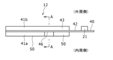
- Fig. 6 is a view of the winding start end of the negative electrode 12 in Fig. 4 as seen from one side in the negative electrode width direction.
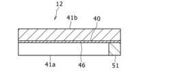
- Fig. 7 is a cross-sectional view taken along line A-A in Fig. 6.
- the negative electrode 12 constituting the electrode body 14 has a negative electrode mixture layer 41 formed on at least one surface of the negative electrode core 40 at the winding start side, and a non-facing portion 43 wound 0.5 turns or more without facing the positive electrode 11 via the separator 13.
- the non-facing portion 43 has the negative electrode mixture layer 41, but does not face the positive electrode 11, so it does not contribute to the charging and discharging of the battery.
- the non-facing portion 43 has high rigidity because it has the negative electrode mixture layer 41, contributes to stabilizing the shape of the winding core portion of the electrode body 14, and ensures an exhaust path for gas generated when an abnormality occurs in the battery. Note that the portion located on the winding end side of the electrode body 14 from the positive electrode start end 11x becomes the facing portion of the positive and negative electrodes where the positive electrode 11 and the negative electrode 12 face each other via the separator 13.
- the positive electrode starting end 11x refers to one end in the length direction of the positive electrode 11 located on the winding start side (winding core side) of the electrode body 14.
- the negative electrode starting end 12x refers to one end in the length direction of the negative electrode 12 located on the winding start side of the electrode body 14.
- the negative electrode starting end 12x is located closer to the winding axis O than the positive electrode starting end 11x.
- the negative electrode mixture layer 41 may be formed on either the inner or outer peripheral surface of the negative electrode core 40, but is preferably formed continuously for 0.5 or more revolutions on both the inner and outer peripheral surfaces of the negative electrode core 40. In this case, the shape stability of the winding core portion is further improved.
- the negative electrode mixture layer 41 is preferably formed on both sides of the negative electrode core 40 from a position facing at least the inner peripheral side of the positive electrode starting end 11x via the separator 13, and may be formed on both sides of the negative electrode core 40 over the entire length of the non-facing portion 43.
- the non-facing portion 43 is preferably formed with a length of, for example, 0.5 or more revolutions and 1.5 or less revolutions, more preferably 0.90 or more revolutions and 1.4 or less revolutions, and particularly preferably 1.0 or more revolutions and 1.3 or less revolutions. In this case, it is easy to ensure a good exhaust path in the winding core portion.
- the negative electrode 12 has a core exposed portion 42 that is a portion from the negative electrode starting end 12x to the non-facing portion 43.
- the core exposed portion 42 is a portion that does not face the positive electrode 11, like the non-facing portion 43, but differs from the non-facing portion 43 in that it does not have a negative electrode mixture layer 41 and is composed only of the negative electrode core 40.
- the negative electrode tab 21 is joined to the portion of the core exposed portion 42 that forms the innermost circumference of the negative electrode 12.
- the length of the core exposed portion 42 is not particularly limited, but from the viewpoint of ensuring the bonding area of the negative electrode tab 21, it is preferable that the length be 0.5 or more circumferences.
- the core exposed portion 42 may be formed with a length of 0.5 or more circumferences and 1.0 or less circumferences.
- the negative electrode tab 21 is, for example, a metal thin plate whose main component is a metal such as nickel, and has a thickness of 50 ⁇ m or more and 100 ⁇ m or less. The negative electrode tab 21 is bonded to the outer peripheral surface of the core exposed portion 42 at the innermost circumference of the negative electrode 12.
- the core exposed portion 42 of the negative electrode core 40 is 1.0 or more revolutions long, and the negative electrode tab 21 is joined to the portion of the core exposed portion 42 that forms the innermost circumference of the negative electrode 12.
- the negative electrode mixture layer 41 may be provided on a part of the innermost circumference of the negative electrode 12.
- the innermost circumference of the negative electrode 12 may be formed by a portion consisting of 0.5 revolutions of the core exposed portion 42 and 0.5 revolutions of the non-facing portion 43 that continues to the end of the winding of the core exposed portion 42.
- the negative electrode 12 has a negative electrode tab facing portion 45 that faces the outer periphery of the portion where the negative electrode tab 21 and the negative electrode core 40 overlap on the inner periphery, via two separators 13.
- a third core exposed portion 46 where the negative electrode core 40 is exposed is provided in an area including the negative electrode tab facing portion 45.
- Negative electrode mixture layers 41a are provided adjacent to the core exposed portion 46 on both sides of the winding direction of the core exposed portion 46.
- a recess is formed in a part of the negative electrode mixture layer 41a on the inner periphery side in the non-facing portion 43, which is recessed in a rectangular cross section so as to extend in the negative electrode width direction ⁇ ( Figure 5), and the negative electrode core 40 is exposed at the bottom of the recess, forming a core exposed portion 46.
- the negative electrode mixture layer 41a is adjacent to the core exposed portion 46 on both sides of the winding direction of the core exposed portion 46.
- the length of the core exposed portion 46 in the negative electrode longitudinal direction ⁇ ( Figure 5) is greater than the width W of the negative electrode tab 21.
- the length of the core exposed portion 46 in the negative electrode width direction ⁇ ( Figure 5) corresponding to the direction of the winding axis O of the electrode body 14 is greater than the length L of the negative electrode width direction ⁇ of the portion of the negative electrode tab 21 that overlaps with the negative electrode core 40.
- the length L of the core exposed portion 46 in the negative electrode width direction may be smaller than the length of the negative electrode 12 in the width direction, and a main thickness portion 51 having the same thickness as the main thickness portion 50 of the negative electrode mixture layer 41a provided on both sides of the winding direction of the core exposed portion 46 may be provided between the core exposed portion 46 and one end of the negative electrode 12 in the width direction.
- the rigidity of the negative electrode 12 can be increased despite the core exposed portion 46 being provided on the negative electrode 12.
- the core exposed portion 46 is preferably provided in at least a part of the negative electrode width direction ⁇ .
- the core exposed portion 46 may be provided over the entire length of the negative electrode 12 in the negative electrode width direction ⁇ .
- the main thickness portion 50 of the negative electrode mixture layer 41a refers to a region having a constant thickness that occupies most of the negative electrode mixture layer 41a.
- a negative electrode mixture layer 41b of the same thickness as the main thickness portion 50 is provided on the portion of the outer peripheral surface of the negative electrode core that overlaps with the core exposed portion 46.
- the core exposed portion 46 preferably has a length of one turn or less in the winding direction of the negative electrode 12. More preferably, the core exposed portion 46 has a length of 0.5 turns or less in the winding direction. For example, the core exposed portion 46 has a length of about 0.25 turns in the winding direction.
- intermittent coating can be performed only on a rectangular portion of a predetermined range that forms the core exposed portion 46 in the negative electrode 12, so that the negative electrode mixture layer 41a is not formed on the inner circumference side partially in the negative electrode width direction.
- the negative electrode tab 21 easily fits into the recess formed by the core exposed portion 46 as shown in FIG. 3. Therefore, regardless of the presence of the negative electrode tab 21, the effect of the difference in thickness between the portion where the negative electrode tab 21 is joined and other portions in the core exposed portion 42 at the start of winding can be reduced. This makes it possible to suppress deterioration of the circularity of the electrode body 14 caused by the negative electrode tab 21, and therefore suppress plate deformation even when charge/discharge cycles are repeated.
- the negative electrode tab 21 is joined to the outer peripheral surface of the core exposed portion 42, but the negative electrode tab 21 may be joined to the inner peripheral surface of the core exposed portion 42.
- the portion of the core exposed portion 42 that overlaps with the negative electrode tab is more likely to fit into the recess formed by the core exposed portion 46. This makes it possible to suppress deterioration of the circularity of the electrode body due to the negative electrode tab 21, and therefore suppress deformation of the electrode plate.
- Configuration 1 A cylindrical battery having an electrode assembly in which a positive electrode, an inner circumferential side mixture layer and an outer circumferential side mixture layer formed on both sides of a core body, and a negative electrode including the inner circumferential side mixture layer and the outer circumferential side mixture layer are wound with a separator interposed therebetween,
- the negative electrode has a negative electrode tab joined to one surface of the core body at a winding start end, an exposed portion in which the core body is exposed is provided in a range including a negative electrode tab opposing portion that faces an outer circumferential side of a portion of an inner circumferential surface of the negative electrode at which the negative electrode tab and the core body overlap with each other via the separator,
- the inner circumferential mixture layer is provided on both sides of the exposed portion in the winding direction.
- Configuration 2 The exposed portion is provided in at least a part of the negative electrode width direction corresponding to the winding axis direction of the electrode body. 2.
- Configuration 3 The exposed portion has a length of one turn or less in the winding direction.
- Configuration 4 The negative electrode includes at least one of the inner circumferential side mixture layer and the outer circumferential side mixture layer at a winding start side of the electrode body, and has a non-facing portion that is wound 0.5 turns or more in a state of not facing the positive electrode via the separator. 4.
Landscapes
- Secondary Cells (AREA)
Priority Applications (1)
| Application Number | Priority Date | Filing Date | Title |
|---|---|---|---|
| JP2025523481A JPWO2024247781A1 (https=) | 2023-05-31 | 2024-05-20 |
Applications Claiming Priority (2)
| Application Number | Priority Date | Filing Date | Title |
|---|---|---|---|
| JP2023089945 | 2023-05-31 | ||
| JP2023-089945 | 2023-05-31 |
Publications (1)
| Publication Number | Publication Date |
|---|---|
| WO2024247781A1 true WO2024247781A1 (ja) | 2024-12-05 |
Family
ID=93657870
Family Applications (1)
| Application Number | Title | Priority Date | Filing Date |
|---|---|---|---|
| PCT/JP2024/018460 Ceased WO2024247781A1 (ja) | 2023-05-31 | 2024-05-20 | 円筒形電池 |
Country Status (2)
| Country | Link |
|---|---|
| JP (1) | JPWO2024247781A1 (https=) |
| WO (1) | WO2024247781A1 (https=) |
Citations (4)
| Publication number | Priority date | Publication date | Assignee | Title |
|---|---|---|---|---|
| JP2009043718A (ja) * | 2007-07-17 | 2009-02-26 | Panasonic Corp | 二次電池および二次電池の製造方法 |
| JP2009059686A (ja) * | 2007-07-20 | 2009-03-19 | Panasonic Corp | 電池用電極板、電池用極板群、リチウム二次電池、電池用電極板の製造方法、及び電池用電極板の製造装置 |
| WO2018116876A1 (ja) * | 2016-12-22 | 2018-06-28 | 三洋電機株式会社 | 円筒形の非水電解質二次電池 |
| WO2020262437A1 (ja) * | 2019-06-28 | 2020-12-30 | 三洋電機株式会社 | 円筒形非水電解質二次電池 |
-
2024
- 2024-05-20 JP JP2025523481A patent/JPWO2024247781A1/ja active Pending
- 2024-05-20 WO PCT/JP2024/018460 patent/WO2024247781A1/ja not_active Ceased
Patent Citations (4)
| Publication number | Priority date | Publication date | Assignee | Title |
|---|---|---|---|---|
| JP2009043718A (ja) * | 2007-07-17 | 2009-02-26 | Panasonic Corp | 二次電池および二次電池の製造方法 |
| JP2009059686A (ja) * | 2007-07-20 | 2009-03-19 | Panasonic Corp | 電池用電極板、電池用極板群、リチウム二次電池、電池用電極板の製造方法、及び電池用電極板の製造装置 |
| WO2018116876A1 (ja) * | 2016-12-22 | 2018-06-28 | 三洋電機株式会社 | 円筒形の非水電解質二次電池 |
| WO2020262437A1 (ja) * | 2019-06-28 | 2020-12-30 | 三洋電機株式会社 | 円筒形非水電解質二次電池 |
Also Published As
| Publication number | Publication date |
|---|---|
| JPWO2024247781A1 (https=) | 2024-12-05 |
Similar Documents
| Publication | Publication Date | Title |
|---|---|---|
| JP7669293B2 (ja) | 密閉電池 | |
| WO2017098690A1 (ja) | 電池 | |
| JP7664220B2 (ja) | 密閉電池 | |
| WO2025028226A1 (ja) | 非水電解質二次電池 | |
| WO2024181071A1 (ja) | 二次電池 | |
| WO2024181051A1 (ja) | 円筒形電池 | |
| WO2024247781A1 (ja) | 円筒形電池 | |
| WO2024247779A1 (ja) | 円筒形電池 | |
| JP2013164982A (ja) | 巻回型電池 | |
| WO2024181038A1 (ja) | 円筒形電池 | |
| WO2024262490A1 (ja) | 円筒形電池及びその製造方法 | |
| WO2026094755A1 (ja) | 円筒形電池 | |
| EP4641824A1 (en) | Cylindrical battery | |
| WO2024224957A1 (ja) | 円筒形電池及びその製造方法 | |
| WO2024143257A1 (ja) | 円筒形電池 | |
| WO2026094792A1 (ja) | 円筒形電池 | |
| WO2024203197A1 (ja) | 円筒形電池 | |
| WO2025183002A1 (ja) | 非水電解質二次電池 | |
| WO2026048533A1 (ja) | 円筒形二次電池 | |
| WO2026048508A1 (ja) | 円筒形電池 | |
| WO2025047154A1 (ja) | 円筒形電池 | |
| WO2024143254A1 (ja) | 円筒形電池 | |
| WO2025229947A1 (ja) | 非水電解質二次電池 | |
| WO2024161967A1 (ja) | 円筒形電池 | |
| WO2024142995A1 (ja) | 円筒形電池 |
Legal Events
| Date | Code | Title | Description |
|---|---|---|---|
| 121 | Ep: the epo has been informed by wipo that ep was designated in this application |
Ref document number: 24815265 Country of ref document: EP Kind code of ref document: A1 |
|
| ENP | Entry into the national phase |
Ref document number: 2025523481 Country of ref document: JP Kind code of ref document: A |
|
| WWE | Wipo information: entry into national phase |
Ref document number: 2025523481 Country of ref document: JP |
|
| NENP | Non-entry into the national phase |
Ref country code: DE |