WO2024247496A1 - 電池 - Google Patents
電池 Download PDFInfo
- Publication number
- WO2024247496A1 WO2024247496A1 PCT/JP2024/014347 JP2024014347W WO2024247496A1 WO 2024247496 A1 WO2024247496 A1 WO 2024247496A1 JP 2024014347 W JP2024014347 W JP 2024014347W WO 2024247496 A1 WO2024247496 A1 WO 2024247496A1
- Authority
- WO
- WIPO (PCT)
- Prior art keywords
- electrode
- battery
- sealing cap
- case
- tabs
- Prior art date
- Legal status (The legal status is an assumption and is not a legal conclusion. Google has not performed a legal analysis and makes no representation as to the accuracy of the status listed.)
- Ceased
Links
Images

Classifications
-
- H—ELECTRICITY
- H01—ELECTRIC ELEMENTS
- H01G—CAPACITORS; CAPACITORS, RECTIFIERS, DETECTORS, SWITCHING DEVICES, LIGHT-SENSITIVE OR TEMPERATURE-SENSITIVE DEVICES OF THE ELECTROLYTIC TYPE
- H01G11/00—Hybrid capacitors, i.e. capacitors having different positive and negative electrodes; Electric double-layer [EDL] capacitors; Processes for the manufacture thereof or of parts thereof
- H01G11/74—Terminals, e.g. extensions of current collectors
-
- H—ELECTRICITY
- H01—ELECTRIC ELEMENTS
- H01G—CAPACITORS; CAPACITORS, RECTIFIERS, DETECTORS, SWITCHING DEVICES, LIGHT-SENSITIVE OR TEMPERATURE-SENSITIVE DEVICES OF THE ELECTROLYTIC TYPE
- H01G11/00—Hybrid capacitors, i.e. capacitors having different positive and negative electrodes; Electric double-layer [EDL] capacitors; Processes for the manufacture thereof or of parts thereof
- H01G11/78—Cases; Housings; Encapsulations; Mountings
- H01G11/80—Gaskets; Sealings
-
- H—ELECTRICITY
- H01—ELECTRIC ELEMENTS
- H01G—CAPACITORS; CAPACITORS, RECTIFIERS, DETECTORS, SWITCHING DEVICES, LIGHT-SENSITIVE OR TEMPERATURE-SENSITIVE DEVICES OF THE ELECTROLYTIC TYPE
- H01G11/00—Hybrid capacitors, i.e. capacitors having different positive and negative electrodes; Electric double-layer [EDL] capacitors; Processes for the manufacture thereof or of parts thereof
- H01G11/78—Cases; Housings; Encapsulations; Mountings
- H01G11/82—Fixing or assembling a capacitive element in a housing, e.g. mounting electrodes, current collectors or terminals in containers or encapsulations
-
- H—ELECTRICITY
- H01—ELECTRIC ELEMENTS
- H01M—PROCESSES OR MEANS, e.g. BATTERIES, FOR THE DIRECT CONVERSION OF CHEMICAL ENERGY INTO ELECTRICAL ENERGY
- H01M50/00—Constructional details or processes of manufacture of the non-active parts of electrochemical cells other than fuel cells, e.g. hybrid cells
- H01M50/10—Primary casings; Jackets or wrappings
- H01M50/102—Primary casings; Jackets or wrappings characterised by their shape or physical structure
- H01M50/107—Primary casings; Jackets or wrappings characterised by their shape or physical structure having curved cross-section, e.g. round or elliptic
-
- H—ELECTRICITY
- H01—ELECTRIC ELEMENTS
- H01M—PROCESSES OR MEANS, e.g. BATTERIES, FOR THE DIRECT CONVERSION OF CHEMICAL ENERGY INTO ELECTRICAL ENERGY
- H01M50/00—Constructional details or processes of manufacture of the non-active parts of electrochemical cells other than fuel cells, e.g. hybrid cells
- H01M50/10—Primary casings; Jackets or wrappings
- H01M50/147—Lids or covers
- H01M50/148—Lids or covers characterised by their shape
- H01M50/152—Lids or covers characterised by their shape for cells having curved cross-section, e.g. round or elliptic
-
- H—ELECTRICITY
- H01—ELECTRIC ELEMENTS
- H01M—PROCESSES OR MEANS, e.g. BATTERIES, FOR THE DIRECT CONVERSION OF CHEMICAL ENERGY INTO ELECTRICAL ENERGY
- H01M50/00—Constructional details or processes of manufacture of the non-active parts of electrochemical cells other than fuel cells, e.g. hybrid cells
- H01M50/50—Current conducting connections for cells or batteries
- H01M50/531—Electrode connections inside a battery casing
- H01M50/536—Electrode connections inside a battery casing characterised by the method of fixing the leads to the electrodes, e.g. by welding
-
- H—ELECTRICITY
- H01—ELECTRIC ELEMENTS
- H01M—PROCESSES OR MEANS, e.g. BATTERIES, FOR THE DIRECT CONVERSION OF CHEMICAL ENERGY INTO ELECTRICAL ENERGY
- H01M50/00—Constructional details or processes of manufacture of the non-active parts of electrochemical cells other than fuel cells, e.g. hybrid cells
- H01M50/50—Current conducting connections for cells or batteries
- H01M50/531—Electrode connections inside a battery casing
- H01M50/538—Connection of several leads or tabs of wound or folded electrode stacks
-
- Y—GENERAL TAGGING OF NEW TECHNOLOGICAL DEVELOPMENTS; GENERAL TAGGING OF CROSS-SECTIONAL TECHNOLOGIES SPANNING OVER SEVERAL SECTIONS OF THE IPC; TECHNICAL SUBJECTS COVERED BY FORMER USPC CROSS-REFERENCE ART COLLECTIONS [XRACs] AND DIGESTS
- Y02—TECHNOLOGIES OR APPLICATIONS FOR MITIGATION OR ADAPTATION AGAINST CLIMATE CHANGE
- Y02E—REDUCTION OF GREENHOUSE GAS [GHG] EMISSIONS, RELATED TO ENERGY GENERATION, TRANSMISSION OR DISTRIBUTION
- Y02E60/00—Enabling technologies; Technologies with a potential or indirect contribution to GHG emissions mitigation
- Y02E60/10—Energy storage using batteries
Definitions
- This disclosure relates to batteries.
- batteries that have a structure in which one electrode of an electrode group is connected to a sealing body by multiple tabs (for example, Patent Document 1).
- the battery in Patent Document 1 includes a bottomed cylindrical case with an opening at one end, an electrode group that is housed in the case and has a positive electrode and a negative electrode, and a sealing body that seals the opening of the case, and the sealing body has a current collector plate that is connected to the positive electrode via multiple positive electrode tabs, and a cap that is joined to the current collector plate.
- the battery of Patent Document 1 has a sealing body that has two components, a current collector plate and a cap, and therefore during manufacturing it is necessary to join multiple positive electrode tabs to the current collector plate, as well as to join the current collector plate to the cap. In other words, a relatively large number of steps are required to manufacture the battery of Patent Document 1. In this situation, one of the objectives of the present disclosure is to reduce the number of steps required during manufacturing.
- the battery includes a bottomed cylindrical case having an opening at one end, an electrode group housed in the case and having a first electrode and a second electrode, a sealing cap that seals the opening, and a plurality of first tabs that are each electrically connected to the first electrodes and are each welded to the sealing cap.
- This disclosure makes it possible to reduce the amount of work required during manufacturing.
- FIG. 1 is a cross-sectional view illustrating a schematic example of a battery according to the present disclosure.
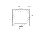
- FIG. 4 is a bottom view illustrating a convex portion according to an exemplary embodiment.
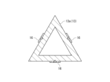
- FIG. 11 is a bottom view showing a schematic view of a convex portion according to a modified example.
- the battery according to the present disclosure may be a primary battery such as a lithium primary battery, or a secondary battery such as an alkaline storage battery (nickel-metal hydride battery, nickel-cadmium battery, etc.), a lithium-ion secondary battery, or a lithium metal secondary battery.
- the category of battery also includes an electricity storage device (e.g., lithium-ion capacitor, electric double layer capacitor) in which at least one of the positive and negative electrodes is a polarizable electrode that exhibits capacity through a non-Faradic reaction.
- the battery according to the present disclosure includes a case, an electrode group, a sealing cap, and a plurality of first tabs.
- the case is formed into a bottomed tubular shape with an opening at one end.
- the case may be made of metal (e.g., aluminum or an aluminum alloy).
- the outer shape of the case may be, for example, a bottomed cylindrical shape or a bottomed rectangular tubular shape.
- the electrode group is housed in a case.
- the electrode group has a first electrode and a second electrode.
- Each of the first electrode and the second electrode may be configured in a strip shape (or a long sheet shape).
- the electrode group may be configured, for example, by winding the first electrode and the second electrode with a strip-shaped separator interposed therebetween.
- the outer shape of the electrode group may correspond to the outer shape of the case, and may be, for example, cylindrical or prismatic.
- One of the first electrode and the second electrode is a positive electrode, and the other of the first electrode and the second electrode is a negative electrode.
- the first electrode may have a strip-shaped first current collector and a first active material layer supported on the first current collector.
- the second electrode may have a strip-shaped second current collector and a second active material layer supported on the second current collector.
- the separator may be composed of a porous sheet having ion permeability and insulating properties. Examples of the porous sheet include a thin film having micropores, a woven fabric, and a nonwoven fabric.
- the first active material layer may be provided on both sides of the first current collector, or may be provided on one side of the first current collector.
- the first current collector is a positive electrode current collector (which may be composed of, for example, aluminum foil or aluminum alloy foil), and the first active material layer is a positive electrode active material layer (which may contain, for example, a lithium-containing transition metal oxide).
- the first current collector is a negative electrode current collector (which may be composed of, for example, copper foil or copper alloy foil), and a negative electrode active material layer (which may contain, for example, a carbonaceous material) may be provided as the first active material layer.
- the sealing cap seals the opening of the case.
- the sealing cap may be made of metal (e.g., aluminum or an aluminum alloy), but is not limited to this.
- the sealing cap may be fixed to the edge of the opening of the case by crimping, for example, via an insulating gasket.
- the multiple first tabs are each electrically connected to the first electrode.
- One end of each first tab may be joined to an uncoated portion of the first electrode (i.e., an area where the first current collector is exposed), thereby electrically connecting the first electrode.
- the multiple first tabs are each welded to the sealing cap.
- the other end of each first tab may be welded to the sealing cap.
- An example of a welding method is laser welding.
- the number of first tabs is not particularly limited as long as it is two or more, but from the viewpoint of reducing the internal resistance of the battery, it is preferable that the number is four or more, and more preferably six or more.
- the sealing cap (or sealing body) is composed of a single component. Therefore, during manufacturing, it is sufficient to join (weld) the multiple first tabs to the sealing cap, which reduces the amount of labor required compared to conventional techniques.
- the sealing body which was previously composed of two components (i.e., a current collector and a cap), can be replaced with one component (i.e., the sealing cap). Therefore, if the height dimension of the electrode group is kept constant, the thickness of the sealing body can be increased to improve its strength, and if the thickness of the sealing body is kept constant, the height dimension of the electrode group can be increased to improve the battery capacity. It is possible to improve the strength of the sealing body and the battery capacity in a balanced manner, rather than just one or the other.
- the sealing cap may have a protrusion that protrudes toward the inside of the case.
- Each of the first tabs may be welded to a side of the protrusion.
- each of the first tabs can be easily laser welded from the side of the sealing cap.
- the protrusion may be molded integrally when the sealing cap is produced by press molding. Note that the sealing cap does not have to have such a protrusion, in which case each of the first tabs may be welded to the underside of the sealing cap.
- the convex portion may be formed in an annular shape.
- the convex portion may be formed in a circular, elliptical, triangular, rectangular, or other polygonal ring shape.
- the convex portion does not have to be formed in an annular shape.
- multiple convex portions may be formed intermittently in the circumferential direction of the case.
- the sealing cap may be composed of a single metal part.
- the sealing cap may be made of aluminum or an aluminum alloy.
- the sealing cap may also be composed of other parts, such as a conductive resin part.
- the present disclosure by sealing the opening of the case with a single sealing cap, the number of steps required during manufacturing can be reduced. Furthermore, according to the present disclosure, it is possible to reduce the number of parts in the battery.
- the battery 10 of this embodiment is a secondary battery capable of repeated charging and discharging, and may be, for example, a lithium ion secondary battery or a lithium secondary battery (lithium metal secondary battery). As shown in FIG. 1, the battery 10 includes an electrode group 11, a case 12, a sealing cap 13, a plurality of positive electrode tabs 16, a negative electrode current collector plate 15, and an insulating plate 17.
- the electrode group 11 is a wound electrode group having a band-shaped positive electrode (not shown) and a negative electrode 11a.
- the electrode group 11 is formed by winding the positive electrode and the negative electrode 11a with a band-shaped separator (not shown) interposed therebetween. An end portion along the longitudinal direction of the negative electrode 11a is exposed from one end face (the lower end face in FIG. 1) of the electrode group 11.
- the positive electrode is an example of a first electrode
- the negative electrode 11a is an example of a second electrode.
- the case 12 is formed in a cylindrical shape with an opening at one end (the upper end in FIG. 1) and houses the electrode group 11.
- the case 12 is made of metal.
- the sealing cap 13 seals the opening of the case 12.
- the sealing cap 13 is composed of a single metal part made of, for example, aluminum or an aluminum alloy, and is formed into a disk shape as a whole.
- the outer peripheral edge of the sealing cap 13 is crimped and fixed to the case 12 via an insulating gasket 14.
- the sealing cap 13 has a protrusion 13a that protrudes toward the inside of the case 12.
- the protrusion 13a in this embodiment is formed in a square ring shape when viewed from the axial direction of the case 12, but is not limited to this.
- the protrusion 13a may be formed in a triangular ring shape (FIG. 3) when viewed from the axial direction of the case 12, may be formed in a circular ring shape (not shown), or may not be formed in a ring shape.
- FIGS. 2 and 3 the welded portion between the protrusion 13a (sealing cap 13) and the positive electrode tab 16 is shown by dot hatching.
- the multiple (eight in this example) positive electrode tabs 16 are each electrically connected to the positive electrode.
- the multiple positive electrode tabs 16 are each welded to the sealing cap 13.
- Each positive electrode tab 16 is welded to the side of the protruding portion 13a of the sealing cap 13. Therefore, the sealing cap 13 is electrically connected to the positive electrode and functions as a positive electrode external terminal of the battery 10.
- the positive electrode tab 16 is an example of a first tab.
- Each positive electrode tab 16 has a region above the insulating plate 17 that is bent radially inward. This region may be formed by pressing each positive electrode tab 16 radially inward using a jig (not shown) when inserting the sealing cap 13 into the case 12 after welding each positive electrode tab 16 to the sealing cap 13.
- the negative electrode current collector 15 has a first welded portion 15a welded to the inner bottom surface of the case 12, and a second welded portion 15b formed integrally therewith and welded to the exposed end portion of the negative electrode 11a.
- the second welded portion 15b is provided closer to the electrode group 11 (upper side in FIG. 1) than the first welded portion 15a.
- the negative electrode current collector 15 is connected to the negative electrode 11a at the second welded portion 15b by laser welding, and is also connected to the case 12 at the first welded portion 15a by laser welding. Therefore, the case 12 is electrically connected to the negative electrode 11a and functions as the negative electrode external terminal of the battery 10.
- the insulating plate 17 is disposed above the electrode group 11 and electrically insulates the case 12 from the electrode group 11.
- the insulating plate 17 is made of an insulating resin material and is generally formed in a ring shape as a whole.
- the insulating plate 17 has at least one insertion hole 17a through which the multiple positive electrode tabs 16 are inserted.
- This disclosure can be used in batteries.
Landscapes
- Engineering & Computer Science (AREA)
- Power Engineering (AREA)
- Chemical & Material Sciences (AREA)
- Chemical Kinetics & Catalysis (AREA)
- Electrochemistry (AREA)
- General Chemical & Material Sciences (AREA)
- Microelectronics & Electronic Packaging (AREA)
- Sealing Battery Cases Or Jackets (AREA)
Priority Applications (2)
| Application Number | Priority Date | Filing Date | Title |
|---|---|---|---|
| EP24814983.3A EP4723358A1 (en) | 2023-05-30 | 2024-04-09 | Battery |
| JP2025523314A JPWO2024247496A1 (https=) | 2023-05-30 | 2024-04-09 |
Applications Claiming Priority (2)
| Application Number | Priority Date | Filing Date | Title |
|---|---|---|---|
| JP2023088693 | 2023-05-30 | ||
| JP2023-088693 | 2023-05-30 |
Publications (1)
| Publication Number | Publication Date |
|---|---|
| WO2024247496A1 true WO2024247496A1 (ja) | 2024-12-05 |
Family
ID=93657589
Family Applications (1)
| Application Number | Title | Priority Date | Filing Date |
|---|---|---|---|
| PCT/JP2024/014347 Ceased WO2024247496A1 (ja) | 2023-05-30 | 2024-04-09 | 電池 |
Country Status (3)
| Country | Link |
|---|---|
| EP (1) | EP4723358A1 (https=) |
| JP (1) | JPWO2024247496A1 (https=) |
| WO (1) | WO2024247496A1 (https=) |
Citations (5)
| Publication number | Priority date | Publication date | Assignee | Title |
|---|---|---|---|---|
| JPS5253238A (en) * | 1975-10-17 | 1977-04-28 | Accumulateurs Fixes | Battery |
| JP2001084990A (ja) * | 1999-09-10 | 2001-03-30 | Toyota Central Res & Dev Lab Inc | 電極捲回型電池 |
| JP2001102025A (ja) * | 1999-09-29 | 2001-04-13 | Toyota Central Res & Dev Lab Inc | 密閉型電池 |
| JP2001345084A (ja) * | 2000-03-30 | 2001-12-14 | Ngk Insulators Ltd | リチウム二次電池及びその製造方法 |
| WO2022270432A1 (ja) | 2021-06-25 | 2022-12-29 | 三洋電機株式会社 | 密閉電池 |
-
2024
- 2024-04-09 JP JP2025523314A patent/JPWO2024247496A1/ja active Pending
- 2024-04-09 WO PCT/JP2024/014347 patent/WO2024247496A1/ja not_active Ceased
- 2024-04-09 EP EP24814983.3A patent/EP4723358A1/en active Pending
Patent Citations (5)
| Publication number | Priority date | Publication date | Assignee | Title |
|---|---|---|---|---|
| JPS5253238A (en) * | 1975-10-17 | 1977-04-28 | Accumulateurs Fixes | Battery |
| JP2001084990A (ja) * | 1999-09-10 | 2001-03-30 | Toyota Central Res & Dev Lab Inc | 電極捲回型電池 |
| JP2001102025A (ja) * | 1999-09-29 | 2001-04-13 | Toyota Central Res & Dev Lab Inc | 密閉型電池 |
| JP2001345084A (ja) * | 2000-03-30 | 2001-12-14 | Ngk Insulators Ltd | リチウム二次電池及びその製造方法 |
| WO2022270432A1 (ja) | 2021-06-25 | 2022-12-29 | 三洋電機株式会社 | 密閉電池 |
Also Published As
| Publication number | Publication date |
|---|---|
| EP4723358A1 (en) | 2026-04-08 |
| JPWO2024247496A1 (https=) | 2024-12-05 |
Similar Documents
| Publication | Publication Date | Title |
|---|---|---|
| US10079370B2 (en) | Secondary battery | |
| US20220131216A1 (en) | Secondary battery | |
| JP6569322B2 (ja) | 二次電池及びそれを用いた組電池 | |
| JP7709293B2 (ja) | 円筒形電池 | |
| US20110206958A1 (en) | Sealed battery | |
| JPWO2014097586A1 (ja) | 円筒形二次電池及びその製造方法 | |
| JP2008243811A (ja) | 電池 | |
| JP2025528940A (ja) | エネルギー貯蔵セル、及びこのようなエネルギー貯蔵セルの製造方法 | |
| CN115280566A (zh) | 二次电池 | |
| JP2012185912A (ja) | 円筒形二次電池 | |
| JP4159383B2 (ja) | 筒型二次電池 | |
| WO2022196172A1 (ja) | 電池および電池の製造方法 | |
| EP4589759A1 (en) | Battery | |
| WO2024247496A1 (ja) | 電池 | |
| US20180123109A1 (en) | Electrical connection part for a secondary cell | |
| EP4270613A1 (en) | Hermetically sealed battery | |
| JP2019200859A (ja) | 密閉型電池 | |
| WO2024214492A1 (ja) | 電池 | |
| WO2024157743A1 (ja) | 二次電池 | |
| EP4696451A1 (en) | Welding mask jig | |
| US20260066509A1 (en) | Battery cell and battery module including the same | |
| US20250192293A1 (en) | Cylindrical battery | |
| WO2024150716A1 (ja) | 蓄電装置 | |
| US20240405387A1 (en) | Electrical energy storage device and manufacturing method for the same | |
| US20250201900A1 (en) | Power Storage Device |
Legal Events
| Date | Code | Title | Description |
|---|---|---|---|
| 121 | Ep: the epo has been informed by wipo that ep was designated in this application |
Ref document number: 24814983 Country of ref document: EP Kind code of ref document: A1 |
|
| ENP | Entry into the national phase |
Ref document number: 2025523314 Country of ref document: JP Kind code of ref document: A |
|
| NENP | Non-entry into the national phase |
Ref country code: DE |
|
| WWE | Wipo information: entry into national phase |
Ref document number: 2024814983 Country of ref document: EP |
|
| ENP | Entry into the national phase |
Ref document number: 2024814983 Country of ref document: EP Effective date: 20260102 |
|
| ENP | Entry into the national phase |
Ref document number: 2024814983 Country of ref document: EP Effective date: 20260102 |
|
| ENP | Entry into the national phase |
Ref document number: 2024814983 Country of ref document: EP Effective date: 20260102 |
|
| ENP | Entry into the national phase |
Ref document number: 2024814983 Country of ref document: EP Effective date: 20260102 |
|
| ENP | Entry into the national phase |
Ref document number: 2024814983 Country of ref document: EP Effective date: 20260102 |
|
| ENP | Entry into the national phase |
Ref document number: 2024814983 Country of ref document: EP Effective date: 20260102 |
|
| WWP | Wipo information: published in national office |
Ref document number: 2024814983 Country of ref document: EP |