WO2024247367A1 - 電磁石システム、電磁石システム演算方法、電磁石システム製造方法および電磁石システム演算装置 - Google Patents
電磁石システム、電磁石システム演算方法、電磁石システム製造方法および電磁石システム演算装置 Download PDFInfo
- Publication number
- WO2024247367A1 WO2024247367A1 PCT/JP2024/002775 JP2024002775W WO2024247367A1 WO 2024247367 A1 WO2024247367 A1 WO 2024247367A1 JP 2024002775 W JP2024002775 W JP 2024002775W WO 2024247367 A1 WO2024247367 A1 WO 2024247367A1
- Authority
- WO
- WIPO (PCT)
- Prior art keywords
- electromagnet
- magnetic field
- pole shape
- magnetic pole
- electromagnet system
- Prior art date
- Legal status (The legal status is an assumption and is not a legal conclusion. Google has not performed a legal analysis and makes no representation as to the accuracy of the status listed.)
- Ceased
Links
Images




Classifications
-
- H—ELECTRICITY
- H01—ELECTRIC ELEMENTS
- H01F—MAGNETS; INDUCTANCES; TRANSFORMERS; SELECTION OF MATERIALS FOR THEIR MAGNETIC PROPERTIES
- H01F6/00—Superconducting magnets; Superconducting coils
-
- H—ELECTRICITY
- H01—ELECTRIC ELEMENTS
- H01F—MAGNETS; INDUCTANCES; TRANSFORMERS; SELECTION OF MATERIALS FOR THEIR MAGNETIC PROPERTIES
- H01F7/00—Magnets
- H01F7/06—Electromagnets; Actuators including electromagnets
- H01F7/20—Electromagnets; Actuators including electromagnets without armatures
Definitions
- the present invention relates to an electromagnet system, an electromagnet system calculation method, an electromagnet system manufacturing method, and an electromagnet system calculation device.
- Patent Document 1 International Publication No. WO 2016/133204 (Patent Document 1) is a background technology in this technical field.
- This publication states, "A shimming method is provided in which a current surface is virtually arranged and surrounding the measurement position from the magnetic field measurement value, a current distribution (or magnetic moment distribution) that reproduces the measured magnetic field is reproduced through a current potential, and the reproduced magnetic field distribution is reproduced.
- a magnetic moment or current distribution that reproduces the magnetic field distribution acquired by a magnetic field measurement device is estimated on a predetermined closed surface, and the magnetic field distribution of an arbitrary point existing within the closed surface is estimated from the estimated magnetic moment or current distribution.
- a distribution of shim magnetic bodies that generates a correction magnetic field that corrects the magnetic field distribution of the arbitrary point is output based on the estimated magnetic field distribution" (see abstract).
- Patent Document 2 Another background technique is JP 2021-26695 A (Patent Document 2).
- the management server of the rental equipment management system has a processor and memory, and manages the equipment to be rented.
- the processor collects operation information for each piece of equipment, extracts equipment whose operation information does not meet specified operating conditions as equipment that can be borrowed, and generates borrowed equipment information including geographic information on the use of the extracted equipment.
- the processor accepts demand information for the use of the equipment, compares the geographic information included in the demand information with the geographic information included in the borrowed equipment information, and generates borrowable equipment information for equipment in the borrowed equipment information that meets the specified geographic conditions" (see abstract).
- an object of the present invention is to provide an electromagnetic system, an electromagnetic system calculation method, an electromagnetic system manufacturing method, and an electromagnetic system calculation device that can improve the efficiency of an electromagnetic system rental service.
- the present invention comprises a first electromagnet, a sensor that measures the magnetic field distribution of the magnetic field generated by the first electromagnet, and a calculation unit that uses data related to the magnetic pole shape of the first electromagnet to calculate a current distribution that indicates the magnetic pole shape of a second electromagnet that is used in combination with the first electromagnet to generate a required magnetic field distribution that is a magnetic field distribution different from the magnetic field distribution.
- FIG. 2 is a block diagram illustrating a flow of a rental service for the electromagnet system according to the first embodiment of the present invention.
- 1 is a system configuration diagram showing a configuration example of an electromagnet system according to a first embodiment of the present invention.
- FIG. 2 is a block diagram showing electrical connections of a control device and the like of the electromagnet system according to the first embodiment of the present invention.
- 5 is a flowchart illustrating processing executed by a calculation unit in the control device or the like of the electromagnet system according to the first embodiment of the present invention.
- FIG. 2 is a system configuration diagram showing a configuration example of the electromagnet system according to the first embodiment of the present invention in which a second electromagnet is installed.
- FIG. 1 is a system configuration diagram showing a configuration example of an electromagnet system according to a first embodiment of the present invention.
- FIG. 2 is a block diagram showing electrical connections of a control device and the like of the electromagnet system according to the first embodiment of the present invention
- FIG. 11 is a block diagram illustrating a flow of a rental service for an electromagnet system according to a second embodiment of the present invention.
- FIG. 11 is a system configuration diagram showing a configuration example of an electromagnet system according to a second embodiment of the present invention in which a second electromagnet is installed.
- an electromagnet system a system that includes an electromagnet and achieves a predetermined purpose by using a magnetic field generated by this electromagnet is called an “electromagnet system.”
- an electromagnet system a magnetic field is generated by passing current through an electromagnet that has a coil-shaped winding.
- electromagnet systems have been used in research and development in various fields such as the medical field, the nuclear fusion field, and the electrification field.
- electromagnet systems used in such research and development have been individually designed and manufactured so that they can generate the required magnetic field according to the application.
- a highly accurate magnetic field is required for the electromagnet system, and it is necessary to adjust the magnetic field taking into account the variations in each system, such as manufacturing errors.
- Patent Document 1 discloses a technique for adjusting the magnetic field variation caused by manufacturing errors in an electromagnet system.
- it is necessary to adjust the magnetic field taking into account the variations in each device, such as manufacturing errors.
- electromagnet systems are manufactured for specific research purposes, once the research purpose is achieved, the electromagnet system that had been used up until then may become idle and be owned by the relevant research institution.
- Patent Document 2 aims to improve the operation rate of construction equipment in a rental service for construction equipment by managing operation information and even location information of the construction equipment.
- the magnetic field required often differs depending on the application, and in existing rental services that provide equipment with the same equipment configuration, it is often difficult to use an electromagnetic system that has finished being used for one application for another application. To deal with this problem, up until now, there was no choice but to manufacture an electromagnetic system for each application.
- FIG. 1 is a block diagram explaining the flow of the rental service of the electromagnet system according to the first embodiment.
- the service is used by a manufacturer 11 who manufactures and adjusts the electromagnet system 101 (FIG. 2), and an owner 12 (a leasing company or rental company for the electromagnet system 101, etc.) of the electromagnet system 101 manufactured and adjusted (including maintenance and inspection) by the manufacturer 11.
- the service is also used by users A and B who rent the electromagnet system 101 from the owner 12 (hereinafter, "rental” includes various forms of lending such as leasing).
- parties includes various forms of lending such as leasing.
- users A and B are described as users, but there may be more users.
- the manufacturer 11 "provides” the electromagnet system 101 to the owner 21, and also provides a service of "maintenance and inspection" of the electromagnet system 101 (step S11).
- the owner 21 of the electromagnet system 101 provides the manufacturer 11 with information necessary for maintaining the electromagnet system 101, such as "operation information" of the electromagnet system 101 (information on the magnetic field when the electromagnet system 101 is in operation, the cooling time by the cooling device of the superconducting system, etc.) (step S12). This is because the manufacturer 11 knows the product information of the electromagnet system 101, but does not know how the electromagnet system 101 is used, and this information can only be known by the user of the electromagnet system 101.
- the owner 21 lends the electromagnet system 101 to the user A (equipment lending) (step S13).
- the magnetic field data measured by the magnetic field distribution measuring sensor (sensor) 103 (Fig. 2) of the electromagnet system 101 and the operation data (magnetic field and operation data) of the electromagnet system 101 are stored in the control device 104 (Fig. 2) of the electromagnet system 101 (S15).
- the manufacturer 11 For the user B who requests a different magnetic field (requested magnetic field) from the same electromagnet system 101 from the magnetic field requested by the user A, the manufacturer 11 "proposes" the magnetic pole shape of the second electromagnet 321 (Fig.
- step S14 the manufacturer 11 proposes a magnetic pole shape for a second electromagnet 321 that can be added to the electromagnet system 101 to realize the magnetic field required by user B, manufactures the second electromagnet 321, and "installs" it as an additional component in the electromagnet system 101 (step S14).
- the manufacturer 11 may also include an electromagnet system calculation device 311. As described below, the manufacturer 11 performs a predetermined calculation process, and this calculation may be performed by the control device 104 (FIG. 2) of the electromagnet system 101 described below, or by the electromagnet system calculation device 311.
- FIG. 2 is a system configuration diagram showing an example of the configuration of the electromagnet system according to the first embodiment.
- the electromagnet system 101 meets the demands such as, for example, the need to verify a specific object in a magnetic field environment, and the need for a large space with a uniform magnetic field space that can accommodate a specific device.
- the example shown in FIG. 2 is an example in which superconducting electromagnets 110 and 114 are installed as the first electromagnet.
- the superconducting electromagnets 110 and 114 are arranged above and below.
- the superconducting electromagnets 110 and 114 basically have the same configuration, and the same reference numerals are used for the common members.
- the superconducting electromagnet 110 is arranged inside the cryostats 160 arranged above and below via the load support 161.
- the superconducting electromagnet 110 includes a winding core 112, a superconducting coil winding 111, and a cooling member 113.
- the superconducting electromagnet 114 also has a similar configuration.
- the cryostat 160 may be a known vacuum vessel for extremely low temperatures, and may be made of, for example, a metal such as stainless steel or an aluminum alloy, or fiber-reinforced plastics (FRP).
- the load support 161 is not limited in its configuration, but since it is necessary to reduce the amount of heat penetration and support a large electromagnetic force, it is preferable to use a material with low thermal conductivity and relatively high strength, such as FRP.
- the superconducting coil winding 111 is connected to the input terminals 121a, 121b, and thus to the conductor 174, via the superconducting power leads 122a, 122b.
- the conductor 174 connects the excitation power supply 120 to the superconducting electromagnets 114, 110, and a control signal for operating the excitation power supply 120 is sent from the control device 104 to the excitation power supply 120 via the signal line 172. Meanwhile, the current value, voltage value, etc., during operation of the excitation power supply 120 are sent to the control device 104 via the signal line 172 and stored.
- the wire material used for the superconducting coil windings 111 is not particularly limited in its composition, but is preferably formed of, for example, a wire material made of a copper oxide-based high-temperature superconducting material (YBa 2 Cu 3 O 7- ⁇ , Bi 2 Sr 2 Ca 2 Cu 3 O 10 , etc.), a niobium titanium (NbTi) material, a niobium tritin (Nb 3 Sn) material, a magnesium diboride (MgB 2 ) material, etc.
- the surface of the wire material used for the superconducting coil windings 111 may be covered with, for example, a heat-resistant material such as glass or an insulating material.
- the cooling member 113 is connected to the cooling device 130 via a good thermal conductor 170.
- the cooling device 130 is connected to the control device 104 via a signal line 173, and its operation is controlled by the control device 104, and its operation data is transmitted to the control device 104 and stored.
- the thermal conductor 170 which is a member for transmitting cold air, is preferably made of, for example, copper, silver, aluminum, etc.
- the thermal conductor 170 may be made of a single thermal conductor or may be made of a combination of a plurality of thermal conductors, and may take any form as required.
- the cooling device 130 may be of a known configuration, such as a Ginzburg-McMahon refrigerator, a Stirling refrigerator, or a pulse tube refrigerator.
- the cooling device 130, the thermal conductor 170, or the cooling member 113 may be provided with a heater or a temperature measuring element for temperature adjustment.
- the measurement results obtained by the heater 331 or the temperature measuring element 332 are sent to the control device 104, and the cooling of the cooling device 130 or the heating of the heater is feedback-controlled by the control device 104.
- a temperature measuring element 50 is arranged on the surface of the first electromagnet, such as the superconducting coil winding 111, and the detected temperature transmitted by the signal line 171 is stored in the memory device 142. Based on this detected temperature, the current of the superconducting coil winding 111 is feedback-controlled by the control device 104.
- the temperature measuring element 50 is preferably attached to the superconducting coil winding 111 to be measured with a resin or the like in order to reduce thermal resistance, but the method of attachment is not particularly limited, and it may be pressed against the coil with a spring or the like.
- the temperature measuring element 50 may have a known configuration, and may be, for example, a chromel-constantan thermocouple, a gold-iron thermocouple, a resistance measuring type temperature sensor, or the like.
- a magnetic field can be generated from the superconducting electromagnets 110, 114 by passing electricity through them using an excitation power supply 120.
- This generated magnetic field is measured using a magnetic field distribution measurement sensor (sensor) 103 in a required magnetic field space (a space in which the user wants to generate a desired magnetic field) 115.
- the magnetic field distribution measurement sensor 103 can be realized by a number of Hall elements, NMR sensors, etc., arranged at intervals.
- the measured magnetic field measurement data is transmitted to the control device 104 via a signal line 116 and stored.
- the magnetic field distribution measurement sensor 103 is movable by the drive mechanism 106 by fastening it to the shaft 109, and can move within the required magnetic field space 115 to measure the magnetic field distribution.
- the drive mechanism 106 is supported, for example, via a support 107 on the lower part of the cryostat 160 of the superconducting electromagnet 110.
- This drive mechanism 106 can also be controlled by the control device 104 via a signal line 175. Since the drive mechanism 106 must operate in a magnetic field, it is preferable to use a known ultrasonic motor that is not easily affected by magnetic fields. Since the shaft 109 is also used in a magnetic field, it is preferable to use a shaft made of a non-magnetic general metal material or FRP.
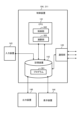
- FIG. 3 is a block diagram that shows a schematic diagram of the electrical connections of the control device.
- the control device 104 can communicate with the excitation power supply 120, cooling device 130, temperature measuring element 50, magnetic field distribution measuring sensor 103, etc. of the electromagnet system 101 via the signal lines described above.
- a CPU (Central Processing Unit) 141 incorporated as the core within the control device 104 reads out a program 301 stored in a storage device 142, expands it in a work area, and executes the program 301 to control each component (control unit 302).
- the CPU 141 executes the program 301 to perform various calculations (calculation unit 303).
- the CPU 141 generates a control signal and controls the target devices (excitation power supply 120, cooling device 130, temperature measuring element 50, magnetic field distribution measuring sensor 103, etc.) via the communication unit 145, which is a communication interface.
- control information include a relational equation for an operation command for the controlled devices based on the difference between the target current and the measured current value, and information on the gain used during feedback control.
- data sensed from the measuring elements is stored in the storage device 142 via the communication unit 145. The sensed data and operation data generated by communication with each control device are displayed by the display device 144.
- the storage device 142 stores data on the arrangement of the line currents of the superconducting electromagnets 110 and 114 (first electromagnets) (i.e., data on the magnetic pole shape of the first electromagnets) since the manufacture of the electromagnet system 101.
- the magnetic fields of the superconducting electromagnets 110 and 114 are calculated from the currents.
- the currents are calculated as lines. That is, the line current is a current considered as a line in this case, and is the basis for calculating the magnetic fields of the superconducting electromagnets 110 and 114.
- the storage device 142 also stores the magnetic field distribution calculated by the CPU 141 from the arrangement of the line currents of the superconducting electromagnets 110 and 114 (first electromagnets).
- the control device 104 does not have a function of displaying the arrangement of the line currents of the superconducting electromagnets 110 and 114 (first electromagnets) on the display device 144, but has a function of displaying the calculated magnetic field distribution as described below.
- data regarding the arrangement of line currents of superconducting electromagnets 110, 114 (first electromagnets) may be stored in memory device 142, or may be stored in an external memory device (such as a server) rather than in memory device 142.
- the storage device 142 includes a random access memory (RAM) that serves as the work area for the CPU 141 to execute the program 301.
- the storage device 142 includes a main storage device and an auxiliary storage device, such as a read only memory (ROM), a RAM, a solid state drive (SSD), or a hard disk drive (HDD).
- the communication unit 145 is composed of, for example, an Ethernet port, a USB port, a GPIB port, a D-sub port, and the like.
- the control device 104 further includes an input device 143 , an output device 146 , and a display device 144 .
- the input device 143 is an input unit having a function of accepting input operations by an operator, and is composed of, for example, a keyboard, a camera, a mouse, a touch panel, a microphone for accepting voice input, etc.
- the operator of the control device 104 can display a desired image on the display device 144, and can display a magnetic field distribution calculated from the line currents of the superconducting electromagnets 110 and 114 (first electromagnets), a measured magnetic field distribution, other measurement data such as temperature, operation data of the control devices, etc.
- the display device 144 is, for example, a liquid crystal display, an organic EL display, etc.
- the output device 146 is, for example, composed of an Ethernet port, a USB (Universal Serial Bus) port, etc.
- the display device 144 and the output device 146 each serve as an output unit, and output data related to the magnetic pole shape of the second electromagnet 321 ( FIG. 5 ) to enable a proposal of the magnetic pole shape of the second electromagnet 321 to be made to the user B.
- the above-mentioned electromagnet system calculation device 311 also has the same hardware configuration as the control device 104, except that it is not connected to the main body of the electromagnet system 101 by the above-mentioned signal line. However, the electromagnet system calculation device 311 does not have the function of the above-mentioned control unit 302, and only has the function of the calculation unit 303.
- the manufacturer 11 executes an electromagnet system calculation method and an electromagnet system manufacturing method.
- the electromagnet system calculation method includes the following first and second steps, and the electromagnet system manufacturing method includes the following first to fourth steps.
- the manufacturer 11 uses the control device 104 or the electromagnet system calculation device 311 to calculate a current distribution indicating the magnetic pole shape of the second electromagnet 321 (FIG. 5) (described later).
- the second electromagnet 321 is manufactured based on the current distribution data that indicates the magnetic pole shape of the second electromagnet 321 calculated in the first step and that is output in the second step.
- the control device 104 or the electromagnet system calculation device 311 stores data on the magnetic pole shape of the first electromagnet (superconducting electromagnets 110, 114) in the memory device 142.
- the calculation unit 303 uses the data on the magnetic pole shape of the first electromagnet (superconducting electromagnets 110, 114) stored in the memory device 142 to calculate a current distribution indicating the magnetic pole shape of the second electromagnet 321, which is used in combination with the first electromagnet (superconducting electromagnets 110, 114) to generate a required magnetic field distribution (magnetic field distribution required by user B), which is a magnetic field distribution in the first electromagnet that is different from the initial magnetic field distribution (magnetic field distribution used by user A).
- FIG. 4 is a flowchart explaining the processing executed by the calculation unit.
- the calculation unit 303 accepts an input of a requested magnetic field (a target magnetic field requested by user B) of the second requested magnetic field space 117 (a magnetic field space requested by user B in the electromagnet system 101; FIG. 5) of user B32 via the input device 143 (step S201).
- This "target magnetic field” is a value that indicates the magnetic field at each location in the second requested magnetic field space 117.
- the second requested magnetic field space 117 may be a space different from the requested magnetic field space 115 of the superconducting electromagnets 110, 114 (first magnet).
- the size of the requested magnetic field space may be different between user A and user B.
- the calculation unit 303 measures the magnetic field distribution generated by the first electromagnet (superconducting electromagnets 110, 114) in the second required magnetic field space 117 using the magnetic field distribution measurement sensor 103 (step S202). Note that when the electromagnet system calculation device 311 is used for this calculation, such measurements are not possible, so data measured by the electromagnet system 101 can be input in step S202.
- the measurement positions of the magnetic field distribution may be the same positions as the distribution of the target magnetic field, but since the distribution of the measured magnetic field can be interpolated using the arrangement of the line current of the first magnetic pole stored in the memory device 142 (data related to the magnetic pole shape of the superconducting electromagnets 110, 114 of the first electromagnet), the number of measurement positions may be less than the number of measurement positions of the distribution of the target magnetic field.
- the symbols I, B, A, etc. represent a matrix that associates position information with values such as current values and magnetic field values.
- current value by the excitation power supply current value by the excitation power supply
- the magnetic field at any position teeth is a coefficient determined by the arrangement of the line current and the distance of the required magnetic field space. Then the magnetic field at the point where it cannot be measured is It can be obtained by correcting the calculated value.
- the calculation unit 303 calculates the difference between the distribution of the measured magnetic field generated by the first magnet (superconducting electromagnets 110, 114) in the second required magnetic field space 117 and the distribution of the target magnetic field (the difference between the measured magnetic field and the required magnetic field at the same position) at each position (step S203).
- the calculation unit 303 takes into consideration the shapes of the superconducting electromagnets 110, 114 (first electromagnets) and inputs from the input device 143 the locations where the line current can be arranged in the magnetic pole shape (hereinafter sometimes referred to as the "second magnetic pole shape") of the second electromagnet 321 ( Figure 5), and limits the locations where the line current can be arranged in the magnetic pole shape of the second electromagnet 321 (step S204).
- the calculation unit 303 solves the inverse problem of the differential magnetic field calculated in S203 (calculate the linear current distribution of the second magnetic pole shape from the required magnetic field) (step S205) using the possible locations of the linear current of the second magnetic pole shape limited in S204 as limiting conditions.
- the inverse problem can be solved by a known solution method for finding the matrix distribution of the linear current from the matrix distribution of the magnetic field, such as Tikhonov regularization.
- the matrix distribution of the linear current found from the inverse problem cannot be uniquely found depending on the solution method, but since the storage device 142 stores the arrangement of the linear current of the magnetic poles of the superconducting electromagnets 110 and 114 (first electromagnets) (data related to the magnetic pole shape of the first electromagnets (superconducting electromagnets 110 and 114)), a more accurate solution of the linear current distribution of the second magnetic pole shape can be found.
- the calculation unit 303 calculates the magnetic field distribution (changed magnetic field) created by the line current distribution of the magnetic pole shape of the first electromagnet (superconducting electromagnets 110, 114) and the line current distribution of the second magnetic pole shape obtained in S205 (step S206).
- the calculation unit 303 calculates the square of the difference between the changed magnetic field and the target magnetic field, and if the square of the difference is less than a preset allowable value (Yes in step S207), the series of processes ends. If the allowable value is exceeded (No in step S207), the calculation unit 303 returns to S204, which considers the arrangement of the second magnetic pole shape, and repeats the following processes. That is, the position of the magnetic field is shifted until it becomes less than the allowable value, and the processes from S204 onwards are tried.
- step S207 the magnetic field distribution (changed magnetic field) created by the line current distribution of the second magnetic pole shape is obtained.
- this second magnetic pole shape is output as electronic data or printed matter in the second step, and the result of the second magnetic pole shape is proposed to user B. Then, once user B has approved the proposed result, the third and fourth steps are executed.
- FIG. 5 is a system configuration diagram showing an example of the configuration of the electromagnet system according to the first embodiment in which the second electromagnet is installed.
- the second electromagnet 204 supports the winding 151 constituting the line current arrangement of the second magnetic pole shape obtained in S205 with a load support 152.
- the winding 151 constituting the line current arrangement of the second magnetic pole shape is made of a conductor, and is connected to an excitation power supply 150 different from the excitation power supply 120 to receive power.
- the configuration of the wire constituting the winding 151 is not particularly limited, and may be, for example, a copper wire or a superconducting wire. However, when a superconducting wire is used, it is necessary to cool it, and therefore the winding 151 must be stored in a container such as a cryostat 160.
- the magnetic field generated by the superconducting electromagnets 110, 114 (first electromagnets) is generally assumed to be a strong magnetic field of several tesla, so when electricity is passed through the windings 151 constituting the second magnetic pole-shaped line current arrangement of the second electromagnet 204 placed in that space, a powerful electromagnetic force acts. For this reason, it is desirable for the load support 152 to be strong enough to support the electromagnetic force formed by the product of the magnetic field strength and the current value. There are no particular limitations on the configuration of the load support 152, but as long as the windings 151 and the load support 152 are insulated by an electrical insulator such as resin, a non-magnetic metal such as stainless steel or an aluminum alloy can be used.
- the storage device 142 stores data on the excitation current of the first and second electromagnets and temperature data of the first and second electromagnets (in the above example, the second electromagnet 321 is not provided with a temperature detection element, but may be provided), and the calculation unit 303 calculates the recommended operating time of the cooling device 130 of the first and second electromagnets based on this data on the excitation current and temperature data (in the above example, the second electromagnet 321 is not provided with a cooling device, but may be provided with one), and the output device 146 and display device 144, which serve as the output unit, output the recommended operating time.
- the calculation unit 303 uses data regarding the magnetic pole shape of the first electromagnet to calculate a current distribution indicating the magnetic pole shape of the second electromagnet 321, which, when used in combination with the first electromagnet (superconducting electromagnets 110, 114), generates a requested magnetic field distribution that is a magnetic field distribution different from the magnetic field distribution requested by user A. Therefore, by proposing this second electromagnet 321 to user B, manufacturing it, and additionally installing it in the electromagnet system 101, it is possible to provide an electromagnet system 101 that meets the needs of user B. Therefore, it is also possible to provide a rental service for the electromagnet system 101.
- the electromagnet system 101 can be provided for rental services by simply making adjustments at low cost in a short time, thereby improving the efficiency of the rental service of the electromagnet system 101. Furthermore, since data regarding the magnetic pole shape of the first electromagnet is stored in advance in the storage device 142, the second electromagnet 321 can be proposed, manufactured, and installed in the electromagnet system 101 with high accuracy and speed.
- the electromagnet system 101 and the electromagnet system calculation device 311 are equipped with an output device 146, which serves as an output section that outputs the magnetic pole shape of the second electromagnet 321 calculated by the calculation section 303, and a display device 144. Therefore, the second electromagnet 321 can be proposed, manufactured, and installed in the electromagnet system 101 with high accuracy and speed.
- the electromagnet system 101 and the electromagnet system calculation device 311 are equipped with an input device 143 that serves as an input unit that accepts input of the magnetic field distribution required by user B. Therefore, the electromagnet system 101 and the electromagnet system calculation device 311 can input the magnetic field distribution required by user B, and then propose, manufacture, and install the electromagnet 321 in the electromagnet system 101.
- the calculation unit 303 can determine the recommended operating time of the cooling device (cooling device 130, etc.) for the first and second electromagnets, and can also suggest the recommended operating time to users A and B.
- a temperature measuring element 50 is placed on the surface of the first electromagnet (superconducting electromagnets 110, 114), the detected temperature transmitted by signal line 171 is stored in memory device 142, and the current of the superconducting coil winding 111 is feedback-controlled by control device 104 based on this detected temperature (in the above example, the second electromagnet 321 is not provided with a temperature measuring element and is not subjected to such control, but a similar control may be performed for the second electromagnet 321 as well). Therefore, the operation of the first and second electromagnets can be appropriately controlled.
- the magnetic field distribution measuring sensor 103 can measure the magnetic field at various positions in the magnetic field space by changing its position using the driving mechanism 106, it is possible to appropriately design the second electromagnet 321 and appropriately control the first and second magnets.
- the second electromagnet 321 is excited by an excitation power supply 150 that is different from the excitation power supply 120 for the first electromagnet. Therefore, it is possible to supply appropriate power to each of the first electromagnet and the second electromagnet 321.
- FIG. 6 is a block diagram explaining the flow of the rental service of the electromagnet system according to the second embodiment.
- the same reference numerals are used for the components and the like that are common to the first embodiment, and detailed explanations are omitted.
- the parties involved in this service are the manufacturer 11 of the electromagnet system 201 (FIG. 7), the owner 12, user C, etc.
- a second electromagnet 321 is additionally installed in the electromagnet system 101 that user A no longer uses, and the electromagnet system 101 is newly rented to a new user B.
- the electromagnet system 201 was used by user C, but the method of using the electromagnet system 201 changed, and a second electromagnet 322 is additionally installed in the electromagnet system 201 to accommodate the change, and the system is allowed to continue to be rented to user C for use.
- the owner 21 of the electromagnet system 201 rents the electromagnet system 201 to the user C (equipment rental) (S13).
- the user C requests the manufacturer 11 or the owner 21 to change the magnetic field realized by the electromagnet system 201 (magnetic field change request) (S21).
- the manufacturer 11 "proposes” the magnetic pole shape of the second electromagnet 322 (second magnetic pole shape) and "installs” the second electromagnet 322 additionally to the existing electromagnet system 201 (S24).
- the magnetic field and operating data of user C stored in the control device 244 of the electromagnet system 201 is provided to the manufacturer 11 (S15), and the manufacturer 11 proposes a more efficient operating method of the electromagnet system 201 to user C (S25).
- the electromagnet system 201 is an electromagnet that uses a superconducting electromagnet, operating the cooling device in accordance with the timing of generating a magnetic field leads to efficient operation.
- the power consumption during cooling is generally several kW (kilowatts) to several tens of kW, whereas a superconducting electromagnet has an electrical resistance of 0 ⁇ during steady-state current flow, so the power consumption of the electromagnet is 0 W.
- the power consumption during cooling is overwhelmingly greater than the power consumption during current flow to generate a magnetic field, and therefore, synchronizing the operation time of the cooling device with the timing of generating a magnetic field leads to highly efficient operation.
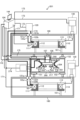
- FIG. 7 is a system configuration diagram showing an example of the configuration of an electromagnet system after the second electromagnet is additionally added.
- a second electromagnet (magnetic field shield) 204 is proposed according to the magnetic field distribution required for the electromagnet system 201, and this is installed in the electromagnet system 201.
- a magnetic field shield is a device that shields a magnetic field and converges magnetic flux. A magnetic field shield can bring a stronger magnetic field to a narrower range.
- the second electromagnet 204 is adopted, but depending on the magnetic field distribution required for the magnet system 201, a wound-shaped second electromagnet may be arranged as in the first embodiment.
- the second electromagnet 204 in this example can be made of, for example, a superconducting bulk material or a material having diamagnetic properties formed by stacking superconducting thin films.
- the material is not limited, for example, high-temperature superconducting substances (YBa 2 Cu 3 O 7- ⁇ , Bi 2 Sr 2 Ca 2 Cu 3 O 10 , etc.), niobium titanium (NbTi) material, niobium tritin (Nb 3 Sn) material, magnesium diboride (MgB 2 ) material, etc. can be used.
- the second electromagnet 204 is a superconductor, it will exhibit the property of shielding a magnetic field when it is cooled below the superconducting transition temperature to enter a superconducting state. Therefore, the second electromagnet 204 is housed in a cryostat 260 and cooled by a cooling device 230. The second electromagnet 204 is subjected to an electromagnetic force in the magnetic field generated by the superconducting electromagnets 110 and 114 (first electromagnets), and is therefore supported in the cryostat 260 by a load support 261.
- cryostat 160 for the superconducting electromagnets 110, 114 and the cryostat 260 for the second electromagnet 204 are separate, but depending on the temperature conditions used, the superconducting electromagnets 110, 114 and the second electromagnet 204 may be housed in the same cryostat 160.
- the second electromagnet 204 converges the magnetic field generated by the superconducting electromagnets 110, 114 (first electromagnets) to amplify the magnetic field in the second required magnetic field space 217.
- the second electromagnet 204 has the characteristic of generating a current so as to shield the magnetic flux in a plane perpendicular to the invading magnetic flux.
- the current distribution of the second electromagnet 204 can be calculated by the control device 244 in the same procedure as in the first embodiment, and the arrangement of the magnetic pole shape of the second electromagnet 204 can be proposed. In FIG.
- the second required magnetic field space 217 is arranged in the cryostat 260, but this configuration is not particularly limited, and a through hole can be opened in the center of the cryostat 260, and the second required magnetic field space 217 can also be arranged in a room temperature environment.
- thermometer or heater can be attached to the thermal conductor 270 connecting the cooling device 230 and the second electromagnet 204, and the temperature of the second electromagnet 204 can be controlled.
- the current density of the shielding current flowing through the second electromagnet 204 takes the value of the superconducting critical current density, and the magnitude of the superconducting critical current density changes depending on the temperature.
- the magnitude of the shielding current can be controlled, and the magnetic field in the second required magnetic field space 217 can be controlled.
- a known control method can be applied as the heater output control method, and for example, PID (Proportional-Integral-Differential) control can be used.
- the second electromagnet 204 which does not require an excitation power supply and amplifies the magnetic field generated by the first electromagnet by shielding it, can also be used as the second electromagnet.
- the electromagnet system 201 can be provided for rental services by simply making adjustments in a short time and at low cost, thereby improving the efficiency of the rental service of the electromagnet system 201.
- the manufacturing cost of the second electromagnet 204 can be reduced.
- the same functions and effects as those of the first embodiment can be achieved by using the same components as those of the first embodiment.
- the present invention is not limited to the above-described embodiments, but includes various modified examples.
- the above-described examples have been described in detail to clearly explain the present invention, and are not necessarily limited to those having all of the configurations described. It is also possible to replace part of the configuration of one embodiment with the configuration of another embodiment, and it is also possible to add the configuration of another embodiment to the configuration of one embodiment. It is also possible to add, delete, or replace part of the configuration of each embodiment with other configurations.
- control lines and information lines shown are those that are considered necessary for the explanation, and not all control lines and information lines in the product are necessarily shown. In reality, it can be considered that almost all components are connected to each other.
- Electromagnet system 101, 201 Electromagnet system 103 Magnetic field distribution measurement sensor (sensor) 106 Drive mechanism 110, 114 Superconducting electromagnet (first electromagnet) 120, 150 Excitation power supply 142 Storage device 143 Input device (input section) 144 Display device (output section) 146 Output device (output section) 301 Program 302 Control unit 303 Calculation unit 311 Electromagnet system calculation device 321, 204 Second electromagnet
Landscapes
- Physics & Mathematics (AREA)
- Electromagnetism (AREA)
- Engineering & Computer Science (AREA)
- Power Engineering (AREA)
- Magnetic Resonance Imaging Apparatus (AREA)
Abstract
電磁石システム(101)は、第1の電磁石となる超伝導電磁石(110),(114)と、第1の電磁石が発生する磁場の磁場分布を計測する磁場分布計測センサ(103)と、第1の電磁石の磁極形状に関するデータを記憶している記憶装置と、第1の電磁石と組み合わせて用いることで前記磁場分布とは異なる磁場分布である要求磁場分布を発生させる第2の電磁石(321)の磁極形状を示す電流分布を、第1の電磁石の磁極形状に関するデータを用いて演算する演算部と、を備えている。
Description
本発明は、電磁石システム、電磁石システム演算方法、電磁石システム製造方法および電磁石システム演算装置に関する。
本技術分野の背景技術として、国際公開2016/133204公報(特許文献1)がある。この公報には、「磁場計測値から、仮想的に配置し、計測位置を囲む電流面を想定し、計測磁場が再現される電流分布(または磁気モーメント分布)を電流ポテンシャルを通して再現し、その再現した磁場分布を含むシミング手法を提供する。磁場計測装置によって取得された磁場分布を再現するような磁気モーメントもしくは電流分布を、予め定められた閉曲面上で推定し、前記推定された磁気モーメントもしくは電流分布から前記閉曲面内に存在する任意点の磁場分布を推定する。そして、前記推定された磁場分布に基づき、前記任意点の磁場分布を修正する補正磁場を生じさせるシム磁性体の分布を出力する。」と記載されている(要約参照)。
別の背景技術として、特開2021-26695号公報(特許文献2)がある。この公報には、「レンタル機材管理システムの管理サーバは、プロセッサとメモリを有し、レンタルされる機材を管理する。プロセッサは、機材のそれぞれの稼働情報を収集して、稼働情報が所定の稼働条件を満たしていない機材を融通可能な機材として抽出し、抽出された機材を利用している地理情報を含めて融通機材情報を生成する。プロセッサは、機材を利用する需要情報を受け付けて、需要情報に含まれる地理情報と、融通機材情報に含まれる地理情報を比較して、所定の地理条件を満たす融通機材情報の機材を融通可能性情報として生成する。」と記載されている(要約参照)。
しかしながら、特許文献1,2に開示の技術は、電磁石システムのレンタルシステムの効率を高めるという観点からは改善の余地があった。
そこで、本発明は、電磁石システムのレンタルサービスの効率を高めることができる電磁石システム、電磁石システム演算方法、電磁石システム製造方法および電磁石システム演算装置を提供することを課題とする。
そこで、本発明は、電磁石システムのレンタルサービスの効率を高めることができる電磁石システム、電磁石システム演算方法、電磁石システム製造方法および電磁石システム演算装置を提供することを課題とする。
上記課題を解決するため、本発明は、第1の電磁石と、前記第1の電磁石が発生する磁場の磁場分布を計測するセンサと、前記第1の電磁石の磁極形状に関するデータを用いて、前記第1の電磁石と組み合わせて用いることで前記磁場分布とは異なる磁場分布である要求磁場分布を発生させる第2の電磁石の磁極形状を示す電流分布を演算する演算部と、を備えている。
本発明によれば、電磁石システムのレンタルサービスの効率を高めることができる。
上記した以外の課題、構成及び効果は、以下の実施形態の説明により明らかにされる。
上記した以外の課題、構成及び効果は、以下の実施形態の説明により明らかにされる。
以下、本発明の実施形態について図面を用いて説明する。
まず、本実施形態の課題について説明する。
本実施形態では、電磁石を備え、この電磁石で発生させる磁場によって所定の目的を達成するためのシステムを「電磁石システム」と呼ぶことにする。電磁石システムでは、コイル状に巻線を巻いた電磁石に通電することで磁場を発生させる。
近年、電磁石システムは、医療分野、核融合分野、電動化分野等の様々な分野での研究開発等に使用されている。この研究開発等に使用される電磁石システムは、これまでは、用途に合わせて、要求される磁場を発生させることができるように1台1台設計され、製造されてきた。また、電磁石システムは、研究用途によっては高精度の磁場が要求され、製造誤差等のシステムごとのばらつきを考慮に入れた磁場の調整が必要となる。
まず、本実施形態の課題について説明する。
本実施形態では、電磁石を備え、この電磁石で発生させる磁場によって所定の目的を達成するためのシステムを「電磁石システム」と呼ぶことにする。電磁石システムでは、コイル状に巻線を巻いた電磁石に通電することで磁場を発生させる。
近年、電磁石システムは、医療分野、核融合分野、電動化分野等の様々な分野での研究開発等に使用されている。この研究開発等に使用される電磁石システムは、これまでは、用途に合わせて、要求される磁場を発生させることができるように1台1台設計され、製造されてきた。また、電磁石システムは、研究用途によっては高精度の磁場が要求され、製造誤差等のシステムごとのばらつきを考慮に入れた磁場の調整が必要となる。
ここで、前記特許文献1には、電磁石システムについて製造誤差による磁場のばらつきの調整を行うことを目指した技術について開示されている。このように、電磁石システムを製作するに際しては、製造誤差等の装置ごとのばらつきを考慮に入れた磁場の調整が必要となる。
一方で、電磁石システムは特定の研究用途等に合わせて製造されるため、その研究用途等が達成されると、今まで使用されていた電磁石システムは、遊休状態となって該当の研究機関等で保有される状態となることがあった。
一方で、電磁石システムは特定の研究用途等に合わせて製造されるため、その研究用途等が達成されると、今まで使用されていた電磁石システムは、遊休状態となって該当の研究機関等で保有される状態となることがあった。
これに対して、一般機材では、そういった遊休状態を回避するために、レンタルサービス等による機材の遊休状態の回避の工夫が考えられている。前記特許文献2の技術では、建設機材のレンタルサービスにおいて、建設機材の稼働情報や位置情報まで管理して、レンタルサービスにおける建設機材の稼働率の向上を図ることを目指している。
しかしながら、電磁石システムにおいては、その用途に応じて要求される磁場が異なることが多く、同じ機器構成の機材を提供する既存のレンタルサービスでは、ある用途での使用が終了した電磁石システムを次の用途に使用しようとすることは困難な場合がほとんどである。このような問題に対処するために、これまでは、用途ごとに電磁石システムを1台1台製造するしかなかった。
しかしながら、電磁石システムにおいては、その用途に応じて要求される磁場が異なることが多く、同じ機器構成の機材を提供する既存のレンタルサービスでは、ある用途での使用が終了した電磁石システムを次の用途に使用しようとすることは困難な場合がほとんどである。このような問題に対処するために、これまでは、用途ごとに電磁石システムを1台1台製造するしかなかった。
しかし、電磁石システムにおいても、レンタルサービスを行うようにして、ある用途でのレンタルを終了した電磁石システムを次の用途のためにレンタルでの提供を可能とすることを、短時間で低コストによる電磁石システムの調整を行うだけで実現できるようにしたい。
以下では、短時間で低コストによる調整を行うだけで電磁石システムをレンタルサービスに提供できるようにして、電磁石システムのレンタルサービスの効率を高めることができるようにした技術について説明する。
以下では、短時間で低コストによる調整を行うだけで電磁石システムをレンタルサービスに提供できるようにして、電磁石システムのレンタルサービスの効率を高めることができるようにした技術について説明する。
図1は、本実施形態1に係る電磁石システムのレンタルサービスの流れを説明するブロック図である。図1に示すように、当該サービスは、電磁石システム101(図2)の製造、調整を行う製造事業者11、製造事業者11が製造、調整(保守点検を含む)する電磁石システム101の所有者12(電磁石システム101のリース会社、レンタル会社等)が使用する。また、前記サービスは、電磁石システム101を所有者12からレンタル(リース等の様々な貸し出し形態も含めて、以下では「レンタル」という)されて使用する使用者A、使用者Bも使用する。ここで使用者は使用者A,Bの2者だけを記載しているが、使用者はより多数存在していてもよい。以下では、所有者21がレンタルで使用者Aに提供した電磁石システム101の使用者Aでの使用が終了し、次に同じ電磁石システム101を所有者21が使用者Bにレンタルする局面を考える。ここで、使用者Bが電磁石システム101に求める磁場(要求磁場)は、使用者Aの要求磁場とは異なっているのが通例である。そのため、所有者21は、使用者Aが使用していた電磁石システム101をそのまま使用者Bにレンタルするのでは、使用者Bのニーズには答えられない。
まず、製造事業者11は、所有者21に電磁石システム101を「装置提供」し、また、電磁石システム101の「保守点検」のサービスを提供する(ステップS11)。電磁石システム101の所有者21は、電磁石システム101の「稼働情報」等の電磁石システム101の保守に必要な情報(電磁石システム101の動作時の磁場の情報や、超伝導システムの冷却装置による冷却時間等)を製造事業者11に提供する(ステップS12)。これは、製造事業者11は、電磁石システム101の製品情報は知っているが、どのように電磁石システム101が使用されているかは知らず、それは電磁石システム101のユーザ側でしか知りえない情報だからである。
所有者21は、電磁石システム101を使用者Aに貸し出す(装置貸出)(ステップS13)。電磁石システム101の使用者Aが、電磁石システム101を使用したときに電磁石システム101の磁場分布計測センサ(センサ)103(図2)によって計測される磁場のデータ、および電磁石システム101の運転のデータ(磁場・運転データ)は電磁石システム101の制御装置104(図2)に記憶される(S15)。使用者Aが電磁石システム101に要求する磁場と異なる磁場(要求磁場)を同じ電磁石システム101に要求する使用者Bに対して、製造事業者11は、電磁石システム101に最初から設置されている第1の電磁石(超伝導電磁石110,114(図2))に追加で設置される第2の電磁石321(図5)の磁極形状の「提案」を行う(ステップS14)。すなわち、使用者Bは電磁石システム101への要求磁場が使用者Aとは異なる。そこで、製造事業者11は、電磁石システム101に付加的に設置することで使用者Bの要求磁場を実現することができる第2の電磁石321の磁極形状を提案し、当該第2の電磁石321を製造して、当該電磁石システム101に付加的に「設置」する(ステップS14)。
また、製造事業者11は、電磁石システム演算装置311を備えていてもよい。後記するように製造事業者11は、所定の演算処理を行うが、この演算は、後記する電磁石システム101の制御装置104(図2)で行ってもよいし、電磁石システム演算装置311で行ってもよい。
図2は、本実施形態1に係る電磁石システムの一構成例を示すシステム構成図である。電磁石システム101は、例えば、磁場環境下で所定の物の検証をしたい、均一な磁場空間であって所定の装置が入る大型の空間が欲しい等という需要に応えるものである。図2に示す例は、第1の電磁石として超伝導電磁石110,114を設置した場合の例である。本例では、超伝導電磁石110と超伝導電磁石114とは上下に配置されている。超伝導電磁石110と超伝導電磁石114とは基本的に同じ構成であり、それぞれの共通の部材には同じ符号を付している。超伝導電磁石110は、上下に配置されたクライオスタット160の内部に荷重支持体161を介して配置される。超伝導電磁石110は巻き芯112、超伝導コイル巻き線111、冷却部材113を備えている。超伝導電磁石114も同様の構成である。
クライオスタット160は、公知の極低温用真空容器等を適用することが可能であり、例えば、ステンレスやアルミ合金等の金属、強化繊維プラスチック(FRP:Fiber-Reinforced Plastics)等で形成される。
荷重支持体161は、その構成が限定されるものではないが、熱侵入量の低減と強大な電磁力の支持という機能が必要となることから熱伝導率が小さく、比較的強度を有する材料を使うのが望ましい。例えば、FRP等が好ましい。
荷重支持体161は、その構成が限定されるものではないが、熱侵入量の低減と強大な電磁力の支持という機能が必要となることから熱伝導率が小さく、比較的強度を有する材料を使うのが望ましい。例えば、FRP等が好ましい。
超伝導コイル巻き線111は、超伝導パワーリード122a,122bを介して、導入端子121a,121b、ひいては導線174に接続されている。導線174は励磁電源120と超伝導電磁石114,110とを接続しており、励磁電源120を運転するための制御信号が、信号線172を介して制御装置104から励磁電源120に送られる。その一方で、励磁電源120の運転時の電流値、電圧値等は信号線172を介して制御装置104に送信され、記憶される。
超伝導コイル巻き線111に使われる線材は、その構成が特に限定されるものではないが、例えば、銅酸化物系の高温超電導物質(YBa2Cu3O7-δ,Bi2Sr2Ca2Cu3O10等)からなる線材、ニオブチタン(NbTi)材、ニオブ三スズ(Nb3Sn)材、ニホウ化マグネシウム(MgB2)材等によって形成されることが好ましい。なお、超伝導コイル巻き線111に使われる線材は、その表面が、例えば、ガラス等の耐熱性材料、絶縁性材料で被覆されていてもよい。
冷却部材113は、熱良導体170を介して冷却装置130と接続される。冷却装置130は、制御装置104と信号線173を介して接続され、制御装置104により運転が制御され、その運転データが制御装置104に送信されて、記憶される。
冷気を伝える部材である熱良導体170は、例えば、銅、銀、アルミニウム等で形成されることが好ましい。熱良導体170は、単一の熱良導体で形成されていてもよいし、複数の熱良導体を組み合わせて形成されていてもよく、必要に応じて任意の態様をとることが可能である。
冷気を伝える部材である熱良導体170は、例えば、銅、銀、アルミニウム等で形成されることが好ましい。熱良導体170は、単一の熱良導体で形成されていてもよいし、複数の熱良導体を組み合わせて形成されていてもよく、必要に応じて任意の態様をとることが可能である。
冷却装置130は、公知の構成のものを適用することが可能であり、例えば、ギンツブルグ-マクマホン冷凍機、スターリング冷凍機、パルス管冷凍機、等の冷凍機を適用することができる。なお、冷却装置130、熱良導体170、あるいは冷却部材113には、温度調節をするためのヒータや温度計測素子が設けられていてもよい。その場合、ヒータ331や温度計測素子332によって計測された計測結果は、制御装置104へと送信され、冷却装置130の冷却やヒータの加熱が制御装置104によりフィードバック制御される。
また、超伝導コイル巻き線111等、第1の電磁石の表面に温度計測素子50を配置し、信号線171によって送信される検出温度を記憶装置142に記憶し、この検出温度に基づいて、制御装置104より超伝導コイル巻き線111の電流をフィードバック制御している。
温度計測素子50は、測定対象となる超伝導コイル巻き線111等に樹脂等で接着することが熱抵抗を小さくするため好ましいが、接着方法は特に限定されるものではなく、ばね等で押し当てられる圧着でもよい。温度計測素子50は、公知の構成のものを適用することが可能であり、例えば、クロメル・コンスタンタン、金鉄熱電対、抵抗測定型温度センサ等を用いることができる。
温度計測素子50は、測定対象となる超伝導コイル巻き線111等に樹脂等で接着することが熱抵抗を小さくするため好ましいが、接着方法は特に限定されるものではなく、ばね等で押し当てられる圧着でもよい。温度計測素子50は、公知の構成のものを適用することが可能であり、例えば、クロメル・コンスタンタン、金鉄熱電対、抵抗測定型温度センサ等を用いることができる。
電磁石システム101においては、励磁電源120によって、超伝導電磁石110,114に通電することで超伝導電磁石110,114から磁場を発生させることができる。この発生する磁場は、要求磁場空間(使用者が所望の磁場を発生させたい空間)115内で磁場分布計測センサ(センサ)103を使って計測する。磁場分布計測センサ103は、間隔を空けて配置された複数のホール素子、NMRセンサ等により実現することができる。測定した磁場計測データは信号線116を介して制御装置104に送信して、記憶する。
磁場分布計測センサ103は、駆動機構106、シャフト109と締結することで、駆動機構106により移動可能で、要求磁場空間115内を移動して、その磁場分布を計測することができる。駆動機構106は、例えば、超伝導電磁石110のクライオスタット160下部等に支持体107を介して支持されている。この駆動機構106も信号線175を介して制御装置104によって制御が可能である。駆動機構106は、磁場中での動作が必要なため、磁場の影響を受けにくい公知の超音波モータなどを利用することが好ましい。シャフト109も磁場中での使用となるので、非磁性体の一般的な金属材料製やFRP製のシャフトを用いることが好ましい。
次に、電磁石システム101を制御する制御装置104の構成を説明する。図3は、制御装置の電気的な接続を模式的に示すブロック図である。前記したように制御装置104は、電磁石システム101の励磁電源120、冷却装置130、温度計測素子50、磁場分布計測センサ103等と前記した各信号線を介して通信することができる。図3に示すように、制御装置104内に中枢として組みこまれているCPU(Central Processing Unit)141は、記憶装置142に記憶されるプログラム301を読み出して、ワークエリアに展開し、当該プログラム301を実行することで、各構成要素を制御する(制御部302)。また、後記するように、CPU141は、当該プログラム301を実行することで、各種演算を行う(演算部303)。
CPU141は、制御信号を生成し、通信インターフェイスである通信部145を介して対象機器(励磁電源120、冷却装置130、温度計測素子50、磁場分布計測センサ103等)を制御する。制御情報は、例えば、目標電流と計測電流値との差分に基づいた制御対象機器に対する動作指令の関係式、フィードバック制御の際に使用するゲインの情報等が挙げられる。また、計測素子(温度計測素子50や磁場分布計測センサ103等)からセンシングされたデータは、通信部145を介して記憶装置142に格納される。センシングされたデータや各制御機器との通信で生じる運転データは、表示装置144によって表示される。
記憶装置142は、超伝導電磁石110,114(第1の電磁石)の線電流の配置に関するデータ(すなわち、第1の電磁石の磁極形状に関するデータ)を電磁石システム101の製造時から記憶している。ここで超伝導電磁石110,114の磁場は電流から計算される。磁場を計算するとき電流は線として計算する。すなわち、線電流とは、この場合の線と見立てた電流であって、超伝導電磁石110,114磁場を計算する基礎となる。この超伝導電磁石110,114(第1の電磁石)の線電流の配置から、CPU141によって計算される磁場分布も、記憶装置142は、記憶している。制御装置104は、表示装置144に、超伝導電磁石110,114(第1の電磁石)の線電流の配置を表示する機能を持っていないが、後記するように計算される磁場分布を表示する機能を有している。
なお、超伝導電磁石110,114(第1の電磁石)の線電流の配置に関するデータなどは、記憶装置142に記憶されていてもよいし、記憶装置142ではなく、外部の記憶装置(サーバ等)に記憶されていてもよい。
なお、超伝導電磁石110,114(第1の電磁石)の線電流の配置に関するデータなどは、記憶装置142に記憶されていてもよいし、記憶装置142ではなく、外部の記憶装置(サーバ等)に記憶されていてもよい。
記憶装置142は、CPU141がプログラム301を実行するための前記のワークエリアとなるRAM(Random Access Memory)を備えている。記憶装置142は、例えば、ROM(Read Only Memory)、RAM、SSD(Solid State Drive)、HDD(Hard Disk Drive)等の主記憶装置および補助記憶装置を備えている。
通信部145は、例えば、イーサネットポート、USBポート、GPIBポート、D-subポート等で構成される。
通信部145は、例えば、イーサネットポート、USBポート、GPIBポート、D-subポート等で構成される。
制御装置104は、さらにそれぞれ入力装置143と、出力装置146と、表示装置144とを備えている。
入力装置143は、入力部となるもので、操作者による入力操作を受け付ける機能を備えており、例えば、キーボード、カメラ、マウス、タッチパネル、音声入力を受け付けるマイク等で構成される。制御装置104の操作者は、入力装置143を操作することで、表示装置144に所望の画像を表示させて超伝導電磁石110,114(第1の電磁石)の線電流から計算される磁場分布や計測した磁場分布、その他の温度等の計測データや制御機器の運転データ等を表示することができる。
入力装置143は、入力部となるもので、操作者による入力操作を受け付ける機能を備えており、例えば、キーボード、カメラ、マウス、タッチパネル、音声入力を受け付けるマイク等で構成される。制御装置104の操作者は、入力装置143を操作することで、表示装置144に所望の画像を表示させて超伝導電磁石110,114(第1の電磁石)の線電流から計算される磁場分布や計測した磁場分布、その他の温度等の計測データや制御機器の運転データ等を表示することができる。
表示装置144は、例えば、液晶ディスプレイ、有機ELディスプレイ等である。出力装置146は、例えば、イーサネットポート、USB(Universal Serial Bus)ポート等から構成される。表示装置144、出力装置146は、それぞれが出力部となるものであり、第2の電磁石321(図5)の磁極形状に関するデータを出力して、第2の電磁石321の磁極形状の提案を使用者Bに行うことを可能とする。
また、前記した電磁石システム演算装置311も、電磁石システム101の本体と前記した信号線で結ばれていない他は、ハードウェア構成は制御装置104と同様である。しかし、電磁石システム演算装置311は、前記の制御部302の機能を備えておらず、演算部303の機能のみを備える。
また、前記した電磁石システム演算装置311も、電磁石システム101の本体と前記した信号線で結ばれていない他は、ハードウェア構成は制御装置104と同様である。しかし、電磁石システム演算装置311は、前記の制御部302の機能を備えておらず、演算部303の機能のみを備える。
次に、製造事業者11が行う作業について説明する。製造事業者11は、電磁石システム演算方法および電磁石システム製造方法を実行する。電磁石システム演算方法は、次の第1工程および第2工程を備え、電磁石システム製造方法は、次の第1工程~第4工程を備える。
(1)第1工程
製造事業者11は、制御装置104または電磁石システム演算装置311を用いて、第2の電磁石321(図5)の磁極形状を示す電流分布を演算する(後記)。
製造事業者11は、制御装置104または電磁石システム演算装置311を用いて、第2の電磁石321(図5)の磁極形状を示す電流分布を演算する(後記)。
(2)第2工程
第1工程で演算した前記第2の電磁石321の磁極形状を示す電流分布を表示装置144、出力装置146で出力する。
第1工程で演算した前記第2の電磁石321の磁極形状を示す電流分布を表示装置144、出力装置146で出力する。
(3)第3工程
第2工程で出力した、第1工程で演算した第2の電磁石321の磁極形状を示す電流分布のデータに基づいて第2の電磁石321を製造する。
第2工程で出力した、第1工程で演算した第2の電磁石321の磁極形状を示す電流分布のデータに基づいて第2の電磁石321を製造する。
(4)第4工程
第3工程で製造した第2の電磁石321やその周辺機器を電磁石システム101に適切に設置する。
第3工程で製造した第2の電磁石321やその周辺機器を電磁石システム101に適切に設置する。
次に、前記第1工程における演算の内容を詳細に説明する。制御装置104または電磁石システム演算装置311は、記憶装置142において、第1の電磁石(超伝導電磁石110,114)の磁極形状に関するデータを記憶している。演算部303によって、第1の電磁石(超伝導電磁石110,114)と組み合わせて用いることで当該第1の電磁石に当初の磁場分布(使用者Aで使用していた磁場分布)とは異なる磁場分布である要求磁場分布(使用者Bが要求する磁場分布)を発生させる第2の電磁石321の磁極形状を示す電流分布を、記憶装置142に記憶されている第1の電磁石(超伝導電磁石110,114)の磁極形状に関するデータを用いて演算する。
かかる演算の例についてより詳細に説明する。図4は、演算部が実行する処理を説明するフローチャートである。まず、演算部303は、入力装置143により、使用者B32の第2の要求磁場空間117(使用者Bが電磁石システム101において求める磁場空間。図5)の要求磁場(使用者Bが求める目標磁場)の入力を受け付ける(ステップS201)。この「目標磁場」は第2の要求磁場空間117における当該空間の各箇所のそれぞれではこのような磁場であるという値である。ここで第2の要求磁場空間117は、超伝導電磁石110,114(第1の磁石)の要求磁場空間115と異なる空間であってもよい。例えば使用者Aと使用者Bとで要求磁場空間の大きさが違ってもよい。
演算部303は、第2の要求磁場空間117における第1の電磁石(超伝導電磁石110,114)が発生する磁場分布を磁場分布計測センサ103で計測する(ステップS202)。なお、電磁石システム演算装置311を本演算に用いる場合は、このような計測ができないので、電磁石システム101で計測したデータをステップS202で入力するようにすればよい。磁場分布の計測位置は、目標磁場の分布と同じ位置であることが望ましいが、記憶装置142が格納している第1の磁極の線電流の配置(第1の電磁石の超伝導電磁石110,114の磁極形状に関するデータ)により、計測磁場の分布は補間することができるので、目標磁場の分布の計測位置の数より少なくてもよい。
ここで、計測磁場の分布の補間方法を次に示す。以下の説明で斜体の太字で示すI,B,A等の記号は、位置情報と電流値、磁場値等の値とを対応付けて表化したマトリックスである。第1の磁極の線電流を

(励磁電源による電流値)とすると、任意の位置の磁場

は、

で求めることができる。ここで、

は、線電流の配置と、要求磁場空間の距離によって決まる係数である。任意位置での計測磁場を

とすると計測できない箇所の磁場は、

で計算値から補正して求めることができる。
(励磁電源による電流値)とすると、任意の位置の磁場
は、
で求めることができる。ここで、
は、線電流の配置と、要求磁場空間の距離によって決まる係数である。任意位置での計測磁場を
とすると計測できない箇所の磁場は、
で計算値から補正して求めることができる。
次に、演算部303は、第2の要求磁場空間117における第1の磁石(超伝導電磁石110,114)が発生する計測磁場の分布と、目標磁場の分布との差分(同じ位置での計測磁場と要求磁場との差)を各位置で計算する(ステップS203)。
次に、演算部303は、超伝導電磁石110,114(第1の電磁石)の形状を考慮に入れ、第2の電磁石321(図5)の磁極形状(以下、「第2の磁極形状」ということがある)の線電流の配置可能な場所を入力装置143から入力し、第2の電磁石321の磁極形状の線電流の配置可能な場所を限定する(ステップS204)。
次に、演算部303は、超伝導電磁石110,114(第1の電磁石)の形状を考慮に入れ、第2の電磁石321(図5)の磁極形状(以下、「第2の磁極形状」ということがある)の線電流の配置可能な場所を入力装置143から入力し、第2の電磁石321の磁極形状の線電流の配置可能な場所を限定する(ステップS204)。
次に、演算部303は、S204で限定した第2の磁極形状の線電流の配置可能な場所を限定条件とし、S203で計算した差分磁場の逆問題を解く(要求磁場から第2の磁極形状の線電流分布を計算する)(ステップS205)。逆問題の解法は、ティホノフの正則化等、磁場のマトリクス分布から線電流のマトリクス分布を求める公知の解法を用いることができる。逆問題から求められる線電流のマトリクス分布は解法によっては一意に求めることができないが、超伝導電磁石110,114(第1の電磁石)の磁極の線電流の配置(第1の電磁石(超伝導電磁石110,114)の磁極形状に関するデータ)を記憶装置142が記憶していることで、より高精度な第2の磁極形状の線電流の分布の解を求めることができる。
次に、演算部303は、第1の電磁石(超伝導電磁石110,114)の磁極形状の線電流の分布とS205で求めた第2の磁極形状の線電流の分布とが作り出す磁場分布(変更磁場)を計算する(ステップS206)。
次に、演算部303は、変更磁場と目標磁場の差分の2乗を計算し、その値が予め設定された許容値未満であれば(ステップS207のYes)、一連の処理を終了する。演算部303は、許容値を超過していれば(ステップS207のNo)、第2の磁極形状の配置を検討するS204に戻り、以下の処理を繰り返す。すなわち、許容値未満になるまで磁場の位置をずらしてS204以下の処理をトライする。
次に、演算部303は、変更磁場と目標磁場の差分の2乗を計算し、その値が予め設定された許容値未満であれば(ステップS207のYes)、一連の処理を終了する。演算部303は、許容値を超過していれば(ステップS207のNo)、第2の磁極形状の配置を検討するS204に戻り、以下の処理を繰り返す。すなわち、許容値未満になるまで磁場の位置をずらしてS204以下の処理をトライする。
このようにして、ステップS207のYesにより前記第1工程が完了し、第2の磁極形状の線電流分布が作る磁場分布(変更磁場)が求められる。その後は、この第2の磁極形状を前記第2工程で電子データや印刷物として出力し、その第2の磁極形状の結果を使用者Bに提案する。そして提案結果に使用者Bの了承を得られたら、前記第3工程、第4工程を実行する。
次に、このような工程を経て製造した第2の電磁石204を付加的に設置した状態の図2に示す電磁石システム101について説明する。図5は、第2の電磁石を設置した本実施形態1に係る電磁石システムの一構成例を示すシステム構成図である。
第2の電磁石204は、S205で求めた第2の磁極形状の線電流の配置を構成する巻き線151を荷重支持体152で支持している。第2の磁極形状の線電流配置を構成する巻き線151は導線から成り、励磁電源120とは異なる励磁電源150に接続されて給電される。巻き線151を構成する線材は、その構成が特に限定されるものではないが、例えば、銅線や超伝導線材を用いることができる。ただし、超伝導線材を用いる場合には、冷却する必要があるため、クライオスタット160のような容器内に、巻き線151を収納する必要がある。
第2の電磁石204は、S205で求めた第2の磁極形状の線電流の配置を構成する巻き線151を荷重支持体152で支持している。第2の磁極形状の線電流配置を構成する巻き線151は導線から成り、励磁電源120とは異なる励磁電源150に接続されて給電される。巻き線151を構成する線材は、その構成が特に限定されるものではないが、例えば、銅線や超伝導線材を用いることができる。ただし、超伝導線材を用いる場合には、冷却する必要があるため、クライオスタット160のような容器内に、巻き線151を収納する必要がある。
超伝導電磁石110,114(第1の電磁石)によって発生する磁場は一般には数テスラの強磁場であることを想定しているため、その空間内に配置する第2の電磁石204の第2の磁極形状の線電流の配置を構成する巻き線151に通電すると、強大な電磁力が作用する。そのため、荷重支持体152は、磁場の強度と電流値の積から成る電磁力に対して支持できる強度のあるものが望ましい。荷重支持体152の構成は特に限定されるものではないが、巻き線151と荷重支持体152の間を樹脂等電気絶縁体によって絶縁していれば、ステンレスやアルミ合金等の非磁性体の金属を用いることができる。
記憶装置142は、第1および第2の電磁石の励磁電流に関するデータと、第1および第2の電磁石の温度データを記憶(前記の例では、第2の電磁石321に温度検出素子が設けられていないが、設けてもよい)し、演算部303は、これらの励磁電流に関するデータと温度データとに基づいて、第1および第2の電磁石の冷却装置130(前記の例では第2の電磁石321には冷却装置が設けられていないが、設けられていてもよい)の運転推奨時間を求め、出力部となる出力装置146、表示装置144は、その運転推奨時間を出力する。
以上説明した本実施形態の電磁石システム101、電磁石システム演算装置311によれば、演算部303は、第1の電磁石(超伝導電磁石110,114)と組み合わせて用いることで、使用者Aの要求していた磁場分布とは異なる磁場分布である要求磁場分布を発生させる第2の電磁石321の磁極形状を示す電流分布を、第1の電磁石の磁極形状に関するデータを用いて演算する。そのため、この第2の電磁石321を使用者Bに提案し、製造し、付加的に電磁石システム101に設置することで、使用者Bのニーズに合った電磁石システム101を提供することができる。そのため、電磁石システム101についてもレンタルサービス業務を可能とすることができる。
この場合に電磁石システム101の使用を使用者Aから使用者Bに変更するに際し、超伝導電磁石110,114を新たな電磁石に全取り換えする必要はない。第2の電磁石321を製造し、付加的に電磁石システム101に取り付けるだけで使用者Cの要求に応えている。そのため、超伝導電磁石110,114を全取り換えしないでよいので、新仕様の電磁石システム101を用意するのに大きな製造コストや長い準備工程を必要としない。
そのため、短時間で低コストによる調整を行うだけで電磁石システム101をレンタルサービスに提供できるようにして、電磁石システム101のレンタルサービスの効率を高めることができる。
また、第1の電磁石の磁極形状に関するデータは、予め記憶装置142に記憶されているので、高精度かつ迅速に第2の電磁石321を提案し、製造し、電磁石システム101に設置することができる。
また、第1の電磁石の磁極形状に関するデータは、予め記憶装置142に記憶されているので、高精度かつ迅速に第2の電磁石321を提案し、製造し、電磁石システム101に設置することができる。
電磁石システム101、電磁石システム演算装置311は、演算部303で演算した第2の電磁石321の磁極形状を出力する出力部となる出力装置146、表示装置144を備えている。そのため、高精度かつ迅速に第2の電磁石321を提案し、製造し、電磁石システム101に設置することができる。
電磁石システム101、電磁石システム演算装置311は、使用者Bの要求磁場分布の入力を受け付ける入力部となる入力装置143を備えている。そのため、電磁石システム101、電磁石システム演算装置311で使用者Bの要求磁場分布の入力を行って、電磁石321を提案し、製造し、電磁石システム101に設置することができる。
また、演算部303は、前記第1および第2の電磁石の冷却装置(冷却装置130等)の運転推奨時間を求めることができるので、その運転推奨時間を使用者A,Bにも提案することができる。
また、第1の電磁石(超伝導電磁石110,114)の表面に温度計測素子50を配置し、信号線171によって送信される検出温度を記憶装置142に記憶し、この検出温度に基づいて、制御装置104によって超伝導コイル巻き線111の電流をフィードバック制御している(前記の例では、第2の電磁石321には温度計測素子を設けておらず、このような制御を行っていないが、同様の制御を第2の電磁石321についても行ってよい)。したがって、第1、第2の電磁石の動作を適切に制御することができる。
また、磁場分布計測センサ103は、駆動機構106により位置を可変して、磁場空間の様々な位置の磁場を測定できるので、第2の電磁石321を適切に設計したり、第1、第2の磁石を適切に制御したりすることができる。
また、第2の電磁石321は、第1の電磁石の励磁電源120とは異なる励磁電源150で励磁する。そのため、第1の電磁石、第2の電磁石321それぞれに適切な電力を供給することができる。
また、第2の電磁石321は、第1の電磁石の励磁電源120とは異なる励磁電源150で励磁する。そのため、第1の電磁石、第2の電磁石321それぞれに適切な電力を供給することができる。
図6は、本実施形態2に係る電磁石システムのレンタルサービスの流れを説明するブロック図である。なお、第2実施形態において、第1実施形態と共通する部材等については、共通の符号を用い、詳細な説明は省略する。
図6に示すように、本サービスにかかわるのは、電磁石システム201(図7)の製造事業者11、所有者12、使用者C等である。実施形態1では、使用者Aが使用しなくなった電磁石システム101に第2の電磁石321を付加的に設置して、新たに電磁石システム101を新たな使用者Bにレンタルする例であった。本実施形態2では、電磁石システム201を使用者Cが使用していたが、電磁石システム201の使用方法が変更となり、その変更に合わせて電磁石システム201に第2の電磁石322を付加的に設置して、引き続き使用者Cにレンタル使用させ続ける例である。
まず、電磁石システム201の所有者21は、使用者Cに電磁石システム201をレンタルする(装置貸出)(S13)。使用者Cは当初の電磁石システム201の用途を達成した後に、製造事業者11もしくは所有者21に電磁石システム201で実現する磁場の変更を要求する(磁場変更要求)(S21)。その要求に対して製造事業者11は、第2の電磁石322の磁極形状(第2の磁極形状)の「提案」を行い、既存の電磁石システム201に、第2の電磁石322を付加的に「設置」する(S24)。
また、電磁石システム201の制御装置244内に格納されている使用者Cの磁場・運転データは製造事業者11に提供され(S15)、電磁石システム201のより効率的な運転方法を製造事業者11が使用者Cに提案する(S25)。
例えば、電磁石システム201が超伝導電磁石を使用する電磁石としている場合、磁場を発生させるタイミングにあわせて冷却装置を稼働させることが運転の効率化につながる。超伝導電磁石の場合、その冷却時の電力消費は一般に数kW(キロワット)~数10kWであるのに対して、超伝導電磁石は定常電流通電時、電気抵抗が0Ωであるので、電磁石の電力消費は0Wである。つまり、磁場を発生させるための通電時の電力消費と比べて冷却時の電力消費は、圧倒的に大きく、冷却装置を運転する時間と、磁場を発生させるタイミングとをあわせて実施することが高効率の運転につながる。
例えば、電磁石システム201が超伝導電磁石を使用する電磁石としている場合、磁場を発生させるタイミングにあわせて冷却装置を稼働させることが運転の効率化につながる。超伝導電磁石の場合、その冷却時の電力消費は一般に数kW(キロワット)~数10kWであるのに対して、超伝導電磁石は定常電流通電時、電気抵抗が0Ωであるので、電磁石の電力消費は0Wである。つまり、磁場を発生させるための通電時の電力消費と比べて冷却時の電力消費は、圧倒的に大きく、冷却装置を運転する時間と、磁場を発生させるタイミングとをあわせて実施することが高効率の運転につながる。
図7は、第2の電磁石を付加的に追加後の電磁石システムの一構成例を示すシステム構成図である。超伝導電磁石110,114(第1の電磁石)が発生する磁場に対して使用者Cからの磁場の変更要求があった場合、新たに電磁石システム201に要求される磁場分布に応じて、第2の電磁石(磁場遮蔽体)204を提案し、これを電磁石システム201に設置する。磁場遮蔽体は、磁場を遮蔽する装置であり、磁束を収束させる。磁場遮蔽体は、より狭い範囲により強い磁場をもってくることができる。第2実施形態では第2の電磁石204を採用しているが、磁石システム201要求される磁場分布によっては第1実施形態と同じく、巻き線形状の第2の電磁石を配置してもよい。
本例の第2の電磁石204は、例えば超伝導バルク体や、超伝導薄膜を積層した反磁性の性質を持つ材料を使用することができ、材料は限定されものではないが、例えば、高温超電導物質(YBa2Cu3O7-δ,Bi2Sr2Ca2Cu3O10等)、ニオブチタン(NbTi)材、ニオブ3スズ(Nb3Sn)材、2ホウ化マグネシウム(MgB2)材などを使用することができる。
第2の電磁石204が超伝導体である場合、超伝導転移温度以下に冷却して超伝導状態となることで磁場を遮蔽する特性が発現する。そのため、第2の電磁石204は、クライオスタット260内に収納され、冷却装置230で冷却される。第2の電磁石204は、超伝導電磁石110,114(第1の電磁石)が発生する磁場中では電磁力をうけるため、荷重支持体261でクライオスタット260内に支持される。
第2の電磁石204が超伝導体である場合、超伝導転移温度以下に冷却して超伝導状態となることで磁場を遮蔽する特性が発現する。そのため、第2の電磁石204は、クライオスタット260内に収納され、冷却装置230で冷却される。第2の電磁石204は、超伝導電磁石110,114(第1の電磁石)が発生する磁場中では電磁力をうけるため、荷重支持体261でクライオスタット260内に支持される。
図7中では超伝導電磁石110,114のクライオスタット160と第2の電磁石204のクライオスタット260は独立したものとなっているが、使用温度の条件次第では超伝導電磁石110,114と、第2の電磁石204とを同じクライオスタット160内に収納してもよい。
第2の電磁石204は、超伝導電磁石110,114(第1の電磁石)が発生する磁場を収束して、第2の要求磁場空間217の磁場を増幅する。第2の電磁石204は、侵入する磁束に対して垂直な面内に磁束を遮蔽するように電流を発生させる特性を持っている。その第2の電磁石204の電流分布を制御装置244によって第1実施形態と同様の手順で算出し、第2の電磁石204の磁極形状の配置を提案することができる。なお、図7中では、第2の要求磁場空間217は、クライオスタット260内に配置されているが、その構成に特に限定されるものではなく、クライオスタット260の中央に貫通穴を空けることができ、第2の要求磁場空間217も室温環境下に配置することができる。
冷却装置230と第2の電磁石204との間を接続する熱良導体270には温度計やヒータを取り付けることができ、第2の電磁石204の温度を制御することができる。第2の電磁石204に流れる遮蔽電流の電流密度は超伝導臨界電流密度の値をとり、その超伝導臨界電流密度は温度に依存して大きさが変わる。すなわち、熱良導体270に取り付けるヒータの出力を、温度計測データから制御装置244を使ってフィードバック制御することで、遮蔽電流の大きさを制御することができ、第2の要求磁場空間217の磁場を制御することできる。この場合のヒータの出力制御方法は公知の制御方法を適用することができ、例えば、PID(Proportional-Integral-Differential)制御などを用いることができる。
本実施形態2のように、励磁電源を要せず、第1の電磁石が発生する磁場を遮蔽することで磁場の増幅をする第2の電磁石204も、第2の電磁石として利用することができる。
本実施形態2によれば、実施形態1の同様に、短時間で低コストによる調整を行うだけで電磁石システム201をレンタルサービスに提供できるようにして、電磁石システム201のレンタルサービスの効率を高めることができる。
また、第2の電磁石204が、超伝導薄膜を積層した構造を備える場合は、第2の電磁石204の製造コストを低減することができる。
その他、本実施形態2において実施形態1と共通の部材によって、実施形態1の同様の作用効果を奏することができる。
本実施形態2によれば、実施形態1の同様に、短時間で低コストによる調整を行うだけで電磁石システム201をレンタルサービスに提供できるようにして、電磁石システム201のレンタルサービスの効率を高めることができる。
また、第2の電磁石204が、超伝導薄膜を積層した構造を備える場合は、第2の電磁石204の製造コストを低減することができる。
その他、本実施形態2において実施形態1と共通の部材によって、実施形態1の同様の作用効果を奏することができる。
なお、本発明は上記した実施形態に限定されるものではなく、様々な変形例が含まれる。例えば、上記した実施例は本発明を分かりやすく説明するために詳細に説明したものであり、必ずしも説明した全ての構成を備えるものに限定されるものではない。また、ある実施形態の構成の一部を他の実施形態の構成に置き換えることが可能であり、また、ある実施形態の構成に他の実施形態の構成を加えることも可能である。また、各実施形態の構成の一部について、他の構成の追加・削除・置換をすることも可能である。
また、上記の各構成、機能、処理部、処理手段等は、それらの一部又は全部を、例えば集積回路で設計する等によりハードウェアで実現してもよい。各機能を実現するプログラム、テーブル、ファイル等の情報は、メモリや、ハードディスク、SSD(Solid State Drive)等の記録装置、又はICカード、SDカード、DVD等の記録媒体、インターネット上のサーバ等に置くことができる。
また、制御線や情報線は説明上必要と考えられるものを示しており、製品上必ずしも全ての制御線や情報線を示しているとは限らない。実際には殆ど全ての構成が相互に接続されていると考えてよい。
また、制御線や情報線は説明上必要と考えられるものを示しており、製品上必ずしも全ての制御線や情報線を示しているとは限らない。実際には殆ど全ての構成が相互に接続されていると考えてよい。
101,201 電磁石システム
103 磁場分布計測センサ(センサ)
106 駆動機構
110,114 超伝導電磁石(第1の電磁石)
120,150 励磁電源
142 記憶装置
143 入力装置(入力部)
144 表示装置(出力部)
146 出力装置(出力部)
301 プログラム
302 制御部
303 演算部
311 電磁石システム演算装置
321,204 第2の電磁石
103 磁場分布計測センサ(センサ)
106 駆動機構
110,114 超伝導電磁石(第1の電磁石)
120,150 励磁電源
142 記憶装置
143 入力装置(入力部)
144 表示装置(出力部)
146 出力装置(出力部)
301 プログラム
302 制御部
303 演算部
311 電磁石システム演算装置
321,204 第2の電磁石
Claims (13)
- 第1の電磁石と、
前記第1の電磁石が発生する磁場の磁場分布を計測するセンサと、
前記第1の電磁石の磁極形状に関するデータを用いて、前記第1の電磁石と組み合わせて用いることで前記磁場分布とは異なる磁場分布である要求磁場分布を発生させる第2の電磁石の磁極形状を示す電流分布を演算する演算部と、を備えていることを特徴とする電磁石システム。 - 前記演算部で演算した前記第2の電磁石の磁極形状を示す電流分布を出力する出力部を備えていることを特徴とする請求項1に記載の電磁石システム。
- 前記第1の電磁石の磁極形状に関するデータを記憶している記憶装置を備え、
前記記憶装置は、前記第1の電磁石の磁極形状に関するデータとして前記第1の電磁石の磁極形状を示す電流分布のデータを記憶している請求項1に記載の電磁石システム。 - 前記要求磁場分布の入力を受け付ける入力部を備えている請求項1に記載の電磁石システム。
- 記憶装置を備え、
前記記憶装置は、前記第1および第2の電磁石の励磁電流に関するデータと、前記第1および第2の電磁石の温度データを記憶し、
前記演算部は、前記励磁電流に関するデータと前記温度データとに基づいて、前記第1および前記第2の電磁石の冷却装置の運転推奨時間を求め、
前記出力部は、前記運転推奨時間を出力する、ことを特徴とする請求項2に記載の電磁石システム。 - 前記記憶装置は、前記第1および第2の電磁石の温度データを記憶し、
前記第1および第2の電磁石に配置するヒータの出力を制御する制御部を備えることを特徴とする請求項5に記載の電磁石システム。 - 前記センサの位置を可変する駆動機構を、備えていることを特徴とする請求項1に記載の電磁石システム。
- 前記第2の電磁石を備え、
前記第2の電磁石は、前記第1の電磁石とは異なる励磁電源で励磁する、ことを特徴とする請求項1に記載の電磁石システム。 - 前記第2の電磁石を備え、
前記第2の電磁石は、励磁電源を要せず、前記第1の電磁石が発生する磁場を遮蔽することで磁場の増幅をする、ことを特徴とする請求項1に記載の電磁石システム。 - 前記第2の電磁石は、超電導薄膜を積層している、ことを特徴とする請求項9に記載の電磁石システム。
- 第1の電磁石と、
前記第1の電磁石が発生する磁場の磁場分布を計測するセンサと、
前記第1の電磁石の磁極形状に関するデータを用いて、前記第1の電磁石と組み合わせて用いることで前記磁場分布とは異なる磁場分布である要求磁場分布を発生させる第2の電磁石の磁極形状を示す電流分布を演算する演算部と、を備えている電磁石システムを用い、
前記第2の電磁石の磁極形状を示す電流分布を演算する第1工程と、
前記第1工程で演算した前記第2の電磁石の磁極形状を示す電流分布を出力する第2工程と、を備えていることを特徴とする電磁石システム演算方法。 - 請求項11に記載の電磁石システム演算方法で演算した前記第2の電磁石の磁極形状を示す電流分布に基づいて前記第2の電磁石を製造する第3工程と、
前記第3工程で製造した前記第2の電磁石を前記電磁石システムに設置する第4工程と、を備えていることを特徴とする電磁石システム製造方法。 - 電磁石システムの第1の電磁石の磁極形状に関するデータを用い、前記第1の電磁石と組み合わせて用いることで当該第1の電磁石に当初の磁場分布とは異なる磁場分布である要求磁場分布を発生させる第2の電磁石の磁極形状を示す電流分布を演算する演算部と、
前記演算の結果を出力する出力部と、を備えていることを特徴とする電磁石システム演算装置。
Applications Claiming Priority (2)
| Application Number | Priority Date | Filing Date | Title |
|---|---|---|---|
| JP2023-087761 | 2023-05-29 | ||
| JP2023087761A JP2024170964A (ja) | 2023-05-29 | 2023-05-29 | 電磁石システム、電磁石システム演算方法、電磁石システム製造方法および電磁石システム演算装置 |
Publications (1)
| Publication Number | Publication Date |
|---|---|
| WO2024247367A1 true WO2024247367A1 (ja) | 2024-12-05 |
Family
ID=93657655
Family Applications (1)
| Application Number | Title | Priority Date | Filing Date |
|---|---|---|---|
| PCT/JP2024/002775 Ceased WO2024247367A1 (ja) | 2023-05-29 | 2024-01-30 | 電磁石システム、電磁石システム演算方法、電磁石システム製造方法および電磁石システム演算装置 |
Country Status (2)
| Country | Link |
|---|---|
| JP (1) | JP2024170964A (ja) |
| WO (1) | WO2024247367A1 (ja) |
Citations (6)
| Publication number | Priority date | Publication date | Assignee | Title |
|---|---|---|---|---|
| JPS59211204A (ja) * | 1983-05-17 | 1984-11-30 | Hitachi Ltd | 均一磁界発生装置 |
| JP2001196224A (ja) * | 2000-01-14 | 2001-07-19 | Toshiba Corp | 磁気浮上用超伝導装置 |
| JP2006061321A (ja) * | 2004-08-25 | 2006-03-09 | Hiroshima Industrial Promotion Organization | 電流双極子の位置および方向の推定方法、およびそれを用いた脳活動部位推定方法 |
| JP2015118997A (ja) * | 2013-12-17 | 2015-06-25 | 住友電気工業株式会社 | 超電導マグネットおよび測定装置 |
| JP2016123802A (ja) * | 2015-01-08 | 2016-07-11 | 株式会社日立製作所 | 超電導磁石装置および磁気共鳴撮像装置 |
| JP2022164997A (ja) * | 2021-04-19 | 2022-10-31 | 株式会社日立製作所 | 磁極造形方法、磁場調整装置、加速器および粒子線治療システム |
-
2023
- 2023-05-29 JP JP2023087761A patent/JP2024170964A/ja active Pending
-
2024
- 2024-01-30 WO PCT/JP2024/002775 patent/WO2024247367A1/ja not_active Ceased
Patent Citations (6)
| Publication number | Priority date | Publication date | Assignee | Title |
|---|---|---|---|---|
| JPS59211204A (ja) * | 1983-05-17 | 1984-11-30 | Hitachi Ltd | 均一磁界発生装置 |
| JP2001196224A (ja) * | 2000-01-14 | 2001-07-19 | Toshiba Corp | 磁気浮上用超伝導装置 |
| JP2006061321A (ja) * | 2004-08-25 | 2006-03-09 | Hiroshima Industrial Promotion Organization | 電流双極子の位置および方向の推定方法、およびそれを用いた脳活動部位推定方法 |
| JP2015118997A (ja) * | 2013-12-17 | 2015-06-25 | 住友電気工業株式会社 | 超電導マグネットおよび測定装置 |
| JP2016123802A (ja) * | 2015-01-08 | 2016-07-11 | 株式会社日立製作所 | 超電導磁石装置および磁気共鳴撮像装置 |
| JP2022164997A (ja) * | 2021-04-19 | 2022-10-31 | 株式会社日立製作所 | 磁極造形方法、磁場調整装置、加速器および粒子線治療システム |
Also Published As
| Publication number | Publication date |
|---|---|
| JP2024170964A (ja) | 2024-12-11 |
Similar Documents
| Publication | Publication Date | Title |
|---|---|---|
| Dong et al. | An on-board 2G HTS magnets system with cooling-power-free and persistent-current operation for ultrahigh speed superconducting maglevs | |
| Strickland et al. | A 1 kA-class cryogen-free critical current characterization system for superconducting coated conductors | |
| Patel et al. | Niobium-titanium (Nb-Ti) superconducting joints for persistent-mode operation | |
| JP4950135B2 (ja) | セラミック巻型を持つヒートパイプ冷却型超伝導磁石 | |
| Ballarino | Large-capacity current leads | |
| CN1572243A (zh) | 具有均匀磁场的成像系统 | |
| Sunwong et al. | Probes for investigating the effect of magnetic field, field orientation, temperature and strain on the critical current density of anisotropic high-temperature superconducting tapes in a split-pair 15 T horizontal magnet | |
| Hasegawa et al. | High-precision temperature control and stabilization using a cryocooler | |
| WO2014034295A1 (ja) | 伝導冷却式永久電流スイッチ、mri装置、nmr装置 | |
| Oguro et al. | New fabrication process of Cu–Nb composite for internal reinforcement of Nb3Sn wires | |
| Sharath Chandra et al. | Simple and precise thermoelectric power measurement setup for different environments | |
| JP2015070118A (ja) | 超電導マグネットのパッシブ・クエンチ検出方法 | |
| WO2024247367A1 (ja) | 電磁石システム、電磁石システム演算方法、電磁石システム製造方法および電磁石システム演算装置 | |
| Parzer et al. | Measurement setup for Nernst and Seebeck effect at high temperatures and magnetic fields tested on elemental bismuth and full-Heusler compounds | |
| US20020079893A1 (en) | Magnetic resonance tomograph with a temperature controller for thermally highly sensitive components | |
| Wang et al. | Multifaceted progress in high-field superconducting magnet mechanics | |
| Morandi et al. | Design of a superconducting saddle magnet for DC induction heating of aluminum billets | |
| Tatsumoto et al. | Heat transfer characteristics of a horizontal wire in pools of liquid and supercritical hydrogen | |
| Yan et al. | Cryogen-free one hundred microkelvin refrigerator | |
| Liu et al. | Precision control of resistive power in Kibble balance coils: an advanced method for minimizing temperature-related magnetic errors | |
| JP2018159637A (ja) | 磁場発生装置、nmr分析装置およびmri装置 | |
| US12379436B2 (en) | Active reduction of temperature induced shim drift in NMR magnet systems | |
| Umkhaeva et al. | Thermal Expansion in Substitution Alloys Based on Heavy Rare-Earth Metals | |
| Michael et al. | A REBCO persistent-current switch, immersed in solid nitrogen, operating at temperatures near 10 K | |
| Warner et al. | Magnets |
Legal Events
| Date | Code | Title | Description |
|---|---|---|---|
| 121 | Ep: the epo has been informed by wipo that ep was designated in this application |
Ref document number: 24814854 Country of ref document: EP Kind code of ref document: A1 |
|
| NENP | Non-entry into the national phase |
Ref country code: DE |