WO2024247199A1 - 処理システム、処理方法および制御ノード - Google Patents
処理システム、処理方法および制御ノード Download PDFInfo
- Publication number
- WO2024247199A1 WO2024247199A1 PCT/JP2023/020377 JP2023020377W WO2024247199A1 WO 2024247199 A1 WO2024247199 A1 WO 2024247199A1 JP 2023020377 W JP2023020377 W JP 2023020377W WO 2024247199 A1 WO2024247199 A1 WO 2024247199A1
- Authority
- WO
- WIPO (PCT)
- Prior art keywords
- amount
- power
- node
- unit
- control
- Prior art date
- Legal status (The legal status is an assumption and is not a legal conclusion. Google has not performed a legal analysis and makes no representation as to the accuracy of the status listed.)
- Ceased
Links
Images





Classifications
-
- H—ELECTRICITY
- H02—GENERATION; CONVERSION OR DISTRIBUTION OF ELECTRIC POWER
- H02J—ELECTRIC POWER NETWORKS; CIRCUIT ARRANGEMENTS OR SYSTEMS FOR SUPPLYING OR DISTRIBUTING ELECTRIC POWER; SYSTEMS FOR STORING ELECTRIC ENERGY
- H02J50/00—Circuit arrangements or systems for wireless supply or distribution of electric power
- H02J50/30—Circuit arrangements or systems for wireless supply or distribution of electric power using light, e.g. lasers
-
- H—ELECTRICITY
- H04—ELECTRIC COMMUNICATION TECHNIQUE
- H04B—TRANSMISSION
- H04B10/00—Transmission systems employing electromagnetic waves other than radio-waves, e.g. infrared, visible or ultraviolet light, or employing corpuscular radiation, e.g. quantum communication
- H04B10/80—Optical aspects relating to the use of optical transmission for specific applications, not provided for in groups H04B10/03 - H04B10/70, e.g. optical power feeding or optical transmission through water
Definitions
- the present disclosure relates to a processing system, a processing method, and a control node.
- Optical fiber networks especially access networks that connect telecommunications carriers and optical terminals, are becoming more widespread. With this spread, various devices such as wireless base stations, smart meters, and various sensors use optical communications. Some of these devices are installed in places where there is no commercial power source. In order to supply power to devices that do not use commercial power sources, optical power supply systems that use optical fiber networks are being considered.
- Patent Document 1 shows an optical power supply system.
- the power supply light is branched.
- the branched light in one direction is received by a photoelectric conversion unit and becomes electric power, which is stored.
- the branched light in the other direction is further branched.
- the branched light in one direction is received as an optical signal for downstream communication.
- the branched light in the other direction is modulated as upstream communication light to become an optical signal and is received by another optical node. In this way, optical power supply and optical communication in the up and down directions are realized.
- Non-Patent Document 1 also discloses a mechanism for receiving the power supply light in an optical node.
- This disclosure has been made in light of the above circumstances, and the purpose of this disclosure is to provide technology that makes it possible to remotely grasp the power storage status of devices that do not use commercial power sources in a system that combines optical power supply and optical communications.
- the processing system includes a control node and a controlled node connected to the control node by an optical fiber.
- the controlled node includes the control node, a transceiver for transmitting and receiving power supply light and control signals, a photoelectric conversion unit for converting the received power supply light into electric power, a power storage unit for storing the electric power, and an external control device for acquiring the amount of stored power in the power storage unit, and the transceiver transmits a control signal for specifying the acquired amount of stored power to the control node.
- the control node includes a light source for emitting power supply light, the controlled node, a transceiver for transmitting and receiving power supply light and control signals, an acquisition unit for acquiring the amount of stored power from the control signal received from the controlled node, an estimation unit for estimating the amount of stored power from the physical characteristics of each parameter that affects the amount of stored power, and an identification unit for identifying a parameter whose physical characteristics have changed and the physical characteristics of the parameter after the change from the transition of the amount of stored power when there is a difference between the estimated amount of stored power and the amount of stored power acquired from the controlled node, and the estimation unit estimates the amount of stored power by referring to the physical characteristics after the change.
- a processing method includes a control node and a controlled node connected to the control node by an optical fiber
- the controlled node includes the control node, a transceiver unit for transmitting and receiving power supply light and control signals, a photoelectric conversion unit for converting the received power supply light into electric power, a storage unit for storing the electric power, and an outside control device for acquiring the amount of stored power in the storage unit
- the transceiver unit transmits a control signal specifying the acquired amount of stored power to the control node
- the control node includes a light source for emitting power supply light, the controlled node, and an outside control device for transmitting the power supply light and the control signal.
- the control node acquires the stored power amount from a control signal received from the controlled node, the control node estimates the stored power amount from the physical characteristics of each parameter that affects the stored power amount, and if there is a difference between the estimated stored power amount and the stored power amount acquired from the controlled node, the control node identifies the parameter whose physical characteristics have changed and the physical characteristics of the parameter after the change from the transition of the stored power amount, and the control node estimates the stored power amount by referring to the physical characteristics after the change.
- a control node includes a control node and a controlled node connected to the control node by an optical fiber
- the controlled node includes the control node, a transceiver for transmitting and receiving power supply light and control signals, a photoelectric conversion unit for converting the received power supply light into electric power, a storage unit for storing the electric power, and an external control device for acquiring the amount of stored power in the storage unit
- the transceiver unit transmits a control signal specifying the acquired amount of stored power to the control node
- the processing system includes a light source for emitting power supply light, the controlled node, the transceiver for transmitting and receiving power supply light and control signals, an acquisition unit for acquiring the amount of stored power from the control signal received from the controlled node, an estimation unit for estimating the amount of stored power from the physical characteristics of each parameter that affects the amount of stored power, and an identification unit for identifying the parameter whose physical characteristics have changed and the physical characteristics after the change of the parameter from the transition of the amount of stored stored
- This disclosure provides technology that allows remote monitoring of the power storage status of devices that do not use commercial power sources in a system that combines optical power supply and optical communications.
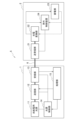
- FIG. 1 is a diagram illustrating a system configuration of a processing system according to an embodiment of the present disclosure.
- FIG. 2 is a diagram for explaining a transmitting/receiving unit of a controlled node.
- FIG. 3 is a diagram illustrating the function of the processing unit.
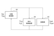
- FIG. 4 is a circuit diagram illustrating the electrical characteristics of the controlled node during charging.
- FIG. 5 is a circuit diagram illustrating the electrical characteristics of the controlled node during discharging.
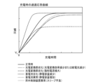
- FIG. 6 is a diagram for explaining transient response curves during charging in normal and faulty cases.
- FIG. 7 is a diagram for explaining transient response curves during discharge in normal and faulty conditions.
- FIG. 8 is a table showing the relationship between the transition of the voltage of the power storage unit and the cause of the failure.
- FIG. 8 is a table showing the relationship between the transition of the voltage of the power storage unit and the cause of the failure.
- FIG. 9 is a diagram illustrating a transient response curve during charging.
- FIG. 10 is a diagram for explaining a transient response curve during discharging.
- FIG. 11 is a sequence diagram illustrating a processing method according to an embodiment of the present disclosure.
- FIG. 12 is a diagram illustrating an example of a control node according to a modified example.
- FIG. 13 is a diagram illustrating the hardware configuration of a computer used in the control node.
- a processing system 5 includes a control node 1 and a controlled node 2.
- the control node 1 and the controlled node 2 are optical nodes.
- the control node 1 and the controlled node 2 are connected to each other by an optical fiber 6 so as to be able to communicate with each other.
- the controlled node 2 receives power supply light from the control node 1 via the optical fiber 6 and transmits and receives a control signal.
- the controlled node 2 stores power from the power supply light.
- the control signal may be transmitted from the control node 1 to the controlled node 2, for example, by being superimposed on the power supply light through intensity modulation.
- the controlled node 2 extracts the control signal intensity-modulated with the power supply light transmitted from the control node 1, and drives according to the control signal.
- the controlled node 2 may further intensity-modulate the power supply light with the control signal and transmit the control signal to the control node 1.
- control signal transmitted and received between the control node 1 and the controlled node 2 is transmitted and received by intensity modulation of the power supply light, but this is not limited to this.
- the control signal may also be transmitted and received by other existing methods, such as a WDM (Wavelength Division Multiplexing) transmission method using a light source other than the power supply light.
- WDM Widelength Division Multiplexing
- the controlled node 2 receives a request to acquire the amount of stored power in the controlled node 2 from the control node 1 as one of the control signals.
- the controlled node 2 also transmits the amount of stored power in the controlled node 2 to the control node 1 as one of the control signals.
- the controlled node 2 includes a transmitter/receiver 21, a photoelectric conversion unit 22, a power storage unit 23, and an external control device 24.
- the transmitter/receiver 21 transmits and receives power supply light and a control signal to and from the control node 1 via the optical fiber 6.
- the transmitter/receiver 21 may extract the control signal from the power supply light, or may intensity-modulate the power supply light with the control signal.
- the transmitter/receiver 21 receives the power supply light from the control node 1 via the optical fiber 6, and inputs the power supply light to the photoelectric conversion unit 22.
- the transmitter/receiver 21 receives a control signal, and inputs it to the off-site control device 24.
- the transmitter/receiver 21 intensity-modulates the power supply light with the control signal input from the off-site control device 24, and inputs the emphasized modulated power supply light to the control node 1.
- the transmitter/receiver 21 includes, for example, a first optical branching unit 211, a second optical branching unit 212, an optical circulator 213, an optical receiver 214, and an optical modulator 215.
- the first optical branching unit 211 branches the power supply light received via the optical fiber 6 into two. The branched light in one direction is received by the photoelectric conversion unit 22.
- the branched light in the other direction is received by the second optical branching unit 212 via the optical circulator 213.
- the second optical branching unit 212 branches the received power supply light into two.
- the branched light in one direction is received by the optical receiving unit 214 as a downstream communication optical signal.
- the optical receiving unit 214 extracts an intensity-modulated control signal from the received optical signal.
- the branched light in the other direction is intensity-modulated by the optical modulation unit 215 as upstream communication light.
- the communication light with the intensity-modulated control signal is transmitted to the control node 1 via the optical circulator 213, the first optical branching unit 211, and the optical fiber 6.
- the example shown in FIG. 2 is just one example.
- the transmitter/receiver unit 21 may have the configuration shown in Non-Patent Document 1.
- the photoelectric conversion unit 22 converts the power supply light received by the transmission/reception unit 21 into electricity.
- the photoelectric conversion unit 22 is, for example, a photodiode.
- the photoelectric conversion unit 22 stores the converted electricity in the power storage unit 23.
- the power storage unit 23 stores the power converted by the photoelectric conversion unit 22.
- the power storage unit 23 is, for example, a capacitor.
- the power storage unit 23 is in a charging period while power supply light is supplied from the control node 1 and is converted into electricity by the photoelectric conversion unit 22.
- the power storage unit 23 is in a discharging period during which it supplies power to the off-site control device 24 and the like while power supply light is not supplied from the control node 1.
- the off-site control device 24 is driven by the power stored in the power storage unit 23.
- the off-site control device 24 operates according to the control signal transmitted from the control node 1.
- the off-site control device 24 generates the control signal to be transmitted to the control node 1.
- the off-site control device 24 acquires the amount of stored power in the power storage unit 23 according to a control signal transmitted from the control node 1.
- the off-site control device 24 generates a control signal specifying the acquired amount of stored power.
- the amount of stored power in the power storage unit 23 may be the voltage of the power storage unit 23.
- the off-site control device 24 measures the voltage of the power storage unit 23 and generates a control signal including the measured voltage.
- the transceiver unit 21 transmits power supply light that has been intensity modulated by the generated control signal to the control node 1.
- the control node 1 includes an optical power supply light source 11, a transmitter 12, a receiver 13, a light source controller 14, and a processor 15.
- control node 1 may be implemented in a general computer.
- processing unit 15 of the control node 1 may be implemented in a general computer, and the other functions may be implemented in an optical node.
- the optical power supply light source (light source) 11 emits power supply light for optical power supply.
- the transmitter 12 transmits power supply light to the controlled node 2.
- the transmitter 12 transmits power supply light that is intensity modulated by the control signal generated in the processor 15.
- the receiver 13 receives the power supply light from the controlled node 2.
- the receiver 13 extracts a control signal from the power supply light that has been intensity modulated at the controlled node 2, and inputs the extracted control signal to the processor 15.
- the transmitter 12 and receiver 13 may be collectively referred to as a transceiver.
- the transceiver transmits and receives power supply light to and from the controlled node 2.
- the light source control unit 14 controls the on/off of the optical power supply light source 11 according to instructions from the processing unit 15.
- the processing unit 15 of the control node 1 will be described with reference to Figure 3.
- the processing unit 15 includes the stored power amount data 101, the physical property data 102, and the estimated stored power amount data 103, and the functions of an acquisition unit 121, an estimation unit 122, an identification unit 123, and a control unit 124.
- Each piece of data is stored in a storage device such as a memory 902 or a storage 903.
- Each function is implemented in the CPU 901.
- the stored power amount data 101 is data on the amount of stored power in the controlled node 2.
- the stored power amount data 101 may be data that associates a previously acquired amount of stored power with the time at which the amount of stored power was measured.
- the stored power amount data 101 may associate the identifier of the controlled node 2 with the amount of stored power.
- the physical characteristic data 102 is data that specifies the physical characteristics of the controlled node 2. Although the physical characteristics may change depending on the condition of the controlled node 2, such as deterioration, the physical characteristic data 102 includes at least the most recent physical characteristic data.
- the control node 1 manages the amount of stored power of multiple controlled nodes 2, the amount of stored power data 101 may correspond to the identifier of the controlled node 2 and the physical characteristic.
- the physical property data 102 is data that specifies the physical property of each parameter that affects the amount of stored power in the power storage unit 23 in the controlled node 2.
- the physical property data 102 includes the physical property of each parameter that affects the amount of stored power during charging, and the physical property of each device that affects the amount of stored power during discharging.
- the physical characteristics of each parameter are values of the specifications of each device, such as the optical power supply light source 11, the photoelectric conversion unit 22, the power storage unit 23, and the off-site control device 24.
- Each parameter may change due to deterioration, etc.
- the physical characteristics of the photoelectric conversion unit 22 are the emission light intensity of the optical power supply light source 11, the photon-electron conversion efficiency ( ⁇ ) of the photodiode that is the photoelectric conversion unit 22, and the saturation reverse current (J 0 ).
- the physical characteristic of the power storage unit 23 is the capacitance (C) of the capacitor that is the power storage unit 23.
- the physical characteristic of the off-site control device 24 is the current consumption (I LIC ) when not in operation.
- the estimated power storage data 103 is data that specifies the power storage amount of the controlled node 2 estimated by the estimation unit 122.
- the estimated power storage data 103 is a power storage amount estimated from each physical characteristic stored in the physical characteristic data 102.
- the acquisition unit 121 acquires the amount of stored power from the power supply light received from the controlled node 2.
- the receiving unit 13 inputs the control signal extracted from the power supply light received from the controlled node 2 to the acquisition unit 121.
- the acquisition unit 121 acquires the amount of stored power from the control signal.
- the acquisition unit 121 stores the amount of stored power in the stored power amount data 101.
- the acquisition unit 121 may associate the amount of stored power acquired from the controlled node 2 with a flag indicating whether it is charging or discharging. When the optical power supply light source 11 is on, the controlled node 2 is charging, and when it is off, it is discharging. The acquisition unit 121 associates the on/off state of the optical power supply light source 11 with the amount of stored power acquired from the controlled node 2, and stores the result in the stored power amount data 101.
- the estimation unit 122 estimates the amount of stored power from the physical characteristics of each parameter that affects the amount of stored power.
- the estimation unit 122 acquires the values of the emission light intensity of the optical power supply light source 11, the photon-electron conversion efficiency ( ⁇ ) of the photodiode that is the photoelectric conversion unit 22, and the saturation reverse current (J 0 ) from the physical characteristic data 102.
- the estimation unit 122 estimates the amount of stored power from the electrical characteristics of the amount of stored power in the power storage unit 23 and each value acquired from the physical characteristic data 102.
- the identifying unit 123 identifies the parameter whose physical property has changed and the physical property after the parameter has changed from the transition of the stored power amount.
- the existence of a difference may mean that there is a difference of a predetermined value or more.
- the identifying unit 123 calculates each value of the photon-electron conversion efficiency ( ⁇ ) and the saturation reverse current (J 0 ) of the photodiode which is the photoelectric conversion unit 22 from the transition of the stored power amount acquired from the controlled node 2 and the electrical property of the stored power amount in the power storage unit 23.
- the identifying unit 123 compares each calculated value with each value stored in advance in the physical property data 102 to identify the parameter whose physical property has changed and the value of the physical property after the parameter has changed.
- the determination unit 123 calculates the values of the slope during charging, the saturation voltage, and the slope during discharging from the change in the amount of stored power. From the calculated values, the determination unit 123 determines the parameter whose physical property has changed and the physical property after the parameter change. The determination unit 123 updates the physical property data 102 with the physical property after the parameter change. The estimation unit 122 thereby estimates the amount of stored power by referring to the physical property after the change.
- the control unit 124 controls the on/off of the optical power supply light source 11 by referring to the amount of stored power estimated by the estimation unit 122.
- the control unit 124 controls the on/off of the optical power supply light source 11 via the light source control unit 14, and performs control so that the amount of stored power in the controlled node 2 is kept within a predetermined range.
- the estimation unit 122 can estimate the amount of stored power using the current physical characteristics of each parameter estimated from the amount of stored power acquired in the controlled node 2. For example, even if a parameter in the controlled node 2 has deteriorated, the identification unit 123 can identify the physical characteristics after the deterioration, so the estimation unit 122 can accurately estimate the amount of stored power.
- the control unit 124 controls the on/off of the optical power supply light source 11 by referring to the amount of stored power estimated by the estimation unit 122, thereby allowing the amount of stored power in the controlled node 2 to be kept within a predetermined range with high accuracy.
- the control unit 124 may also refer to the amount of stored power estimated by the estimation unit 122 and generate a control signal including an instruction for the external control device 24 of the controlled node 2 to acquire the amount of stored power.
- the transceiver unit of the control node 1 transmits to the controlled node 2 a power supply light whose intensity has been modulated by the generated control signal.
- the external control device 24 of the controlled node 2 acquires the amount of stored power in the power storage unit 23 according to the control signal received from the control node 1 and transmits it to the control node 1.
- the control unit 124 knows that the estimation unit 122 is able to grasp the current state of the power storage unit 23 and is able to accurately estimate the amount of stored power. In such a case, the control unit 124 reduces the frequency with which it queries the controlled node 2 about the amount of stored power. This makes it possible to suppress power consumption in the controlled node 2.
- the consumption current ILIC is considered to be constant.
- the output current of the photoelectric conversion unit 22 is IPD
- the output voltage is VPD
- the input current of the power storage unit 23 is ICAP
- the voltage across both ends is VCAP
- the consumption current of the off-site control device 24 is ILIC
- the applied voltage is VLIC .
- equation (3) holds while the controlled node 2 is being charged.
- Equation (4) holds true based on the electrical characteristics of the capacitor that is the storage unit 23.
- Equation (6) holds true from equation (4) and equation (5).
- Figure 6 shows the change in voltage over time during charging.
- the transient response curve shown in Figure 6 is calculated from equation (4).
- Figure 7 shows the change in voltage over time during discharging.
- the transient response curve shown in Figure 6 is calculated from equation (6).
- the estimation unit 122 can estimate the change in voltage over time in the power storage unit 23, specifically the amount of power stored in the power storage unit 23, from the amount of power stored at the time the amount of power stored was last measured, the time spent charging and discharging after the last measurement, and equations (4) and (6).
- each of FIG. 6 and FIG. 7 includes a transient response curve when each parameter is deteriorated.
- the deteriorated transient response curve is calculated by deteriorating the physical characteristics of each parameter at a predetermined rate compared to the normal state.
- the saturation current of the photodiode which is the photoelectric conversion unit 22, is represented by J 0.
- the transient response curve when the saturation current increases due to deterioration is obtained by substituting the value of the saturation current when it is new at a predetermined rate into J 0 in the formula (4).
- the transient response curves when the other parameters are deteriorated are calculated in the same manner.
- the cause of the fault i.e., the changed parameters
- Figure 8 shows a table that correlates the change in the voltage of the power storage unit 23 obtained from the controlled node 2 with the cause of the fault. Note that the magnitude in Figure 8 is determined by comparison with the slope m or saturation voltage under normal conditions.
- FIG. 8 indicates that an abnormality has occurred in the off-site control device 24 due to a sleep failure.
- FIG. 8 indicates that the photoelectric conversion unit 22 has deteriorated or the amount of light supplied has decreased.
- FIG. 8 indicates that the storage battery has deteriorated and the capacitance has increased.
- FIG. 9 indicates that the saturation current of the photoelectric conversion unit 22 has increased.
- the slope during charging or discharging is shown in comparison with normal conditions, but this is not limited to this.
- the cause of failure may be identified by separating events into cases where the slope is larger or smaller than a threshold value for detecting degradation.
- the identification unit 123 calculates the values of the slope during charging, the saturation voltage, and the slope and saturation voltage during discharging from the transition of the amount of stored power.
- the identification unit 123 can compare the calculated values of the slope during charging, the slope during discharging, and the saturation voltage during charging when the physical characteristics of each parameter of the controlled node 2 have changed, using data such as those shown in Figures 6 to 8, to identify the parameters whose physical characteristics have changed.
- the slope of the voltage during charging is calculated from the voltage values at two times before the inflection point, such as tp /2 or tp /3.
- the saturation voltage can be calculated from the voltage at a time after the inflection point, such as 2tp or 3tp .
- the specification unit 123 substitutes the calculated slope into the coefficient of t on the right side of equation (8), and substitutes the calculated saturation voltage into the right side of equation (9).
- the method for calculating the slope during charging and the saturation voltage will be described with reference to FIG. 10.
- the slope during discharging is calculated from the voltage values at any two times.
- the determination unit 123 substitutes the calculated voltage values for the coefficient of t on the right-hand side of equation (6).
- the identification unit 123 can identify the current physical property values of each parameter. Furthermore, by comparing the physical property values of each parameter stored in the physical property data 102 with the calculated physical property values, the identification unit 123 can identify parameters whose physical properties have changed and the physical properties of the parameters after the change.
- the identification unit 123 calculates the value of the degraded parameter, it stores the calculated value in the physical property data 102.
- the estimation unit 122 can estimate a voltage value by referring to the value of the degraded parameter in the physical property data 102.
- the estimation unit 122 can calculate the amount of stored power in the power storage unit 23, taking into account the degradation in the controlled node 2.
- step S1 the control node 1 transmits a control signal including an instruction to measure the amount of stored power to the controlled node 2 via the optical fiber 6.
- the controlled node 2 acquires the amount of stored power in the power storage unit 23 according to the instruction acquired from the control node 1.
- step S2 the controlled node 2 transmits a control signal including the acquired amount of stored power to the control node 1 via the optical fiber 6.
- the control node 1 stores the amount of stored power acquired from the controlled node 2 in the stored power amount data 101.
- step S3 the control node 1 estimates the amount of stored power in the controlled node 2 by referring to the pre-stored physical property data 102.
- step S4 the control node 1 determines whether there is a difference of a predetermined value or more between the amount of stored power acquired in step S2 and the amount of stored power predicted in step S3, or whether there is no difference at all. If there is no difference, the process ends.
- step S5 the control node 1 identifies the changed parameters and the physical characteristics after the change.
- step S6 the control node 1 predicts the amount of stored power from the physical characteristics after the change.
- step S7 the control node 1 determines the frequency of turning on and off the optical power supply light source 11 and issuing instructions to measure the amount of stored power from the predicted amount of stored power. In accordance with the determined frequency, the control node 1 controls the on and off of the optical power supply light source 11 and sends instructions to the controlled node 2 to measure the amount of stored power.
- the control node 1a shown in FIG. 12 includes an optical switch 16 in the optical power supply light source 11. Note that in the example shown in FIG. 12, the control node 1a includes the optical switch 16, but this is not limiting.
- the control node 1a may include an optical coupler instead of the optical switch 16.
- the optical switch 16 has four terminals. Terminal A is connected to the optical power supply light source 11. Terminal B is connected to the controlled node 2 via the optical fiber 6. Terminal C is connected to the optical fiber loss meter 17. The optical fiber loss meter 17 measures the loss of the optical fiber 6 from the control node 1a to the controlled node 2. Terminal D is connected to the optical power meter 18. The optical power meter 18 measures the optical power of the power supply light output from the light source 11. The optical switch 16 can connect terminal A to any of terminals B to D. Terminal B can also be connected to any of terminals A to C. The operation of the optical switch 16 may be controlled by a computer or the like, or may be performed by an operator. The control node 1 is located in a place that is easy for operators to reach, such as a communications building, so the burden on the operator when operating the optical switch 16 is limited.
- the control node 1a When terminal A is connected to terminal B, the control node 1a can transmit power supply light to the controlled node 2.
- the optical fiber loss meter 17 When terminal B is connected to terminal C, the optical fiber loss meter 17 can measure the loss in the optical fiber 6.
- the optical power meter 18 When terminal A is connected to terminal D, the optical power meter 18 can measure the optical power of the optical power supply light source 11.
- the control node 1 may store the measurement values of the optical fiber loss meter 17 and the optical power meter 18 in the physical characteristic data 102 as parameters that affect the amount of stored power.
- the identification unit 123 may also refer to the measured loss and optical power of the optical fiber 6 to identify the parameter whose physical characteristic has changed.
- the control node 1a controls the optical switch 16 to measure the loss in the optical fiber 6 and the optical power of the power supply light. If the optical fiber loss and optical power do not change, it is assumed that the photoelectric conversion efficiency of the photodiode in the photoelectric conversion unit 22 has decreased. Also, if the optical fiber loss increases or the value of the optical power meter 18 decreases, the intensity of the power supply light incident on the photodiode in the photoelectric conversion unit 22 has decreased; in other words, the photodiode is considered to be normal.
- the cause of the failure can be further isolated by also measuring the physical measurements of the power supply light and the optical fiber 6.
- the processing system 5 retains physical characteristics that affect the voltage value of the power storage unit 23 in the controlled node 2, and is therefore able to predict the voltage value of the power storage unit 23 without constantly monitoring the voltage value.
- This allows the control node 1 to predict the amount of stored power in the controlled node 2 without having to inquire about the amount of stored power from the controlled node 2 each time the control node 1 refers to the amount of stored power in the controlled node 2.
- This reduces the frequency with which the controlled node 2 notifies the control node 1 of the amount of stored power, and allows the processing system 5 to achieve low power consumption.
- the control node 1 intermittently acquires the voltage value of the storage unit 23, and if there is a deviation from the predicted value, it is assumed that the parameters related to the storage unit 23 have changed due to degradation, etc. Even in such a case, the control node 1 can isolate the cause of the failure from the electrical characteristics related to the storage unit 23 and identify the changed parameters and the values of the physical characteristics after the change.
- control node 1 can accurately grasp the amount of stored power in the power storage unit 23 in the controlled node 2. Furthermore, even if the parameters that affect the amount of stored power in the power storage unit 23, specifically the optical power supply light source 11, the photoelectric conversion unit 22, the power storage unit 23, and the off-site control device 24, deteriorate, the control node 1 can grasp the amount of change in each physical characteristic of each device in chronological order. By grasping the change in the physical characteristic of each device, the processing system 5 can prevent device failure.
- the control node 1 can accurately grasp the amount of stored power in the controlled node 2 from a remote location. Compared to a case where an operator goes to the site to check the amount of stored power, the processing system 5 according to the present disclosure enables advanced operation at low cost.
- the control node 1 of the present disclosure described above is, for example, a general-purpose computer system including a CPU (Central Processing Unit, processor) 901, memory 902, storage 903 (HDD: Hard Disk Drive, SSD: Solid State Drive), communication device 904, input device 905, and output device 906.
- CPU Central Processing Unit
- memory 902 memory 902
- storage 903 Hard Disk Drive
- SSD Solid State Drive
- communication device 904 input device 905, and output device 906.
- each function of the control node 1 is realized by the CPU 901 executing a program loaded on the memory 902.
- the control node 1 may be implemented as one computer, or may be implemented as multiple computers.
- the control node 1 may also be a virtual machine implemented in a computer.
- the program of the control node 1 can be stored on a computer-readable recording medium such as a HDD, SSD, Universal Serial Bus (USB) memory, Compact Disc (CD), or Digital Versatile Disc (DVD), or can be distributed via a network.
- a computer-readable recording medium such as a HDD, SSD, Universal Serial Bus (USB) memory, Compact Disc (CD), or Digital Versatile Disc (DVD), or can be distributed via a network.
- the computer-readable recording medium is, for example, a non-transitory recording medium.
Landscapes
- Engineering & Computer Science (AREA)
- Physics & Mathematics (AREA)
- Computer Networks & Wireless Communication (AREA)
- Electromagnetism (AREA)
- Signal Processing (AREA)
- Optics & Photonics (AREA)
- Power Engineering (AREA)
- Optical Communication System (AREA)
Priority Applications (2)
| Application Number | Priority Date | Filing Date | Title |
|---|---|---|---|
| JP2025523149A JPWO2024247199A1 (https=) | 2023-05-31 | 2023-05-31 | |
| PCT/JP2023/020377 WO2024247199A1 (ja) | 2023-05-31 | 2023-05-31 | 処理システム、処理方法および制御ノード |
Applications Claiming Priority (1)
| Application Number | Priority Date | Filing Date | Title |
|---|---|---|---|
| PCT/JP2023/020377 WO2024247199A1 (ja) | 2023-05-31 | 2023-05-31 | 処理システム、処理方法および制御ノード |
Publications (1)
| Publication Number | Publication Date |
|---|---|
| WO2024247199A1 true WO2024247199A1 (ja) | 2024-12-05 |
Family
ID=93657319
Family Applications (1)
| Application Number | Title | Priority Date | Filing Date |
|---|---|---|---|
| PCT/JP2023/020377 Ceased WO2024247199A1 (ja) | 2023-05-31 | 2023-05-31 | 処理システム、処理方法および制御ノード |
Country Status (2)
| Country | Link |
|---|---|
| JP (1) | JPWO2024247199A1 (https=) |
| WO (1) | WO2024247199A1 (https=) |
Citations (3)
| Publication number | Priority date | Publication date | Assignee | Title |
|---|---|---|---|---|
| JP2001025180A (ja) * | 1999-07-06 | 2001-01-26 | Nippon Telegr & Teleph Corp <Ntt> | 光パワー給電装置 |
| JP2021019441A (ja) * | 2019-07-22 | 2021-02-15 | 京セラ株式会社 | 光ファイバー給電システム |
| WO2023047479A1 (ja) * | 2021-09-22 | 2023-03-30 | 三菱電機株式会社 | 親局側通信装置、子局側通信装置、および、光通信システム |
-
2023
- 2023-05-31 JP JP2025523149A patent/JPWO2024247199A1/ja active Pending
- 2023-05-31 WO PCT/JP2023/020377 patent/WO2024247199A1/ja not_active Ceased
Patent Citations (3)
| Publication number | Priority date | Publication date | Assignee | Title |
|---|---|---|---|---|
| JP2001025180A (ja) * | 1999-07-06 | 2001-01-26 | Nippon Telegr & Teleph Corp <Ntt> | 光パワー給電装置 |
| JP2021019441A (ja) * | 2019-07-22 | 2021-02-15 | 京セラ株式会社 | 光ファイバー給電システム |
| WO2023047479A1 (ja) * | 2021-09-22 | 2023-03-30 | 三菱電機株式会社 | 親局側通信装置、子局側通信装置、および、光通信システム |
Also Published As
| Publication number | Publication date |
|---|---|
| JPWO2024247199A1 (https=) | 2024-12-05 |
Similar Documents
| Publication | Publication Date | Title |
|---|---|---|
| US11029354B1 (en) | Systems and methods for distributed sensing of a powerline conductor | |
| JP7666835B2 (ja) | 高損失ループバック(hllb)データを用いた光伝送システムにおける要素のパラメータ報告のための技術及びそれを実施するラインモニタリングシステム | |
| KR101095976B1 (ko) | 전력선통신을 이용한 배전선로의 분기선 진단 시스템 | |
| WO2019178285A1 (en) | Power compensator for cellular communication base station | |
| JP6998164B2 (ja) | 光給電システム | |
| CN113839712B (zh) | 基于光模块的信号传输监测方法、设备、存储介质及装置 | |
| CN110649962A (zh) | 一种智能光缆在线监测系统及监测方法 | |
| US20210083792A1 (en) | Optical Device and Hub Node for an Optical Network | |
| US9414448B2 (en) | Stability of an optical source in an optical network test instrument | |
| CN102013925A (zh) | 光纤网络终端装置及其操作方法 | |
| WO2024247199A1 (ja) | 処理システム、処理方法および制御ノード | |
| CN110048767A (zh) | 光缆接续盒及其监测方法 | |
| CN101958749A (zh) | 一种光缆在线监测的方法 | |
| EP3178174B1 (en) | Distributed raman amplifier systems | |
| US11888513B2 (en) | Optronic transceiver module with integrated protection | |
| KR102421563B1 (ko) | Opgw관리 시스템 및 방법 | |
| JP6706998B2 (ja) | 加入者線終端装置、制御方法及び光通信システム | |
| JP7795139B2 (ja) | 判定装置、及び、判定方法 | |
| US20120237215A1 (en) | Terrestrial optical fiber communication with added capacity | |
| JP5938358B2 (ja) | 光モジュール寿命予測システム、光モジュール寿命予測装置、光モジュール寿命予測方法及び光モジュール寿命予測プログラム | |
| CN205620458U (zh) | 串补测量系统 | |
| JP6689162B2 (ja) | 加入者線終端装置及び制御方法 | |
| CN108872874A (zh) | 一种光端机备用电源的检测方法及装置 | |
| KR102535594B1 (ko) | 기계학습 기반 가입자 광단말기 상태 파악 장치 및 그 방법 | |
| KR20210016805A (ko) | 무정전 전원 관리 장치 |
Legal Events
| Date | Code | Title | Description |
|---|---|---|---|
| 121 | Ep: the epo has been informed by wipo that ep was designated in this application |
Ref document number: 23939674 Country of ref document: EP Kind code of ref document: A1 |
|
| ENP | Entry into the national phase |
Ref document number: 2025523149 Country of ref document: JP Kind code of ref document: A |
|
| NENP | Non-entry into the national phase |
Ref country code: DE |