WO2024247147A1 - 液体濾過装置の制御装置及び加工システム - Google Patents
液体濾過装置の制御装置及び加工システム Download PDFInfo
- Publication number
- WO2024247147A1 WO2024247147A1 PCT/JP2023/020210 JP2023020210W WO2024247147A1 WO 2024247147 A1 WO2024247147 A1 WO 2024247147A1 JP 2023020210 W JP2023020210 W JP 2023020210W WO 2024247147 A1 WO2024247147 A1 WO 2024247147A1
- Authority
- WO
- WIPO (PCT)
- Prior art keywords
- liquid
- control device
- unit
- pressure value
- machining
- Prior art date
- Legal status (The legal status is an assumption and is not a legal conclusion. Google has not performed a legal analysis and makes no representation as to the accuracy of the status listed.)
- Ceased
Links
Images




Classifications
-
- B—PERFORMING OPERATIONS; TRANSPORTING
- B23—MACHINE TOOLS; METAL-WORKING NOT OTHERWISE PROVIDED FOR
- B23H—WORKING OF METAL BY THE ACTION OF A HIGH CONCENTRATION OF ELECTRIC CURRENT ON A WORKPIECE USING AN ELECTRODE WHICH TAKES THE PLACE OF A TOOL; SUCH WORKING COMBINED WITH OTHER FORMS OF WORKING OF METAL
- B23H1/00—Electrical discharge machining, i.e. removing metal with a series of rapidly recurring electrical discharges between an electrode and a workpiece in the presence of a fluid dielectric
- B23H1/10—Supply or regeneration of working media
Definitions
- This disclosure relates to a control device and processing system for a liquid filtration device.
- JP 2021-167052 A discloses an electric discharge machine equipped with a waste liquid tank, a filter, and a clean liquid tank.
- the waste liquid tank stores machining fluid containing machining waste.
- the machining fluid stored in the waste liquid tank is sent to the clean liquid tank via the filter.
- the filter filters the machining fluid.
- Filters have a lifespan (product lifespan). There is a need for a control device and processing system for liquid filtration devices that can extend the lifespan of filters.
- An aspect of the present disclosure is a control device for a liquid filtration device having a wastewater tank for storing wastewater, which is a liquid containing metal scraps generated by processing a metal workpiece with a processing machine, a filter for filtering the wastewater, and a clean liquid tank for storing clean liquid, which is the liquid that has passed through the filter, and the control device includes a memory unit for storing model waveform data indicating changes in pressure value applied to the filter relative to the cumulative processing amount of the processing machine, an estimation unit for estimating the cumulative processing amount, an acquisition unit for acquiring the pressure value detected by a pressure sensor, and a mechanism control unit for controlling a resistivity adjustment mechanism using the acquired pressure value, the estimated cumulative processing amount, and the model waveform to adjust the resistivity value of the liquid.
- Another aspect of the present disclosure is a processing system including a control device for the liquid filtration device, the liquid filtration device, and the processing machine.
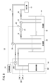
- FIG. 1 is a schematic diagram of a processing system.
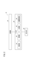
- FIG. 2 is a schematic diagram of the control device.
- FIG. 3 is a graph for explaining the comparison unit.
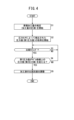
- FIG. 4 is a flowchart showing the procedure of the mechanism control process of the control device.
- FIG. 5 is a schematic diagram of a control device according to the first modified example.
- FIG. 6 is a schematic diagram of a control device according to the second modification.
- FIG. 7 is a diagram for explaining the accumulated machining amount.
- FIG. 8 is a schematic diagram of a machining system according to the fourth modification.
- the machining fluid used in processing machines contains metal chips generated during the machining of metal workpieces.
- the filter becomes clogged with the metal chips, the operator must replace the filter. After use, the filter is usually discarded without being reused. To reduce the number of times the filter needs to be replaced and the amount of discarded filters, there was a need to extend the filter's lifespan.
- the inventors have found that lowering the resistivity of the machining fluid extends the filter's lifespan compared to when the resistivity of the machining fluid is not lowered. However, it is not efficient to constantly perform a process to lower the resistivity of the machining fluid while machining a metal workpiece. Therefore, the timing of lowering the resistivity of the machining fluid became an issue.
- the objective of the disclosed technology is to provide a control device and processing system for a liquid filtration device that can efficiently extend the life of the filter.
- resistivity It is generally known that the reciprocal of resistivity [ ⁇ m] is electrical conductivity [S/m]. Therefore, the term "resistivity” can be replaced with the term “electrical conductivity”. When the term “resistivity” is replaced with the term “electrical conductivity”, “reducing resistivity” is replaced with “increasing electrical conductivity”. Conversely, “increasing resistivity” is replaced with "reducing electrical conductivity”.
- FIG. 1 is a schematic diagram of a machining system 10.
- the machining system 10 includes a machining machine 12, a liquid filtering device 14, and a control device 16.
- the machining machine 12 is a machine that processes a metal workpiece, which is a workpiece made of a metal material.
- the machining machine 12 may be an electric discharge machine that performs electric discharge machining on the metal workpiece in a machining fluid stored in a machining tank.
- the machining fluid is a liquid used for machining the metal workpiece.
- the liquid filtration device 14 has a waste liquid tank 18, a clean liquid tank 20, a first pump 22, a filter 24, a second pump 26, and a resistivity adjustment mechanism 28.
- the machining fluid used during machining by the machining machine 12 is discharged from the machining machine 12 through the drainage path 30 into the waste fluid tank 18.
- the machining fluid discharged from the machining machine 12 is contaminated with sludge.
- the sludge contains metal chips generated during the machining of metal workpieces.
- the machining fluid stored in the dirty fluid tank 18 is sent to the clean fluid tank 20 through the filtration path 32.
- a first pump 22 and a filter 24 are provided in the filtration path 32.
- the first pump 22 sucks up the machining fluid from the dirty fluid tank 18 and sends it to the clean fluid tank 20.
- the filter 24 filters the machining fluid sent from the dirty fluid tank 18 to the clean fluid tank 20, and removes sludge such as metal chips from the machining fluid.
- the machining fluid stored in the clean fluid tank 20 is sent from the clean fluid tank 20 through a supply path 34 to the processing machine 12.
- a second pump 26 is provided in the supply path 34. The second pump 26 sucks up the machining fluid from the clean fluid tank 20 and sends it to the processing machine 12.
- the resistivity adjustment mechanism 28 is a mechanism for adjusting the resistivity of the machining fluid.
- the resistivity adjustment mechanism 28 reduces the resistivity of the machining fluid by supplying a chemical that reduces the resistivity to the machining fluid.
- Non-purified water may be used instead of the chemical that reduces the resistivity.
- Non-purified water is water that has not been purified and does not include pure water. Pure water contains almost no ions that contribute to a reduction in the resistivity of the machining fluid, and therefore cannot reduce the resistivity of the machining fluid.
- non-purified water contains a relatively large number of ions that contribute to a reduction in the resistivity of the machining fluid, and therefore can reduce the resistivity of the machining fluid.
- Examples of non-purified water include tap water and industrial water. In other words, examples of non-purified water include clean water and grey water. Well water may be used as non-purified water.
- the resistivity adjustment mechanism 28 may be composed of a supply unit 28A that supplies chemicals or non-purified water, a communication path 28B that connects the supply unit 28A with the clean liquid tank 20, and a valve 28C provided on the communication path 28B. In this case, when the valve 28C opens, the chemicals or non-purified water is supplied from the supply unit 28A to the clean liquid tank 20 via the communication path 28B. This reduces the resistivity value of the processing liquid stored in the clean liquid tank 20.
- FIG. 2 is a schematic diagram of the control device 16.
- the control device 16 is a device that controls the resistivity adjustment mechanism 28.
- the control device 16 may be incorporated into a numerical control device that controls the processing machine 12.
- the control device 16 has one or more processors 50, such as a CPU or MPU, and one or more storage units 52, such as a ROM, RAM, or hard disk.
- the control device 16 causes the processor 50 to execute a mechanism control program stored in the storage unit 52.
- the mechanism control program is a program for controlling the resistivity adjustment mechanism 28.
- the processor 50 When the mechanism control program is executed, the processor 50 operates as an estimation unit 54, an acquisition unit 56, a comparison unit 58, and a mechanism control unit 60. At least one of the estimation unit 54, the acquisition unit 56, the comparison unit 58, and the mechanism control unit 60 may be realized by an integrated circuit such as an ASIC or an FPGA. Also, at least one of the estimation unit 54, the acquisition unit 56, the comparison unit 58, and the mechanism control unit 60 may be configured by an electronic circuit including a discrete device.
- a pressure sensor 62 is connected to the control device 16.
- the pressure sensor 62 is a sensor that detects the pressure value applied to the filter 24.
- the pressure sensor 62 is installed upstream of the filter 24.
- the upstream of the filter 24 is upstream from the perspective of the liquid flowing through the filtration path 32.
- the pressure sensor 62 is installed in the filtration path 32 between the first pump 22 and the filter 24 (see Figure 1).
- the estimation unit 54 estimates the accumulated processing amount of the processing machine 12.
- the estimation unit 54 measures the processing amount from a predetermined accumulation start point to a predetermined accumulation end point. As a result, as the processing amount increases, the measured parameter increases. This parameter is information that indicates the processing amount. When the predetermined accumulation end point is reached, the estimation unit 54 ends the measurement of the processing amount and resets the parameter. In other words, the accumulated processing amount becomes zero.
- the accumulation start point is a point corresponding to the start of use of an unused filter 24.
- the accumulation start point may be the point at which an installation sensor detects that the filter 24 has been attached.
- the accumulation start point may be the point at which the user specifies the start of accumulation of the processing amount.
- the accumulation end point is a point at which the accumulation end occurs when the product life of the filter 24 has expired.
- the accumulation end point may be the point at which an installation sensor detects that the filter 24 has been removed.
- the accumulation end point may be the point at which the user specifies the end of accumulation of the processing amount.
- the cumulative processing amount is the cumulative time spent processing by the processing machine 12.
- the estimation unit 54 can obtain the cumulative time spent processing by the processing machine 12 from the accumulation start point to the accumulation end point by measuring the execution time of the processing program by the processing machine 12.
- the processing load on the processor 50 can be reduced compared to when the cumulative processing amount is calculated from the processing speed of the processing machine 12, etc.
- the acquisition unit 56 acquires pressure data at a predetermined sampling period and stores the acquired pressure data in the memory unit 52.
- the pressure data indicates at least the pressure value detected by the pressure sensor 62 and the detection time.
- the comparison unit 58 compares the pressure value acquired by the acquisition unit 56 with the value indicated by the data pre-stored in the memory unit 52. In other words, the comparison unit 58 compares whether the pressure value acquired by the comparison unit 58 is higher than an expected pressure value. Details of the comparison unit 58 and the data pre-stored in the memory unit 52 will be described later.
- the mechanism control unit 60 controls the resistivity adjustment mechanism 28 based on the comparison result of the comparison unit 58. If the comparison result by the comparison unit 58 indicates that the pressure value acquired by the comparison unit 58 is higher than the expected pressure value, the mechanism control unit 60 causes the resistivity adjustment mechanism 28 to start adjusting the resistivity value of the machining fluid. If the resistivity adjustment mechanism 28 is composed of a supply unit 28A, a communication path 28B, and a valve 28C, the mechanism control unit 60 opens the valve 28C. This enables the resistivity adjustment mechanism 28 to adjust the resistivity value of the machining fluid. In other words, the resistivity value of the machining fluid can be lowered.
- the timing at which the mechanism control unit 60 causes the resistivity adjustment mechanism 28 to end the adjustment is not particularly limited. For example, when a predetermined time has elapsed since the mechanism control unit 60 caused the resistivity adjustment mechanism 28 to start the adjustment, the mechanism control unit 60 causes the resistivity adjustment mechanism 28 to end the adjustment. In the case where the resistivity adjustment mechanism 28 is composed of a supply unit 28A, a communication path 28B, and a valve 28C, the mechanism control unit 60 closes the valve 28C. This causes the resistivity adjustment mechanism 28 to end the adjustment of the resistivity value of the machining fluid.
- the comparison unit 58 uses model waveform MW data pre-stored in the memory unit 52.
- the model waveform MW data may be a plurality of sampling points on the model waveform MW, or may be a function capable of reproducing the model waveform MW.
- the model waveform MW indicates a model transition of the pressure value of the filter 24 relative to the cumulative processing volume of the processing machine 12.
- the comparison unit 58 compares the first pressure value P1 with the second pressure value P2.
- the first pressure value P1 is the pressure value acquired by the acquisition unit 56 from the pressure sensor 62.
- the second pressure value P2 is the pressure value on the model waveform MW at the cumulative processing amount estimated by the estimation unit 54 in response to the first pressure value P1.
- the "cumulative processing amount estimated by the estimation unit 54 in response to the first pressure value P1" is the cumulative processing amount estimated by the estimation unit 54 immediately prior to the latest pressure value acquired by the acquisition unit 56, but is not limited to this.
- the number of comparisons between the first pressure value P1 and the second pressure value P2 may be one or two or more. When the number of comparisons is two or more, the comparison unit 58 may periodically compare the first pressure value P1 and the second pressure value P2. Alternatively, the comparison unit 58 may compare the first pressure value P1 and the second pressure value P2 at the timing when the pressure value acquired by the acquisition unit 56 reaches each of a plurality of predetermined set values. Alternatively, the comparison unit 58 may compare the first pressure value P1 and the second pressure value P2 at the timing when the cumulative processing amount estimated by the estimation unit 54 reaches each of a plurality of predetermined set values.
- the mechanism control unit 60 controls the resistivity adjustment mechanism 28 to lower the resistivity value of the processing fluid.
- Figure 4 is a flow chart showing the procedure of the mechanism control process of the control device 16. Note that Figure 4 shows the procedure of the mechanism control process when the number of comparisons in the comparison unit 58 is two or more.
- step S1 the estimation unit 54 starts estimating the cumulative processing volume (measuring the processing volume) of the processing machine 12.
- the mechanism control process proceeds to step S2.
- step S2 the acquisition unit 56 starts acquiring the pressure value detected by the pressure sensor 62. Once acquisition of the pressure value starts, the mechanism control process proceeds to step S3.
- step S3 the comparison unit 58 determines whether it is time to compare. If it is not time to compare, the mechanism control process remains in step S3. On the other hand, if it is time to compare, the mechanism control process proceeds to step S4.
- step S4 the comparison unit 58 compares the first pressure value P1 with the second pressure value P2 (see FIG. 3). If the first pressure value P1 is equal to or less than the second pressure value P2, the mechanism control process returns to step S3. On the other hand, if the first pressure value P1 exceeds the second pressure value P2, the mechanism control process proceeds to step S5.
- step S5 the mechanism control unit 60 controls the resistivity adjustment mechanism 28 to lower the resistivity value of the machining fluid. Then, the mechanism control process ends.
- the mechanism control unit 60 adjusts the resistivity value of the machining fluid using the pressure value detected by the pressure sensor 62, the cumulative machining amount estimated by the estimation unit 54, and the model waveform MW stored in the memory unit 52. This makes it possible to obtain the timing for adjusting the resistivity value while capturing the ideal model waveform MW value and the actual measured value. As a result, the life of the filter 24 can be efficiently extended.
- a first pressure value P1 which is the pressure value detected by the pressure sensor 62
- a second pressure value P2 which is the pressure value on the model waveform MW at the cumulative machining amount estimated corresponding to the first pressure value P1.
- the control device 16 reduces the resistivity value of the machining fluid. This makes it possible to appropriately capture the timing for reducing the resistivity value of the machining fluid.
- (Variation 1) 5 is a schematic diagram of the control device 16 according to the first modification.
- the comparison unit 58 of the control device 16 is replaced with a comparison unit 58'.
- the comparison unit 58' compares the first accumulated machining amount MA1 with the second accumulated machining amount MA2 (see FIG. 3).
- the first accumulated machining amount MA1 is the accumulated machining amount estimated by the estimation unit 54.
- the second accumulated machining amount MA2 is the accumulated machining amount on the model waveform MW at the pressure value acquired by the acquisition unit 56 in response to the first accumulated machining amount MA1.
- the "pressure value acquired by the acquisition unit 56 in response to the first accumulated machining amount MA1" is the pressure value acquired by the acquisition unit 56 immediately prior to the latest accumulated machining amount estimated by the estimation unit 54, but is not limited to this.
- the number of comparisons between the first accumulated machining amount MA1 and the second accumulated machining amount MA2 may be one or more than two. When the number of comparisons is two or more, the comparison unit 58' may periodically compare the first accumulated machining amount MA1 and the second accumulated machining amount MA2. Alternatively, the comparison unit 58' may compare the first accumulated machining amount MA1 and the second accumulated machining amount MA2 at the timing when the pressure value acquired by the acquisition unit 56 reaches each of a plurality of predetermined set values. Alternatively, the comparison unit 58' may compare the first accumulated machining amount MA1 and the second accumulated machining amount MA2 at the timing when the accumulated machining amount estimated by the estimation unit 54 reaches each of a plurality of predetermined set values.
- the mechanism control unit 60 controls the resistivity adjustment mechanism 28 to lower the resistivity value of the machining fluid. This makes it possible to appropriately capture the timing for lowering the resistivity value of the machining fluid, similar to the above embodiment.
- (Variation 2) 6 is a schematic diagram of the control device 16 according to Modification 2.
- data of a plurality of model waveforms MW is stored in the storage unit 52.
- Each of the plurality of model waveforms MW is created corresponding to a different type of filter 24.
- control device 16 of the embodiment is newly equipped with an identification unit 64 and a selection unit 66.
- the processor 50 operates as the identification unit 64 and the selection unit 66.
- At least one of the identification unit 64 and the selection unit 66 may be realized by an integrated circuit, or may be configured by an electronic circuit including a discrete device.
- the identification unit 64 identifies the type of filter 24. For example, a first table that specifies the correspondence between the type of filter 24 and the code number is stored in the storage unit 52. In this case, the identification unit 64 can identify the type of filter 24 that corresponds to the code number supplied from an operation panel or the like in response to a user's input operation based on the first table. Note that, if the code number is defined in the machining program, the identification unit 64 can analyze the machining program to identify the type of filter 24.
- the selection unit 66 selects a model waveform MW corresponding to the type of filter 24 identified by the identification unit 64 from among the multiple model waveforms MW stored in the memory unit 52. For example, a second table that specifies the correspondence between the model waveform MW and the type of filter 24 is stored. In this case, the selection unit 66 can select a model waveform MW corresponding to the type of filter 24 identified by the identification unit 64 based on the second table.
- the comparison unit 58 (or the comparison unit 58') performs the above-mentioned comparison using the model waveform MW selected by the selection unit 66.
- the cumulative machining amount estimated by the estimation unit 54 may be calculated.
- the estimation unit 54 calculates the cumulative machining amount as a cumulative value obtained by multiplying the machining speed V of the machining machine 12, the thickness T of the metal workpiece WK, and the groove width W of the machined groove MG.
- the machining speed V of the machining machine 12 can be acquired from the machining program.
- the thickness T of the metal workpiece WK and the groove width W of the machined groove MG are specified by, for example, a user.
- the groove width W is a groove formed by electric discharge machining of the wire electrode E on the metal workpiece WK. In this modified example, the cumulative machining amount of the electric discharge machine can be appropriately estimated.
- (Variation 4) 8 is a schematic diagram of the processing system 10 according to Modification 4.
- the configuration of the resistivity adjustment mechanism 28 is different from that of the above embodiment.
- the resistivity adjustment mechanism 28 is composed of a chemical container 28E, a circulation path 28F, and a valve 28G.
- the chemical container 28E is a container that contains a chemical that reduces the resistivity of the machining fluid, and is connected to the circulation path 28F.
- the chemical container 28E uses the chemical to reduce the resistivity of the machining fluid sent from the clean fluid tank 20, and outputs the machining fluid with the reduced resistivity.
- the circulation path 28F includes an outward path 28F_1 and a return path 28F_2.
- the outward path 28F_1 connects the supply path 34 upstream of the second pump 26 to the chemical container 28E.
- the return path 28F_2 connects the chemical container 28E to the clean liquid tank 20.
- Valve 28G is provided on outward path 28F_1. When valve 28G is open, a portion of the machining fluid stored in clean fluid tank 20 circulates between clean fluid tank 20 and chemical container 28E. Valve 28G may also be provided on return path 28F_2.
- the resistivity adjustment mechanism 28 can also pass the processing fluid through a container that contains a chemical that reduces the resistivity value.
- the machining fluid whose resistivity is adjusted by the resistivity adjusting mechanism 28 is not limited to the clean fluid stored in the clean fluid tank 20.
- the resistivity adjusting mechanism 28 may adjust the resistivity of the waste fluid stored in the waste fluid tank 18. In this case, the same effect as in the above embodiment can be obtained.
- the control device 16 adjusts the resistivity of the machining fluid using the pressure value detected by the pressure sensor 62, the accumulated machining amount estimated by the estimating unit 54, and the model waveform MW stored in the memory unit 52. This makes it possible to obtain the timing of adjusting the resistivity while capturing the ideal model waveform MW value and the actual measured value. As a result, the life of the filter 24 can be efficiently extended.
- the lifespan of a processing machine filter when machining a metal workpiece that is an aluminum-based material is 10% to 25% of the lifespan of a processing machine filter when machining a metal workpiece that is an iron-based material. Therefore, when the metal workpiece is an aluminum-based material, lowering the resistivity of the processing fluid is particularly useful.
- the present disclosure relates to a control device (16) for a liquid filtration device (14) having a wasteful liquid tank (18) for storing wasteful liquid, which is a liquid containing metal scraps generated by the processing of a metal workpiece by a processing machine (12), a filter (24) for filtering the wasteful liquid, and a clean liquid tank (20) for storing clean liquid, which is the liquid that has passed through the filter,
- the control device (16) comprising: a memory unit (52) for storing data of a model waveform (MW) that indicates a change in pressure value applied to the filter relative to the cumulative processing amount of the processing machine; an estimation unit (54) for estimating the cumulative processing amount; an acquisition unit (56) for acquiring the pressure value detected by a pressure sensor (62); and a mechanism control unit (60) for controlling a resistivity adjustment mechanism (28) using the acquired pressure value, the estimated cumulative processing amount, and the model waveform to adjust the resistivity value of the liquid.
- MW model waveform
- a control device for a liquid filtration device as described in Appendix 1, comprising a comparison unit (58) that compares a first pressure value (P1), which is the pressure value acquired by the acquisition unit, with a second pressure value (P2), which is the pressure value on the model waveform at the accumulated processing amount estimated by the estimation unit in response to the first pressure value, and when the first pressure value exceeds the second pressure value, the mechanism control unit may adjust the resistivity value.
- P1 the pressure value acquired by the acquisition unit
- P2 which is the pressure value on the model waveform at the accumulated processing amount estimated by the estimation unit in response to the first pressure value
- a control device for a liquid filtration device as described in Appendix 1, comprising a comparison unit (58') that compares a first accumulated processing amount (MA1), which is the accumulated processing amount estimated by the estimation unit, with a second accumulated processing amount (MA2), which is the accumulated processing amount on the model waveform at the pressure value acquired by the acquisition unit corresponding to the first accumulated processing amount, and when the first accumulated processing amount is lower than the second accumulated processing amount, the mechanism control unit may adjust the resistivity value.
- MA1 a first accumulated processing amount
- MA2 the mechanism control unit
- a control device for a liquid filtration device as described in Appendix 2 or 3, comprising an identification unit (64) that identifies the type of filter, and a selection unit (66) that selects, from a plurality of model waveforms stored in the memory unit, the model waveform corresponding to the type of filter identified by the identification unit, and the comparison unit may use the model waveform selected by the selection unit.
- the resistivity adjustment mechanism may supply a chemical that reduces the resistivity value or non-purified water to the liquid, or may pass the liquid through a container containing a chemical that reduces the resistivity value.
- the accumulated processing amount may be an accumulated time for which the processing machine has processed.
- the cumulative machining amount may be a cumulative value obtained by multiplying the machining speed (V) of the machining machine that machines the metal workpiece, the thickness (T) of the metal workpiece, and the groove width (W) of a machined groove (MG) formed by electric discharge machining of a wire electrode (E) on the metal workpiece.
- the metal workpiece may be an aluminum-based material.
- the processing machine may be an electric discharge machine.
- the present disclosure is a processing system (10) including a control device for a liquid filtration device according to any one of appendices 1 to 9, the liquid filtration device, and the processing machine.
- Reference Signs List 10 10... Processing system 12... Processing machine 14... Liquid filtration device 16... Control device 18... Waste liquid tank 20... Clean liquid tank 24... Filter 28... Resistivity adjustment mechanism 50... Processor 52... Memory unit 54... Estimation unit 56... Acquisition unit 58... Comparison unit 60... Mechanism control unit 62... Pressure sensor 64... Identification unit 66... Selection unit
Landscapes
- Engineering & Computer Science (AREA)
- Mechanical Engineering (AREA)
- Electrical Discharge Machining, Electrochemical Machining, And Combined Machining (AREA)
Abstract
本開示は、汚液槽とフィルタと清液槽とを有する液体濾過装置の制御装置である。液体濾過装置の制御装置は、加工機の累積加工量に対するフィルタに加わる圧力値の変化を示すモデル波形のデータが記憶される記憶部と、累積加工量を推定する推定部と、圧力センサによって検出される圧力値を取得する取得部と、比抵抗調整機構を制御して、液体の比抵抗値を調整する機構制御部と、を備える。
Description
本開示は、液体濾過装置の制御装置及び加工システムに関する。
特開2021-167052号公報には、汚液槽と、フィルタと、清液槽とを備える放電加工機が開示されている。汚液槽には、加工屑を含む加工液が貯留される。汚液槽に貯留された加工液は、フィルタを介して清液槽に送られる。フィルタは、加工液を濾過する。
フィルタには寿命(製品寿命)が存在する。フィルタを長寿命化する液体濾過装置の制御装置及び加工システムが待望される。
本開示の態様は、加工機による金属ワークの加工で発生した金属屑を含む液体である汚液を貯留する汚液槽と、前記汚液を濾過するフィルタと、前記フィルタを通過した前記液体である清液を貯留する清液槽とを有する液体濾過装置の制御装置であって、前記加工機の累積加工量に対する前記フィルタに加わる圧力値の変化を示すモデル波形のデータが記憶される記憶部と、前記累積加工量を推定する推定部と、圧力センサによって検出される前記圧力値を取得する取得部と、取得された前記圧力値と、推定された前記累積加工量と、前記モデル波形とを用いて、比抵抗調整機構を制御して、前記液体の比抵抗値を調整する機構制御部と、を備える。
本開示の他の態様は、上記液体濾過装置の制御装置と、前記液体濾過装置と、前記加工機とを備える加工システムである。
加工機の加工に用いられる液体である加工液には、金属ワークの加工により発生する金属屑が混入する。この金属屑の付着によりフィルタの目が詰まると、オペレータはフィルタを交換する必要がある。使用後のフィルタは、通常、再利用されることなく廃棄される。フィルタの交換回数の低減、及び、フィルタの廃棄量の低減のため、フィルタの寿命を延ばすことが求められた。
本発明者らは、加工液の比抵抗値を下げると、当該加工液の比抵抗値を下げない場合に比べてフィルタの寿命が長くなることを見出した。しかし、金属ワークの加工中に常に加工液の比抵抗値を低下させる処理を行うことは効率的ではない。そのため、加工液の比抵抗値を下げるタイミングが問題となった。
本開示の技術は、効率よくフィルタの寿命を延ばし得る液体濾過装置の制御装置及び加工システムを提供することを課題とする。
本開示において、「比抵抗値」という用語がある。一般に、比抵抗値[Ωm]の逆数は電気伝導度[S/m]であることが知られている。したがって、「比抵抗値」という用語は、「電気伝導度」という用語に置換可能である。「比抵抗値」という用語が「電気伝導度」という用語に置換された場合、「比抵抗値を下げる」は、「電気伝導度を上げる」に置換される。逆に、「比抵抗値を上げる」は、「電気伝導度を下げる」に置換される。
[実施形態]
図1は、加工システム10の模式図である。加工システム10は、加工機12と、液体濾過装置14と、制御装置16とを有する。加工機12は、金属材料のワークである金属ワークを加工する機械である。加工機12は、加工槽に貯留される加工液内で金属ワークを放電加工する放電加工機であってもよい。加工液は、金属ワークの加工に用いられる液体である。
図1は、加工システム10の模式図である。加工システム10は、加工機12と、液体濾過装置14と、制御装置16とを有する。加工機12は、金属材料のワークである金属ワークを加工する機械である。加工機12は、加工槽に貯留される加工液内で金属ワークを放電加工する放電加工機であってもよい。加工液は、金属ワークの加工に用いられる液体である。
液体濾過装置14は、汚液槽18と、清液槽20と、第1ポンプ22と、フィルタ24と、第2ポンプ26と、比抵抗調整機構28とを有する。
加工機12の加工時に使用された加工液は、加工機12から排液経路30を通って汚液槽18に排出される。加工機12から排出される加工液には、スラッジが混入する。スラッジには、金属ワークの加工により発生する金属屑が含まれる。
汚液槽18に貯留された加工液は、濾過経路32を通って、清液槽20に送られる。濾過経路32には、第1ポンプ22及びフィルタ24が設けられる。第1ポンプ22は、汚液槽18の加工液を吸い上げて、清液槽20に送る。フィルタ24は、汚液槽18から清液槽20に送られる加工液を濾過し、加工液から金属屑等のスラッジを除去する。
清液槽20に貯留された加工液は、清液槽20から供給経路34を通って、加工機12に送られる。供給経路34には、第2ポンプ26が設けられる。第2ポンプ26は、清液槽20の加工液を吸い上げて、加工機12に送る。
比抵抗調整機構28は、加工液の比抵抗値を調整する機構である。本実施形態では、比抵抗調整機構28は、比抵抗値を下げる薬剤を加工液に供給することによって、加工液の比抵抗値を下げる。比抵抗値を下げる薬剤に代えて、非精製水が用いられてもよい。非精製水は、精製されていない水であり、純水を含まない。純水は、加工液の比抵抗値の低下に寄与するイオンを殆ど含まないため、加工液の比抵抗値を下げ得ない。これに対し、非精製水は、加工液の比抵抗値の低下に寄与するイオンを比較的多く含むため、加工液の比抵抗値を下げ得る。非精製水としては、水道水、工業用水等が挙げられる。換言すれば、非精製水として、上水、中水等が挙げられる。非精製水として、井戸水が用いられてもよい。
比抵抗調整機構28は、薬剤又は非精製水を供給する供給部28Aと、供給部28Aと清液槽20とを連通する連通経路28Bと、連通経路28Bに設けられるバルブ28Cとで構成され得る。この場合、バルブ28Cが開弁すると、供給部28Aから連通経路28Bを介して清液槽20に薬剤又は非精製水が供給される。これにより、清液槽20に貯留されている加工液の比抵抗値が下がる。
図2は、制御装置16の模式図である。制御装置16は、比抵抗調整機構28を制御する装置である。制御装置16は、加工機12を制御する数値制御装置に組み込まれてもよい。
制御装置16は、CPU、MPU等の1以上のプロセッサ50と、ROM、RAM、ハードディスク等の1以上の記憶部52とを有する。制御装置16は、プロセッサ50に対して、記憶部52に記憶される機構制御プログラムを実行させる。機構制御プログラムは、比抵抗調整機構28を制御するためのプログラムである。
機構制御プログラムが実行されると、プロセッサ50は、推定部54、取得部56、比較部58及び機構制御部60として作動する。なお、推定部54、取得部56、比較部58及び機構制御部60の少なくとも1つがASIC、FPGA等の集積回路によって実現されてもよい。また、推定部54、取得部56、比較部58及び機構制御部60の少なくとも1つが、ディスクリートデバイスを含む電子回路によって構成されてもよい。
制御装置16には、圧力センサ62が接続される。圧力センサ62は、フィルタ24に加わる圧力値を検出するセンサである。圧力センサ62は、フィルタ24の上流に設置されている。フィルタ24の上流とは、濾過経路32を流れる液体からみて上流である。例えば、圧力センサ62は、第1ポンプ22とフィルタ24との間の濾過経路32に設置される(図1参照)。
推定部54は、加工機12の累積加工量を推定する。推定部54は、所定の累積開始時点から所定の累積終了時点までの加工量を計測する。これにより、加工量が増加すると、計測されたパラメータが増加する。このパラメータは加工量を示す情報である。推定部54は、所定の累積終了時点になると、加工量の計測を終了し、パラメータをリセットする。つまり、累積された加工量がゼロになる。
累積開始時点は、未使用のフィルタ24の使用開始に相当する時点であることが望ましい。例えば、累積開始時点は、設置センサによってフィルタ24が取り付けられたことが検出された時点であってもよい。或いは、累積開始時点は、ユーザが加工量の累積開始を指定した時点であってもよい。累積終了時点は、フィルタ24の製品寿命が尽きた使用終了に対応する時点であることが望ましい。例えば、累積終了時点は、設置センサによってフィルタ24が取り外されたことが検出された時点であってもよい。或いは、累積終了時点は、ユーザが加工量の累積終了を指定した時点であってもよい。
本実施形態では、累積加工量は、加工機12が加工した累積時間である。例えば、推定部54は、加工機12による加工プログラムの実行時間を計測することによって、累積開始時点から累積終了時点までに加工機12が加工した累積時間を得ることができる。累積加工量が累積時間である場合、加工機12の加工速度等から累積加工量を演算する場合に比べて、プロセッサ50の処理負荷を低減することができる。
取得部56は、所定のサンプリング周期で圧力データを取得し、取得した圧力データを記憶部52に記憶する。圧力データは、圧力センサ62によって検出された圧力値と、検出時刻とを少なくとも示す。
比較部58は、取得部56で取得された圧力値と、記憶部52に予め記憶されたデータが示す値とを比較する。換言すると、比較部58は、比較部58で取得された圧力値が想定の圧力値よりも高いか否かを比較する。比較部58と、記憶部52に予め記憶されたデータとの詳細は後述する。
機構制御部60は、比較部58の比較結果に基づいて、比抵抗調整機構28を制御する。比較部58による比較結果として、比較部58で取得された圧力値が想定の圧力値よりも高い結果が得られた場合、機構制御部60は、加工液の比抵抗値の調整を比抵抗調整機構28に開始させる。比抵抗調整機構28が供給部28Aと連通経路28Bとバルブ28Cとで構成される場合、機構制御部60は、バルブ28Cを開ける。これにより、比抵抗調整機構28は、加工液の比抵抗値を調整することができる。つまり、加工液の比抵抗値を下げることができる。
機構制御部60が比抵抗調整機構28に調整を終了させるタイミングは特に限定されない。例えば、機構制御部60は、比抵抗調整機構28に調整を開始させてから所定時間が経過すると、当該比抵抗調整機構28に調整を終了させる。比抵抗調整機構28が供給部28Aと連通経路28Bとバルブ28Cとで構成される場合、機構制御部60は、バルブ28Cを閉じる。これにより、比抵抗調整機構28は、加工液の比抵抗値の調整を終了する。
次に、比較部58に関し、図3を用いて詳述する。比較部58は、記憶部52に予め記憶されたモデル波形MWのデータを用いる。モデル波形MWのデータは、モデル波形MW上の複数のサンプリング点であってもよいし、モデル波形MWを再現可能な関数であってもよい。モデル波形MWは、加工機12の累積加工量に対するフィルタ24の圧力値のモデル推移を示す。
本実施形態では、比較部58は、第1圧力値P1と第2圧力値P2とを比較する。第1圧力値P1は、圧力センサ62から取得部56で取得された圧力値である。第2圧力値P2は、第1圧力値P1に対応して推定部54で推定された累積加工量におけるモデル波形MW上の圧力値である。
なお、「第1圧力値P1に対応して推定部54で推定された累積加工量」は、取得部56が取得した最新の圧力値の直近に推定部54で推定された累積加工量であるが、これに限定されない。
第1圧力値P1と第2圧力値P2とを比較する比較回数は、1回であってもよいし、2回以上であってもよい。比較回数が2回以上である場合、比較部58は、第1圧力値P1と第2圧力値P2とを定期的に比較してもよい。或いは、比較部58は、予め定められた複数の設定値の各々に取得部56で取得される圧力値が達したタイミングで第1圧力値P1と第2圧力値P2とを比較してもよい。或いは、比較部58は、予め定められた複数の設定値の各々に推定部54で推定される累積加工量が達したタイミングで第1圧力値P1と第2圧力値P2とを比較してもよい。
第1圧力値P1が第2圧力値P2を超える場合、図3中の破線のように、加工機12の累積加工量に対する実際のフィルタ24の圧力値の推移がモデル波形MWよりも急峻であることを表している。つまり、フィルタ24に金属屑等が付着する度合い(速度)が早い状況になっている。したがって、第1圧力値P1が第2圧力値P2を超える場合、機構制御部60は、比抵抗調整機構28を制御して、加工液の比抵抗値を下げる。
次に、制御装置16の機構制御処理に関して説明する。図4は、制御装置16の機構制御処理の手順を示すフローチャートである。なお、図4では、上記比較部58での比較回数が2回以上である場合の機構制御処理の手順が示されている。記憶部52に記憶される機構制御プログラムが実行されると、機構制御処理が開始され、ステップS1に移行する。
ステップS1において、推定部54は、加工機12の累積加工量の推定(加工量の計測)を開始する。累積加工量の推定が開始されると、機構制御処理は、ステップS2に移行する。
ステップS2において、取得部56は、圧力センサ62によって検出される圧力値の取得を開始する。圧力値の取得が開始されると、機構制御処理は、ステップS3に移行する。
ステップS3において、比較部58は、比較タイミングであるか否かを判定する。比較タイミングでない場合、機構制御処理は、ステップS3に留まる。一方、比較タイミングである場合、機構制御処理は、ステップS4に移行する。
ステップS4において、比較部58は、第1圧力値P1と第2圧力値P2とを比較する(図3参照)。第1圧力値P1が第2圧力値P2以下の場合、機構制御処理は、ステップS3に戻る。一方、第1圧力値P1が第2圧力値P2を超える場合、機構制御処理は、ステップS5に移行する。
ステップS5において、機構制御部60は、比抵抗調整機構28を制御して、加工液の比抵抗値を下げる。その後、機構制御処理は終了する。
以上のとおり、機構制御部60は、圧力センサ62によって検出された圧力値と、推定部54によって推定された累積加工量と、記憶部52に記憶されたモデル波形MWとを用いて、加工液の比抵抗値を調整する。これにより、理想的なモデル波形MWの値と実測値との値とを捕捉しながら、比抵抗値を調整するタイミングを得ることができる。その結果、効率よくフィルタ24の寿命を長くすることができる。
本実施形態では、圧力センサ62によって検出される圧力値である第1圧力値P1と、第1圧力値P1に対応して推定された累積加工量におけるモデル波形MW上の圧力値である第2圧力値P2とが比較される。第1圧力値P1が第2圧力値P2を超える場合、制御装置16は、加工液の比抵抗値を下げる。これにより、加工液の比抵抗値を下げるタイミングを適切に捕捉することができる。
[変形実施形態]
上記実施形態は、下記のように変形されてもよい。なお、下記の変形例では、上記実施形態と重複する説明は省略する。
上記実施形態は、下記のように変形されてもよい。なお、下記の変形例では、上記実施形態と重複する説明は省略する。
(変形例1)
図5は、変形例1による制御装置16の模式図である。本変形例では、制御装置16の比較部58が比較部58´に置換される。比較部58´は、第1累積加工量MA1と第2累積加工量MA2とを比較する(図3参照)。第1累積加工量MA1は、推定部54で推定された累積加工量である。第2累積加工量MA2は、第1累積加工量MA1に対応して取得部56で取得された圧力値におけるモデル波形MW上の累積加工量である。
図5は、変形例1による制御装置16の模式図である。本変形例では、制御装置16の比較部58が比較部58´に置換される。比較部58´は、第1累積加工量MA1と第2累積加工量MA2とを比較する(図3参照)。第1累積加工量MA1は、推定部54で推定された累積加工量である。第2累積加工量MA2は、第1累積加工量MA1に対応して取得部56で取得された圧力値におけるモデル波形MW上の累積加工量である。
なお、「第1累積加工量MA1に対応して取得部56で取得された圧力値」は、推定部54が推定した最新の累積加工量の直近に取得部56で取得された圧力値であるが、これに限定されない。
第1累積加工量MA1と第2累積加工量MA2とを比較する比較回数は、1回であってもよいし、2回以上であってもよい。比較回数が2回以上である場合、比較部58´は、第1累積加工量MA1と第2累積加工量MA2とを定期的に比較してもよい。或いは、比較部58´は、予め定められた複数の設定値の各々に取得部56で取得される圧力値が達したタイミングで第1累積加工量MA1と第2累積加工量MA2とを比較してもよい。或いは、比較部58´は、予め定められた複数の設定値の各々に推定部54で推定される累積加工量が達したタイミングで第1累積加工量MA1と第2累積加工量MA2とを比較してもよい。
第1累積加工量MA1が第2累積加工量MA2を下回る場合、機構制御部60は、比抵抗調整機構28を制御して、加工液の比抵抗値を下げる。これにより、上記実施形態と同様に、加工液の比抵抗値を下げるタイミングを適切に捕捉することができる。
(変形例2)
図6は、変形例2による制御装置16の模式図である。本変形例では、複数のモデル波形MWのデータが記憶部52に記憶される。複数のモデル波形MWの各々は、互いに異なるフィルタ24の種類に対応して作成される。
図6は、変形例2による制御装置16の模式図である。本変形例では、複数のモデル波形MWのデータが記憶部52に記憶される。複数のモデル波形MWの各々は、互いに異なるフィルタ24の種類に対応して作成される。
また、本変形例では、実施形態の制御装置16に特定部64及び選択部66が新たに備えられる。記憶部52に記憶された機構制御プログラムが実行されると、プロセッサ50が特定部64及び選択部66として作動する。なお、特定部64及び選択部66の少なくとも一方は、集積回路によって実現されてもよいし、ディスクリートデバイスを含む電子回路によって構成されてもよい。
特定部64は、フィルタ24の種類を特定する。例えば、フィルタ24の種類とコード番号との対応関係を規定する第1のテーブルが記憶部52に記憶される。この場合、特定部64は、第1のテーブルに基づいて、ユーザの入力操作に応じて操作盤等から供給されるコード番号に対応するフィルタ24の種類を特定することができる。なお、加工プログラムにおいてコード番号が定められる場合、特定部64は、加工プログラムを解析してフィルタ24の種類を特定することができる。
選択部66は、記憶部52に記憶された複数のモデル波形MWのうち、特定部64によって特定されたフィルタ24の種類に応じたモデル波形MWを選択する。例えば、モデル波形MWとフィルタ24の種類との対応関係を規定する第2のテーブルが記憶される。この場合、選択部66は、第2のテーブルに基づいて、特定部64によって特定されたフィルタ24の種類に応じたモデル波形MWを選択することができる。
本変形例の場合、比較部58(又は比較部58´)は、選択部66によって選択されたモデル波形MWを用いて、前述した比較を行う。
このように、本変形例によれば、フィルタ24の種類が変更された場合であっても、加工液の比抵抗値を下げるタイミングを適切に捕捉することができる。
(変形例3)
推定部54が推定する累積加工量は、演算されてもよい。例えば図7に示すように、推定部54は、加工機12の加工速度Vと、金属ワークWKの厚さTと、加工溝MGの溝幅Wとを乗算した結果の累積値を、累積加工量として演算する。加工機12の加工速度Vは、加工プログラムから取得することができる。金属ワークWKの厚さTと、加工溝MGの溝幅Wとは、例えば、ユーザにより指定される。なお、溝幅Wは、金属ワークWKに対するワイヤ電極Eの放電加工により形成される溝である。本変形例では、放電加工機の累積加工量を適切に推定することができる。
推定部54が推定する累積加工量は、演算されてもよい。例えば図7に示すように、推定部54は、加工機12の加工速度Vと、金属ワークWKの厚さTと、加工溝MGの溝幅Wとを乗算した結果の累積値を、累積加工量として演算する。加工機12の加工速度Vは、加工プログラムから取得することができる。金属ワークWKの厚さTと、加工溝MGの溝幅Wとは、例えば、ユーザにより指定される。なお、溝幅Wは、金属ワークWKに対するワイヤ電極Eの放電加工により形成される溝である。本変形例では、放電加工機の累積加工量を適切に推定することができる。
(変形例4)
図8は、変形例4による加工システム10の模式図である。本変形例では、比抵抗調整機構28の構成が上記実施形態と異なる。本変形例では、比抵抗調整機構28は、薬剤容器28Eと、循環経路28Fと、バルブ28Gとで構成される。
図8は、変形例4による加工システム10の模式図である。本変形例では、比抵抗調整機構28の構成が上記実施形態と異なる。本変形例では、比抵抗調整機構28は、薬剤容器28Eと、循環経路28Fと、バルブ28Gとで構成される。
薬剤容器28Eは、加工液の比抵抗値を下げる薬剤が収容された容器であり、循環経路28Fと連通している。薬剤容器28Eは、清液槽20から送られる加工液の比抵抗値を薬剤によって下げ、当該比抵抗値が下がった加工液を出力する。
循環経路28Fは、往路28F_1と復路28F_2とを含む。往路28F_1は、第2ポンプ26より上流の供給経路34と、薬剤容器28Eとを連通させる。復路28F_2は、薬剤容器28Eと、清液槽20とを連通させる。
バルブ28Gは、往路28F_1に設けられる。バルブ28Gが開弁する場合、清液槽20に貯留される加工液の一部は、清液槽20と薬剤容器28Eとの間を循環する。なお、バルブ28Gは、復路28F_2に設けられてもよい。
このように、比抵抗調整機構28は、比抵抗値を下げる薬剤が収容された容器に加工液を通過させることもできる。
(変形例5)
比抵抗調整機構28が比抵抗値を調整する加工液は、清液槽20に貯留される清液に限定されない。例えば、比抵抗調整機構28は、汚液槽18に貯留される汚液の比抵抗値を調整してもよい。このようにしても上記実施形態と同様の効果が得られる。
比抵抗調整機構28が比抵抗値を調整する加工液は、清液槽20に貯留される清液に限定されない。例えば、比抵抗調整機構28は、汚液槽18に貯留される汚液の比抵抗値を調整してもよい。このようにしても上記実施形態と同様の効果が得られる。
[作用効果]
加工液の比抵抗値が比較的高いと、フィルタ24の寿命が短くなることが本発明者らの実験により確認されている。しかし、加工機12の加工中に常に加工液の比抵抗値を低下させる処理を行うことは効率的ではない。そのため、加工液の比抵抗値を下げるタイミングが問題となる。これに対し、本実施形態では、制御装置16は、圧力センサ62によって検出された圧力値と、推定部54によって推定された累積加工量と、記憶部52に記憶されたモデル波形MWとを用いて、加工液の比抵抗値を調整する。これにより、理想的なモデル波形MWの値と実測値との値とを捕捉しながら、比抵抗値を調整するタイミングを得ることができる。その結果、効率よくフィルタ24の寿命を長くすることができる。
加工液の比抵抗値が比較的高いと、フィルタ24の寿命が短くなることが本発明者らの実験により確認されている。しかし、加工機12の加工中に常に加工液の比抵抗値を低下させる処理を行うことは効率的ではない。そのため、加工液の比抵抗値を下げるタイミングが問題となる。これに対し、本実施形態では、制御装置16は、圧力センサ62によって検出された圧力値と、推定部54によって推定された累積加工量と、記憶部52に記憶されたモデル波形MWとを用いて、加工液の比抵抗値を調整する。これにより、理想的なモデル波形MWの値と実測値との値とを捕捉しながら、比抵抗値を調整するタイミングを得ることができる。その結果、効率よくフィルタ24の寿命を長くすることができる。
なお、アルミニウム系材料である金属ワークに対して加工が行われた場合の加工機用フィルタの寿命は、鉄系材料である金属ワークに対して加工が行われた場合の加工機用フィルタの寿命の10%~25%となる。したがって、金属ワークがアルミニウム系材料である場合、加工液の比抵抗値を下げることは特に有用になる。
上記実施形態に関し、更に以下の付記を開示する。
(付記1)
本開示は、加工機(12)による金属ワークの加工で発生した金属屑を含む液体である汚液を貯留する汚液槽(18)と、前記汚液を濾過するフィルタ(24)と、前記フィルタを通過した前記液体である清液を貯留する清液槽(20)とを有する液体濾過装置(14)の制御装置(16)であって、前記加工機の累積加工量に対する前記フィルタに加わる圧力値の変化を示すモデル波形(MW)のデータが記憶される記憶部(52)と、前記累積加工量を推定する推定部(54)と、圧力センサ(62)によって検出される前記圧力値を取得する取得部(56)と、取得された前記圧力値と、推定された前記累積加工量と、前記モデル波形とを用いて、比抵抗調整機構(28)を制御して、前記液体の比抵抗値を調整する機構制御部(60)と、を備える。
本開示は、加工機(12)による金属ワークの加工で発生した金属屑を含む液体である汚液を貯留する汚液槽(18)と、前記汚液を濾過するフィルタ(24)と、前記フィルタを通過した前記液体である清液を貯留する清液槽(20)とを有する液体濾過装置(14)の制御装置(16)であって、前記加工機の累積加工量に対する前記フィルタに加わる圧力値の変化を示すモデル波形(MW)のデータが記憶される記憶部(52)と、前記累積加工量を推定する推定部(54)と、圧力センサ(62)によって検出される前記圧力値を取得する取得部(56)と、取得された前記圧力値と、推定された前記累積加工量と、前記モデル波形とを用いて、比抵抗調整機構(28)を制御して、前記液体の比抵抗値を調整する機構制御部(60)と、を備える。
(付記2)
付記1に記載の液体濾過装置の制御装置であって、前記取得部で取得された前記圧力値である第1圧力値(P1)と、前記第1圧力値に対応して前記推定部で推定された前記累積加工量における前記モデル波形上の前記圧力値である第2圧力値(P2)とを比較する比較部(58)を備え、前記第1圧力値が前記第2圧力値を超える場合、前記機構制御部は、前記比抵抗値を調整してもよい。
付記1に記載の液体濾過装置の制御装置であって、前記取得部で取得された前記圧力値である第1圧力値(P1)と、前記第1圧力値に対応して前記推定部で推定された前記累積加工量における前記モデル波形上の前記圧力値である第2圧力値(P2)とを比較する比較部(58)を備え、前記第1圧力値が前記第2圧力値を超える場合、前記機構制御部は、前記比抵抗値を調整してもよい。
(付記3)
付記1に記載の液体濾過装置の制御装置であって、前記推定部で推定された前記累積加工量である第1累積加工量(MA1)と、前記第1累積加工量に対応して前記取得部で取得された前記圧力値における前記モデル波形上の前記累積加工量である第2累積加工量(MA2)とを比較する比較部(58´)を備え、前記第1累積加工量が前記第2累積加工量を下回る場合、前記機構制御部は、前記比抵抗値を調整してもよい。
付記1に記載の液体濾過装置の制御装置であって、前記推定部で推定された前記累積加工量である第1累積加工量(MA1)と、前記第1累積加工量に対応して前記取得部で取得された前記圧力値における前記モデル波形上の前記累積加工量である第2累積加工量(MA2)とを比較する比較部(58´)を備え、前記第1累積加工量が前記第2累積加工量を下回る場合、前記機構制御部は、前記比抵抗値を調整してもよい。
(付記4)
付記2又は3に記載の液体濾過装置の制御装置であって、前記フィルタの種類を特定する特定部(64)と、前記記憶部に記憶された複数の前記モデル波形のうち、前記特定部によって特定された前記フィルタの種類に応じた前記モデル波形を選択する選択部(66)と、を備え、前記比較部は、前記選択部で選択された前記モデル波形を用いてもよい。
付記2又は3に記載の液体濾過装置の制御装置であって、前記フィルタの種類を特定する特定部(64)と、前記記憶部に記憶された複数の前記モデル波形のうち、前記特定部によって特定された前記フィルタの種類に応じた前記モデル波形を選択する選択部(66)と、を備え、前記比較部は、前記選択部で選択された前記モデル波形を用いてもよい。
(付記5)
付記1~4のいずれかに記載の液体濾過装置の制御装置であって、前記比抵抗調整機構は、前記比抵抗値を下げる薬剤又は非精製水を前記液体に供給し、もしくは、前記比抵抗値を下げる薬剤が収容された容器に前記液体を通過させてもよい。
付記1~4のいずれかに記載の液体濾過装置の制御装置であって、前記比抵抗調整機構は、前記比抵抗値を下げる薬剤又は非精製水を前記液体に供給し、もしくは、前記比抵抗値を下げる薬剤が収容された容器に前記液体を通過させてもよい。
(付記6)
付記1~5のいずれかに記載の液体濾過装置の制御装置であって、前記累積加工量は、前記加工機が加工した累積時間であってもよい。
付記1~5のいずれかに記載の液体濾過装置の制御装置であって、前記累積加工量は、前記加工機が加工した累積時間であってもよい。
(付記7)
付記1~5のいずれかに記載の液体濾過装置の制御装置であって、前記累積加工量は、前記金属ワークを加工する前記加工機の加工速度(V)と、前記金属ワークの厚さ(T)と、前記金属ワークに対するワイヤ電極(E)の放電加工により形成される加工溝(MG)の溝幅(W)とを乗算した結果の累積値であってもよい。
付記1~5のいずれかに記載の液体濾過装置の制御装置であって、前記累積加工量は、前記金属ワークを加工する前記加工機の加工速度(V)と、前記金属ワークの厚さ(T)と、前記金属ワークに対するワイヤ電極(E)の放電加工により形成される加工溝(MG)の溝幅(W)とを乗算した結果の累積値であってもよい。
(付記8)
付記1~7のいずれかに記載の液体濾過装置の制御装置であって、前記金属ワークは、アルミニウム系材料であってもよい。
付記1~7のいずれかに記載の液体濾過装置の制御装置であって、前記金属ワークは、アルミニウム系材料であってもよい。
(付記9)
付記1~8のいずれかに記載の液体濾過装置の制御装置であって、前記加工機は、放電加工機であってもよい。
付記1~8のいずれかに記載の液体濾過装置の制御装置であって、前記加工機は、放電加工機であってもよい。
(付記10)
本開示は、付記1~9のいずれかに記載の液体濾過装置の制御装置と、前記液体濾過装置と、前記加工機とを備える加工システム(10)である。
本開示は、付記1~9のいずれかに記載の液体濾過装置の制御装置と、前記液体濾過装置と、前記加工機とを備える加工システム(10)である。
本開示について詳述したが、本開示は上述した個々の実施形態に限定されるものではない。これらの実施形態は、本開示の要旨を逸脱しない範囲で、又は、請求の範囲に記載された内容とその均等物から導き出される本開示の趣旨を逸脱しない範囲で、種々の追加、置き換え、変更、部分的削除等が可能である。また、これらの実施形態は、組み合わせて実施することもできる。例えば、上述した実施形態において、各動作の順序や各処理の順序は、一例として示したものであり、これらに限定されるものではない。また、上述した実施形態の説明に数値又は数式が用いられている場合も同様である。
10…加工システム 12…加工機
14…液体濾過装置 16…制御装置
18…汚液槽 20…清液槽
24…フィルタ 28…比抵抗調整機構
50…プロセッサ 52…記憶部
54…推定部 56…取得部
58…比較部 60…機構制御部
62…圧力センサ 64…特定部
66…選択部
14…液体濾過装置 16…制御装置
18…汚液槽 20…清液槽
24…フィルタ 28…比抵抗調整機構
50…プロセッサ 52…記憶部
54…推定部 56…取得部
58…比較部 60…機構制御部
62…圧力センサ 64…特定部
66…選択部
Claims (10)
- 加工機による金属ワークの加工で発生した金属屑を含む液体である汚液を貯留する汚液槽と、前記汚液を濾過するフィルタと、前記フィルタを通過した前記液体である清液を貯留する清液槽とを有する液体濾過装置の制御装置であって、
前記加工機の累積加工量に対する前記フィルタに加わる圧力値の変化を示すモデル波形のデータが記憶される記憶部と、
前記累積加工量を推定する推定部と、
圧力センサによって検出される前記圧力値を取得する取得部と、
取得された前記圧力値と、推定された前記累積加工量と、前記モデル波形とを用いて、比抵抗調整機構を制御して、前記液体の比抵抗値を調整する機構制御部と、
を備える、液体濾過装置の制御装置。 - 請求項1に記載の液体濾過装置の制御装置であって、
前記取得部で取得された前記圧力値である第1圧力値と、前記第1圧力値に対応して前記推定部で推定された前記累積加工量における前記モデル波形上の前記圧力値である第2圧力値とを比較する比較部を備え、
前記第1圧力値が前記第2圧力値を超える場合、前記機構制御部は、前記比抵抗値を調整する、液体濾過装置の制御装置。 - 請求項1に記載の液体濾過装置の制御装置であって、
前記推定部で推定された前記累積加工量である第1累積加工量と、前記第1累積加工量に対応して前記取得部で取得された前記圧力値における前記モデル波形上の前記累積加工量である第2累積加工量とを比較する比較部を備え、
前記第1累積加工量が前記第2累積加工量を下回る場合、前記機構制御部は、前記比抵抗値を調整する、液体濾過装置の制御装置。 - 請求項2又は3に記載の液体濾過装置の制御装置であって、
前記フィルタの種類を特定する特定部と、
前記記憶部に記憶された複数の前記モデル波形のうち、前記特定部によって特定された前記フィルタの種類に応じた前記モデル波形を選択する選択部と、
を備え、
前記比較部は、前記選択部で選択された前記モデル波形を用いる、液体濾過装置の制御装置。 - 請求項1~4のいずれか1項に記載の液体濾過装置の制御装置であって、
前記比抵抗調整機構は、前記比抵抗値を下げる薬剤又は非精製水を前記液体に供給し、もしくは、前記比抵抗値を下げる薬剤が収容された容器に前記液体を通過させる、液体濾過装置の制御装置。 - 請求項1~5のいずれか1項に記載の液体濾過装置の制御装置であって、
前記累積加工量は、前記加工機が加工した累積時間である、液体濾過装置の制御装置。 - 請求項1~5のいずれか1項に記載の液体濾過装置の制御装置であって、
前記累積加工量は、前記金属ワークを加工する前記加工機の加工速度と、前記金属ワークの厚さと、前記金属ワークに対するワイヤ電極の放電加工により形成される加工溝の溝幅とを乗算した結果の累積値である、液体濾過装置の制御装置。 - 請求項1~7のいずれか1項に記載の液体濾過装置の制御装置であって、
前記金属ワークは、アルミニウム系材料である、液体濾過装置の制御装置。 - 請求項1~8のいずれか1項に記載の液体濾過装置の制御装置であって、
前記加工機は、放電加工機である、液体濾過装置の制御装置。 - 請求項1~9のいずれか1項に記載の液体濾過装置の制御装置と、前記液体濾過装置と、前記加工機とを備える加工システム。
Priority Applications (1)
| Application Number | Priority Date | Filing Date | Title |
|---|---|---|---|
| PCT/JP2023/020210 WO2024247147A1 (ja) | 2023-05-31 | 2023-05-31 | 液体濾過装置の制御装置及び加工システム |
Applications Claiming Priority (1)
| Application Number | Priority Date | Filing Date | Title |
|---|---|---|---|
| PCT/JP2023/020210 WO2024247147A1 (ja) | 2023-05-31 | 2023-05-31 | 液体濾過装置の制御装置及び加工システム |
Publications (1)
| Publication Number | Publication Date |
|---|---|
| WO2024247147A1 true WO2024247147A1 (ja) | 2024-12-05 |
Family
ID=93657147
Family Applications (1)
| Application Number | Title | Priority Date | Filing Date |
|---|---|---|---|
| PCT/JP2023/020210 Ceased WO2024247147A1 (ja) | 2023-05-31 | 2023-05-31 | 液体濾過装置の制御装置及び加工システム |
Country Status (1)
| Country | Link |
|---|---|
| WO (1) | WO2024247147A1 (ja) |
Citations (4)
| Publication number | Priority date | Publication date | Assignee | Title |
|---|---|---|---|---|
| JPS5997816A (ja) * | 1982-11-22 | 1984-06-05 | Mitsubishi Electric Corp | ワイヤカツト放電加工装置 |
| JPH03100026U (ja) * | 1990-01-30 | 1991-10-18 | ||
| JP2009095950A (ja) * | 2007-10-18 | 2009-05-07 | Ran Corporation:Kk | フィルタ装置および加工機 |
| JP2016074057A (ja) * | 2014-10-06 | 2016-05-12 | ファナック株式会社 | フィルタの交換時期の予測機能を有するワイヤ放電加工機 |
-
2023
- 2023-05-31 WO PCT/JP2023/020210 patent/WO2024247147A1/ja not_active Ceased
Patent Citations (4)
| Publication number | Priority date | Publication date | Assignee | Title |
|---|---|---|---|---|
| JPS5997816A (ja) * | 1982-11-22 | 1984-06-05 | Mitsubishi Electric Corp | ワイヤカツト放電加工装置 |
| JPH03100026U (ja) * | 1990-01-30 | 1991-10-18 | ||
| JP2009095950A (ja) * | 2007-10-18 | 2009-05-07 | Ran Corporation:Kk | フィルタ装置および加工機 |
| JP2016074057A (ja) * | 2014-10-06 | 2016-05-12 | ファナック株式会社 | フィルタの交換時期の予測機能を有するワイヤ放電加工機 |
Similar Documents
| Publication | Publication Date | Title |
|---|---|---|
| JP6309936B2 (ja) | クーラント監視機能を有する制御装置 | |
| EP3009218B1 (en) | Wire electric discharge machine having estimation function for filter replacement timing | |
| CN108627439B (zh) | 自学习过滤器寿命估计方法 | |
| TWI683713B (zh) | 加工液處理裝置及加工液處理裝置之控制方法 | |
| CN114195207B (zh) | 净水设备的控制方法、装置、电子设备和净水设备 | |
| CN113979491B (zh) | 净水机滤芯寿命提醒自调节控制方法、装置和净水机 | |
| WO2024247147A1 (ja) | 液体濾過装置の制御装置及び加工システム | |
| CN113975877B (zh) | 净水设备的控制方法、装置、电子设备和存储介质 | |
| JP3779289B2 (ja) | 放電加工用の加工液処理装置 | |
| WO2024241488A1 (ja) | 液体濾過装置及び加工システム | |
| TWI884317B (zh) | 壽命預測裝置及工具機 | |
| WO2024224563A1 (ja) | 制御装置、放電加工機及び制御方法 | |
| WO2024224562A1 (ja) | 制御装置、放電加工機及び制御方法 | |
| WO2024257155A1 (ja) | 制御装置、放電加工機及び制御方法 | |
| CN114887393B (zh) | 基于污水过滤的处理方法及相关设备 | |
| EP4631659A1 (en) | Device for treating water for machining | |
| JP6298025B2 (ja) | 加工液追加手段を有する放電加工機 | |
| JP7799130B2 (ja) | 放電加工機及び放電加工方法 | |
| KR101156592B1 (ko) | 여과 방식의 수처리 설비의 운영 장치 및 방법 | |
| WO2024262006A1 (ja) | 放電加工機 | |
| EP4523826A1 (en) | Electrical discharge machine | |
| CN108325260A (zh) | 净水机故障检测的方法、装置、净水机及存储介质 | |
| JP2019063913A (ja) | 工作機械の消耗品管理システム | |
| JPWO2019207635A1 (ja) | 電気分解装置及び放電加工装置 | |
| CN119816392A (zh) | 供水装置及供水装置的控制方法 |
Legal Events
| Date | Code | Title | Description |
|---|---|---|---|
| 121 | Ep: the epo has been informed by wipo that ep was designated in this application |
Ref document number: 23939625 Country of ref document: EP Kind code of ref document: A1 |
|
| NENP | Non-entry into the national phase |
Ref country code: DE |