WO2024247125A1 - 標本作製装置およびガイド部材 - Google Patents
標本作製装置およびガイド部材 Download PDFInfo
- Publication number
- WO2024247125A1 WO2024247125A1 PCT/JP2023/020163 JP2023020163W WO2024247125A1 WO 2024247125 A1 WO2024247125 A1 WO 2024247125A1 JP 2023020163 W JP2023020163 W JP 2023020163W WO 2024247125 A1 WO2024247125 A1 WO 2024247125A1
- Authority
- WO
- WIPO (PCT)
- Prior art keywords
- guide member
- specimen preparation
- preparation device
- mounting
- plate
- Prior art date
- Legal status (The legal status is an assumption and is not a legal conclusion. Google has not performed a legal analysis and makes no representation as to the accuracy of the status listed.)
- Ceased
Links
Images




Classifications
-
- G—PHYSICS
- G01—MEASURING; TESTING
- G01N—INVESTIGATING OR ANALYSING MATERIALS BY DETERMINING THEIR CHEMICAL OR PHYSICAL PROPERTIES
- G01N35/00—Automatic analysis not limited to methods or materials provided for in any single one of groups G01N1/00 - G01N33/00; Handling materials therefor
- G01N35/00584—Control arrangements for automatic analysers
-
- G—PHYSICS
- G01—MEASURING; TESTING
- G01N—INVESTIGATING OR ANALYSING MATERIALS BY DETERMINING THEIR CHEMICAL OR PHYSICAL PROPERTIES
- G01N1/00—Sampling; Preparing specimens for investigation
- G01N1/28—Preparing specimens for investigation including physical details of (bio-)chemical methods covered elsewhere, e.g. G01N33/50, C12Q
Definitions
- the present invention primarily relates to a specimen preparation device.
- Specimens used in microscope observations, etc. are generally prepared by placing the object to be observed, such as a tissue fragment, on a light-transmitting plate, also known as a microscope slide (see Patent Document 1).
- the object to be observed When preparing a specimen, it is preferable for the object to be observed to be fixed in a specific position on the plate, and a technique for adjusting the fixing position depending on the type of object to be observed, such as its shape, is generally required.
- the present invention aims, for example, to prepare observation specimens more appropriately.
- a specimen preparation apparatus for preparing an observation specimen by providing an object to be observed, the object being placed in a liquid reservoir formed on a light-transmitting plate, to the plate while being guided to a predetermined position by a guide member, the specimen preparation device comprising: a plurality of holding means configured to hold the plates respectively and to which the guide members can be attached respectively; a moving means for sequentially moving the plurality of holding means to a position for applying the object under observation; and a control means for identifying the guide members attached to the individual holding means at specific positions, and for controlling the preparation of the observation specimen based on the identified positions.
- the present invention makes it possible to prepare observation specimens more appropriately.
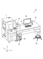
- FIG. 1 is a perspective view showing a configuration example of a specimen preparation system.
- 1A to 1C are schematic diagrams showing examples of operation modes of a specimen preparation device.
- FIG. 1 is a block diagram showing an example of the configuration of a specimen preparation system.
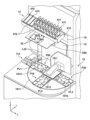
- FIG. 2 is a perspective view of a unit for providing an object to be observed and the structure of its surroundings, in which a cover member is not shown.
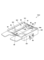
- 11 is a perspective view showing an example of the structure of a single holding portion.
- FIG. 11 is a perspective view showing an example of a configuration capable of detecting and identifying a guide member;
- FIG. 10A to 10C are schematic diagrams showing some examples of guide members that can be attached to the holding portion.
- FIG. 13 is a perspective view showing an example of the structure of a guide member.
- FIG. 4 is a perspective view of the retaining portion in an attached state.
- FIG. 13 is a perspective view of a state in which the plate PL is held by the holding portion in an attached state.
- 9C is a schematic cross-sectional view taken along line d1-d1 in FIG. 9B.
- 1 is a flowchart showing a procedure for preparing a specimen.
- [About the specimen preparation system] 1 is a perspective view showing an example of the overall configuration of a specimen preparation system SY according to an embodiment.
- the system SY includes a specimen preparation device 1, a workbench 91, an observation object preparation device 92, a chair 93, an input device 94, a computer 95, a display terminal 96, and an input terminal 97.
- the X direction, Y direction, and Z direction that intersect with each other are shown (they may also be shown in other figures described later).
- the X direction is one direction in the horizontal direction of the specimen preparation device 1, and corresponds to the left-right direction or width direction.
- the Y direction is another direction perpendicular to the one direction in the horizontal direction of the specimen preparation device 1, and corresponds to the front-back direction or depth direction.
- the Z direction is the vertical direction of the specimen preparation device 1, and corresponds to the up-down direction or height direction.
- the -Y direction side corresponds to the front side
- the +Y direction side corresponds to the back side.
- the +Z direction side corresponds to the upper side
- the -Z direction side corresponds to the lower side.
- the specimen preparation device 1 prepares a predetermined observation specimen using an observation object provided by an operator.
- the observation object is a tissue piece obtained by slicing a block of tissue collected from a subject such as a patient and solidified with paraffin or the like (observation object OB, described later).
- the observation specimen is prepared by placing the observation object on a light-transmitting plate (observation specimen SPL, described later).
- This plate can also be expressed as a slide glass (microscope slide), a specimen plate, a plate for placing an observation object, a plate for optical observation, etc. (plate PL, described later).
- the working subject is an entity that performs work related to specimen preparation, and is typically an operator such as a technician, but may also be a working robot equipped with an attachment mechanism (manipulator, etc.) for attaching an object to be observed.
- the working subject is referred to as a "worker”, and hereinafter will be simply referred to as a "worker”.
- the workbench 91 is a desk on which an operator performs tasks associated with the preparation of an observation specimen.
- An observation object preparation device 92, a display terminal 96, and an input terminal 97 are placed on the workbench 91. The operator can also use these to perform other tasks on the workbench 91, such as recording or managing information related to the observation specimen.
- the specimen preparation device 1 and the workbench 91 are arranged side by side in the X direction; that is, the workbench 91 is placed to the side of the specimen preparation device 1 (here, the +X direction side).
- the observation object preparation device 92 is a microtome that prepares tissue pieces as the observation object, but in other embodiments, it may be other devices such as medical equipment or experimental equipment.
- the observation object preparation device 92 is installed on the workbench 91 on the side of the specimen preparation device 1.
- the chair 93 is a chair with casters. This allows the operator to easily move between the specimen preparation device 1 and the work table 91 while sitting on the chair 93 when performing work.
- the input device 94 is a foot switch installed below the workbench 91, and an operator can perform operation input by pressing the input device 94 with his/her foot.
- the input device 94 is electrically connected to the specimen preparation device 1 by a cable (not shown), and the specimen preparation device 1 proceeds with a work step in response to operation input to the input device 94, the details of which will be described later.
- the input device 94 may be wirelessly connected to the specimen preparation device 1.
- the input device 94 may be installed on the work table 91.
- the input device 94 may be a device that performs input by recognizing the operator's voice, thoughts, and the like.
- the computer 95 is a general-purpose computer, and is installed below the workbench 91 here, but it may be installed in a position that prevents the operator from accidentally interfering with the computer 95.
- the display terminal 96 may be a known display or monitor, such as a liquid crystal display.
- the input terminal 97 may be a known input device, such as a keyboard or mouse. For example, the operator can use the input terminal 97 to manage information about the observation specimen while visually checking information showing the plate and the observed object on the display terminal 96.
- the specimen preparation device 1 includes a pre-processing unit 11, a post-processing unit 12, a specimen storage unit 13, a transfer unit 14, and a unit 15 for attaching an object under observation.
- the specimen preparation device 1 further includes a cover member C that can be opened and closed between the inside and outside of the housing, and the pre-processing unit 11, the post-processing unit 12, the specimen storage unit 13, the transfer unit 14, and a part of the unit 15 for attaching an object under observation are disposed inside the housing.
- the pre-processing unit 11 includes units 111 to 114 that perform pre-processing, which is processing before the attachment of an object under observation.
- the post-processing unit 12 includes units 121 to 123 that perform post-processing, which is processing after the attachment of an object under observation.
- the specimen storage unit 13 is a unit that stores (or houses or keeps) the prepared observation specimens.
- the specimen storage unit 13 may be simply referred to as a storage unit, a specimen storage unit (or simply a storage unit), a specimen storage unit (or simply a storage unit), etc.
- the transfer unit 14 is a manipulator capable of grasping a plate, and receives the plate PL to which the object to be observed has been attached from the post-processing unit 12 as the observation specimen SPL, and transfers it to the specimen storage unit 13.
- the unit 15 for applying an observation object is configured to be accessible by an operator when applying an observation object to the plate PL.
- the unit 15 is installed at an access point (referred to as an observation object application position or simply as application position P10) by the operator when applying an observation object such that at least the application position P10 is exposed outside the housing of the specimen preparation device 1. This allows the operator to access the unit 15 and apply an observation object prepared by the observation object preparation device 92 to the plate PL at the application position P10.
- the unit 15 may be expressed as an operator-subject access unit or the like in terms of being an access target by an operator, or may be expressed as an observation object receiving unit or the like in terms of receiving an observation object from an operator.
- the cover member C is used in a closed state during specimen preparation. It is also used in an open state during maintenance of the specimen preparation device 1, during the supply of a new plate PL, or during the preparation stage for specimen preparation (replacement of the guide member 411, which will be described later).
- the specimen preparation device 1 further includes a control unit 17.
- the control unit 17 performs drive control of the pre-processing unit 11, the unit 15, and the post-processing unit 12, and also performs management control of the entire specimen preparation device 1.
- the control unit 17 also performs drive control dedicated to driving the transfer unit 14.
- the control unit 17 may be formed by dividing it into multiple units.
- the pre-treatment section 11 includes a plate storage section 111, a transport unit 112, a printing unit 113, and a reading unit 114.
- the plate storage section 111 is a magazine (which may be expressed as a cartridge, a cassette, or the like) that stores plates PL before an object under observation OB is attached thereto, that is, washed or unused plates PL to be used for preparing an observation specimen SPL.
- the plate storage section 111 stores a plurality of plates PL and is capable of sending the plurality of plates PL one by one in sequence to the transport unit 112.
- the transport unit 112 is a transport belt, which transports the plates PL sent out from the plate storage section 111 one by one toward the unit 15.
- the printing unit 113 is an inkjet recording head in this embodiment, and prints on the plate PL being transported by the transport unit 112, for example, providing predetermined identification information 1131 (shown as "plate PL0" in the figure for ease of understanding).
- predetermined identification information 1131 shown as "plate PL0" in the figure for ease of understanding.
- a two-dimensional code is used as the identification information 1131, but letters, numbers, symbols, figures, etc. may be used alternatively/additionally.
- the reading unit 114 reads the identification information 1131 attached to the plate PL0 and outputs the result to the computer 95.
- the computer 95 can also display the contents indicating the identification information 1131 on the display terminal 96. This makes it possible to associate the identification information 1131 with (the information of) the object under observation attached to the plate PL to which it is attached, and to manage the information individually.
- the unit 15 for applying an observed object includes a rotating support table (moving support table) 1511, a plurality of (four in this case) holding parts 1512, a liquid supply unit 153, and a transfer unit 155.
- the rotating support table 1511 is configured to be rotatable about its center as the rotation axis, and rotates by a predetermined angle in response to an operational input to the input device 94.
- the plurality of holding parts 1512 are typically disposed at equal intervals around the rotation axis, and are moved in sequence to application position P10, for example, in response to an operational input to the input device 94.
- the four holding parts 1512 are disposed at equal intervals, and therefore the rotation angle of the rotation support base 1511 per rotation by an operation input to the input device 94 is 90 degrees.
- the following description will be given focusing on one of the multiple holding parts 1512.
- one of the holding parts 1512 receives and holds the plate PL with the identification information 1131 from the transport unit 112 at the receiving position P00 (for distinction, shown as “plate PL1" in the figure).
- the holder 1512 holding the plate PL1 is moved to the attachment position P10 by the rotation of the rotating support base 1511.
- This allows the operator to attach the object under observation OB to the plate PL1 using a tool T11 such as tweezers (for distinction, this is shown as "plate PL2" in the figure).
- a tool T11 such as tweezers
- the holder 1512 holding the plate PL1 is moved to the attachment position P10, it is inclined at a predetermined angle (tilt angle) so that the side in the direction of the central axis of rotation of the rotating support base 1511 is lower.
- the tilt angle in this embodiment may be, for example, about 0.5 to 5 degrees, and is about 1 degree in this embodiment.
- the liquid supply unit 153 is capable of supplying liquid from a nozzle 1531, and when applying liquid to the object under observation OB, the liquid is supplied onto the plate PL2 in the inclined posture at the application position P10.
- the liquid may be a solution or chemical that has substantially no chemical effect on the object under observation OB, and while pure water is used in this embodiment, saline solution or the like may be used in other embodiments. The details will be described later, but a guide member 411 (see FIG. 4) is attached to the holding part 1512, and a liquid pool is formed on the plate PL2 when liquid is supplied from the nozzle 1531.
- the observation object OB When an operator places an observation object OB on the supplied liquid, the observation object OB spreads appropriately (without wrinkles, etc.) on the plate PL2 by being placed on the supplied liquid. After that, the supplied liquid is discharged by a drainage section 56 (see FIG. 5 ) provided on the rotation shaft side of the rotating support table 1511, as will be described in detail later.
- a drainage section 56 (see FIG. 5 ) provided on the rotation shaft side of the rotating support table 1511, as will be described in detail later.
- the observation object OB when the liquid between the plate PL2 and the observation object OB is discharged, it flows while being guided by the guide member 411, and the observation object OB approaches the fixing position OC virtually set on the plate PL2 with the flow of the discharged liquid, and is seated and fixed.
- the plate PL2 with the object to be observed OB attached moves to a transfer position P20 for transferring the plate PL2 to the transfer unit 155 by further rotation of the rotary support base 1511 (shown as "plate PL3" in the figure for distinction).
- the inclined posture of the holding part 1512 that has been moved to the transfer position P20 is released and returned to a horizontal posture.
- the transfer unit 155 receives the plate PL3 from the holding part 1512 and transfers it to the post-processing part 12, as will be described in detail later.
- the holding part 1512 that transferred the plate PL3 to the transfer unit 155 moves again to the receiving position P00 by two rotations.
- position P30 which is a position between the delivery position P20 and the receiving position P00 and is the opposite position of the application position P10, may be used for cleaning the holding portion 1512, etc.
- the delivery of the plate PL3 to the loading/unloading unit 155 may be performed at position P30 instead of position P20.
- the post-processing section 12 includes a heating unit 122 and a confirmation unit 123.
- the post-processing section 12 further includes a transporting unit 121 that transports the plate PL in the heating unit 122.
- the transporting unit 121 is a walking beam type transport device, and includes a specimen mounting section 1211 and a specimen transport mechanism 1212.
- the specimen mounting section 1211 is a long plate material on which a plurality of plates PL accompanied by an object under observation OB can be mounted one by one at a predetermined position.
- the specimen transfer mechanism 1212 includes a pair of beam members arranged on both sides of the specimen placement section 1211, and a drive mechanism for driving the beam members.
- the pair of beam members move vertically and horizontally in parallel at the same time. Specifically, the pair of beam members are successively raised, moved in one transport direction (feed operation), lowered, and moved in the other transport direction (return operation) in this order, whereby the plate PL on the specimen placement section 1211 is intermittently transferred in one direction.
- the transfer unit 121 receives plate PL3 from the loading/unloading unit 155 (for distinction, shown as “plate PL4" in the figure) and transfers it to the transfer terminal end 1211a (for distinction, shown as "plate PL5" in the figure).
- the specimen mounting section 1211 may simply be referred to as a mounting section.
- the specimen transfer mechanism 1212 may simply be referred to as a transfer mechanism, a specimen transport mechanism (or simply a transport mechanism), or the like.
- the heating unit 122 is installed below the specimen mounting section 1211, and heats the plate PL4 placed on the specimen mounting section 1211 and the object under observation OB placed thereon. This causes the liquid on the plate PL4 to evaporate due to heating, thereby stretching the object under observation OB.
- the heating unit 122 may be expressed as a temperature processing unit, etc., or from a similar perspective, may be expressed as a temperature processing unit, object under observation stretching unit, etc.
- the confirmation unit 123 is disposed at the transfer end 1211a of the specimen placement section 1211, and confirms the state of the observation object OB (i.e., the observation specimen SPL) on the plate PL5 that has been transferred to the transfer end 1211a while being heated by the heating unit 122.
- the confirmation unit 123 may be a known imaging device, and may additionally be a known illumination device.
- the confirmation unit 123 captures the observation object OB on the plate PL5, records it as image information, and associates it with the identification information 1131.
- the confirmation unit 123 can also confirm the processing state of the observation object OB on the plate PL5, make a predetermined judgment, and output the results of the confirmation and judgment to the computer 95.
- This makes it possible to properly manage the observation object OB on the plate PL5 as the observation specimen SPL by the identification information 1131 attached to the plate PL5, together with information indicating the results of the confirmation and judgment.
- the computer 95 can also display information indicating whether the observation specimen SPL has been properly prepared on the display terminal 96.
- the above confirmation and judgment may be performed by the computer 95. Also, by displaying an image on the display terminal 96, the operator can visually confirm the observation object OB on the plate PL5.
- the plate PL5 together with the object to be observed OB attached thereto, is transferred as the observation specimen SPL to the specimen storage section 13 by the transfer unit 14.
- [Configuration of specimen preparation system] 3 is a block diagram showing an example of the configuration of a specimen preparation system SY.
- a computer 95 is connected to an input device 94, a display terminal 96, an input terminal 97, and the specimen preparation device 1 so as to be able to communicate with each other, and the specimen preparation device 1 executes a specimen preparation operation based on communication with the computer 95.
- an operator can use the input terminal 97 to perform operation input, and can set information related to specimen preparation as setting information prior to specimen preparation.
- an operator can use the input device 94 to perform operation input, and can instruct the specimen preparation device 1 on the necessary operations when preparing a specimen.
- the computer 95 outputs a control signal to the specimen preparation device 1 based on the operation input, and also outputs information to be presented to the operator at that time to the display terminal 96.
- the input terminal 97 and the display terminal 96 may be configured as one unit.
- the control unit 17 controls the driving of the pre-treatment unit 11, the post-treatment unit 12, the transfer unit 14, and the unit 15 for providing an object to be observed, and the observation specimen SPL is prepared in sequence according to the procedure described with reference to FIG.
- the control unit 17 includes a CPU (Central Processing Unit) 171 and a memory 172, and setting information set using the input terminal 97 can be stored in the memory 172 through communication with the computer 95.
- the control unit 17 reads out a program for executing specimen preparation from the memory 172 and executes it with the CPU 171, and performs the above-mentioned drive control based on the setting information stored in the memory 171.
- the setting information may be stored in another storage device such as an SSD.
- the control unit 17 may be configured to incorporate a control board on which electronic components such as an ASIC (Application Specific Integrated Circuit) are mounted. That is, each function of the control unit 17 may be realized by either hardware or software.
- ASIC Application Specific Integrated Circuit
- [Applying the object to be observed onto the plate] 4 is a perspective view of the structure of the unit 15 for providing an observation subject and its surroundings, with the cover member C not shown.
- a storage table 41 for storing a guide member 411 is installed above the unit 15.
- a sensor 42 is installed between the unit 15 and the storage table 41 so as to be located above the receiving position P00.
- the specimen preparation device 1 further includes a storage installation section 1S on which the storage table 41 is provided, and a sensor installation section 1K on which the sensor 42 is installed.
- the storage installation section 1S is set above the unit 15 so as to be located at a height that can be reached by the hand of an operator seated on a chair 93.
- the storage table 41 is configured in a box shape and includes a storage section 410 that stores a plurality of guide members 411 by type, and an identification display section 412 that indicates the type of guide members 411 stored in the storage section 410.
- the guide member 411 is formed in a plate shape having a predetermined outer shape, the details of which will be described later.
- the accommodation section 410 is formed in a slit shape on the upper surface of the accommodation table 41, and a plurality of accommodation sections 410 are arranged side by side, and each accommodation section 410 accommodates the guide member 411 so as to hold the guide member 411 in an insertable and removable manner.
- the slits through which the guide member 411 can be inserted and removed may be formed at an incline with respect to the Z direction, so that the guide member 411 can be held in a position inclined by a predetermined angle.
- the slits of the accommodation section 410 are formed at an incline so that the guide member 411 can be easily inserted and removed while the operator is seated on the chair 93. This improves the work efficiency.
- the identification display parts 412 are arranged corresponding to the storage positions of the respective types of guide members 411, and although details will be described later, in this example, the identification display parts 412 are arranged to distinguish between three types of guide members 411 (see FIG. 7).
- the sensor 42 is attached to the sensor installation section 1K via the attachment section 42B above the receiving position P00.
- the sensor 42 may be an optical sensor such as a laser or an infrared sensor.
- the sensor 42 is aligned so that its optical axis L42 passes through the holding section 1512 of the receiving position P00. With this configuration, the sensor 42 detects the guide member 411 attached to the holding section 1512 of the receiving position P00, and this makes it possible to further identify the type of guide member 411 if one is attached. Details will be described later, but from this perspective, the receiving position P00 may also be expressed as a specific position P00.
- Figure 5 is an oblique view showing an example of the structure of a single holding portion 1512, showing the holding portion 1512 in an unattached state where the guide member 411 is not attached.
- the holding portion 1512 includes a placement portion 51, an attachment portion 52, a specific auxiliary portion 53, a regulating portion 54, a drainage portion 56, and a drainage path 57.
- the holding portion 1512 also includes a receiving portion 55 for receiving the plate PL.
- the holding portion 1512 also includes a tilting mechanism 58 that moves the holding portion 1512 between horizontal positions.
- the mounting portion 51 is formed so that the plate PL can be placed on the upper surface of the main body of the holding portion 1512.
- the mounting portion 51 is provided with a recessed portion 511 that is recessed into the mounting surface (plate contact surface) on which the plate PL comes into contact and is placed.
- the recessed portion 511 is formed continuously toward the drainage portion 56, as will be described in detail later.
- the mounting portion 52 is provided so as to surround the mounting portion 51, and is provided in pair substantially on both sides of the mounting portion 51.
- the mounting portion 52 includes a screw hole 521 for mounting the guide member 411, and the guide member 411 is attached and fixed to the mounting portion 52 by screwing.
- the screw holes 521 are provided in pair on both sides of the mounting portion 51, and can function as alignment portions for aligning the guide member 411.
- the mounting manner of the guide member 411 may be fixed by a magnet or the like, or may simply be fitted, engaged, or locked. Incidentally, the guide portion contact surface with which the guide member 411 comes into contact and the plate contact surface with which the plate PL comes into contact are formed on the same plane.
- the identification auxiliary section 53 includes an opening 531 that is used to assist in identifying the guide member 411 when the guide member 411 is attached.
- a pair of openings 531 are provided on both sides of the mounting section 51, and a pair of sensors 42 can also be provided corresponding to the openings 531. Details will be described later, but with this configuration, the pair of sensors 42 respectively detect the presence or absence of the pair of openings 531 (see Figure 6). Based on the detection results of the sensors 42, the control unit 17 determines the presence or absence of the guide member 411, and if a guide member 411 is present, identifies its type.
- the receiving section 55 is provided at the receiving position P00 with an open shape so that it can receive the plate PL received from the transport unit 112, and can also be expressed as a receiving port 55.
- the receiving section 55 functions as an insertion port for the plate PL, and can also function as part of the placement section 51.
- the determining portion 54 is a wall portion formed to surround an area that envelops the guide portion contact surface and the plate contact surface, and is provided to determine the position of a guide member 411 of a predetermined size.
- the determining portion 54 is provided by a rectangular wall portion that forms three sides except for the side on the receiving portion 55 side. By providing such a wall portion, it becomes possible to accumulate liquid on the mounting portion 51 when the holding portion 1512 (mounting portion 51) is tilted.
- the determining portion 54 formed by such a wall portion functions as an alignment portion for aligning the guide member 411, and can also function as a part of the attachment portion 52. The alignment of the guide member 411 by the determining portion 54 can be achieved by the edge of the guide member 411 abutting the wall portion that forms the determining portion 54.
- the drainage section 56 is provided at a position opposite to the receiving section 55 (on the opposite side of the receiving section 55) and is configured to be able to discharge the liquid supplied from the nozzle 1531 of the liquid supply unit 153 at the application position P10 after the observation object OB is placed on the liquid.
- the drainage section 56 can also be used to align the plate PL inserted from the receiving section 55.
- the drainage section 56 functions as an alignment section for aligning the plate PL, and can also function as a part of the mounting section 51.
- the drainage section 56 has a drainage port 56a for liquid collected in the drainage path 57 described below.
- the drainage section 56 also has a drainage port 56b for liquid supplied onto the plate PL placed on the mounting section 51.
- the drainage port 56a and the drainage port 56b are provided in communication with each other and communicate with a drainage recovery section (not shown).
- the drainage liquid supplied from the nozzle 1531 at the application position P10 flows over the plate PL and is discharged through the drainage port 56b to a drainage recovery section (not shown) and collected.
- the drainage path 57 is provided so as to communicate with the recessed portion 511 and to be connected to the drainage section 56. Excess liquid supplied from the nozzle 1531 at the application position P10 flows through the recessed portion 511 and/or over the plate PL and is collected in the drainage path 57. The liquid is then discharged through the drainage port 56a to a drainage collection section (not shown) and collected.
- the tilting mechanism 58 is configured to be able to tilt the body of the holding section 1512 including the mounting section 51, and can, for example, place the mounting section 51 in a horizontal or inclined position based on a control signal from the control unit 17.
- the receiving section 55 can receive the plate PL from the transport unit 112, and when the mounting section 51 is in an inclined position, the draining section 56 is located below the receiving section 55. That is, the tilting mechanism 58 is able to execute the tilting movement of the mounting section 51, whereby the receiving section 55 can move between a position for receiving the plate PL from the transport unit 112 (first position: horizontal position) and a position where the draining section 56 is below the receiving section 55 (second position: inclined position).
- the tilting mechanism 58 may have a known configuration as long as it is configured to be able to change the posture of the mounting unit 51 in both directions, that is, from one of the horizontal posture and the inclined posture to the other.
- the tilting mechanism 58 may include a motor connected to a rotation shaft that supports the lower part of the holding unit 1512, and a motor driver that drives the motor to rotate the holding unit 1512.
- the plate PL is placed on the mounting part 51 in a horizontal position, and then the mounting part 51 is tilted at the application position P10, and the observation object OB is placed on the liquid supplied from the nozzle 1531 to the tilted plate PL so as to include the fixing position OC, and then the liquid drainage part 56 starts to discharge the liquid.
- the observation object OB is gradually fixed on the plate PL from the receiving part 55 side toward the drainage part 56 side, and when the discharge of the liquid is completed, the entire surface of the observation object OB is fixed at the fixing position OC on the plate PL. Note that when discharging the liquid from the tilted mounting part 51, it is also possible to improve the drainage efficiency by further tilting the mounting part 51.
- FIG. 6 is a perspective view showing an example of a configuration capable of detecting and identifying the guide member 411, and in this example, the positional relationship between the pair of sensors 42 and the pair of openings 531 is mainly shown.
- the pair of openings 531 are each located on the optical axis L42 of the pair of sensors 42.
- one of the sensors 42 is referred to as the sensor 42a
- its optical axis L42 is referred to as the optical axis L42a
- the corresponding opening 531 is referred to as the opening 531a.
- the other sensor 42 is referred to as the sensor 42b
- its optical axis L42 is referred to as the optical axis L42b
- the corresponding opening 531 is referred to as the opening 531b.
- the sensor 42a outputs a low level signal (L signal) when the opening 531a is detected, and outputs a high level signal (H signal) when the opening 531a is not detected (here, when the optical axis L42a is blocked by the guide member 411).
- the sensor 42b outputs an L signal when the opening 531b is detected, and outputs an H signal when the opening 531b is not detected.
- the detection of the pair of openings 531 by the pair of sensors 42 is performed when the holding portion 1512 (mounting portion 51) is in a horizontal position.
- FIG. 7 shows three types of guide members 411a, 411b, and 411c as examples of the guide members 411 that can be attached to the holding portion 1512. These are stored in the storage portion 410 at positions corresponding to the identification display portions 412, and can be selectively attached to the holding portion 1512.
- FIG. 8 shows, as an example, a perspective view of the guide member 411a as viewed from below. In the following description, when there is no particular need to distinguish between the guide members 411a, 411b, and 411c, they will simply be referred to as guide members 411.
- the guide member 411 includes a guide section 71, a connecting section 72, a lyophobic section 73, an attachment section 74, and a covering section 75.
- the guide section 71 is provided so as to be able to guide the object under observation OB to a predetermined position, and in this example includes a pair of left and right mounting members 71L and 71R.
- the connecting section 72 connects the pair of mounting members 71L and 71R. The distance between the pair of mounting members 71L and 71R may be determined based on the size of the plate PL and the size of the object under observation OB.
- a recess 721 is formed in the connecting portion 72, and the connecting portion 72 can be fitted into the drainage portion 56 by the recess 721.
- the recess 721 functions as an alignment portion for aligning the guide member 411.
- the lyophobic portion 73 is formed on the surfaces of the pair of mounting members 71L and 71R and the connecting portion 72, and can be formed, for example, by a water-repellent treatment on at least the upper surfaces thereof. As shown by the dashed lines in the figure, the lyophobic portion 73 is formed only on the inside of a C-shaped frame formed by the pair of mounting members 71L and 71R and the upper surfaces of the connecting portion 72. According to this configuration, the liquid supplied to the plate PL by the nozzle 1531 of the liquid supply unit 153 at the application position P10 is retained on the plate PL by the lyophobic effect (water-repellent effect) of the lyophobic part 73, forming a liquid pool. Then, the object under observation OB on the liquid pool formed on the plate PL can be appropriately guided within the frame of the pair of mounting members 71L and 71R and the connecting part 72.
- the shapes of the guide portion 71, connecting portion 72, and lyophobic portion 73 differ among the guide members 411a to 411c, which allows the guide members 411a to 411c to be selectively used depending on the shape, size, type, etc. of the object under observation OB and the intended use.
- the mounting portion 74 is used to attach the main body of the guide member 411 to the attachment portion 52 of the holding portion 1512, and in this example, includes a fixing portion 741 and an aligned portion 742 as shown in Fig. 8.
- the fixing portion 741 is used to fix the guide member 411 to the attachment portion 52.
- the aligned portion 742 corresponds to the screw hole 521, which is one of the alignment portions of the guide member 411 (see Fig. 5).
- the fixing portion 741 and the aligned portion 742 are provided in pairs on the left and right corresponding to the pair of attachment members 71L and 71R.
- the fixing portion 741 is the head of a screw
- the aligned portion 742 is a screw portion corresponding to the screw hole 521
- the guide member 411 can be attached to the attachment portion 52 by screwing.
- the fixing portion 741 may be a grip portion and the aligned portion 742 may be a magnet.
- the configuration of the mounting portion 74 described above is the same for the guide members 411a to 411c, and any one of the guide members 411a to 411c can be used.
- the state in which any of the guide members 411a to 411c is not attached to the holding portion 1512 may be expressed as an unattached state (unmounted state). Additionally, the state in which any of the guide members 411a to 411c is attached to the holding portion 1512 may be expressed as an attached state (mounted state).
- the covering portion 75 is provided on each of the pair of mounting members 71L and 71R in correspondence with the specific auxiliary portion 53, at least partially covers the specific auxiliary portion 53, and closes at least one of the pair of openings 531a and 531b in this example.
- the guide member 411a closes both the openings 531a and 531b;
- the guide member 411b closes one of the openings 531a and 531b (here, the opening 531b);
- the guide member 411c closes the other of the openings 531a and 531b (here, the opening 531a).
- the control unit 17 can determine the presence or absence of a guide member 411 based on the detection results of the pair of sensors 42a and 42b, and can also identify the type of guide member 411 if it is present (see Figures 5 and 6). for example: When both the sensor 42a and the sensor 42b output an L signal, the holding portion 1512 is in an unattached state; When one or both of the sensors 42a and 42b output an H signal, the holding portion 1512 is in an attached state. are determined by the control unit 17, respectively.
- the guide member 411 attached to the holding portion 1512 is the guide member 411a;
- the guide member 411 attached to the holding portion 1512 is the guide member 411b; and
- the guide member 411 attached to the holding portion 1512 is the guide member 411c.
- FIG. 9A shows an oblique view of the holding portion 1512 with the guide member 411a attached.
- FIG. 9B shows an oblique view of the holding portion 1512 with the guide member 411a attached and the plate PL being held therein.
- FIG. 9C shows a schematic cross-sectional view taken along line d1-d1 in FIG. 9B.
- the recess 511 is formed continuously toward the drainage section 56, so that excess liquid supplied from the nozzle 1531 of the liquid supply unit 153 at the application position P10 can be collected in the drainage path 57 via the recess 511.
- [Procedure for specimen preparation] 10 is a flowchart showing an example of a procedure for preparing an observation sample SPL. This flowchart is mainly performed by an operator and/or the control unit 17.
- step S1000 (hereinafter simply referred to as "S1000"; the same applies to other steps described below), the operator attaches one of the guide members 411a to 411c to each of the multiple holding parts 1512. Note that the multiple guide members 411 attached to the multiple holding parts 1512 may be the same to prevent confusion, but may also be partially different depending on the intended use.
- the operator sets the specimen preparation information, including information on the guide member 411 attached in S1000, as setting information.
- Other examples of setting information may include information for managing the observation specimen SPL, such as the type and attributes of the observation specimen SPL. This operation is performed via the input terminal 97, and the setting information is registered in the computer 95. This allows the operator to check the contents of the observation specimen SPL that will be prepared in this step and thereafter.
- control unit 17 rotates the rotating support table 1511 based on the communication between the specimen preparation device 1 and the computer 95 in accordance with the registration in S1010.
- control unit 17 sequentially determines whether the holding portion 1512, which is moved sequentially to the receiving position P00 by the rotation of the rotating support base 1511, is in an attached state (a state in which the guide member 411 is attached) or an unattached state (a state in which the guide member 411 is not attached), and if it is in an attached state, further identifies the type of the attached guide member 411. This determination and identification is performed based on the detection results of the sensors 42a and 42b.
- a comparison is made between the setting information registered in the computer 95 in S1010 and the information indicating the determination result and the identification result obtained in S1030, based on the communication between the specimen preparation device 1 and the computer 95.
- the comparison may be made by the control unit 17, or may be made by the computer 95 based on the communication between the specimen preparation device 1 and the computer 95. If all of the determination results and identification results obtained in S1030 correspond to the setting information registered in computer 95 in S1010, the process proceeds to S1050, otherwise the process proceeds to S1100. For example, if the information indicating that guide member 411 is not attached and, if guide member 411 is attached, the information specifying the type of guide member 411, match the setting information registered in S1010, the process proceeds to S1050.
- the operator checks and returns to S1010 if the guide member 411 does not need to be reinstalled. On the other hand, if the guide member 411 does need to be reinstalled, the operator returns to S1000.
- the operator can perform the specimen preparation work. Specifically, while removing the observed object OB from the observed object preparation device 92, the operator applies the observed object OB to the plate PL of the holding part 1512, which is moved in sequence to the application position P10 by operation input using the input device 94.
- the control unit 17 determines whether or not to end the specimen preparation work. When the operator ends the specimen preparation work, the operator can give an instruction to end the work via the input terminal 97. This determination is made based on communication between the specimen preparation device 1 and the computer 95. When the specimen preparation work is to be ended, this flowchart ends, and when not, the process returns to S1050.
- the operator attaches a desired one of the guide members 411a to 411c to the multiple holding parts 1512.
- the operator registers the setting information in the computer 95 by operating the input terminal 97.
- the control unit 17 in the specimen preparation device 1 rotates the rotating support base 1511 to identify the type of guide member 411 attached to each of the multiple holding parts 1512.
- the operator then attaches the plate PL of the holding part 1512, which is moved in sequence to the attachment position P10 by operating the input device 94.
- the observation specimen SPL prepared in this manner is stored in sequence in the specimen storage part 13 by the transfer unit 14.
- the operator manages the information of the observation specimen SPL while referring to the display terminal 96 as necessary.
- the control unit 17 identifies the guide members 411 attached to the individual holders 1512, and performs control to prepare the observation specimen SPL based on the results. For example, if the attachment manner of the guide members 411 is as intended by the operator, the operator can properly perform the specimen preparation work. On the other hand, if the attachment manner of the guide members 411 is not as intended by the operator, a confirmation notice is output, and the operator will not make a mistake in the type of observation object OB to be attached to the plate PL.
- the observation specimen OB can be fixed to a predetermined position on the plate PL and the fixing position can be adjusted, which makes it possible to more properly prepare the observation specimen SPL.
- each element is shown by a name related to its function, but each element is not limited to having the content described in the embodiment as its main function, and may have it as an auxiliary function.
- the individual terms described in this specification are used only for the purpose of explaining the present invention, that is, the present invention is not limited to the strict meaning of the terms.
- the term “apparatus” may be replaced by “unit/assembly/device/module” or vice versa.
- the term “move” for an object may be replaced by “convey/transfer” or vice versa.
Landscapes
- Physics & Mathematics (AREA)
- Health & Medical Sciences (AREA)
- Life Sciences & Earth Sciences (AREA)
- Chemical & Material Sciences (AREA)
- Analytical Chemistry (AREA)
- Biochemistry (AREA)
- General Health & Medical Sciences (AREA)
- General Physics & Mathematics (AREA)
- Immunology (AREA)
- Pathology (AREA)
- Sampling And Sample Adjustment (AREA)
Priority Applications (4)
| Application Number | Priority Date | Filing Date | Title |
|---|---|---|---|
| JP2025523756A JPWO2024247125A1 (https=) | 2023-05-30 | 2023-05-30 | |
| PCT/JP2023/020163 WO2024247125A1 (ja) | 2023-05-30 | 2023-05-30 | 標本作製装置およびガイド部材 |
| CN202380098440.2A CN121152963A (zh) | 2023-05-30 | 2023-05-30 | 标本制作装置及引导构件 |
| US19/390,801 US20260104430A1 (en) | 2023-05-30 | 2025-11-17 | Specimen preparation device and guide member |
Applications Claiming Priority (1)
| Application Number | Priority Date | Filing Date | Title |
|---|---|---|---|
| PCT/JP2023/020163 WO2024247125A1 (ja) | 2023-05-30 | 2023-05-30 | 標本作製装置およびガイド部材 |
Related Child Applications (1)
| Application Number | Title | Priority Date | Filing Date |
|---|---|---|---|
| US19/390,801 Continuation US20260104430A1 (en) | 2023-05-30 | 2025-11-17 | Specimen preparation device and guide member |
Publications (1)
| Publication Number | Publication Date |
|---|---|
| WO2024247125A1 true WO2024247125A1 (ja) | 2024-12-05 |
Family
ID=93657187
Family Applications (1)
| Application Number | Title | Priority Date | Filing Date |
|---|---|---|---|
| PCT/JP2023/020163 Ceased WO2024247125A1 (ja) | 2023-05-30 | 2023-05-30 | 標本作製装置およびガイド部材 |
Country Status (4)
| Country | Link |
|---|---|
| US (1) | US20260104430A1 (https=) |
| JP (1) | JPWO2024247125A1 (https=) |
| CN (1) | CN121152963A (https=) |
| WO (1) | WO2024247125A1 (https=) |
Citations (3)
| Publication number | Priority date | Publication date | Assignee | Title |
|---|---|---|---|---|
| JPH05504627A (ja) * | 1990-03-02 | 1993-07-15 | ベンタナ・メデイカル・システムズ・インコーポレーテツド | 自動化生物学的反応装置 |
| WO2021044965A1 (ja) * | 2019-09-04 | 2021-03-11 | 平田機工株式会社 | 標本作製装置 |
| US20210293671A1 (en) * | 2020-03-11 | 2021-09-23 | Novodiax, Inc. | Devices and components for automated tissue processing and staining and uses thereof |
-
2023
- 2023-05-30 CN CN202380098440.2A patent/CN121152963A/zh active Pending
- 2023-05-30 JP JP2025523756A patent/JPWO2024247125A1/ja active Pending
- 2023-05-30 WO PCT/JP2023/020163 patent/WO2024247125A1/ja not_active Ceased
-
2025
- 2025-11-17 US US19/390,801 patent/US20260104430A1/en active Pending
Patent Citations (3)
| Publication number | Priority date | Publication date | Assignee | Title |
|---|---|---|---|---|
| JPH05504627A (ja) * | 1990-03-02 | 1993-07-15 | ベンタナ・メデイカル・システムズ・インコーポレーテツド | 自動化生物学的反応装置 |
| WO2021044965A1 (ja) * | 2019-09-04 | 2021-03-11 | 平田機工株式会社 | 標本作製装置 |
| US20210293671A1 (en) * | 2020-03-11 | 2021-09-23 | Novodiax, Inc. | Devices and components for automated tissue processing and staining and uses thereof |
Also Published As
| Publication number | Publication date |
|---|---|
| JPWO2024247125A1 (https=) | 2024-12-05 |
| US20260104430A1 (en) | 2026-04-16 |
| CN121152963A (zh) | 2025-12-16 |
Similar Documents
| Publication | Publication Date | Title |
|---|---|---|
| JP7637810B2 (ja) | 標本作製装置 | |
| US7649686B2 (en) | Box-type microscope apparatus | |
| CN110268299A (zh) | 带有可定位成像头的共焦显微镜 | |
| JP6046124B2 (ja) | 組織包埋カセットのマーキング装置 | |
| JP6889501B1 (ja) | 医療用スワブ収容方法及び医療用スワブ収容装置 | |
| KR20050093847A (ko) | 감시기능을 갖춘 분주장치 및 분주장치의 감시방법 | |
| CN112243456A (zh) | 多层培养容器观察系统、托架装置及多层培养容器观察装置 | |
| JP2004333573A (ja) | レンズ加工システム | |
| CA3049232A1 (en) | Slide identification sensor | |
| JP2021052144A (ja) | ウエーハの加工方法、及びウエーハの加工装置 | |
| WO2024247125A1 (ja) | 標本作製装置およびガイド部材 | |
| JP2014008715A (ja) | チップホルダ収納体の載置台 | |
| US8231829B2 (en) | Device for manipulating at least one specimen slide | |
| US12392688B2 (en) | Sample producing apparatus | |
| US20060012858A1 (en) | Microscope having a pivotable holding apparatus for optical components | |
| JP3711097B2 (ja) | 試験片供給装置とこれを用いた尿の検査装置 | |
| JP2008164521A (ja) | 薄切片標本作製装置 | |
| WO2024261826A1 (ja) | 標本格納庫および標本作製装置 | |
| US20220382034A1 (en) | Observation holder, observation apparatus, observation chip, and method of manufacturing observation chip | |
| EP4556913A1 (en) | Specimen measurement apparatus and specimen measurement method | |
| JP2004020281A (ja) | Dnaチップ反応容器およびdnaチップ読み取り装置 |
Legal Events
| Date | Code | Title | Description |
|---|---|---|---|
| 121 | Ep: the epo has been informed by wipo that ep was designated in this application |
Ref document number: 23939603 Country of ref document: EP Kind code of ref document: A1 |
|
| ENP | Entry into the national phase |
Ref document number: 2025523756 Country of ref document: JP Kind code of ref document: A |
|
| WWE | Wipo information: entry into national phase |
Ref document number: 2025523756 Country of ref document: JP |
|
| NENP | Non-entry into the national phase |
Ref country code: DE |