WO2024243159A1 - Systems and methods for closed-loop ultrasound and photoacoustic imaging - Google Patents
Systems and methods for closed-loop ultrasound and photoacoustic imaging Download PDFInfo
- Publication number
- WO2024243159A1 WO2024243159A1 PCT/US2024/030274 US2024030274W WO2024243159A1 WO 2024243159 A1 WO2024243159 A1 WO 2024243159A1 US 2024030274 W US2024030274 W US 2024030274W WO 2024243159 A1 WO2024243159 A1 WO 2024243159A1
- Authority
- WO
- WIPO (PCT)
- Prior art keywords
- ultrasound
- subsystem
- imaging
- imaging system
- target tissue
- Prior art date
- Legal status (The legal status is an assumption and is not a legal conclusion. Google has not performed a legal analysis and makes no representation as to the accuracy of the status listed.)
- Ceased
Links
Classifications
-
- A—HUMAN NECESSITIES
- A61—MEDICAL OR VETERINARY SCIENCE; HYGIENE
- A61B—DIAGNOSIS; SURGERY; IDENTIFICATION
- A61B8/00—Diagnosis using ultrasonic, sonic or infrasonic waves
- A61B8/44—Constructional features of the ultrasonic, sonic or infrasonic diagnostic device
- A61B8/4416—Constructional features of the ultrasonic, sonic or infrasonic diagnostic device related to combined acquisition of different diagnostic modalities, e.g. combination of ultrasound and X-ray acquisitions
-
- A—HUMAN NECESSITIES
- A61—MEDICAL OR VETERINARY SCIENCE; HYGIENE
- A61B—DIAGNOSIS; SURGERY; IDENTIFICATION
- A61B8/00—Diagnosis using ultrasonic, sonic or infrasonic waves
- A61B8/08—Clinical applications
- A61B8/0833—Clinical applications involving detecting or locating foreign bodies or organic structures
- A61B8/085—Clinical applications involving detecting or locating foreign bodies or organic structures for locating body or organic structures, e.g. tumours, calculi, blood vessels, nodules
-
- A—HUMAN NECESSITIES
- A61—MEDICAL OR VETERINARY SCIENCE; HYGIENE
- A61B—DIAGNOSIS; SURGERY; IDENTIFICATION
- A61B8/00—Diagnosis using ultrasonic, sonic or infrasonic waves
- A61B8/08—Clinical applications
- A61B8/0858—Clinical applications involving measuring tissue layers, e.g. skin, interfaces
-
- A—HUMAN NECESSITIES
- A61—MEDICAL OR VETERINARY SCIENCE; HYGIENE
- A61B—DIAGNOSIS; SURGERY; IDENTIFICATION
- A61B8/00—Diagnosis using ultrasonic, sonic or infrasonic waves
- A61B8/42—Details of probe positioning or probe attachment to the patient
- A61B8/4209—Details of probe positioning or probe attachment to the patient by using holders, e.g. positioning frames
- A61B8/4218—Details of probe positioning or probe attachment to the patient by using holders, e.g. positioning frames characterised by articulated arms
-
- A—HUMAN NECESSITIES
- A61—MEDICAL OR VETERINARY SCIENCE; HYGIENE
- A61B—DIAGNOSIS; SURGERY; IDENTIFICATION
- A61B8/00—Diagnosis using ultrasonic, sonic or infrasonic waves
- A61B8/42—Details of probe positioning or probe attachment to the patient
- A61B8/4272—Details of probe positioning or probe attachment to the patient involving the acoustic interface between the transducer and the tissue
- A61B8/4281—Details of probe positioning or probe attachment to the patient involving the acoustic interface between the transducer and the tissue characterised by sound-transmitting media or devices for coupling the transducer to the tissue
-
- A—HUMAN NECESSITIES
- A61—MEDICAL OR VETERINARY SCIENCE; HYGIENE
- A61B—DIAGNOSIS; SURGERY; IDENTIFICATION
- A61B8/00—Diagnosis using ultrasonic, sonic or infrasonic waves
- A61B8/46—Ultrasonic, sonic or infrasonic diagnostic devices with special arrangements for interfacing with the operator or the patient
- A61B8/467—Ultrasonic, sonic or infrasonic diagnostic devices with special arrangements for interfacing with the operator or the patient characterised by special input means
- A61B8/469—Ultrasonic, sonic or infrasonic diagnostic devices with special arrangements for interfacing with the operator or the patient characterised by special input means for selection of a region of interest
-
- A—HUMAN NECESSITIES
- A61—MEDICAL OR VETERINARY SCIENCE; HYGIENE
- A61B—DIAGNOSIS; SURGERY; IDENTIFICATION
- A61B8/00—Diagnosis using ultrasonic, sonic or infrasonic waves
- A61B8/48—Diagnostic techniques
- A61B8/488—Diagnostic techniques involving Doppler signals
-
- A—HUMAN NECESSITIES
- A61—MEDICAL OR VETERINARY SCIENCE; HYGIENE
- A61B—DIAGNOSIS; SURGERY; IDENTIFICATION
- A61B8/00—Diagnosis using ultrasonic, sonic or infrasonic waves
- A61B8/52—Devices using data or image processing specially adapted for diagnosis using ultrasonic, sonic or infrasonic waves
- A61B8/5215—Devices using data or image processing specially adapted for diagnosis using ultrasonic, sonic or infrasonic waves involving processing of medical diagnostic data
- A61B8/5238—Devices using data or image processing specially adapted for diagnosis using ultrasonic, sonic or infrasonic waves involving processing of medical diagnostic data for combining image data of patient, e.g. merging several images from different acquisition modes into one image
- A61B8/5246—Devices using data or image processing specially adapted for diagnosis using ultrasonic, sonic or infrasonic waves involving processing of medical diagnostic data for combining image data of patient, e.g. merging several images from different acquisition modes into one image combining images from the same or different imaging techniques, e.g. color Doppler and B-mode
-
- A—HUMAN NECESSITIES
- A61—MEDICAL OR VETERINARY SCIENCE; HYGIENE
- A61B—DIAGNOSIS; SURGERY; IDENTIFICATION
- A61B8/00—Diagnosis using ultrasonic, sonic or infrasonic waves
- A61B8/52—Devices using data or image processing specially adapted for diagnosis using ultrasonic, sonic or infrasonic waves
- A61B8/5215—Devices using data or image processing specially adapted for diagnosis using ultrasonic, sonic or infrasonic waves involving processing of medical diagnostic data
- A61B8/5238—Devices using data or image processing specially adapted for diagnosis using ultrasonic, sonic or infrasonic waves involving processing of medical diagnostic data for combining image data of patient, e.g. merging several images from different acquisition modes into one image
- A61B8/5261—Devices using data or image processing specially adapted for diagnosis using ultrasonic, sonic or infrasonic waves involving processing of medical diagnostic data for combining image data of patient, e.g. merging several images from different acquisition modes into one image combining images from different diagnostic modalities, e.g. ultrasound and X-ray
-
- A—HUMAN NECESSITIES
- A61—MEDICAL OR VETERINARY SCIENCE; HYGIENE
- A61B—DIAGNOSIS; SURGERY; IDENTIFICATION
- A61B8/00—Diagnosis using ultrasonic, sonic or infrasonic waves
- A61B8/08—Clinical applications
- A61B8/0808—Clinical applications for diagnosis of the brain
-
- A—HUMAN NECESSITIES
- A61—MEDICAL OR VETERINARY SCIENCE; HYGIENE
- A61B—DIAGNOSIS; SURGERY; IDENTIFICATION
- A61B8/00—Diagnosis using ultrasonic, sonic or infrasonic waves
- A61B8/58—Testing, adjusting or calibrating the diagnostic device
Definitions
- the present disclosure generally relates to photoacoustic imaging, and in particular, to a system and associated method for an imaging system having a scanning and coupling interface for five-dimensional closed-loop ultrasound and photoacoustic imaging.
- the present disclosure provides examples of a dual modality pulse echo ultrasound and photoacoustic imaging system that offers hands-free operation with volumetric and spectroscopic scanning (volume, time, optical wavelength/spectroscopy, etc.) leading to better imaging performance and reproducibility compared to current state-of-the art.
- volumetric and spectroscopic scanning volume, time, optical wavelength/spectroscopy, etc.
- the terms “operable to;’ “configured to,” and “capable of’ used herein are interchangeable.
- An imaging system for hybrid pulse-echo (PE) photoacoustic tomography (PAT) imaging with linear scanning and minimized system movement includes: a probe device, including: an ultrasound device (or an ultrasound subsystem) operable for detecting and processing acoustic signals including a transducer for generating an ultrasound signal, an optical subsystem operable for generating a light signal for application to a target tissue area; an optoacoustic coupling subsystem that integrates the light signal and the acoustic signals into a coaligned axis to accommodate transmission of light to the target tissue area and generation of ultrasound back to the ultrasound device; a scanning subsystem including a motor and a housing for the motor, the motor mechanically engaged with the probe device to actuate the probe device along a linear axis associated with a surface of the target tissue area for volumetric scanning; and a tissue coupling subsystem including a receiver plate positioned along the scanning subsystem, the receiver plate being operable to magnetically interface wi th a tissue coupler element position
- the imaging system can further include an articulating arm of the scanning subsystem, the housing of the scanning subsystem integrated onto the articulating arm to accommodate easier adjustment of the probe device along the target tissue area.
- the housing includes handles defined adjacent to the articulating arm to improve ergonomic usability, the handles are configured to engage with the optoacoustic coupling subsystem.
- the housing of the scanning subsystem can further include one or more linear bearings to accommodate smooth movement of the housing and the probe device along parallel rods that are part of the housing.
- the motor of the scanning subsystem can be a single-direction programmable linear motor that mechanically drives the probe device along the linear axis associated with a surface of the target tissue area. Further, the motor is positioned over the probe device to reduce an overall footprint of the imaging system.
- the tissue coupler element can include a paramagnetic or ferromagnetic washer that magnetically locks with the receiver plate.
- the receiver plate includes a recessed cutout and an embedded magnet that magnetically locks with the tissue coupler and reduces lateral motion between the target tissue area and the probe device.
- the optical subsystem can tune the light signal to a predetermined portion of an electromagnetic spectrum defining a predetermined wavelength.
- the imaging system can further include a computing device including a processor in communication with a memory, the memory including instructions executable by the processor to: apply the ultrasound signal and the light signal to the target tissue area; receive a return ultrasound signal and a return light signal from the target tissue area; and construct, based on the return ultrasound signal and the return light signal, one or more cross- sectional images of the target tissue area.
- a computing device including a processor in communication with a memory, the memory including instructions executable by the processor to: apply the ultrasound signal and the light signal to the target tissue area; receive a return ultrasound signal and a return light signal from the target tissue area; and construct, based on the return ultrasound signal and the return light signal, one or more cross- sectional images of the target tissue area.
- the memory can further include instructions executable by the processor to: apply one or more actuation signals to the motor of the scanning subsystem to actuate the probe device along the linear axis associated with a tissue surface; construct, based on the return ultrasound signal and the return light signal, a plurality of cross-sectional images of the target tissue area; and construct a volumetric image of the target tissue area using the plurality of cross-sectional images.
- the memory can further include instructions executable by the processor to: apply a Doppler ultrasound signal to the target tissue area; and receive a return Doppler ultrasound signal from the target tissue area.
- the memory can further include instructions executable by the processor to: apply an elastographic ultrasound signal to the target tissue area; and receive a return elastographic ultrasound signal from the target tissue area.
- FIG. 1 is a simplified block diagram showing a PE/PAT imaging system outlined herein;
- FIG. 2 is a simplified diagram showing an optoacoustic window technique for real-time optical observation during ultrasound stimulation
- FIG. 3 is a diagram showing a probe device of the system of FIG. 1 which includes an ultrasound subsystem, an optical subsystem, and an optoacoustic coupling subsystem;
- FIGS. 4A-4E are a series of illustrations showing a volumetric scanning subsystem of the system of FIG. 1;
- FIGS. 5A-5D are a series of illustrations showing a receiver plate and a coupler element of a tissue coupling subsystem of the system of FIG. 1;
- FIG. 6 is a diagram showing the coupler element of FIGS. 5A-5D engaged along a target tissue area
- FIGS. 7A and 7B are a pair of illustrations showing a first embodiment of the system including the tissue coupling subsystem and the volumetric scanning subsystem engaged with the probe device of FIG. 3;
- FIGS. 8A-8F are a series of illustrations showing an alternative embodiment of a probe device of the system of FIG. 1 in addition to the volumetric scanning subsy stem of FIGS. 4A-4E and the tissue coupling subsystem of FIGS. 7A and 7B;
- FIGS. 9A and 9B are a pair of illustrations showing a second embodiment of the system including the tissue coupling subsystem and the volumetric scanning subsystem engaged with the probe device of FIGS. 8A-8F;
- FIGS. 10A-10C are a series of diagrams showing various spatial quantities associated with ultrasound imaging
- FIGS. 11 A and 1 IB are a pair of diagrams showing sequential capture of a plurality of cross-sectional images by the probe device
- FIG. 12 is a simplified illustration showing how 7 higher resolution requires thinner slices in order to accurately observe two distinct objects
- FIG. 13 is a simplified diagram showing an example computing system for implementation of various functionalities of the system(s) of FIGS. 1-12; and [0030] FIGS. 14A-14E show experimental setup and results that demonstrate reproducibility of data generated 15 days apart using the system of FIGS. 1-13.
- FIG. 1 Various embodiments of an imaging system and associated methods and devices for pulse-echo and photoacoustic tomography are disclosed herein.
- the system includes an inventive tissue coupling interface and a scanning subsystem as described herein.
- the devices outlined herein are discussed for application in a dermatological setting but can be similarly applied for other purposes.
- An imaging system outlined herein includes a probe device, including an ultrasound device operable for detecting and processing photoacoustic and pulse-echo acoustic signals, the ultrasound device including a transducer operable for generating an ultrasound signal along an acoustic axis.
- the probe device can further include an optical subsystem operable for generating a pulsed near-infrared light signal for application to a target tissue area, the optical subsystem including a sliding optical assembly including a cylindrical lens in association with a mirror, where lateral translation of the sliding optical assembly enables lateral movement of an optical axis of the pulsed near-infrared light signal.
- the imaging system can include a standard linear ultrasound system that can be modified to include additional components and interfaces that integrates light-based imaging with sound-based imaging, as well as a motor setup for volumetric imaging.
- the ultrasound signal can be configured for different ty pes of sound-based imaging including Doppler ultrasound (e.g.. for examining blood flow through vessels, etc.) and elastography signals (including Shear-wave elastography, e.g., for measuring elasticity of tissues within the body, etc.).
- the probe device can include an optoacoustic coupling subsystem including a coupling chamber positioned at a first end portion of the transducer that receives an acoustic reflector device positioned within a coupling media, the acoustic reflector device being operable to align the acoustic axis associated with the ultrasound signal with the optical axis associated with the pulsed near-infrared light signal with.
- the coupling chamber includes an output window positionable over the target tissue area and where the acoustic axis and the optical axis intersect with the output window for application of the ultrasound signal and the pulsed near-infrared light signal to the target tissue area.
- the coupling chamber can include an input window in alignment with the output window, where the mirror of the sliding optical assembly directs the pulsed near- infrared light signal through the coupling chamber such that the pulsed near-infrared light signal enters the coupling chamber through the input window and exits the coupling chamber through the output window for application to tissue.
- the acoustic reflector device of the optoacoustic coupling subsystem can be a transparent material positioned at a first end portion of the transducer and can be oriented at a 45-degree angle relative to the axis associated with the tissue surface. Further, the mirror of the sliding optical assembly can be oriented at a 45-degree angle relative to the axis associated with the tissue surface.
- the imaging system can include a volumetric scanning subsystem encapsulating the probe device, the volumetric scanning system including a motor coupled to the probe device that actuates the probe device along an axis associated with a tissue surface.
- the imaging system can include a tissue coupling subsystem including a receiver plate positioned along the arm of the scanning sub-system, the receiver plate being operable to magnetically interface with a tissue coupler positionable around the target tissue area.
- the imaging system can include a computing device including a processor in communication with a memor , the memory including instructions executable by the processor to: apply the ultrasound signal and the pulsed near-infrared light signal to the target tissue area; receive a return ultrasound signal and a return pulsed near-infrared light signal from the target tissue area; and construct, based on the return ultrasound signal and the return pulsed near-infrared light signal, one or more cross-sectional images of the target tissue area.
- a computing device including a processor in communication with a memor , the memory including instructions executable by the processor to: apply the ultrasound signal and the pulsed near-infrared light signal to the target tissue area; receive a return ultrasound signal and a return pulsed near-infrared light signal from the target tissue area; and construct, based on the return ultrasound signal and the return pulsed near-infrared light signal, one or more cross-sectional images of the target tissue area.
- the memory' can further include instructions executable by the processor to: apply one or more actuation signals to the motor of the volumetric scanning subsystem to actuate the probe device along the axis associated with a tissue surface; and construct, based on the return ultrasound signal and the return pulsed near-infrared light signal, a plurality of cross-sectional images of the target tissue area, each respective cross- sectional image of the plurality’ of cross-sectional images corresponding to a position of the output window over the target tissue area.
- the instructions can also be executable by the processor to construct a volumetric image of the target tissue area using the plurality of cross- sectional images.
- the imaging system outlined herein enables “hands-free" 5-D photoacoustic imaging (three dimensions for volume, a fourth dimension for time, and a fifth dimension for optical wavelength/spectroscopy). Importantly, the imaging system with tissue interface enables repeatable, reproducible, and longitudinal imaging across the same region of interest.
- One embodiment of the imaging system outlined herein is directed to closed-loop, real-time dual-modality imaging (pulse echo ultrasound and photoacoustic imaging).
- the imaging system is not limited to just these two modalities — the physical and software components of the imaging system can also be configured to further enable closed-loop Doppler, Elastography. Shear-wave and other ultrasound modalities.
- some embodiments of the imaging system accommodate ultrasound transducers that are differently shaped. Further, while some embodiments of the imaging system arrange an ultrasound transducer such that an effective end of the ultrasound transducer is positioned directly within a coupling medium, other embodiments are disclosed herein that incorporate a coupling membrane to acoustically couple an ultrasound transducer to the coupling medium without submerging the effective end of the ultrasound transducer within the coupling medium.
- Skin cancer (including both melanoma and non-melanoma) is the most common form of cancer in the United States, with more people diagnosed every year than all other ty pes of cancer combined. Roughly 1 in 5 Americans by the age of 70 will develop skin cancer, making it crucial to distinguish between different types of skin cancer, such as more common and treatable cancers like basal and squamous cell carcinomas and uncommon yet aggressive melanomas. Therefore, there is a pressing need for accurate and noninvasive diagnostic tools that can effectively identify melanoma and other skin conditions that enable real-time assessment of suspicious lesions and evaluation of their response to non-surgical therapies. This need is particularly crucial for lesions with a deeper dermal component, where traditional diagnostic methods may lack the ability to visualize suspicious lesions without invasive incisional biopsy.
- Dermoscopy involves illuminating a region of interest (ROI) parallel to the skin with polarized light so that a physician can visualize underlying structures, allowing for in-vivo classification based on characteristics such as asymmetry, border irregularity, color variation, and increased diameters (> 6 mm).
- ROI region of interest
- RCM provides high magnification, fine resolution images by imaging back-scattered light from a sample, and can provide high-resolution information regarding the lesion's structure.
- OCT field of view
- OCT is a similar imaging modality that uses an interferometric method to image an ROI, with laser light split into a reference and probe beam. The probe beam illuminates the ROI. and interference between the back-scattered light and reference to provide further contrast to the image.
- PE pulse-echo
- PAT generates sound through the illumination of a sample with short-pulsed laser light. This allows image contrast to depend on the optical rather than mechanical properties of a material, enabling more detailed information on material specificity, blood oxygenation, vascular distribution, and endogenous optical contrast.
- Hybrid PE/PAT imaging systems can further enhance this by establishing both mechanical structure and material composition deep within the tissue.
- the present disclosure outlines a cost- effective. mobile clinical hybrid PE/PAT 3D imaging system that converts conventional linear array ultrasound transducers to perform 3D volume PE and PAT scans, specifically for in-vivo assessment of common cutaneous skin lesions in demiatology clinical use.
- mobile clinical hybrid PE/PAT 3D imaging system that converts conventional linear array ultrasound transducers to perform 3D volume PE and PAT scans, specifically for in-vivo assessment of common cutaneous skin lesions in demiatology clinical use.
- several limitations must be addressed before such a system can be used in a clinical setting.
- the imaging system In terms of image quality and field of view (FOV). the average size of suspicious lesions is approximately 0.5 cm, making an image resolution of 250 pm (voxel) desirable, and an overall image volume FOV of 1.0 cm 3 . This also includes full depth penetration of light into the tissue of up to 1 cm.
- the optical system must be able to perform PAT with pulsed near infrared (NIR) light between 680 nm - 1000 nm, where the depth penetration of the light is highest. Additionally, the source must be tunable for spectroscopy, requiring a narrow-bandwidth NIR laser. To ensure patient comfort and ease of use, it is desirable to have a total scan time of less than 5 minutes, requiring relatively fast volume acquisitions.
- NIR near infrared
- the probe For further patient comfort, the probe must be portable and adjustable to accommodate reaching a lesion on the body with minimal effort by the patient, necessitating an articulating arm.
- the system In terms of safety, the system must operate below the ultrasound and laser safety limits (ultrasound & optical fluence of Ispta ⁇ 720 mW- cm' 2 & ⁇ 20 mJ- cm' 2 ) to prevent thermal damage to the tissue.
- An interlocking method must also be implemented to prevent any stray laser light from escaping the room or shining into unprotected eyes if a patient were to pull away from the probe.
- custom clinical user interfaces UI must be developed for both the clinical user during data acquisition, allowing scanning to be simply pressing a button, as well as a custom UI for post-acquisition image analysis, providing the clinician with control over compression, saturation, threshold, spectral ROIs, ratio images, and so on. With these conditions outlined, the present disclosure aims to determine the most effective methods to implement a hybrid PE/PAT imaging system that meets all the requirements mentioned above.
- the PE/PAT imaging system 100 is a complex integration of various subsystems, each designed to perform specific tasks and collectively work towards achieving the previously outlined objectives. As shown in FIG. 1, the PE/PAT imaging system 100 includes several subsystems, including an ultrasound subsystem 102 (also referred to as “acoustic subsystem”), an optical subsystem 104, an optoacoustic coupling subsystem 106 (also referred to as “coupling subsystem”).
- ultrasound subsystem 102 also referred to as “acoustic subsystem”
- optical subsystem 104 also referred to as “coupling subsystem”
- optoacoustic coupling subsystem 106 also referred to as “coupling subsystem”.
- the ultrasound subsystem 102, the optical subsystem 104, and the optoacoustic coupling subsystem 106 collectively define a “probe device” 120 that integrates a light signal and an acoustic signal into a coaligned axis to accommodate the transmission of light to the target tissue area and generation of ultrasound back to the ultrasound subsystem 102.
- FIG. 2 shows a general conceptual diagram illustrating this concept.
- the PE/PAT imaging system 100 includes a volumetric scanning subsystem 108, a tissue coupling subsystem 110, and an image reconstruction/computing subsystem 112 (for calibration, data analysis, and real-time visualization or display, and can be implemented at a computing device, e g., computing device 700).
- Each of these subsystems plays a critical role in the overall performance of the PE/PAT imaging system 100, and their successful integration is essential for achieving optimal results.
- This disclosure will explore each subsystem in detail, describing its function, design considerations, and development process. The following are brief descriptions to each subsystem.
- the volumetric scanning subsystem 108 and the tissue coupling subsystem 110 enable “hands-free” interfacing and operation for volumetric imaging.
- the volumetric scanning subsystem 108 can actuate the probe device 120 in a lateral direction along an axis associated with a surface of a target tissue area or object of interest (such as a lesion) to capture a senes of cross-sectional images, which can be combined into a volumetric image.
- the tissue coupling subsystem 110 enables the PE/PAT imaging system 100 to “lock on” to the object of interest during volumetric scanning to obtain a set of cross-sectional images that are consistent with one another. This reduces human error by eliminating the need for personnel to manually hold the probe device 120.
- the tissue coupling subsystem 110 includes a receiver plate positioned along the volumetric scanning subsystem 108, the receiver plate being operable to magnetically interface with a tissue coupler element positionable around the target tissue area to minimize movement of the system relative to the target tissue area during imaging (while allowing the probe device 120 to move laterally as described above for volumetric scanning).
- the PE/PAT imaging system 100 utilizes a programmable ultrasonic research system within the ultrasound subsystem 102 for detecting and processing photoacoustic and pulseecho acoustic signals.
- the ultrasound subsystem 102 can include a transducer housing 210 that captures an ultrasound transducer 220.
- the programmable ultrasonic research system includes a Verasonics Vantage 64 LE.
- the ultrasound subsystem includes the ultrasound transducer 220, signal amplifiers, and processing electronics, which were optimized to achieve the desired image resolution and penetration depth.
- the ultrasound subsystem 102 In addition to detecting signals, the ultrasound subsystem 102 also controls transmit parameters for pulse-echo, defines wavefront and pulse sequences for interleaved imaging between PE and PAT, and handles sequential programming of the imaging session. It facilitates communication between each subsystem and follows a timing sequence for optimal imaging sessions.
- the ultrasound subsystem 102 can apply an ultrasound signal to a target tissue area and receive a return ultrasound signal from the target tissue area.
- the ultrasound signal can be a conventional ultrasound signal, and/or can be configured for different types of sound-based imaging including Doppler ultrasound (e.g., for examining blood flow through vessels, etc.) and elastography signals (including Shear- wave elastography, e.g., for measuring elasticity of tissues within the body, etc.).
- the ultrasound subsystem may be able to apply more than one type of ultrasound signal to a target tissue area and receive more than one type of return ultrasound signal from the target tissue area.
- the transducer housing 210 can include a transducer capture body 212 that captures the ultrasound transducer 220.
- the transducer capture body 212 can include a transducer signal window 214 associated with an effective end of the ultrasound transducer 220 as shown, where the transducer signal window 214 aligns with the optoacoustic coupling subsystem 106 and allows transmission of an acoustic signal from the ultrasound transducer 220 into the optoacoustic coupling subsystem 106.
- ultrasound subsystem 102 including the transducer housing 210 is discussed in terms of a particular model of ultrasound transducer 220 shown in FIGS. 3-4E, note that an alternate embodiment of the ultrasound subsystem (e.g., ultrasound subsystem 1002 shown in FIG. 8A) is also disclosed herein that captures a differently shaped model of ultrasound transducer.
- a transducer housing 1210 captures an ultrasound transducer 1220 that can be, for example, a Philips Healthcare CL 15- 7 (which resembles a “hockey stick").
- the transducer housing 1210 is such that the ultrasound transducer 1220 does not extend substantially from a transducer signal window' 1214 of the transducer housing 1210 (in contrast to its counterpart show n in FIGS. 3- 4F).
- the transducer housing 210 or transducer housing 1210 can include a pair of motor rail engagement points 216 visible in FIG. 4A (or motor rail engagement points 1216 visible in FIG. 8A) that engage a portion of the volumetric scanning subsystem 108, as outlined further herein.
- the optical subsystem 104 is responsible for delivering the necessary pulsed NIR light into the tissue, which is then detected by the ultrasound subsystem 102 to produce the final image.
- the optical subsystem 104 includes several key components, including a tunable laser source 310 mounted along a sliding optical assembly 320, optical fibers, and beam-shaping optics 330 (e.g., lenses 332 and mirror(s) 334).
- the tunable laser source 310 can deliver a modulated light signal (e.g., a continuously modulated laser), and must deliver light with high power, tunable wavelength, and short pulse duration to produce a high-quality photoacoustic signal.
- the beam-shaping optics 330 which include lenses 332 and mirror(s) 334, are used to control the size, shape, and/or direction of the light beam before it enters the tissue.
- the beam-shaping optics 330 help to ensure that the light is delivered uniformly, allowing for consistent image quality and penetration depth. Additionally, the beam-shaping optics 330 play a significant role in optimizing the light collection efficiency to maximize the photoacoustic signal's strength.
- the development of the optical subsystem 104 involved optimizing the light delivery' and acoustic detection methods to achieve the desired image quality and penetration depth. The design process required careful consideration of several factors, including the laser source's characteristics and the beam-shaping optics' configuration.
- the optical subsystem 104 can measure an optical wavelength of a return light signal received from the target tissue area for characterization of one or more aspects of the target tissue area.
- the optical subsystem 104 includes a mirror 334 that reflects the light signal to align substantially perpendicular to the surface of the object of interest (e.g., the “optical axis”). Further, lateral translation of the sliding optical assembly 320 enables lateral movement of the optical axis of the light signal.
- the optical subsystem 104 can include a mounting flange 340 visible in FIG. 4B that engages a motor of the volumetric scanning subsystem 108. as outlined further herein.
- the optoacoustic coupling subsystem 106 shown in FIGS. 2 and 3 integrates the light signal and acoustic signal into a co-aligned axis, enabling the transmission of light to the sample and generation of ultrasound back to the ultrasound transducer 220.
- the optoacoustic coupling subsystem 106 includes several key elements including a coupling chamber 410 that includes an acoustic reflector device 420 submerged in a coupling medium 430 (which can be a gel or a liquid).
- the coupling chamber 410 can include an optical input window 412 that receives the light signal emitted from the optical subsystem 104.
- the optical input window 412 is positioned along a “top side” of the coupling chamber 410.
- the coupling chamber 410 can further include an acoustic input window 414 that receives the acoustic signal emitted from the ultrasound transducer 220, and thus aligns with the transducer signal window 214 of the transducer housing 210. Note that the acoustic signal entering the acoustic input window 414 may be substantially perpendicular to the optical axis of the light signal as shown.
- the coupling chamber 410 can include an output window 416 associated with the object of interest, where the output window 416 can be opposite from the optical input w indow 412.
- the optoacoustic signal exits the coupling chamber through the output window 416 for application to the object of interest,
- the acoustic reflector device 420 can be optically clear to enable the light signal to pass directly from the optical input window 412 to the output window 416.
- the acoustic reflector device 420 is angled in such a way that reflects a direction of propagation of the acoustic signal to substantially align with the optical axis of the light signal. This enables the acoustic signal to combine with the light signal to produce the optoacoustic signal having a coaligned axis.
- the coupling chamber 410 of the optoacoustic coupling subsystem 106 shown in FIG. 3 captures an effective end of the ultrasound transducer 220 within the acoustic input w indow ⁇ 414 where the ultrasound transducer 220 contacts the coupling medium 430 directly.
- a similar coupling chamber 1410 which includes an acoustic input window 1414 having a coupling membrane 1415, as shown in FIGS. 8B and 8C.
- the coupling membrane 1415 can contact an effective end of an ultrasound transducer (e.g., ultrasound transducer 220 or ultrasound transducer 1220) to enable acoustic coupling between the coupling medium and the ultrasound transducer such that the ultrasound transducer does not need to contact the coupling medium directly. This change can extend the life of the ultrasound transducer by reducing damage associated with long-term contact between the ultrasound transducer and coupling medium.
- the coupling membrane 1415 can incorporate a material such as Tegaderm. Such an example is shown and discussed further herein with respect to FIGS. 8B and 8C, however the coupling chamber 410 of FIG. 3 may also include a coupling membrane as described.
- FIG. 3 shows assembly of the ultrasound subsystem 102, the optical subsystem 104, and the optoacoustic coupling subsystem 106.
- Designing the packaging subsystem was an iterative process that required careful consideration of probe positioning and light delivery to maintain high-resolution imaging.
- One significant challenge was devising a method to fully position an effective end of the ultrasound transducer 220 in coupling medium (water or gel) while maintaining a hand-held design.
- Other embodiments of the invention discussed in further detail herein (see FIGS.
- the packaging subsystem was also responsible for determining optimal mounting methods for the optical components to achieve ideal beam quality through fine adjustments. To ensure ease of use for clinical users, we designed and tested various probe geometries to reduce overall size and standoff distance between the probe and lesion. The resulting packaging subsystem enables high-quality imaging in a convenient, hand-held form factor.
- the volumetric scanning subsystem 108 shown in FIGS. 4A-4E is responsible for actuating the probe device 120 along an axis associated with a surface of the target tissue area for volumetric PE/PAT imaging in multiple “slices”.
- the volumetric scanning subsystem 108 enables controlled translation of the probe device 120 (which encompasses the ultrasound subsystem 102, the optical subsystem 104, and the optoacoustic coupling subsystem 106) relative to an object of interest (e.g., a lesion).
- the volumetric scanning subsystem 108 can include a volumetric scanning housing 510 and one or more volumetric scanning motors 520, which can be singledirection, programmable linear motor(s) that mechanically drive the packaged system. To incorporate the volumetric scanning motors 520, the volumetric scanning housing 510 includes a motor housing 514 for the packaged system to slide across.
- the volumetric scanning housing 510 includes a pair of probe mounting rails 512 that respectively engage the motor rail engagement points 216 (or motor rail engagement points 1216) of the transducer housing 210 (or transducer housing 1210).
- the probe mounting rails 512 can interface with the motor rail engagement points 21 (1216) through linear bearings 530 which insert into the motor rail engagement points 216 (1216) and enable smooth movement of the probe device 120 relative to the volumetric scanning motors 520.
- the volumetric scanning motor 520 can engage the mounting flange 340 of the optical subsystem 104 to actuate the probe device 120 (which encompasses the ultrasound subsystem 102, the optical subsystem 104, and the optoacoustic coupling subsystem 106) relative to an object of interest.
- the motor housing 514 can be integrated onto an articulating arm to enable easy adjustment of probe positioning on the tissue.
- the development process included validating the slice thickness and optimizing the step size to achieve ideal voxel resolution for accurate imaging while minimizing motion artifacts during PE/PAT acquisition.
- the resulting volumetric scanning subsystem provides a precise and efficient mechanism for generating volumetric images of lesions.
- the volumetric scanning subsystem 108 can be substantially similar to the discussion outlined above with respect to the embodiment of FIGS. 4A-4E, however components of the volumetric scanning subsystem 108 engage the transducer housing 1210 of FIGS. 8A-8C rather than the transducer housing 210 of FIG. 3.
- the tissue coupling subsystem 110 is a critical addition to the PE/PAT imaging system 100 that minimizes movement during imaging sequences by allowing the mechanical system to “lock on” or otherwise adhere around the patient's lesion.
- the tissue coupling subsystem 110 is particularly crucial for volume imaging and spectroscopy, where pixel-by -pixel evaluation of the 4D volume can occur during post- processing.
- the subsystem includes a receiver plate 610 having an aperture 612 that aligns with the output window 416 of the optoacoustic coupling subsystem 106.
- the receiver plate 610 can further include a recess 614 defined annularly around the aperture 612, which can include one or more magnets 616.
- the tissue coupling subsystem 110 can include a coupler element 620 that can be positioned around target tissue area or object of interest (e.g., a lesion), as shown in FIG. 6.
- the coupler element 620 may resemble a washer, and must be magnetically attracted to the magnet 616 (e.g.. must be paramagnetic, ferromagnetic, or otherwise magnetically permeable).
- the magnets 616 When in proximity' to the coupler element 620, the magnets 616 capture the coupler element 620 within the recess 614 to secure alignment of the object of interest with the output w indow 416 of the optoacoustic coupling subsystem 106.
- the development of this subsystem involved several iterations and optimizing the mechanical design through trial and error.
- the tissue coupling subsystem 110 can include a wing 630 that engages the motor housing 514 as shown in FIGS. 7A and 7B (as well as in FIGS. 8F-9B).
- the wing 630 can include handles 632, as well as a planar portion 634 that resides underneath the output window 416 of the coupling chamber 410 as shown.
- the receiver plate 610 can be attached to or otherwise form an integral part of the planar portion 634.
- the volumetric scanning motor 520 actuates the probe device 120 (which encompasses the ultrasound subsystem 102, the optical subsystem 104, and the optoacoustic coupling subsystem 106) relative to an object of interest (e.g.. a lesion)
- the tissue coupling subsystem 110 including the coupler element 620 and the receiver plate 610 remain stationary' relative to the object of interest.
- the receiver plate can be manufactured using additive (e.g., 3-D printing) or reductive techniques, injection molding, or a combination thereof.
- the image reconstruct! on/computing subsystem 112 can perform various tasks including calibration, data analysis, and image reconstruction.
- the image reconstruction/computing subsystem 112 can be implemented at a computing device 700 show n in FIG. 13 which can include a computing device of the programmable ultrasonic research system and may include one or more additional computing devices.
- the computing device 700 is outlined in further detail herein.
- the image reconstruction/computing subsystem 112 can be responsible for processing the acquired raw frequency data to generate 4D images of tissue.
- the image reconstruction/computing subsystem 112 can apply various image processing algorithms for filtering data and software for data visualization and analysis, e.g., at a display device associated with the computing device 700. Additionally, the image reconstruction/computing subsystem 112 can follow an event structure that outlines the times at which specific tasks take place, such as when transmit, receive, or reconstruct data so that real-time imaging can be performed.
- Custom user interfaces were necessary to allow clinicians to control common parameters such as image saturation, compression, thresholding, and transparency. Additionally, methods for analyzing the spectral component of multidimensional data sets were developed, where average ROI spectra and ratio images could be easily accessed. The development of the image reconstruction/computing subsystem 112 involved selecting appropriate image reconstruction and analysis methods, optimizing them for desired image quality and speed, and designing user-friendly interfaces for clinical use.
- An example computing device 700 for implementation of some aspects of the imaging system 100 (including those performed by the image reconstruction/computing subsystem 112) is discussed in a later section herein.
- Ultrasound is an imaging modality that relies on the reflection and scattering of sound waves to create an image of internal body structures.
- photoacoustic imaging is a hybrid technique that utilizes the absorption of light by biological tissue to generate acoustic waves that are then detected to create an image.
- Ultrasound is a widely used diagnostic tool in medical imaging due to its non-invasive nature and ability to provide real-time images.
- the principles of ultrasound imaging are based on the mechanical propagation of sound waves and their interaction with different tissues in the body.
- a sound wave When a sound wave is transmitted into a medium, such as the human body, it travels through the medium until it encounters variations in acoustic properties. These variations cause a portion of the sound to reflect back to the transducer (e.g., ultrasound transducer 220 or ultrasound transducer 1220).
- the transducer e.g., ultrasound transducer 220 or ultrasound transducer 1220.
- the quality of the ultrasound image is dependent on various factors such as the frequency of the ultrasound wave, the properties of the tissue, and the characteristics of the transducer used to transmit and receive the ultrasound waves. Understanding these fundamental principles of ultrasound is crucial for the development and optimization of ultrasound imaging systems. In this chapter, we will explore the physics of ultrasound propagation, ultrasound transducer fundamentals, the principles behind image formation, and how these factors played a role in guiding our decisions for our PE/PAT design.
- FIGS. 10A-10C show various spatial definitions with respect to ultrasound waves as outlined herein.
- Ultrasound is a type of longitudinal wave that propagates through a medium.
- the speed of sound (c), represented as c A , where A is the wavelength, and f is the ultrasound frequency, is determined by the mechanical properties of the medium, such as its bulk modulus (B) and density (p), shown in FIG. 2.
- B bulk modulus
- p density
- the behavior of ultrasound can be mathematically modeled using the wave equation: d 2 u > 1 d 2 u dx 2 c 2 dt 2
- u represents the acoustic pressure wave
- x denotes position
- t denotes time.
- This equation governs the propagation, reflection, and transmission of ultrasound waves.
- Ultrasound imaging relies on the measurement of the reflected waves as they bounce back from tissue boundaries with varying acoustic impedances.
- the acoustic impedance (Z) of a material is defined as the product of its density (p) and the speed of sound (c) in that material. Fresnel reflections can be quantified with the reflection coefficient equation [0089] At normal incidence, this simplifies to
- Refraction also plays an important role in ultrasound imaging, as it can cause the transmitted wave to deviate from its original path when it passes through boundaries with different acoustic impedances. Similar to reflection, refraction occurs when ultrasound waves encounter a medium with a different acoustic impedance. The extent of deviation of the transmitted wave can be determined by Snell’s law, which relates the angles of incidence and refraction and the speeds of sound in each medium (c 1 and c 2 ), given by the equation
- Ci sin(0 t ) c 2 sin(0J
- 0 t and 0 t represent the angles of incidence and refraction, respectively.
- the degree of deviation depends on the difference in acoustic impedance between the two media, and the incident angle.
- Acoustic attenuation is an important property of materials that determines the amount of acoustic energy lost as ultrasound waves propagate through them.
- the attenuation coefficient denoted by a0, is dependent on the frequency of the ultrasound wave and can be represented by either a linear or non-linear model.
- the more general non-linear model a( ) a o f n is used, where n is the non-linear coefficient.
- the frequency-dependent acoustic attenuation is a crucial factor in deciding the appropriate ultrasound frequency and the maximum imaging depth. Additionally, the fundamental imaging resolution limits are also determined by the frequency of the ultrasound. In general, higher frequency ultrasound can resolve smaller objects than lower frequency, but it has limitations in terms of tissue penetration. Therefore, a trade-off between image resolution and depth penetration needs to be considered while choosing the ideal ultrasound array. A variety of tissue and fluid attenuation coefficients are shown in Appendix A.
- a linear ultrasound array typically includes 64 to 256 piezoelectric crystal elements arranged in a one-dimensional configuration. These elements have the ability to both generate and detect ultrasound waves, making the array a versatile tool for imaging.
- This technique can significantly enhance image contrast and resolution, as many imaging techniques rely on variations in transmit wave sequences to improve image quality.
- ultrasound beamforming uses an electronic delay method to reconstruct images, whereby each pixel location is associated with a specific time point for each individual element. This technique is known as time-of-flight reconstruction and assumes a homogenous speed of sound throughout the material, typically set to 1540 m/s for soft tissue.
- the spatial resolution of an ultrasound probe depends on its acoustic frequency and linear array geometry, and can be broken down into Cartesian coordinates of x. y, and z.
- lateral resolution (%) refers to the smallest detectable object across the image (left to right)
- elevational resolution (y) refers to the slice thickness of the ultrasound beam
- axial resolution (z) describes the smallest detectable object in depth (top to bottom).
- the lateral resolution of a linear ultrasound array is limited by diffraction, which means that the wave-like nature of ultrasound sets limits on how tightly the wave can be focused and imaged.
- the diffraction-limited spot size for ultrasound depends on two factors: the wavelength of the ultrasound and the f-number (f # ) of the system.
- the f- number is defined as the focal distance divided by the width of the transducer, and the minimum spot size (0) follows the equation:
- Improving lateral resolving power can be achieved by increasing the width of the transducer, reducing the focal distance (i.e., reducing the (f#), or using higher frequency ultrasound.
- the lateral resolution of ultrasound can range from greater than 1.0 mm for low frequency transducers ( ⁇ 1 MHz) to less than 100 pm for high frequency ultrasound (> 20 MHz).
- Elevational resolution is limited in a similar manner to lateral resolution, but is instead dependent on the thickness of the transducer in the elevational direction.
- An acoustic lens is typically placed over the linear array to focus the acoustic slice to be as thin as possible.
- the diffraction-limited equation used to define the lateral resolution also applies to elevational resolution, where the acoustic lens defines the F # . Due to the thickness limitations of the ultrasound array, the f# of the acoustic lens is relatively large, resulting in typical elevational resolution of around 300 pm. The elevational resolution becomes worse outside the focal zone. This suggests that the elevational resolution will vary depending on the depth of the image.
- the axial resolution of an ultrasound image is solely dependent on the wavelength of the ultrasound, which is determined by the duration of the pulse in the material. To resolve two objects that are stacked axially, the pulse duration must be longer than half the width of the ultrasound pulse. Axial resolution is typically the best resolution of the system, as there are no geometrical constraints limiting the resolving power. Typical axial resolutions are approximately the same magnitude of the wavelength of the ultrasound.
- the ultrasound subsystem has certain requirements, such as a voxel resolution of 150 pm and a volume FOV of 1.0 cm 3 .
- the ultrasound subsystem 102 included a Verasonics programmable ultrasound research system, which provides access to a range of ultrasound probes and allows control of various ultrasound parameters, such as wavefront shape, apodization, transmit controls, and event structure. This system provided us with precise control over the timing of PE and PAT, as well as the image reconstruction process and presentation to the user.
- the Verasonics system is MATLAB-based, making it a versatile tool and enabling a variety of post-processing abilities needed for clinical assessment.
- the ultrasound transducer 1220 can include a Philips Healthcare CL 15-7 transducer. This necessitates an alternative design for a transducer housing 1210 (analogous to transducer housing 210) that accommodates the unique shape of the ultrasound transducer 1220.
- Photoacoustic imaging is an imaging modality that employs short- pulsed light to generate sound waves, in contrast to traditional ultrasound where sound waves are generated by transmitting ultrasound into tissue and measuring the reflected wave to create images.
- photoacoustic imaging still relies on the same fundamental principles of traditional ultrasound, such as wave propagation, reflection, and attenuation.
- What makes photoacoustic imaging a powerful tool is its abi 1 i ty to gain ultrasound image contrast from the optical properties of an object rather than its mechanical properties. This suggests that materials with similar mechanical properties that could previously not be distinguished with traditional pulse-echo ultrasound could now be resolved with photoacoustic imaging. This opens up new possibilities for medical imaging, as photoacoustic imaging can detect optical variations in tissue that traditional ultrasound cannot.
- Hybrid systems that perform both pulse-echo and photoacoustic imaging are becoming increasingly common, as the same transducer can be used for both imaging techniques. This allows for real-time feedback on both underlying structure and composition, providing a more complete picture of the tissue being imaged. The ability’ to combine both modalities is particularly useful in clinical settings, where real-time imaging is necessary' for diagnosis and monitoring of various medical conditions.
- Photoacoustic imaging relies on the photoacoustic effect, which is the conversion of light into sound. This effect and their associated equations can be broken down into four steps:
- thermoelastic expansion The rapid temperature change leads to rapid expansion of the material, a process called thermoelastic expansion. This is the complete conversion of temperature change to mechanical expansion. Although the change in overall volume of the material is negligible, it is crucial for generating the photoacoustic signal
- Pressure Change The rapid expansion of the material creates a propagating pressure wave, which is the ultrasound wave that we use for imaging. Through this process, we can generate the photoacoustic signal for imaging. Therefore, it is essential to optimize our light to produce the desired ultrasound wave.
- the pressure (P) created by the photoacoustic effect can be simplified and represented by three factors, the absorption coefficient (/z a ), the optical fluence (F), and the Gruneisen parameter (F), the temperature dependent factor that contains the mechanical properties such as speed of sound (c), thermal expansion coefficient (/?), and specific heat capacity (C p ), shown in the following equations
- the simplified pressure equation shows that there are three factors that affect the amount of photoacoustic signal generated. Firstly, the absorption coefficient determines how much light is absorbed by a material, with more absorbent objects producing higher photoacoustic signals. Therefore, when performing photoacoustic imaging, one should select a light w avelength that is highly absorbed by the material of interest to highlight it. Secondly, increasing the optical fluence (F) reaching the object will also increase the generated signal. However, it is important to stay below any damage threshold while using the maximum amount of light permissible. Lastly, the Gruneisen parameter, which is determined by intrinsic mechanical properties of the material, affects the amount of photoacoustic pressure generated. Although these properties cannot be changed, they conveniently vary with temperature. This allows for temperature monitoring using photoacoustic imaging, where different constituents will respond differently during temperature changes. Photoacoustic imaging is thus an ideal monitoring device for applications such as thermal therapy in addition to its spectral imaging capabilities.
- Photoacoustic imaging has a key advantage over other ultrasound imaging modalities, which is its ability to perform spectroscopy. This is because the image contrast in photoacoustics is directly related to the optical absorption of a material, as seen from the photoacoustic pressure equation. By examining how the photoacoustic image contrast changes over a range of excitation wavelengths, one can attempt to differentiate materials based on their unique absorption spectra.
- a prime example of photoacoustic spectroscopy is its use for blood oxygen saturation measurements. While traditional ultrasound is able to detect large vasculature with the use of Doppler ultrasound, it lacks in its ability to quantify whether that blood is oxygenated or deoxygenated. However, observation of the absorption spectra of hemoglobin and oxygenated-hemoglobin demonstrate significant variations in their absorption spectra..
- Photoacoustic imaging takes advantage of this spectral difference, and is commonly used to differentiate vasculature by taking multiple photoacoustic images at varying wavelengths.
- photoacoustic imaging is primarily carried out in the near-infrared region (680 nm - 1000 nm) as this range of light can penetrate deep into the tissue while still generating a detectable photoacoustic signal.
- imaging at single wavelengths (with a bandwidth of less than 1 nm) is desirable to better resolve the photoacoustic spectrum of the material.
- laser systems are mainly used for this purpose.
- Optical parametric oscillator (OPO) systems are used to access a range of wavelengths.
- OPO systems use non-linear cry stals to convert a single wavelength pump laser (typically 532 nm) into two different wavelength laser sources, known as the signal and idler.
- the duration of the light pulse that generates the photoacoustic signal is a critical factor that influences the properties of the resulting ultrasound wave.
- the duration of an ultrasound pulse is dictated by its fundamental frequency and is a crucial determinant of the system's resolution.
- short-pulsed laser light with a duration of less than 50 ns is typically used. This guarantees that the resulting ultrasound wave will fill the bandwidth of the transducer and allow for detection of the generated photoacoustic signal. Because of this, most photoacoustic sources are Q-switched lasers that typically have pulse durations ⁇ 5 ns, suitable for any transducer used for photoacoustic applications.
- the optical subsystem 104 of the PE/PAT imaging system 100 has been designed with specific considerations in mind. To achieve photoacoustic tomography and imaging of small lesions with our system, it is necessary’ to have an optical subsystem 104 that can provide tunable wavelengths ranging from 680 - 1000 nm, with pulse durations of less than 50 ns. Additionally, the optical subsystem 104 must be extemalty triggerable to enable synchronized PE and PAT, and maintain a compact footprint to ensure mobility of the PE/PAT imaging system 100.
- one embodiment of the optical subsystem 104 incorporates Opotek’s Opolette JE 532 LD Tunable Laser System, which can provide 5 ns pulses over a broad range of wavelengths, where the signal has access to 680 - 1000 nm and idler from 1000 - 2400 nm.
- optical subsystem 104 and ultrasound subsystem 102 have enabled both pulse-echo ultrasound and photoacoustic imaging, providing the capability to create a benchtop setup for real-time observation of samples under study.
- Dark field illumination is a coupling technique that uses optically clear coupling media such as water or ultrasound gel to offset the transducer from the tissue. This allows the photoacoustic light source to be introduced to the system and illuminate the sample with off-axis sources. While this approach provides a simple solution to performing photoacoustics with a linear array, it is limited in terms of image depth, as imaging will only be possible where the optical and ultrasound axes intersect.
- An alternative coupling method utilizes an optoacoustic inline reflector, which aligns the optical and acoustic axes by embedding an acoustic reflector device (which may resemble a glass slide) in the coupling medium captured within the coupling chamber, as shown in FIG. 2.
- This geometry allows the light to reach the tissue by transmitting through both the coupling medium and the acoustic reflector device.
- the generated photoacoustic wave is then redirected to the ultrasound transducer by total internal reflection, due to the large disparity in acoustic impedances.
- Optical fluence is the total optical energy over an area and is measured in J/cm 2
- our only option to boost the fluence is to decrease the area where the light illuminates the lesion. This can be achieved through optical beam shaping, which involves using optical elements such as lenses and mirrors to shape the beam to the desired profile.
- the inline reflector e.g., the acoustic reflector device 420
- the laser system (e g., laser source 310 shown in FIG. 3) generates an output via a 0.22 numerical aperture (NA) multimode optical fiber.
- NA numerical aperture
- beam-shaping optics 330 were chosen to include 1/2” lenses 332 for this design.
- Lens 1's primary purpose is to collimate the light from the optical fiber, allowing lenses 2 and 3 to shape the collimated beam into the desired line profile.
- the selection of lens 1 must consider two factors. Firstly, the optical subsystem 104 needs to perform over a range of wavelengths (680 - 1000 nm). Single-element lenses suffer from intrinsic chromatic aberrations, so an aspheric achromatic doublet is ideal for effectively collimating the light from the fiber.
- Cylindrical lenses, lens 2 and lens 3 have been chosen to create the desired line profile that matches the ultrasound transducer slice.
- the L22-14v probe has a minimum slice thickness of 0.5 mm (which will vary depending on the standoff of the transducer from the skin) and a width of 12.5 mm.
- Lens 2 is selected to focus the line down to the desired slice thickness, providing a positive prescription on one axis, but no optical power at 90°.
- Lens 3's purpose is to ensure that the optical line matches the width of the transducer. Since the collimated beam is less than 12.5 mm, a negative power is necessary along the opposite axis of Lens 2 to widen the line illumination across the sample.
- the laser source 310 should have direct electronic control over laser energy, enabling adjustment of the laser energy' of any w avelengths that exhibit unsafe fluence values.
- the choice of coupling medium 430 in the PE/PAT imaging system 100 is crucial as it determines the ability of light to reach the sample while propagating the ultrasound w ave back to the transducer. While benchtop photoacoustic setups like the one outlined in Appendix A often use diH20 or mineral oil due to their minimal optical absorption and scattering, these liquids are not suitable for mobile or probe-based systems as they tend to leak and can contain bubbles that degrade image quality.
- Optically clear gels such as agarose or rubber (i.e. ballistics gel) are preferred for mobile applications as they can be reused multiple times and maintain their structure.
- these rigid materials do not provide both high optical and acoustic clarity.
- Agarose gels have optical scattering that reduces the amount of light reaching the sample, and can negatively affect the beam profile.
- Rubbers on the other hand, have high optical clarity but exhibit high acoustic attenuation, particularly at higher ultrasound frequencies that our system uses.
- Gellan gum gel is a promising option.
- Gellan gum is a hydrogel similar to agarose that hydrates with water. After rigorous testing, we found that gellan gum demonstrated improved optical clarity and acoustic attenuation compared to traditional coupling materials such as agarose gel and oil-based rubbers.
- the next step is to integrate these components into a custom 3D printed probe. This will enable us to create a handheld device that can perform real-time PE/PAT imaging for clinical applications. Once the components are packaged, we will focus on achieving volume imaging by adding a linear motor, and exploring how to couple the device to a lesion to prevent movement and improve image quality.
- the successful packaging of the optics and ultrasound array into a handheld device is a critical step in making our system practical for widespread use in medical settings.
- several mechanical considerations need to be taken into account.
- the most challenging aspect of this design is the integration of the optical subsystem 104 and ultrasound subsystem 102 with the acoustic reflector device 420 into the probe device 120.
- an effective end of the ultrasound transducer is submerged in the coupling medium (water or gel) for ultrasound wave propagation, while also enabling light to transmit through two optical windows for photoacoustic imaging.
- an effective end of the ultrasound transducer can be acoustically coupled with the coupling medium through a coupling membrane (e.g., coupling membrane 1415).
- a coupling membrane e.g., coupling membrane 1415
- any optical windows of the coupling chamber 410 that are in contact with the sample must permit the transmission of ultrasound, making the system even more difficult to design as it must be watertight.
- the packaged system includes: the transducer housing 210 associated with the ultrasound subsystem 102, the sliding optical assembly 320 associated with the optical subsystem 104, and the coupling chamber 410 incorporating the acoustic reflector device 420, shown in FIG. 3.
- the transducer housing 210 housing captures or otherwise engages the ultrasound transducer 220, optical fiber input, and a collimating lens.
- the sliding optical housing contains the beam-shaping optics 330 of the optical subsystem 104 including cylindrical line optics and folding mirror.
- the coupling chamber 410 incorporating the acoustic reflector device 420 integrates both ultrasound and light within a fully contained system.
- the transducer housing 210 for one embodiment of the ultrasound transducer 220 (e.g., the L22-14v transducer)
- one of the significant challenges was the absence of a proper 3D object design for the ultrasound transducer 220, which made it impossible to create a 3D housing with a negative cavity that fits perfectly with the probe. This was particularly important for making a waterproof part.
- the transducer housing 210 should be no less than approximately 38 mm x 29 mm. Using this model of the probe, we were able to design a housing that would work for a probe similar to the L22 without requiring exact geometries. This approach allowed us to create a transducer housing 210 that fits the ultrasound transducer 220 appropriately while meeting our requirements for a waterproof part.
- the transducer housing 210 for one embodiment of the ultrasound subsystem 102 ensures that the effective end of the ultrasound transducer 220 extends beyond the boundaries of transducer housing 210 so that it could be inserted into the coupling chamber 410 and be submerged in water or gel for acoustic transport. This was achieved by using four set screws to apply axial force along the probe placed at the tail of the transducer to secure it against a square, undersized aperture. Upon inserting the ultrasound transducer 220 into the transducer housing 210. the screws can be tightened to securely lock the transducer in place.
- This mounting method is that it provides a means of rotational adjustment by tightening or loosening apposing screws, allowing for adjustment to the probe's orientation.
- the aperture where the face of the ultrasound transducer 220 rests on is slightly undersized and does not conform completely to the shape of the effective end of the ultrasound transducer 220. Instead, the ultrasound transducer 220 is seated on beveled straight edges both laterally and vertically, serving as pivot points for the ultrasound transducer 220 to rotate around.
- This seating method allows for both vertical and lateral rotation while preventing any axial rotation around the ultrasound transducer 220. This method ensures that the acoustic slice remains parallel to the entrance and exit apertures of the inline reflector, thereby maintaining the desired imaging quality.
- the light signal generated by the optical subsystem 104 can be folded using mirror 334. This enables the optical subsystem 104 to be mounted parallel to the ultrasound transducer 220 (or ultrasound transducer 1220).
- the optical subsystem can be broken up into two components to enable alignment of the optical and acoustic axes with the sliding optical assembly 320 (discussed in the next section).
- the transducer housing 210 incorporates the fiber input and collimating lens of the optical subsystem 104 and is placed above the ultrasound transducer 220 in a fully enclosed lens tube.
- the optical fiber was mounted using a pre-threaded SubMiniature Version A (SMA) fiber mount, which was locked into place with a nut.
- SMA SubMiniature Version A
- a 3D spacer was printed (a cylindrical, hollow tube) for the lens to rest against.
- a single compression set screw is threaded through the housing that applies lateral force against the lens.
- a raised lip was included around the ultrasound transducer 220 to fit into a corresponding groove on the coupling chamber 410 of the optoacoustic coupling subsystem 106.
- This sealing method allows for watertight coupling if manufactured with tight tolerancing when printed.
- Petroleum jelly can be applied within the groove and flat surfaces to further improve the seal when combined with the inline reflector.
- petroleum jelly can be used to fill any gaps that occur between the transducer and undersized aperture on which it is seated. It is challenging to prevent such gaps without exact geometries of the transducer, one of the reasons why the rectangular aperture was selected. Tightly mounting the transducer housing to the inline reflector with the use of screws ensures a watertight seal.
- the coupling chamber 1410 includes the coupling membrane 1415 as shown, which acoustically couples the ultrasound transducer with the coupling media within the coupling chamber 1410 without needing to submerge the ultrasound transducer 1220 in the coupling media.
- the design of the transducer housing 210 aimed to optimize the standoff distance (see FIG. 10C) between the ultrasound transducer 220 and tissue, as this distance has a direct impact on the lateral resolution of the system. Specifically, an increased standoff distance results in a higher F# of the system, which in turn reduces the lateral resolution.
- the sliding optical assembly 320 was designed to allow for fine adjustments to the optical axis, independent of the collimating lens and fiber port.
- the ability to slide the beam-shaping optics 330 including the cylindrical lens and mirror enables lateral movement of the optical axis, ensuring alignment with the acoustic axis with minimal impact on the beam profile.
- a 3D printed system would be fully aligned upon assembly, low tolerancing and manufacturing error necessitate the ability to adjust the location of the line illumination to compensate for any imperfections in manufacturing or alignment.
- the mounting methods for the beam-shaping optics 330 were the same as for the collimating lens: setscrews were used to secure the cylindrical lenses in the optical tube, and the mirror was secured in its designated slot using the same method.
- the 3D design included a rail sliding system with setscrews to lock the system in place once aligned.
- the coupling chamber 410 (inline reflector) presented the most complex design challenge in the packaging system due to the need to integrate both light and sound in coupling medium.
- the coupling chamber 410 is essentially a cube (or rectangular prism) of coupling medium with the acoustic reflector device 420 (resembling a glass slide) embedded at a 45° angle to reflect the acoustic signal towards the output window 416.
- the acoustic reflector device 420 (resembling a glass slide) embedded at a 45° angle to reflect the acoustic signal towards the output window 416.
- the top and bottom of the coupling chamber 410 require optical windows (e.g., optical input window 412 and output window 416) to allow for the transmission of light, where the output w indow 416 must also transmit sound.
- optical windows e.g., optical input window 412 and output window 416
- cling film could be used as part of a simple yet effective optoacoustic window.
- Cling film provides a clear and thin barrier that keeps coupling media wi thin the coupling chamber 410 without significantly affecting the beam profile or generated ultrasound.
- a window frame was designed to hold it in place. The window frame was designed to fit snugly within the coupling chamber 410, which prevented water from leaking in or out.
- volumetric scanning subsystem 108 which includes a linear motor for elevation scanning and optimize the scanning methods to achieve the best possible images. Additional components and design changes to the packaged system will also need to be incorporated into the device.
- the volumetric scanning subsystem 108 includes a programmable precision linear motor (e.g., volumetric scanning motor 520). To meet the system requirement of imaging a 1.0 cm 3 volume, the motor must travel at least 1.0 cm. However, incorporating the volumetric scanning motor 520 requires a new mounting method to allow the ultrasound transducer to slide independently across a tissue sample from the motor housing. We have addressed this by mounting the motor housing 514 on an articulating arm, which allows for hands-free placement of the probe on the lesion, making it more convenient for clinical use.
- a programmable precision linear motor e.g., volumetric scanning motor 520
- the elevational slice thickness of the transducer incident on the tissue is a crucial factor in volume resolution.
- the acoustic lens used in the transducer determines the elevational slice thickness, with the smallest slice thickness being achieved in the focal region.
- a side profde of the ultrasound plane in FIG. 10A demonstrates how the slice thickness changes with depth.
- a standard PE/PAT acquisition includes all the structures within this slice.
- the ultrasound transducer is moved perpendicular to the slice to generate a stack of images, as shown in FIGS. 11 A and 1 IB.
- the ability to distinguish two individual objects along this axis is dependent on the slice thickness at the object location and the displacement between each image. Higher resolution requires thinner slice thicknesses and more sampling steps, making it ideal to place the tissue as close to the focal zone as possible, as depicted in FIGS. 10A and 12.
- the L22-14v probe e.g., the ultrasound transducer 220
- the ultrasound transducer 220 has an elevational focus of 8. 1 mm, making it the ideal standoff distance for the transducer.
- the height of the ultrasound transducer requires the acoustic path to be greater than or equal to half the width of the ultrasound transducer and was therefore the most significant limiting geometric constraint, as shown in FIG. 10C.
- volumetric scanning motor 520 used for our PE/PAT imaging system 100.
- a motor that was capable of linear motion with a range greater than 10 mm that we could programmatically scan to specific locations with a precision of ⁇ 10 pm.
- Zaber NA11B30-T4A linear actuator is capable of pushing/pulling the packaged system across the tissue at increments as small as 0.01 pm over a 30 mm range.
- the probe device 120 e.g., the combined ultrasound subsystem 102, optical subsystem 104 and optoacoustic coupling subsystem 106 to move independently from the volumetric scanning motor 520 and its motor housing 514.
- the linear bearings 530 are integrated into the probe mounting rails 512 (and/or the transducer housing 210), as depicted in FIGS. 4A and 8A. These linear bearings 530 function by enabling the packaged system to smoothly slide on two parallel rods that are part of the motor housing 514.
- volumetric scanning motor 520 is a linear rod designed to push the system, we positioned it directly above the probe and secured it to the probe mounting rails 512 (which can be engaged with or otherwise associated with the transducer housing 210 and/or the the sliding optical assembly 320). This configuration reduces the overall footprint of the packaged system w hile enabling the motor housing 514 to be connected to an articulating arm for clinical use.
- FIGS. 4C-4E show the probe device 120 with the volumetric scanning motor 520, including motion of the probe device 120 relative to the volumetric scanning motor 520.
- the packaged system possesses the capability to acquire multiple PE/PAT acquisitions across a range of locations to facilitate volumetric imaging. Furthermore, the motor housing 514 enables the PE/PAT imaging system 100 to be mounted on an articulating arm, significantly enhancing its practicality for clinical applications.
- the present disclosure outlines a novel magnetic coupling method using a washer-like coupler element (coupler element 620 show n in FIG. 6) that w ould surround the lesion and attach to the tissue using double-sided tape.
- the coupler element can be paramagnetic, ferromagnetic, or otherwise magnetically permeable such that the coupler element is magnetically attracted to the magnet 616.
- the PE/PAT imaging system 100 could then magnetically lock onto the w asher for stable imaging, enabling accurate and reproducible imaging for diagnostic and treatment purposes.
- This interlock circuit includes a photoresistor, an LED strip, a relay switch, and an electrician for logic.
- the circuit operates by sensing the ambient light close to the optoacoustic window of the probe.
- the photoresistor is obscured, increasing the resistance and lowering the voltage reading on the PC.
- the PC activates the relay to trigger the laser interlock.
- the additional LED strip guarantees that the interlock is triggered once the probe is decoupled, as the light from the LEDs will reflect off the tissue and onto the photoresistor.
- tissue coupling subsystem 110 With the successful addition of the tissue coupling subsystem 110, our imaging device is now capable of volumetric pulse-echo ultrasound and photoacoustic tomography for clinical use.
- the design choices for the optical and acoustic systems were made with great care to achieve the desired high resolution imaging ( ⁇ 250 pm) with our device.
- FIG. 13 is a schematic block diagram of an example computing device 700 that may be used with one or more embodiments described herein, e.g., as a component of the imaging system 100 (or 1000) shown in FIGS. 1-12.
- Computing device 700 comprises one or more network interfaces 710 (e.g., wired, wireless, PLC, etc.), at least one processor 720, and a memory 740 interconnected by a system bus 750, as well as a power supply 760 (e.g., battery, plug-in, etc.). Further, computing device 700 can include or otherwise communicate with a display device 730 for real-time (or post-imaging) visualization and display.
- network interfaces 710 e.g., wired, wireless, PLC, etc.
- processor 720 e.g., a processor 720
- memory 740 interconnected by a system bus 750, as well as a power supply 760 (e.g., battery, plug-in, etc.).
- power supply 760 e.g., battery, plug-in, etc.
- computing device 700 can include or otherwise communicate with a display device 730 for real-time (or post-imaging) visualization and display.
- Network interface(s) 710 include the mechanical, electrical, and signaling circuitry for communicating data over the communication links coupled to a communication network.
- Network interfaces 710 are configured to transmit and/or receive data using a variety of different communication protocols. As illustrated, the box representing network interfaces 710 is shown for simplicity, and it is appreciated that such interfaces may represent different types of network connections such as wireless and wired (physical) connections.
- Network interfaces 710 are shown separately from power supply 760, however it is appreciated that the interfaces that support PLC protocols may communicate through power supply 760 and/or may be an integral component coupled to pow er supply 760.
- Memory' 740 includes a plurality of storage locations that are addressable by processor 720 and network interfaces 710 for storing software programs and data structures associated with the embodiments described herein.
- device 700 may have limited memory or no memory (e.g., no memory for storage other than for programs/processes operating on the device and associated caches).
- Memory 740 can include instructions executable by the processor 720 that, when executed by the processor 720, cause the processor 720 to implement aspects of the imaging system and the methods outlined herein.
- Processor 720 comprises hardw are elements or logic adapted to execute the software programs (e.g.. instructions) and manipulate data structures 745.
- An operating system 742 portions of which are typically resident in memory 740 and executed by the processor, functionally organizes device 700 by, inter alia, invoking operations in support of software processes and/or services executing on the device.
- These softw are processes and/or services may include PE/PAT imaging processes/services 790, which can include aspects of methods and/or implementations of various modules described herein.
- PE/PAT imaging processes/services 790 is illustrated in centralized memory' 740, alternative embodiments provide for the process to be operated within the network interfaces 710, such as a component of a MAC layer, and/or as part of a distributed computing network environment.
- modules or engines configured to operate in accordance with the techniques herein (e.g., according to the functionality of a similar process).
- module and engine may be interchangeable.
- the term module or engine refers to model or an organization of interrelated software components/functions.
- PE/PAT imaging processes/services 790 is shown as a standalone process, those skilled in the art will appreciate that this process may be executed as a routine or module within other processes.
- the PE/PAT imaging processes/services 790 can include instructions executable by the processor 720 to: apply the ultrasound signal and the light signal to the target tissue area; receive a return ultrasound signal and a return light signal from the target tissue area; and construct, based on the return ultrasound signal and the return light signal, one or more cross-sectional images of the target tissue area.
- the PE/PAT imaging processes/services 790 can further include instructions executable by the processor 720 to: apply one or more actuation signals to the motor of the scanning subsystem to actuate the probe device along the linear axis associated with a tissue surface; construct, based on the return ultrasound signal and the return light signal, a plurality of cross-sectional images of the target tissue area; and construct a volumetric image of the target tissue area using the plurality of cross-sectional images.
- the PE/PAT imaging processes/services 790 can include instructions executable by the processor 720 to: apply a Doppler ultrasound signal to the target tissue area; and receive a return Doppler ultrasound signal from the target tissue area.
- the PE/PAT imaging processes/services 790 can include instructions executable by the processor 720 to: apply an elastographic ultrasound signal (e.g., a “shear wave”) to the target tissue area to the target tissue area; and receive a return elastographic ultrasound signal from the target tissue area.
- the light signal can be a pulsed or modulated light signal.
- the light signal can be near-infrared, short wave, or can be from other portions of the electromagnetic spectrum. 5. Discussion
- FIGS. 14A-14E demonstrate reproducibility of data generated by the PE/PAT imaging system 100/1000, which is enabled by the tissue coupling subsystem 110 shown in FIGS. 5A-7B.
- atest structure 10 was created which included a tube structure having a plurality of wires 12.
- the tube structure was filled with agarose gel.
- a coupler element 620 was positioned along a top of the test structure 10 as shown in FIG. 14C, and subjected to imaging by the PE/PAT imaging system 100/1000 as shown in FIG. 14A.
- the imaging system shown in FIG. 14A is the PE/PAT imaging system 100 of FIGS. 1-7B, the PE/PAT imaging system 100 of FIGS. 8A-9B can be used as well.
- tissue coupling subsystem 110 allows the PE/PAT imaging system 100/1000 to “lock on” to the same area within a target structure using magnetic structures, a practitioner can consistently capture the same areas for imaging without manually holding the PE/PAT imaging system 100/1000 at the same area within a target structure.
- volumetric data captured by combining a plurality of cross-sections can be similarly reproducible using the PE/PAT imaging system 100/1000 having the tissue coupling subsystem 110.
- the volumetric scanning subsystem 108 can actuate the probe device 120 relative to a target structure while the tissue coupling subsy stem 110 maintains the target structure at a constant position.
- the PE/PAT imaging system 100/1000 has been demonstrated to be a promising new clinical device that is now ready to be used for studying suspicious lesions in a clinical setting.
- High-quality pulse-echo and photoacoustic images have been produced with excellent resolution, contrast, and depth penetration, making it a valuable tool for clinicians to assess lesions non-invasively without the need for ionizing radiation or contrast agents.
- the PE/PAT imaging system 100 enables repeatable, reproducible, and longitudinal imaging across the same region of interest in five dimensions (volume, time, optical wavelength/spectroscopy).
- the PE/PAT imaging system 100 has the necessary' spectral range for spectroscopy, the ability to positively identify things such as melanin content, vasculature mapping, blood oxygen levels, or lipid/collagen content with high specificity and accuracy would be an extremely useful tool for clinicians.
- the system is currently able to provide the data necessary for this identification, now the research into how this could be implemented by identifying the critical wavelengths needed and the complex unmixing methods required to do this must now be studied.
- This transducer while having a lower center frequency at 12 MHz compared to our current transducers 18 MHz, possesses a elevational focus at 15 mm, and has a lower F# for both axial and elevational effectively maintaining the same lateral resolution but possess a slice thickness of ⁇ 100 pm making it an ideal candidate for future research.
- Utilization of a laser with a faster pulse rate could also significantly enhance performance of the PE/PAT imaging system 100.
- the current laser system's maximum firing rate is 20 Hz, limiting the system's frame rate, as image reconstruction requires two pulses per frame.
- the current PE/PAT frame rate is limited to 10 Hz, and current scan times of approximately 5 minutes could be substantially reduced if this w ere to be increased.
- the current laser system is unable to change wavelengths quickly, further increasing acquisition time. However, reducing the time taken to change wavelengths could mitigate this limitation.
Landscapes
- Health & Medical Sciences (AREA)
- Life Sciences & Earth Sciences (AREA)
- Engineering & Computer Science (AREA)
- Physics & Mathematics (AREA)
- Medical Informatics (AREA)
- Animal Behavior & Ethology (AREA)
- Radiology & Medical Imaging (AREA)
- Nuclear Medicine, Radiotherapy & Molecular Imaging (AREA)
- Biomedical Technology (AREA)
- Heart & Thoracic Surgery (AREA)
- Biophysics (AREA)
- Molecular Biology (AREA)
- Surgery (AREA)
- Pathology (AREA)
- General Health & Medical Sciences (AREA)
- Public Health (AREA)
- Veterinary Medicine (AREA)
- Computer Vision & Pattern Recognition (AREA)
- Vascular Medicine (AREA)
- Acoustics & Sound (AREA)
- Ultra Sonic Daignosis Equipment (AREA)
Abstract
A 3D PE/PAT imaging system and probe device includes a tissue coupling interface that enables closed-loop volumetric ultrasound and photoacoustic imaging and spectroscopy that does not depend on the operator. In addition to a probe device that incorporates light and sound signals into a coaligned axis for application to a target tissue area, the imaging system includes a volumetric scanning subsystem including a motor and a housing for the motor, the motor mechanically engaged with the probe device to actuate the probe device along a linear axis associated with a surface of the target tissue area for volumetric scanning. The tissue coupling interface includes a receiver plate that can magnetically interface with a tissue coupler element positionable around the target tissue area to minimize movement of the target tissue area, allow for hands-free operation and improve reproducibility of data generated by the imaging system.
Description
SYSTEMS AND METHODS FOR CLOSED-LOOP ULTRASOUND AND PHOTOACOUSTIC IMAGING
CROSS REFERENCE TO RELATED APPLICATIONS
[0001] This is a PCT application that claims benefit to U.S. Provisional Application Serial No. 63/503,425, filed on May 19, 2023, which is herein incorporated by reference in its entirety.
GOVERNMENT SUPPORT
[0002] This invention was made with government support under Grant No. CA023074 awarded by National Institutes of Health. The government has certain rights in the invention.
FIELD
[0003] The present disclosure generally relates to photoacoustic imaging, and in particular, to a system and associated method for an imaging system having a scanning and coupling interface for five-dimensional closed-loop ultrasound and photoacoustic imaging.
BACKGROUND
[0004] Medical imaging is often required for diagnosis and treatment of lifethreatening conditions. However, even with state-of-the art medical imaging methods there are significant limitations in terms of accuracy and imaging depth.
[0005] It is with these observations in mind, among others, that various aspects of the present disclosure were conceived and developed.
SUMMARY
[0006] The present disclosure provides examples of a dual modality pulse echo ultrasound and photoacoustic imaging system that offers hands-free operation with volumetric and spectroscopic scanning (volume, time, optical wavelength/spectroscopy, etc.) leading to better imaging performance and reproducibility compared to current state-of-the art. In the context of the disclosed methods, devices, techniques, apparatus, systems, and so on. the terms “operable to;’ “configured to,” and “capable of’ used herein are interchangeable.
[0007] An imaging system for hybrid pulse-echo (PE) photoacoustic tomography (PAT) imaging with linear scanning and minimized system movement, includes: a probe device, including: an ultrasound device (or an ultrasound subsystem) operable for detecting and processing acoustic signals including a transducer for generating an ultrasound signal, an optical subsystem operable for generating a light signal for application to a target tissue area; an optoacoustic coupling subsystem that integrates the light signal and the acoustic signals into a coaligned axis to accommodate transmission of light to the target tissue area and generation of ultrasound back to the ultrasound device; a scanning subsystem including a motor and a housing for the motor, the motor mechanically engaged with the probe device to actuate the probe device along a linear axis associated with a surface of the target tissue area for volumetric scanning; and a tissue coupling subsystem including a receiver plate positioned along the scanning subsystem, the receiver plate being operable to magnetically interface wi th a tissue coupler element positionable around the target tissue area to minimize movement of the target tissue area and allow for hands-free operation and improve reproducibility of data generated by the imaging system. The light signal can be a pulsed or modulated light signal. The light signal can be near-infrared, short wave, or can be from other portions of the electromagnetic spectrum.
[0008] The imaging system can further include an articulating arm of the scanning subsystem, the housing of the scanning subsystem integrated onto the articulating arm to accommodate easier adjustment of the probe device along the target tissue area. In addition, the housing includes handles defined adjacent to the articulating arm to improve ergonomic usability, the handles are configured to engage with the optoacoustic coupling subsystem. The housing of the scanning subsystem can further include one or more linear bearings to accommodate smooth movement of the housing and the probe device along parallel rods that are part of the housing. The motor of the scanning subsystem can be a single-direction programmable linear motor that mechanically drives the probe device along
the linear axis associated with a surface of the target tissue area. Further, the motor is positioned over the probe device to reduce an overall footprint of the imaging system.
[0009] The tissue coupler element can include a paramagnetic or ferromagnetic washer that magnetically locks with the receiver plate. In some examples, the receiver plate includes a recessed cutout and an embedded magnet that magnetically locks with the tissue coupler and reduces lateral motion between the target tissue area and the probe device.
[0010] The optical subsystem can tune the light signal to a predetermined portion of an electromagnetic spectrum defining a predetermined wavelength.
[0011] The imaging system can further include a computing device including a processor in communication with a memory, the memory including instructions executable by the processor to: apply the ultrasound signal and the light signal to the target tissue area; receive a return ultrasound signal and a return light signal from the target tissue area; and construct, based on the return ultrasound signal and the return light signal, one or more cross- sectional images of the target tissue area.
[0012] In a further aspect, the memory can further include instructions executable by the processor to: apply one or more actuation signals to the motor of the scanning subsystem to actuate the probe device along the linear axis associated with a tissue surface; construct, based on the return ultrasound signal and the return light signal, a plurality of cross-sectional images of the target tissue area; and construct a volumetric image of the target tissue area using the plurality of cross-sectional images.
[0013] The memory can further include instructions executable by the processor to: apply a Doppler ultrasound signal to the target tissue area; and receive a return Doppler ultrasound signal from the target tissue area.
[0014] The memory can further include instructions executable by the processor to: apply an elastographic ultrasound signal to the target tissue area; and receive a return elastographic ultrasound signal from the target tissue area.
[0015] The foregoing examples broadly outline various aspects, features, and technical advantages of examples according to the disclosure in order that the detailed description that follows may be better understood. It is further appreciated that the above operations described in the context of the illustrative example method, device, and computer- readable medium are not required and that one or more operations may be excluded and/or other additional operations discussed herein may be included. Additional features and advantages will be described hereinafter. The conception and specific examples illustrated
and described herein may be readily utilized as a basis for modifying or designing other structures for carrying out the same purposes of the present disclosure. Such equivalent constructions do not depart from the spirit and scope of the appended claims.
BRIEF DESCRIPTION OF THE DRAWINGS
[0016] The present patent or application file contains at least one drawing executed in color. Copies of this patent or patent application publication with color draw ing(s) will be provided by the Office upon request and payment of the necessary fee.
[0017] FIG. 1 is a simplified block diagram showing a PE/PAT imaging system outlined herein;
[0018] FIG. 2 is a simplified diagram showing an optoacoustic window technique for real-time optical observation during ultrasound stimulation;
[0019] FIG. 3 is a diagram showing a probe device of the system of FIG. 1 which includes an ultrasound subsystem, an optical subsystem, and an optoacoustic coupling subsystem;
[0020] FIGS. 4A-4E are a series of illustrations showing a volumetric scanning subsystem of the system of FIG. 1;
[0021] FIGS. 5A-5D are a series of illustrations showing a receiver plate and a coupler element of a tissue coupling subsystem of the system of FIG. 1;
[0022] FIG. 6 is a diagram showing the coupler element of FIGS. 5A-5D engaged along a target tissue area;
[0023] FIGS. 7A and 7B are a pair of illustrations showing a first embodiment of the system including the tissue coupling subsystem and the volumetric scanning subsystem engaged with the probe device of FIG. 3;
[0024] FIGS. 8A-8F are a series of illustrations showing an alternative embodiment of a probe device of the system of FIG. 1 in addition to the volumetric scanning subsy stem of FIGS. 4A-4E and the tissue coupling subsystem of FIGS. 7A and 7B;
[0025] FIGS. 9A and 9B are a pair of illustrations showing a second embodiment of the system including the tissue coupling subsystem and the volumetric scanning subsystem engaged with the probe device of FIGS. 8A-8F;
[0026] FIGS. 10A-10C are a series of diagrams showing various spatial quantities associated with ultrasound imaging;
[0027] FIGS. 11 A and 1 IB are a pair of diagrams showing sequential capture of a plurality of cross-sectional images by the probe device;
[0028] FIG. 12 is a simplified illustration showing how7 higher resolution requires thinner slices in order to accurately observe two distinct objects;
[0029] FIG. 13 is a simplified diagram showing an example computing system for implementation of various functionalities of the system(s) of FIGS. 1-12; and
[0030] FIGS. 14A-14E show experimental setup and results that demonstrate reproducibility of data generated 15 days apart using the system of FIGS. 1-13.
[0031] Corresponding reference characters indicate corresponding elements among the view of the drawings. The headings used in the figures do not limit the scope of the claims.
DETAILED DESCRIPTION
[0032] Various embodiments of an imaging system and associated methods and devices for pulse-echo and photoacoustic tomography are disclosed herein. The system includes an inventive tissue coupling interface and a scanning subsystem as described herein. The devices outlined herein are discussed for application in a dermatological setting but can be similarly applied for other purposes.
Overview
[0033] An imaging system outlined herein includes a probe device, including an ultrasound device operable for detecting and processing photoacoustic and pulse-echo acoustic signals, the ultrasound device including a transducer operable for generating an ultrasound signal along an acoustic axis. The probe device can further include an optical subsystem operable for generating a pulsed near-infrared light signal for application to a target tissue area, the optical subsystem including a sliding optical assembly including a cylindrical lens in association with a mirror, where lateral translation of the sliding optical assembly enables lateral movement of an optical axis of the pulsed near-infrared light signal. In some examples, the imaging system can include a standard linear ultrasound system that can be modified to include additional components and interfaces that integrates light-based imaging with sound-based imaging, as well as a motor setup for volumetric imaging. In a further aspect, the ultrasound signal can be configured for different ty pes of sound-based imaging including Doppler ultrasound (e.g.. for examining blood flow through vessels, etc.) and elastography signals (including Shear-wave elastography, e.g., for measuring elasticity of tissues within the body, etc.).
[0034] Further, the probe device can include an optoacoustic coupling subsystem including a coupling chamber positioned at a first end portion of the transducer that receives an acoustic reflector device positioned within a coupling media, the acoustic reflector device being operable to align the acoustic axis associated with the ultrasound signal with the optical axis associated with the pulsed near-infrared light signal with. In some examples, the coupling chamber includes an output window positionable over the target tissue area and where the acoustic axis and the optical axis intersect with the output window for application of the ultrasound signal and the pulsed near-infrared light signal to the target tissue area.
[0035] The coupling chamber can include an input window in alignment with the output window, where the mirror of the sliding optical assembly directs the pulsed near-
infrared light signal through the coupling chamber such that the pulsed near-infrared light signal enters the coupling chamber through the input window and exits the coupling chamber through the output window for application to tissue. The acoustic reflector device of the optoacoustic coupling subsystem can be a transparent material positioned at a first end portion of the transducer and can be oriented at a 45-degree angle relative to the axis associated with the tissue surface. Further, the mirror of the sliding optical assembly can be oriented at a 45-degree angle relative to the axis associated with the tissue surface.
[0036] In a further aspect, the imaging system can include a volumetric scanning subsystem encapsulating the probe device, the volumetric scanning system including a motor coupled to the probe device that actuates the probe device along an axis associated with a tissue surface.
[0037] Further, the imaging system can include a tissue coupling subsystem including a receiver plate positioned along the arm of the scanning sub-system, the receiver plate being operable to magnetically interface with a tissue coupler positionable around the target tissue area.
[0038] The imaging system can include a computing device including a processor in communication with a memor , the memory including instructions executable by the processor to: apply the ultrasound signal and the pulsed near-infrared light signal to the target tissue area; receive a return ultrasound signal and a return pulsed near-infrared light signal from the target tissue area; and construct, based on the return ultrasound signal and the return pulsed near-infrared light signal, one or more cross-sectional images of the target tissue area.
[0039] The memory' can further include instructions executable by the processor to: apply one or more actuation signals to the motor of the volumetric scanning subsystem to actuate the probe device along the axis associated with a tissue surface; and construct, based on the return ultrasound signal and the return pulsed near-infrared light signal, a plurality of cross-sectional images of the target tissue area, each respective cross- sectional image of the plurality’ of cross-sectional images corresponding to a position of the output window over the target tissue area. The instructions can also be executable by the processor to construct a volumetric image of the target tissue area using the plurality of cross- sectional images.
[0040] The imaging system outlined herein enables “hands-free" 5-D photoacoustic imaging (three dimensions for volume, a fourth dimension for time, and a fifth dimension for optical wavelength/spectroscopy). Importantly, the imaging system with tissue
interface enables repeatable, reproducible, and longitudinal imaging across the same region of interest.
[0041] One embodiment of the imaging system outlined herein is directed to closed-loop, real-time dual-modality imaging (pulse echo ultrasound and photoacoustic imaging). However, it should be appreciated that the imaging system is not limited to just these two modalities — the physical and software components of the imaging system can also be configured to further enable closed-loop Doppler, Elastography. Shear-wave and other ultrasound modalities.
[0042] In a further aspect, some embodiments of the imaging system accommodate ultrasound transducers that are differently shaped. Further, while some embodiments of the imaging system arrange an ultrasound transducer such that an effective end of the ultrasound transducer is positioned directly within a coupling medium, other embodiments are disclosed herein that incorporate a coupling membrane to acoustically couple an ultrasound transducer to the coupling medium without submerging the effective end of the ultrasound transducer within the coupling medium.
1. Introduction
[0043] Skin cancer (including both melanoma and non-melanoma) is the most common form of cancer in the United States, with more people diagnosed every year than all other ty pes of cancer combined. Roughly 1 in 5 Americans by the age of 70 will develop skin cancer, making it crucial to distinguish between different types of skin cancer, such as more common and treatable cancers like basal and squamous cell carcinomas and uncommon yet aggressive melanomas. Therefore, there is a pressing need for accurate and noninvasive diagnostic tools that can effectively identify melanoma and other skin conditions that enable real-time assessment of suspicious lesions and evaluation of their response to non-surgical therapies. This need is particularly crucial for lesions with a deeper dermal component, where traditional diagnostic methods may lack the ability to visualize suspicious lesions without invasive incisional biopsy.
[0044] Traditional methods of assessing suspicious skin lesions include Dermoscopy, reflectance confocal microscopy (RCM), and optical coherence tomography (OCT), which can provide important information to guide treatment decisions. Dermoscopy involves illuminating a region of interest (ROI) parallel to the skin with polarized light so that a physician can visualize underlying structures, allowing for in-vivo classification based on characteristics such as asymmetry, border irregularity, color variation, and increased
diameters (> 6 mm). RCM provides high magnification, fine resolution images by imaging back-scattered light from a sample, and can provide high-resolution information regarding the lesion's structure. While the field of view (FOV) provided by the microscope objective is typically approximately 500 pm, where image stitching can provide a larger FOV of roughly 8 x 8 mm. OCT is a similar imaging modality that uses an interferometric method to image an ROI, with laser light split into a reference and probe beam. The probe beam illuminates the ROI. and interference between the back-scattered light and reference to provide further contrast to the image. These techniques play an important role in the noninvasive and realtime assessment of suspicious lesions, and can help identify and differentiate between various skin conditions, including melanoma and non-melanoma skin cancers.
[0045] While these traditional assessment methods have their uses, they have limitations in visualizing suspicious lesions deep into tissue, where images only acquire up to 1.0 mm into the skin. This can impede a clinician's ability to classify without resorting to invasive incisional biopsy. Higher depth penetrations could provide valuable information on microvasculature around the lesion, material composition, and Breslow thickness for determining the cancer stage and guiding treatment decisions. To address this need, photoacoustic tomography (PAT) has been proposed as a possible alternative imaging modality. PAT can visualize the underlying constituents of a lesion at depths of up to 1.0 cm, making it a powerful diagnostic tool that can also provide real-time image guidance during treatment and therapy. Unlike traditional ultrasound such a pulse-echo (PE), which relies on mechanical stiffness for image contrast, PAT generates sound through the illumination of a sample with short-pulsed laser light. This allows image contrast to depend on the optical rather than mechanical properties of a material, enabling more detailed information on material specificity, blood oxygenation, vascular distribution, and endogenous optical contrast. Hybrid PE/PAT imaging systems can further enhance this by establishing both mechanical structure and material composition deep within the tissue.
[0046] There are several commercial PE/PAT clinical systems available for deep tissue imaging. However, these systems have limitations in their ability to image over an entire volume, which is crucial for assessing skin lesions. In addition, the few systems that are capable of 3D imaging utilize costly custom 2D arrays, which limit their range of applications and have not been optimized for the evaluation of deep dermal skin lesions.
[0047] To address these limitations, the present disclosure outlines a cost- effective. mobile clinical hybrid PE/PAT 3D imaging system that converts conventional linear array ultrasound transducers to perform 3D volume PE and PAT scans, specifically for
in-vivo assessment of common cutaneous skin lesions in demiatology clinical use. However, several limitations must be addressed before such a system can be used in a clinical setting.
[0048] Firstly, conventional US imaging systems only provide 2D cross- sectional images, while 3D volumes of the lesion are desirable. To overcome this limitation, an additional mechanism that linearly scans a transducer across the lesion is required. Secondly, the illuminating light and sound must be combined to maximize the amount of light reaching the lesion while minimizing acoustic loss back to the transducer. This involves optimizing both how light is delivered and exploring the optimal materials to transport sound. Thirdly, a novel method of coupling between the probe and tissue must be determined to minimize patient/lesion movement during image acquisition. This is critical for 3D volume imaging, as any motion artifacts can distort the images and affect the accuracy of the diagnosis. Finally, the system must be packaged to reduce the probe's footprint so that a wide variety of lesions can be accessed across the body, while being made easily portable on a cart-based system for clinical use.
[0049] All these requirements must include characterization of the system and adherence to safety protocols and procedures to ensure the system meets all safety requirements. By overcoming these limitations, our system could revolutionize the way skin lesions are assessed in a clinical setting, providing a cost-effective and reliable option for dermatologists to detect and diagnose common skin cancers.
[0050] By addressing these limitations, we want to demonstrate with our novel PE/PAT imaging system the ability to show lesion morphology, map vasculature, measure blood oxygen saturation (SO2), perform spectroscopy, and present melanin concentration all in real-time and without the need for exogenous contrast. This system must also be packaged into a hands-free mobile device with custom user interfaces (UIs) that allow clinicians to acquire images in a controlled and reproducible method such that monitoring could be performed over multiple imaging sessions.
[0051] Minimum specifications for the imaging system and its capabilities are defined. In terms of image quality and field of view (FOV). the average size of suspicious lesions is approximately 0.5 cm, making an image resolution of 250 pm (voxel) desirable, and an overall image volume FOV of 1.0 cm3. This also includes full depth penetration of light into the tissue of up to 1 cm. The optical system must be able to perform PAT with pulsed near infrared (NIR) light between 680 nm - 1000 nm, where the depth penetration of the light is highest. Additionally, the source must be tunable for spectroscopy, requiring a narrow-bandwidth NIR laser. To ensure patient comfort and ease of use, it is desirable to
have a total scan time of less than 5 minutes, requiring relatively fast volume acquisitions.
For further patient comfort, the probe must be portable and adjustable to accommodate reaching a lesion on the body with minimal effort by the patient, necessitating an articulating arm.
[0052] In terms of safety, the system must operate below the ultrasound and laser safety limits (ultrasound & optical fluence of Ispta < 720 mW- cm'2 & < 20 mJ- cm'2) to prevent thermal damage to the tissue. An interlocking method must also be implemented to prevent any stray laser light from escaping the room or shining into unprotected eyes if a patient were to pull away from the probe. Additionally, custom clinical user interfaces (UI) must be developed for both the clinical user during data acquisition, allowing scanning to be simply pressing a button, as well as a custom UI for post-acquisition image analysis, providing the clinician with control over compression, saturation, threshold, spectral ROIs, ratio images, and so on. With these conditions outlined, the present disclosure aims to determine the most effective methods to implement a hybrid PE/PAT imaging system that meets all the requirements mentioned above.
2. System Overview
[0053] The PE/PAT imaging system 100 is a complex integration of various subsystems, each designed to perform specific tasks and collectively work towards achieving the previously outlined objectives. As shown in FIG. 1, the PE/PAT imaging system 100 includes several subsystems, including an ultrasound subsystem 102 (also referred to as “acoustic subsystem”), an optical subsystem 104, an optoacoustic coupling subsystem 106 (also referred to as “coupling subsystem”). The ultrasound subsystem 102, the optical subsystem 104, and the optoacoustic coupling subsystem 106 collectively define a “probe device” 120 that integrates a light signal and an acoustic signal into a coaligned axis to accommodate the transmission of light to the target tissue area and generation of ultrasound back to the ultrasound subsystem 102. FIG. 2 shows a general conceptual diagram illustrating this concept. Further, the PE/PAT imaging system 100 includes a volumetric scanning subsystem 108, a tissue coupling subsystem 110, and an image reconstruction/computing subsystem 112 (for calibration, data analysis, and real-time visualization or display, and can be implemented at a computing device, e g., computing device 700). Each of these subsystems plays a critical role in the overall performance of the PE/PAT imaging system 100, and their successful integration is essential for achieving optimal results. This disclosure
will explore each subsystem in detail, describing its function, design considerations, and development process. The following are brief descriptions to each subsystem.
[0054] Importantly, the volumetric scanning subsystem 108 and the tissue coupling subsystem 110 enable “hands-free” interfacing and operation for volumetric imaging. The volumetric scanning subsystem 108 can actuate the probe device 120 in a lateral direction along an axis associated with a surface of a target tissue area or object of interest (such as a lesion) to capture a senes of cross-sectional images, which can be combined into a volumetric image. The tissue coupling subsystem 110 enables the PE/PAT imaging system 100 to “lock on” to the object of interest during volumetric scanning to obtain a set of cross-sectional images that are consistent with one another. This reduces human error by eliminating the need for personnel to manually hold the probe device 120.
[0055] In particular, the tissue coupling subsystem 110 includes a receiver plate positioned along the volumetric scanning subsystem 108, the receiver plate being operable to magnetically interface with a tissue coupler element positionable around the target tissue area to minimize movement of the system relative to the target tissue area during imaging (while allowing the probe device 120 to move laterally as described above for volumetric scanning).
2.1 Ultrasound Subsystem
[0056] Referring to FIGS. 2, 3, and 4A, the PE/PAT imaging system 100 (hereinafter, “imaging system 100”) utilizes a programmable ultrasonic research system within the ultrasound subsystem 102 for detecting and processing photoacoustic and pulseecho acoustic signals. The ultrasound subsystem 102 can include a transducer housing 210 that captures an ultrasound transducer 220. In one example implementation, the programmable ultrasonic research system includes a Verasonics Vantage 64 LE. The ultrasound subsystem includes the ultrasound transducer 220, signal amplifiers, and processing electronics, which were optimized to achieve the desired image resolution and penetration depth. In addition to detecting signals, the ultrasound subsystem 102 also controls transmit parameters for pulse-echo, defines wavefront and pulse sequences for interleaved imaging between PE and PAT, and handles sequential programming of the imaging session. It facilitates communication between each subsystem and follows a timing sequence for optimal imaging sessions.
[0057] In some examples, the ultrasound subsystem 102 can apply an ultrasound signal to a target tissue area and receive a return ultrasound signal from the target
tissue area. The ultrasound signal can be a conventional ultrasound signal, and/or can be configured for different types of sound-based imaging including Doppler ultrasound (e.g., for examining blood flow through vessels, etc.) and elastography signals (including Shear- wave elastography, e.g., for measuring elasticity of tissues within the body, etc.). In some examples, the ultrasound subsystem may be able to apply more than one type of ultrasound signal to a target tissue area and receive more than one type of return ultrasound signal from the target tissue area. Further modifications may be made to the ultrasound signal(s) applied to the target tissue area to adapt to different types of sonic imaging methods without departing from the scope of the present application. A person skilled in the relevant art will recognize that other components and configurations, including variations of parameters of ultrasound signal(s) applied and interpreted by the imaging system 100, may be used without parting from the spirit and scope of the disclosure.
[0058] As shown in FIG. 3 and 4 A, the transducer housing 210 can include a transducer capture body 212 that captures the ultrasound transducer 220. The transducer capture body 212 can include a transducer signal window 214 associated with an effective end of the ultrasound transducer 220 as shown, where the transducer signal window 214 aligns with the optoacoustic coupling subsystem 106 and allows transmission of an acoustic signal from the ultrasound transducer 220 into the optoacoustic coupling subsystem 106.
[0059] While the ultrasound subsystem 102 including the transducer housing 210 is discussed in terms of a particular model of ultrasound transducer 220 shown in FIGS. 3-4E, note that an alternate embodiment of the ultrasound subsystem (e.g., ultrasound subsystem 1002 shown in FIG. 8A) is also disclosed herein that captures a differently shaped model of ultrasound transducer. In the example of FIGS. 8A, a transducer housing 1210 captures an ultrasound transducer 1220 that can be, for example, a Philips Healthcare CL 15- 7 (which resembles a “hockey stick"). In this example, the transducer housing 1210 is such that the ultrasound transducer 1220 does not extend substantially from a transducer signal window' 1214 of the transducer housing 1210 (in contrast to its counterpart show n in FIGS. 3- 4F).
[0060] Further, the transducer housing 210 or transducer housing 1210 can include a pair of motor rail engagement points 216 visible in FIG. 4A (or motor rail engagement points 1216 visible in FIG. 8A) that engage a portion of the volumetric scanning subsystem 108, as outlined further herein.
2.2 Optical Subsystem
[0061] Referring to FIGS. 2 and 3, the optical subsystem 104 is responsible for delivering the necessary pulsed NIR light into the tissue, which is then detected by the ultrasound subsystem 102 to produce the final image. The optical subsystem 104 includes several key components, including a tunable laser source 310 mounted along a sliding optical assembly 320, optical fibers, and beam-shaping optics 330 (e.g., lenses 332 and mirror(s) 334). The tunable laser source 310 can deliver a modulated light signal (e.g., a continuously modulated laser), and must deliver light with high power, tunable wavelength, and short pulse duration to produce a high-quality photoacoustic signal. The beam-shaping optics 330, which include lenses 332 and mirror(s) 334, are used to control the size, shape, and/or direction of the light beam before it enters the tissue. The beam-shaping optics 330 help to ensure that the light is delivered uniformly, allowing for consistent image quality and penetration depth. Additionally, the beam-shaping optics 330 play a significant role in optimizing the light collection efficiency to maximize the photoacoustic signal's strength. The development of the optical subsystem 104 involved optimizing the light delivery' and acoustic detection methods to achieve the desired image quality and penetration depth. The design process required careful consideration of several factors, including the laser source's characteristics and the beam-shaping optics' configuration.
[0062] In some examples, the optical subsystem 104 can measure an optical wavelength of a return light signal received from the target tissue area for characterization of one or more aspects of the target tissue area.
[0063] In the embodiment of FIGS. 2 and 3, where the tunable laser source 310 emits a light signal having a direction of propagation that is not perpendicular to a surface of the tissue being examined, the optical subsystem 104 includes a mirror 334 that reflects the light signal to align substantially perpendicular to the surface of the object of interest (e.g., the “optical axis”). Further, lateral translation of the sliding optical assembly 320 enables lateral movement of the optical axis of the light signal.
[0064] Further, the optical subsystem 104 can include a mounting flange 340 visible in FIG. 4B that engages a motor of the volumetric scanning subsystem 108. as outlined further herein.
2.3 Optoacoustic Coupling
[0065] The optoacoustic coupling subsystem 106 shown in FIGS. 2 and 3 integrates the light signal and acoustic signal into a co-aligned axis, enabling the transmission of light to the sample and generation of ultrasound back to the ultrasound transducer 220. The
optoacoustic coupling subsystem 106 includes several key elements including a coupling chamber 410 that includes an acoustic reflector device 420 submerged in a coupling medium 430 (which can be a gel or a liquid).
[0066] The coupling chamber 410 can include an optical input window 412 that receives the light signal emitted from the optical subsystem 104. In the embodiment shown, the optical input window 412 is positioned along a “top side” of the coupling chamber 410. The coupling chamber 410 can further include an acoustic input window 414 that receives the acoustic signal emitted from the ultrasound transducer 220, and thus aligns with the transducer signal window 214 of the transducer housing 210. Note that the acoustic signal entering the acoustic input window 414 may be substantially perpendicular to the optical axis of the light signal as shown. Further, the coupling chamber 410 can include an output window 416 associated with the object of interest, where the output window 416 can be opposite from the optical input w indow 412. Upon integration of the optical and acoustic signals into an optoacoustic signal having a coaligned axis, the optoacoustic signal exits the coupling chamber through the output window 416 for application to the object of interest,
[0067] The acoustic reflector device 420 can be optically clear to enable the light signal to pass directly from the optical input window 412 to the output window 416. Importantly, the acoustic reflector device 420 is angled in such a way that reflects a direction of propagation of the acoustic signal to substantially align with the optical axis of the light signal. This enables the acoustic signal to combine with the light signal to produce the optoacoustic signal having a coaligned axis.
[0068] The development of the coupling subsystem focused on exploring novel coupling media te improve both optical and acoustic clarity. The selection of coupling media is critical to the performance of the PE/PAT imaging system 100 as it directly effects the amount of light reaching the lesion and ultrasound reaching the transducer. Furthermore, the coupling media’s acoustic impedance must match between the tissue and the transducer for ideal imaging. Therefore, various materials to determine the most effective and efficient coupling media for the system.
[0069] Note that the coupling chamber 410 of the optoacoustic coupling subsystem 106 shown in FIG. 3 captures an effective end of the ultrasound transducer 220 within the acoustic input w indow^ 414 where the ultrasound transducer 220 contacts the coupling medium 430 directly. However, other embodiments are also contemplated that incorporate a similar coupling chamber 1410, which includes an acoustic input window 1414 having a coupling membrane 1415, as shown in FIGS. 8B and 8C. The coupling membrane
1415 can contact an effective end of an ultrasound transducer (e.g., ultrasound transducer 220 or ultrasound transducer 1220) to enable acoustic coupling between the coupling medium and the ultrasound transducer such that the ultrasound transducer does not need to contact the coupling medium directly. This change can extend the life of the ultrasound transducer by reducing damage associated with long-term contact between the ultrasound transducer and coupling medium. In some examples, the coupling membrane 1415 can incorporate a material such as Tegaderm. Such an example is shown and discussed further herein with respect to FIGS. 8B and 8C, however the coupling chamber 410 of FIG. 3 may also include a coupling membrane as described.
2.4 Packaged System Design
[0070] The ultrasound subsystem 102. the optical subsystem 104. and the optoacoustic coupling subsystem 106 into a single, hand-held device, e.g., probe device 120, or "packaged system”. FIG. 3 shows assembly of the ultrasound subsystem 102, the optical subsystem 104, and the optoacoustic coupling subsystem 106. Designing the packaging subsystem was an iterative process that required careful consideration of probe positioning and light delivery to maintain high-resolution imaging. One significant challenge was devising a method to fully position an effective end of the ultrasound transducer 220 in coupling medium (water or gel) while maintaining a hand-held design. Other embodiments of the invention discussed in further detail herein (see FIGS. 8A-8C) avoid placing the effective end of an ultrasound transducer within the coupling medium by incorporating a coupling membrane. The packaging subsystem was also responsible for determining optimal mounting methods for the optical components to achieve ideal beam quality through fine adjustments. To ensure ease of use for clinical users, we designed and tested various probe geometries to reduce overall size and standoff distance between the probe and lesion. The resulting packaging subsystem enables high-quality imaging in a convenient, hand-held form factor.
2.5 Scanning Subsystem
[0071] The volumetric scanning subsystem 108 shown in FIGS. 4A-4E is responsible for actuating the probe device 120 along an axis associated with a surface of the target tissue area for volumetric PE/PAT imaging in multiple “slices”. The volumetric scanning subsystem 108 enables controlled translation of the probe device 120 (which encompasses the ultrasound subsystem 102, the optical subsystem 104, and the optoacoustic coupling subsystem 106) relative to an object of interest (e.g., a lesion).
[0072] The volumetric scanning subsystem 108 can include a volumetric scanning housing 510 and one or more volumetric scanning motors 520, which can be singledirection, programmable linear motor(s) that mechanically drive the packaged system. To incorporate the volumetric scanning motors 520, the volumetric scanning housing 510 includes a motor housing 514 for the packaged system to slide across.
[0073] In particular, the volumetric scanning housing 510 includes a pair of probe mounting rails 512 that respectively engage the motor rail engagement points 216 (or motor rail engagement points 1216) of the transducer housing 210 (or transducer housing 1210). The probe mounting rails 512 can interface with the motor rail engagement points 21 (1216) through linear bearings 530 which insert into the motor rail engagement points 216 (1216) and enable smooth movement of the probe device 120 relative to the volumetric scanning motors 520. Further, the volumetric scanning motor 520 can engage the mounting flange 340 of the optical subsystem 104 to actuate the probe device 120 (which encompasses the ultrasound subsystem 102, the optical subsystem 104, and the optoacoustic coupling subsystem 106) relative to an object of interest.
[0074] In some examples, the motor housing 514 can be integrated onto an articulating arm to enable easy adjustment of probe positioning on the tissue. The development process included validating the slice thickness and optimizing the step size to achieve ideal voxel resolution for accurate imaging while minimizing motion artifacts during PE/PAT acquisition. The resulting volumetric scanning subsystem provides a precise and efficient mechanism for generating volumetric images of lesions.
[0075] In the embodiment of FIGS. 8A-9B, the volumetric scanning subsystem 108 can be substantially similar to the discussion outlined above with respect to the embodiment of FIGS. 4A-4E, however components of the volumetric scanning subsystem 108 engage the transducer housing 1210 of FIGS. 8A-8C rather than the transducer housing 210 of FIG. 3.
2.6 Tissue Coupling
[0076] Referring to FIGS. 5A-7B (as well as FIGS. 8D-9B corresponding to the transducer housing 1210 of FIGS. 8A-8C) the tissue coupling subsystem 110 is a critical addition to the PE/PAT imaging system 100 that minimizes movement during imaging sequences by allowing the mechanical system to “lock on” or otherwise adhere around the patient's lesion. The tissue coupling subsystem 110 is particularly crucial for volume imaging and spectroscopy, where pixel-by -pixel evaluation of the 4D volume can occur during post-
processing. The subsystem includes a receiver plate 610 having an aperture 612 that aligns with the output window 416 of the optoacoustic coupling subsystem 106. The receiver plate 610 can further include a recess 614 defined annularly around the aperture 612, which can include one or more magnets 616. Further, the tissue coupling subsystem 110 can include a coupler element 620 that can be positioned around target tissue area or object of interest (e.g., a lesion), as shown in FIG. 6. In some examples, the coupler element 620 may resemble a washer, and must be magnetically attracted to the magnet 616 (e.g.. must be paramagnetic, ferromagnetic, or otherwise magnetically permeable). When in proximity' to the coupler element 620, the magnets 616 capture the coupler element 620 within the recess 614 to secure alignment of the object of interest with the output w indow 416 of the optoacoustic coupling subsystem 106. The development of this subsystem involved several iterations and optimizing the mechanical design through trial and error.
[0077] As further shown, the tissue coupling subsystem 110 can include a wing 630 that engages the motor housing 514 as shown in FIGS. 7A and 7B (as well as in FIGS. 8F-9B). The wing 630 can include handles 632, as well as a planar portion 634 that resides underneath the output window 416 of the coupling chamber 410 as shown. The receiver plate 610 can be attached to or otherwise form an integral part of the planar portion 634. As the volumetric scanning motor 520 actuates the probe device 120 (which encompasses the ultrasound subsystem 102, the optical subsystem 104, and the optoacoustic coupling subsystem 106) relative to an object of interest (e.g.. a lesion), the tissue coupling subsystem 110 including the coupler element 620 and the receiver plate 610 remain stationary' relative to the object of interest.
[0078] Further, in some examples, the receiver plate can be manufactured using additive (e.g., 3-D printing) or reductive techniques, injection molding, or a combination thereof.
2. 7 Software Architecture
[0079] The image reconstruct! on/computing subsystem 112 can perform various tasks including calibration, data analysis, and image reconstruction. The image reconstruction/computing subsystem 112 can be implemented at a computing device 700 show n in FIG. 13 which can include a computing device of the programmable ultrasonic research system and may include one or more additional computing devices. The computing device 700 is outlined in further detail herein. The image reconstruction/computing subsystem 112 can be responsible for processing the acquired raw frequency data to generate
4D images of tissue. The image reconstruction/computing subsystem 112 can apply various image processing algorithms for filtering data and software for data visualization and analysis, e.g., at a display device associated with the computing device 700. Additionally, the image reconstruction/computing subsystem 112 can follow an event structure that outlines the times at which specific tasks take place, such as when transmit, receive, or reconstruct data so that real-time imaging can be performed.
[0080] Custom user interfaces were necessary to allow clinicians to control common parameters such as image saturation, compression, thresholding, and transparency. Additionally, methods for analyzing the spectral component of multidimensional data sets were developed, where average ROI spectra and ratio images could be easily accessed. The development of the image reconstruction/computing subsystem 112 involved selecting appropriate image reconstruction and analysis methods, optimizing them for desired image quality and speed, and designing user-friendly interfaces for clinical use.
[0081] An example computing device 700 for implementation of some aspects of the imaging system 100 (including those performed by the image reconstruction/computing subsystem 112) is discussed in a later section herein.
2.8 System Summary and Outline
[0082] Understanding the fundamental principles of ultrasound and photoacoustics is essential to grasp the significance of the design choices made for the imaging system 100. Ultrasound is an imaging modality that relies on the reflection and scattering of sound waves to create an image of internal body structures. In contrast, photoacoustic imaging is a hybrid technique that utilizes the absorption of light by biological tissue to generate acoustic waves that are then detected to create an image. By understanding the underlying physics of these modalities, we can better appreciate the challenges faced during the design of our system and the unique solutions developed to optimize its performance. For the remainder of Section 2, this disclosure will explore the fundamentals of both ultrasound and photoacoustic imaging and how they influenced the design choices for our optical and acoustic subsystems. Section 3 then explores how we integrated these subsystems into a fully functional, clinical PE/PAT imaging system 100.
2.9 Ultrasound Imaging Fundamentals
[0083] Ultrasound is a widely used diagnostic tool in medical imaging due to its non-invasive nature and ability to provide real-time images. The principles of ultrasound
imaging are based on the mechanical propagation of sound waves and their interaction with different tissues in the body. When a sound wave is transmitted into a medium, such as the human body, it travels through the medium until it encounters variations in acoustic properties. These variations cause a portion of the sound to reflect back to the transducer (e.g., ultrasound transducer 220 or ultrasound transducer 1220). By measuring the time it takes for the sound to return to the transducer, the depth and location of an object can be determined.
[0084] The quality of the ultrasound image is dependent on various factors such as the frequency of the ultrasound wave, the properties of the tissue, and the characteristics of the transducer used to transmit and receive the ultrasound waves. Understanding these fundamental principles of ultrasound is crucial for the development and optimization of ultrasound imaging systems. In this chapter, we will explore the physics of ultrasound propagation, ultrasound transducer fundamentals, the principles behind image formation, and how these factors played a role in guiding our decisions for our PE/PAT design.
[0085] FIGS. 10A-10C show various spatial definitions with respect to ultrasound waves as outlined herein.
[0086] 2.9. 1 The wave equation
[0087] Ultrasound is a type of longitudinal wave that propagates through a medium. The speed of sound (c), represented as c = A , where A is the wavelength, and f is the ultrasound frequency, is determined by the mechanical properties of the medium, such as its bulk modulus (B) and density (p), shown in FIG. 2. The behavior of ultrasound can be mathematically modeled using the wave equation: d2u > 1 d2u dx2 c2 dt2
[0088] Here, u represents the acoustic pressure wave, x denotes position, and t denotes time. This equation governs the propagation, reflection, and transmission of ultrasound waves. Ultrasound imaging relies on the measurement of the reflected waves as they bounce back from tissue boundaries with varying acoustic impedances. The acoustic impedance (Z) of a material is defined as the product of its density (p) and the speed of sound (c) in that material. Fresnel reflections can be quantified with the reflection coefficient equation
 [0089] At normal incidence, this simplifies to
Z2 - Z,
R - Z2 + ZI
[0090] It is important to note that these equations represent the amount of pressure reflected, not intensity. To determine the amount of ultrasound intensity reflected (R ), one must square the reflection coefficient with
 = R2. Furthermore, the relationship between the R-^ and transmitted intensity
 = 1 — R . It is also worth observing that when Z = Z2, the reflection coefficient becomes zero. This means that homogenous materials with no variation in acoustic impedance have no backscatter, which results in no contrast on an ultrasound image. This observation becomes significant when we explore the coupling of the ultrasound probe with our inline reflector. We must select a coupling medium with a similar impedance to the tissue so that all the ultrasound is transmitted into the tissue. This issue will be further explored in the Coupling subsystem chapter.
[0091] Refraction also plays an important role in ultrasound imaging, as it can cause the transmitted wave to deviate from its original path when it passes through boundaries with different acoustic impedances. Similar to reflection, refraction occurs when ultrasound waves encounter a medium with a different acoustic impedance. The extent of deviation of the transmitted wave can be determined by Snell’s law, which relates the angles of incidence and refraction and the speeds of sound in each medium (c1 and c2), given by the equation
Ci sin(0t) = c2 sin(0J
[0092] Here, 0t and 0t represent the angles of incidence and refraction, respectively. The degree of deviation depends on the difference in acoustic impedance between the two media, and the incident angle.
[0093] 2.9.2 Acoustic Attenuation
[0094] Acoustic attenuation is an important property of materials that determines the amount of acoustic energy lost as ultrasound waves propagate through them. The attenuation coefficient, denoted by a0, is dependent on the frequency of the ultrasound wave and can be represented by either a linear or non-linear model. The linear model is suitable for low-frequency ultrasound waves over short bandwidths (typically between 1-10 MHz), and is represented as «(/) = aof, where f is the ultrasound frequency. For higher frequency ultrasound waves or when testing/imaging highly attenuating materials, the more general non-linear model a( ) = aofn is used, where n is the non-linear coefficient.
[0095] The frequency-dependent acoustic attenuation is a crucial factor in deciding the appropriate ultrasound frequency and the maximum imaging depth. Additionally, the fundamental imaging resolution limits are also determined by the frequency of the ultrasound. In general, higher frequency ultrasound can resolve smaller objects than lower frequency, but it has limitations in terms of tissue penetration. Therefore, a trade-off between image resolution and depth penetration needs to be considered while choosing the ideal ultrasound array. A variety of tissue and fluid attenuation coefficients are shown in Appendix A.
[0096] 2.9.3 Pulse Duration
[0097] In traditional ultrasound imaging methods, pulsed ultrasound is commonly used. The temporal duration of an ultrasound pulse, which includes multiple wave cycles, is directly related to its frequency. Lower frequency ultrasound pulses have a longer duration than higher frequency ones. There are many tradeoffs in the frequency of ultrasound selected for imaging which will be discussed later in this chapter.
[0098] 2.9.4 Transducer Arrays
[0099] A linear ultrasound array typically includes 64 to 256 piezoelectric crystal elements arranged in a one-dimensional configuration. These elements have the ability to both generate and detect ultrasound waves, making the array a versatile tool for imaging. By applying a voltage to specific elements at specific times, it is possible to steer and focus an ultrasound beam to a particular region of interest within the tissue, as depicted in FIGS. 10A and 10B. This technique can significantly enhance image contrast and resolution, as many imaging techniques rely on variations in transmit wave sequences to improve image quality. Similarly, ultrasound beamforming uses an electronic delay method to reconstruct images, whereby each pixel location is associated with a specific time point for each individual element. This technique is known as time-of-flight reconstruction and assumes a homogenous speed of sound throughout the material, typically set to 1540 m/s for soft tissue.
[0100] 2.9.5 Spatial Resolution
[0101] The spatial resolution of an ultrasound probe depends on its acoustic frequency and linear array geometry, and can be broken down into Cartesian coordinates of x. y, and z. With reference to FIG. 10B, lateral resolution (%) refers to the smallest detectable object across the image (left to right), elevational resolution (y) refers to the slice thickness of the ultrasound beam, and axial resolution (z) describes the smallest detectable object in depth (top to bottom).
[0102] The lateral resolution of a linear ultrasound array is limited by diffraction, which means that the wave-like nature of ultrasound sets limits on how tightly the wave can be focused and imaged. The diffraction-limited spot size for ultrasound depends on two factors: the wavelength of the ultrasound and the f-number (f#) of the system. The f- number is defined as the focal distance divided by the width of the transducer, and the minimum spot size (0) follows the equation:
0 « 1.22/2
[0103] Improving lateral resolving power can be achieved by increasing the width of the transducer, reducing the focal distance (i.e., reducing the (f#), or using higher frequency ultrasound. The lateral resolution of ultrasound can range from greater than 1.0 mm for low frequency transducers (< 1 MHz) to less than 100 pm for high frequency ultrasound (> 20 MHz).
[0104] Elevational resolution is limited in a similar manner to lateral resolution, but is instead dependent on the thickness of the transducer in the elevational direction. An acoustic lens is typically placed over the linear array to focus the acoustic slice to be as thin as possible. The diffraction-limited equation used to define the lateral resolution also applies to elevational resolution, where the acoustic lens defines the F#. Due to the thickness limitations of the ultrasound array, the f# of the acoustic lens is relatively large, resulting in typical elevational resolution of around 300 pm. The elevational resolution becomes worse outside the focal zone. This suggests that the elevational resolution will vary depending on the depth of the image.
[0105] The axial resolution of an ultrasound image is solely dependent on the wavelength of the ultrasound, which is determined by the duration of the pulse in the material. To resolve two objects that are stacked axially, the pulse duration must be longer than half the width of the ultrasound pulse. Axial resolution is typically the best resolution of the system, as there are no geometrical constraints limiting the resolving power. Typical axial resolutions are approximately the same magnitude of the wavelength of the ultrasound.
[0106] 2.9.6 PE/PAT Ultrasound Subsystem
[0107] The design choices for the PE/PAT imaging system 100 can be explained by considering the fundamentals of ultrasound. As previously mentioned, the ultrasound subsystem has certain requirements, such as a voxel resolution of 150 pm and a volume FOV of 1.0 cm3. To meet these requirements, one embodiment of the ultrasound subsystem 102 included a Verasonics programmable ultrasound research system, which provides access to a range of ultrasound probes and allows control of various ultrasound
parameters, such as wavefront shape, apodization, transmit controls, and event structure. This system provided us with precise control over the timing of PE and PAT, as well as the image reconstruction process and presentation to the user. Furthermore, the Verasonics system is MATLAB-based, making it a versatile tool and enabling a variety of post-processing abilities needed for clinical assessment.
[0108] In order to select the appropriate transducer, we had to consider requirements of the PE/PAT imaging system 100. Since the ideal voxel resolution was 150 pm, a relatively high frequency transducer was needed with a center frequency greater than 15 MHz. FOV requirements limited the maximum center frequency to less than 30 MHz to achieve a depth penetration of 1 cm, which also required a transducer width of greater than 1 cm. After careful consideration, we chose an L22-14v probe as one embodiment of ultrasound transducer 220, which has a center frequency of 19.03 MHz with an 80% bandwidth of 14 - 22 MHz.
[0109] With this embodiment of the ultrasound subsystem 102 in place, we are now able to perform high-resolution PE imaging using the selected ultrasound transducer. However, further work is needed to incorporate PAT into the system, as well as to address the design considerations involved in coupling the transducer to a lesion and mechanically scanning for volume imaging.
[0110] Note that other ultrasound transducers may also be used with the PE/PAT imaging system 100 as well. As shown in FIG. 8A, the ultrasound transducer 1220 can include a Philips Healthcare CL 15-7 transducer. This necessitates an alternative design for a transducer housing 1210 (analogous to transducer housing 210) that accommodates the unique shape of the ultrasound transducer 1220.
2.10 Photoacoustic Imaging Fundamentals
[0111] Photoacoustic imaging is an imaging modality that employs short- pulsed light to generate sound waves, in contrast to traditional ultrasound where sound waves are generated by transmitting ultrasound into tissue and measuring the reflected wave to create images. However, photoacoustic imaging still relies on the same fundamental principles of traditional ultrasound, such as wave propagation, reflection, and attenuation. What makes photoacoustic imaging a powerful tool is its abi 1 i ty to gain ultrasound image contrast from the optical properties of an object rather than its mechanical properties. This suggests that materials with similar mechanical properties that could previously not be distinguished with traditional pulse-echo ultrasound could now be resolved with
photoacoustic imaging. This opens up new possibilities for medical imaging, as photoacoustic imaging can detect optical variations in tissue that traditional ultrasound cannot.
[0112] Hybrid systems that perform both pulse-echo and photoacoustic imaging are becoming increasingly common, as the same transducer can be used for both imaging techniques. This allows for real-time feedback on both underlying structure and composition, providing a more complete picture of the tissue being imaged. The ability’ to combine both modalities is particularly useful in clinical settings, where real-time imaging is necessary' for diagnosis and monitoring of various medical conditions.
[0113] In order to better understand the impact in which photoacoustic imaging can have for the PE/PAT imaging system 100 for imaging suspicious lesions, we must first understand the fundamentals, capabilities, and limitations that photoacoustic imaging has and how these factors played a role in our system design. This section will delve into the underlying principles of photoacoustics, specifically focusing on how short-pulsed light generates sound and the techniques used to optimize photoacoustic imaging. Byunderstanding these fundamental concepts, we can gain a better understanding of the strengths and limitations of photoacoustic imaging and how to best utilize it for the imaging of suspicious lesions.
[0114] 2. 10. 1 The Photoacoustic Effect
[0115] Photoacoustic imaging relies on the photoacoustic effect, which is the conversion of light into sound. This effect and their associated equations can be broken down into four steps:
[0116] Light Absorption: When light is incident upon a material, a portion of that light is absorbed, which depends on the material's absorption coefficient. For photoacoustic imaging, the incident light is kept below the damage threshold of the tissue, resulting in no physical change. The higher the absorption coefficient, the more light energy (E) is absorbed by the material (resulting in higher photoacoustic signals).
[0117] Temperature Change: Once the light is absorbed, the material undergoes rapid temperature change (dT). The degree of temperature change is small, on the order of micro-Kelvin, as the amount of energy is below the tissue's damage threshold
AT = r Haa_E pCp
[0118] Volume Change: The rapid temperature change leads to rapid expansion of the material, a process called thermoelastic expansion. This is the complete
conversion of temperature change to mechanical expansion. Although the change in overall volume of the material is negligible, it is crucial for generating the photoacoustic signal

[0119] Pressure Change: The rapid expansion of the material creates a propagating pressure wave, which is the ultrasound wave that we use for imaging. Through this process, we can generate the photoacoustic signal for imaging. Therefore, it is essential to optimize our light to produce the desired ultrasound wave.
AV AP = B
[0120] The pressure (P) created by the photoacoustic effect can be simplified and represented by three factors, the absorption coefficient (/za), the optical fluence (F), and the Gruneisen parameter (F), the temperature dependent factor that contains the mechanical properties such as speed of sound (c), thermal expansion coefficient (/?), and specific heat capacity (Cp), shown in the following equations
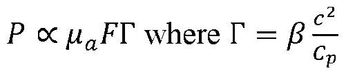
[0121] The simplified pressure equation shows that there are three factors that affect the amount of photoacoustic signal generated. Firstly, the absorption coefficient determines how much light is absorbed by a material, with more absorbent objects producing higher photoacoustic signals. Therefore, when performing photoacoustic imaging, one should select a light w avelength that is highly absorbed by the material of interest to highlight it. Secondly, increasing the optical fluence (F) reaching the object will also increase the generated signal. However, it is important to stay below any damage threshold while using the maximum amount of light permissible. Lastly, the Gruneisen parameter, which is determined by intrinsic mechanical properties of the material, affects the amount of photoacoustic pressure generated. Although these properties cannot be changed, they conveniently vary with temperature. This allows for temperature monitoring using photoacoustic imaging, where different constituents will respond differently during temperature changes. Photoacoustic imaging is thus an ideal monitoring device for applications such as thermal therapy in addition to its spectral imaging capabilities.
[0122] 2. 10.2 Photoacoustic Spectroscopy
[0123] Photoacoustic imaging has a key advantage over other ultrasound imaging modalities, which is its ability to perform spectroscopy. This is because the image contrast in photoacoustics is directly related to the optical absorption of a material, as seen
from the photoacoustic pressure equation. By examining how the photoacoustic image contrast changes over a range of excitation wavelengths, one can attempt to differentiate materials based on their unique absorption spectra.
[0124] A prime example of photoacoustic spectroscopy is its use for blood oxygen saturation measurements. While traditional ultrasound is able to detect large vasculature with the use of Doppler ultrasound, it lacks in its ability to quantify whether that blood is oxygenated or deoxygenated. However, observation of the absorption spectra of hemoglobin and oxygenated-hemoglobin demonstrate significant variations in their absorption spectra..
[0125] Photoacoustic imaging takes advantage of this spectral difference, and is commonly used to differentiate vasculature by taking multiple photoacoustic images at varying wavelengths.
[0126] After acquiring the multi-spectral images, there are various methods available to differentiate materials. These methods can generally be categorized into two groups: those that rely on prior knowledge of each material and those that do not. For a priori analysis, the absorption spectra of known materials are compared with the spectra of each pixel in the image. Cross-validation is then used to segment the image into different constituents. In contrast, blind unmixing techniques aim to sort pixels into groups with similar spectral responses without prior knowledge of the materials. These methods typically use Eigen-decomposition, with principle component and independent component analysis being the most common. However, a disadvantage of blind unmixing is that it cannot specify which segmentation corresponds to which material, which means that user input is required to define each material.
[0127] For biomedical applications, photoacoustic imaging is primarily carried out in the near-infrared region (680 nm - 1000 nm) as this range of light can penetrate deep into the tissue while still generating a detectable photoacoustic signal. When it comes to photoacoustic spectroscopy, imaging at single wavelengths (with a bandwidth of less than 1 nm) is desirable to better resolve the photoacoustic spectrum of the material. As a result, laser systems are mainly used for this purpose. Optical parametric oscillator (OPO) systems are used to access a range of wavelengths. OPO systems use non-linear cry stals to convert a single wavelength pump laser (typically 532 nm) into two different wavelength laser sources, known as the signal and idler. By changing the orientation of the non-linear crystal with respect to the pump laser, the signal and idler wavelengths can be changed. It is worth noting
that the sum of the signal (fs) and idler (fL) frequencies always equals the pump frequency (fp) such that fp = fs + ft.
[0128] 2.10.3 Optical Pulse Considerations
[0129] Just like traditional pulse-echo ultrasound, the duration of the light pulse that generates the photoacoustic signal is a critical factor that influences the properties of the resulting ultrasound wave. As previously explained, the duration of an ultrasound pulse is dictated by its fundamental frequency and is a crucial determinant of the system's resolution. To generate a similar acoustic pulse in photoacoustic imaging, short-pulsed laser light with a duration of less than 50 ns is typically used. This guarantees that the resulting ultrasound wave will fill the bandwidth of the transducer and allow for detection of the generated photoacoustic signal. Because of this, most photoacoustic sources are Q-switched lasers that typically have pulse durations < 5 ns, suitable for any transducer used for photoacoustic applications.
[0130] 2. 10.4 PE/PAT Optical Subsystem
[0131] Based on the fundamentals of photoacoustic imaging that were just discussed, the optical subsystem 104 of the PE/PAT imaging system 100 has been designed with specific considerations in mind. To achieve photoacoustic tomography and imaging of small lesions with our system, it is necessary’ to have an optical subsystem 104 that can provide tunable wavelengths ranging from 680 - 1000 nm, with pulse durations of less than 50 ns. Additionally, the optical subsystem 104 must be extemalty triggerable to enable synchronized PE and PAT, and maintain a compact footprint to ensure mobility of the PE/PAT imaging system 100.
[0132] With these considerations in mind, one embodiment of the optical subsystem 104 incorporates Opotek’s Opolette JE 532 LD Tunable Laser System, which can provide 5 ns pulses over a broad range of wavelengths, where the signal has access to 680 - 1000 nm and idler from 1000 - 2400 nm.
[0133] Integrating our programmable ultrasound system with this optical subsystem for photoacoustic imaging involves certain tradeoffs. While the small size of the laser makes it possible to have a compact and mobile system, the limited power output of the laser can impact the amount of photoacoustic signal generated (average pulse energy’ values around 10 mJ). According to the photoacoustic pressure equation, this can limit the maximum achievable photoacoustic signal. To optimize the amount of optical fluence reaching the target without causing damage, the fluence for soft tissue should not exceed 20 mJ/cm2. Thus, optimizing light delivery' to the tissue through beam shaping can increase the fluence
over a lesion, which can improve image quality. Light delivery and beam shaping will be addressed in the next chapter.
[0134] The integration of the optical subsystem 104 and ultrasound subsystem 102 has enabled both pulse-echo ultrasound and photoacoustic imaging, providing the capability to create a benchtop setup for real-time observation of samples under study. An early experimental setup with these subsystems, which included a third thermoacoustic microwave source, evaluated the contrast mechanisms of each modality and demonstrated the system's ability’ to perform blind unmixing and thermometry.
3. System Design and Assembly
[0135] Now that we have selected our optical and acoustics for the PE/PAT imaging system 100, and discussed the reasons why these selections most suited our needs for the imaging of skin lesions, we can now discuss how the PE/PAT imaging system 100 can be optimized for volumetric imaging. Section 3 outlines methods of illumination design and the challenges faced in achieving highly efficient optical and acoustic transport. We will discuss the design considerations and challenges that were overcome to achieve our illumination method and incorporate our optical and acoustic devices into a single, hand-held device. Furthermore, we will outline how we took this packaged system (incorporating the ultrasound subsystem 102, optical subsystem 104, and optoacoustic coupling subsystem 106) and turned it into a volumetric imaging device with the addition of a linear motor. Along with this, we will discuss how we were able to design the device to allow for easy access and adjustment to anywhere on the patient. We will also discuss our novel method of securely fixing our device to the patient to allow7 for consistent imaging over multiple imaging session. With all of this, we will outline the complex design considerations that went into our device to make it capable of transforming a traditional ultrasound array into a novel volumetric PE/PAT imaging system 100 to be used for assessing cutaneous lesions in a clinical setting.
3.1 Coupling Subsystem
[0136] 3.1.1 Optoacoustic Coupling Methods
[0137] Combining light and sound for photoacoustic imaging systems presents several challenges. One of the primary limitations to optoacoustic coupling is that use of traditional linear arrays requires the transducer to contact the tissue for both transmitting and receiving acoustic w aves. This can make it difficult to integrate a light source into the system,
as the transducer may obscure the photoacoustic light source. To address this challenge, two methods are generally used for coupling light and sound.
[0138] Dark field illumination is a coupling technique that uses optically clear coupling media such as water or ultrasound gel to offset the transducer from the tissue. This allows the photoacoustic light source to be introduced to the system and illuminate the sample with off-axis sources. While this approach provides a simple solution to performing photoacoustics with a linear array, it is limited in terms of image depth, as imaging will only be possible where the optical and ultrasound axes intersect.
[0139] An alternative coupling method utilizes an optoacoustic inline reflector, which aligns the optical and acoustic axes by embedding an acoustic reflector device (which may resemble a glass slide) in the coupling medium captured within the coupling chamber, as shown in FIG. 2. This geometry allows the light to reach the tissue by transmitting through both the coupling medium and the acoustic reflector device. The generated photoacoustic wave is then redirected to the ultrasound transducer by total internal reflection, due to the large disparity in acoustic impedances.
[0140] In our PE/PAT imaging system 100, the limitations of the lower energy laser source discussed in the previous chapter highlight the importance of optimizing the coupling method. The choice of coupling materials and geometry can significantly impact the quality of both photoacoustic images and pulse-echo signals. In this chapter, we will delve into the design considerations for our PE/PAT imaging system 100 to maximize optical fluence and enhance overall image quality through our design choices.
3.2 PE/PAT Coupling Subsystem
[0141] 3.2.2 The Inline Reflector
[0142] For our PE/PAT imaging system 100, we have opted to use an inlinereflector method for light delivery. This is embodied as optoacoustic coupling subsystem 106. This approach offers the best depth penetration and efficient use of our limited light in the tissue. Dark-field illumination is not suitable for skin imaging because off-axis illumination can fail to illuminate objects close to the transducer where light may not reach due to the transducer's location. This is crucial, as the entire lesion must be within the FOV for photoacoustic imaging. The inline adapter design also allows us to optimize light delivery to the tissue. By coaxial alignment of the optical and acoustic axes, we can achieve more refined beam shaping that can enhances optical fluence and depth penetration. We will discuss these methods further in the following section.
[0143] 3.2.2 Optical Beam Shaping
[0144] One of the simplest ways to enhance our photoacoustic signal dictated by the photoacoustic pressure equation presented in the previous chapter is by increasing the optical fluence (F). Optical fluence is the total optical energy over an area and is measured in J/cm2 As we have already selected a low-energy laser source to ensure portability of our PE/PAT imaging system 100, our only option to boost the fluence is to decrease the area where the light illuminates the lesion. This can be achieved through optical beam shaping, which involves using optical elements such as lenses and mirrors to shape the beam to the desired profile. Given that we have coaxially aligned our ultrasound array with our optical path using the inline reflector (e.g., the acoustic reflector device 420), it is best to shape the laser light into a line that matches the ultrasound slice profile as it enters the tissue. This will guarantee that all the available optical energy used to generate a photoacoustic signal is distributed within the FOV of the ultrasound array.
[0145] The laser system (e g., laser source 310 shown in FIG. 3) generates an output via a 0.22 numerical aperture (NA) multimode optical fiber. As we aim to maintain a small system footprint, beam-shaping optics 330 were chosen to include 1/2” lenses 332 for this design. Lens 1's primary purpose is to collimate the light from the optical fiber, allowing lenses 2 and 3 to shape the collimated beam into the desired line profile. The selection of lens 1 must consider two factors. Firstly, the optical subsystem 104 needs to perform over a range of wavelengths (680 - 1000 nm). Single-element lenses suffer from intrinsic chromatic aberrations, so an aspheric achromatic doublet is ideal for effectively collimating the light from the fiber. Secondly, it is optimal to fill the aperture of the lens completely (90% of 1/2” is normal for this lens). Given the lens diameter and known numerical aperture from the fiber, we can calculate the necessary focal length of the achromatic lens (~25 mm). The fiber is positioned at the focal point of Lens 1 to achieve collimation.
[0146] Cylindrical lenses, lens 2 and lens 3, have been chosen to create the desired line profile that matches the ultrasound transducer slice. For our PE/PAT imaging system 100, the L22-14v probe has a minimum slice thickness of 0.5 mm (which will vary depending on the standoff of the transducer from the skin) and a width of 12.5 mm. Lens 2 is selected to focus the line down to the desired slice thickness, providing a positive prescription on one axis, but no optical power at 90°. Conversely, Lens 3's purpose is to ensure that the optical line matches the width of the transducer. Since the collimated beam is less than 12.5 mm, a negative power is necessary along the opposite axis of Lens 2 to widen the line illumination across the sample.
[0147] With these lenses 332, we have developed a method to optimize the amount of photoacoustic signal generated at the tissue surface by shaping the light into a line. By creating a line with a nominal width of -12.5 mm and line height of -0.5 mm to fill the acoustic slice, we expect to significantly increase the optical fluence and thus the photoacoustic signal.
[0148] However, it is important to note that while increasing the optical fluence is desirable, there is a fluence exposure limit to tissue that can cause damage. Therefore, we must ensure that the optical fluence does not exceed 20 mJ cm-2 to prevent any tissue damage. As such, the laser source 310 should have direct electronic control over laser energy, enabling adjustment of the laser energy' of any w avelengths that exhibit unsafe fluence values. In the next chapter, we will further study the laser fluence and optical beam profile of our system, demonstrating how we measure and characterize our system's optical quality.
[0149] 3.2.3 Optoacoustic Coupling Materials
[0150] The choice of coupling medium 430 in the PE/PAT imaging system 100 is crucial as it determines the ability of light to reach the sample while propagating the ultrasound w ave back to the transducer. While benchtop photoacoustic setups like the one outlined in Appendix A often use diH20 or mineral oil due to their minimal optical absorption and scattering, these liquids are not suitable for mobile or probe-based systems as they tend to leak and can contain bubbles that degrade image quality.
[0151] Optically clear gels such as agarose or rubber (i.e. ballistics gel) are preferred for mobile applications as they can be reused multiple times and maintain their structure. However, these rigid materials do not provide both high optical and acoustic clarity. Agarose gels have optical scattering that reduces the amount of light reaching the sample, and can negatively affect the beam profile. Rubbers, on the other hand, have high optical clarity but exhibit high acoustic attenuation, particularly at higher ultrasound frequencies that our system uses.
[0152] Given these limitations, we explored new optical coupling media and found that gellan gum gel is a promising option. Gellan gum is a hydrogel similar to agarose that hydrates with water. After rigorous testing, we found that gellan gum demonstrated improved optical clarity and acoustic attenuation compared to traditional coupling materials such as agarose gel and oil-based rubbers.
[0153] 3.2.4 Comparison of Coupling Materials
[0154] To evaluate the efficacy of gellan gum as a coupling agent for photoacoustic imaging, we conducted a comprehensive analysis of key optical and mechanical properties of gellan gum and compared it to traditional coupling materials such as agarose gel and Humimic Medical Gelatin #0, an optical clear rubber. Additionally, we varied the concentration of gellan gum during gel formation to better understand the gel's behavior. Our primary aim was to evaluate the ability of these gels to transport both light and sound and to determine if the gels' mechanical properties mimicked those of tissue, as this is crucial in preventing Fresnel reflections at tissue/ coupling interfaces.
[0155] To accomplish this, we measured the speed of sound, density, acoustic attenuation, Young's modulus, optical transmission, and photoacoustic signal quality for each material. Our analysis aimed to demonstrate how gellan gum is superior to traditional coupling agents in terms of its optical clarity, acoustic attenuation, and mechanical properties. Additionally, the effects of varying the concentration of gellan gum on its properties were explored. It was found that increasing the concentration of gellan gum resulted in lower speed of sound, density, and lower optical transmission, while the acoustic attenuation coefficient and Young's modulus increased. Therefore, the optimal concentration of gellan gum for photoacoustic imaging applications will depend on the specific requirements of the PE/PAT imaging system 100. Overall, the results suggest that gellan gum is a promising alternative to traditional coupling materials for photoacoustic imaging. Its improved optical clarity and acoustic properties make it a suitable choice for applications requiring both high optical and acoustic performance.
3.3 The Inline Reflector Beyond Photoacoustics
[0156] Our studies on optimizing the inline reflector and improving optoacoustic coupling led us to explore new applications of the inline reflector beyond photoacoustic imaging. Instead of illuminating a sample with light and detecting the resulting sound, we investigated the effects of ultrasound on an object while using optical imaging as a means of feedback. This led to the development of the coupling chamber 410 which embodies an Optoacoustic Window, enabling real-time optical observation during ultrasound stimulation as shown in FIG. 2. This device is particularly relevant for neuromodulation research, as the effects of ultrasound on the brain for traumatic brain injury are not well understood without real-time imaging. Although our studies on the Optoacoustic Window are not directly related to our PE/PAT imaging system 100, they were inspired by our exploration of the inline reflector and are therefore worth noting.
3.4 Integrating Subsystems Preview
[0157] With our plans for light delivery and optimization through beam shaping and choice of coupling medium established, the next step is to integrate these components into a custom 3D printed probe. This will enable us to create a handheld device that can perform real-time PE/PAT imaging for clinical applications. Once the components are packaged, we will focus on achieving volume imaging by adding a linear motor, and exploring how to couple the device to a lesion to prevent movement and improve image quality.
3.5 Packaging Subsystem
[0158] 3.5.1 Packaging Considerations
[0159] The successful packaging of the optics and ultrasound array into a handheld device is a critical step in making our system practical for widespread use in medical settings. However, several mechanical considerations need to be taken into account. The most challenging aspect of this design is the integration of the optical subsystem 104 and ultrasound subsystem 102 with the acoustic reflector device 420 into the probe device 120. In one implementation illustrated in FIG. 3, an effective end of the ultrasound transducer is submerged in the coupling medium (water or gel) for ultrasound wave propagation, while also enabling light to transmit through two optical windows for photoacoustic imaging. In another implementation illustrated in FIGS. 8A-8C, an effective end of the ultrasound transducer can be acoustically coupled with the coupling medium through a coupling membrane (e.g., coupling membrane 1415). Moreover, any optical windows of the coupling chamber 410 that are in contact with the sample must permit the transmission of ultrasound, making the system even more difficult to design as it must be watertight. In addition, we need to ensure precise adjustment of the orientation of the ultrasound probe and optical system to ensure the axes are well aligned.
[0160] Our design also needs optimization for ease of use and patient comfort. Factors such as ergonomics, weight, and portability must be considered to make the device accessible for point-of-care imaging. To achieve this, we will explore the use of 3D printing to create a customized probe that is lightweight and comfortable to use. By accounting for mechanical considerations and optimizing the design for patient comfort, we can make our device accessible for clinical use that meet our system requirements.
[0161] The packaged system includes: the transducer housing 210 associated with the ultrasound subsystem 102, the sliding optical assembly 320 associated with the
optical subsystem 104, and the coupling chamber 410 incorporating the acoustic reflector device 420, shown in FIG. 3. The transducer housing 210 housing captures or otherwise engages the ultrasound transducer 220, optical fiber input, and a collimating lens. The sliding optical housing contains the beam-shaping optics 330 of the optical subsystem 104 including cylindrical line optics and folding mirror. The coupling chamber 410 incorporating the acoustic reflector device 420 integrates both ultrasound and light within a fully contained system.
[0162] In this chapter, we will outline each of these components and their significance in the probe design as a whole. We will also discuss the design considerations that were taken into account for each component, such as the need for water-tightness and alignment accuracy.
[0163] 3.5.2 The Transducer housing (for L22-14v transducer)
[0164] a) Transducer 3D Design
[0165] During the process of designing the transducer housing 210 for one embodiment of the ultrasound transducer 220 (e.g., the L22-14v transducer), one of the significant challenges was the absence of a proper 3D object design for the ultrasound transducer 220, which made it impossible to create a 3D housing with a negative cavity that fits perfectly with the probe. This was particularly important for making a waterproof part. To overcome this challenge, we created a model of the probe using caliper measurements and radii values. The most crucial parameters of the probe were its maximum width and height, which measured 34 mm and 25 mm, respectively.
[0166] Based on these geometric constraints, we determined that to ensure a minimum 2 mm wall thickness encompassing the ultrasound transducer 220, the transducer housing 210 should be no less than approximately 38 mm x 29 mm. Using this model of the probe, we were able to design a housing that would work for a probe similar to the L22 without requiring exact geometries. This approach allowed us to create a transducer housing 210 that fits the ultrasound transducer 220 appropriately while meeting our requirements for a waterproof part.
[0167] b) Transducer Mounting (for L22-14v transducer)
[0168] The transducer housing 210 for one embodiment of the ultrasound subsystem 102, ensures that the effective end of the ultrasound transducer 220 extends beyond the boundaries of transducer housing 210 so that it could be inserted into the coupling chamber 410 and be submerged in water or gel for acoustic transport. This was achieved by using four set screws to apply axial force along the probe placed at the tail of the transducer
to secure it against a square, undersized aperture. Upon inserting the ultrasound transducer 220 into the transducer housing 210. the screws can be tightened to securely lock the transducer in place. One advantage to this mounting method is that it provides a means of rotational adjustment by tightening or loosening apposing screws, allowing for adjustment to the probe's orientation.
[0169] It is important to note that the aperture where the face of the ultrasound transducer 220 rests on is slightly undersized and does not conform completely to the shape of the effective end of the ultrasound transducer 220. Instead, the ultrasound transducer 220 is seated on beveled straight edges both laterally and vertically, serving as pivot points for the ultrasound transducer 220 to rotate around. This seating method allows for both vertical and lateral rotation while preventing any axial rotation around the ultrasound transducer 220. This method ensures that the acoustic slice remains parallel to the entrance and exit apertures of the inline reflector, thereby maintaining the desired imaging quality.
[0170] c) Optical Mounting
[0171] To reduce the size of our packaged probe, the light signal generated by the optical subsystem 104 can be folded using mirror 334. This enables the optical subsystem 104 to be mounted parallel to the ultrasound transducer 220 (or ultrasound transducer 1220).
The optical subsystem can be broken up into two components to enable alignment of the optical and acoustic axes with the sliding optical assembly 320 (discussed in the next section). The transducer housing 210 incorporates the fiber input and collimating lens of the optical subsystem 104 and is placed above the ultrasound transducer 220 in a fully enclosed lens tube. The optical fiber was mounted using a pre-threaded SubMiniature Version A (SMA) fiber mount, which was locked into place with a nut. To maintain the required spacing between the fiber and collimating lens, a 3D spacer was printed (a cylindrical, hollow tube) for the lens to rest against. To secure the lens, a single compression set screw is threaded through the housing that applies lateral force against the lens.
[0172] When mounting the lenses 332. it is crucial to ensure proper alignment between the fiber and the optical piece. In the case of these lenses, a significant consideration is the alignment of the optical axis, as the mounting method of the lens forces it to be in contact with the lower wall of the lens tube. This results in the optical axis being offset from the center of the lens tube by the difference in size between the tube and the lens.
[0173] To address this issue, an offset was included in the SMA mounting hole and lens tube to account for the shift caused by the contact between the lens and the lower wall of the tube. This offset ensures that all optical pieces are well-aligned and the
desired imaging quality is achieved. It is important to pay close attention to alignment during the lens mounting process to prevent any potential issues that could affect the performance of the PE/PAT imaging system 100.
[0174] d) Waterproofing the Transducer
[0175] To enhance the waterproofing of the transducer housing 210, a raised lip was included around the ultrasound transducer 220 to fit into a corresponding groove on the coupling chamber 410 of the optoacoustic coupling subsystem 106. This sealing method allows for watertight coupling if manufactured with tight tolerancing when printed. Petroleum jelly can be applied within the groove and flat surfaces to further improve the seal when combined with the inline reflector. In addition, petroleum jelly can be used to fill any gaps that occur between the transducer and undersized aperture on which it is seated. It is challenging to prevent such gaps without exact geometries of the transducer, one of the reasons why the rectangular aperture was selected. Tightly mounting the transducer housing to the inline reflector with the use of screws ensures a watertight seal.
[0176] Note that for the transducer housing 1210 and coupling chamber 1410 of FIGS. 8A-8C, it is not necessary to waterproof the ultrasound transducer 1220 as the coupling chamber 1410 includes the coupling membrane 1415 as shown, which acoustically couples the ultrasound transducer with the coupling media within the coupling chamber 1410 without needing to submerge the ultrasound transducer 1220 in the coupling media.
[0177] e) Transducer Mounting Considerations
[0178] The design of the transducer housing 210 aimed to optimize the standoff distance (see FIG. 10C) between the ultrasound transducer 220 and tissue, as this distance has a direct impact on the lateral resolution of the system. Specifically, an increased standoff distance results in a higher F# of the system, which in turn reduces the lateral resolution. To minimize the standoff distance, we initially considered adding a second ultrasound reflection to the design so that the ultrasound transducer 220 and beam-shaping optics 330 could remain vertical like a traditional ultrasound probe. However, due to geometric constraints imposed by the probe size, this design was found to be suboptimal. The addition of a second acoustic reflection increased the F# to a level where the lateral resolution was far larger than our system requirements (F# ~ 3 lateral resolution > 350 pm). As a result, the design which utilizes a single acoustic reflection implemented by the acoustic reflector device 420, was chosen instead.
[0179] While the single reflection design maintains our high resolution imaging capabilities, it does have some limitations in terms of probe placement. Specifically,
this design choice increases the overall footprint of the probe that will be in direct contact with the tissue, making it more difficult to reach certain locations of the body and potentially impeding or blocking transducer placement. However, given an imaging goal of skin lesions, achieving high-quality images is important, and this design represents a necessary tradeoff to achieve that goal.
[0180] 3.5.3 The Sliding Optical Assembly
[0181] The sliding optical assembly 320 was designed to allow for fine adjustments to the optical axis, independent of the collimating lens and fiber port. The ability to slide the beam-shaping optics 330 including the cylindrical lens and mirror enables lateral movement of the optical axis, ensuring alignment with the acoustic axis with minimal impact on the beam profile. Although ideally, a 3D printed system would be fully aligned upon assembly, low tolerancing and manufacturing error necessitate the ability to adjust the location of the line illumination to compensate for any imperfections in manufacturing or alignment. The mounting methods for the beam-shaping optics 330 were the same as for the collimating lens: setscrews were used to secure the cylindrical lenses in the optical tube, and the mirror was secured in its designated slot using the same method. To allow for both mounting and sliding, the 3D design included a rail sliding system with setscrews to lock the system in place once aligned.
[0182] 3.5.4 The Coupling Chamber
[0183] a) Coupling Chamber: The Embedded Glass
[0184] The coupling chamber 410 (inline reflector) presented the most complex design challenge in the packaging system due to the need to integrate both light and sound in coupling medium. The coupling chamber 410 is essentially a cube (or rectangular prism) of coupling medium with the acoustic reflector device 420 (resembling a glass slide) embedded at a 45° angle to reflect the acoustic signal towards the output window 416. For one embodiment, we incorporated 1 mm lips that allow for a custom-cut glass slide to sit on, and we secured it in place using a simple 5-minute epoxy adhesive.
[0185] b) Coupling Chamber: Optical Windows
[0186] The top and bottom of the coupling chamber 410 require optical windows (e.g., optical input window 412 and output window 416) to allow for the transmission of light, where the output w indow 416 must also transmit sound. For our purposes, we found that cling film could be used as part of a simple yet effective optoacoustic window. Cling film provides a clear and thin barrier that keeps coupling media wi thin the coupling chamber 410 without significantly affecting the beam profile or generated
ultrasound. To ensure that the cling film was taut and free of wrinkles, a window frame was designed to hold it in place. The window frame was designed to fit snugly within the coupling chamber 410, which prevented water from leaking in or out.
[0187] c) Coupling Chamber: Mounting
[0188] To mount the transducer housing 210 to the coupling chamber 410, screw mounts were added to securely fasten the two pieces together. Petroleum jelly was applied around the seam to ensure a watertight seal between the pieces. The sliding optical assembly 320 was integrated by adding a corresponding rail system to the top of the coupling chamber 410. This enabled adjustments to be made for co-alignment of the optics, which could then be locked in place with a set screw.
[0189] d) Filling the Coupling Chamber
[0190] In order to fill the coupling chamber 410 with coupling media such as water or gel, a fill hole was added towards the front face of the coupling chamber 410. Due to the tight tolerancing of the hole and plug, the coupling chamber 410 is able to maintain its integrity, where petroleum jelly can be used to further ensure its water-tightness.
[0191] 3.5.5 Packaging Subsystem Summary
[0192] With the successful integration of the various components of the photoacoustic probe, a major milestone has been achieved in the development of a portable, hand-held clinical-ready device. The improved alignment between the optical and acoustic axes has resulted in higher quality images and improved clinical utility. However, the ability to perform volumetric scanning is desirable. To address this, the next step is to incorporate the volumetric scanning subsystem 108 which includes a linear motor for elevation scanning and optimize the scanning methods to achieve the best possible images. Additional components and design changes to the packaged system will also need to be incorporated into the device.
3.6 Scanning Subsystem
[0193] 3.6. 1 Volume Imaging Considerations
[0194] To convert a linear ultrasound transducer such as ultrasound transducer 220 or ultrasound transducer 1220 into a volumetric imaging system, a precise scanning mechanism is required. In the PE/PAT imaging system 100, the volumetric scanning subsystem 108 includes a programmable precision linear motor (e.g., volumetric scanning motor 520). To meet the system requirement of imaging a 1.0 cm3 volume, the motor must travel at least 1.0 cm. However, incorporating the volumetric scanning motor 520 requires a
new mounting method to allow the ultrasound transducer to slide independently across a tissue sample from the motor housing. We have addressed this by mounting the motor housing 514 on an articulating arm, which allows for hands-free placement of the probe on the lesion, making it more convenient for clinical use.
[0195] This chapter will explore the scanning requirements necessary for our PE/PAT imaging system 100, including step size and accuracy, and how they affect voxel resolution and image quality. We will also discuss the limitations introduced by the packaging subsystem and how the elevational slice thickness of the ultrasound transducer plays an important role in the resolution of our system. By examining these factors, we aim to optimize the scanning system to ensure the highest possible voxel resolution and image quality for our PE/PAT imaging system 100.
[0196] 3.6.2 Volume Resolution & Elevational Dependence
[0197] In the scanning process of the ultrasound system, the elevational slice thickness of the transducer incident on the tissue is a crucial factor in volume resolution. As described above with respect to the ultrasound subsystem 102, the acoustic lens used in the transducer determines the elevational slice thickness, with the smallest slice thickness being achieved in the focal region. A side profde of the ultrasound plane in FIG. 10A demonstrates how the slice thickness changes with depth. A standard PE/PAT acquisition includes all the structures within this slice.
[0198] During volume imaging, the ultrasound transducer is moved perpendicular to the slice to generate a stack of images, as shown in FIGS. 11 A and 1 IB. The ability to distinguish two individual objects along this axis is dependent on the slice thickness at the object location and the displacement between each image. Higher resolution requires thinner slice thicknesses and more sampling steps, making it ideal to place the tissue as close to the focal zone as possible, as depicted in FIGS. 10A and 12.
[0199] For our PE/PAT ultrasound subsystem, the L22-14v probe (e.g., the ultrasound transducer 220) has an elevational focus of 8. 1 mm, making it the ideal standoff distance for the transducer. However, due to geometrical constraints imposed by our packaged system the including coupling chamber 410, it was necessary to increase the standoff distance beyond this (~15 mm). The height of the ultrasound transducer requires the acoustic path to be greater than or equal to half the width of the ultrasound transducer and was therefore the most significant limiting geometric constraint, as shown in FIG. 10C.
[0200] As the ultrasound transducers half-height is roughly double the elevational focus and the F# of the acoustic lens, we can expect the elevational thickness to
be ~ 1000 mm. Methods of determining our packaged systems slice thickness at the tissue (i. e. , estimated scanning resolution) and the necessary motor step sizes are discussed in Appendix X.
[0201] 3.6.3 PE/PAT Scanning Subsystem Design
[0202] a) Motor Selection
[0203] Careful consideration went into the selection of the volumetric scanning motor 520 used for our PE/PAT imaging system 100. We required a motor that was capable of linear motion with a range greater than 10 mm that we could programmatically scan to specific locations with a precision of < 10 pm. With these specifications in mind, one embodiment uses a Zaber NA11B30-T4A linear actuator. This linear actuator is capable of pushing/pulling the packaged system across the tissue at increments as small as 0.01 pm over a 30 mm range.
[0204] b) Integration of the Motor
[0205] In order to integrate the volumetric scanning motor 520, it was necessary’ for the probe device 120 (e.g., the combined ultrasound subsystem 102, optical subsystem 104 and optoacoustic coupling subsystem 106) to move independently from the volumetric scanning motor 520 and its motor housing 514. To achieve this, the linear bearings 530 are integrated into the probe mounting rails 512 (and/or the transducer housing 210), as depicted in FIGS. 4A and 8A. These linear bearings 530 function by enabling the packaged system to smoothly slide on two parallel rods that are part of the motor housing 514.
[0206] Furthermore, we needed to attach the volumetric scanning motor 520 to the packaged system. Since the volumetric scanning motor 520 is a linear rod designed to push the system, we positioned it directly above the probe and secured it to the probe mounting rails 512 (which can be engaged with or otherwise associated with the transducer housing 210 and/or the the sliding optical assembly 320). This configuration reduces the overall footprint of the packaged system w hile enabling the motor housing 514 to be connected to an articulating arm for clinical use. FIGS. 4C-4E show the probe device 120 with the volumetric scanning motor 520, including motion of the probe device 120 relative to the volumetric scanning motor 520.
[0207] 3.6.4 Scanning Subsystem Summary’
[0208] With the integration of the volumetric scanning motor 520, the packaged system possesses the capability to acquire multiple PE/PAT acquisitions across a range of locations to facilitate volumetric imaging. Furthermore, the motor housing 514
enables the PE/PAT imaging system 100 to be mounted on an articulating arm, significantly enhancing its practicality for clinical applications.
[0209] However, there is a significant challenge remaining, which is how to secure the device to the tissue. To obtain a proper image of a lesion using the PE/PAT imaging system 100, it is crucial to ensure that the lesion or probe remains immobile throughout the duration of the scan. This is particularly vital for volume imaging, where the transducer must traverse the tissue to produce the volume. Thus, we must devise a mechanism to fix the device securely to the tissue to ensure optimal image quality.
3. 7 Tissue Coupling Subsystem
[0210] 3.7. 1 Novel Tissue Coupling
[0211] Traditional ultrasound imaging systems use hand-held linear transducers, which can result in variable image quality due to the operator's skill level and the probe's position and orientation relative to the tissue being imaged. This user-dependent variability7 can lead to inaccuracies when comparing images from different time points or locations, potentially impacting patient health through misdiagnosis or suboptimal treatment decisions. These inaccuracies also make it difficult to monitor temporal changes of a lesion over multiple imaging sessions, as misalignment between sessions can skew results. Consequently, the inability to acquire consistent data sets prevents the use of certain monitoring techniques that rely on consistent image views, such as machine learning analysis. Such methods are ideal candidates for monitoring skin lesions and could be extremely advantageous if the images' consistency could be ensured.
[0212] Given that our PE/PAT imaging system 100 will be scanning over a volume for an extended duration of time, it is critical to prevent any image degradation from user or patient movement. To address this challenge, we have developed a magnetic coupling method that secures our PE/PAT imaging system 100 to the tissue, allowing for hands-free imaging by the clinician. This novel tissue coupling method enables accurate and reproducible imaging, enhancing diagnostic and treatment decision-making while also improving clinical usability.
[0213] In this chapter, we will briefly describe the challenges we encountered in developing our coupling method and the modifications we made to our packaged system to implement this approach effectively.
[0214] 3.7.2 Coupling Considerations & Limitations
[0215] Our aim was to develop the tissue coupling subsystem 110 that could securely fix the PE/PAT imaging system 100 to the tissue during imaging while still allowing patients to move away from the system if necessary. To achieve this, the present disclosure outlines a novel magnetic coupling method using a washer-like coupler element (coupler element 620 show n in FIG. 6) that w ould surround the lesion and attach to the tissue using double-sided tape. The coupler element can be paramagnetic, ferromagnetic, or otherwise magnetically permeable such that the coupler element is magnetically attracted to the magnet 616. The PE/PAT imaging system 100 could then magnetically lock onto the w asher for stable imaging, enabling accurate and reproducible imaging for diagnostic and treatment purposes.
[0216] To incorporate this magnetic coupling method into our system, we had to consider various mechanical constraints. It was necessary for the probe 120 to slide across the tissue independently of the motor, which required integrating the magnetic coupling with the motor housing. We designed the receiver plate 610 to include the aperture 612, the recess 614 around the aperture, and the embedded magnet(a) 612 to prevent lateral motion between the tissue/lesion and the probe, while still allowing the probe and patient to be separated with minimal normal force. These design concepts are illustrated in FIGS. 5A-5D.
[0217] When integrating the tissue coupling subsystem 110 into the imaging system 100, we had to ensure that the standoff distance between the transducer and tissue was not increased to prevent any negative impact on imaging resolution. Therefore, we made modifications to the packaged system to accommodate the 4 mm coupling device while maintaining the original standoff distance. To achieve this, we reduced the wall thickness of the coupling chamber 410, which allowed the transducer to slide across the tissue linearly. This modification allowed for accurate and reproducible imaging while using the tissue coupling subsystem 110.
[0218] Along with integrating the tissue coupling subsystem 110 into the motor housing, we also wanted to improve the usability of our system for clinicians byadding ergonomic features such as handles. However, we had to ensure that the addition of the tissue coupling subsystem 110 and handles did not limit the clinician's ability to access different areas of the body during imaging. To address these needs, we added two cylindrical handles to the motor housing 514, located adjacent to the articulating arm mount, as shown in FIGS. 7A and 7B, as well as FIGS. 9A and 9B.
[0219] With these handles in place, we could attach the coupling subsystem to the handles to secure it to the motor housing, providing an effective method of allowing the packaged transducer to move independently from the rest of the system.
3.8 Laser Safety Mechanism
[0220] As our PE/PAT imaging system 100 utilizes a short-pulsed, high- power laser, it is crucial that we consider the potential hazards associated with this type of light. To ensure a safe clinical environment for both patients and clinicians, it is essential that the laser remains fully shrouded during its propagation from the laser to the tissue. Our novel tissue coupling method guarantees that the laser remains contained when our washer is magnetically sealed to the probe. However, as our coupling method allows for patients to move away from the probe, we need to incorporate an interlock feature in our device to turn off the laser automatically if the probe becomes separated from the patient.
[0221] To achieve this, we have integrated a photosensitive circuit into the coupling part of the packaged system. This interlock circuit includes a photoresistor, an LED strip, a relay switch, and an Arduino for logic. The circuit operates by sensing the ambient light close to the optoacoustic window of the probe. When the probe is coupled to the tissue, the photoresistor is obscured, increasing the resistance and lowering the voltage reading on the Arduino. However, if the probe becomes decoupled, the ambient light causes the voltage to rise and once it surpasses a predetermined threshold voltage, the Arduino activates the relay to trigger the laser interlock. The additional LED strip guarantees that the interlock is triggered once the probe is decoupled, as the light from the LEDs will reflect off the tissue and onto the photoresistor.
3.9 System Summary
[0222] With the successful addition of the tissue coupling subsystem 110, our imaging device is now capable of volumetric pulse-echo ultrasound and photoacoustic tomography for clinical use. The design choices for the optical and acoustic systems were made with great care to achieve the desired high resolution imaging (<250 pm) with our device. We also considered the packaging constraints and made appropriate material and design choices to integrate all the subsystems. These efforts should allow our device to perform exceptionally for the clinical assessment of suspicious skin lesions.
4. Computing System
[0223] FIG. 13 is a schematic block diagram of an example computing device 700 that may be used with one or more embodiments described herein, e.g., as a component of the imaging system 100 (or 1000) shown in FIGS. 1-12.
[0224] Computing device 700 comprises one or more network interfaces 710 (e.g., wired, wireless, PLC, etc.), at least one processor 720, and a memory 740 interconnected by a system bus 750, as well as a power supply 760 (e.g., battery, plug-in, etc.). Further, computing device 700 can include or otherwise communicate with a display device 730 for real-time (or post-imaging) visualization and display.
[0225] Network interface(s) 710 include the mechanical, electrical, and signaling circuitry for communicating data over the communication links coupled to a communication network. Network interfaces 710 are configured to transmit and/or receive data using a variety of different communication protocols. As illustrated, the box representing network interfaces 710 is shown for simplicity, and it is appreciated that such interfaces may represent different types of network connections such as wireless and wired (physical) connections. Network interfaces 710 are shown separately from power supply 760, however it is appreciated that the interfaces that support PLC protocols may communicate through power supply 760 and/or may be an integral component coupled to pow er supply 760.
[0226] Memory' 740 includes a plurality of storage locations that are addressable by processor 720 and network interfaces 710 for storing software programs and data structures associated with the embodiments described herein. In some embodiments, device 700 may have limited memory or no memory (e.g., no memory for storage other than for programs/processes operating on the device and associated caches). Memory 740 can include instructions executable by the processor 720 that, when executed by the processor 720, cause the processor 720 to implement aspects of the imaging system and the methods outlined herein.
[0227] Processor 720 comprises hardw are elements or logic adapted to execute the software programs (e.g.. instructions) and manipulate data structures 745. An operating system 742, portions of which are typically resident in memory 740 and executed by the processor, functionally organizes device 700 by, inter alia, invoking operations in support of software processes and/or services executing on the device. These softw are processes and/or services may include PE/PAT imaging processes/services 790, which can include aspects of methods and/or implementations of various modules described herein. Note that while PE/PAT imaging processes/services 790 is illustrated in centralized memory'
740, alternative embodiments provide for the process to be operated within the network interfaces 710, such as a component of a MAC layer, and/or as part of a distributed computing network environment.
[0228] It will be apparent to those skilled in the art that other processor and memory types, including various computer-readable media, may be used to store and execute program instructions pertaining to the techniques described herein. Also, while the description illustrates various processes, it is expressly contemplated that various processes may be embodied as modules or engines configured to operate in accordance with the techniques herein (e.g., according to the functionality of a similar process). In this context, the term module and engine may be interchangeable. In general, the term module or engine refers to model or an organization of interrelated software components/functions. Further, while the PE/PAT imaging processes/services 790 is shown as a standalone process, those skilled in the art will appreciate that this process may be executed as a routine or module within other processes.
[0229] In some examples, the PE/PAT imaging processes/services 790 can include instructions executable by the processor 720 to: apply the ultrasound signal and the light signal to the target tissue area; receive a return ultrasound signal and a return light signal from the target tissue area; and construct, based on the return ultrasound signal and the return light signal, one or more cross-sectional images of the target tissue area. For volumetric scanning, the PE/PAT imaging processes/services 790 can further include instructions executable by the processor 720 to: apply one or more actuation signals to the motor of the scanning subsystem to actuate the probe device along the linear axis associated with a tissue surface; construct, based on the return ultrasound signal and the return light signal, a plurality of cross-sectional images of the target tissue area; and construct a volumetric image of the target tissue area using the plurality of cross-sectional images.
[0230] The PE/PAT imaging processes/services 790 can include instructions executable by the processor 720 to: apply a Doppler ultrasound signal to the target tissue area; and receive a return Doppler ultrasound signal from the target tissue area. Alternatively or in addition, the PE/PAT imaging processes/services 790 can include instructions executable by the processor 720 to: apply an elastographic ultrasound signal (e.g., a “shear wave”) to the target tissue area to the target tissue area; and receive a return elastographic ultrasound signal from the target tissue area. The light signal can be a pulsed or modulated light signal. The light signal can be near-infrared, short wave, or can be from other portions of the electromagnetic spectrum.
5. Discussion
[0231] FIGS. 14A-14E demonstrate reproducibility of data generated by the PE/PAT imaging system 100/1000, which is enabled by the tissue coupling subsystem 110 shown in FIGS. 5A-7B. As illustrated in FIGS. 14A-14C. atest structure 10 was created which included a tube structure having a plurality of wires 12. In the example implementation shown, the tube structure was filled with agarose gel. A coupler element 620 was positioned along a top of the test structure 10 as shown in FIG. 14C, and subjected to imaging by the PE/PAT imaging system 100/1000 as shown in FIG. 14A. Note that while the imaging system shown in FIG. 14A is the PE/PAT imaging system 100 of FIGS. 1-7B, the PE/PAT imaging system 100 of FIGS. 8A-9B can be used as well.
[0232] FIGS. 14D and 14C show' depth (Z) vs lateral (x) PA cross-sectional images taken fifteen days apart using the PE/PAT imaging system 100/1000 that feature the test structure 10 with the plurality of wires 12 acting as guide or calibration points. Crosscorrelation between the two images was found to be R=0.8013. Because the tissue coupling subsystem 110 removably coupled the same portion of the test structure 10 to the PE/PAT imaging system 100/1000, substantially similar images of the same cross-sectional area were acquired on two different dates. This demonstrates that the PE/PAT imaging system 100/1000 having the tissue coupling subsystem 110 can “lock on” to the same area within a target structure to generate reproducible data.
[0233] In addition, because the tissue coupling subsystem 110 allows the PE/PAT imaging system 100/1000 to “lock on” to the same area within a target structure using magnetic structures, a practitioner can consistently capture the same areas for imaging without manually holding the PE/PAT imaging system 100/1000 at the same area within a target structure.
[0234] This further indicates that volumetric data captured by combining a plurality of cross-sections can be similarly reproducible using the PE/PAT imaging system 100/1000 having the tissue coupling subsystem 110. The volumetric scanning subsystem 108 can actuate the probe device 120 relative to a target structure while the tissue coupling subsy stem 110 maintains the target structure at a constant position.
[0235] Throughout this disclosure, the PE/PAT imaging system 100/1000 has been demonstrated to be a promising new clinical device that is now ready to be used for studying suspicious lesions in a clinical setting. High-quality pulse-echo and photoacoustic images have been produced with excellent resolution, contrast, and depth penetration, making
it a valuable tool for clinicians to assess lesions non-invasively without the need for ionizing radiation or contrast agents. Importantly, the PE/PAT imaging system 100 enables repeatable, reproducible, and longitudinal imaging across the same region of interest in five dimensions (volume, time, optical wavelength/spectroscopy).
[0236] Key design considerations that went into making the device were highlighted, including the optimization of the integration of optical and acoustic systems into a custom, 3D printed hand-held device that is water-tight, highly efficient in optical and acoustic transmission, and prioritizes image quality and resolution in a compact system. The addition of a linear scanning motor allowed the acquisition of volume pulse-echo and photoacoustic images for the first time, and a novel tissue coupling method enabled handsfree imaging by the clinician and re-imaging of the lesion over multiple sessions. The system was characterized, and its capabilities were demonstrated through a promising pilot study.
[0237] Efforts were made to make the system accessible and easy to use for clinicians, with an ergonomic and user-friendly design that could easily couple to a patient and allow for hands-free imaging of lesions. The data acquisition and processing pipelines were streamlined, minimizing the need for manual intervention and reducing the time required to obtain images, and simple user interfaces were created to enable clinicians to perform imaging sessions with relative ease. Moving forward, several directions should be taken to further improve the system's capabilities and expand its potential applications. Immediate work should focus on adding and improving upon the spectroscopic capabilities of the PE/PAT imaging system 100.
[0238] While the PE/PAT imaging system 100 has the necessary' spectral range for spectroscopy, the ability to positively identify things such as melanin content, vasculature mapping, blood oxygen levels, or lipid/collagen content with high specificity and accuracy would be an extremely useful tool for clinicians. The system is currently able to provide the data necessary for this identification, now the research into how this could be implemented by identifying the critical wavelengths needed and the complex unmixing methods required to do this must now be studied.
[0239] Additionally, current research should focus on continuing imaging of all ty pes of lesions in order to build up a large database of a variety of lesions. This will enable expanding the spectroscopic capabilities of the PE/PAT imaging system 100 by crossvalidating results. This would further enable research into potential unmixing techniques that rely on machine learning, where these data sets could be used for training to identify the key wavelengths and highlight materials found within the tissue. Machine learning may be used to
recognize features found within different types of lesions that could be used to help the clinician with diagnostics and guide in therapy.
[0240] Changes to the mechanical design of the PE/PAT imaging system 100 can also continue to be improved and updated during this process. There are several areas that can use further refinement to improve image quality and make the system more accessible. One such area that has potential benefit would be expanding the system's spectral capabilities. By extending the system's spectral range to the short-wave infrared (1000 nm - 2000 nm). we can image lipids, water, and collagen, which offer valuable insights into suspicious skin lesions. This could potentially enable to more accurate and reliable i den ti fi cation of the presence and distribution of suspicious cells, leading to more precise diagnoses and better patient outcomes.
[0241] In addition, selection of a different linear array may be suitable for improved performance. Elevational resolution of the system is not optimal for the type of features that are desirable to resolve, where measured resolution was on the order of 1 mm. While acceptable for some applications, features could potentially be missed with such low resolution. Additional research should be done to explore other commercial linear arrays that could be used with the Verasonics system that possess longer focus and lower acoustic lens F# for thinner slice thickness. One potential candidate for this is a Philips CL 1 -7 shown with respect to FIGS. 8A-9B. This transducer, while having a lower center frequency at 12 MHz compared to our current transducers 18 MHz, possesses a elevational focus at 15 mm, and has a lower F# for both axial and elevational effectively maintaining the same lateral resolution but possess a slice thickness of ~ 100 pm making it an ideal candidate for future research.
[0242] Utilization of a laser with a faster pulse rate could also significantly enhance performance of the PE/PAT imaging system 100. The current laser system's maximum firing rate is 20 Hz, limiting the system's frame rate, as image reconstruction requires two pulses per frame. As a result, the current PE/PAT frame rate is limited to 10 Hz, and current scan times of approximately 5 minutes could be substantially reduced if this w ere to be increased. Moreover, the current laser system is unable to change wavelengths quickly, further increasing acquisition time. However, reducing the time taken to change wavelengths could mitigate this limitation.
[0243] Finally, ongoing research is exploring the potential for 3D volume imaging without the need to translate the transducer across the tissue. This innovation could potentially revolutionize how ultrasound 3D imaging is performed by eliminating inaccuracies that arise from mechanical motion of the probe moving across the skin. Additionally, it could decrease imaging time, increase volume resolution, and simplify the
imaging process for clinicians. However, significant further work is required before this technology can be implemented in the system, as our current designs are still undergoing initial testing stages to demonstrate proof of concept.
[0244] It should be understood from the foregoing that, while particular embodiments have been illustrated and described, various modifications can be made thereto without departing from the spirit and scope of the invention as will be apparent to those skilled in the art. Such changes and modifications are within the scope and teachings of this invention as defined in the claims appended hereto.
Claims
1. An imaging system for hybrid pulse-echo (PE) photoacoustic tomography (PAT) imaging with linear scanning and minimized system movement, comprising: a probe device, including: an ultrasound device operable for detecting and processing acoustic signals including a transducer for generating an ultrasound signal, an optical subsystem operable for generating a light signal for application to a target tissue area, and an optoacoustic coupling subsystem that integrates the light signal and the acoustic signals into a coaligned axis to accommodate transmission of light to the target tissue area and generation of ultrasound back to the ultrasound device; a scanning subsystem including a motor and a housing for the motor, the motor mechanically engaged with the probe device to actuate the probe device along a linear axis associated with a surface of the target tissue area for volumetric scanning; and a tissue coupling subsystem including a receiver plate positioned along the scanning subsystem, the receiver plate being operable to magnetically interface with a tissue coupler positionable around the target tissue area to allow for hands-free operation and improve reproducibility7 of data generated by the imaging sy stem.
2. The imaging system of claim 1, further comprising: an articulating arm of the scanning subsystem, the housing of the scanning subsystem integrated onto the articulating arm to accommodate easier adjustment of the probe device along the target tissue area.
3. The imaging system of claim 1, wherein the housing of the scanning subsystem includes one or more linear bearings to accommodate smooth movement of the housing and the probe device along parallel rods that are part of the housing.
4. The imaging system of claim 1, wherein the motor of the scanning subsystem is a single-direction programmable linear motor that mechanically drives the probe device along the linear axis associated with a surface of the target tissue area.
5. The imaging system of claim 1, wherein the motor is positioned over the probe device to reduce an overall footprint of the imaging system.
6. The imaging system of claim 2, wherein the housing includes handles defined adjacent to the articulating arm to improve ergonomic usability, the handles are configured to engage with the optoacoustic coupling subsystem.
7. The imaging system of claim 1, wherein the tissue coupler includes a paramagnetic or ferromagnetic washer that magnetically locks with the receiver plate.
8. The imaging system of claim 1, wherein the receiver plate includes a recessed cutout and an embedded magnet that magnetically locks with the tissue coupler and reduces lateral motion between the target tissue area and the probe device.
9. The imaging system of claim 1, wherein the optical subsystem can tune the light signal to a predetermined portion of an electromagnetic spectrum defining a predetermined wavelength.
10. The imaging system of claim 1, further comprising: a computing device including a processor in communication with a memory’, the memory' including instructions executable by the processor to: apply the ultrasound signal and the light signal to the target tissue area; receive a return ultrasound signal and a return light signal from the target tissue area; and construct, based on the return ultrasound signal and the return light signal, one or more cross-sectional images of the target tissue area.
11. The imaging system of claim 10. the memory further including instructions executable by the processor to:
apply one or more actuation signals to the motor of the scanning subsystem to actuate the probe device along the linear axis associated with a tissue surface; and construct, based on the return ultrasound signal and the return light signal, a plurality of cross-sectional images of the target tissue area.
12. The imaging system of claim 11. the memory further including instructions executable by the processor to: construct a volumetric image of the target tissue area using the plurality' of cross- sectional images.
13. The imaging system of claim 11, the memory further including instructions executable by the processor to: apply a Doppler ultrasound signal to the target tissue area: and receive a return Doppler ultrasound signal from the target tissue area.
14. The imaging system of claim 11, the memory further including instructions executable by the processor to: apply an elastographic ultrasound signal to the target tissue area; and receive a return elastographic ultrasound signal from the target tissue area.
15. The imaging system of claim 1, wherein the tight signal is a pulsed or modulated near-infrared tight signal.
Applications Claiming Priority (2)
| Application Number | Priority Date | Filing Date | Title |
|---|---|---|---|
| US202363503425P | 2023-05-19 | 2023-05-19 | |
| US63/503,425 | 2023-05-19 |
Publications (1)
| Publication Number | Publication Date |
|---|---|
| WO2024243159A1 true WO2024243159A1 (en) | 2024-11-28 |
Family
ID=93590273
Family Applications (1)
| Application Number | Title | Priority Date | Filing Date |
|---|---|---|---|
| PCT/US2024/030274 Ceased WO2024243159A1 (en) | 2023-05-19 | 2024-05-20 | Systems and methods for closed-loop ultrasound and photoacoustic imaging |
Country Status (1)
| Country | Link |
|---|---|
| WO (1) | WO2024243159A1 (en) |
Cited By (1)
| Publication number | Priority date | Publication date | Assignee | Title |
|---|---|---|---|---|
| CN119861043A (en) * | 2024-12-27 | 2025-04-22 | 长沙理工大学 | Method and platform for characterization of drug sensitivity characteristics of unmarked organoids based on photoacoustic imaging |
Citations (7)
| Publication number | Priority date | Publication date | Assignee | Title |
|---|---|---|---|---|
| US20100094134A1 (en) * | 2008-10-14 | 2010-04-15 | The University Of Connecticut | Method and apparatus for medical imaging using near-infrared optical tomography combined with photoacoustic and ultrasound guidance |
| US8764666B2 (en) * | 2008-10-28 | 2014-07-01 | The Regents Of The University Of California | Ultrasound guided optical coherence tomography, photoacoustic probe for biomedical imaging |
| WO2020102993A1 (en) * | 2018-11-20 | 2020-05-28 | 深圳迈瑞生物医疗电子股份有限公司 | Ultrasound probe |
| US10792011B2 (en) * | 2015-06-23 | 2020-10-06 | Hemonitor Medical Ltd. | Systems and methods for hand-free continuous ultrasonic monitoring |
| US11045169B2 (en) * | 2016-06-24 | 2021-06-29 | Arizona Board Of Regents On Behalf Of Arizona State University | Systems for multimodal real-time imaging for biopsies and related methods |
| US20220151496A1 (en) * | 2019-03-15 | 2022-05-19 | Ithera Medical Gmbh | Device and method for analyzing optoacoustic data, optoacoustic system and computer program |
| CN115553812A (en) * | 2022-10-11 | 2023-01-03 | 贵州医科大学附属医院 | But automatic pressure regulating medical science supersound scanning device based on arm |
-
2024
- 2024-05-20 WO PCT/US2024/030274 patent/WO2024243159A1/en not_active Ceased
Patent Citations (7)
| Publication number | Priority date | Publication date | Assignee | Title |
|---|---|---|---|---|
| US20100094134A1 (en) * | 2008-10-14 | 2010-04-15 | The University Of Connecticut | Method and apparatus for medical imaging using near-infrared optical tomography combined with photoacoustic and ultrasound guidance |
| US8764666B2 (en) * | 2008-10-28 | 2014-07-01 | The Regents Of The University Of California | Ultrasound guided optical coherence tomography, photoacoustic probe for biomedical imaging |
| US10792011B2 (en) * | 2015-06-23 | 2020-10-06 | Hemonitor Medical Ltd. | Systems and methods for hand-free continuous ultrasonic monitoring |
| US11045169B2 (en) * | 2016-06-24 | 2021-06-29 | Arizona Board Of Regents On Behalf Of Arizona State University | Systems for multimodal real-time imaging for biopsies and related methods |
| WO2020102993A1 (en) * | 2018-11-20 | 2020-05-28 | 深圳迈瑞生物医疗电子股份有限公司 | Ultrasound probe |
| US20220151496A1 (en) * | 2019-03-15 | 2022-05-19 | Ithera Medical Gmbh | Device and method for analyzing optoacoustic data, optoacoustic system and computer program |
| CN115553812A (en) * | 2022-10-11 | 2023-01-03 | 贵州医科大学附属医院 | But automatic pressure regulating medical science supersound scanning device based on arm |
Cited By (1)
| Publication number | Priority date | Publication date | Assignee | Title |
|---|---|---|---|---|
| CN119861043A (en) * | 2024-12-27 | 2025-04-22 | 长沙理工大学 | Method and platform for characterization of drug sensitivity characteristics of unmarked organoids based on photoacoustic imaging |
Similar Documents
| Publication | Publication Date | Title |
|---|---|---|
| JP6732830B2 (en) | Dual modality image processing system for simultaneous functional and anatomical display mapping | |
| US10709419B2 (en) | Dual modality imaging system for coregistered functional and anatomical mapping | |
| US20220054017A1 (en) | Laser Optoacoustic Ultrasonic Imaging System (LOUIS) and Methods of Use | |
| CN102083359B (en) | Photoacoustic measuring device | |
| US9757092B2 (en) | Method for dual modality optoacoustic imaging | |
| US20100094134A1 (en) | Method and apparatus for medical imaging using near-infrared optical tomography combined with photoacoustic and ultrasound guidance | |
| US20140039293A1 (en) | Optoacoustic imaging system having handheld probe utilizing optically reflective material | |
| JP5675390B2 (en) | measuring device | |
| JP2017047177A (en) | Subject information acquiring apparatus and control method for subject information acquiring apparatus | |
| CN111449629B (en) | Optical coherence elastography method and device | |
| KR20130131422A (en) | Measuring apparatus | |
| JP6478624B2 (en) | Photoacoustic device | |
| Reichel | Imaging Sound and Light: A Novel Photoacoustic Volume Imaging System for the Assessment of Suspicious Skin Lesions | |
| US12588890B2 (en) | Optimizing acoustical velocity in photoacoustic imaging | |
| JP2017047056A (en) | Subject information acquisition device | |
| Niederhauser | Real-time biomedical optoacoustic imaging | |
| Lima | Optimized Fidelity and Mobilization of an In-Vivo Photoacoustic Skin Imaging System | |
| Haisch et al. | OPUS–Optoacoustic imaging combined with conventional ultrasound for breast cancer detection | |
| US20260063798A1 (en) | Depth-surface imaging device for registering ultrasound images to each other and to surface images by using surface information | |
| EP2773267B1 (en) | Dual modality imaging system for coregistered functional and anatomical mapping | |
| WO2022243714A1 (en) | Depth-surface imaging device for registering ultrasound images to each other and to surface images by using surface information | |
| Beard et al. | Photoacoustic imaging | |
| Singh | Identification and elimination of reflection artifacts in biomedical photoacoustic imaging | |
| Haupt et al. | Noncontact Laser Ultrasound for Biomedical Imaging Applications | |
| RU169745U1 (en) | Optoacoustic Bioimaging Microscope |
Legal Events
| Date | Code | Title | Description |
|---|---|---|---|
| 121 | Ep: the epo has been informed by wipo that ep was designated in this application |
Ref document number: 24811748 Country of ref document: EP Kind code of ref document: A1 |
|
| NENP | Non-entry into the national phase |
Ref country code: DE |