WO2024241789A1 - プレス加工装置 - Google Patents
プレス加工装置 Download PDFInfo
- Publication number
- WO2024241789A1 WO2024241789A1 PCT/JP2024/015590 JP2024015590W WO2024241789A1 WO 2024241789 A1 WO2024241789 A1 WO 2024241789A1 JP 2024015590 W JP2024015590 W JP 2024015590W WO 2024241789 A1 WO2024241789 A1 WO 2024241789A1
- Authority
- WO
- WIPO (PCT)
- Prior art keywords
- punch
- vibration
- load
- wear amount
- die
- Prior art date
- Legal status (The legal status is an assumption and is not a legal conclusion. Google has not performed a legal analysis and makes no representation as to the accuracy of the status listed.)
- Ceased
Links
Images










Classifications
-
- B—PERFORMING OPERATIONS; TRANSPORTING
- B21—MECHANICAL METAL-WORKING WITHOUT ESSENTIALLY REMOVING MATERIAL; PUNCHING METAL
- B21D—WORKING OR PROCESSING OF SHEET METAL OR METAL TUBES, RODS OR PROFILES WITHOUT ESSENTIALLY REMOVING MATERIAL; PUNCHING METAL
- B21D28/00—Shaping by press-cutting; Perforating
-
- G—PHYSICS
- G01—MEASURING; TESTING
- G01L—MEASURING FORCE, STRESS, TORQUE, WORK, MECHANICAL POWER, MECHANICAL EFFICIENCY, OR FLUID PRESSURE
- G01L5/00—Apparatus for, or methods of, measuring force, work, mechanical power, or torque, specially adapted for specific purposes
Definitions
- a press working apparatus includes: A press working device that performs press working on a workpiece, A punch having a press surface and a side surface connected to the press surface; a die having a hollow portion into which the punch is inserted and on which the workpiece is placed; a position sensor for detecting the position of the punch; a vibration sensor for detecting vibration of the die; a control unit that controls the punch, the die, the position sensor, and the vibration sensor; Equipped with The control unit is generating a vibration waveform indicating a relationship between the vibration detected by the vibration sensor and the time after the punch reaches the bottom dead center; A first wear amount of the side surface of the punch is calculated based on the vibration waveform.
- FIG. 1 is a schematic diagram showing a press working device according to a first embodiment of the present disclosure
- FIG. 2 is a schematic diagram showing a bottom dead center state of a punch of the press working device of FIG.
- FIG. 2 is a top view showing a vibration sensor of the press working apparatus of FIG.
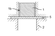
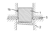
- Schematic diagram showing the process of punching a workpiece using a press processing device Schematic diagram showing the process of punching a workpiece using a press processing device
- Schematic diagram showing the process of punching a workpiece using a press processing device Schematic diagram showing the process of punching a workpiece using a press processing device
- Schematic diagram showing the process of punching a workpiece using a press processing device Schematic diagram showing the process of punching a workpiece using a press processing device
- Schematic diagram showing the process of punching a workpiece using a press processing device Schematic diagram showing the process of punching a workpiece using a press processing device
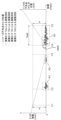
- FIG. 7 is a graph showing a vibration waveform when the wear of the punch in FIG. 6 is not progressing. 7 is a graph showing a vibration waveform when the wear of the punch in FIG. 6 progresses.
- FIG. 13 is a schematic diagram showing a press working device according to a second embodiment;
- FIG. 10 is a schematic diagram showing a state in which the punch of the press working device of FIG. 9 is at the bottom dead center;
- FIG. 10 is a top view showing a load sensor of the press working apparatus of FIG.
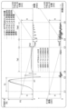
- a flowchart for explaining a process for calculating the amount of wear on the side surface of a punch in the press working device of FIG. 7 is a graph showing a load waveform generated based on the load detected by each of the four load sensors and a vibration waveform generated based on the vibration detected by the four vibration sensors shown in FIG. 14 is a graph in which the load waveform and vibration waveform when the punch is not worn out are superimposed on the load waveform and vibration waveform when the punch is worn out.
- Press working which performs punching on a plate-shaped workpiece, is a technique that generally involves pressing the workpiece loaded on a die with a stripper and forcing part of the workpiece into the die with a punch to punch out a desired shape. Press working by punching is generally used in a wide range of fields, such as home appliances, precision machinery, and automobile parts.
- the punching characteristic measuring device described in Patent Document 1 converts the frame deformation during punching into an electrical signal to measure the punching force during punching.
- the punching force is the resistance force when a laminate is punched with a die. As the die wears, the punching force increases, so it is being considered to use the punching force to calculate the die wear state and determine whether or not the tool needs to be re-ground.
- the punching characteristic measuring device described in Patent Document 1 has the problem that it cannot calculate the wear state of the die with high accuracy because it detects deformation of the frame at a position away from the machining position of the die.
- the punching characteristic measuring device described in Patent Document 1 still has room for improvement in terms of improving the accuracy of calculating the amount of tool wear.
- the inventor(s) have investigated a press processing device that can accurately calculate the amount of wear on a punch, and have come up with the following disclosure.
- This disclosure provides a press processing device that can improve the accuracy of calculating the amount of wear on a punch.
- FIG. 1 is a schematic diagram showing a press working apparatus 100 according to a first embodiment of the present disclosure.
- Fig. 2 is a schematic diagram showing a bottom dead center state of a punch 1 of the press working apparatus 100 of Fig. 1.
- Fig. 3 is a top view showing a vibration sensor 19 of the press working apparatus 100 of Fig. 1. Note that some components are omitted from Figs. 2 and 3.
- the press working apparatus 100 according to the present embodiment will be described with reference to Figs. 1 to 3.
- the X-Y-Z coordinate system shown in each figure is intended to facilitate understanding of the embodiment, and does not limit the embodiment.
- the X direction is the width direction of the press processing device 100
- the Y direction is the depth direction of the press processing device 100
- the Z direction is the height direction of the press processing device 100.
- the press processing device 100 is a device that performs punching on a plate-shaped workpiece 5, and is, for example, a servo screw press device that can be controlled with high precision.
- the press processing device 100 includes a press device main body 9 and a control unit 18.
- the press device main body 9 includes a punch 1, a die 2, a position sensor 13, and a vibration sensor 19.
- the press device main body 9 and the control unit 18 may be housed in a single housing.
- the control unit 18 may be a control circuit such as a CPU mounted on a device other than the press device main body 9, for example, an electronic device. Even when the control unit 18 is mounted on a device other than the press device main body 9, the press device main body 9 and the control unit 18 are collectively referred to as the "press processing device.”
- the press processing system when the control unit 18 is mounted on a device other than the press device main body 9, the press device main body 9 and the control unit 18 may be collectively referred to as the "press processing system.”
- the press processing device 100 includes a punch 1, a die 2, a position sensor 13, a vibration sensor 19, and a control unit 18.
- the press body 9 of the press processing device 100 has an upper die including a punch 1 attached to a slide 7, and a lower die including a die 2 attached to a bolster 8. Based on commands from the control unit 18, the press body 9 rotates a ball screw 12 connected to a servo motor 11 to drive the slide 7 up and down in the press direction (Z direction) along the shaft 10 at a predetermined speed. This operation of the press body 9 allows the workpiece 5 to be punched.
- the punch 1 is a tool for moving in the press direction (Z direction) to punch out the workpiece 5.
- the punch 1 has a press surface 1a facing the workpiece 5 and a side surface 1b connected to the press surface 1a.
- the punch 1 is attached to a slide 7 together with a stripper plate 3 that presses the workpiece 5 against the die 2 during punching. As the slide 7 moves, the punch 1 is pressed against the workpiece 5 to perform punching.
- the punch 1 has a circular press surface 1a. Therefore, the workpiece 5 can be punched out in a circular shape.
- the punch 1 is formed in a cylindrical shape with a circular press surface 1a having a diameter of 4.5 mm, and punches a circular hole in the workpiece 5.
- the punch 1 is made of, for example, a superhard material.
- a superhard material is an artificial metal (alloy) in which nine types of carbides of W (tungsten), Cr (chromium), Mo (molybdenum), Ti (titanium), Zr (zirconium), Hf (hafnium), V (vanadium), Nb (niobium), and Ta (tantalum) are bonded with an Fe group metal (Fe, Co, or Ni).
- an alloy equivalent to VM-40 of the Cemented Carbide Tool Association Standard (CIS) can be used as the superhard material.
- a workpiece 5 is placed on the die 2 during punching.
- a hollow portion 2a into which the punch 1 is inserted is formed in the die 2.
- the hollow portion 2a is a through hole that passes through the die 2 in the Z direction.
- the die 2 is attached to a bolster 8 together with a die plate 4 for holding the die 2.
- the die 2 is made of, for example, a superhard material, similar to the punch 1.
- a vibration sensor 19 for detecting vibration of the die 2 is disposed in the die 2.
- the position sensor 13 is a sensor that detects the position of the punch 1. More specifically, the position sensor 13 can detect that the punch 1 shown in FIG. 2 is in the lowest possible position, i.e., the bottom dead center state. Furthermore, the position sensor 13 can detect how much the punch 1 has risen from the bottom dead center state. In this embodiment, the degree to which the punch 1 has risen from the bottom dead center state is detected as the position of the punch 1.
- the position sensor 13 can be configured, for example, by a displacement sensor that measures a minute distance interval from the measurement object in a non-contact manner.
- the position sensor 13 can be attached to any position of the lower die of the press working device 100, which includes, for example, the die 2, the die plate 4, and the bolster 8.
- the position sensor 13 detects that the punch 1 is at the bottom dead center by detecting contact between the upper die, which includes the punch 1, the stripper plate 3, and the slide 7, and the position sensor 13, and detects the position of the punch 1 by measuring the distance between the upper die and the position sensor 13.
- the timing at which the vibration sensor 19 starts detecting the vibration of the die 2 can be determined based on the position of the punch 1 detected by the position sensor 13. Specifically, the detection start timing can be determined based on the gap of the position sensor 13 and the position of the punch 1 from the bottom dead center so that detection of the vibration of the die 2 can start at the same timing as the punching shot. Therefore, the position sensor 13 can be used as a trigger for the vibration sensor 19 to detect the vibration of the die 2. Furthermore, for example, if a position sensor 13 is placed at each of the four corners of the lower die, it can also detect whether the upper die and the lower die are arranged in parallel.
- the vibration sensor 19 is a sensor that detects the vibration of the die 2.
- the vibration sensor 19 detects the vibration transmitted from the work 5 to the die 2 when the work 5 is punched.
- the vibration sensor 19 includes four vibration sensors 19a to 19d.
- the four vibration sensors 19a to 19d are arranged at equal intervals around the hollow portion 2a of the die 2.
- the vibration sensor 19a and the vibration sensor 19b are arranged symmetrically in the X direction
- the vibration sensor 19c and the vibration sensor 19d are arranged symmetrically in the Y direction
- the four vibration sensors 19a to 19d are arranged on concentric circles.
- the control unit 18 controls the punch 1, the die 2, the position sensor 13, and the vibration sensor 19.
- the control unit 18 has a press controller 14, a sensor controller 15, a calculation unit 16, and a determination unit 17.
- the control unit 18 is configured with digital circuits such as a microcomputer, a CPU, an MPU, a GPU, a DSP, an FPGA, an ASIC, etc.
- the press controller 14 drives the servo motor 11 to rotate the ball screw 12, thereby driving the slide 7 up and down in the press direction (Z direction) at a predetermined speed.
- the sensor controller 15 is electrically connected to the position sensor 13 and the vibration sensor 19, and outputs the detection values of the respective sensors 13 and 19 to the calculation unit 16.
- the calculation unit 16 generates a vibration waveform indicating the relationship between the vibration of the die 2 and the time after the punch 1 reaches the bottom dead center based on the vibration detected by the vibration sensor 19, and calculates the first wear amount of the side surface 1b of the punch 1 based on the vibration waveform. When punching processing is repeated, the punch 1 gradually wears out. In this embodiment, the calculation unit 16 calculates the wear amount of the side surface 1b of the punch 1. The generation of the vibration waveform and the calculation of the wear amount will be described in detail later.
- the determination unit 17 determines whether or not the punch 1 needs to be ground based on the first wear amount of the side surface 1b calculated by the calculation unit 16. As the wear amount of the punch 1 increases, the accuracy of the punching dimensions of the workpiece 5 gradually deteriorates. For this reason, it is advisable to ground the punch 1 when the wear amount exceeds a predetermined threshold value.
- the determination unit 17 determines that the punch 1 needs to be ground, the determination unit 17 outputs a signal to the press controller 14 to interrupt the punching process. Having received the signal, the press controller 14 stops the servo motor 11 and interrupts the punching process. Note that the determination unit 17 is not a required component, and the control unit 18 does not have to determine whether or not the punch 1 needs to be ground.
- the workpiece 5 is a plate-shaped material to be processed by the press processing device 100.
- a plurality of workpieces 5 are transported in the X direction or the Y direction by a transport unit (not shown) in accordance with the pressing operation of the press device main body 9, and are sequentially punched.
- the workpiece 5 is made of SUS301-EH material, which is a type of steel classified as austenitic stainless steel.
- SUS301-EH material is a material used, for example, as mainsprings or springs in automobile parts.
- the workpiece 5 has a thickness of 0.03 mm, a hardness of 529 HV, and a tensile strength of 1,679 N/ mm2 .
- [Calculation of wear amount] 4 is a flow chart for explaining a process for calculating the amount of wear of the side surface 1b of the punch 1 in the press working device 100. The calculation of the amount of wear of the side surface 1b of the punch 1 will be explained with reference to FIG.
- step S1 the vibration sensor 19 detects the vibration of the die 2.
- the vibration sensor 19 starts detecting the vibration of the die 2.
- the vibration of the die 2 is detected by each of the four vibration sensors 19a to 19d.
- step S2 the calculation unit 16 generates a vibration waveform that indicates the relationship between the vibration of the die 2 and time.
- the vibration of the die 2 detected in step S1 is output to the calculation unit 16 by the sensor controller 15 of the control unit 18, and the calculation unit 16 generates a vibration waveform.
- FIGS. 5A to 5G are schematic diagrams showing the process of punching the workpiece 5 with the press processing device 100.
- FIG. 6 is a graph showing the relationship between the load (left vertical axis) detected by the four vibration sensors 19a to 19d and the position of the punch 1 from the bottom dead center (right vertical axis) and time during punching.
- FIG. 6 is a graph that overlays four vibration waveforms generated based on the vibration of the die 2 detected by each of the four vibration sensors 19a to 19d. Note that FIG. 6 shows the vibration waveform when the side surface 1b of the punch 1 is almost not worn.
- punch 1 descends in the Z direction from the top dead center state, and as shown in Figure 5A, punch 1 comes into contact with workpiece 5.
- the top dead center state refers to the state in which punch 1 is in the highest position it can be in.
- time C1 indicates the time when punch 1 begins to come into contact with workpiece 5.
- time C2 indicates the time when punch 1 completes the cutting of workpiece 5.
- punch 1 pushes the portion cut off from the workpiece 5 into the hollow portion of die 2, as shown in Figure 5D.
- the load on punch 1 changes from positive reaction force P1 to negative reaction force P2 in the opposite direction (+Z direction) to the positive reaction force P1 shown in Figure 2.
- punch 1 is subjected alternately to positive reaction force P1 and negative reaction force P2, causing it to vibrate.
- the vibration of punch 1 is transmitted to die 2 via workpiece 5.
- Region R1 in Figure 6 shows the vibration of die 2 detected after cutting of the workpiece 5 is complete.
- punch 1 reaches bottom dead center.
- the time when punch 1 reaches bottom dead center is time C3.
- vibration may be detected before punch 1 reaches bottom dead center. This vibration occurs when vibration is transmitted from workpiece 5 to die 2 when workpiece 5, which has been cut off, falls away from the tip of punch 1.
- the vibration waveforms of the vibration sensors 19a to 19d will be substantially the same, as shown in Figure 6. Note that the vibration waveforms of the vibration sensors 19a to 19d may differ slightly due to subtle differences in the clearance between the punch 1 and the die 2.
- FIG. 6 shows a vibration waveform from when punch 1 starts to descend from top dead center, when it reaches bottom dead center, and then when it returns to top dead center again.
- it is sufficient to generate a vibration waveform at least after punch 1 reaches bottom dead center.
- the calculation unit 16 when the calculation unit 16 generates a vibration waveform in step S2, the calculation unit 16 calculates the amount of wear on the side surface 1b of the punch 1 in step S3. The amount of wear on the side surface 1b of the punch 1 is calculated based on the respective vibration waveforms shown in FIG. 6.
- the first wear amount of the side surface 1b of the punch 1 is calculated using a vibration waveform that shows the change in vibration during a predetermined period from time C4 to time C5, i.e., from when the punch 1 starts to rise from the bottom dead center.
- the predetermined period from when the punch 1 starts to rise from the bottom dead center can be the period from when the punch 1 starts to rise from the bottom dead center at time C4 to when the punch 1 completely comes out of the hollow portion 2a of the die 2 at time C5.
- the predetermined period can be the time from time C4 to when the punch 1 reaches top dead center.
- FIG. 7A is a graph showing the vibration waveform when the wear of punch 1 in FIG. 6 has not progressed.
- FIG. 7B is a graph showing the vibration waveform when the wear of punch 1 in FIG. 6 has progressed.
- the maximum value of the vibration of the die 2 during the period Tsb0 is maximum value Asb0.
- the maximum value of the vibration of the die 2 during the period Tsb0 becomes maximum value Asb1.
- the vibration sensor 19 detects vibrations greater than 0 and vibrations less than 0 depending on the direction of vibration, so the maximum vibration value Asb may be the maximum absolute value of the vibration during the period Tsb0.
- calculation unit 16 can calculate the first wear amount d of side 1b of punch 1 based on the maximum vibration value of die 2 during period Tsb0.
- the calculation unit 16 calculates the first wear amount d of the side surface 1b of the punch 1 based on the maximum vibration value Asb of the die 2 during the period Tsb0 in the vibration waveform.
- the press processing device 100 has four vibration sensors 19a to 19d, and four vibration waveforms shown in FIG. 6 are generated. Therefore, the first wear amount d is calculated for each of the four vibration waveforms.
- the calculation unit 16 can calculate the wear position of the punch 1 by calculating the first wear amount d for each of the four vibration waveforms.
- the first wear amount d for the vibration waveform generated by the detection value of the vibration sensor 19a indicates the wear amount of the part of the side surface 1b of the punch 1 that faces the vibration sensor 19a when the punch 1 reaches the bottom dead center.
- the four vibration sensors 19a to 19d are arranged, it is possible to identify to some extent the parts of the side surface 1b of the punch 1 that are worn or not worn.
- the load on the side of the punch 1 increases.
- the maximum value Asb of the vibration of the die 2 during the period Tsb0 increases significantly. Therefore, by using the maximum value Asb of the vibration of the die 2 during the period Tsb0, the first wear amount d of the side 1b of the punch 1 can be calculated with high accuracy.
- step S4 after calculating the first wear amount d of the side surface 1b of the punch 1, in step S4, the judgment unit 17 judges whether or not grinding of the punch 1 is necessary.
- the determination unit 17 determines that the punch 1 needs to be ground when the first wear amount d of the side surface 1b of the punch 1 exceeds the first threshold value. In this embodiment, when at least one of the first wear amounts d calculated from each of the four vibration waveforms is greater than the first threshold value, the determination unit 17 determines that the punch 1 needs to be ground.
- step S4 If the determination unit 17 determines in step S4 that grinding of the punch 1 is necessary, the press controller 14 stops the operation of the press processing device 100, the punching process is interrupted, and the process ends.
- step S4 If the determination unit 17 determines in step S4 that grinding of the punch 1 is not necessary, the punching process continues and the process returns to step S1.
- control unit 18 includes the determination unit 17, and the determination unit 17 determines whether or not grinding of the punch 1 is necessary based on the first wear amount d calculated by the calculation unit 16, but this is not limiting.
- the control unit 18 does not need to include the determination unit 17, and it is sufficient that in the press processing device 100, the calculation unit 16 can calculate the first wear amount d of the side surface 1b of the punch 1 based on the vibration waveform from the vibration sensor 19.
- the material of the workpiece 5 is SUS301-EH material, but this is not limited to this.
- the workpiece 5 can be made of various metal materials.
- the thickness of the workpiece 5 is not limited to 0.03 mm, and can be any thickness.
- the punch 1 has a circular press surface 1a, but this is not limited to this.
- the shape of the press surface 1a is not limited to a circle, and can be any shape, such as a polygon or ellipse.
- the press processing device 100A is equipped with a load sensor 6.
- the load sensor 6 is a sensor that detects the load applied to the punch 1.
- the load sensor 6 detects the load applied in the press direction (Z direction) of the punch 1 when the punch 1 punches the workpiece 5.
- the load applied in the press direction of the punch 1 includes a positive reaction force P1 in the -Z direction and a negative reaction force P2 in the +Z direction.
- the positive reaction force P1 is the load that is applied to the punch 1 mainly when the punch 1 punches the workpiece 5 ( Figures 5A to 5C).
- the negative reaction force P2 is the load that is applied to the punch 1 mainly when the punch 1 rises from the bottom dead center ( Figures 5D to 5F).
- the load sensor 6 in order for the load sensor 6 to detect the load acting on the punch 1, the punch 1, the load sensor 6, and the free shank 20 above the load sensor 6 are fixed with a fastening bolt or the like (not shown). Therefore, the load sensor 6 can detect both the positive reaction force P1 in the -Z direction when the workpiece 5 is punched, and the negative reaction force P2 in the +Z direction when the punch 1 rises from the bottom dead center.
- the load sensor 6 includes four load sensors 6a to 6d.
- the load sensors 6a and 6b are arranged symmetrically in the Y direction, and the load sensors 6c and 6d are arranged symmetrically in the X direction.
- the four load sensors 6a to 6d are arranged at equal intervals on concentric circles. By arranging the four sensors 6a to 6d in this manner, it becomes easier to determine which parts of the punch 1 are worn.
- the sensor controller 15 of the control unit 18 is electrically connected to the load sensor 6, the position sensor 13, and the vibration sensor 19, and outputs the detection values of the respective sensors 6, 13, and 19 to the calculation unit 16 of the control unit 18.
- the calculation unit 16 generates a load waveform indicating the relationship between the load detected by the load sensor 6 and the time from the start of processing, based on the load of the punch 1 detected by the load sensor 6, in addition to the vibration waveform described in the first embodiment.
- the calculation unit 16 calculates a first wear amount d of the side surface of the punch 1 based on the vibration waveform.
- the calculation unit 16 also calculates a second wear amount b of the side surface 1b of the punch 1 based on the load waveform from the time when processing of the workpiece 5 is completed to the time when the punch 1 reaches the bottom dead center, out of the generated load waveforms.
- the calculation unit 16 calculates a third wear amount c of the side surface 1b of the punch 1 based on the load waveform from the time when the punch 1 starts to rise from the bottom dead center, out of the generated load waveforms.
- the determination unit 17 determines whether or not grinding of the punch 1 is necessary based on at least one of the first wear amount d, the second wear amount b, and the third wear amount c of the side surface 1b calculated by the calculation unit 16.
- the determination unit 17 may determine that grinding of the punch 1 is necessary, for example, when at least one of the second wear amount b and the third wear amount c exceeds a second threshold value.
- the determination unit 17 may determine that grinding of the punch 1 is necessary, when the largest value among the first wear amount d, the second wear amount b, and the third wear amount c exceeds a predetermined threshold value.
- FIG. 12 is a flow chart for explaining a process for calculating the amount of wear of the side surface 1b of the punch 1 in the press working apparatus 100A of Fig. 9. The calculation of the amount of wear of the side surface 1b of the punch 1 in this embodiment will be explained with reference to Fig. 12. Note that steps S11, S13, and S15 in Fig. 12 are similar to steps S1, S2, and S3 in Fig. 4, respectively, and therefore will not be explained.
- step S12 the load sensor 6 detects the load applied to the punch 1.
- each of the four load sensors 6a to 6d detects the load.
- the load detected by the load sensor 6 is output to the calculation unit 16 via the sensor controller 15 of the control unit 18.
- step S14 the calculation unit 16 generates a load waveform that indicates the relationship between the load applied to the punch 1 and time.
- FIG. 13 is a graph showing load waveforms generated based on the loads detected by each of the four load sensors 6a to 6d, and vibration waveforms generated based on the vibrations detected by the four vibration sensors 19a to 19d shown in FIG. 6.
- the load waveforms and vibration waveforms are aligned along the horizontal axis. Note that FIG. 13 shows the load waveforms and vibration waveforms when the side surface 1b of the punch 1 is almost unwearable.
- punch 1 when punching starts, punch 1 starts machining in the +Z direction from the top dead center, and punch 1 comes into contact with workpiece 5.
- punch 1 is at height H from bottom dead center at time C1.
- punch 1 is in contact with the top surface of workpiece 5, as shown in FIG. 5A.
- a positive reaction force P1 begins to act on punch 1. Therefore, time C1 on the graph of FIG. 13 is the point at which punch 1 comes into contact with workpiece 5 and the positive reaction force P1 acting on punch 1 becomes greater than 0.
- positive reaction force P1 is shown as a value greater than 0, and negative reaction force P2, which will be described later, is shown as a value less than 0.
- punch 1 comes into contact with workpiece 5
- punch 1 starts punching workpiece 5, as shown in FIG. 5B.
- a load starts to be applied to punch 1 from time C1, and the load on punch 1 increases rapidly.
- the load on punch 1 reaches a maximum value P0 at time m1.
- Time C2 represents the point in time when the load on punch 1 drops to 0 after reaching its maximum value P0.
- the load on punch 1 drops to 0 after reaching its maximum value P0 because punch 1 punches through the workpiece 5 and there is no longer any resistance to punch 1.
- the load sensors 6a to 6d are fixed to the punch 1 by the free shank 20.
- a gap is formed between the flange receiving portion of the free shank 20 and the flange receiving portion of the free shank holder 22.
- the load applied to the load sensors 6a to 6d specifically, the positive reaction force P1 applied to the punch 1 becomes zero. Due to the gap between the flange receiving portion of the free shank 20 and the flange receiving portion of the free shank holder 22, the flange receiving portion of the free shank 20 comes into contact with and separates from the flange receiving portion of the free shank holder 22 in reaction to the punch 1 punching out the workpiece 5.
- the vibration waveform in Figure 13 shows that vibration of die 2 occurs between time C2 and time C6.
- the vibration that occurs between time C2 and time C6 is caused by the positive reaction force P1 and negative reaction force P2 being applied to punch 1, which causes punch 1 to vibrate, and the vibration of punch 1 is transmitted to die 2 via workpiece 5.
- the workpiece 5 cut by the punch 1 is pushed into the hollow portion 2a of the die 2 as shown in Figure 5D.
- a positive reaction force P1 may be applied to the punch 1. This is because the side surface 1b of the punch 1 and the workpiece 5 interfere with each other as shown in Figures 5D and 5E.
- the positive reaction force P1 caused by the interference between the side surface 1b of the punch 1 and the workpiece 5 occurs between time C6 and time C3 in Figure 13, and the load on the punch 1 becomes zero at time C3.
- the load waveforms generated based on the loads detected by the load sensors 6a to 6d each have approximately the same shape.
- the load waveforms of the load sensors 6a to 6d may differ slightly.
- a load is applied to punch 1 due to interference between side surface 1b of punch 1 and workpiece 5 between time C6 and time C3, and between time C4 and time C5.
- the calculation unit 16 calculates the second wear amount b and the third wear amount c of side surface 1b of punch 1 based on the load waveform during this period.
- step S16 the calculation unit 16 calculates the second wear amount b of the side surface 1b of the punch 1 based on the load waveform from when the processing of the workpiece 5 is completed until the punch reaches the bottom dead center, i.e., from time C6 to time C3.
- the calculation unit 16 calculates the second wear amount b of the side surface 1b of the punch 1 based on the maximum load value Ps0 during the period Ts0 from time C6 to time C3.
- FIG. 14 is a graph in which the load waveform and vibration waveform when the punch 1 is worn out are superimposed on the load waveform and vibration waveform when the punch 1 is not worn out in FIG. 13.
- the load waveform (dashed line) from the load sensor 6a and the vibration waveform (dashed line) based on the vibration sensor 19a when the punch 1 is not worn out are superimposed on the vibration waveform based on the load sensor 6a (solid line) and the vibration sensor 19a (solid line) when the punch 1 is worn out.
- the maximum value of the load applied to punch 1 during time period Ts0 is maximum value Ps0.
- the maximum value of the load applied to punch 1 during time period Ts0 becomes maximum value Ps1.
- calculation unit 16 can calculate the second wear amount b of side 1b of punch 1 based on the maximum value of the load applied to punch 1 during time period Ts0.
- the workpiece 5 is a 0.03 mm thick stainless steel plate made of SUS301-EH material, and punching is performed under conditions of an instantaneous speed of the punch 1 during punching of 3 mm/s and no press oil.
- the relationship of the following formula (2) is established between the maximum value Ps of the load applied to the punch 1 during the period Ts0 and the second wear amount b of the side surface 1b of the punch 1.
- the first wear amount d was calculated based on the maximum vibration value of the die 2 during the period Tsb0, but in this embodiment, the calculation unit 16 calculates the third wear amount c of the side surface 1b of the punch 1 based on the maximum load applied to the punch 1 during the period Tsb0.
- the load applied to punch 1 is negative reaction force P2. Therefore, as shown in the load waveform in Figure 13, the load applied to punch 1 in period Tsb0 is a value smaller than 0. In period Tsb0, the maximum value of the load applied to punch 1 is maximum value Psb0. Note that the maximum value of the load on punch 1 in period Tsb0 is the maximum absolute value of the load on punch 1. As wear of punch 1, particularly wear of the side surface 1b of punch 1, progresses, the maximum value of the load applied to punch 1 in period Tsb0 becomes maximum value Psb1.
- calculation unit 16 can calculate the third wear amount c of side 1b of punch 1 based on the maximum value of the load applied to punch 1 during period Tsb0.
- the workpiece 5 is a 0.03 mm thick stainless steel plate made of SUS301-EH material
- the instantaneous speed of the punch 1 during punching is 3 mm/s
- punching is performed without press oil.
- the relationship of the following formula (3) is established between the maximum value Psb of the load applied to the punch 1 during the period Tsb0 and the third wear amount c of the side surface 1b of the punch 1.
- step S15 to S17 the calculation unit 16 calculates the amount of wear on the side surface 1b, and in step S18, the judgment unit 17 judges whether or not the punch 1 needs to be polished.
- the wear amounts of side surface 1b are calculated as follows: first wear amount d is 1.20 ⁇ m, second wear amount b is 1.27 ⁇ m, and third wear amount c is 1.25 ⁇ m.
- the determination unit 17 can determine that punch 1 needs to be polished based on, for example, the fact that the largest wear amount among the first wear amount d, second wear amount b, and third wear amount c exceeds a predetermined threshold value. By using the largest value among the first wear amount d, second wear amount b, and third wear amount c, it is possible to determine whether punch 1 needs to be polished while taking into account calculation errors in the wear amounts.
- the judgment unit 17 may judge whether or not the punch 1 needs to be ground based on the magnitude of the allowable amount of wear. For example, assume that the allowable burr size of a product manufactured by the press processing device 100A is 5 ⁇ m. As a result of calculating the amount of wear when a burr of 5 ⁇ m occurs on the product, the first wear amount d of the side surface 1b of the punch 1 is 1.20 ⁇ m, the second wear amount b is 1.27 ⁇ m, and the third wear amount c is 1.25 ⁇ m. Therefore, the allowable amounts of wear on the side surface 1b are the first wear amount d of 1.20 ⁇ m, the second wear amount b of 1.27 ⁇ m, and the third wear amount c of 1.25 ⁇ m.
- the judgment unit 17 may use the smallest allowable amount of wear among the first wear amount d, the second wear amount b, and the third wear amount c to determine whether or not the punch 1 needs to be ground. In this case, the judgment unit 17 uses the first wear amount d, which is the smallest allowable amount of wear, to judge whether or not the punch 1 needs to be ground. The determination unit 17 can determine that the punch 1 needs to be polished, for example, based on the first wear amount d exceeding a predetermined threshold value.
- the determination unit 17 may determine that grinding of the punch is necessary when at least one of the second wear amount b and the third wear amount c exceeds a second threshold value.
- Which of the first wear amount d, the second wear amount b, or the third wear amount c is used to determine whether or not the punch 1 needs to be polished may be determined in advance based on processing conditions such as the material or thickness of the workpiece 5, the material of the punch 1 and the die 2, the punching speed, and the presence or absence of press oil.
- step S18 If the determination unit 17 determines in step S18 that grinding of the punch 1 is necessary, the press controller 14 stops driving the press processing device 100A, the punching process is interrupted, and the process ends.
- step S4 If the determination unit 17 determines in step S4 that grinding of the punch 1 is not necessary, the punching process continues and the process returns to step S11.
- the press working device 100A capable of calculating the amount of wear of the side surface 1b of the punch 1 with higher accuracy.
- the amount of wear of the side surface 1b of the punch 1 is calculated using a load waveform generated based on the load applied to the punch 1 in addition to the vibration waveform. It is possible to determine whether or not the punch 1 needs to be polished based on the first amount of wear d of the side surface 1b of the punch 1 based on the vibration waveform, or the second amount of wear b and the third amount of wear c of the side surface 1b of the punch 1 based on the load waveform, whichever is calculated with higher accuracy.
- the load sensor 6 includes four load sensors 6a to 6d has been described, but this is not limiting.
- the load sensor 6 can include one or two or more load sensors.
- the calculation unit 16 calculates the second wear amount b and the third wear amount c based on the load waveform, but this is not limiting.
- the calculation unit 16 may calculate the second wear amount b based on the load waveform, and the determination unit 17 may determine whether or not the punch 1 needs to be polished based on the first wear amount d and the second wear amount b.
- the press processing apparatus of the present disclosure is a press processing apparatus that performs press processing on a workpiece, and includes a punch having a press surface and a side connected to the press surface, a die on which the workpiece is placed and which has a hollow portion into which the punch is inserted, a position sensor that detects the position of the punch, a vibration sensor that detects vibration of the die, and a control unit that controls the punch, the die, the position sensor, and the vibration sensor, wherein the control unit generates a vibration waveform that indicates the relationship between the vibration detected by the vibration sensor and the time after the punch reaches bottom dead center, and calculates a first wear amount of the side of the punch based on the vibration waveform.
- the vibration waveform may show a change in vibration over a predetermined period of time from when the punch starts to rise from the bottom dead center using a position sensor.
- control unit may determine that grinding of the punch is necessary when the first wear amount exceeds a first threshold value.
- a load sensor is further provided to detect the load applied to the punch, and the control unit generates a load waveform indicating the relationship between the load detected by the load sensor and the time from the start of press processing, and may calculate the second wear amount of the side of the punch based on the load waveform during the period from when processing of the workpiece is completed to when the punch reaches the bottom dead center.
- the need to grind the punch may be determined based on the first wear amount or the second wear amount.
- control unit may calculate a third wear amount on the side of the punch based on the load waveform during a predetermined period from when the punch starts to rise from the bottom dead center, and determine whether or not the punch needs to be polished based on at least one of the first wear amount, the second wear amount, and the third wear amount.
- control unit may determine that grinding of the punch is necessary when at least one of the second wear amount and the third wear amount exceeds a predetermined second threshold value.
- the vibration sensor may include multiple vibration sensors.
- the multiple vibration sensors may be arranged at equal intervals around the hollow portion of the die.
- control unit may calculate the wear position of the punch based on a plurality of load waveforms indicating the relationship between the vibration detected by each of the plurality of vibration sensors and time.
- the load sensor may include multiple load sensors.
- the present invention provides a press processing device that can improve the accuracy of calculating the amount of wear on a punch.
- the press processing device disclosed herein is useful as a device for punching any workpiece used in home appliances, medical equipment, etc.
- REFERENCE SIGNS LIST 1 punch 1a press surface 1b side surface 2 die 2a hollow portion 3 stripper plate 4 die plate 5 workpiece 6, 6a to 6d load sensor 7 slide 8 bolster 9 press device body 10 shaft 11 servo motor 13 position sensor 14 press controller 15 sensor controller 16 calculation unit 17 determination unit 18 control unit 19, 19a to 19d vibration sensor 20 free shank 21 backing plate 22 free shank holder 100, 100A press processing device
Landscapes
- Physics & Mathematics (AREA)
- General Physics & Mathematics (AREA)
- Engineering & Computer Science (AREA)
- Mechanical Engineering (AREA)
- Punching Or Piercing (AREA)
Priority Applications (2)
| Application Number | Priority Date | Filing Date | Title |
|---|---|---|---|
| JP2025521886A JPWO2024241789A1 (https=) | 2023-05-23 | 2024-04-19 | |
| CN202480031829.XA CN121100030A (zh) | 2023-05-23 | 2024-04-19 | 冲压加工装置 |
Applications Claiming Priority (2)
| Application Number | Priority Date | Filing Date | Title |
|---|---|---|---|
| JP2023084504 | 2023-05-23 | ||
| JP2023-084504 | 2023-05-23 |
Related Child Applications (1)
| Application Number | Title | Priority Date | Filing Date |
|---|---|---|---|
| US19/382,717 Continuation US20260124663A1 (en) | 2023-05-23 | 2025-11-07 | Press working apparatus |
Publications (1)
| Publication Number | Publication Date |
|---|---|
| WO2024241789A1 true WO2024241789A1 (ja) | 2024-11-28 |
Family
ID=93589988
Family Applications (1)
| Application Number | Title | Priority Date | Filing Date |
|---|---|---|---|
| PCT/JP2024/015590 Ceased WO2024241789A1 (ja) | 2023-05-23 | 2024-04-19 | プレス加工装置 |
Country Status (3)
| Country | Link |
|---|---|
| JP (1) | JPWO2024241789A1 (https=) |
| CN (1) | CN121100030A (https=) |
| WO (1) | WO2024241789A1 (https=) |
Citations (6)
| Publication number | Priority date | Publication date | Assignee | Title |
|---|---|---|---|---|
| JPH09251007A (ja) * | 1996-03-14 | 1997-09-22 | Hihakai Kensa Kk | プレス加工用金型の劣化度評価方法及び評価装置 |
| JP2004358487A (ja) * | 2003-06-02 | 2004-12-24 | Denso Corp | 塑性加工品の異常判別評価方法及びその異常判別評価装置 |
| KR20070105593A (ko) * | 2006-04-27 | 2007-10-31 | 김용연 | 음향신호처리에 의한 천공금형의 마모 상태 감시 방법 |
| JP2017209698A (ja) * | 2016-05-24 | 2017-11-30 | 日本デイトンプログレス株式会社 | プレス装置及びそれに使用されるバッキングプレート |
| WO2022180984A1 (ja) * | 2021-02-26 | 2022-09-01 | パナソニックIpマネジメント株式会社 | 推定モデル生成装置および工具寿命推定装置 |
| WO2022181059A1 (ja) * | 2021-02-26 | 2022-09-01 | パナソニックIpマネジメント株式会社 | 推定モデル生成装置および工具寿命推定装置 |
-
2024
- 2024-04-19 WO PCT/JP2024/015590 patent/WO2024241789A1/ja not_active Ceased
- 2024-04-19 CN CN202480031829.XA patent/CN121100030A/zh active Pending
- 2024-04-19 JP JP2025521886A patent/JPWO2024241789A1/ja active Pending
Patent Citations (6)
| Publication number | Priority date | Publication date | Assignee | Title |
|---|---|---|---|---|
| JPH09251007A (ja) * | 1996-03-14 | 1997-09-22 | Hihakai Kensa Kk | プレス加工用金型の劣化度評価方法及び評価装置 |
| JP2004358487A (ja) * | 2003-06-02 | 2004-12-24 | Denso Corp | 塑性加工品の異常判別評価方法及びその異常判別評価装置 |
| KR20070105593A (ko) * | 2006-04-27 | 2007-10-31 | 김용연 | 음향신호처리에 의한 천공금형의 마모 상태 감시 방법 |
| JP2017209698A (ja) * | 2016-05-24 | 2017-11-30 | 日本デイトンプログレス株式会社 | プレス装置及びそれに使用されるバッキングプレート |
| WO2022180984A1 (ja) * | 2021-02-26 | 2022-09-01 | パナソニックIpマネジメント株式会社 | 推定モデル生成装置および工具寿命推定装置 |
| WO2022181059A1 (ja) * | 2021-02-26 | 2022-09-01 | パナソニックIpマネジメント株式会社 | 推定モデル生成装置および工具寿命推定装置 |
Also Published As
| Publication number | Publication date |
|---|---|
| JPWO2024241789A1 (https=) | 2024-11-28 |
| CN121100030A (zh) | 2025-12-09 |
Similar Documents
| Publication | Publication Date | Title |
|---|---|---|
| JP6803161B2 (ja) | 金型の異常予測システム、それを備えたプレス機及び金型の異常予測方法 | |
| Chang et al. | Burr size reduction in drilling by ultrasonic assistance | |
| Nik et al. | Ultrasonic-assisted grinding of Ti6Al4 V alloy | |
| EP2590762B1 (en) | Joining method | |
| WO2023171001A1 (ja) | プレス加工装置 | |
| Sari et al. | Preliminary study for online monitoring during the punching process | |
| Fiorentino | Force-based failure criterion in incremental sheet forming | |
| CN111819022B (zh) | 搅拌摩擦焊接中避免焊接过程中断,特别是摩擦销断裂的装置及方法 | |
| JP2017209698A (ja) | プレス装置及びそれに使用されるバッキングプレート | |
| JP2012091277A (ja) | 切削品質維持方法 | |
| JP2020138210A (ja) | 打ち抜き装置およびせん断加工装置 | |
| CN110023000A (zh) | 折弯机的操作方法 | |
| WO2024241789A1 (ja) | プレス加工装置 | |
| JP7808773B2 (ja) | プレス加工装置 | |
| US20260124663A1 (en) | Press working apparatus | |
| EP4470691A1 (en) | Method for performing shearing work on amorphous alloy foil | |
| EP2233282A2 (en) | Press machine | |
| EP3587022B1 (en) | Linear friction-joining device and linear friction-joining method | |
| Cardoso et al. | Micro milling of metallic materials-a brief overview | |
| Kudla | Deformations and strength of miniature drills | |
| Hassan et al. | Tool pre-failure monitoring in intermittent cutting operations | |
| Voigts et al. | Investigation of Failure Mechanisms of Cemented Carbide Fine Blanking Punches by Means of Process Forces and Acoustic Emission | |
| CN110000514B (zh) | 一种超声振动滚压加工装置 | |
| US20260124662A1 (en) | Press-molding device | |
| WO2024241693A1 (ja) | プレス成形装置 |
Legal Events
| Date | Code | Title | Description |
|---|---|---|---|
| 121 | Ep: the epo has been informed by wipo that ep was designated in this application |
Ref document number: 24810797 Country of ref document: EP Kind code of ref document: A1 |
|
| ENP | Entry into the national phase |
Ref document number: 2025521886 Country of ref document: JP Kind code of ref document: A |
|
| NENP | Non-entry into the national phase |
Ref country code: DE |