WO2024241707A1 - 情報処理装置および方法、並びにプログラム - Google Patents
情報処理装置および方法、並びにプログラム Download PDFInfo
- Publication number
- WO2024241707A1 WO2024241707A1 PCT/JP2024/013177 JP2024013177W WO2024241707A1 WO 2024241707 A1 WO2024241707 A1 WO 2024241707A1 JP 2024013177 W JP2024013177 W JP 2024013177W WO 2024241707 A1 WO2024241707 A1 WO 2024241707A1
- Authority
- WO
- WIPO (PCT)
- Prior art keywords
- loudness
- information
- listener
- cvp
- value
- Prior art date
- Legal status (The legal status is an assumption and is not a legal conclusion. Google has not performed a legal analysis and makes no representation as to the accuracy of the status listed.)
- Ceased
Links
Images













Classifications
-
- H—ELECTRICITY
- H04—ELECTRIC COMMUNICATION TECHNIQUE
- H04R—LOUDSPEAKERS, MICROPHONES, GRAMOPHONE PICK-UPS OR LIKE ACOUSTIC ELECTROMECHANICAL TRANSDUCERS; ELECTRIC HEARING AIDS; PUBLIC ADDRESS SYSTEMS
- H04R3/00—Circuits for transducers
-
- H—ELECTRICITY
- H04—ELECTRIC COMMUNICATION TECHNIQUE
- H04S—STEREOPHONIC SYSTEMS
- H04S7/00—Indicating arrangements; Control arrangements, e.g. balance control
Definitions
- This technology relates to an information processing device, method, and program, and in particular to an information processing device, method, and program that can suppress the occurrence of clipping distortion.
- the level of the output signal from each speaker generated by the rendering process may exceed the range that can be recorded as digital audio data, resulting in clipping distortion.
- the playback sound may clip and become distorted. This will result in a decrease in the quality of the playback sound.
- This technology was developed in light of these circumstances, and makes it possible to suppress the occurrence of clipping distortion.
- the information processing device includes an acquisition unit that acquires loudness information defined for each of a plurality of positions or orientations that a listener can take in a space in which an object is placed, and a level correction unit that performs level correction on the audio data of the object based on the loudness information for each of the plurality of positions or orientations.
- the information processing method includes a step of acquiring loudness information defined for each of a plurality of positions or orientations that a listener can take in a space in which an object is placed, and performing level correction of the audio data of the object based on the loudness information for each of the plurality of positions or orientations.
- loudness information is obtained that is determined for each of a plurality of positions or orientations that a listener can take in a space in which an object is placed, and level correction is performed on the audio data of the object based on the loudness information for each of the plurality of positions or orientations.
- the information processing device includes a generating unit that generates a bitstream including loudness information defined for each of a plurality of positions or orientations that a listener can take in a space in which an object is placed, and a communication unit that transmits the bitstream.
- a bitstream is generated that includes loudness information defined for each of a number of possible positions or orientations of a listener in a space in which an object is placed, and the bitstream is transmitted.
- the information processing device of the third aspect of the present technology includes a correction unit that corrects the gain information of the object, determined for the control viewpoint, based on a measured loudness value, which is a measurement result of the loudness of audio data of content including the sound of one or more objects when the control viewpoint in space is set to the position of the listener, and a predetermined target loudness value.
- the information processing method includes a step of correcting the gain information of the object, which is determined for the control viewpoint, based on a measured loudness value, which is a measurement result of the loudness of audio data of content including the sound of one or more objects when the control viewpoint in space is set as the position of the listener, and a predetermined target loudness value.
- the gain information of the object defined for the control viewpoint is corrected based on a measured loudness value, which is the result of measuring the loudness of audio data of content including the sounds of one or more objects when the control viewpoint in space is set to the position of the listener, and a predetermined target loudness value.
- the information processing device of the fourth aspect of the present technology includes a control unit that generates configuration information including a measured loudness value that is a measurement result of the loudness of audio data of content that includes the sound of one or more objects when a control viewpoint in a space is set to the position of a listener.
- the information processing method includes a step of generating configuration information including a measured loudness value that is a measurement result of the loudness of audio data of content that includes the sound of one or more objects when a control viewpoint in a space is set to the position of a listener.
- configuration information is generated that includes a measured loudness value that is a measurement result of the loudness of audio data of content that includes the sounds of one or more objects when a control viewpoint in a space is set to the position of a listener.
- the information processing device includes a generating unit that generates a bitstream including configuration information that stores measured loudness values that are the measurement results of loudness of audio data of content that includes the sounds of one or more objects when a control viewpoint in a space is set to the position of a listener, and a communication unit that transmits the bitstream.
- a bitstream is generated that includes configuration information that stores measured loudness values that are the measurement results of the loudness of audio data of content that includes the sounds of one or more objects when the control viewpoint in the space is set to the position of the listener, and the bitstream is transmitted.
- FIG. 11A and 11B are diagrams illustrating clip distortion of a reproduced sound.
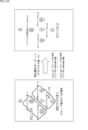
- FIG. 13 is a diagram illustrating region division in the horizontal direction.
- FIG. 13 is a diagram illustrating region division in the vertical direction.
- FIG. 13 is a diagram illustrating division points.
- FIG. 11 is a diagram showing an example of multi-angle loudness information.
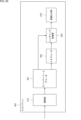
- FIG. 2 illustrates an example of a server configuration.
- FIG. 2 illustrates an example of the configuration of a client.
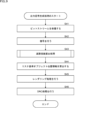
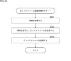
- 11 is a flowchart illustrating a bitstream transmission process.
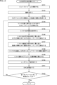
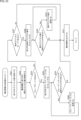
- 11 is a flowchart illustrating an output signal generation process.
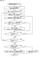
- 11 is a flowchart illustrating a damping coefficient calculation process.
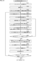
- 11 is a flowchart illustrating an output signal generation process.
- FIG. 13 is a diagram for explaining the selection of a CVP.
- FIG. 11 is a flowchart illustrating an output signal generation process.
- FIG. 11 is a diagram illustrating an interpolation process.
- 11 is a flowchart illustrating an output signal generation process.
- FIG. 2 is a diagram illustrating a loudness mode.
- FIG. 13 is a diagram illustrating a measurement loudness mode.
- FIG. 13 is a diagram illustrating a group mode.
- FIG. 13 is a diagram illustrating a group mode.
- FIG. 13 is a diagram illustrating a group mode.
- FIG. 2 is a diagram illustrating a production loudness mode.
- FIG. 2 is a diagram illustrating a production loudness mode.
- FIG. 1 is a diagram illustrating the flow of processing on the production side and the playback side.
- FIG. 1 is a diagram illustrating the flow of processing on the production side and the playback side.
- FIG. 13 is a diagram illustrating an example of the syntax of multi-loudness information.
- FIG. 11 is a diagram illustrating switching of configuration information.
- FIG. 11 is a diagram illustrating switching of configuration information.
- FIG. 13 is a diagram showing an example of a display screen.
- FIG. 13 is a diagram showing an example of a display screen.
- FIG. 13 is a diagram showing an example of a display screen.
- FIG. 13 is a diagram showing an example of a display screen.
- FIG. 2 illustrates an example of a server configuration.
- 11 is a flowchart illustrating a bitstream transmission process.
- FIG. 2 illustrates an example of the configuration of a client.
- FIG. 2 illustrates an example of a functional configuration of a client.
- 11 is a flowchart illustrating an output audio data generation process.
- 13 is
- This technology makes it possible to suppress the occurrence of clipping distortion by determining loudness information for each of a plurality of directions for each position in space.
- this technology can reduce the occurrence of clipping distortion even in situations where there are a small number of real speakers and a large number of objects are concentrated in an area with a small number of speakers.
- the listener can move its own position and change the direction it is facing (listener orientation).
- the level of the output signal for each speaker generated by the rendering process will exceed the range that can be recorded as digital audio data, such as PCM (Pulse Code Modulation) data, resulting in the playback sound clipping and becoming distorted.
- PCM Pulse Code Modulation
- loudness information is defined for multiple positions or directions, making it possible to reduce (suppress) clipping distortion in the playback sound for any viewpoint and listening direction.
- control viewpoints For example, in this technology, in a virtual space in which one or more objects constituting the content are placed, multiple viewpoint positions are designated (set) in advance by the content creator as control viewpoints (hereinafter also referred to as CVPs).
- CVPs control viewpoints
- the virtual space in which the objects are placed may be a two-dimensional space or a three-dimensional space, but the following description will be given assuming that the virtual space is a three-dimensional space.
- the content creator specifies (sets) in advance as the CVP (control viewpoint), the position in the virtual space from which they want the listener to listen when the content is played back, that is, the viewpoint from which they want the sound of the content to be heard.
- the content may be, for example, audio content consisting of sound only, or video content consisting of images and accompanying audio.
- content creators can set up multiple CVPs in a virtual space and determine the placement position of objects for each CVP. In other words, even for the same object, the placement position of the object in the virtual space will differ for each CVP. In this way, highly artistic content can be created.
- the area is divided horizontally and vertically based on the position of the CVP. For example, the area is divided horizontally first, and then vertically.
- division points including division point DV11
- a horizontal plane that includes position P11 and is also on the surface of the sphere.
- each circle drawn on the surface of the sphere represents one division point.
- the straight line that indicates the direction of the division point as viewed from the CVP (position P11) is referred to as the division line.
- the position of the intersection of division line L11 and the sphere is division point DV11.
- the horizontal area seen from the CVP is divided equally by a given number of horizontal division lines, and division points are set at the intersections of each division line and the sphere.
- each division point or more specifically, each horizontal division line, is assigned a horizontal division index j to identify that division line.
- the numbers written near each division point indicate the value of the horizontal division index j. Therefore, for example, it can be seen that the value of the horizontal division index j of the horizontal division line L11 at division point DV11 is "5".
- the dividing line that is closest to the orientation of the listener at the immediately preceding time may be selected, taking into account the change in the listener's orientation over time.
- a proportional division may be performed between the two dividing lines.
- dividing lines for dividing areas in the horizontal direction such as dividing line L11, will be specifically referred to as horizontal dividing lines.
- the area is then divided vertically. For example, for each horizontal division line, the area is divided vertically from the direction of the horizontal division line as seen from the CVP.
- each circle drawn on the surface of the sphere represents one division point.
- the straight line indicating the direction of the division point as seen from the CVP (position P11) is the division line.
- the intersection of the division line L21 and the sphere is the division point DV21.
- the vertical area seen from the CVP is divided by a predetermined number of vertical division lines, and division points are set at the intersections of each division line and the sphere.
- the dividing line in the direction where the vertical angle is 0 degrees is equal to (the same as) one horizontal dividing line.
- each division point or more specifically, each vertical division line, is assigned a vertical division index k to identify that division line.
- a number written near each division point indicates the value of the vertical division index k. Therefore, for example, it can be seen that the value of the vertical division index k of the vertical division line L21 of the division point DV21 is set to "0".
- dividing lines for dividing areas in the vertical direction such as dividing line L21, will be referred to as vertical dividing lines.
- division points are created that correspond to each division line.
- division points are created that correspond to multiple directions (orientations) based on the CVP, that is, multiple orientations that a listener in the CVP can take.
- a division point is provided for each combination of horizontal division index j and vertical division index k for one CVP. In this case, it is divided into 8 horizontally and 3 vertically, so a total of 24 division points are provided.
- loudness information loudnessInfo[i][j][k] is calculated in advance and associated with each division point set for each CVP when a listener in the CVP faces the direction corresponding to that division point.
- loudness information loudnessInfo[i][j][k] set for one division point for a specific CVP is information about the loudness of the sound of the content that is played when the listener is facing the direction of that division point at the position of that specific CVP.
- the loudness information is calculated (determined) based on, for example, the audio data of all objects that make up the content.
- the loudness information loudnessInfo[i][j][k] is information used for gain control (level correction) of the audio data of an object.
- the elements i, j, and k of the array in the loudness information loudnessInfo[i][j][k] respectively indicate the CVP index i that identifies the CVP, the horizontal division index j, and the vertical division index k.
- the loudness information can include information such as DRC (Dynamic Range Control) defined in the MPEG (Moving Picture Experts Group) standard, such as ISO23003-4 Information technology MPEG audio technologies Part 4: Dynamic Range Control, and peak values used for gain control by the Peak Limiter.
- DRC Dynamic Range Control
- MPEG Motion Picture Experts Group
- the loudness information can include sample peak level values and true peak level values throughout the entire content that are determined in advance by the content creator, etc.
- the sample peak level value here refers to the peak value (maximum value) of the sample values in the entire PCM data as audio data after rendering processing.
- the true peak level value is the peak value of the waveform of the entire audio signal after DA (Digital to Analog) conversion, which is obtained by performing rendering processing, DRC processing, etc. as appropriate.
- loudness information loudnessInfo[i][j][k] is a sample peak level value. Therefore, unless otherwise specified, loudness information will be assumed to indicate a sample peak level value.
- multiple division points as described above are set for each CVP, and loudness information is determined for the multiple division points for each CVP. Note that one piece of loudness information may be determined for one CVP.
- loudness information is defined for one or more directions (orientations) based on the CVP, i.e., for one or more orientations that a listener in the CVP can take.
- This can also be said to mean that loudness information is defined for multiple positions or orientations that a listener can take in virtual space.
- loudness information is not defined for all positions and orientations that a listener can take, but for a discrete number of positions and directions among the positions to which the listener can move and the directions to which the listener can face.
- loudness information can be described as shown in Figure 5.
- multi-angle loudness information including loudness information for each division point of each CVP is described in the bitstream in the format shown in Figure 5.
- NumOfControlViewpoints indicates the number of CVPs (CVP count), and the multi-angle loudness information stores the number of horizontal divisions numOfDivs_h[i] and the number of vertical divisions numOfDivs_v[i] for each CVP.
- the multi-angle loudness information stores loudnessInfo[i][j][k] for each CVP, the number of division points determined by the number of horizontal divisions numOfDivs_h[i] and the number of vertical divisions numOfDivs_v[i].
- the multi-angle loudness information includes the number of horizontal and vertical divisions for each CVP, and loudness information for each division point for each CVP.
- This technology reduces clipping distortion during content sound playback based on loudness information defined for each of the multiple division points (directions) of each CVP.
- This technique can be applied to free viewpoint audio content, for example, where the listener's position (viewpoint position) is any position in a three-dimensional virtual space and the listener can move freely between multiple CVPs, etc.
- the maximum value of the sample peak level values as loudness information is calculated as the maximum peak value maxPeak based on the loudness information at all division points of all CVPs.
- the maximum peak value maxPeak can be calculated, for example, using the following formula (1):
- the amount by which this maximum peak value maxPeak exceeds the maximum recordable value of the audio data is calculated as an excess value.
- a decay coefficient decayFac is calculated, which indicates the amount of attenuation required to adjust the peak value of the audio data (output signal) to the maximum recordable value.
- the maximum recordable value here refers to the maximum value (range) that the sound level based on audio data can take (maximum sound level) and can be recorded as digital audio data such as PCM data.
- the maximum recordable value is 0 [dB].
- the decay coefficient decayFac is calculated using the following formula (2). Note that in formula (2), " ⁇ " represents exponentiation.
- the decay coefficient decayFac is calculated based on the maximum peak value maxPeak, i.e., the loudness information loudnessInfo[i][j][k], the decay coefficient decayFac is applied to the output signal for each speaker obtained by the rendering process. This attenuates the level of the playback sound based on the output signal supplied to each speaker to below the maximum recordable value, suppressing the occurrence of clipping distortion.
- the output signal is an audio signal generated by the rendering process and supplied to speakers corresponding to each channel of the multi-channel configuration.
- FIG. 6 is a diagram showing an example of the configuration of an embodiment of a server to which the present technology is applied.
- the server 11 shown in FIG. 6 is an information processing device, and has an acquisition unit 21, a bit stream encoder 22, and a communication unit 23.
- the acquisition unit 21 acquires audio data (Object Audio) of each object constituting the content, system configuration information (Config Info), metadata of each object (Object Metadata), and loudness information (Loudness Info) for each division point of each CVP from inside the server 11 or from outside the server 11. Note that data other than the above-mentioned data may also be acquired.
- System configuration information is information about the entire content.
- system configuration information includes the number of objects, which indicates the number of objects that make up the content, information indicating the number of CVPs, which is the number of CVPs set in the virtual space, and CVP position information, which indicates the absolute position of each CVP in the virtual space.
- the object metadata contains object location information that indicates the location of the object for each CVP.
- the object position information may be coordinate information that indicates the relative position of the object as seen from the CVP, expressed in polar coordinates, or it may be coordinate information that indicates the absolute position of the object in virtual space, defined for each CVP and expressed in absolute coordinates (Cartesian coordinates).
- the metadata for an object may also include, for example, gain information for the object's audio data, priority information, and spread information indicating the extent of the object's spread.
- the acquisition unit 21 supplies the acquired audio data (Object Audio), system configuration information (Config Info), metadata (Object Metadata), and loudness information (Loudness Info) to the bitstream encoder 22.
- the bitstream encoder 22 functions as a generator that generates a bitstream by appropriately encoding the audio data, system configuration information, metadata, and loudness information supplied from the acquisition unit 21, and supplies the bitstream to the communication unit 23.
- the bitstream contains audio data, system configuration information, metadata, and multi-angle loudness information.
- the multi-angle loudness information also contains the number of horizontal and vertical divisions for each CVP, and loudness information for each division point for each CVP.
- the system configuration information and multi-angle loudness information may be generated for each frame of the content, for each section consisting of multiple frames, or just one for the entire content.
- the system configuration information and multi-angle loudness information may be transmitted at a different timing than the audio data of the object.
- the communication unit 23 transmits the bit stream provided by the bit stream encoder 22 to the client, which is the information processing device that plays the content.
- FIG. 7 is a diagram showing an example of the configuration of an embodiment of a client to which the present technology is applied.
- the client 51 shown in FIG. 7 is an information processing device that receives the bit stream transmitted by the server 11 and plays back the content.
- the client 51 is, for example, a personal computer, a tablet terminal, a smartphone, etc.
- the client 51 has a communication unit 61, a bitstream decoder 62, a metadecoder 63, a rendering processing unit 64, a loudness information processing unit 65, and a DRC processing unit 66.
- the client 51 is connected to a speaker 71, which is a speaker system with a multi-channel configuration.
- the communication unit 61 receives the bitstream transmitted from the server 11 and supplies it to the bitstream decoder 62.
- the communication unit 61 functions as an acquisition unit that acquires loudness information by receiving the bitstream.
- the bitstream decoder 62 functions as a decoding unit that decodes the bitstream supplied from the communication unit 61, more specifically, the encoded audio data and the like contained in the bitstream. Through decoding and the like in the bitstream decoder 62, audio data, system configuration information, metadata, and multi-angle loudness information are extracted from the bitstream.
- the bitstream decoder 62 supplies audio data to the rendering processor 64, and also supplies system configuration information to the metadecoder 63 and the loudness information processor 65.
- the bitstream decoder 62 also supplies metadata to the metadecoder 63, and also supplies multi-angle loudness information to the loudness information processor 65.
- the metadecoder 63 and loudness information processing unit 65 are supplied with listener position information that indicates the absolute position of the listener in the three-dimensional virtual space in which the objects are placed.
- the metadecoder 63 and loudness information processing unit 65 are also supplied with listener orientation information indicating the orientation of the listener in the three-dimensional virtual space as appropriate.
- the listener orientation information consists of a yaw angle (horizontal angle) indicating the horizontal orientation of the listener, and a pitch angle (vertical angle) indicating the vertical orientation of the listener.
- the listener orientation information may also include a roll angle indicating the rotation angle of the listener.
- the metadecoder 63 generates listener reference object position information based on the supplied listener position information and the metadata and system configuration information from the bitstream decoder 62, and supplies it to the rendering processor 64.
- listener-reference object position information is information that indicates the relative position of an object as seen by the listener, expressed in coordinates (polar coordinates) of a polar coordinate system that uses the listener's position in virtual space as the reference (origin).
- the metadecoder 63 calculates position information indicating the absolute position of the object in virtual space based on the CVP position information and object position information included in the system configuration information, and generates (calculates) listener-reference object position information based on the calculated position information and the listener position information.
- the meta-decoder 63 generates listener-reference object position information based on the object position information and the listener position information.
- the rendering processing unit 64 performs rendering processing based on the object audio data supplied from the bitstream decoder 62 and the listener reference object position information supplied from the meta decoder 63, and generates an output signal for each channel.
- the rendering processing unit 64 performs rendering processing in a polar coordinate system defined in MPEG-H, such as VBAP (Vector Based Amplitude Panning), to generate an output signal.
- VBAP Vector Based Amplitude Panning
- the rendering processing is not limited to VBAP and may be any other processing.
- BRIR Binary Room Impulse Response
- HRTF Head Related Transfer Function
- HOA Higher Order Ambisonics
- the output signal of each channel is audio data (audio signal) supplied to a speaker corresponding to each channel constituting a speaker system as speaker 71.
- speaker 71 the sound of the content including the sounds of all objects is reproduced by the output signal of each channel.
- the sound (sound image) of each object is localized to the position indicated by the object position information in the virtual space.
- the loudness information processing unit 65 performs processing related to the loudness information using the supplied listener position information, the multi-angle loudness information from the bit stream decoder 62, and the system configuration information as appropriate, and supplies the processing result to the DRC processing unit 66.
- the loudness information processing unit 65 calculates the above-mentioned decay coefficient decayFac based on the multi-angle loudness information, i.e., the loudness information of all division points of all CVPs, and supplies it to the DRC processing unit 66.
- the DRC processing unit 66 performs level correction (gain adjustment) of the output signal based on the results of processing related to loudness information supplied from the loudness information processing unit 65 and the output signal supplied from the rendering processing unit 64, and supplies the level-corrected output signal to the speaker 71 as the final output signal.
- the DRC processing unit 66 functions as a level correction unit (gain adjustment unit) that performs level correction of the output signal based on loudness information for each of the multiple division points of each CVP.
- the DRC processing unit 66 performs level correction of the output signal based on the decay coefficient decayFac supplied from the loudness information processing unit 65, and if necessary, performs level correction by DRC processing on the output signal after level correction based on the decay coefficient decayFac. More specifically, the DRC processing unit 66 performs DA conversion on the output signal, which is a digital signal, and supplies the resulting output signal, which is an analog signal, to the speaker 71.
- the speaker 71 plays the sound of the content based on the output signal supplied from the DRC processing unit 66.
- step S11 the acquisition unit 21 acquires the information necessary to generate a bitstream and supplies it to the bitstream encoder 22.
- the acquisition unit 21 acquires audio data for each object, system configuration information, metadata for each object, the number of horizontal divisions and the number of vertical divisions for each CVP, loudness information for each division point for each CVP, etc.
- step S12 the bitstream encoder 22 appropriately encodes and multiplexes the audio data, system configuration information, metadata, and loudness information supplied from the acquisition unit 21 to generate a bitstream and supplies it to the communication unit 23.
- step S13 the communication unit 23 transmits the bitstream supplied from the bitstream encoder 22 to the client 51, and the bitstream transmission process ends.
- the server 11 generates a bitstream containing loudness information for each CVP for multiple directions as seen from the CVP, i.e., for multiple division points, and transmits it to the client 51. This allows the client 51 receiving the bitstream to suppress clip distortion during content playback based on this loudness information.
- step S41 the communication unit 61 receives the bitstream transmitted from the server 11 in step S13 of FIG. 8 and supplies it to the bitstream decoder 62.
- step S42 the bitstream decoder 62 decodes the encoded audio data etc. contained in the bitstream supplied from the communication unit 61, and extracts various information contained in the bitstream. This extracts audio data, system configuration information, metadata, and multi-angle loudness information from the bitstream.
- the bitstream decoder 62 supplies audio data to the rendering processor 64, supplies system configuration information and metadata to the meta decoder 63, and supplies system configuration information and multi-angle loudness information to the loudness information processor 65.
- step S43 the loudness information processing unit 65 performs an attenuation coefficient calculation process to calculate the attenuation coefficient decayFac based on the loudness information of all division points of all CVPs and the maximum recordable value, and supplies the attenuation coefficient decayFac to the DRC processing unit 66. Details of the attenuation coefficient calculation process will be described later.
- step S46 which will be described later, the same decay coefficient decayFac is used for all channels and all frames, so the processing of step S43 is performed only once.
- steps S44 to S46 which will be described later, is performed for each frame of the content (audio data).
- processing is performed for each channel corresponding to speaker 71 for each frame.
- step S44 the metadecoder 63 calculates (generates) listener reference object position information based on the supplied listener position information and the metadata and system configuration information from the bitstream decoder 62, and supplies the listener reference object position information to the rendering processing unit 64.
- step S45 the rendering processing unit 64 performs rendering processing such as VBAP based on the audio data of the object supplied from the bitstream decoder 62 and the listener reference object position information supplied from the metadecoder 63. For example, in the rendering processing, an output signal for each channel is generated for each object to play the sound of that object. Then, the output signals of the same channel obtained for each object are added together to form the final output signal for each channel.
- the rendering processing unit 64 supplies the output signal for each channel obtained by the rendering processing to the DRC processing unit 66.
- step S46 the DRC processing unit 66 performs DRC processing on the output signal supplied from the rendering processing unit 64.
- the DRC processing unit 66 performs level correction (gain adjustment) on the output signal of each channel based on the decay coefficient decayFac supplied from the loudness information processing unit 65.
- the output signal before level correction i.e., the signal that is the output of the rendering processing unit 64
- the output signal after level correction is out[fr][ch].
- fr and ch are indexes indicating the frame and channel, respectively.
- the DRC processing unit 66 generates the level-corrected output signal out[fr][ch] by calculating the following equation (3) for each channel for each frame. That is, in equation (3), the output signal render_out[fr][ch] is multiplied by the attenuation coefficient decayFac to perform level correction.
- the DRC processing unit 66 also performs DRC processing on the level-corrected output signal, and performs DA conversion on the output signal obtained by the DRC processing, and supplies the resulting analog output signal to the speaker 71.
- the speaker 71 outputs (plays) the sound of the content based on the output signal supplied from the DRC processing unit 66.
- the output signal generation process ends.
- the client 51 calculates the decay coefficient decayFac based on the loudness information, and performs level correction of the output signal based on the decay coefficient decayFac. In this way, the level of the reproduced sound based on the output signal is attenuated to below the maximum recordable value, thereby suppressing the occurrence of clipping distortion.
- step S71 the loudness information processing unit 65 obtains the number of horizontal divisions and the number of vertical divisions for each CVP from the multi-angle loudness information supplied from the bitstream decoder 62.
- the loudness information processing unit 65 reads out the number of horizontal divisions numOfDivs_h[i] and the number of vertical divisions numOfDivs_v[i] for each CVP index i from the multi-angle loudness information shown in FIG. 5. This identifies the number of divisions in the horizontal and vertical directions for each CVP.
- step S72 the loudness information processing unit 65 sets the maximum peak value cur_peak to 0.0.
- This maximum peak value cur_peak corresponds to the maximum peak value maxPeak described above, and is currently set to a temporary value of "0.0.”
- step S73 the loudness information processing unit 65 selects one of the multiple CVPs set in the virtual space as the CVP to be processed based on the system configuration information supplied from the bitstream decoder 62.
- step S74 the loudness information processing unit 65 selects one of the multiple division points defined for the CVP to be processed as the division point to be processed based on the multi-angle loudness information. For example, a division point determined by one combination of a horizontal division index j and a vertical division index k is selected as the division point to be processed.
- the loudness information processing unit 65 reads out loudness information loudnessInfo[i][j][k] determined for the division point of the CVP to be processed from the multi-angle loudness information.
- the loudness information loudnessInfo[i][j][k] in particular is set to the sample peak level value.
- step S75 the loudness information processing unit 65 determines whether the value of the loudness information loudnessInfo[i][j][k] for the division point to be processed that has been read is greater than the maximum peak value cur_peak.
- step S76 If it is determined in step S75 that the loudness information value is greater than the maximum peak value cur_peak, then step S76 is performed.
- step S76 the loudness information processing unit 65 updates the maximum peak value cur_peak to the value of the loudness information loudnessInfo[i][j][k] of the division point being processed. By updating in this way, the value of the maximum peak value cur_peak becomes the value of the loudness information with the largest value among the loudness information of the division points that have been processed so far.
- step S76 After step S76 is performed and the maximum peak value cur_peak is updated, processing then proceeds to step S77.
- step S75 if it is determined in step S75 that the loudness information value is not greater than the maximum peak value cur_peak, the process of step S76 is not performed, i.e., the maximum peak value cur_peak is not updated, and the process then proceeds to step S77.
- step S76 If the process of step S76 is performed, or if it is determined in step S75 that the loudness information value is not greater than the maximum peak value cur_peak, the process of step S77 is performed.
- step S77 the loudness information processing unit 65 determines whether or not processing has been performed for all division points of the CVP to be processed. In other words, it is determined whether or not all division points of the CVP to be processed have been processed.
- step S77 If it is determined in step S77 that processing has not been performed for all division points, i.e., if it is determined that all division points have not yet been processed, processing returns to step S74, and the above-mentioned processing is repeated. In this case, a new division point that has not yet been processed is processed, and the above-mentioned processing is performed.
- step S77 determines whether processing has been performed for all CVPs. In other words, it is determined whether all CVPs have been processed.
- step S78 If it is determined in step S78 that processing has not been performed for all CVPs, i.e., that all CVPs have not yet been processed, processing returns to step S73, and the above-mentioned processing is repeated. In this case, a new CVP that has not yet been processed is processed, and the above-mentioned processing is performed.
- step S78 determines whether all CVPs have been processed. If it is determined in step S78 that all CVPs have been processed, processing then proceeds to step S79.
- the above processing of steps S73 to S78 can be said to be processing for performing the calculation of the above-mentioned formula (1).
- the maximum peak value cur_peak is the loudness information with the largest value among the loudness information of all division points of all CVPs.
- step S79 the loudness information processing unit 65 determines whether the final maximum peak value cur_peak is greater than a predetermined maximum recordable value.
- the maximum recordable value is set to, for example, 0.0 [dB].
- step S80 the loudness information processing unit 65 calculates the decay coefficient decayFac based on the maximum peak value cur_peak.
- the loudness information processing unit 65 obtains the gain gain_db based on the maximum peak value cur_peak as shown in the following equation (4), and calculates the decay coefficient decayFac by calculating the following equation (5) based on the obtained gain gain_db.
- equations (4) and (5) the same calculation as in the above-mentioned equation (2) is performed.
- the calculation of equations (4) and (5) is the same as the calculation of equation (2).
- step S80 or step S81 the loudness information processing unit 65 supplies the calculated decay coefficient decayFac to the DRC processing unit 66, and the decay coefficient calculation processing ends.
- step S43 in FIG. 9 has been performed, and the processing then proceeds to step S44 in FIG. 9.
- the client 51 calculates the decay coefficient decayFac based on the loudness information at all division points of all CVPs.
- a decay coefficient decayFac it is possible to suppress the occurrence of clipping distortion through level correction.
- the entire output signals of the multiple channels are uniformly attenuated in accordance with the maximum recordable value, so in some cases the playback sound of the content may become too quiet.
- the technique described in the second embodiment is applicable to multi-view audio content in which the position of any one of multiple CVPs can be selected as the position of the listener in a virtual space, that is, discrete movement between multiple CVPs is possible.
- loudness information of the division point located closest to the listener's orientation is selected.
- loudness information determined for the combination closest to the listener's orientation is selected.
- the output signal level is corrected by DRC processing or the like.
- the client 51 When clipping distortion is suppressed by DRC processing using loudness information, the client 51 performs output signal generation processing, for example, as shown in FIG. 11.
- step S113 the loudness information processing unit 65 obtains the number of horizontal divisions and the number of vertical divisions for each CVP from the multi-angle loudness information supplied from the bitstream decoder 62.
- step S113 the same process as in step S71 in FIG. 10 is performed, and the number of horizontal divisions numOfDivs_h[i] and the number of vertical divisions numOfDivs_v[i] are read for each CVP index i.
- the CVP index i indicating the CVP selected by the listener will also be referred to as the CVP index cur_cvp, where appropriate.
- the loudness information processing unit 65 acquires listener orientation information supplied in response to an input operation by the listener, etc.
- the listener orientation information consists of a yaw angle indicating the listener's current horizontal orientation in the virtual space, and a pitch angle indicating the listener's vertical orientation.
- step S116 the loudness information processing unit 65 calculates (identifies) the horizontal division index j indicating the horizontal division line closest to the horizontal orientation of the listener, among the horizontal division indexes j of the CVP indicated by the CVP index cur_cvp, based on the multi-angle loudness information and the listener orientation information.
- the value of the horizontal split index j calculated in step S116 is assumed to be "sel_hidx", and will also be referred to as the horizontal split index sel_hidx where appropriate.
- step S117 the loudness information processing unit 65 calculates (identifies) the vertical division index k indicating the vertical division line closest to the vertical orientation of the listener, among the vertical division indexes k of the CVP indicated by the CVP index cur_cvp, based on the multi-angle loudness information and the listener orientation information.
- the value of the vertical split index k calculated in step S117 will be assumed to be "sel_vidx", and will also be referred to as the vertical split index sel_vidx where appropriate.
- step S118 the loudness information processing unit 65 selects loudness information according to the orientation of the listener, reads the selected loudness information from the multi-angle loudness information, and supplies it to the DRC processing unit 66.
- the loudness information processing unit 65 selects loudness information loudnessInfo[cur_cvp][sel_hidx][sel_vidx] determined by a combination of the CVP index cur_cvp, the horizontal division index sel_hidx, and the vertical division index sel_vidx.
- the loudness information selected in this manner is the loudness information associated with the division point in the CVP selected by the listener that is arranged (located) in the direction closest to the listener's orientation. In other words, it is the loudness information for the direction closest to the direction indicated by the listener orientation information, among the loudness information for each of multiple orientations based on the CVP.
- steps S119 and S120 are performed. However, these steps are similar to steps S44 and S45 in FIG. 9, and therefore will not be described here.
- step S121 the DRC processing unit 66 performs DRC processing on the output signals of each channel supplied from the rendering processing unit 64 based on the loudness information supplied from the loudness information processing unit 65.
- the DRC processing unit 66 performs DRC processing and DA conversion based on the sample peak level value or true peak level value as loudness information, to obtain an analog output signal that has been subjected to level correction (gain adjustment) based on the loudness information. In other words, the level of the output signal is corrected by DRC processing etc. based on the loudness information.
- the DRC processing unit 66 supplies the output signal obtained in this way to the speaker 71, which reproduces the sound of the content.
- step S122 the client 51 determines whether or not processing has been performed on all frames of the content (audio data). For example, in step S122, if the output signals of all frames are supplied to the speaker 71 and played back, it is determined that processing has been performed on all frames.
- step S122 If it is determined in step S122 that processing has not yet been performed on all frames, then processing returns to step S114, and the above-mentioned processing is repeated. In this case, the above-mentioned processing is performed on new frames that have not yet been processed.
- step S122 if it is determined in step S122 that processing has been performed on all frames, each component of the client 51 ends the processing it is currently performing, and the output signal generation process is thereby terminated.
- the client 51 selects appropriate loudness information for the position and orientation of the listener, and performs level correction based on that loudness information. In this way, the occurrence of clipping distortion can be suppressed. Furthermore, by implementing level correction based on loudness information in DRC processing, etc., it is possible to prevent the playback sound of the content from becoming too quiet.
- the loudness information of the division point located in the direction closest to the listener's orientation which is determined for the CVP closest to the listener's position, is selected, and DRC processing, etc. is performed based on the selected loudness information.
- Figure 12 shows the virtual space as seen from above.
- each circle arranged on a circle centered on each CVP represents one division point
- the arrows that start at the position of the CVP and end at the division points represent the division lines that correspond to each division point.
- the numbers written near each division point indicate the value of the horizontal division index j.
- CVP2 is selected because the distance b from the listener to CVP2 is smaller (shorter) than the distance a from the listener to CVP1.
- the division point that is located in the direction closest to the orientation of the listener is selected. More specifically, the combination of horizontal and vertical division lines in the direction closest to the orientation of the listener is selected, and the division point that corresponds to the selected combination is selected, but for simplicity's sake, only the selection of the horizontal division line will be explained here.
- Arrow L32 which starts from CVP2, points in the same direction as the orientation of the listener indicated by arrow L31. Therefore, in this example, of the dividing lines (horizontal dividing lines) of CVP2, dividing line L33 that indicates the direction closest to the direction indicated by arrow L32 is selected, and the dividing point DV31 corresponding to that dividing line L33 is selected. In other words, the dividing line L33 that forms the smallest angle with the direction indicated by arrow L32 is selected, and the dividing point DV31 corresponding to that dividing line L33 is selected.
- DRC processing etc. is performed based on the loudness information defined for division point DV31 of CVP2, thereby achieving level correction of the output signal.
- the CVP closest to the listener's position is selected, but it is also possible that the distance between each of the multiple CVPs and the listener's position is equal, i.e., the distance ratio is the same.
- the listener position information used before the current time more specifically, immediately before, may be used, and the CVP closest to the position indicated by that listener position information may be selected.
- priority information indicating the priority of each CVP may be set in advance, and the CVP with the highest priority may be selected from among multiple CVPs closest to the listener.
- the system configuration information includes CVP position information that indicates the absolute position of each CVP in the virtual space, so it is possible to calculate the CVP that is closest to the listener's position using the CVP position information and the listener position information.
- CVP position information indicates the absolute position of each CVP in the virtual space
- the CVP index i indicating the CVP closest to the listener will also be referred to as the CVP index near_cvp, where appropriate.
- steps S155 to S157 are performed. However, since these steps are similar to steps S115 to S117 in FIG. 11, their description is omitted.
- steps S156 and S157 the CVP indicated by the CVP index near_cvp is targeted, and the horizontal partition index sel_hidx and vertical partition index sel_vidx are identified for that CVP.
- step S158 the loudness information processing unit 65 selects loudness information according to the position and orientation of the listener, reads the selected loudness information from the multi-angle loudness information, and supplies it to the DRC processing unit 66.
- the loudness information processing unit 65 selects loudness information loudnessInfo[near_cvp][sel_hidx][sel_vidx] determined by a combination of the CVP index near_cvp, the horizontal division index sel_hidx, and the vertical division index sel_vidx.
- the loudness information selected in this manner is the loudness information associated with the division point in the CVP located closest to the listener, which is arranged (located) in the direction closest to the listener's orientation with respect to that CVP.
- the loudness information with the orientation closest to the orientation indicated by the listener orientation information is selected.
- steps S159 to S162 are performed and the output signal generation process ends. However, since these steps are similar to steps S119 to S122 in FIG. 11, a description thereof will be omitted.
- the client 51 selects appropriate loudness information for the position and orientation of the listener, and performs level correction based on that loudness information. In this way, the occurrence of clipping distortion can be suppressed. Furthermore, by implementing level correction based on loudness information in DRC processing, etc., it is possible to prevent the playback sound of the content from becoming too quiet.
- the loudness information calculated by interpolating the inverse ratio of the distance from the current listener's position to each CVP is used to perform level correction of the output signal using DRC processing, etc.
- arrow L41 which starts at CVP1, points in the same direction as the orientation of the listener indicated by arrow L31. Therefore, of the division points of CVP1, the division point that is located closest to the direction indicated by arrow L41 (the orientation of the listener) is division point DV41.
- arrow L42 starting from CVP3 indicates the same direction as the orientation of the listener indicated by arrow L31, and of the division points of CVP3, the division point located closest to the direction indicated by arrow L42 (the orientation of the listener) is division point DV42.
- the coordinates of the listener's position F indicated by the listener position information are (xf, yf, zf).
- the positions of CVP1, CVP2, and CVP3 in the virtual space are respectively position A, position B, and position C, and the coordinates of position A, position B, and position C indicated by the CVP position information are (xa, ya, za), (xb, yb, zb), and (xc, yc, zc).
- the reciprocal ratios of distance AF, distance BF, and distance CF are calculated, and then interpolation processing is performed based on these reciprocal ratios and the loudness information of division point DV41 of CVP1, the loudness information of division point DV31 of CVP2, and the loudness information of division point DV42 of CVP3.
- This interpolation process obtains loudness information corresponding to the listener's position F and the listener's orientation indicated by arrow L31, and the level of the output signal is corrected by DRC processing or the like based on that loudness information.
- a division point (loudness information) is selected for each CVP, and interpolation processing is performed; however, instead of targeting all CVPs, only a portion of multiple CVPs in the vicinity of the listener may be targeted. Furthermore, when targeting only a portion of multiple CVPs in the vicinity of the listener, the number of CVPs to be targeted may be set arbitrarily by the user (listener), or may be dynamically changed depending on the client's resources, remaining battery power, transmission bandwidth, etc.
- the dependence ratio which is the ratio of the dependence of each CVP, is given by the following equation (7).
- dp(AF), dp(BF), and dp(CF) indicate the dependence on CVP1, CVP2, and CVP3, respectively.
- the ratio of the normalized dependencies of each CVP i.e., the dependency ratio, is as shown in the following formula (8). Note that in formula (8), “ ⁇ ” represents exponentiation, and “sqrt” represents the square root.
- Interpolation is performed based on the dependency Cbr(AF) or dependency Cbr(CF) based on the reciprocal of the distance calculated in this way and the loudness information corresponding to the listener orientation of CVP1 to CVP3, and loudness information corresponding to the listener's position and orientation is calculated.
- SamplePeakLevel[0][hor1][vir1] indicates the sample peak level value as loudness information of division point DV41 selected for CVP1 in Figure 14.
- the vertical division index k of the vertical division line indicating the direction closest to the vertical orientation of the listener is "vir1".
- SamplePeakLevel[1][hor2][vir2] indicates the sample peak level value as loudness information of division point DV31 selected for CVP2 in FIG. 14.
- SamplePeakLevel[2][hor3][vir3] indicates the sample peak level value as loudness information of division point DV42 selected for CVP3 in FIG. 14.
- TruePeakLevel[0][hor1][vir1] indicates the true peak level value as loudness information of division point DV41 selected for CVP1 in Figure 14.
- TruePeakLevel[1][hor2][vir2] indicates the true peak level value as loudness information of division point DV31 selected for CVP2 in FIG. 14.
- TruePeakLevel[2][hor3][vir3] indicates the true peak level value as loudness information of division point DV42 selected for CVP3 in FIG. 14.
- the DRC processing unit 66 uses the sample peak level value EstSamplePeakLevel or the true peak level value EstTruePeakLevel calculated as loudness information as described above, and performs level correction of the output signal by DRC processing, etc.
- step S194 the loudness information processing unit 65 calculates the dependency ratio, i.e., the degree of dependency, of each CVP based on the current listener position.
- the loudness information processing unit 65 calculates the distance from each CVP to the listener in the virtual space based on the supplied listener position information and the CVP position information included in the system configuration information from the bitstream decoder 62.
- the loudness information processing unit 65 calculates the distance ratio, i.e., the normalized dependency for each CVP, by performing a calculation similar to that of the above-mentioned equation (8) based on the calculated distance.
- step S195 the loudness information processing unit 65 acquires listener orientation information that is supplied in response to the listener's input operation, etc.
- step S196 the loudness information processing unit 65 selects one of the multiple CVPs set in the virtual space as the CVP to be processed based on the system configuration information.
- steps S197 to S199 are performed on the CVP to be processed. However, since these steps are similar to steps S116 to S118 in FIG. 11, a description thereof will be omitted.
- loudness information loudnessInfo[i][sel_hidx][sel_vidx] determined by the combination of the horizontal division index sel_hidx and the vertical division index sel_vidx is read from the multi-angle loudness information.
- the loudness information read in this way is the loudness information associated with the division point in the CVP being processed that is arranged (located) in the direction closest to the orientation of the listener.
- step S200 the loudness information processing unit 65 determines whether the above-mentioned steps S197 to S199 have been performed for all CVPs.
- step S200 If it is determined in step S200 that processing has not yet been performed for all CVPs, then processing returns to step S196, and the above-mentioned processing is repeated. In this case, a new CVP that has not yet been processed is selected as the processing target, and the above-mentioned processing is performed.
- step S200 if it is determined in step S200 that processing has been performed for all CVPs, processing then proceeds to step S201.
- loudness information for the direction closest to the listener's direction indicated by the listener direction information is selected from among the loudness information for each of the multiple directions in the CVP.
- step S201 the loudness information processing unit 65 calculates loudness information according to the position and orientation of the listener based on the dependency ratio (degree of dependency) calculated in step S194 and the loudness information of each CVP read out in step S199.
- the loudness information processing unit 65 also supplies the calculated loudness information to the DRC processing unit 66.
- the loudness information processing unit 65 performs calculations similar to those of the above-mentioned equations (9) and (10) to calculate sample peak level values and true peak level values as loudness information by interpolation processing based on the degree of dependency (distance ratio).
- steps S202 to S205 are performed and the output signal generation process ends. However, since these steps are similar to steps S119 to S122 in FIG. 11, a description thereof will be omitted.
- the client 51 selects appropriate loudness information for each CVP with respect to the orientation of the listener, and calculates loudness information according to the position and orientation of the listener by interpolation processing based on the selected loudness information. The client 51 then uses the calculated loudness information to perform level correction of the output signal.
- Known audio playback methods include 3DoF (Degree of Freedom) audio, in which the listener's position is fixed and the listener's orientation can be freely changed, and 6DoF audio, in which the listener's position and orientation can be freely changed. 6DoF audio is also called free viewpoint audio.
- the loudness value is measured based on the output to each speaker obtained by the rendering process.
- the difference between the measured loudness value and the target loudness value requested by the listener is calculated, and this gain difference is applied to the rendered output audio data.
- the position and gain of an object at any viewpoint is calculated by interpolation using 3DoF audio data produced from multiple viewpoints (CVP) in three-dimensional space.
- CVP viewpoints
- This technology has the following features, for example:
- this technology has the unique feature of performing loudness correction solely through object gain control.
- Another feature of this technology is that it can achieve free viewpoint audio playback that matches the target loudness value on the playback side, even when there is variation in volume depending on the listener's position (viewpoint).
- the loudness value for the rendering result for each viewpoint is measured as a measured loudness value, and the obtained measured loudness value is stored in the bitstream as part of the configuration information and transmitted to the playback side.
- the speaker output signal to be measured when calculating the measured loudness value in this embodiment is, for example, for all CVPs when the listener is facing the TP (target point) described below.
- the loudness value desired by the listener is input as the target loudness value.
- the gain correction amount is calculated as the difference between the target loudness value and the measured loudness value for each CVP. The gain correction amount is then applied to the gain values contained in the metadata of all objects for each CVP.
- this technology has the advantage of being able to realize free viewpoint audio playback that reflects the intentions of the content creator and the target loudness value.
- a content creator may set a desired loudness value in advance as the production loudness value for each CVP, so if it is possible to handle such cases, it will be possible to better reflect the creator's intentions.
- the volume relationship between CVPs set by the creator is maintained, and the difference between the CVP with the largest loudness value among them and the target loudness value is calculated, and this difference is applied to the object gain value for all CVPs.
- loudness mode is set on the playback side.
- Loudness mode is an operating mode on the playback side in which loudness correction is performed based on a target loudness value by a user (listener) or the like. For example, when a target loudness value is specified by a listener or the like on the playback side, the loudness mode is set.
- Case Index 0 (hereafter referred to as Case 0)
- the target loudness value is not specified, so it is not considered to be in loudness mode and no loudness correction is performed on the playback side.
- loudness correction is performed in one of the following modes: measured loudness mode, group mode, or produced loudness mode.
- Case Index 1 (hereinafter also referred to as Case 1), i.e., in the measured loudness mode, there is no need to store group information or produced loudness values in the configuration information. In other words, in the measured loudness mode, group information and produced loudness values are not used.
- measured loudness mode even if there is variation in loudness (volume) at each CVP, which is the control viewpoint, the variation is uniformed and loudness correction is performed so that the loudness during playback becomes the target loudness value set by the listener, etc.
- the gain information of the object is corrected based on the measured loudness value and the target loudness value.
- Case Index 2 (hereinafter also referred to as case 2), i.e. in group mode, group information is stored in the configuration information, but it is not necessary to store the production loudness value in the configuration information. In other words, in group mode, group information is used.
- Group information is information that indicates the group (hereinafter also referred to as CVP group) to which each of multiple CVPs (control viewpoints) placed in virtual space belongs.
- CVP group group
- loudness correction is performed so that the loudness during playback becomes the target loudness value, based on the CVP with the largest measured loudness value in the same group, while maintaining the volume variation among each CVP belonging to the same group.
- the gain information of the object is corrected based on the measured loudness value, group information, and target loudness value.
- Case Index 3 (hereinafter also referred to as Case 3), i.e. in the production loudness mode, the production loudness value is stored in the configuration information, but there is no need to store group information in the configuration information. In other words, in the production loudness mode, the production loudness value specified for each CVP by the producer, etc. is used.
- the production loudness value of each CVP (control viewpoint) is used to perform loudness correction so that the loudness during playback matches the target loudness value.
- the gain information of the object is corrected based on the measured loudness value, the production loudness value, and the target loudness value.
- Measured loudness mode In the measured loudness mode (case 1), when the measured loudness values for each CVP are different, gain correction processing is performed on the playback side so that the loudness value during playback becomes the target loudness value regardless of the listener's position (listening position).
- TP Target Point
- the TP (Target Point) is a specific reference position, and as an example, the metadata of the object is generated assuming that all virtual listeners in each CVP are facing in the direction of the TP.
- the TP is represented by a circle with the letters "TP" written on it.
- the metadata of objects in each CVP is not limited to when the virtual listener in the CVP is facing the TP, but can be when the listener is facing any direction.
- CVPs CVP A through CVP E
- CVP A the circle with the letter "A" in it represents CVP A
- the letter written inside the circle indicates which CVP it is.
- the content creators define metadata for objects for each CVP.
- the metadata for each CVP includes the object's position and gain information defined for the CVP. Also, even for the same object, the object's placement position in the virtual space and gain information may differ for each CVP.
- the content creator uses this metadata to measure the loudness value of the content's audio data for each CVP as a measured loudness value.
- the content's audio data is data for playing the sound of the content, including the sound of one or more objects.
- object metadata contains object position information and gain information for each CVP.
- a rendering process is performed for each CVP using the object position information and gain information, and audio data with an arbitrary channel configuration such as 5ch, 2ch, 13ch, etc. is generated. This audio data is used to play the sound of the content when the position of the CVP is the position of the listener.
- the loudness value of the audio data generated for each CVP is measured, and the measurement result is regarded as the measured loudness value for each CVP.
- the measured loudness value La of CVP A, the measured loudness value Lb of CVP B, the measured loudness value Lc of CVP C, the measured loudness value Ld of CVP D, and the measured loudness value Le of CVP E are obtained by measurements.
- the target loudness value Lt[LKFS] is set as the loudness value desired by the listener.
- the loudness value of the audio data obtained by rendering processing on the playback side is set to the target loudness value Lt.
- the gain information for each CVP of each object is corrected (gain control) so that the loudness values at each CVP all become the target loudness value Lt, thereby achieving loudness correction.
- a loudness change value is calculated to correct the gain information (gain value) of the object for each CVP, as shown on the right side of Figure 17.
- the loudness change value Ga for CVP A the loudness change value Gb for CVP B, the loudness change value Gc for CVP C, the loudness change value Gd for CVP D, and the loudness change value Ge for CVP E are calculated.
- these loudness change values Ga through Ge can be obtained using the following formula (11):
- the difference between the target loudness value Lt and the measured loudness value i.e., the value obtained by subtracting the measured loudness value from the target loudness value Lt, is calculated as the loudness change value.
- the gain change rate for correcting the gain information of the object is calculated based on the loudness change value calculated for each CVP, and the gain information of the object for each CVP is corrected based on the obtained gain change rate.
- the gain change rates GaRatio to GeRatio of each CVP, CVP A to CVP E can be found by calculating the following equation (12) based on the loudness change value of each CVP.
- the gain change rate for each CVP obtained in this way is multiplied by the gain information for each CVP of the object to obtain the final gain information for each CVP of the object.
- the final object gain information ObgGain_a[i] through ObgGain_e[i] for each CVP, CVP A through CVP E can be calculated by calculating the following equation (13) based on the gain change rate of each CVP.
- ObgGain_a[i] through ObgGain_e[i] indicate the gain information (gain value before correction) of the i-th object for CVP A through CVP E included in the metadata. Therefore, in formula (13), the value obtained by multiplying the gain information of the object by the gain change rate becomes the final gain information of the object, that is, the gain information after correction (hereinafter also referred to as correction gain information).
- the compensation gain information obtained for each CVP is used to calculate gain information for each object relative to the listener's position, and this is applied to the audio data for each object.
- Group mode In group mode, CVPs are grouped and the relative loudness values of CVPs in the same group are maintained.
- CVP group On the content production side, for example, five CVPs, CVP A to CVP E, are set as shown in Figure 18, and these CVPs are grouped so that each CVP belongs to a group (CVP group).
- CVP C and CVP D form a group 1
- CVP A, CVP B, and CVP E form a group 2.
- a creator may group CVPs with which he or she wishes to establish a relative relationship by adding in advance the difference between the largest measured loudness value and the CVP's own measured loudness value to the loudness change value of the CVP whose loudness he or she wishes to intentionally lower.
- grouping is performed so that CVPs with which it is desired to maintain a balance in volume (relative volume relationship) are in the same group.
- the producer would group CVP A, CVP B, and CVP E into one CVP group, "Group 2," as shown in Figure 18.
- the largest of the measured loudness values of CVP A, CVP B, and CVP E is the measured loudness value Lb of CVP B, then when calculating the loudness change value, the measured loudness value of not only CVP B, but also CVP A and CVP E will be treated as being Lb.
- the concept of a CVP group is established, and information (group information) indicating the group to which each CVP belongs is stored in the bitstream, but even when in group mode, the original measured loudness value of each CVP may be stored in the bitstream.
- the maximum measured loudness value within each CVP group is identified based on the group information value defined for each CVP.
- the maximum measured loudness value is then set as the measured loudness value for all CVPs belonging to the group.
- CVP grouping may be performed, for example, according to a specified operation by the creator, but may be performed by any other method.
- clustering may be performed based on the placement positions of multiple CVPs in a virtual space, or grouping may be performed based on the distance between the CVPs so that CVPs with short distances between them belong to the same group.
- the group to which a CVP belongs may be determined based on the area in the virtual space in which the CVP is placed.
- CVPs placed within the venue may belong to the same group, while CVPs placed outside the venue may belong to a different group than the group to which the CVPs within the venue belong.
- CVPs in the first floor seats may belong to the same group, while CVPs in the second floor seats may belong to a different group than the CVPs in the first floor seats.
- the number of groups and groupings may also be dynamically changed over time. Furthermore, multiple grouping results (group patterns) may be prepared in advance, such as group information for area A when the listener is in area A in the virtual space, and group information for area B when the listener is in area B.
- the group pattern may be switched so that one of multiple group patterns is selected depending on, for example, the position of the listener, the resources on the playback side, the remaining battery level on the playback side, the device type on the playback side, and the state of the network such as congestion.
- Group pattern switching may be performed by the server that distributes the content, or by the content playback side (client).
- client When group patterns are switched in this way, it is conceivable to prepare configuration information, which will be described later, for each group pattern, for example.
- all CVPs may belong to the same group, as shown on the left side of Figure 19. In other words, all CVPs in the virtual space may belong to one group.
- the loudness change value is first calculated.
- the maximum value among the measured loudness values of each CVP belonging to the group is identified as the maximum measured loudness value, and the difference between that maximum measured loudness value and the target loudness value is set as the loudness change value.
- the loudness change values of all CVPs belonging to the group are the same value.
- CVP A to CVP E belong to the same group, and the maximum measured loudness value of those CVPs is the measured loudness value Ld of CVP D.
- the maximum measured loudness value Lmax Ld
- the loudness change values Ga to Ge for CVP A to CVP E are calculated based on the maximum measured loudness value Lmax and the target loudness value Lt using the following formula (14).
- the difference between the target loudness value Lt and the maximum measured loudness value Lmax i.e., the value obtained by subtracting the maximum measured loudness value Lmax from the target loudness value Lt, is calculated as the loudness change value Ga to loudness change value Ge.
- the loudness change values Ga to Ge of CVP A to CVP E that belong to the same group are the same value.
- the loudness change value is calculated for each group, for example, as shown in FIG. 20.
- the greater (largest) of the measured loudness value Lc of CVP C and the measured loudness value Ld of CVP D is set as the maximum measured loudness value Lmax_g1 of Group 1.
- the maximum of the measured loudness value La of CVP A, the measured loudness value Lb of CVP B, and the measured loudness value Le of CVP E is determined to be the maximum measured loudness value Lmax_g2 of Group 2.
- the difference between the target loudness value Lt and the maximum measured loudness value Lmax_g1 is set as the loudness change value for all CVPs in group 1
- the difference between the target loudness value Lt and the maximum measured loudness value Lmax_g2 is set as the loudness change value for all CVPs in group 2.
- the gain change rates GaRatio to GeRatio of each CVP, CVP A to CVP E can be found by calculating the following formula (15) based on the loudness change value of each CVP.
- the gain change rate for each CVP obtained in this way is multiplied by the gain information for each CVP of the object to obtain the final gain information for each CVP of the object.
- the corrected gain information ObgGain_a[i] to ObgGain_e[i], which is the final object gain information of each CVP, CVP A to CVP E, is found by calculating the following formula (16) based on the gain change rate of each CVP.
- ObgGain_a[i] through ObgGain_e[i] indicate the gain information (gain value before correction) of the i-th object for CVP A through CVP E included in the metadata.
- the value obtained by multiplying the gain information of the object by the gain change rate is regarded as the final gain information of the object (corrected gain information).
- the compensation gain information obtained for each CVP is used to calculate gain information for each object relative to the listener's position, and this is applied to the audio data for each object.
- Production loudness mode In the production loudness mode, the production loudness value of each CVP is set as intended by the producer when creating the content.
- the produced loudness values Lca to Lce of CVP A to CVP E are set, and the measured loudness values La to Le of CVP A to CVP E are obtained by measurement.
- Producers can intentionally set the volume balance between CVPs by specifying (setting) the production loudness value.
- loudness change values are calculated in two stages.
- the intermediate loudness change value is calculated for each CVP, as shown in the center of the figure.
- the intermediate loudness change value is determined by subtracting the measured loudness value from the produced loudness value, as shown in the following formula (17). Note that in formula (17), Ga to Ge indicate the intermediate loudness change values of CVP A to CVP E.
- loudness correction will be performed for CVP A so that the loudness during playback will be the production loudness value Lca.
- a common correction amount OvaG which is a correction amount common to all CVPs
- the final loudness change value which is the final loudness change value for each CVP
- the maximum value of the produced loudness values of all CVPs i.e. the maximum value among the produced loudness values Lca to Lce, is set as the maximum produced loudness value Lcx_max.
- the difference between the target loudness value Lt and the maximum produced loudness value Lcx_max i.e., the value obtained by subtracting the maximum produced loudness value Lcx_max from the target loudness value Lt, is set to the common correction amount OvaG.
- the common correction amount OvaG is the correction amount for the intermediate loudness change value of each CVP so that the loudness in the CVP with the maximum produced loudness value Lcx_max becomes the target loudness value Lt, and the volume balance between each CVP, that is, the relative volume (loudness) relationship, is maintained.
- final loudness change value (final loudness change value) is calculated for each CVP based on the common correction amount OvaG and the intermediate loudness change value.
- the final loudness change values fGa through fGe for each CVP, CVP A through CVP E can be calculated using the following formula (19).
- Figure 22 shows specific examples of the final loudness change values fGa to fGe for each CVP shown in Figure 21.
- the final loudness change value fGe for CVP E will be 8.75.
- the final loudness change value is used to calculate the gain change rates GaRatio to GeRatio of each CVP, CVP A to CVP E, using the following equation (20).
- the gain change rate for each CVP is multiplied by the gain information for each CVP of the object to obtain the final gain information for each CVP of the object.
- the corrected gain information ObgGain_a[i] to ObgGain_e[i], which is the final object gain information for each CVP, CVP A to CVP E, is found by calculating the following formula (21) based on the gain change rate of each CVP.
- the loudness in the CVP that results in the maximum production loudness value Lcx_max becomes the target loudness value Lt. Furthermore, the relative relationship of loudness between each CVP is the same as the relative relationship of the production loudness value of each CVP.
- loudness correction can be performed simply by controlling the gain of the object.
- the gain of the object it is possible to appropriately control loudness at any listener position in a virtual space such as a three-dimensional space.
- the loudness at each viewpoint (listening position) on the playback side can be adjusted (aligned) to the target loudness value.
- the loudness at the CVP with the maximum measured loudness value can be adjusted to the target loudness value while maintaining the volume balance between CVPs within the group.
- the loudness at the CVP where the production loudness value is maximum can be adjusted to the target loudness value while maintaining the volume balance between CVPs as desired by the content creator.
- the production device When producing content, for example as shown in the upper part of Figure 23, the production device realizes a 6DoF decoder 101, a renderer 102, a loudness measurement tool 103, and a configuration information generator 104 as functional processing blocks, and generates configuration information.
- the 6DoF decoder 101 decodes metadata for each object's CVP for one or more CVPs in the virtual space.
- the renderer 102 performs rendering processing such as VBAP based on metadata for each CVP of each object and audio data for playing the sound of each object, thereby generating audio data with a desired channel configuration, for example, 2ch or 21ch.
- the renderer 102 performs rendering processing for each CVP.
- the position of the CVP is used as the position of the listener, and an arbitrary direction is used as the direction of the listener.
- the loudness measurement tool 103 measures loudness based on the audio data of the desired channel configuration obtained for each CVP, and outputs the measurement results as measured loudness values for each CVP.
- the configuration information generating unit 104 generates information related to the loudness of the CVP, including the measured loudness value for each CVP, as multi-loudness information, and also generates and outputs configuration information that includes the multi-loudness information and other information related to the CVP.
- the playback side is provided with the configuration information obtained in this way, metadata for each CVP of each object, and audio data for each object.
- functional processing blocks include a 6DoF decoder 121, a rendering module 122, and an audio output module 123, which output the audio data of the content.
- the 6DoF decoder 121 performs decoding and interpolation processing on the configuration information and metadata for each CVP of the object, and generates metadata for each object based on the position of the listener (hereinafter also referred to as listener-based metadata).
- the generation of listener-based metadata also uses listener position information that indicates the listener's position in the virtual space, listener direction information that indicates the direction of the listener's face in the virtual space, i.e., the direction of the listener's gaze, and target loudness values specified by the listener, etc.
- the rendering module 122 performs rendering processing such as VBAP based on the listener reference metadata of each object and the audio data of each object to generate audio data with the desired channel configuration, such as 2ch or 21ch.
- the rendering module 122 performs rendering processing similar to that performed by the renderer 102.
- the audio data generated by the rendering module 122 is audio data (hereinafter also referred to as output audio data) for playing the sounds of the content, including the sounds of each object.
- the audio output module 123 outputs the output audio data generated by the rendering module 122 to an audio output unit such as a speaker or headphones.
- the configuration information generated by the content creator is, for example, the information shown in FIG. 24.
- the multi-loudness information is written in the bitstream in the format shown in FIG. 24.
- the multi-loudness information includes group mode flag information "LoudCvpGroupMode" that indicates whether or not the group mode is in effect, i.e., whether or not the group mode is to be used.
- a value of "0" in the group mode flag information indicates that group mode is not used (not group mode), and a value of "1" in the group mode flag information indicates that group mode is used and that a CVP group is set for each CVP.
- the value "2" of the group mode flag information indicates that group mode is used and all CVPs are in the same CVP group.
- the multi-loudness information stores the number of CVPs, i.e., for each CVP, a group index "LoudCvpGroup[i]" indicating the CVP group to which the i-th CVP belongs.
- a group index "LoudCvpGroup[i]” indicating the CVP group to which the i-th CVP belongs.
- the value range of the group index LoudCvpGroup[i] is from 0 to 15. This group index corresponds to the group information described with reference to FIG. 16.
- the multi-loudness information stores loudness information "loudnessInfoMp[i]" for the i-th CVP for each CVP.
- This loudness information "loudnessInfoMp[i]" contains the measured loudness value of the i-th CVP, measurementCount, etc.
- MeasurementCount is count information that indicates the number of playback environments such as channel configurations, i.e., the number of prepared production loudness values, etc., when production loudness values, etc. are prepared for each playback environment, such as for each channel configuration, for each CVP. Note that the number of measured loudness values for each CVP may also be the same as the number of measurementCount, i.e., for each playback environment.
- the multi-loudness information stores the production loudness value present flag information "CvpLoudValuePresentFlag".
- the produced loudness value presence flag information "CvpLoudValuePresentFlag" is flag information indicating whether or not a produced loudness value is present, i.e., whether or not a produced loudness value is included in the multi-loudness information (composition information).
- a value of "0" in the produced loudness value presence flag information indicates that a produced loudness value does not exist (is not set), and a value of "1" in the produced loudness value presence flag information indicates that a produced loudness value exists (is set).
- a value of "0" in the produced loudness value presence flag information indicates that the measured loudness mode is selected, and a value of "1" in the produced loudness value presence flag information indicates that the produced loudness mode is selected.
- the multi-loudness information stores the production loudness values "CvpLoudValue[i][j]" for each CVP, the number of which is the measurementCount.
- i is the index of the CVP
- j is the index of the playback environment corresponding to the measurementCount.
- the group mode flag information and produced loudness value presence flag information stored in the configuration information can be said to be information for identifying whether the loudness mode is the measured loudness mode, the group mode, or the produced loudness mode.
- the configuration information needs to be transmitted to the playback side, i.e., the client that plays the content, at a specific timing, such as before or when playback of the content starts.
- the client once the client has acquired the configuration information, it can use that information to generate output audio data for each frame (time).
- configuration information will change while the content is being played.
- configuration information may be prepared for each area in the virtual space, each scene in the content, each client resource, each client's remaining battery level, each client device type, each network status, etc.
- the configuration information used to generate the output audio data will be switched at any time while the content is being played.
- the server that distributes the content prepares configuration information for multiple viewing areas in a virtual space, such as configuration information for viewing area A to configuration information for viewing area C.
- the server appropriately acquires listener position information indicating the listener's current position in the virtual space from the client, and selects configuration information. For example, if the listener's position indicated by the listener position information is a position within viewing area A, i.e., if the listener is located within viewing area A, configuration information for viewing area A is selected.
- the configuration information selected according to the listener position, the metadata for each CVP of each object, and the audio data of each object are appropriately encoded and transmitted to the client.
- the configuration information for viewing area A has been transmitted to the client.
- the 6DoF decoder 121 In the client, the 6DoF decoder 121 generates listener-reference metadata in the same manner as in FIG. 23, based on the configuration information obtained from the server and the metadata for each CVP of each object. In this example, the configuration information for viewing area A is used as the configuration information.
- a rendering process is performed based on the listener-based metadata and audio data of each object, and output audio data of the content is generated.
- the configuration information transmitted to the client is switched every time the viewing area in which the listener is located is switched, that is, every time the listener moves to another viewing area.
- the horizontal direction represents time, i.e., frames (time frames) of output audio.
- the listener moves to a viewing area different from the viewing area in which it was located, so the configuration information of the viewing area to which the listener has moved, the metadata for each CVP of each object, and the audio data of each object are transmitted from the server to the client.
- the listener moves to another viewing area, i.e., the viewing area changes, so the configuration information is transmitted in frame (N+4).
- frame (N+4) configuration information for the viewing area to which the listener has moved, metadata for each CVP of each object, and audio data for each object are transmitted from the server to the client.
- Fig. 27 to Fig. 30 Examples of display screens (UI (User Interface)) are shown in Fig. 27 to Fig. 30.
- UI User Interface
- corresponding parts are denoted by the same reference numerals, and the description thereof will be omitted as appropriate.
- Figures 27 to 29 are examples of display screens (UI) that are displayed by the content production tool on the content production side.
- UI display screens
- the display screen shown in Figure 27 displays an image of a virtual space in which objects are placed, with TPs and CVPs being placed in the virtual space.
- a circle with the letters "TP” written on it represents a TP
- a circle with letters such as the letter "A” written on it represents a CVP
- a circle with the letter “A” written on it represents one CVP, CVP A.
- the pentagonal mark LPT11 indicates the current position of the listener in the virtual space.
- the content creator determines the placement of the TP and CVP by, for example, changing the position of the TP or each CVP, adding a new CVP, or deleting unnecessary CVPs as appropriate. Once the placement of the CVP has been determined, the loudness value at each CVP is measured as appropriate in response to the creator's operations, and the measurement results, i.e., the measured loudness value, are displayed in the vicinity of each CVP.
- a display area CLR11 is displayed adjacent to CVP B, which is represented by a circle with the letter "B” inscribed on it, showing information about that CVP B.
- the measured loudness value of CVP B, "-10.75" is shown in the display area CLR11 for CVP B.
- producers can check the measured loudness value for each CVP displayed, and can adjust the position of the CVP, etc., as appropriate, based on the displayed measured loudness value.
- a virtual space is displayed on the display screen, and in the same way as in Figure 27, the TP, CVP, the display area of each CVP, and the mark LPT11 indicating the listener's position are displayed in the virtual space.
- the display area of each CVP displays not only the measured loudness value of the CVP, but also information indicating the group to which the CVP belongs (CVP group).
- the display area CLR11 for CVP B shows the measured loudness value of CVP B, "-10.75”, as well as "GP2", which is information indicating the group to which CVP B belongs (group name).
- the creator can specify a group for each CVP by manipulating the display area. For example, as shown on the right side of the figure, the creator can display the group list GPL11, which is a user interface for selecting (specifying) a group for a CVP, by manipulating the part of the display area CLR12 of the desired CVP where the group name is displayed.
- GPL11 is a user interface for selecting (specifying) a group for a CVP, by manipulating the part of the display area CLR12 of the desired CVP where the group name is displayed.
- the group list GPL11 lists the CVP groups to which the CVP can belong, with check boxes next to them.
- the creator can specify (select) the group to which the CVP will belong by manipulating the check boxes and displaying a check mark in the check boxes.
- a check mark is displayed in the check box for the group name "GP2,” indicating that the group name "GP2" has been specified.
- the display screen shown in Figure 29 displays a virtual space, in which, as in Figure 27, the TP, CVP, the display area of each CVP, and the mark LPT11 indicating the listener's position are displayed.
- the display area of each CVP displays not only the measured loudness value of the CVP, but also the production loudness value of the CVP.
- the display area CLR11 of CVP B displays the measured loudness value of CVP B, "-10.75", as well as the produced loudness value of CVP B, "-6.75", specified (input) by the producer.
- the producer can input the produced loudness value for each CVP by performing operations on the CVP display area as appropriate.
- the method of inputting the measured loudness value is not limited to the example in Figure 29, and any other method may be used.
- Figure 30 shows an example of a display screen displayed by an application program that performs processing related to content playback on the playback side, i.e., the client side.
- an image of a three-dimensional virtual space is displayed on the display screen, and in the virtual space are displayed marks LPT21 indicating the positions of the TP, CVP, objects, and listeners, and a display area RP11 related to content playback.
- a sphere TPM11 in virtual space represents the TP, and images of objects that are sound sources are displayed around the TP.
- spheres with letters such as the letter "A” represent CVPs.
- a sphere with the letter "A” represents one CVP, CVP A.
- the listener can grasp the position of his/her viewpoint in the virtual space, the placement of the CVP, the placement of objects, etc.
- the listener's position, the number and positions of objects, and the number and positions of CVPs may change over time.
- Display area RP11 includes a group of buttons BT11 for controlling content playback, check boxes BX11, and an input field IPB11.
- Button group BT11 includes a play button to start playing content, a pause button to pause playing content, and a play stop button to stop playing content. The listener can start or stop playing content by operating the buttons in button group BT11.
- Check box BX11 is operated when setting the loudness mode. For example, a listener can operate check box BX11 during content playback to cause a check mark to appear in check box BX11, thereby switching to loudness mode.
- the input field IPB11 is an area for entering the target loudness value used in the loudness mode.
- input field IPB11 becomes active and you can enter a target loudness value in input field IPB11.
- the listener can input any value into input field IPB11 as the target loudness value by operating input field IPB11.
- "-6.75" is input into input field IPB11 as the target loudness value.
- the input field IPB11 may be always in an active state, and when a target loudness value is input into the input field IPB11, a check mark may be displayed in the check box BX11, and the loudness mode may be selected.
- the check box BX11 may not be provided in the display area RP11, and when a target loudness value is input into the input field IPB11, the loudness mode may be selected.
- FIG. 31 shows an example of the configuration of an embodiment of an information processing device that is a content production device.
- the information processing device 161 shown in FIG. 31 is, for example, a personal computer, and generates content configuration information etc. in response to the creator's operations.
- the information processing device 161 has an input unit 171, a display unit 172, a communication unit 173, a control unit 174, a recording unit 175, and an audio output unit 176.
- the input unit 171 is made up of, for example, a mouse and a keyboard, and supplies signals corresponding to operations by the content creator to the control unit 174.
- the display unit 172 is made up of a display, and displays the display screen of the production tool, etc., according to the control of the control unit 174.
- the communication unit 173 communicates with an external device according to the control of the control unit 174.
- the communication unit 173 transmits configuration information and object metadata provided by the control unit 174 to a server, which is an external device.
- the control unit 174 controls the overall operation of the information processing device 161.
- the control unit 174 executes the production tool program to realize the rendering processing unit 181 and the loudness measurement unit 182.
- the rendering processing unit 181 performs rendering processing based on the metadata and audio data of the object.
- the loudness measurement unit 182 performs loudness measurement based on the audio data of the content generated by the rendering processing.
- the rendering processing unit 181 and the loudness measurement unit 182 correspond to, for example, the renderer 102 and the loudness measurement tool 103 shown in FIG. 23.
- the control unit 174 also functions as the 6DoF decoder 101 and the configuration information generation unit 104 shown in FIG. 23.
- the recording unit 175 is made up of a non-volatile memory or the like, records various data such as production tool programs, and supplies the recorded data to the control unit 174 as appropriate.
- the audio output unit 176 is made up of a speaker or the like, and outputs sound based on audio data supplied from the control unit 174. Note that the audio output unit 176 may be provided outside the information processing device 161. In such a case, for example, headphones or earphones may serve as the audio output unit 176.
- control unit 174 controls the display unit 172 to cause the display unit 172 to display the display screen of the production tool.
- control unit 174 determines the CVP position etc. according to the signal supplied from the input unit 171 and generates metadata for each CVP of the object.
- the information processing device 161 performs the configuration information generation process shown in FIG. 32 to generate configuration information.
- the configuration information generation process performed by the information processing device 161 will be described below with reference to the flowchart in FIG. 32.
- step S301 the control unit 174 measures the loudness value of each CVP.
- control unit 174 For example, if metadata for each CVP of each object is encoded and stored, the control unit 174 performs a decoding process on the encoded metadata.
- the rendering processing unit 181 of the control unit 174 also performs rendering processing for each CVP. That is, the rendering processing unit 181 regards the position of the CVP as the position of the listener, and performs rendering processing such as VBAP based on CVP position information indicating the position of the CVP in the virtual space, metadata about the CVP of each object, and object data of each object, thereby generating audio data of the content when the position of the CVP is the listening position.
- the loudness measurement unit 182 of the control unit 174 calculates (measures) the loudness value of the audio data of the content in the CVP based on the audio data of the content obtained for each CVP, and sets the calculation result as the measured loudness value for the CVP.
- the control unit 174 also causes the display unit 172 to display the measurement results of the loudness value for each CVP. As a result, the display unit 172 displays a display screen such as that shown in FIG. 27, for example.
- step S302 the control unit 174 stores the measured loudness values of each CVP obtained in step S301 in the configuration information.
- the control unit 174 stores the measured loudness value for each CVP obtained in step S301 in the loudness information loudnessInfoMp[i] of the configuration information being held and in the process of being generated. In addition, the control unit 174 also stores information such as measurementCount in the loudness information loudnessInfoMp[i] as necessary.
- step S303 the control unit 174 determines whether or not the mode is group mode based on a signal corresponding to the producer's operation supplied from the input unit 171. For example, if the producer selects the group mode in the loudness mode settings, the mode is determined to be group mode in step S303.
- step S304 the control unit 174 sets the group index values of all CVPs to 0. In other words, the CVP group becomes the default group.
- control unit 174 sets the value of the group index LoudCvpGroup[i] of each CVP in the configuration information being held and in the process of being generated to 0.
- control unit 174 controls the display unit 172 to display, for example, the display screen shown in FIG. 28 on the display unit 172.
- the creator appropriately operates the input unit 171 to perform operations on the display area of any CVP to display a group list, and selects the CVP group by specifying the desired group (group name) from the group list. In other words, the creator appropriately operates to change the CVP group from the default group to a group specified by the creator.
- step S305 the control unit 174 determines whether there is a CVP whose group index value has been changed by the creator.
- control unit 174 determines that there is a CVP whose group index value has been changed.
- step S305 If it is determined in step S305 that there is a CVP whose group index value has been changed, the control unit 174 changes the group index value in step S306.
- control unit 174 changes (updates) the value of the group index LoudCvpGroup[i] of the CVP that is instructed to be changed in the configuration information that it is holding and is in the process of generating, to a value specified by the creator.
- step S306 After step S306 is performed, the process returns to step S305 and the above-mentioned process is repeated.
- step S305 determines whether there is no CVP whose group index value has been changed, i.e., when group selection for each CVP is completed.
- control unit 174 stores information indicating group mode in the configuration information that is being held and is in the process of being generated. For example, when the control unit 174 generates configuration information including the multi-loudness information shown in FIG. 24, it sets the value of the group mode flag information LoudCvpGroupMode in the configuration information to "1" or "2" depending on the value of the group index of each CVP.
- step S307 the control unit 174 determines whether or not the mode is the production loudness mode based on a signal corresponding to the producer's operation supplied from the input unit 171. For example, if the producer selects the production loudness mode in the loudness mode settings, it is determined in step S307 that the mode is the production loudness mode.
- step S307 If it is determined in step S307 that the production loudness mode is not selected, i.e., the measured loudness mode has been selected by the producer (if it is determined that the measured loudness mode is selected), then processing proceeds to step S311.
- the control unit 174 stores information indicating that the mode is not group mode in the configuration information that it is holding and is currently being generated. For example, when the control unit 174 generates configuration information including the multi-loudness information shown in FIG. 24, it sets the value of the group mode flag information LoudCvpGroupMode in the configuration information to "0.” In addition, the control unit 174 sets the value of the production loudness value present flag information CvpLoudValuePresentFlag in the configuration information to "0.”
- step S308 the control unit 174 sets the production loudness values of all CVPs to 0.
- the control unit 174 sets the value of the production loudness value present flag information CvpLoudValuePresentFlag in the configuration information being held and in the process of being generated to "1.” Furthermore, the control unit 174 sets the value of the production loudness value CvpLoudValue[i][j] of each CVP in the configuration information to 0.
- control unit 174 controls the display unit 172 to display, for example, the display screen shown in FIG. 29 on the display unit 172.
- the producer appropriately operates the input unit 171 to operate the display area of any CVP, thereby inputting the production loudness value of that CVP. In other words, the producer appropriately operates to change the production loudness value from the default value "0" to a value specified by the producer.
- step S309 the control unit 174 determines whether there is a CVP whose production loudness value has been changed by the producer.
- control unit 174 determines that there is a CVP whose production loudness value has been changed.
- step S309 If it is determined in step S309 that there is a CVP whose production loudness value has been changed, the control unit 174 changes the production loudness value in step S310.
- control unit 174 changes (updates) the production loudness value CvpLoudValue[i][j] of the CVP that is instructed to be changed in the configuration information being held and generated in response to a signal supplied from the input unit 171 to a value specified by the producer.
- multiple production loudness values, etc. stored in the configuration information may be prepared for each playback environment, etc.
- step S310 After step S310 is performed, the process returns to step S309 and the above-mentioned process is repeated.
- step S309 determines whether there is no CVP whose production loudness value has been changed, i.e., when setting of the production loudness value for each CVP has been completed.
- control unit 174 stores information indicating that a produced loudness value is stored in the configuration information being held and in the process of being generated. For example, when the control unit 174 generates configuration information including the multi-loudness information shown in FIG. 24, it sets the value of the produced loudness value present flag information CvpLoudValuePresentFlag in the configuration information to "1."
- step S305 If it is determined in step S305 that there is no CVP whose group index value has been changed, if it is determined in step S307 that the measurement loudness mode is selected, or if it is determined in step S309 that there is no CVP whose production loudness value has been changed, then processing of step S311 is performed.
- step S311 the control unit 174 outputs the configuration information it holds.
- control unit 174 stores necessary information as appropriate in the configuration information including the multi-loudness information obtained by the processing up to this point to create the final configuration information, and outputs the final configuration information to the recording unit 175 to record it, and the configuration information generation processing ends.
- control unit 174 appropriately supplies metadata for each CVP of each object, audio data for each object, and the like to the recording unit 175 for recording.
- the final configuration information also includes, for example, multi-loudness information, object number information indicating the number of objects that make up the content, CVP number information indicating the number of CVPs prepared in advance, and CVP information regarding the CVPs.
- the CVP information includes a CVP index, CVP position information, and CVP orientation information.
- the CVP index is ID information that uniquely identifies the CVP.
- the CVP position information is position information that indicates the absolute position of the CVP in virtual space
- the CVP orientation information is information that indicates the direction of the face of a virtual listener in the CVP in virtual space.
- the CVP orientation information can be information that indicates the direction from the CVP to the TP.
- the configuration information may be generated for each viewing area, each scene of the content, each client resource, each client's remaining battery level, each client's device type, each network state, etc.
- the control unit 174 may generate multiple different pieces of configuration information.
- control unit 174 also reads out the content configuration information, metadata for each CVP of each object, and audio data for each object from the recording unit 175 at any timing, and supplies these to the communication unit 173.
- the communication unit 173 transmits the content configuration information, metadata for each CVP of each object, and audio data for each object supplied from the control unit 174 to the server as content data.
- the information processing device 161 selects (sets) a loudness mode in response to the producer's operation, and generates configuration information that includes measured loudness values, etc., in response to the selection result, etc.
- loudness control can be performed using only the gain control of the object using the configuration information. This makes it possible to realize free viewpoint audio playback that reflects the creator's intentions and the target loudness value specified by the listener.
- FIG. 33 is a diagram showing a configuration example of an embodiment of a server to which the present technology is applied.
- the server 211 shown in FIG. 33 is an information processing device such as a computer, and functions as an encoder that receives content data from the information processing device 161 and distributes the content data to the client.
- the server 211 has an acquisition unit 221, a bitstream encoder 222, and a communication unit 223.
- the acquisition unit 221 receives (acquires) the content data transmitted from the information processing device 161, i.e., configuration information, metadata for each CVP of each object, and audio data for each object, and supplies them to the bitstream encoder 222.
- the metadata for each CVP of an object includes object position information that indicates the object's position in virtual space, defined for the CVP, and gain information for the object's audio data.
- the object position information may be coordinate information that indicates the relative position of the object as seen from the CVP, expressed in polar coordinates, or it may be coordinate information that indicates the absolute position of the object in virtual space, defined for each CVP and expressed in absolute coordinates (Cartesian coordinates).
- the gain information is information on the gain value used for gain correction (gain adjustment) of the audio data of the object.
- metadata for each CVP of an object may include, for example, priority information and spread information for the object.
- the bitstream encoder 222 functions as a generator that generates a bitstream by appropriately encoding the configuration information supplied from the acquisition unit 221, the metadata for each CVP of each object, and the audio data of each object.
- the bitstream encoder 222 supplies the generated bitstream to the communication unit 223.
- the configuration information may be generated for each frame of the content, for each section consisting of multiple frames, or just one for the entire content.
- the configuration information may also be stored in the bitstream as needed.
- the communication unit 223 transmits the bit stream provided by the bit stream encoder 222 to the client, which is the information processing device that plays the content.
- configuration information and the audio data and metadata of the object are transmitted to the client by a single server 211.
- this is not limiting, and the configuration information and the audio data and metadata of the object may be transmitted to the client by different servers.
- Bitstream Transmission Process Description The bitstream transmission process by the server 211 will be described with reference to the flowchart of FIG.
- step S341 the acquisition unit 221 acquires the information necessary to generate a bitstream and supplies it to the bitstream encoder 222.
- the acquisition unit 221 acquires the necessary information by receiving configuration information sent from the information processing device 161, metadata for each CVP of each object, and audio data for each object.
- step S342 the bitstream encoder 222 generates a bitstream by encoding and multiplexing the configuration information supplied from the acquisition unit 221, the metadata for each CVP of each object, and the audio data of each object, as appropriate, and supplies the bitstream to the communication unit 223.
- a bitstream is generated that includes the encoded configuration information, metadata of the objects, audio data of the objects, etc., as appropriate.
- step S343 the communication unit 223 transmits the bitstream supplied from the bitstream encoder 222 to the client, and the bitstream transmission process ends.
- bitstream encoder 222 stores the configuration information in the beginning (header) part of the bitstream.
- the bitstream encoder 222 in step S342 selects an appropriate piece of configuration information from the multiple pieces of configuration information and generates a bitstream including the selected piece of configuration information. In this case, as described with reference to FIG. 26, for example, at the timing when the configuration information is switched, the configuration information selected at that time is stored in the bitstream.
- the bitstream encoder 222 acquires listener position information from the client via the communication unit 223. Then, when the viewing area including the listener position indicated by the listener position information changes, the bitstream encoder 222 stores in the bitstream the configuration information prepared for the viewing area after the change. In other words, the configuration information prepared for the viewing area to which the listener has moved is stored in the bitstream.
- the bitstream encoder 222 acquires resource information, which is information about the client's resources, and remaining battery level information, which indicates the remaining battery level, from the client via the communication unit 223. The bitstream encoder 222 then selects configuration information determined for the resource information or remaining battery level information, and stores the newly selected configuration information in the bitstream when the selected configuration information changes from the previous selection result.
- the resources referred to here may be the client's currently available resources (computational resources) or the maximum resources available to the client.
- the bitstream encoder 222 acquires device type information, which is information indicating the device type of the client, from the client via the communication unit 223. Then, the bitstream encoder 222 selects the configuration information defined for the device type information, and stores the selected configuration information in the bitstream.
- the bitstream encoder 222 acquires the state of the network transmitting the bitstream (content data), such as the congestion state, from the communication unit 223. Then, the bitstream encoder 222 selects the configuration information determined for the network state, and stores the newly selected configuration information in the bitstream when the selected configuration information changes from the previous selection result.
- content data such as the congestion state
- the bitstream encoder 222 stores the configuration information defined for the scene after the scene change in the bitstream when the scene of the content changes.
- the configuration information to be transmitted to the client may be selected from among the multiple pieces of configuration information based on a combination of at least two or more of the viewing area in which the listener is located, the client's resources, the client's remaining battery level, the client's device type, the network status, and the scene in the content being played.
- bitstream encoder 222 may store multiple different configuration information, such as for each viewing area, in the bitstream, and the appropriate configuration information may be selected on the client side.
- the server 211 stores the appropriate configuration information in the bitstream and transmits it to the client. This allows the client receiving the bitstream to use the appropriate configuration information to perform loudness control using only the gain control of the object.
- FIG. 35 is a diagram showing a configuration example of an embodiment of a client to which the present technology is applied.
- the client 261 shown in FIG. 35 is an information processing device such as a personal computer, tablet terminal, smartphone, head mount, or game device, and functions as a decoder that receives the bit stream transmitted by the server 211 and plays the content.
- an information processing device such as a personal computer, tablet terminal, smartphone, head mount, or game device, and functions as a decoder that receives the bit stream transmitted by the server 211 and plays the content.
- the client 261 has an input unit 271, a display unit 272, a communication unit 273, a control unit 274, a recording unit 275, and an audio output unit 276.
- the input unit 271 is composed of, for example, a mouse, a keyboard, a button, a switch, a touch panel superimposed on the display unit 272, and supplies a signal corresponding to an operation by a user who is a listener to the control unit 274.
- the display unit 272 is composed of a display, and displays various images (display screens), such as images related to the content, according to the control of the control unit 274.
- the communication unit 273 communicates with external devices according to the control of the control unit 274. For example, the communication unit 273 transmits listener position information provided by the control unit 274 to the server 211, and receives a bit stream transmitted from the server 211 and provides it to the control unit 274.
- the control unit 274 controls the overall operation of the client 261.
- the control unit 274 realizes the function of a decoder by executing an application program that performs processing related to the playback of content.
- the recording unit 275 is made up of a non-volatile memory or the like, records various data such as application programs for playing content, and supplies the recorded data to the control unit 274 as appropriate.
- the audio output unit 276 is made up of a speaker or the like, and outputs sound based on audio data supplied from the control unit 274. Note that the audio output unit 276 may be provided outside the client 261. In such a case, for example, headphones, earphones, hearing aids, etc. may serve as the audio output unit 276.
- the control unit 274 of the client 261 executes an application program to realize the function of a decoder.
- FIG. 36 is a diagram showing an example of a functional configuration in which the client 261 functions as a decoder. Note that in FIG. 36, parts corresponding to those in FIG. 35 are given the same reference numerals, and their explanation will be omitted as appropriate.
- the client 261 shown in FIG. 36 has a communication unit 273, a bitstream decoder 301, a metadecoder 302, a rendering processing unit 303, and an audio output unit 276.
- bitstream decoder 301 For example, the bitstream decoder 301, metadecoder 302, and rendering processor 303 are realized by the control unit 274 executing an application program. Also, the bitstream decoder 301 and metadecoder 302 correspond to the 6DoF decoder 121 shown in FIG. 23, and the rendering processor 303 corresponds to the rendering module 122 shown in FIG. 23.
- the communication unit 273 receives the bitstream transmitted from the server 211 and supplies it to the bitstream decoder 301.
- the communication unit 273 functions as an acquisition unit that receives the bitstream and acquires configuration information and metadata contained in the bitstream.
- the bitstream decoder 301 functions as a decoding unit that decodes the bitstream supplied from the communication unit 273, more specifically, the encoded audio data and the like contained in the bitstream. Through decoding and the like in the bitstream decoder 301, configuration information, metadata for each CVP of each object, and audio data for each object are extracted from the bitstream.
- the bitstream decoder 301 supplies the audio data of each object to the rendering processor 303, and also supplies configuration information and metadata for each object's CVP to the meta decoder 302.
- the metadecoder 302 is supplied with listener position information indicating the absolute position of the listener in the three-dimensional virtual space in which the object is placed, and listener direction information indicating the orientation of the listener in the three-dimensional virtual space, from the upper-level control unit 274 as appropriate.
- the metadecoder 302 generates listener-based metadata, which is metadata for each object based on the position of the listener, based on the configuration information supplied from the bitstream decoder 301, the metadata for each CVP of each object, the listener position information, and the listener direction information, and supplies this to the rendering processor 303.
- the listener-based metadata includes listener-based object position information obtained for each object, which indicates the position of each object relative to the listener position, and listener-based gain information, which is gain information of the object relative to the listener position.
- the listener-based metadata may include priority information and spread information of each object.
- listener-reference object position information is information that indicates the relative position of an object as seen by the listener, expressed in coordinates (polar coordinates) of a polar coordinate system that uses the listener's position in virtual space as the reference (origin).
- the metadecoder 302 can be said to function as a correction unit that corrects the gain information of the object according to the loudness mode.
- the rendering processing unit 303 performs rendering processing based on the audio data of each object supplied from the bitstream decoder 301 and the listener-reference metadata supplied from the meta decoder 302, and generates output audio data for the content.
- the rendering processing unit 303 performs rendering processing in a polar coordinate system defined in MPEG-H, such as VBAP, to generate output audio data.
- the rendering processing is not limited to VBAP and may be any other processing.
- BRIR, HRTF, HOA, ITD (Interaural Time Difference), IID (Interaural Intensity Difference), etc. may be used in the rendering processing.
- the output audio data of the content consists of audio data for each channel that is supplied to speakers corresponding to each channel that constitutes a speaker system as the audio output unit 276, for example.
- the rendering processing unit 303 outputs the output audio data of the content to the audio output unit 276, causing the audio output unit 276 to play the sound of the content including the sounds of all objects. At this time, the sound (sound image) of each object is localized to the position indicated by the listener reference object position information.
- step S391 the communication unit 273 receives the bitstream transmitted from the server 211 in step S343 of FIG. 34 and supplies it to the bitstream decoder 301.
- step S392 the bitstream decoder 301 decodes the encoded audio data etc. contained in the bitstream supplied from the communication unit 273, and extracts various information contained in the bitstream. This extracts configuration information, metadata for each CVP of each object, and audio data for each object.
- the bitstream decoder 301 supplies the audio data of each object to the rendering processor 303, and also supplies configuration information and metadata for each object's CVP to the meta decoder 302.
- step S393 the metadecoder 302 generates listener-reference metadata based on the configuration information provided by the bitstream decoder 301, the metadata for each CVP of each object, and the provided listener position information and listener direction information.
- the meta-decoder 302 supplies the generated listener-based metadata to the rendering processing unit 303.
- the bit stream received (acquired) by the communication unit 273 may include multiple different pieces of configuration information.
- the meta-decoder 302 may select one piece of configuration information from the multiple pieces of configuration information, and generate the listener-based metadata using the selected configuration information.
- the selection of configuration information may be performed only when playback of the content begins, or may be performed for each frame of the content, or may be performed for each fixed or variable period, such as for each period consisting of multiple frames.
- the configuration information used to generate the listener-referenced metadata will be switched as appropriate depending on the position of the listener, the computing resources, etc.
- the metadecoder 302 uses the listener position information as appropriate to identify the viewing area in which the listener is currently located by some means, and selects the configuration information prepared for the identified viewing area.
- the viewing area may be identified by the metadecoder 302 transmitting listener position information to the server 211 via the communication unit 273, and acquiring, via the communication unit 273, information indicating the viewing area including the current listener position transmitted from the server 211 in response to the transmission.
- the metadecoder 302 may hold information indicating the range of each viewing area in virtual space in advance, and identify the viewing area including the current listener position based on that information and the listener position information.
- information indicating the viewing area including the current listener position may be stored in the bit stream.
- the meta-decoder 302 acquires resource information indicating the currently available resources (computational resources) of the client 261 or the maximum resources available to the client 261, and remaining battery level information indicating the remaining battery level of the client 261. The meta-decoder 302 then selects the configuration information defined for the resource or remaining battery level indicated by the resource information or remaining battery level information.
- the meta-decoder 302 identifies the device type of the client 261 by some means, such as by referring to device type information previously recorded in the client 261, and selects the configuration information defined for the identified device type.
- the metadecoder 302 obtains from the communication unit 273 the state of the network over which the bit stream (content data) is transmitted, such as the congestion state, and selects the configuration information defined for the network state.
- the metadecoder 302 identifies the scene currently being played in the content, more specifically, the scene that is about to be played, by some means, and selects the configuration information defined for the identified scene. For example, information indicating the scene to be played in each frame of the content may be stored in the bitstream, or information indicating the scene to be played at each time (frame) of the content may be held in advance in the metadecoder 302.
- configuration information specified by the listener by operating the input unit 271 may be selected from among multiple pieces of configuration information.
- the configuration information selected by the listener may be used in response to the listener's operation.
- the configuration information used to generate the listener-referenced metadata may be selected based on a combination of at least two of the following: the viewing area in which the listener is located, the resources of the client 261, the remaining battery level of the client 261, the device type of the client 261, the network status, and the scene in which the content is being played.
- step S394 the rendering processing unit 303 performs rendering processing based on the audio data of each object supplied from the bitstream decoder 301 and the listener-reference metadata supplied from the meta decoder 302.
- audio data for each channel is generated for each object to play the sound of that object.
- the audio data for the same channel obtained for each object is then added together to create the output audio data for each channel of the content.
- the rendering processing unit 303 supplies the output audio data for each channel obtained by the rendering processing to the audio output unit 276.
- the audio output unit 276 plays the sound of the content based on the output audio data supplied from the rendering processing unit 303. When the sound of the content has been played, the output audio data generation processing ends.
- the client 261 generates listener-reference metadata using the configuration information, and generates output audio data by rendering based on the listener-reference metadata. This allows for appropriate loudness control and free viewpoint audio playback that reflects the intentions of the producer and the target loudness value specified by the listener.
- the client 261 performs metadata generation processing shown in FIG. 38 as part of the processing of step S393 in the output audio data generation processing described with reference to FIG.
- step S441 the meta decoder 302 determines whether or not the mode is loudness mode.
- the control unit 274 when playing back content, causes the display unit 272 to display the display screen shown in FIG. 30.
- the display screen With such a display screen being displayed, if the listener (user) appropriately operates the input unit 271 to cause a check mark to be displayed in the check box BX11, i.e., when a check mark is displayed in the check box BX11, the meta decoder 302 determines that the loudness mode is in effect. Note that the loudness mode may also be determined to be in effect when a target loudness value is entered in the input field IPB11.
- step S441 If it is determined in step S441 that the mode is not loudness mode, then processing proceeds to step S454. In this case, the gain information of the object contained in the metadata for each CVP of the object is used as the corrected gain information as is. In other words, no correction of the gain information is performed.
- step S442 determines whether or not a measured loudness value is stored in the configuration information supplied from the bit stream decoder 301.
- step S442 If it is determined in step S442 that a measured loudness value has not been stored, processing in loudness mode cannot be performed, and processing then proceeds to step S454. In this case as well, as in the case where it is determined in step S441 that the loudness mode is not being used, no correction is made to the gain information of the object, and the gain information is used as is as corrected gain information.
- step S443 the meta decoder 302 determines whether or not the mode is measured loudness mode based on the configuration information.
- the configuration information includes the multi-loudness information shown in FIG. 24, it is determined that the measured loudness mode is selected when the group mode flag information included in the configuration information has a value of "0" and the produced loudness value presence flag information included in the configuration information has a value of "0". More specifically, since the produced loudness value presence flag information is stored when the group mode flag information has a value of "0", it is determined that the measured loudness mode is selected when the produced loudness value presence flag information has a value of "0".
- step S444 the metadecoder 302 calculates a loudness change value for each CVP based on the measured loudness value of the CVP and the target loudness value specified by the listener. For example, the metadecoder 302 calculates the loudness change value for each CVP by performing a calculation similar to the above-mentioned equation (11) using the measured loudness value included in the configuration information.
- step S445 the metadecoder 302 corrects the gain information contained in the metadata for each CVP of each object supplied from the bitstream decoder 301 based on the loudness change value for each CVP.
- the metadecoder 302 performs calculations similar to the above-mentioned equations (12) and (13) based on the object gain information contained in the metadata and the loudness change value calculated in step S444.
- the gain change rate for each CVP is calculated from the loudness change value using a calculation similar to that of equation (12). Furthermore, for each object, the gain change rate is multiplied by the gain information for each CVP of the object to correct the gain information using a calculation similar to that of equation (13). This results in corrected gain information, which is the gain information after correction.
- the gain information of the object defined for the CVP is corrected so that the loudness of the output audio data when the CVP position is the listener's position becomes the target loudness value.
- the metadata for each object's CVP includes at least the object's correction gain information and object position information.
- step S446 the meta decoder 302 determines whether or not the group mode is set based on the configuration information.
- the configuration information includes the multi-loudness information shown in FIG. 24, it is determined to be in group mode when the value of the group mode flag information included in the configuration information is "1" or "2.”
- step S446 If it is determined in step S446 that the mode is not group mode, then processing proceeds to step S447.
- the configuration information includes the multi-loudness information shown in FIG. 24, the value of the group mode flag information is "0" and the value of the produced loudness value presence flag information is "1", so the produced loudness mode is selected.
- step S447 the metadecoder 302 calculates an intermediate loudness change value for each CVP based on the measured loudness value of the CVP and the produced loudness value of the CVP.
- the metadecoder 302 uses the measured loudness value and the produced loudness value contained in the configuration information to perform a calculation similar to the above-mentioned equation (17) to calculate the intermediate loudness change value for each CVP.
- step S448 the meta decoder 302 calculates a common correction amount based on the production loudness value and the target loudness value.
- the meta decoder 302 determines the maximum produced loudness value among all the CVP produced loudness values as the maximum produced loudness value, and calculates the common correction amount by performing a calculation similar to the above-mentioned equation (18) based on the maximum produced loudness value and the target loudness value.
- step S449 the metadecoder 302 calculates a final loudness change value for each CVP based on the intermediate loudness change value calculated in step S447 and the common correction amount calculated in step S448. For example, the metadecoder 302 calculates the final loudness change value for each CVP by performing a calculation similar to the above-mentioned equation (19).
- step S450 the metadecoder 302 corrects the gain information contained in the metadata for each CVP of each object supplied from the bitstream decoder 301 based on the final loudness change value for each CVP.
- the metadecoder 302 performs calculations similar to the above-mentioned equations (20) and (21) based on the object gain information contained in the metadata and the final loudness change value calculated in step S449.
- the gain change rate for each CVP is calculated from the final loudness change value using a calculation similar to that of equation (20).
- the gain change rate for each object is multiplied by the gain information for each CVP of the object using a calculation similar to that of equation (21) to obtain corrected gain information.
- the metadata for each object's CVP includes at least the object's correction gain information and object position information.
- the loudness of the output audio data when the listener is positioned at the CVP with the maximum production loudness value becomes the target loudness value, and the gain information is corrected so that the relative relationship of the loudness of the output audio data at each of the multiple CVPs is the same as the relative relationship of the production loudness values at each of the multiple CVPs.
- step S451 the meta decoder 302 identifies the maximum measured loudness value for each group (CVP group).
- the metadecoder 302 identifies the CVP group to which each CVP belongs based on the group index value of each CVP included in the configuration information.
- the metadecoder 302 also identifies the maximum measured loudness value, which is the maximum value among the measured loudness values of each CVP belonging to the CVP group, from the measured loudness value of each CVP included in the configuration information and the result of identifying the CVP group. Note that when the value of the group mode flag information is "2", all CVPs are considered to belong to the same group.
- step S452 the metadecoder 302 calculates a loudness change value for each CVP group, based on the maximum measured loudness value identified in step S451 and the target loudness value. For example, the metadecoder 302 determines the loudness change value to be the value (difference value) obtained by subtracting the maximum measured loudness value from the target loudness value. In step S452, the loudness change value for each CVP group is found (calculated).
- step S453 the metadecoder 302 corrects the gain information contained in the metadata for each CVP of each object supplied from the bitstream decoder 301 based on the loudness change value for each CVP.
- the metadecoder 302 performs calculations similar to the above-mentioned equations (15) and (16) based on the gain information of the object contained in the metadata and the loudness change value calculated in step S452.
- the gain change rate for each CVP is calculated from the loudness change value using a calculation similar to that of equation (15).
- the gain change rate for each object is multiplied by the gain information for each CVP of the object using a calculation similar to that of equation (16) to obtain corrected gain information.
- the loudness of the output audio data when the listener is positioned at the CVP with the largest measured loudness value among the CVPs belonging to the same group becomes the target loudness value, and the gain information is corrected so that the relative relationship between the loudness of the output audio data at each of the multiple CVPs belonging to the same group is the same as the relative relationship between the measured loudness values of each of the multiple CVPs.
- the metadata for each object's CVP includes at least the object's correction gain information and object position information.
- step S441 If it is determined in step S441 that the loudness mode is not set, if it is determined in step S442 that a measured loudness value has not been stored, if the process of step S445 is performed, if the process of step S450 is performed, or if the process of step S453 is performed, then the process of step S454 is performed.
- step S454 the metadecoder 302 performs an interpolation process to generate metadata for each listener-based object, i.e., listener-based metadata.
- the metadecoder 302 selects the CVP to be used for the interpolation process based on the listener position information and the CVP position information included in the configuration information.
- the CVP to be used for the interpolation process may be a portion of all CVPs that are located around the listener position, or all CVPs may be used to perform the interpolation process.
- the metadecoder 302 calculates a weighting coefficient for each CVP based on the CVP position information and the listener position information. For example, the weighting coefficient for each CVP is determined by the reciprocal ratio of the distance from the CVP to the listener position.
- the metadecoder 302 calculates a three-dimensional object position vector whose starting point is the CVP and whose ending point is the position of the object as seen from the CVP.
- the metadecoder 302 performs an interpolation process to calculate the weighted vector sum of the object three-dimensional position vectors for each CVP, using the weighting coefficient calculated for each CVP as the weight, and the resulting vector (position information) is used as the listener-reference object position information.
- the sum of the object three-dimensional position vectors for each CVP multiplied by the weighting coefficient is calculated as the listener-reference object position information.
- the object three-dimensional position vector obtained by the above calculation is an absolute coordinate in an absolute coordinate system with the listener position as the origin.
- listener-reference object position information expressed in polar coordinates is required. Therefore, the meta-decoder 302 appropriately converts the listener-reference object position information expressed in absolute coordinates into listener-reference object position information expressed in polar coordinates.
- listener direction information may be used as appropriate to calculate listener reference object position information.
- the metadecoder 302 calculates listener reference gain information, which is the gain information of the object relative to the listener position, by an interpolation process based on the correction gain information included in the metadata for each CVP of the object.
- the listener reference gain information is the gain information of the object when the listener position is the listening position.
- the metadecoder 302 multiplies the correction gain information of each CVP by the weighting coefficient calculated for each CVP, and the sum of the correction gain information multiplied by the weighting coefficient is used as the listener reference gain information.
- the method described in International Publication No. 2023/085140 can be adopted as a specific calculation method for determining the listener-reference object position information and the listener-reference gain information by the interpolation process.
- the calculation method for the listener-reference object position information and the listener-reference gain information is not limited to this, and any other method may be used.
- the CVP closest to the listener position may be identified, and the metadata of the object for the identified CVP may be used as the listener-reference metadata as is.
- the metadecoder 302 calculates metadata including at least listener-based object position information and listener-based gain information as listener-based metadata for the object.
- the listener-based metadata includes priority information, spread information, etc.
- the priority information and spread information may also be generated by an interpolation process, etc.
- the priority information or spread information included in the metadata for each CVP of the object used to generate the listener-based metadata may be the highest or lowest value, or the CVP closest to the listener position, etc., that is used as the priority information or spread information of the listener-based metadata.
- the median or average value of the priority information or spread information may be used as the priority information or spread information of the listener-based metadata.
- the metadecoder 302 supplies the listener-based metadata to the rendering processor 303, the metadata generation process ends.
- step S394 of FIG. 37 rendering processing is performed based on the listener-based metadata and audio data of each object.
- the rendering processing unit 303 performs gain correction on the audio data of each object based on the listener reference gain information of each object.
- the rendering processing unit 303 then performs VBAP or the like based on the audio data of each object after gain correction and the listener reference object position information of each object to generate output audio data.
- the client 261 can achieve loudness correction in free viewpoint audio using only object gain control (gain correction).
- the client 261 generates listener-reference metadata based on the configuration information.
- loudness control can be performed using only gain control, and free viewpoint audio playback can be achieved that reflects the intentions of the producer and the target loudness value specified by the listener.
- Example of computer configuration The above-mentioned series of processes can be executed by hardware or software.
- the program constituting the software is installed in a computer.
- the computer includes a computer built into dedicated hardware, and a general-purpose personal computer, for example, capable of executing various functions by installing various programs.
- FIG. 39 is a block diagram showing an example of the hardware configuration of a computer that executes the above-mentioned series of processes using a program.
- a CPU Central Processing Unit
- ROM Read Only Memory
- RAM Random Access Memory
- an input/output interface 505 Connected to the input/output interface 505 are an input unit 506, an output unit 507, a recording unit 508, a communication unit 509, and a drive 510.
- the input unit 506 includes a keyboard, mouse, microphone, imaging element, etc.
- the output unit 507 includes a display, speaker, etc.
- the recording unit 508 includes a hard disk, non-volatile memory, etc.
- the communication unit 509 includes a network interface, etc.
- the drive 510 drives a removable recording medium 511 such as a magnetic disk, optical disk, magneto-optical disk, or semiconductor memory.
- the CPU 501 loads a program recorded in the recording unit 508, for example, into the RAM 503 via the input/output interface 505 and the bus 504, and executes the program, thereby performing the above-mentioned series of processes.
- the program executed by the computer (CPU 501) can be provided by being recorded on a removable recording medium 511 such as a package medium, for example.
- the program can also be provided via a wired or wireless transmission medium such as a local area network, the Internet, or digital satellite broadcasting.
- a program can be installed in the recording unit 508 via the input/output interface 505 by inserting the removable recording medium 511 into the drive 510.
- the program can also be received by the communication unit 509 via a wired or wireless transmission medium and installed in the recording unit 508.
- the program can be pre-installed in the ROM 502 or the recording unit 508.
- the program executed by the computer may be a program in which processing is performed chronologically in the order described in this specification, or a program in which processing is performed in parallel or at the required timing, such as when called.
- this technology can be configured as cloud computing, in which a single function is shared and processed collaboratively by multiple devices over a network.
- each step described in the above flowchart can be executed by a single device, or can be shared and executed by multiple devices.
- a single step includes multiple processes
- the processes included in that single step can be executed by a single device, or can be shared and executed by multiple devices.
- this technology can also be configured as follows:
- an acquisition unit that acquires loudness information defined for each of a plurality of positions or orientations that a listener can take in a space in which an object is placed; and a level correction unit that performs level correction on the audio data of the object based on the loudness information for each of a plurality of positions or orientations.
- the acquisition unit acquires the loudness information for each of a plurality of directions based on a control viewpoint in the space.
- a placement position of the object in the space differs for each of the control viewpoints.
- a loudness information processing unit that calculates an attenuation coefficient based on all the loudness information for each position or orientation, The information processing device according to any one of (1) to (3), wherein the level correction unit performs the level correction of the audio data based on the attenuation coefficient.
- the loudness information processing unit calculates the attenuation coefficient based on the loudness information having the largest value among all the loudness information and a maximum value of a sound level that can be recorded as digital audio data.
- a loudness information processing unit that selects, based on listener orientation information indicating an orientation of the listener in the space, the loudness information for a plurality of orientations at a predetermined control viewpoint that is closest to an orientation indicated by the listener orientation information;
- the loudness information processing unit selects the control viewpoint closest to a position of the listener as the predetermined control viewpoint based on listener position information indicating a position of the listener in the space.
- a loudness information processing unit that selects, for each of the plurality of control viewpoints, the loudness information for a direction closest to a direction indicated by the listener orientation information from among the loudness information for each of the plurality of control viewpoints based on listener orientation information indicating a direction of the listener in the space, and performs an interpolation process based on the plurality of pieces of loudness information selected for each of the control viewpoints;
- the information processing device according to (2) or (3), wherein the level correction unit performs the level correction of the audio data based on the loudness information obtained by the interpolation process.
- the information processing device (9) The information processing device according to (8), wherein the loudness information processing unit performs the interpolation process based on a ratio of a distance from the control viewpoint to a position of the listener in the space. (10) The information processing device according to any one of (6) to (9), wherein the level correction unit performs the level correction by DRC processing based on the loudness information. (11) a rendering processing unit that performs a rendering process based on the audio data of the object and metadata of the object, The information processing device according to any one of (1) to (10), wherein the level correction unit performs the level correction on an output signal obtained by the rendering process.
- the information processing device (12) The information processing device according to (11), wherein the metadata is at least one of position information of the object, gain information of the object, priority information of the object, and spread information of the object. (13) The information processing device according to (11) or (12), wherein the rendering process is a process using at least one of VBAP, BRIR, HRTF, and HOA. (14) The information processing device according to any one of (1) to (13), wherein the loudness information is a sample peak level value or a true peak level value.
- An information processing device Obtaining loudness information defined for each of a plurality of positions or orientations that a listener can take in a space in which the object is placed;
- An information processing method comprising: correcting a level of audio data of the object based on the loudness information for each of a plurality of positions or orientations.
- (16) Obtaining loudness information defined for each of a plurality of positions or orientations that a listener can take in a space in which the object is placed;
- a generating unit that generates a bitstream including loudness information defined for each of a plurality of positions or orientations that a listener can take in a space in which an object is placed; and a communication unit that transmits the bit stream.
- the generating unit generates the bit stream including the loudness information for each of a plurality of directions based on a control viewpoint in the space, the direction being determined for each control viewpoint.
- the generating unit generates the bit stream including metadata including object position information indicating a position of the object and the loudness information.
- An information processing device generating a bitstream including loudness information defined for each of a plurality of positions or orientations that a listener may take in a space in which the object is placed;
- An information processing method comprising: transmitting the bitstream.
- (24) generating a bitstream including loudness information defined for each of a plurality of positions or orientations that a listener may take in a space in which the object is placed;
- a program causing a computer to execute a process including a step of transmitting the bitstream.
- An information processing device comprising: a correction unit that corrects gain information of the object, determined for a control viewpoint in a space, based on a measured loudness value, which is a measurement result of the loudness of audio data of content including sounds of one or more objects when the control viewpoint is set to the position of a listener, and a predetermined target loudness value.
- a correction unit that corrects gain information of the object, determined for a control viewpoint in a space, based on a measured loudness value, which is a measurement result of the loudness of audio data of content including sounds of one or more objects when the control viewpoint is set to the position of a listener, and a predetermined target loudness value.
- the correction unit corrects the gain information for each of the plurality of control viewpoints based on a production loudness value specified for each of the control viewpoints, the measured loudness value for the control viewpoint, and the target loudness value.
- the correction unit calculates a common correction amount based on the production loudness values of each of the multiple control viewpoints and the target loudness value, and corrects the gain information of the control viewpoint based on the common correction amount, the production loudness value of the control viewpoint, and the measured loudness value of the control viewpoint.
- the information processing device (31), wherein the correction unit calculates the common correction amount based on a maximum value of the production loudness values of the plurality of control viewpoints and the target loudness value. (33) The information processing device according to claim 32, wherein the correction unit corrects the gain information so that the loudness of the audio data of the content when the control viewpoint at which the production loudness value is the maximum value is set to the position of the listener becomes the target loudness value. (34) The information processing device according to any one of (25) to (33), further comprising an acquisition unit that acquires configuration information including the measured loudness value of the control viewpoint.
- the configuration information includes: correcting the gain information based on the measured loudness value and the target loudness value; correcting the gain information based on the measured loudness value, information indicating a group to which the control viewpoint belongs, which is included in the configuration information, and the target loudness value; or The information processing device according to claim 34, further comprising information for specifying whether to correct the gain information based on the measured loudness value, a production loudness value specified for each of the control viewpoints included in the configuration information, and the target loudness value.
- the acquisition unit acquires a plurality of pieces of configuration information, The information processing device according to (34) or (35), wherein the correction unit corrects the gain information by using one piece of configuration information selected from a plurality of pieces of configuration information.
- correction unit selects the configuration information in response to an operation of the listener, or selects the configuration information based on at least one of the position of the listener in the space, resources of the information processing device, remaining battery power of the information processing device, device type of the information processing device, a state of a network through which data of the content is transmitted, and a scene of the content.
- the information processing device according to any one of (25) to (40), further comprising a control unit that displays an image of the space in which the object is arranged.
- the information processing device according to (41), wherein the image displays an area for inputting the target loudness value.
- An information processing device An information processing method for correcting gain information of an object defined for a control viewpoint in a space based on a measured loudness value, which is a measurement result of the loudness of audio data of content including the sounds of one or more objects when the control viewpoint in the space is set to the position of a listener, and a predetermined target loudness value.
- An information processing device comprising: a control unit that generates configuration information including a measured loudness value that is a measurement result of loudness of audio data of content including sounds of one or more objects when a control viewpoint in a space is set to the position of a listener.
- the configuration information includes group mode information indicating whether or not the group mode corrects gain information of the object defined for the control viewpoint belonging to the same group based on any one of the measured loudness values of the multiple control viewpoints belonging to the same group and a predetermined target loudness value.
- the configuration information further includes information indicating the group to which the control viewpoint belongs.
- the configuration information includes production loudness value presence information indicating whether or not a production loudness value specified for each of the control viewpoints is included, An information processing device described in any one of (45) to (47), wherein when the configuration information includes production loudness value presence information indicating that the production loudness value is included, the configuration information further includes the production loudness value of the control viewpoint. (49) The information processing device according to any one of (45) to (48), wherein the configuration information includes position information indicating a position of the control viewpoint in the space. (50) The information processing device according to any one of (45) to (49), wherein the control unit generates a plurality of different pieces of configuration information.
- the control unit causes an image of the space in which the control viewpoint is located to be displayed, The information processing device according to any one of (45) to (51), wherein the measured loudness value at the control viewpoint is displayed on the image.
- the information processing device according to (52) or (53), wherein a production loudness value specified for each of the control viewpoints is displayed in the image.
- the information processing device according to any one of (45) to (54), wherein a placement position of the object in the space differs for each of the control viewpoints.
- An information processing device An information processing method for generating configuration information including a measured loudness value that is a measurement result of the loudness of audio data of content including sounds of one or more objects when a control viewpoint in a space is set to the position of a listener.
- a program for causing a computer to execute a process including a step of generating configuration information including a measured loudness value, which is a measurement result of the loudness of audio data of content including the sound of one or more objects when a control viewpoint in a space is set to the position of a listener.
- a generating unit that generates a bitstream including configuration information storing measured loudness values that are measurement results of loudness of audio data of a content including sounds of one or more objects when a control viewpoint in a space is set to the position of a listener; and a communication unit that transmits the bit stream.
- the configuration information includes group mode information indicating whether or not the group mode corrects gain information of the object defined for the control viewpoint belonging to the same group based on any one of the measured loudness values of the multiple control viewpoints belonging to the same group and a predetermined target loudness value.
- the configuration information further includes information indicating the group to which the control viewpoint belongs.
- the configuration information includes production loudness value presence information indicating whether or not a production loudness value specified for each of the control viewpoints is included, An information processing device described in any one of (58) to (60), wherein when the configuration information includes production loudness value presence information indicating that the production loudness value is included, the configuration information further includes the production loudness value of the control viewpoint.
- the generating unit generates the bitstream including the configuration information selected from a plurality of different pieces of configuration information.
- An information processing device generating a bitstream including configuration information storing measured loudness values which are results of measuring the loudness of audio data of a content including sounds of one or more objects when a control viewpoint in a space is set to the position of a listener;
- An information processing method comprising: transmitting the bitstream.
- (68) generating a bitstream including configuration information storing measured loudness values which are results of measuring the loudness of audio data of a content including sounds of one or more objects when a control viewpoint in a space is set to the position of a listener;
- a program causing a computer to execute a process including a step of transmitting the bitstream.
Landscapes
- Physics & Mathematics (AREA)
- Engineering & Computer Science (AREA)
- Acoustics & Sound (AREA)
- Signal Processing (AREA)
- Stereophonic System (AREA)
Priority Applications (2)
| Application Number | Priority Date | Filing Date | Title |
|---|---|---|---|
| CN202480028959.8A CN121040090A (zh) | 2023-05-22 | 2024-03-29 | 信息处理设备和方法以及程序 |
| JP2025521837A JPWO2024241707A1 (https=) | 2023-05-22 | 2024-03-29 |
Applications Claiming Priority (2)
| Application Number | Priority Date | Filing Date | Title |
|---|---|---|---|
| JP2023-083721 | 2023-05-22 | ||
| JP2023083721 | 2023-05-22 |
Publications (1)
| Publication Number | Publication Date |
|---|---|
| WO2024241707A1 true WO2024241707A1 (ja) | 2024-11-28 |
Family
ID=93590072
Family Applications (1)
| Application Number | Title | Priority Date | Filing Date |
|---|---|---|---|
| PCT/JP2024/013177 Ceased WO2024241707A1 (ja) | 2023-05-22 | 2024-03-29 | 情報処理装置および方法、並びにプログラム |
Country Status (3)
| Country | Link |
|---|---|
| JP (1) | JPWO2024241707A1 (https=) |
| CN (1) | CN121040090A (https=) |
| WO (1) | WO2024241707A1 (https=) |
Citations (7)
| Publication number | Priority date | Publication date | Assignee | Title |
|---|---|---|---|---|
| JP2007512740A (ja) * | 2003-11-26 | 2007-05-17 | フラウンホーファー−ゲゼルシャフト・ツール・フェルデルング・デル・アンゲヴァンテン・フォルシュング・アインゲトラーゲネル・フェライン | 低周波チャネルを生成する装置および方法 |
| JP2013521539A (ja) * | 2010-03-10 | 2013-06-10 | ドルビー・インターナショナル・アーベー | 単一再生モードにおいてラウドネス測定値を合成するシステム |
| JP2015158543A (ja) * | 2014-02-21 | 2015-09-03 | 日本放送協会 | ラウドネス測定装置およびラウドネス測定方法 |
| JP2018524630A (ja) * | 2015-06-17 | 2018-08-30 | フラウンホーファー−ゲゼルシャフト・ツール・フェルデルング・デル・アンゲヴァンテン・フォルシュング・アインゲトラーゲネル・フェライン | オーディオ符号化システムにおけるユーザー対話のためのラウドネス制御 |
| US20200053464A1 (en) * | 2018-08-08 | 2020-02-13 | Qualcomm Incorporated | User interface for controlling audio zones |
| JP2020095290A (ja) * | 2013-01-21 | 2020-06-18 | ドルビー ラボラトリーズ ライセンシング コーポレイション | 異なる再生装置を横断するラウドネスおよびダイナミックレンジの最適化 |
| JP2022542387A (ja) * | 2019-07-30 | 2022-10-03 | ドルビー ラボラトリーズ ライセンシング コーポレイション | 複数のスピーカーを通じた複数のオーディオ・ストリームの再生の管理 |
-
2024
- 2024-03-29 WO PCT/JP2024/013177 patent/WO2024241707A1/ja not_active Ceased
- 2024-03-29 CN CN202480028959.8A patent/CN121040090A/zh active Pending
- 2024-03-29 JP JP2025521837A patent/JPWO2024241707A1/ja active Pending
Patent Citations (7)
| Publication number | Priority date | Publication date | Assignee | Title |
|---|---|---|---|---|
| JP2007512740A (ja) * | 2003-11-26 | 2007-05-17 | フラウンホーファー−ゲゼルシャフト・ツール・フェルデルング・デル・アンゲヴァンテン・フォルシュング・アインゲトラーゲネル・フェライン | 低周波チャネルを生成する装置および方法 |
| JP2013521539A (ja) * | 2010-03-10 | 2013-06-10 | ドルビー・インターナショナル・アーベー | 単一再生モードにおいてラウドネス測定値を合成するシステム |
| JP2020095290A (ja) * | 2013-01-21 | 2020-06-18 | ドルビー ラボラトリーズ ライセンシング コーポレイション | 異なる再生装置を横断するラウドネスおよびダイナミックレンジの最適化 |
| JP2015158543A (ja) * | 2014-02-21 | 2015-09-03 | 日本放送協会 | ラウドネス測定装置およびラウドネス測定方法 |
| JP2018524630A (ja) * | 2015-06-17 | 2018-08-30 | フラウンホーファー−ゲゼルシャフト・ツール・フェルデルング・デル・アンゲヴァンテン・フォルシュング・アインゲトラーゲネル・フェライン | オーディオ符号化システムにおけるユーザー対話のためのラウドネス制御 |
| US20200053464A1 (en) * | 2018-08-08 | 2020-02-13 | Qualcomm Incorporated | User interface for controlling audio zones |
| JP2022542387A (ja) * | 2019-07-30 | 2022-10-03 | ドルビー ラボラトリーズ ライセンシング コーポレイション | 複数のスピーカーを通じた複数のオーディオ・ストリームの再生の管理 |
Also Published As
| Publication number | Publication date |
|---|---|
| JPWO2024241707A1 (https=) | 2024-11-28 |
| CN121040090A (zh) | 2025-11-28 |
Similar Documents
| Publication | Publication Date | Title |
|---|---|---|
| US11877135B2 (en) | Audio apparatus and method of audio processing for rendering audio elements of an audio scene | |
| CN114339297B (zh) | 音频处理方法、装置、电子设备和计算机可读存储介质 | |
| US12267665B2 (en) | Spatial audio augmentation | |
| WO2018047667A1 (ja) | 音声処理装置および方法 | |
| US11221821B2 (en) | Audio scene processing | |
| US11950080B2 (en) | Method and device for processing audio signal, using metadata | |
| JP7758108B2 (ja) | 情報処理装置および方法、再生装置および方法、並びにプログラム | |
| WO2024241707A1 (ja) | 情報処理装置および方法、並びにプログラム | |
| KR20240006514A (ko) | 정보 처리 장치 및 방법, 그리고 프로그램 | |
| KR20140128181A (ko) | 예외 채널 신호의 렌더링 방법 |
Legal Events
| Date | Code | Title | Description |
|---|---|---|---|
| 121 | Ep: the epo has been informed by wipo that ep was designated in this application |
Ref document number: 24810715 Country of ref document: EP Kind code of ref document: A1 |
|
| ENP | Entry into the national phase |
Ref document number: 2025521837 Country of ref document: JP Kind code of ref document: A |
|
| WWE | Wipo information: entry into national phase |
Ref document number: 2025521837 Country of ref document: JP |
|
| NENP | Non-entry into the national phase |
Ref country code: DE |