WO2024237140A1 - 電池モジュール - Google Patents
電池モジュール Download PDFInfo
- Publication number
- WO2024237140A1 WO2024237140A1 PCT/JP2024/017067 JP2024017067W WO2024237140A1 WO 2024237140 A1 WO2024237140 A1 WO 2024237140A1 JP 2024017067 W JP2024017067 W JP 2024017067W WO 2024237140 A1 WO2024237140 A1 WO 2024237140A1
- Authority
- WO
- WIPO (PCT)
- Prior art keywords
- power supply
- battery module
- cell
- tab
- cells
- Prior art date
- Legal status (The legal status is an assumption and is not a legal conclusion. Google has not performed a legal analysis and makes no representation as to the accuracy of the status listed.)
- Ceased
Links
Images






















Classifications
-
- Y—GENERAL TAGGING OF NEW TECHNOLOGICAL DEVELOPMENTS; GENERAL TAGGING OF CROSS-SECTIONAL TECHNOLOGIES SPANNING OVER SEVERAL SECTIONS OF THE IPC; TECHNICAL SUBJECTS COVERED BY FORMER USPC CROSS-REFERENCE ART COLLECTIONS [XRACs] AND DIGESTS
- Y02—TECHNOLOGIES OR APPLICATIONS FOR MITIGATION OR ADAPTATION AGAINST CLIMATE CHANGE
- Y02E—REDUCTION OF GREENHOUSE GAS [GHG] EMISSIONS, RELATED TO ENERGY GENERATION, TRANSMISSION OR DISTRIBUTION
- Y02E60/00—Enabling technologies; Technologies with a potential or indirect contribution to GHG emissions mitigation
- Y02E60/10—Energy storage using batteries
Definitions
- the present invention relates to a battery module.
- Patent Document 1 discloses a stacked solid-state battery in which multiple unit cells, each including a positive electrode layer, a negative electrode layer, and a solid electrolyte layer, are connected in parallel.
- This stacked solid-state battery has a configuration in which multiple unit cells, each including a positive electrode layer, a negative electrode layer, and a solid electrolyte layer, are stacked with an internal current collecting layer interposed therebetween, external current collecting layers are provided on both sides of the stack, and the internal current collecting layers are connected to the external current collecting layers, thereby connecting the multiple unit cells in parallel.
- the inventors of the present application are considering a new battery module in which a battery pack made up of multiple all-solid-state batteries is housed in a case.
- the components of the single cells that make up the battery pack are made as common as possible, and the battery pack, in which multiple all-solid-state batteries are connected in various connection configurations, is housed in a case.
- it is required to at least either compact the height of the battery pack housed in the case or reduce its weight.
- the present invention was made to solve the above problems. That is, one of the objects of the present invention is to provide a battery module that can achieve at least one of the following: a compact height dimension of the battery pack housed in the case, and a lighter weight.
- the battery module of the present invention includes a positive electrode, a negative electrode, and a solid electrolyte interposed between the positive electrode and the negative electrode, an electrode body having a positive electrode side and a negative electrode side, a power supply tab attached to the positive electrode side of the electrode body and a power supply tab attached to the negative electrode side, and a case having a shape including a bottom surface that serves as a positive electrode terminal or a negative electrode terminal and a side surface extending from the bottom surface in a first direction, and in which a space is formed to accommodate the multiple single cells, the multiple single cells are stacked in the first direction and accommodated in the case, and each of the single cells is oriented in either an orientation in which the positive electrode side is on top and the negative electrode side is on the bottom, or an orientation in which the positive electrode side is on the bottom and the negative electrode side is on top, and the power supply tab attached to the electrode body of at least one of the single cells is different from the power supply tab attached to the electrode body of the other single cells
- the battery module of the present invention comprises a positive electrode, a negative electrode, and a solid electrolyte interposed between the positive electrode and the negative electrode, an electrode body having a positive electrode side and a negative electrode side, a power supply tab attached to the positive electrode side of the electrode body and a power supply tab attached to the negative electrode side, a case having a shape including a bottom surface which serves as a positive electrode terminal or a negative electrode terminal and a side surface which extends from the bottom surface in a first direction, and in which a space is formed to accommodate the multiple single cells, and the multiple single cells are oriented such that the positive electrode side surface is on the upper side and the negative electrode side surface is on the lower side, and The positive electrode side surface is on the bottom side and the negative electrode side surface is on the top side, and the single cells are housed in the case in a stacked state in the first direction so that all of the single cells are oriented in the same direction, and the power supply tab on the bottom of the lowest single cell is bent differently from the power supply tab on the top
- the battery module of the present invention includes a positive electrode, a negative electrode, and a solid electrolyte interposed between the positive electrode and the negative electrode, an electrode body having a positive electrode side and a negative electrode side, a power supply tab attached to the positive electrode side of the electrode body and a power supply tab attached to the negative electrode side, and a case having a shape including a bottom surface that serves as a positive electrode terminal or a negative electrode terminal and a side surface that extends from the bottom surface in a first direction, and in which a space is formed to accommodate the multiple single cells.
- the multiple single cells are stacked in such a way that each single cell is oriented in one of the following directions: the positive electrode side is on top and the negative electrode side is on the bottom, or the positive electrode side is on the bottom and the negative electrode side is on the top, and only the topmost single cell of the multiple single cells is stacked in the opposite direction to the other single cells other than the topmost single cell.
- the battery module of the present invention includes a positive electrode, a negative electrode, and a solid electrolyte interposed between the positive electrode and the negative electrode, an electrode body having a positive electrode side and a negative electrode side, a power supply tab attached to the positive electrode side of the electrode body and a power supply tab attached to the negative electrode side, and a case having a shape including a bottom surface that serves as a positive electrode terminal or a negative electrode terminal and a side surface that extends from the bottom surface in a first direction, and in which a space is formed to accommodate the multiple single cells.
- the multiple single cells are stacked in such a way that each single cell is oriented in one of the following directions: the positive electrode side is on top and the negative electrode side is on the bottom, or the positive electrode side is on the bottom and the negative electrode side is on the top, and only the bottommost single cell of the multiple single cells is stacked in the opposite direction to the orientation of the other single cells other than the bottommost single cell.
- the battery module of the present invention includes a positive electrode, a negative electrode, and a solid electrolyte interposed between the positive electrode and the negative electrode, and includes an electrode body having a positive electrode side and a negative electrode side, a power supply tab attached to the positive electrode side of the electrode body and a power supply tab attached to the negative electrode side, and a case having a shape including a bottom surface that serves as a positive electrode terminal or a negative electrode terminal and a side surface that extends from the bottom surface in a first direction, and in which a space is formed to accommodate the multiple single cells.
- the multiple single cells are oriented in either an orientation in which the positive electrode side surface is on the top and the negative electrode side surface is on the bottom, or an orientation in which the positive electrode side surface is on the bottom and the negative electrode side surface is on the top, and the multiple single cells are stacked in such a way that adjacent single cells are oriented in opposite directions in the stacking direction and are accommodated in the case.
- the battery module of the present invention includes a positive electrode, a negative electrode, and a solid electrolyte interposed between the positive electrode and the negative electrode, an electrode body having a positive electrode side and a negative electrode side, a power supply tab attached to the positive electrode side of the electrode body and a power supply tab attached to the negative electrode side, and a case having a shape including a bottom surface that serves as a positive electrode terminal or a negative electrode terminal and a side surface that extends from the bottom surface in a first direction, and in which a space is formed to accommodate the multiple single cells.
- the multiple single cells are stacked and housed in the case such that each single cell is oriented in one of the following directions: the positive electrode side is on the top and the negative electrode side is on the bottom, or the positive electrode side is on the bottom and the negative electrode side is on the top, and only at least one of the single cells between the topmost single cell and the bottommost single cell is stacked and oriented in the opposite direction to the other single cells other than the at least one single cell.
- the present invention makes it possible to at least either reduce the height of the battery pack housed in the case or reduce the weight of the battery pack.
- FIG. 1 is a perspective view showing the appearance of a battery module according to a first embodiment.
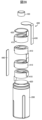
- FIG. 2 is an exploded perspective view for explaining a battery pack housed in the battery module according to the first embodiment.
- FIG. 3 is a cross-sectional view showing an example of the configuration of a single cell.
- FIG. 4 is a perspective view showing an example of the configuration of a single cell used in a battery module.
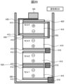
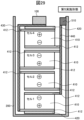
- FIG. 5 is a schematic cross-sectional view for explaining the structure of the battery module according to the first embodiment.
- FIG. 6 is a diagram for explaining the problem.
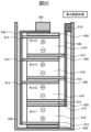
- FIG. 7 is a schematic cross-sectional view for explaining the structure of the battery module of the modification 1A.
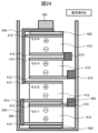
- FIG. 8 is a schematic cross-sectional view for explaining the structure of the battery module of the modified example 1B.
- FIG. 1 is a perspective view showing the appearance of a battery module according to a first embodiment.
- FIG. 2 is an exploded perspective view for explaining a battery pack housed in the battery module according to
- FIG. 9 is a perspective view showing an example of the configuration of a unit cell used in a battery module.
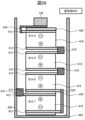
- FIG. 10 is a schematic cross-sectional view for explaining the structure of the battery module of modification 1C.
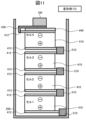
- FIG. 11 is a schematic cross-sectional view for explaining the structure of a battery module according to modification 1D.
- FIG. 12 is a schematic cross-sectional view for explaining the structure of a battery module according to Modification 1E.
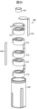
- FIG. 13 is an exploded perspective view for explaining a battery pack housed in a battery module according to the third embodiment.
- FIG. 14 is a perspective view showing an example of the configuration of a unit cell used in a battery module.
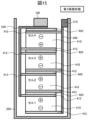
- FIG. 15 is a schematic cross-sectional view for explaining the structure of the battery module according to the third embodiment.
- FIG. 16 is a schematic cross-sectional view for explaining the structure of the battery module of Modification 3A.
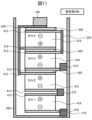
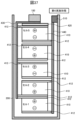
- FIG. 17 is a schematic cross-sectional view for explaining the structure of the battery module of modification 3B.
- FIG. 18 is a perspective view showing an example of the configuration of a single cell used in a battery module.
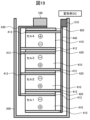
- FIG. 19 is a schematic cross-sectional view for explaining the structure of the battery module of modification 3C.
- FIG. 20 is a schematic cross-sectional view for explaining the structure of a battery module according to modification 3D.
- FIG. 21 is a schematic cross-sectional view for explaining the structure of a battery module according to modification example 3E.
- FIG. 22 is a schematic cross-sectional view for explaining the structure of the battery module according to the fourth embodiment.
- FIG. 23 is a schematic cross-sectional view for explaining the structure of the battery module of Modification 4A.
- FIG. 24 is a schematic cross-sectional view for explaining the structure of the battery module of modification 4B.
- FIG. 25 is a schematic cross-sectional view for explaining the structure of the battery module of modification 4C.
- FIG. 26 is a schematic cross-sectional view for explaining the structure of a battery module according to modification example 4D.
- FIG. 27 is a schematic cross-sectional view for explaining the structure of a battery module of Modification Example 4E.
- FIG. 28 is an exploded perspective view for explaining a battery pack housed in a battery module according to the fifth embodiment.
- FIG. 29 is a schematic cross-sectional view for explaining the structure of the battery module according to the fifth embodiment.
- FIG. 30 is a schematic cross-sectional view for explaining the structure of the battery module of Modification 5A.
- FIG. 31 is a schematic cross-sectional view for explaining the structure of a battery module according to modification 5B.
- FIG. 32 is a schematic cross-sectional view for explaining the structure of the battery module of modification example 5C.
- FIG. 33 is a schematic cross-sectional view for explaining the structure of a battery module according to modification example 5D.
- FIG. 34 is a schematic cross-sectional view for explaining the structure of a battery module of modification example 5E.
- FIG. 35 is a schematic cross-sectional view for explaining the structure of a battery module according to modification example 5F.
- FIG. 36 is an exploded perspective view for explaining a battery pack housed in a battery module according to the sixth embodiment.
- FIG. 37 is a schematic cross-sectional view for explaining the structure of the battery module according to the sixth embodiment.
- FIG. 38 is a schematic cross-sectional view for explaining the structure of a battery module of Modification 6A.
- FIG. 39 is a schematic cross-sectional view for explaining the structure of the battery module of modification example 6B.
- FIG. 40 is a schematic cross-sectional view for explaining the structure of the battery module of modification example 6C.
- FIG. 41 is an exploded perspective view for explaining a battery pack housed in a battery module according to the seventh embodiment.
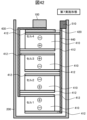
- FIG. 42 is a schematic cross-sectional view for explaining the structure of the battery module according to the seventh embodiment.
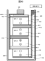
- FIG. 43 is a schematic cross-sectional view for explaining the structure of the battery module of modification 7A.
- FIG. 44 is a schematic cross-sectional view for explaining the structure of the battery module of modification example 7B.
- FIG. 45 is a schematic cross-sectional view for explaining the structure of the battery module of modification example 7C.
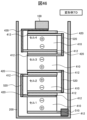
- FIG. 46 is a schematic cross-sectional view for explaining the structure of a battery module of modification example 7D.
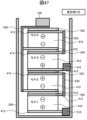
- FIG. 47 is a schematic cross-sectional view for explaining the structure of a battery module of modification example 7E.
- FIG. 48 is a schematic cross-sectional view for explaining the structure of the battery module according to the eighth embodiment.
- FIG. 49 is a schematic cross-sectional view for explaining the structure of the battery module of Modification 8A.
- FIG. 50 is a schematic cross-sectional view for explaining the structure of the battery module of modification 8B.
- FIG. 51 is a schematic cross-sectional view for explaining the structure of the battery module of modification example 8C.
- FIG. 52 is an exploded perspective view for explaining a battery pack housed in a battery module according to the ninth embodiment.
- FIG. 53 is a schematic cross-sectional view for explaining the structure of a battery module according to the ninth embodiment.
- FIG. 54 is a schematic cross-sectional view for explaining the structure of a battery module of modification example 9A.
- FIG. 55 is a schematic cross-sectional view for explaining the structure of the battery module of modification example 9B.
- FIG. 56 is a schematic cross-sectional view for explaining the structure of the battery module of modification example 9C.
- FIG. 57 is a schematic cross-sectional view for explaining the structure of a battery module of modification example 9D.
- FIG. 58 is a schematic cross-sectional view for explaining the structure of a battery module of modification example 9E.
- FIG. 1 is a perspective view showing the appearance of a battery module according to the first embodiment.
- the battery module has a substantially cylindrical shape. It is not limited to a substantially cylindrical shape, and may be a rectangular or other rectangular can shape depending on the product to be mounted.
- the battery module includes a terminal portion or terminal member 100, a cylindrical can or battery can 200, a cap 300 that seals the opening of the cylindrical can 200, and a battery pack 400 (see FIG.
- the cap 300 has an opening penetrating in the thickness direction or the height direction of the battery module, and a part of the terminal member 100 is exposed from the opening.
- the cap 300 is made of, for example, insulating plastic, and has a function of insulating the cylindrical can 200 and the terminal member 100.
- the cylindrical can 200 is, for example, made of metal, has a cylindrical shape including a bottom surface and a side surface extending from the bottom surface in a first direction, and is a case in which the surface facing the bottom surface is open, forming a space in which the assembled battery 400 is housed.
- the first direction is the height direction of the battery module or a direction intersecting the bottom surface.
- the terminal member 100 exposed from the opening of the cap 300 on the top surface functions as a positive electrode terminal
- the cylindrical can 200 functions as a negative electrode terminal
- FIG. 2 is an exploded perspective view for explaining the battery pack 400 housed in the battery module according to the first embodiment.
- the battery pack 400 includes a plurality of single cells 410 (four in this example), a plurality of insulating plates 420, a first power supply plate 430, and a second power supply plate 440.
- the single cell 410 is a cross-sectional view showing an example of the configuration of a single cell 410.
- the single cell 410 includes an electrode body 411, a power supply tab 412 attached to the positive electrode side surface of the electrode body 411, and a power supply tab 412 attached to the negative electrode side surface of the electrode body 411.
- the electrode body 411 is composed of a battery molded body.
- the battery molded body includes a positive electrode side layer 413, a negative electrode side layer 414, and a solid electrolyte layer 415 interposed between the positive electrode side layer 413 and the negative electrode side layer 414.
- the battery molded body has a laminated structure in which the solid electrolyte layer 415 is interposed between the positive electrode side layer 413 and the negative electrode side layer 414.
- the electrode body 411 may be configured such that the battery molded body is covered with an exterior material.
- the positive electrode side layer 413 includes a positive electrode layer 416 and a positive electrode current collector layer 417.
- the positive electrode side layer 413 may be composed of only the positive electrode layer 416, or may include the positive electrode layer 416, the positive electrode current collector layer 417, and other layers having functions other than these layers.
- the positive electrode side layer 413 may include the positive electrode layer 416 and other layers.
- the positive electrode layer 416 is composed of, for example, a molded body of a positive electrode mixture containing a positive electrode active material, a conductive assistant, and a solid electrolyte.
- the positive electrode active material is not particularly limited as long as it is a positive electrode active material used in conventionally known lithium ion secondary batteries, that is, an active material capable of absorbing and releasing Li ions.
- the positive electrode active material include spinel-type lithium manganese composite oxide represented by LiM x Mn 2-x O 4 (wherein M is at least one element selected from the group consisting of Li, B, Mg, Ca, Sr, Ba, Ti, V, Cr, Fe, Co, Ni, Cu, Al, Sn, Sb, In, Nb, Mo, W, Y, Ru, and Rh, and 0.01 ⁇ x ⁇ 0.5), Li x Mn (1-y-x) Ni y M z O (2-k) F l a layered compound represented by LiCo1-xMxO2 (wherein M is at least one element selected from the group consisting of Co, Mg, Al, B, Ti, V, Cr, Fe, Cu, Zn, Zr, Mo, Sn, Ca, Sr, and W , and 0.8 ⁇ x ⁇ 1.2, 0 ⁇ y ⁇ 0.5, 0 ⁇ z ⁇ 0.5, k+l ⁇ 1, -0.1 ⁇ k ⁇ 0.2, 0 ⁇ l ⁇ 0.1); a lithium cobalt composite oxide
- the average particle size of the positive electrode active material is preferably 1 ⁇ m or more, more preferably 2 ⁇ m or more, and is preferably 10 ⁇ m or less, more preferably 8 ⁇ m or less.
- the positive electrode active material may be either primary particles or secondary particles formed by agglomeration of primary particles. When a positive electrode active material with an average particle size in the above range is used, a large interface with the solid electrolyte can be obtained, thereby further improving the load characteristics of the battery.
- the positive electrode active material preferably has a reaction suppression layer on its surface to suppress reaction with the solid electrolyte.
- the solid electrolyte may oxidize and form a resistive layer, which may reduce the ionic conductivity within the molded body.
- the reaction suppression layer may be made of a material that has ion conductivity and can suppress the reaction between the positive electrode active material and the solid electrolyte.
- materials that can form the reaction suppression layer include oxides containing Li and at least one element selected from the group consisting of Nb, P, B, Si, Ge, Ti, and Zr, more specifically, Nb-containing oxides such as LiNbO 3 , Li 3 PO 4 , Li 3 BO 3 , Li 4 SiO 4 , Li 4 GeO 4 , LiTiO 3 , LiZrO 3, etc.
- the reaction suppression layer may contain only one of these oxides, or may contain two or more of them, and further, a plurality of these oxides may form a composite compound. Among these oxides, it is preferable to use an Nb-containing oxide, and it is more preferable to use LiNbO 3 .
- the reaction suppression layer is preferably present on the surface in an amount of 0.1 to 1.0 parts by mass per 100 parts by mass of the positive electrode active material. This range can effectively suppress the reaction between the positive electrode active material and the solid electrolyte.
- Methods for forming a reaction suppression layer on the surface of the positive electrode active material include the sol-gel method, mechanofusion method, CVD method, and PVD method.
- the content of the positive electrode active material in the positive electrode mixture is preferably 60 to 95 mass %.
- Examples of conductive additives for the positive electrode include carbon materials such as graphite (natural graphite, artificial graphite), graphene, carbon black, carbon nanofibers, and carbon nanotubes.
- the content of the conductive additive in the positive electrode mixture is preferably 1 to 10 mass%.
- the solid electrolyte contained in the positive electrode mixture is not particularly limited as long as it has lithium ion conductivity.
- sulfide-based solid electrolytes, hydride-based solid electrolytes, halide-based solid electrolytes, oxide-based solid electrolytes, etc. can be used.
- Examples of sulfide-based solid electrolytes include particles of Li 2 S-P 2 S 5 , Li 2 S-SiS 2 , Li 2 S-P 2 S 5 -GeS 2 , and Li 2 S-B 2 S 3 glass.
- thio-LISICON-type electrolytes Li 10 GeP 2 S 12 , Li 9.54 Si 1.74 P 1.44 S 11.7 Cl 0.3, etc., Li 12-12a-b+c+6d-e M 1 ) have been attracting attention in recent years for their high Li ion conductivity.
- M 1 is Si, Ge or Sn
- M 2 is P or V
- M 3 is Al, Ga, Y or Sb
- M 4 is Zn, Ca or Ba
- M 5 is S or either S or O
- X is F, Cl, Br or I, 0 ⁇ a ⁇ 3, 0 ⁇ b+c+d ⁇ 3, 0 ⁇ e ⁇ 3
- Examples of hydride-based solid electrolytes include LiBH 4 , solid solutions of LiBH 4 and the following alkali metal compounds (for example, those in which the molar ratio of LiBH 4 to the alkali metal compound is 1:1 to 20:1), etc.
- Examples of the alkali metal compounds in the solid solutions include at least one selected from the group consisting of lithium halides (LiI, LiBr, LiF, LiCl, etc.), rubidium halides (RbI, RbBr, RbF, RbCl, etc.), cesium halides (CsI, CsBr, CsF, CsCl, etc.), lithium amide, rubidium amide, and cesium amide.
- lithium halides LiI, LiBr, LiF, LiCl, etc.
- rubidium halides RbI, RbBr, RbF, RbCl, etc.
- cesium halides CsI, CsBr, CsF, Cs
- Other known solid electrolytes that can be used include those described in, for example, WO 2020/070958 and WO 2020/070955.
- oxide-based solid electrolytes examples include garnet-type Li 7 La 3 Zr 2 O 12 , NASICON-type Li 1+O Al 1+O Ti 2-O (PO 4 ) 3 and Li 1+p Al 1+p Ge 2-p (PO 4 ) 3 , and perovskite-type Li 3q La 2/3-q TiO 3 .
- sulfide-based solid electrolytes are preferred due to their high lithium ion conductivity, sulfide-based solid electrolytes containing Li and P are more preferred, and argyrodite-type sulfide-based solid electrolytes, which have particularly high lithium ion conductivity and high chemical stability, are even more preferred.
- the average particle size of the solid electrolyte is preferably 0.1 ⁇ m or more, and more preferably 0.2 ⁇ m or more, from the viewpoint of reducing grain boundary resistance, while it is preferably 10 ⁇ m or less, and more preferably 5 ⁇ m or less, from the viewpoint of forming a sufficient contact interface between the active material and the solid electrolyte.
- the content of the solid electrolyte in the positive electrode mixture is preferably 10 parts by mass or more, and more preferably 30 parts by mass or more, when the content of the positive electrode active material is 100 parts by mass.
- the content of solid electrolyte in the positive electrode mixture is preferably 65 parts by mass or less, and more preferably 60 parts by mass or less, when the content of the positive electrode active material is 100 parts by mass.
- the positive electrode current collector layer 417 can be made of a metal foil such as aluminum or stainless steel, punched metal, mesh, expanded metal, foamed metal, carbon sheet, etc.
- the positive electrode mixture compact can be formed, for example, by compressing the positive electrode mixture prepared by mixing the positive electrode active material, conductive additive, solid electrolyte, and binder added as necessary, by pressure molding or the like.
- the positive electrode mixture compact formed by the above-mentioned method can be attached to the current collector by pressure bonding, or the positive electrode mixture and the current collector can be pressure molded into an integrated compact.
- the thickness of the positive electrode mixture compact (in the case of a positive electrode having a current collector, the thickness of the positive electrode mixture compact per one side of the current collector; the same applies below) is preferably 200 ⁇ m or more from the viewpoint of increasing the capacity of the battery.
- the thickness of the positive electrode mixture compact is usually 2000 ⁇ m or less.
- the negative electrode side layer 414 includes a negative electrode layer 418 and a negative electrode current collector layer 419.
- the negative electrode side layer 414 may be composed of only the negative electrode layer 418, or may include the negative electrode layer 418, the negative electrode current collector layer 419, and other layers having functions other than these layers.
- the negative electrode side layer 414 may include the negative electrode layer 418 and other layers.
- the negative electrode layer 418 is composed of a molded negative electrode mixture that includes, for example, a negative electrode active material, a conductive additive, and a solid electrolyte.
- the negative electrode active material for example, one or a mixture of two or more carbon-based materials capable of absorbing and releasing lithium, such as graphite, pyrolytic carbons, cokes, glassy carbons, fired bodies of organic polymer compounds, mesocarbon microbeads (MCMB), carbon fibers, etc., can be used.
- carbon-based materials capable of absorbing and releasing lithium such as graphite, pyrolytic carbons, cokes, glassy carbons, fired bodies of organic polymer compounds, mesocarbon microbeads (MCMB), carbon fibers, etc.
- simple substances containing elements such as Si, Sn, Ge, Bi, Sb, In, compounds that can be charged and discharged at a low voltage close to that of lithium metal, such as compounds containing lithium-containing nitrides or lithium-containing oxides, lithium metal, and lithium/aluminum alloys can also be used as the negative electrode active material.
- one or a mixture of two or more metal oxides such as Li4Ti5O12 , TiO2 , NbO2.5- ⁇ (0 ⁇ 0.5), MoO3- ⁇ (0 ⁇ 1), WO3- ⁇ (0 ⁇ 1 ) , TiNb2O7 , and metal sulfides such as WS2 and MoS2 can be used as the negative electrode active material.
- the solid electrolyte is not particularly limited as long as it has lithium ion conductivity.
- a sulfide-based solid electrolyte, a hydride-based solid electrolyte, a halide-based solid electrolyte, an oxide-based solid electrolyte, and the like can be used.
- the negative electrode current collector layer 419 can be made of a metal foil such as aluminum or stainless steel, punched metal, mesh, expanded metal, foamed metal, carbon sheet, etc.
- the negative electrode mixture compact can be formed, for example, by compressing the negative electrode mixture prepared by mixing the negative electrode active material, conductive additive, solid electrolyte, and binder added as necessary, by pressure molding or the like.
- the negative electrode mixture compact formed by the above-mentioned method can be attached to the current collector by pressure bonding, or the current collector and the negative electrode mixture can be pressure molded into an integrated compact.
- the thickness of the negative electrode mixture compact (in the case of a negative electrode having a current collector, the thickness of the negative electrode mixture compact per one side of the current collector; the same applies below) is preferably 200 ⁇ m or more from the viewpoint of increasing the capacity of the battery.
- the thickness of the negative electrode mixture compact is usually 2000 ⁇ m or less.
- the solid electrolyte layer 415 includes a solid electrolyte.
- the solid electrolyte may be one or more of the various sulfide-based solid electrolytes, hydride-based solid electrolytes, and oxide-based solid electrolytes exemplified above as those usable in the positive electrode layer.
- the solid electrolyte layer may have a porous body such as a resin nonwoven fabric as a support.
- the solid electrolyte layer 415 can be formed by a method of compressing the solid electrolyte by pressure molding, or a method of applying a solid electrolyte layer forming composition prepared by dispersing the solid electrolyte in a solvent onto a substrate, a positive electrode, or a negative electrode, drying the composition, and performing pressure molding such as pressing as necessary.
- the solvent used in the composition for forming the solid electrolyte layer is preferably one that does not easily deteriorate the solid electrolyte.
- non-polar aprotic solvents such as hydrocarbon solvents such as hexane, heptane, octane, nonane, decane, decalin, toluene, and xylene.
- ultra-dehydrated solvents with a water content of 0.001 mass% (10 ppm) or less.
- fluorine-based solvents such as “Vertrel (registered trademark)” manufactured by Mitsui DuPont Fluorochemicals, “Zeorolla (registered trademark)” manufactured by Nippon Zeon Co., Ltd., and “Novec (registered trademark)” manufactured by Sumitomo 3M Co., Ltd., as well as non-aqueous organic solvents such as dichloromethane and diethyl ether can also be used.
- the thickness of the solid electrolyte layer is preferably 10 to 300 ⁇ m.
- the power supply tab 412 is made of a material having electrical conductivity.
- the power supply tab 412 is, for example, a plate-shaped body made of a material having electrical conductivity such as metal.
- the power supply tab 412 attached to the positive electrode side surface of the single cell 410 functions as a positive electrode terminal of the single cell 410.
- the power supply tab 412 attached to the negative electrode side surface of the single cell 410 functions as a negative electrode terminal of the single cell 410.
- the power supply tab 412 functioning as a positive electrode terminal may also be referred to as a "positive electrode power supply tab 412" or a "first power supply tab".
- the power supply tab 412 functioning as a negative electrode terminal may also be referred to as a "negative electrode power supply tab 412" or a "second power supply tab”.
- the insulating plate 420 is an insulating member having insulating properties.
- the insulating plate 420 is provided for the purpose of ensuring insulation between the members that are interposed by the insulating plate 420.
- the insulating plate 420 may be provided for other purposes, such as stabilizing the posture of the members, even if it is not necessary to ensure insulation between the members that are interposed.
- the insulating plate 420 may be provided for the purpose of ensuring insulation between the opposing surfaces of the unit cells 410 adjacent in the stacking direction, for the purpose of ensuring insulation between the terminal member 100 and the upper surface of the unit cell 410, for the purpose of ensuring insulation between the cylindrical can 200 and the unit cell 410, or for other purposes other than the purpose of ensuring insulation.
- a material having insulating properties such as insulating paper is used.
- the first power supply plate 430 and the second power supply plate 440 are members that electrically connect the single cell 410 (power supply tab 412) to the terminal member 100 or the cylindrical can 200.
- a conductive member is used for the first power supply plate 430 and the second power supply plate 440.
- the first power supply plate 430 and the second power supply plate 440 are, for example, plate-shaped bodies made of a conductive material such as a metal.
- the first power supply plate 430 electrically connects between the terminal member 100 and the positive power supply tab 412.
- the first power supply plate 430 electrically connecting between the terminal member 100 and the positive power supply tab 412 is referred to as the "first power supply plate (positive electrode) 430.”
- the second power supply plate 440 electrically connects between the cylindrical can 200 and the negative power supply tab 412.
- the second power supply plate 440 electrically connecting between the cylindrical can 200 and the negative power supply tab 412 is referred to as the "second power supply plate (negative electrode) 440.”
- the first power supply plate 430 that electrically connects between the terminal member 100 functioning as a negative terminal and the negative power supply tab 412 is referred to as the "first power supply plate (negative electrode) 430.”
- the second power supply plate 440 that electrically connects between the cylindrical can 200 functioning as a positive terminal and the positive power supply tab 412 is referred to as the “second power supply plate (positive electrode) 440.” do.
- the unit cells 410 constituting the assembled battery 400 of the battery module include a type 1 unit cell 410 (hereinafter also referred to as a "type 1 cell”) and a type 2 unit cell 410 (hereinafter also referred to as a "type 2 cell”) shown in FIG. 4.
- the assembled battery 400 of the battery module has one or more type 1 cells and type 2 cells, and when it is composed of one or more type 1 cells, the multiple type 1 cells have the same structure including the bending (bending shape) of the power supply tab 412.
- One type 2 cell differs from the structure of the type 1 cell only in the bending (bending shape) of the power supply tab 412.
- the power supply tab attached to the electrode body of at least one single cell is different from the power supply tab attached to the electrode body of the other single cells, and the difference is the bending shape or the surface where the power supply tab is attached to the electrode body.
- the manufacturing process of the battery module is not limited to the illustrated process.
- the electrode body 411 and the power supply tab 412 are manufactured, the positive power supply tab 412 is attached to the positive electrode side surface of the electrode body 411, the negative power supply tab 412 is attached to the negative electrode side surface of the electrode body 411, and the single cell 410 is manufactured in the first process.
- the process of attaching the power supply tab 412 to the electrode body 411 may not be the first process, but may be the second or third process depending on the manufacturing line.
- Type 1 cells have two power supply tabs 412 that are bent identically.
- the power supply tab 412 has, for example, a substantially rectangular planar shape including two long sides and two short sides.
- the power supply tab 412 used in the type 1 cell is subjected to a first bending process. Specifically, the power supply tab 412 used in the type 1 cell is bent to have a bending shape including a first portion (hereinafter referred to as the "flat portion 412a") and a second portion (hereinafter referred to as the "bent portion 412b”) bent so as to be perpendicular or substantially perpendicular to the flat portion 412a.
- the second portion may also be bent to a predetermined angle with respect to the first portion.
- the positive power supply tab 412 may be a member that electrically connects between the positive electrode side surface of the cell and the power supply plate (positive electrode), and the negative power supply tab 412 may be a member that electrically connects between the negative electrode side surface of the cell and the power supply plate (negative electrode).
- the same bending process means that the bending direction is the same with respect to the connection surface of the single cell. It is described as the same bending process even if the length of the surface connected to the single cell or the length of the bent rising surface differs by a certain amount, for example, 0 to 1 mm, due to component variations and processing variations, or even if the bending angle differs by a certain angle, for example, about ⁇ 10 degrees, due to component variations and processing variations. Alternatively, if the second part is bent to a certain angle with respect to the first part, and the bent angle is within a certain range, it is considered the same bending process.
- a power supply tab 412 i.e., a negative power supply tab 412 is attached to the negative electrode side of the electrode body 411, and a power supply tab 412 (i.e., a positive power supply tab 412) is attached to the positive electrode side of the electrode body 411.
- the negative power supply tab 412 is attached so that the bent surface of the flat portion 412a contacts the negative surface of the electrode body 411.
- the negative power supply tab 412 is joined to the negative surface of the electrode body by welding or the like.
- the bent portion 412b of the negative power supply tab 412 faces the side surface of the electrode body 411. In this case, it is preferable that the length of the bent portion 412b is smaller than the thickness of the electrode body 411 from the viewpoint of avoiding interference with other power supply tabs 412 of the adjacent single cell 410 on the positive surface side.
- the positive electrode power supply tab 412 is attached so that the surface opposite the bent side of the flat portion 412a contacts the positive electrode side surface of the electrode body 411.
- the positive electrode power supply tab 412 is joined to the positive electrode side surface of the electrode body 411 by welding or the like.
- a type 2 cell is provided with one power supply tab 412 that has been subjected to a first bending process that is the same as the power supply tab 412 of a type 1 cell, and one power supply tab 412 that has been subjected to a second bending process that is different from the first bending process.
- One of the power supply tabs 412 used in the type 2 cell is bent to have a second bending process different from the first bending process.
- one of the power supply tabs 412 used in the type 2 cell is bent to have a bending shape including a first portion (flat portion 412a) and a second portion (hereinafter referred to as "bent portion 412b") bent (folded back) to a predetermined position facing a part of the surface opposite to the surface of the flat portion 412a that contacts the electrode body 411.
- this bent portion 412b (bent portion 412b of the positive electrode power supply tab 412 for the type 2 cell) is also referred to as "folded back portion 412c".
- Type 1 cells and Type 2 cells have the same configuration, except for the bending process (bending shape) of the positive electrode power supply tab 412.
- a negative electrode power supply tab 412 is attached to the negative electrode side of the Type 2 cell in the same manner as the Type 1 cell.
- the positive power supply tab 412 is attached so that one side of the flat portion 412a or the side opposite to the bent side of the flat portion 412a contacts the positive electrode side surface of the electrode body 411.
- the positive power supply tab 412 is joined to the positive electrode side surface of the electrode body 411 by welding or the like.
- the folded portion 412c of the positive power supply tab 412 for the type 2 cell is formed by further bending the bent portion 412b for the type 1 cell, so that in the type 2 cell, the only difference between the folded portion 412c and the bent portion 412b compared to the type 1 cell is the bending angle, and the height size is reduced due to the bending angle.
- the power supply tab 412 is attached to the electrode body 411, and in the second step, multiple cells are stacked.
- the stacked multiple cells are stored in a cylindrical can 200. Note that the second and third steps may be combined into one step, and the manufacturing order of the first and second steps may be changed depending on the manufacturing line.
- FIG. 5 As shown in FIG. 5, four unit cells 410 are housed in a stacked state in the cylindrical can 200.
- An insulating plate 420 is disposed between adjacent unit cells 410 in the stacking direction.
- the four single cells 410 may be referred to as cell 1, cell 2, cell 3, and cell 4, in that order from bottom to top.
- cell 1, cell 2, cell 3, and cell 4 When there is no need to distinguish between cell 1, cell 2, cell 3, and cell 4, they will be referred to as "cells.”
- Each cell is contained in the cylindrical can 200 in a state where it is stacked with the positive electrode on top and the negative electrode on the bottom.
- cells 1 to 4 are all contained in the cylindrical can 200 in a state where they are stacked in the same orientation.
- Type 1 cells are used for cells 1 to 3, and only cell 4 uses a "type 2 cell.”
- the positive electrode power supply tabs 412 of cells 1, 2, 3, and 4 are connected to a first power supply plate (positive electrode) 430, and the negative electrode power supply tabs 412 of cells 1, 2, 3, and 4 are connected to a second power supply plate (negative electrode) 440.
- cells 1, 2, 3, and 4 are connected in a four-parallel connection configuration.
- an insulating plate 420 is interposed between the opposing surfaces of adjacent cells in the stacking direction in order to ensure insulation. Note that the negative electrode side surface of cell 1 and the cylindrical can 200 have the same polarity, so insulating plate 420 is not necessary. Alternatively, if the opposing surfaces of the two cells have different polarities, insulating plate 420 must be placed, and if the opposing surfaces of the two cells have the same polarity, insulating plate 420 is not necessary.
- One end of the first power supply plate (positive electrode) 430 is connected to the terminal member 100, and one end of the second power supply plate (negative electrode) 440 is connected to the cylindrical can 200.
- the terminal member 100 functions as a positive electrode terminal, and the cylindrical can 200 functions as a negative electrode terminal.
- the battery module according to the first embodiment can prevent the positive electrode power supply tab 412 of the top cell 4 from interfering with the cap 300 and getting in the way. If all type 1 cells are used for cells 1 to 4, and all of the cells are housed in the cylindrical can 200 in a stacked state with the positive electrode on top and the negative electrode on the bottom, the following problem may occur. That is, as shown in FIG.
- the bent portion 412b of the power supply tab 412 of the top cell 4 indicated by the arrow P1 interferes with the cap 300 and gets in the way.
- only cell 4 is a "type 2 cell” (i.e., a cell in which only the upper power supply tab 412 of the top cell is bent differently) so that the positive power supply tab 412 of the top cell 4 does not interfere with the cap 300 and become a hindrance.
- the battery module when a battery pack 400 is constructed in a parallel connection configuration using a plurality of single cells 410 each having the same electrode body 411 structure, only the top cell is a type 2 cell. That is, the battery module uses a cell in which only the upper power supply tab 412 of the top cell is bent differently (having a different bent shape). This allows the battery module to reduce the size of the battery pack 400 in the height direction. Also, by connecting a plurality of cells in parallel, a large capacity all-solid-state battery can be realized.
- Fig. 7 is a schematic cross-sectional view for illustrating the structure of the battery module of the modified example 1A.
- the type of unit cell 410 used in the battery module of modification 1A is the same as in the first embodiment.
- the orientation of cells 1 to 4 in the battery module of modification 1A is the same as in the first embodiment.
- the negative electrode power supply tab 412 of cell 1 is connected to the cylindrical can 200.
- the positive electrode power supply tab 412 of cell 1 and the negative electrode power supply tab 412 of cell 2 are connected.
- the positive electrode power supply tab 412 of cell 2 and the negative electrode power supply tab 412 of cell 3 are connected.
- the positive electrode power supply tab 412 of cell 3 and the negative electrode power supply tab 412 of cell 4 are connected.
- the positive electrode power supply tab 412 of cell 4 (type 2 cell) is connected to the first power supply plate (positive electrode) 430.
- the insulating plate 420 between them is provided not for the purpose of ensuring insulation but to stabilize the position. This insulating plate 420 may be omitted.
- the battery module of the modified example 1A can reduce the size of the assembled battery 400 in the height direction, as in the first embodiment. Furthermore, in the battery module of the modified example 1A, since the cells 1, 2, 3, and 4 are connected in a serial connection form, it is desired that the opposing surfaces of different polarities between adjacent cells in the stacking direction be in contact (there is no problem even if they are in contact), and therefore there is no need to provide an insulating plate 420 between these cells. Therefore, the battery module of the modified example 1A can be made lighter by reducing the number of members constituting the assembled battery 400. Furthermore, the battery module of the modified example 1A can be made lighter by reducing the size of the first power supply plate (positive electrode) 430 and omitting the second power supply plate 440. In addition, the battery module of the modified example 1A can be made lighter by connecting multiple cells in series.
- Fig. 8 is a schematic cross-sectional view for explaining the structure of the battery module of Modification 1B.
- the type of unit cell 410 used in the battery module of modification 1B is the same as in the first embodiment.
- the orientation of cells 1 to 4 in the battery module of modification 1B is the same as in the first embodiment.
- the second power supply plate 440 is omitted.
- the size of the first power supply plate (positive electrode) 430 and the number of positive power supply tabs 412 connected to the first power supply plate (positive electrode) 430 are different from those in the first embodiment.
- the first power supply plate (positive electrode) 430 only needs to electrically connect between the upper positive power supply tab 412 of the cell 4 and the terminal member 100, and between the upper positive power supply tab 412 of the cell 2 and the terminal member 100, so the size of the first power supply plate (positive electrode) 430 is smaller than that in the first embodiment.
- the power supply tabs 412 are connected to each other and between the power supply tab 412 and the cylindrical can 200 by welding 510.
- the negative power supply tab 412 of cell 1 is connected to the cylindrical can 200.
- the positive power supply tab 412 of cell 1 and the negative power supply tab 412 of cell 2 are connected.
- the positive power supply tab 412 of cell 2 is connected to the first power supply plate (positive electrode) 430.
- the negative power supply tab 412 of cell 3 is connected to the cylindrical can 200.
- the positive power supply tab 412 of cell 3 and the negative power supply tab 412 of cell 4 are connected.
- the positive power supply tab 412 of cell 4 (type 2 cell) is connected to the first power supply plate (positive electrode) 430.
- the height direction size of the assembled battery 400 can be made compact. Furthermore, in the battery module of the modified example 1B, cell 1 and cell 2 are connected in series, and cell 3 and cell 4 are connected in series. Furthermore, the two sets of cells connected in series are connected in parallel (2 series 2 parallel connection). Therefore, in the battery module of the modified example 1B, since it is desired to make the opposing surfaces of different polarities between cells 1 and 2 adjacent to each other in the stacking direction contact each other (there is no problem even if they contact each other), the insulating plate 420 between these cells is not required.
- the battery module of the modified example 1B since it is desired to make the opposing surfaces of different polarities between cells 3 and 4 adjacent to each other in the stacking direction contact each other (there is no problem even if they contact each other), the insulating plate 420 between these cells is not required. Therefore, the battery module of the modified example 1B can reduce the number of components constituting the assembled battery 400, and can be made lighter. Furthermore, the battery module of variant 1B can be made lighter by reducing the size of the first power supply plate (positive electrode) 430 and omitting the second power supply plate 440. In addition, in the battery module of variant 1B, the opposing positive electrode side surface of cell 2 and the negative electrode side surface of cell 3 need to be insulated, so an insulating plate 420 is interposed between them.
- Modification example 1C uses a type 3 unit cell 410 (hereinafter also referred to as a "type 3 cell”) shown in Fig. 9 and a type 4 unit cell 410 (hereinafter also referred to as a "type 4 cell”) that has been bent differently from the type 3 cell.
- type 3 cell hereinafter also referred to as a "type 3 cell”
- type 4 cell hereinafter also referred to as a "type 4 cell”
- the Type 3 cell has the same configuration as the Type 1 cell with only the electrode body 411 inverted upside down.
- the Type 4 cell has the same configuration as the Type 2 cell with only the electrode body 411 inverted upside down.
- a power supply tab 412 i.e., positive power supply tab 412 is attached to the positive electrode side surface of the electrode body 411, and a power supply tab 412 (i.e., negative power supply tab 412) is attached to the negative electrode side surface of the electrode body 411.
- the positive power supply tab 412 is attached so that the curved surface of the flat portion 412a contacts the positive electrode side surface of the electrode body 411.
- the positive power supply tab 412 is joined by welding or the like to the positive electrode side surface of the electrode body 411.
- the negative power supply tab 412 is attached so that the surface opposite to the curved side of the flat portion 412a contacts the negative electrode side surface of the electrode body 411.
- the negative power supply tab 412 is joined by welding or the like to the negative electrode side surface of the electrode body 411.
- a type 4 cell is provided with one power supply tab 412 that has been subjected to a first bending process that is the same as the power supply tab 412 of a type 3 cell, and one power supply tab 412 that has been subjected to a second bending process that is different from the first bending process.
- One of the power supply tabs 412 used in the type 4 cell is bent to have a bent shape including a first portion (flat portion 412a) and a second portion (bent portion 412b) bent (folded back) to a position facing a part of the surface on the opposite side of the surface of the flat portion 412a that contacts the electrode body 411.
- This bent portion 412b (bent portion 412b of the negative electrode power supply tab 412 for the type 4 cell) is also called the "folded back portion 412c.” That is, the power supply tab 412 used in the type 3 cell is further bent in the direction of the arrow to become the power supply tab 412 used in the type 4 cell. Therefore, the type 3 cell and the type 4 cell are cells having the same configuration except for the bending (bending shape) of the negative electrode power supply tab 412.
- a positive power supply tab 412 is attached to the positive electrode surface of a Type 4 cell in the same manner as a Type 3 cell.
- the negative power supply tab 412 is attached so that the surface opposite the bent side of the flat portion 412a contacts the negative surface of the electrode body 411.
- the negative power supply tab 412 is joined to the negative surface of the electrode body 411 by welding or the like.
- the folded portion 412c of the negative power supply tab 412 of the type 4 cell is formed by further bending the bent portion 412b of the type 3 cell, so that the height of the type 4 cell is reduced compared to the type 3 cell.
- the negative electrode power supply tabs 412 of cells 1, 2, 3, and 4 are connected to a first power supply plate (negative electrode) 430, and the positive electrode power supply tabs 412 of cells 1, 2, 3, and 4 are connected to a second power supply plate (positive electrode) 440.
- cells 1, 2, 3, and 4 are connected in a 4-parallel connection configuration.
- One end of the first power supply plate (negative electrode) 430 is connected to the terminal member 100, and one end of the second power supply plate (positive electrode) 440 is connected to the cylindrical can 200.
- the terminal member 100 functions as a negative electrode terminal, and the cylindrical can 200 functions as a positive electrode terminal.
- the battery module of variant 1C provides the same effects as the first embodiment.
- the type of unit cell 410 used in the battery module of variant 1D is the same as that of variant 1C.
- the orientation of cells 1 to 4 in the battery module of variant 1D is the same as that of variant 1C.
- modification 1D the second power supply plate 440 is omitted.
- modification 1D differs from modification 1C in the size of the first power supply plate (negative electrode) 430 and the number of negative power supply tabs 412 connected to the first power supply plate (negative electrode) 430.
- the first power supply plate (negative electrode) 430 only needs to electrically connect between the upper negative power supply tab 412 of the cell 4 and the terminal member 100, so the size of the first power supply plate (negative electrode) 430 is smaller than that of modification 1C.
- the power supply tabs 412 are connected to each other and between the power supply tab 412 and the cylindrical can 200 by welding 510.
- the positive electrode power supply tab 412 of cell 1 is connected to the cylindrical can 200.
- the negative electrode power supply tab 412 of cell 1 is connected to the positive electrode power supply tab 412 of cell 2.
- the negative electrode power supply tab 412 of cell 2 is connected to the positive electrode power supply tab 412 of cell 3.
- the negative electrode power supply tab 412 of cell 3 is connected to the positive electrode power supply tab 412 of cell 4.
- the negative electrode power supply tab 412 of cell 4 (type 4 cell) is connected to the first power supply plate (negative electrode) 430.
- One end of the first power supply plate (negative electrode) 430 is connected to the terminal member 100, and the positive electrode power supply tab 412 of the first cell is connected to the cylindrical can 200.
- the terminal member 100 functions as the negative electrode terminal
- the cylindrical can 200 functions as the positive electrode terminal.
- the battery module of variant 1D has the same effect as variant 1A.
- the type of unit cell 410 used in the battery module of variant 1E is the same as in variant 1C.
- the orientation of cells 1 to 4 in the battery module of variant 1E is the same as in variant 1C.
- the size of the first power supply plate (negative electrode) 430 and the number of negative power supply tabs 412 connected to the first power supply plate (negative electrode) 430 are different from modification 1C.
- the first power supply plate (negative electrode) 430 only needs to electrically connect between the upper negative power supply tab 412 of cell 4 and the terminal member 100, and between the upper negative power supply tab 412 of cell 2 and the terminal member 100, so the size of the first power supply plate (negative electrode) 430 is smaller than that of modification 1C.
- the power supply tabs 412 are connected to each other and between the power supply tab 412 and the cylindrical can 200 by welding 510.
- the positive power supply tab 412 of cell 1 is connected to the cylindrical can 200.
- the negative power supply tab 412 of cell 1 and the positive power supply tab 412 of cell 2 are connected.
- the negative power supply tab 412 of cell 2 is connected to the first power supply plate (negative electrode) 430.
- the positive power supply tab 412 of cell 3 is connected to the cylindrical can 200.
- the negative power supply tab 412 of cell 3 and the positive power supply tab 412 of cell 4 are connected.
- the negative power supply tab 412 of cell 4 (type 4 cell) is connected to the first power supply plate (negative electrode) 430.
- One end of the first power supply plate (negative electrode) 430 is connected to the terminal member 100, and the positive electrode power supply tab 412 of the first cell and the positive electrode power supply tab 412 of the third cell are connected to the cylindrical can 200.
- the terminal member 100 functions as the negative electrode terminal
- the cylindrical can 200 functions as the positive electrode terminal.
- the battery module of variant 1E has the same effect as variant 1B.
- a battery module according to a second embodiment of the present invention will be described below.
- the battery module according to the second embodiment differs from the battery module according to the first embodiment shown in FIG.
- the battery module according to the second embodiment uses a type 4 cell as shown in FIG. 9 for the bottommost cell 1.
- the type 4 cell is placed on the bottom surface of the cylindrical can 200 with the positive electrode on top and the negative electrode on the bottom. That is, the type 4 cell is placed on the bottom surface of the cylindrical can 200 in a state in which the state shown in FIG. 9 is turned upside down.
- the other cells 2 to 4 use type 3 cells.
- the type 3 cells are stacked with the positive electrode on top and the negative electrode on the bottom. That is, the type 3 cells are stacked in a state in which the state shown in FIG. 9 is turned upside down.
- the battery module when a plurality of single cells 410 having the same electrode body 411 structure are used to configure a parallel-connected battery pack 400, only the bottom cell is a Type 4 cell. That is, the battery module uses a cell in which only the lower power supply tab 412 of the bottom cell is bent differently (has a different bent shape). This allows the battery module to make the height of the battery pack 400 compact.
- ⁇ Modification 2A>> A description will be given of a modified example 2A of the battery module according to the second embodiment.
- the battery module of the modified example 2A has a structure different from that of the battery module of the modified example 1A shown in FIG.
- the battery module of variant 2A uses a type 4 cell for the bottom cell 1.
- the type 4 cell is arranged on the inside bottom surface of the cylindrical can 200 with the positive electrode on top and the negative electrode on the bottom.
- the remaining cells 2 to 4 use type 3 cells.
- the type 3 cells are stacked with the positive electrode on top and the negative electrode on the bottom.
- the battery module of variant 2A can reduce the height of the assembled battery 400. Furthermore, in the battery module of variant 2A, cells 1, 2, 3, and 4 are connected in a serial connection configuration, and therefore it is desired that the opposing faces of different polarities between adjacent cells in the stacking direction be in contact (as there is no problem with them being in contact), so there is no need to provide insulating plates 420 between these cells. Therefore, the battery module of variant 2A can be made lighter by reducing the number of components that make up the assembled battery 400.
- ⁇ Modification 2B>> A description will be given of a modified example 2B of the battery module according to the second embodiment.
- the battery module of the modified example 2B has a structure different from that of the battery module of the modified example 1B shown in FIG.
- the battery module of variant 2B uses a type 4 cell for the bottom cell 1, similar to variant 2B.
- the type 4 cell is placed on the bottom surface of the cylindrical can 200 with the positive electrode on top and the negative electrode on the bottom.
- Type 3 cells are used for the other cells 2 to 4.
- the type 3 cells are stacked with the positive electrode on top and the negative electrode on the bottom.
- the battery module of the modified example 2B can make the height direction size of the assembled battery 400 compact, as in the second embodiment. Furthermore, in the battery module of the modified example 2B, cell 1 and cell 2 are connected in series, and cell 3 and cell 4 are connected in series. Furthermore, the two sets of cells connected in series are connected in parallel. Therefore, in the battery module of the modified example 2B, since it is desired to make the opposing surfaces of different polarities between cells 1 and 2 adjacent to each other in the stacking direction contact each other (because there is no problem with them contacting each other), the insulating plate 420 between these cells is not required.
- the battery module of the modified example 2B since it is desired to make the opposing surfaces of different polarities between cells 3 and 4 adjacent to each other in the stacking direction contact each other (because there is no problem with them contacting each other), the insulating plate 420 between these cells is not required. Therefore, the battery module of the modified example 2A can reduce the number of members constituting the assembled battery 400, and can be made lighter. Furthermore, in the battery module of the modified example 2B, the size of the first power supply plate 430 is reduced and the second power supply plate 440 is omitted, and therefore the weight can be reduced accordingly. In addition, in the battery module of variant 2B, the opposing positive electrode side surface of cell 2 and the negative electrode side surface of cell 3 need to be insulated, so an insulating plate 420 is interposed between them.
- ⁇ Modification 2C>> A description will be given of a modified example 2C of the battery module according to the second embodiment.
- the battery module of the modified example 2C has a structure different from that of the battery module of the modified example 1C shown in FIG.
- the battery module of variant 2C uses a type 2 cell for the bottom cell 1.
- the type 2 cell is placed on the bottom surface of the cylindrical can 200 with the positive electrode on the bottom and the negative electrode on the top. That is, the type 2 cell is placed on the bottom surface of the cylindrical can 200 in a state in which the state shown in FIG. 4 is turned upside down.
- the other cells 2 to 4 use type 1 cells.
- the type 1 cells are stacked with the positive electrode on the bottom and the negative electrode on the top. That is, the type 1 cells are stacked in a state in which the state shown in FIG. 4 is turned upside down.
- the battery module of variant 2C provides the same effects as the second embodiment.
- ⁇ Modification 2D>> A description will be given of a modified example 2D of the battery module according to the second embodiment.
- the battery module of the modified example 2D has a structure different from that of the battery module of the modified example 1D shown in FIG.
- the battery module of variant 2D uses a type 2 cell for the bottom cell 1.
- the type 2 cell is placed on the bottom surface of the cylindrical can 200 with the positive electrode on the bottom and the negative electrode on the top.
- the other cells 2 to 4 use type 1 cells.
- the type 1 cells are stacked with the positive electrode on the bottom and the negative electrode on the top.
- the battery module of variant 2D has the same effect as variant 2A.
- ⁇ Modification 2E>> A description will be given of a modified example 2E of the battery module according to the second embodiment.
- the battery module of the modified example 2E has a structure different from that of the battery module of the modified example 1E shown in FIG.
- the battery module of variant 2E uses a type 2 cell for the bottom cell 1.
- the type 2 cell is placed on the bottom surface of the cylindrical can 200 with the positive electrode on the bottom and the negative electrode on the top.
- Type 1 cells are used for the other cells 2 to 4.
- the type 1 cells are stacked with the positive electrode on the bottom and the negative electrode on the top.
- the battery module of variant 2E has the same effect as variant 2B.
- Fig. 13 is an exploded perspective view for explaining a battery pack 400 housed in the battery module according to the third embodiment. As shown in Fig. 13, in the battery module according to the third embodiment, only the uppermost unit cell 410 is inverted upside down and oriented in the opposite direction to the orientation of the other unit cells 410.
- the battery module according to the third embodiment uses a type 1 cell shown in FIG. 14 and a type 5 single cell 410 (hereinafter referred to as a "type 5 cell").
- the type 5 cell is the same as the type 1 cell, except that the positive electrode power supply tab 412 is rotated horizontally by 45 degrees and then inverted upside down and attached to the positive electrode surface of the electrode body 411.
- FIG. 15 is a schematic cross-sectional view for explaining the structure of a battery module according to the third embodiment.
- cells 1 to 3 are all stacked in the same orientation (positive electrode on top, negative electrode on bottom), with cell 4 being the only cell that is stacked in a different orientation (positive electrode on bottom, negative electrode on top) and housed in a cylindrical can 200.
- Cells 1 to 3 are "Type 1 cells", and only cell 4 is a "Type 5 cell”.
- the positive electrode power supply tabs 412 of cells 1, 2, 3, and 4 are connected to a first power supply plate (positive electrode) 430, and the negative electrode power supply tabs 412 of cells 1, 2, 3, and 4 are connected to a second power supply plate (negative electrode) 440.
- cells 1, 2, 3, and 4 are connected in a four-parallel connection configuration.
- cells 1 to 4 are arranged such that the positive electrode power supply tabs 412 of cells 1 to 3 overlap in the stacking direction, only the positive electrode power supply tab 412 of cell 4 does not overlap in the stacking direction, and the negative electrode power supply tabs 412 of cells 1 to 4 overlap in the stacking direction.
- the first power supply plate (positive electrode) 430 is shaped so that it can contact the positive electrode power supply tabs 412 of cells 1 to 3 that overlap in the stacking direction, and can contact the positive electrode power supply tab 412 of cell 4 that does not overlap in the stacking direction.
- the first power supply plate (positive electrode) 430 is shaped to include a rectangular first portion that contacts the positive electrode power supply tabs 412 of cells 1 to 3 that overlap in the stacking direction, and a rectangular second portion that contacts the positive electrode power supply tab 412 of cell 4 that does not overlap in the stacking direction. This shape allows the positive electrode power supply tabs 412 of cells 1, 2, 3, and 4 to be connected to the first power supply plate (positive electrode) 430, even if the positive electrode power supply tab 412 of cell 4 alone does not overlap in the stacking direction.
- an insulating plate 420 is interposed between the opposing surfaces of adjacent cells in the stacking direction in order to ensure insulation. Note that the polarity of the bottom surface of cell 4 and the cylindrical can 200 is the same, so the insulating plate 420 is not necessary. Also, the polarity between the third cell and the fourth cell is the same, so the insulating plate 420 may be omitted. If the insulating plate 420 is omitted, the battery module can be made lighter accordingly. If an insulating plate 420 is provided, it is provided for the purpose of stabilizing the position of the members.
- One end of the first power supply plate (positive electrode) 430 is connected to the terminal member 100, and one end of the second power supply plate (negative electrode) 440 is connected to the cylindrical can 200.
- the terminal member 100 functions as a positive electrode terminal, and the cylindrical can 200 functions as a negative electrode terminal.
- Fig. 16 is a schematic cross-sectional view for illustrating the structure of the battery module of the modified example 3A.
- the type of unit cell 410 used in the battery module of modification 3A is the same as in the third embodiment.
- the orientation of cells 1 to 4 in the battery module of modification 3A is the same as in the third embodiment.
- the second power supply plate 440 is omitted.
- the size of the first power supply plate (positive electrode) 430 and the number of positive power supply tabs 412 connected to the first power supply plate (positive electrode) 430 are different from those in the third embodiment.
- the first power supply plate (positive electrode) 430 only needs to electrically connect the positive power supply tab 412 on the lower side of the cell 4 to the terminal member 100, so the size of the first power supply plate (positive electrode) 430 is smaller than that in the third embodiment.
- the power supply tabs 412 are connected to each other and to the cylindrical can 200 by welding 510.
- a tab connection plate 520 is used to electrically connect the power supply tabs 412.
- the negative electrode power supply tab 412 of cell 1 is connected to the cylindrical can 200.
- the positive electrode power supply tab 412 of cell 1 and the negative electrode power supply tab 412 of cell 2 are connected.
- the positive electrode power supply tab 412 of cell 2 and the negative electrode power supply tab 412 of cell 3 are connected.
- the positive electrode power supply tab 412 of cell 3 and the negative electrode power supply tab 412 of cell 4 are connected via a tab connection plate 520.
- the positive electrode power supply tab 412 of cell 4 is connected to the first power supply plate (positive electrode) 430.
- the battery module of the modified example 3A can make the height direction size of the assembled battery 400 compact. Furthermore, in the battery module of the modified example 3A, since cells 1, 2, 3, and 4 are connected in a serial connection form, it is desired that the opposing surfaces of different polarities between adjacent cells in the stacking direction be in contact (as there is no problem with them being in contact), and therefore there is no need to provide an insulating plate 420 between these cells. Therefore, the battery module of the modified example 3A can reduce the number of components constituting the assembled battery 400, and therefore can be made lighter. Furthermore, the battery module of the modified example 3A can be made lighter by reducing the size of the first power supply plate (positive electrode) 430 and omitting the second power supply plate 440.
- Fig. 17 is a schematic cross-sectional view for illustrating the structure of the battery module of Modification 3B.
- the type of unit cell 410 used in the battery module of modification 3B is the same as in the third embodiment.
- the orientation of cells 1 to 4 in the battery module of modification 3B is the same as in the third embodiment.
- the second power supply plate 440 is omitted.
- the size of the first power supply plate (positive electrode) 430 and the number of positive electrode power supply tabs 412 connected to the first power supply plate (positive electrode) 430 are different from those in the third embodiment.
- the first power supply plate (positive electrode) 430 only needs to electrically connect between the lower positive electrode power supply tab 412 of cell 4 and the terminal member 100, and between the upper positive electrode power supply tab 412 of cell 2 and the terminal member 100, so the size of the first power supply plate (positive electrode) 430 is smaller than that in the third embodiment.
- the power supply tabs 412 are connected to each other and to the cylindrical can 200 by welding 510.
- Variation 3B uses a tab connection plate 520 to electrically connect the power supply tabs 412 to each other.
- the negative power supply tab 412 of cell 1 is connected to the cylindrical can 200.
- the positive power supply tab 412 of cell 1 and the negative power supply tab 412 of cell 2 are connected.
- the positive power supply tab 412 of cell 2 is connected to the first power supply plate (positive electrode) 430.
- the negative power supply tab 412 of cell 3 is connected to the cylindrical can 200.
- the positive power supply tab 412 of cell 3 and the negative power supply tab 412 of cell 4 are connected via a tab connection plate 520.
- the positive power supply tab 412 of cell 4 (type 5 cell) is connected to the first power supply plate (positive electrode) 430.
- the height direction size of the assembled battery 400 can be made compact, as in the third embodiment. Furthermore, in the battery module of the modified example 3B, cell 1 and cell 2 are connected in series, and cell 3 and cell 4 are connected in series. Furthermore, the two sets of cells connected in series are connected in parallel (2 series 2 parallel connection). Therefore, in the battery module of the modified example 3B, since it is desired to make the opposing surfaces of different polarities between the adjacent cells 1 and 2 in the stacking direction contact (there is no problem even if they are in contact), the insulating plate 420 between these cells is not necessary. Therefore, the number of components of the battery module of the modified example 3B can be reduced, and the weight can be reduced.
- the size of the first power supply plate 430 is reduced, and the tab connection plate 520 smaller than the second power supply plate 440 is used instead of the second power supply plate 440, and the weight can be reduced accordingly.
- the opposing positive electrode side surface of cell 2 and the negative electrode side surface of cell 3 need to be insulated, so an insulating plate 420 is interposed between them.
- Modification 3C>> A description will be given of a modified example 3C of the battery module according to the third embodiment.
- Modification example 3C uses a type 3 cell shown in Fig. 18 and a type 6 single cell 410 (hereinafter also referred to as a "type 6 cell").
- the Type 6 cell is the same as the Type 3 cell, except that the negative power supply tab 412 is rotated horizontally by 45 degrees and then inverted upside down and attached to the negative surface of the electrode body 411.
- the Type 6 cell has the same configuration as the Type 5 cell, except that only the electrode body 411 is inverted upside down.
- FIG. 19 is a schematic cross-sectional view for explaining the structure of the battery module of variant 3C.
- cells 1 to 3 are all stacked in the same orientation (positive electrode on the bottom, negative electrode on the top) with only cell 4 being stacked in a different orientation (positive electrode on the top, negative electrode on the bottom) and housed in a cylindrical can 200.
- Type 3 cells are used for cells 1 to 3, and type 6 cell is used for cell 4.
- the negative power supply tabs 412 of cells 1, 2, 3, and 4 are connected to a first power supply plate (negative electrode) 430, and the positive power supply tabs 412 of cells 1, 2, 3, and 4 are connected to a second power supply plate (positive electrode) 440.
- cells 1, 2, 3, and 4 are connected in a 4-parallel connection configuration.
- an insulating plate 420 is interposed between the opposing surfaces of adjacent cells with different polarities in the stacking direction in order to ensure insulation. Note that the bottom surface of cell 4 and the cylindrical can 200 have the same polarity, so insulating plate 420 is not necessary. Furthermore, since the polarity between cell 3 and cell 4 is the same, insulating plate 420 may be omitted.
- the type of unit cell 410 used in the battery module of variant 3D is the same as in variant 3C.
- the orientation of cells 1 to 4 in the battery module of variant 3D is the same as in variant 3C.
- the second power supply plate 440 is omitted.
- the size of the first power supply plate (negative electrode) 430 and the number of negative power supply tabs 412 connected to the first power supply plate (negative electrode) 430 are different from those of the modified example 3C.
- the first power supply plate (negative electrode) 430 only needs to electrically connect between the negative power supply tab 412 on the lower side of the cell 4 and the terminal member 100, so the size of the first power supply plate (negative electrode) 430 is smaller than that of the modified example 3C.
- the power supply tabs 412 are connected to each other and between the power supply tab 412 and the cylindrical can 200 by welding 510.
- the modified example 3D uses a tab connection plate 520 to electrically connect between the power supply tabs 412.
- the positive power supply tab 412 of cell 1 is connected to the cylindrical can 200.
- the negative power supply tab 412 of cell 1 is connected to the positive power supply tab 412 of cell 2.
- the negative power supply tab 412 of cell 2 is connected to the positive power supply tab 412 of cell 3.
- the negative power supply tab 412 of cell 3 is connected to the positive power supply tab 412 of cell 4 via a tab connection plate 520.
- the negative power supply tab 412 of cell 4 (type 6 cell) is connected to the first power supply plate (negative electrode) 430.
- the battery module of variant 3D has the same effect as variant 3A.
- the type of unit cell 410 used in the battery module of variant 3E is the same as in variant 3C.
- the orientation of cells 1 to 4 in the battery module of variant 3E is the same as in variant 3C.
- the second power supply plate 440 is omitted.
- the size of the first power supply plate (negative electrode) 430 and the number of negative power supply tabs 412 connected to the first power supply plate (negative electrode) 430 are different from those in the modified example 3C.
- the first power supply plate (negative electrode) 430 only needs to electrically connect between the lower negative power supply tab 412 of the cell 4 and the terminal member 100, and between the upper negative power supply tab 412 of the cell 2 and the terminal member 100, so the size of the first power supply plate (negative electrode) 430 is smaller than that of the modified example 3C.
- the power supply tabs 412 are connected to each other and between the power supply tab 412 and the cylindrical can 200 by welding 510.
- a tab connection plate 520 is used to electrically connect between the power supply tabs 412.
- the positive electrode power supply tab 412 of cell 1 is connected to the cylindrical can 200.
- the negative electrode power supply tab 412 of cell 1 and the positive electrode power supply tab 412 of cell 2 are connected.
- the negative electrode power supply tab 412 of cell 2 is connected to the first power supply plate (negative electrode) 430.
- the positive electrode power supply tab 412 of cell 3 is connected to the cylindrical can 200.
- the negative electrode power supply tab 412 of cell 3 and the positive electrode power supply tab 412 of cell 4 are connected via the tab connection plate 520.
- the negative electrode power supply tab 412 of cell 4 (type 6 cell) is connected to the first power supply plate (negative electrode) 430.
- One end of the first power supply plate (negative electrode) 430 is connected to the terminal member 100, and the positive electrode power supply tab 412 of the first cell and the positive electrode power supply tab 412 of the third cell are connected to the cylindrical can 200.
- the terminal member 100 functions as the negative electrode terminal
- the cylindrical can 200 functions as the positive electrode terminal.
- the battery module of variant 3E has the same effect as variant 3B.
- Fig. 22 is a schematic cross-sectional view for explaining the structure of the battery module according to the fourth embodiment.
- cells 2 to 4 are all stacked in the same orientation (positive electrode on top, negative electrode on bottom), and only cell 1 is stacked in a different orientation (positive electrode on bottom, negative electrode on top) and housed in a cylindrical can 200.
- the battery module according to the fourth embodiment uses type 3 cells shown in Fig. 9 for cells 2 to 4, and type 4 cells for cell 1.
- an insulating plate 420 is interposed between the opposing surfaces of adjacent cells in the stacking direction in order to ensure insulation.
- the bottom surface of cell 4 and the cylindrical can 200 have different polarities, so an insulating plate 420 is interposed between them.
- the polarity between the third cell and the fourth cell is the same, so the insulating plate 420 may be omitted. If the insulating plate 420 is omitted, the battery module can be made lighter accordingly. If an insulating plate 420 is provided, it is provided for the purpose of stabilizing the position of the members.
- One end of the first power supply plate (positive electrode) 430 is connected to the terminal member 100, and one end of the second power supply plate (negative electrode) 440 is connected to the cylindrical can 200.
- the terminal member 100 functions as a positive electrode terminal, and the cylindrical can 200 functions as a negative electrode terminal.
- Fig. 23 is a schematic cross-sectional view for illustrating the structure of the battery module of the modified example 4A.
- the type of unit cell 410 used in the battery module of modification 4A is the same as in the fourth embodiment.
- the orientation of cells 1 to 4 in the battery module of modification 4A is the same as in the fourth embodiment.
- the second power supply plate 440 is omitted. Also, in modification 4A, the size of the first power supply plate (positive electrode) 430 and the number of positive power supply tabs 412 connected to the first power supply plate (positive electrode) 430 are different from those in the fourth embodiment.
- the first power supply plate (positive electrode) 430 only needs to electrically connect between the positive power supply tab 412 on the upper side of the cell 4 and the terminal member 100, so the size of the first power supply plate (positive electrode) 430 is smaller than that in the fourth embodiment.
- the power supply tabs 412 are connected to each other and to the cylindrical can 200 by welding 510.
- Variation 4A uses a tab connection plate 520 to electrically connect the power supply tabs 412 to each other.
- the negative power supply tab 412 of cell 1 is connected to the cylindrical can 200.
- the positive power supply tab 412 of cell 1 and the negative power supply tab 412 of cell 2 are connected via a tab connection plate 520.
- the positive power supply tab 412 of cell 2 and the negative power supply tab 412 of cell 3 are connected.
- the positive power supply tab 412 of cell 3 and the negative power supply tab 412 of cell 4 are connected.
- the positive power supply tab 412 of cell 4 is connected to the first power supply plate (positive electrode) 430.
- cells 1, 2, 3, and 4 are connected in a four-series connection configuration.
- the battery module of variant 4A can make the height direction size of the assembled battery 400 compact. Furthermore, in the battery module of variant 4A, cells 1, 2, 3, and 4 are connected in a serial connection form, so that it is desired that the opposing faces of different polarities between adjacent cells in the stacking direction be in contact (as there is no problem with them being in contact), and therefore there is no need to provide an insulating plate 420 between these cells. Therefore, the battery module of variant 4A can reduce the number of components that make up the assembled battery 400, and therefore can be made lighter. Furthermore, the battery module of variant 4A can reduce the size of the first power supply plate 430, and therefore can be made lighter accordingly.
- Fig. 24 is a schematic cross-sectional view for illustrating the structure of the battery module of the modified example 4B.
- the type of unit cell 410 used in the battery module of modification 4B is the same as in the fourth embodiment.
- the orientation of cells 1 to 4 in the battery module of modification 4B is the same as in the fourth embodiment.
- the negative power supply tab 412 of cell 1 is connected to the cylindrical can 200.
- the positive power supply tab 412 of cell 1 and the negative power supply tab 412 of cell 2 are connected via a tab connection plate 520.
- the positive power supply tab 412 of cell 2 is connected to the first power supply plate (positive electrode) 430.
- the negative power supply tab 412 of cell 3 is connected to the cylindrical can 200.
- the positive power supply tab 412 of cell 3 and the negative power supply tab 412 of cell 4 are connected.
- the positive power supply tab 412 of cell 4 is connected to the first power supply plate (positive electrode) 430.
- the height direction size of the assembled battery 400 can be made compact, as in the fourth embodiment. Furthermore, in the battery module of the modified example 4B, cell 1 and cell 2 are connected in series, and cell 3 and cell 4 are connected in series. Furthermore, the two sets of cells connected in series are connected in parallel (2 series 2 parallel connection). In the battery module of the modified example 4B, since it is desired to make the opposing surfaces of different polarities between the adjacent cells 3 and 4 in the stacking direction contact (there is no problem even if they are in contact), the insulating plate 420 between these cells is not necessary. Therefore, the battery module of the modified example 4B can reduce the number of components, and can be made lighter.
- the battery module of the modified example 4B reduces the size of the first power supply plate 430, and uses the tab connection plate 520 smaller than the second power supply plate 440 instead of the second power supply plate 440, and can be made lighter accordingly.
- the opposing negative electrode surfaces of cell 1 and cell 2 need to be insulated, so an insulating plate 420 is interposed between them.
- Modified example 4C uses type 1 cells and type 5 cells shown in FIG.
- FIG. 25 is a schematic cross-sectional view for explaining the structure of the battery module of variant 4C.
- cells 2 to 4 are all stacked in the same orientation (positive electrode on the bottom, negative electrode on the top) with cell 1 being the only cell stacked in a different orientation (positive electrode on the top, negative electrode on the bottom) and housed in a cylindrical can 200.
- Type 1 cells are used for cells 2 to 4, and type 5 cell is used for cell 1.
- the negative electrode power supply tabs 412 of cells 1, 2, 3, and 4 are connected to a first power supply plate (negative electrode) 430, and the positive electrode power supply tabs 412 of cells 1, 2, 3, and 4 are connected to a second power supply plate (positive electrode) 440.
- cells 1, 2, 3, and 4 are connected in a four-parallel connection configuration.
- One end of the first power supply plate (negative electrode) 430 is connected to the terminal member 100, and one end of the second power supply plate (positive electrode) 440 is connected to the cylindrical can 200.
- the terminal member 100 functions as a negative electrode terminal, and the cylindrical can 200 functions as a positive electrode terminal.
- an insulating plate 420 is interposed between the opposing surfaces of adjacent cells in the stacking direction in order to ensure insulation. Note that the bottom surface of cell 4 and the cylindrical can 200 have different polarities, so an insulating plate 420 is interposed between them. Furthermore, since the polarities between cell 1 and cell 2 are the same, the insulating plate 420 may be omitted.
- the battery module of variant 4C provides the same effects as the fourth embodiment.
- Fig. 26 is a schematic cross-sectional view for illustrating the structure of the battery module of the modified example 4D.
- the type of unit cell 410 used in the battery module of variant 4D is the same as that of variant 4C.
- the orientation of cells 1 to 4 in the battery module of variant 4D is the same as that of variant 4C.
- modification 4D the second power supply plate (negative electrode) 440 is omitted.
- modification 4D differs from modification 4C in the size of the first power supply plate (negative electrode) 430 and the number of negative power supply tabs 412 connected to the first power supply plate (negative electrode) 430.
- the first power supply plate (negative electrode) 430 only needs to electrically connect between the upper negative power supply tab 412 of the cell 4 and the terminal member 100, so the size of the first power supply plate (negative electrode) 430 is smaller than that of modification 4C.
- Modification 4D uses a tab connection plate 520 to electrically connect between the power supply tabs 412.
- the positive power supply tab 412 of cell 1 is connected to the cylindrical can 200.
- the negative power supply tab 412 of cell 1 and the positive power supply tab 412 of cell 2 are connected via a tab connection plate 520.
- the negative power supply tab 412 of cell 2 and the positive power supply tab 412 of cell 3 are connected.
- the negative power supply tab 412 of cell 3 and the positive power supply tab 412 of cell 4 are connected.
- the negative power supply tab 412 of cell 4 is connected to the first power supply plate (positive electrode) 430.
- cells 1, 2, 3, and 4 are connected in a four-series connection configuration.
- the battery module of variant 4D has the same effect as variant 4A.
- Fig. 27 is a schematic cross-sectional view illustrating the structure of a battery module according to the fourth embodiment, modified example 4E.
- the type of unit cell 410 used in the battery module of variant 4E is the same as that of variant 4C.
- the orientation of cells 1 to 4 in the battery module of variant 4E is the same as that of variant 4C.
- the second power supply plate 440 is omitted.
- the size of the first power supply plate (negative electrode) 430 and the number of negative power supply tabs 412 connected to the first power supply plate (negative electrode) 430 are different from those in the modified example 4C.
- the first power supply plate (negative electrode) 430 only needs to electrically connect between the upper negative power supply tab 412 of the cell 4 and the terminal member 100, and between the upper negative power supply tab 412 of the cell 2 and the terminal member 100, so the size of the first power supply plate (negative electrode) 430 is smaller than that of the modified example 4C.
- the power supply tabs 412 are connected to each other and between the power supply tab 412 and the cylindrical can 200 by welding 510.
- a tab connection plate 520 is used to electrically connect between the power supply tabs 412.
- the positive power supply tab 412 of cell 1 is connected to the cylindrical can 200.
- the negative power supply tab 412 of cell 1 and the positive power supply tab 412 of cell 2 are connected via a tab connection plate 520.
- the negative power supply tab 412 of cell 2 is connected to the first power supply plate (negative electrode) 430.
- the positive power supply tab 412 of cell 3 is connected to the cylindrical can 200.
- the negative power supply tab 412 of cell 3 and the positive power supply tab 412 of cell 4 are connected.
- the negative power supply tab 412 of cell 4 is connected to the first power supply plate (negative electrode) 430.
- the battery module of variant 4E has the same effect as variant 4B.
- Fig. 28 is an exploded perspective view for explaining a battery pack 400 housed in the battery module according to the fifth embodiment. As shown in Fig. 28, in the battery module, a plurality of unit cells 410 are alternately arranged in opposite directions.
- the battery module according to the fifth embodiment uses type 1 cells shown in FIG. 4 for cells 1 to 4.
- FIG. 29 is a schematic cross-sectional view for explaining the structure of the battery module according to the fifth embodiment.
- cells 1 and 3 are housed in a cylindrical can 200 in a stacked state with the same orientation (positive electrode on the bottom and negative electrode on the top) and cells 2 and 4 are housed in the cylindrical can 200 in a stacked state with the orientation opposite to that of cells 1 and 2 (positive electrode on the top and negative electrode on the bottom). That is, in the battery module according to the fifth embodiment, cells 1 to 4 are housed in a cylindrical can 200 in a stacked state such that adjacent cells are oriented in the opposite directions in the stacking direction.
- the positive electrode power supply tabs 412 of cells 1, 2, 3, and 4 are connected to a first power supply plate (positive electrode) 430, and the negative electrode power supply tabs 412 of cells 1, 2, 3, and 4 are connected to a second power supply plate (negative electrode) 440.
- cells 1, 2, 3, and 4 are connected in a four-parallel connection configuration.
- the polarity of the opposing surfaces of cells 1 and 2 is the same, the polarity of the opposing surfaces of cells 2 and 3 is the same, and the polarity of the opposing surfaces of cells 3 and 4 is the same. Therefore, no insulating plate 420 is interposed between them.
- an insulating plate 420 is interposed between them to ensure insulation.
- the insulating plate 420 between adjacent cells in the stacking direction can be omitted because the single cells 410 are alternately oriented in opposite directions. Therefore, the battery module according to the fifth embodiment can reduce the number of components constituting the assembled battery 400, and therefore the weight can be reduced.
- Fig. 30 is a schematic cross-sectional view for illustrating the structure of the battery module of the modified example 5A.
- the second power supply plate 440 is omitted.
- the size of the first power supply plate (positive electrode) 430 and the number of positive power supply tabs 412 connected to the first power supply plate (positive electrode) 430 are different from those in the fifth embodiment.
- the first power supply plate (positive electrode) 430 only needs to electrically connect between the upper positive power supply tab 412 of the cell 4 and the terminal member 100, and between the lower positive power supply tab 412 of the cell 3 and the terminal member 100, so the size of the first power supply plate (positive electrode) 430 is smaller than that in the fifth embodiment.
- the power supply tab 412 and the cylindrical can 200 are connected by welding 510.
- a tab connection plate 520 is used to electrically connect the power supply tabs 412.
- Fig. 31 is a schematic cross-sectional view for illustrating the structure of the battery module of the modified example 5B.
- the type of unit cell 410 used in the battery module of modification 5B is the same as in the fifth embodiment.
- the orientation of cells 1 to 4 in the battery module of modification 5B is the same as in the fifth embodiment.
- the second power supply plate 440 is omitted.
- the size of the first power supply plate (positive electrode) 430 and the number of positive power supply tabs 412 connected to the first power supply plate (positive electrode) 430 are different from those in the fourth embodiment.
- the first power supply plate (positive electrode) 430 only needs to electrically connect between the upper positive power supply tab 412 of the cell 4 and the terminal member 100, so the size of the first power supply plate (positive electrode) 430 is smaller than that in the fifth embodiment.
- the power supply tab 412 and the cylindrical can 200 are connected by welding 510.
- a tab connection plate 520 is used to electrically connect between the power supply tabs 412.
- the negative power supply tab 412 of cell 1 is connected to the cylindrical can 200.
- the positive power supply tab 412 of cell 1 and the negative power supply tab 412 of cell 2 are connected via a tab connection plate 520.
- the positive power supply tab 412 of cell 2 and the negative power supply tab 412 of cell 3 are connected via a tab connection plate 520.
- the positive power supply tab 412 of cell 3 and the negative power supply tab 412 of cell 4 are connected via a tab connection plate 520.
- the positive power supply tab 412 of cell 4 is connected to the first power supply plate (positive electrode) 430.
- the battery module of variant 5B can be made lighter by reducing the size of the first power supply plate 430.
- Fig. 32 is a schematic cross-sectional view for illustrating the structure of the battery module of the modified example 5C.
- the type of unit cell 410 used in the battery module of modification 5C is the same as in the fifth embodiment.
- the orientation of cells 1 to 4 in the battery module of modification 5C is the same as in the fifth embodiment.
- the negative electrode power supply tab 412 of cell 1 is connected to the cylindrical can 200.
- the positive electrode power supply tab 412 of cell 1 and the negative electrode power supply tab 412 of cell 2 are connected via a tab connection plate 520.
- the positive electrode power supply tab 412 of cell 2 is connected to the first power supply plate (positive electrode) 430.
- the negative electrode power supply tab 412 of cell 3 is connected to the cylindrical can 200.
- the positive electrode power supply tab 412 of cell 3 and the negative electrode power supply tab 412 of cell 4 are connected via a tab connection plate 520.
- the positive electrode power supply tab 412 of cell 4 is connected to the first power supply plate (positive electrode) 430.
- the battery module of variant 5C the polarity of the opposing surfaces of cell 2 and cell 3 is the same, and there is no need to ensure insulation, so no insulating plate 420 is interposed between them. Therefore, the battery module of variant 5C can be made lighter by that amount.
- the battery module of variant 5C can be made lighter by reducing the size of the first power supply plate (positive electrode) 430 and making the combined size of the two tab connection plates 520 used in place of the second power supply plate 440 smaller than the size of the second power supply plate 440.
- FIG. 33 is a schematic cross-sectional view for explaining the structure of a battery module of variant 5D.
- multiple single cells 410 are arranged in alternately opposite directions.
- the battery module of variant 5D uses type 3 cells shown in FIG. 9 for cells 1 to 4.
- cells 1 and 3 are housed in the cylindrical can 200 in a stacked state with the same orientation (positive electrode on top, negative electrode on bottom) and cells 2 and 4 in the opposite orientation to that of cells 1 and 2 (positive electrode on bottom, negative electrode on top). That is, in the battery module of variant 5D, cells 1 to 4 are housed in the cylindrical can 200 in a stacked state such that adjacent cells are oriented in the opposite directions in the stacking direction.
- the negative electrode power supply tabs 412 of cells 1, 2, 3, and 4 are connected to a first power supply plate (negative electrode) 430, and the positive electrode power supply tabs 412 of cells 1, 2, 3, and 4 are connected to a second power supply plate (positive electrode) 440.
- cells 1, 2, 3, and 4 are connected in a 4-parallel connection configuration.
- One end of the first power supply plate (negative electrode) 430 is connected to the terminal member 100, and one end of the second power supply plate (positive electrode) 440 is connected to the cylindrical can 200.
- the terminal member 100 functions as a negative electrode terminal, and the cylindrical can 200 functions as a positive electrode terminal.
- the polarity of the opposing surfaces of cells 1 and 2 is the same, the polarity of the opposing surfaces of cells 2 and 3 is the same, and the polarity of the opposing surfaces of cells 3 and 4 is the same. Therefore, no insulating plate 420 is interposed between them. Since the polarity of the bottom surface of cell 4 and the cylindrical can 200 is different, an insulating plate 420 is interposed between them to ensure insulation.
- the battery module of variant 5D provides the same effects as the fifth embodiment.
- Fig. 34 is a schematic cross-sectional view for illustrating the structure of the battery module of Modification 5E.
- the type of unit cell 410 used in the battery module of variant 5E is the same as in variant 5D.
- the orientation of cells 1 to 4 in the battery module of variant 5E is the same as in variant 5D.
- the second power supply plate 440 is omitted.
- the size of the first power supply plate (negative electrode) 430 and the number of negative power supply tabs 412 connected to the first power supply plate (negative electrode) 430 are different from the modified example 5D.
- the first power supply plate (negative electrode) 430 only needs to electrically connect between the upper negative power supply tab 412 of the cell 4 and the terminal member 100, so the size of the first power supply plate (negative electrode) 430 is smaller than that of the modified example 5D.
- the power supply tab 412 and the cylindrical can 200 are connected by welding 510.
- a tab connection plate 520 is used to electrically connect between the power supply tabs 412.
- the positive power supply tab 412 of cell 1 is connected to the cylindrical can 200.
- the negative power supply tab 412 of cell 1 and the positive power supply tab 412 of cell 2 are connected via a tab connection plate 520.
- the negative power supply tab 412 of cell 2 and the positive power supply tab 412 of cell 3 are connected via a tab connection plate 520.
- the negative power supply tab 412 of cell 3 and the positive power supply tab 412 of cell 4 are connected via a tab connection plate 520.
- the negative power supply tab 412 of cell 4 is connected to the first power supply plate (negative electrode) 430.
- the battery module of variant 5E has the same effect as variant 5B.
- Fig. 35 is a schematic cross-sectional view for illustrating the structure of the battery module of the modified example 5F.
- the positive electrode power supply tab 412 of cell 1 is connected to the cylindrical can 200.
- the negative electrode power supply tab 412 of cell 1 and the positive electrode power supply tab 412 of cell 2 are connected via a tab connection plate 520.
- the negative electrode power supply tab 412 of cell 2 is connected to the first power supply plate (negative electrode) 430.
- the positive electrode power supply tab 412 of cell 3 is connected to the cylindrical can 200.
- the negative electrode power supply tab 412 of cell 3 and the positive electrode power supply tab 412 of cell 4 are connected via a tab connection plate 520.
- the negative electrode power supply tab 412 of cell 4 is connected to the first power supply plate (negative electrode) 430.
- the polarity of the opposing surfaces of cell 2 and cell 3 is the same, and there is no need to ensure insulation, so there is no insulating plate 420 between them.
- the battery module of variant 5F has the same effect as variant 5C.
- FIG. 36 is an exploded perspective view for explaining a battery pack 400 housed in the battery module according to the sixth embodiment. As shown in Fig. 36, in the battery module, five single cells 410 are arranged in alternately opposite directions.
- the sixth embodiment uses a type 1 cell shown in FIG. 4.
- the five unit cells 410 will be referred to as cell 1, cell 2, cell 3, cell 4, and cell 5 from bottom to top.
- FIG. 37 is a schematic cross-sectional view for explaining the structure of a battery module according to the sixth embodiment.
- cells 1, 3, and 5 are housed in a cylindrical can 200 in a stacked state with the cells facing the same direction (positive electrode on top, negative electrode on bottom), and cells 2 and 4 are housed in the cylindrical can 200 in a stacked state with the cells facing the opposite direction to the direction of cells 1, 3, and 5 (positive electrode on bottom, negative electrode on top). That is, in the battery module according to the sixth embodiment, cells 1 to 5 are housed in a cylindrical can 200 in a stacked state such that adjacent cells face opposite directions in the stacking direction.
- the second power supply plate (negative electrode) 440 and the cylindrical can 200 are connected by welding 510.
- One end of the first power supply plate (positive electrode) 430 is connected to the terminal member 100, and one end of the second power supply plate (negative electrode) 440 is connected to the cylindrical can 200.
- the terminal member 100 functions as a positive electrode terminal, and the cylindrical can 200 functions as a negative electrode terminal.
- the insulating plate 420 between adjacent cells in the stacking direction can be omitted because the single cells 410 are alternately oriented in opposite directions. Therefore, the battery module according to the sixth embodiment can reduce the number of components constituting the assembled battery 400, and therefore the weight can be reduced.
- the type of unit cell 410 used in the battery module of modification 6A is the same as in the sixth embodiment.
- the orientation of cells 1 to 4 in the battery module of modification 6A is the same as in the sixth embodiment.
- the second power supply plate 440 is omitted.
- the size of the first power supply plate (positive electrode) 430 and the number of positive power supply tabs 412 connected to the first power supply plate (positive electrode) 430 are different from those in the sixth embodiment.
- the first power supply plate (positive electrode) 430 only needs to electrically connect between the positive power supply tab 412 on the upper side of the cell 5 and the terminal member 100, so the size of the first power supply plate (positive electrode) 430 is smaller than that in the first embodiment.
- the power supply tab 412 and the cylindrical can 200 are connected by welding 510.
- a tab connection plate 520 is used to electrically connect between the power supply tabs 412.
- the negative electrode power supply tab 412 of cell 1 is connected to the cylindrical can 200.
- the positive electrode power supply tab 412 of cell 1 and the negative electrode power supply tab 412 of cell 2 are connected via a tab connection plate 520.
- the positive electrode power supply tab 412 of cell 2 and the negative electrode power supply tab 412 of cell 3 are connected via a tab connection plate 520.
- the positive electrode power supply tab 412 of cell 3 and the negative electrode power supply tab 412 of cell 4 are connected via a tab connection plate 520.
- the positive electrode power supply tab 412 of cell 4 and the negative electrode power supply tab 412 of cell 5 are connected via a tab connection plate 520.
- the positive electrode power supply tab 412 of cell 5 is connected to the first power supply plate (positive electrode) 430. As a result, cells 1 to 5 are connected in a 5-series connection configuration.
- the battery module of variant 6A can be made lighter by reducing the size of the first power supply plate (positive electrode) 430 and making the combined size of the four tab connection plates 520 used in place of the second power supply plate 440 smaller than the size of the second power supply plate 440.
- Fig. 39 is a schematic cross-sectional view for explaining the structure of the battery module of the modified example 6B.
- cells 1, 3 and 5 are housed in the cylindrical can 200 in a stacked state with the same orientation (positive electrode on the bottom and negative electrode on the top) and cells 2 and 4 are housed in the cylindrical can 200 in a stacked state opposite to the orientation of cells 1, 3 and 5 (positive electrode on the top and negative electrode on the bottom). That is, in the battery module of variant 6B, cells 1 to 5 are housed in the cylindrical can 200 in a stacked state such that adjacent cells are oriented in the opposite direction to each other in the stacking direction.
- the second power supply plate (positive electrode) 440 and the cylindrical can 200 are connected by welding 510.
- One end of the first power supply plate (negative electrode) 430 is connected to the terminal member 100, and one end of the second power supply plate (positive electrode) 440 is connected to the cylindrical can 200.
- the terminal member 100 functions as a negative electrode terminal, and the cylindrical can 200 functions as a positive electrode terminal.
- the negative electrode power supply tabs 412 of cells 1, 2, 3, 4, and 5 are connected to a first power supply plate (negative electrode) 430, and the positive electrode power supply tabs 412 of cells 1, 2, 3, 4, and 5 are connected to a second power supply plate (positive electrode) 440.
- cells 1 to 5 are connected in a 5-parallel connection configuration.
- Modification 6B provides the same effects as the sixth embodiment.
- Fig. 40 is a schematic cross-sectional view for explaining the structure of the battery module of the modified example 6C.
- the type of unit cell 410 used in the battery module of variant 6C is the same as in variant 6B.
- the orientation of cells 1 to 4 in the battery module of variant 6C is the same as in variant 6B.
- the size of the first power supply plate (negative electrode) 430 and the number of negative power supply tabs 412 connected to the first power supply plate (negative electrode) 430 are different from variant 6B.
- the first power supply plate (negative electrode) 430 only needs to electrically connect between the negative power supply tab 412 on the upper side of the cell 5 and the terminal member 100, so the size of the first power supply plate (negative electrode) 430 is smaller than that of variant 6B.
- the second power supply plate 440 is omitted.
- a tab connection plate 520 is used.
- the positive electrode power supply tab 412 of cell 1 is connected to the cylindrical can 200.
- the negative electrode power supply tab 412 of cell 1 and the positive electrode power supply tab 412 of cell 2 are connected via a tab connection plate 520.
- the negative electrode power supply tab 412 of cell 2 and the positive electrode power supply tab 412 of cell 3 are connected via a tab connection plate 520.
- the negative electrode power supply tab 412 of cell 3 and the positive electrode power supply tab 412 of cell 4 are connected via a tab connection plate 520.
- the negative electrode power supply tab 412 of cell 4 and the positive electrode power supply tab 412 of cell 5 are connected via a tab connection plate 520.
- the negative electrode power supply tab 412 of cell 5 is connected to the first power supply plate (negative electrode) 430. As a result, cells 1 to 5 are connected in a 5-series connection configuration.
- One end of the first power supply plate (negative electrode) 430 is connected to the terminal member 100, and the positive electrode power supply tab 412 of cell 4 is connected to the cylindrical can 200.
- the terminal member 100 functions as the negative electrode terminal, and the cylindrical can 200 functions as the positive electrode terminal.
- Variation 6C has the same effect as variation 6A.
- Fig. 41 is an exploded perspective view for explaining a battery pack 400 housed in the battery module according to the seventh embodiment.
- the battery module As shown in FIG. 41, in the battery module, multiple single cells 410 are arranged in alternating opposite directions.
- the seventh embodiment uses Type 1 cells shown in FIG. 4.
- FIG. 42 is a schematic cross-sectional view for explaining the structure of the battery module according to the seventh embodiment.
- cells 1 and 3 are housed in the cylindrical can 200 in a stacked state with the same orientation (positive electrode on top and negative electrode on bottom) and cells 2 and 4 are housed in the cylindrical can 200 in a stacked state with the orientation opposite to that of cells 1 and 3 (positive electrode on bottom and negative electrode on top). That is, in the battery module according to the seventh embodiment, cells 1 to 4 are housed in the cylindrical can 200 in a stacked state such that adjacent cells are oriented in the stacking direction in the opposite directions.
- the second power supply plate (negative electrode) 440 and the cylindrical can 200 are connected by welding 510.
- the positive electrode power supply tabs 412 of cells 1, 2, 3, and 4 are connected to a first power supply plate (positive electrode) 430, and the negative electrode power supply tabs 412 of cells 1, 2, 3, and 4 are connected to a second power supply plate (negative electrode) 440.
- cells 1, 2, 3, and 4 are connected in a four-parallel connection configuration.
- One end of the first current supply plate (positive electrode) 430 is connected to the terminal member 100, and one end of the second current supply plate (negative electrode) 440 is connected to the cylindrical can 200.
- the terminal member 100 functions as a positive electrode terminal
- the cylindrical can 200 functions as a negative electrode terminal.
- the battery module can reduce the size of the battery pack 400 in the height direction. Furthermore, in the battery module according to the seventh embodiment, the insulating plate 420 between adjacent cells in the stacking direction can be omitted because the plurality of single cells 410 are alternately oriented in opposite directions. Therefore, the battery module according to the seventh embodiment can reduce the number of components constituting the battery pack 400, thereby reducing the weight.
- Fig. 43 is a schematic cross-sectional view for illustrating the structure of the battery module of the modified example 7A.
- the type of unit cell 410 used in the battery module of modification 7A is the same as in the seventh embodiment.
- the orientation of cells 1 to 4 in the battery module of modification 7A is the same as in the seventh embodiment.
- the second power supply plate 440 is omitted.
- the size of the first power supply plate (positive electrode) 430 and the number of positive power supply tabs 412 connected to the first power supply plate (positive electrode) 430 are different from those of the seventh embodiment.
- the first power supply plate (positive electrode) 430 only needs to electrically connect between the positive power supply tab 412 on the lower side of the cell 4 and the terminal member 100, so the size of the first power supply plate (positive electrode) 430 is smaller than that of the seventh embodiment.
- the power supply tab 412 and the cylindrical can 200 are connected by welding 510.
- a tab connection plate 520 is used to electrically connect between the power supply tabs 412.
- the negative power supply tab 412 of cell 1 is connected to the cylindrical can 200.
- the positive power supply tab 412 of cell 1 and the negative power supply tab 412 of cell 2 are connected via a tab connection plate 520.
- the positive power supply tab 412 of cell 2 and the negative power supply tab 412 of cell 3 are connected via a tab connection plate 520.
- the positive power supply tab 412 of cell 3 and the negative power supply tab 412 of cell 4 are connected via a tab connection plate 520.
- the positive power supply tab 412 of cell 4 is connected to the first power supply plate (positive electrode) 430.
- the battery module of variant 7A can reduce the height dimension of the battery pack 400. Furthermore, the battery module of variant 7A can be made lighter by reducing the size of the first power supply plate (positive electrode) 430 and making the combined size of the three tab connection plates 520 used in place of the second power supply plate 440 smaller than the size of the second power supply plate 440.
- Fig. 44 is a schematic cross-sectional view for illustrating the structure of the battery module of the modified example 7B.
- the type of unit cell 410 used in the battery module of modification 7B is the same as in the seventh embodiment.
- the orientation of cells 1 to 4 in the battery module of modification 7B is the same as in the seventh embodiment.
- the second power supply plate 440 is omitted.
- the size of the first power supply plate (positive electrode) 430 and the number of positive power supply tabs 412 connected to the first power supply plate (positive electrode) 430 are different from those in the seventh embodiment.
- the first power supply plate (positive electrode) 430 only needs to electrically connect between the lower positive power supply tab 412 of the cell 4 and the terminal member 100, and between the lower positive power supply tab 412 of the cell 2 and the terminal member 100, so the size of the first power supply plate (positive electrode) 430 is smaller than that in the seventh embodiment.
- the power supply tab 412 and the cylindrical can 200 are connected by welding 510.
- a tab connection plate 520 is used to electrically connect the power supply tabs 412.
- the negative power supply tab 412 of cell 1 is connected to the cylindrical can 200.
- the positive power supply tab 412 of cell 1 and the negative power supply tab 412 of cell 2 are connected via a tab connection plate 520.
- the positive power supply tab 412 of cell 2 is connected to the first power supply plate (positive electrode) 430.
- the negative power supply tab 412 of cell 3 is connected to the cylindrical can 200.
- the positive power supply tab 412 of cell 3 and the negative power supply tab 412 of cell 4 are connected via a tab connection plate 520.
- the positive power supply tab 412 of cell 4 is connected to the first power supply plate (positive electrode) 430.
- cells 1 and 3 are stacked in the same orientation (positive electrode on the bottom, negative electrode on the top) and cells 2 and 4 are stacked in the opposite orientation to cells 1 and 3 (positive electrode on the top, negative electrode on the bottom) and housed in cylindrical can 200.
- the negative power supply tabs 412 of cells 1, 2, 3, and 4 are connected to a first power supply plate (negative electrode) 430, and the negative power supply tabs 412 of cells 1, 2, 3, and 4 are connected to a second power supply plate (positive electrode) 440.
- cells 1, 2, 3, and 4 are connected in a 4-parallel connection configuration.
- Fig. 46 is a schematic cross-sectional view for illustrating the structure of the battery module of the modified example 7D.
- the type of unit cell 410 used in the battery module of variant 7D is the same as in variant 7C.
- the orientation of cells 1 to 4 in the battery module of variant 7D is the same as in variant 7C.
- variant 7D the second power supply plate 440 is omitted. Also, variant 7D differs from variant 7C in the size of the first power supply plate (negative electrode) 430 and the number of negative power supply tabs 412 connected to the first power supply plate (negative electrode) 430.
- the first power supply plate (negative electrode) 430 only needs to electrically connect between the negative power supply tab 412 on the lower side of the cell 4 and the terminal member 100, so the size of the first power supply plate (negative electrode) 430 is smaller than that of variant 7C.
- the power supply tabs 412 and the cylindrical can 200 are connected by welding. Variation 7D uses a tab connection plate 520.
- the positive power supply tab 412 of cell 1 is connected to the cylindrical can 200.
- the negative power supply tab 412 of cell 1 and the positive power supply tab 412 of cell 2 are connected via a tab connection plate 520.
- the negative power supply tab 412 of cell 2 and the positive power supply tab 412 of cell 3 are connected via a tab connection plate 520.
- the negative power supply tab 412 of cell 3 and the positive power supply tab 412 of cell 4 are connected via a tab connection plate 520.
- the negative power supply tab 412 of cell 4 is connected to the first power supply plate (negative electrode) 430.
- the battery module of variant 7D has the same effect as variant 7A.
- Fig. 47 is a schematic cross-sectional view for illustrating the structure of the battery module of the modified example 7E.
- the type of unit cell 410 used in the battery module of variant 7E is the same as in variant 7C.
- the orientation of cells 1 to 4 in the battery module of variant 7E is the same as in variant 7C.
- the second power supply plate 440 is omitted.
- the size of the first power supply plate (negative electrode) 430 and the number of negative power supply tabs 412 connected to the first power supply plate (negative electrode) 430 are different from those of the modified example 7C.
- the first power supply plate (negative electrode) 430 only needs to electrically connect between the negative power supply tab 412 on the lower side of the cell 4 and the terminal member 100, and between the negative power supply tab 412 on the lower side of the cell 2 and the terminal member 100, so the size of the first power supply plate (negative electrode) 430 is smaller than that of the modified example 7C.
- the power supply tab 412 and the cylindrical can 200 are connected by welding 510.
- a tab connection plate 520 is used to electrically connect between the power supply tabs 412.
- the positive electrode power supply tab 412 of cell 1 is connected to the cylindrical can 200.
- the negative electrode power supply tab 412 of cell 1 and the positive electrode power supply tab 412 of cell 2 are connected via a tab connection plate 520.
- the negative electrode power supply tab 412 of cell 2 is connected to the first power supply plate (negative electrode) 430.
- the positive electrode power supply tab 412 of cell 3 is connected to the cylindrical can 200.
- the negative electrode power supply tab 412 of cell 3 and the positive electrode power supply tab 412 of cell 4 are connected via a tab connection plate 520.
- the negative electrode power supply tab 412 of cell 4 is connected to the first power supply plate (negative electrode) 430.
- the battery module of variant 7E has the same effect as variant 7B.
- the eighth embodiment uses the type 1 cell shown in FIG. 4.
- cells 1, 3, and 5 are housed in the cylindrical can 200 in a stacked state with the same orientation (positive electrode on the bottom and negative electrode on the top) and cells 2 and 4 are housed in the cylindrical can 200 in a stacked state with the orientation opposite to that of cells 1, 3, and 5 (positive electrode on the top and negative electrode on the bottom). That is, in the battery module according to the eighth embodiment, cells 1 to 5 are housed in the cylindrical can 200 in a stacked state such that adjacent cells are oriented in the stacking direction in the opposite directions.
- the second power supply plate (negative electrode) 440 and the cylindrical can 200 are connected by welding 510.
- the positive electrode power supply tabs 412 of cells 1, 2, 3, 4, and 5 are connected to a first power supply plate (positive electrode) 430, and the negative electrode power supply tabs 412 of cells 1, 2, 3, 4, and 5 are connected to a second power supply plate (negative electrode) 440.
- cells 1 to 5 are connected in a 5-parallel connection configuration.
- One end of the first power supply plate (positive electrode) 430 is connected to a terminal member 100, and one end of the second power supply plate (negative electrode) 440 is connected to a cylindrical can 200.
- the terminal member 100 functions as a positive electrode terminal, and the cylindrical can 200 functions as a negative electrode terminal.
- the insulating plate 420 between adjacent cells in the stacking direction can be omitted because the single cells 410 are alternately oriented in opposite directions. Therefore, the battery module according to the eighth embodiment can reduce the number of components constituting the assembled battery 400, and therefore the weight can be reduced.
- Fig. 49 is a schematic cross-sectional view for illustrating the structure of the battery module of the modified example 8A.
- the type of unit cell 410 used in the battery module of modification 8A is the same as in the eighth embodiment.
- the orientation of cells 1 to 5 in the battery module of modification 8A is the same as in the eighth embodiment.
- the battery module of the modified example 8A uses type 1 cells for cells 1 to 5.
- the second power supply plate 440 is omitted.
- the size of the first power supply plate (positive electrode) 430 and the number of positive power supply tabs 412 connected to the first power supply plate (positive electrode) 430 are different from those of the eighth embodiment.
- the first power supply plate (positive electrode) 430 only needs to electrically connect between the positive power supply tab 412 on the lower side of the cell 5 and the terminal member 100, so the size of the first power supply plate (positive electrode) 430 is smaller than that of the eighth embodiment.
- the power supply tab 412 and the cylindrical can 200 are connected by welding 510.
- a tab connection plate 520 is used to electrically connect between the power supply tabs 412.
- the negative electrode power supply tab 412 of cell 1 is connected to the cylindrical can 200.
- the positive electrode power supply tab 412 of cell 1 and the negative electrode power supply tab 412 of cell 2 are connected via a tab connection plate 520.
- the positive electrode power supply tab 412 of cell 2 and the negative electrode power supply tab 412 of cell 3 are connected via a tab connection plate 520.
- the positive electrode power supply tab 412 of cell 3 and the negative electrode power supply tab 412 of cell 4 are connected via a tab connection plate 520.
- the positive electrode power supply tab 412 of cell 4 and the negative electrode power supply tab 412 of cell 5 are connected via a tab connection plate 520.
- the positive electrode power supply tab 412 of cell 5 is connected to the first power supply plate (positive electrode) 430. As a result, cells 1 to 5 are connected in a 5-series connection configuration.
- the battery module of variant 8A can be made lighter by reducing the size of the first power supply plate 430.
- Fig. 50 is a schematic cross-sectional view for explaining the structure of the battery module of the modified example 8B.
- the eighth embodiment uses a type 3 cell as shown in Figure 9.
- cells 1, 3 and 5 are housed in the cylindrical can 200 in a stacked state with the same orientation (positive electrode on top, negative electrode on bottom) and cells 2 and 4 are housed in the cylindrical can 200 in a stacked state opposite to the orientation of cells 1, 3 and 5 (positive electrode on bottom, negative electrode on top). That is, in the battery module according to variant 8B, cells 1 to 5 are housed in the cylindrical can 200 in a stacked state such that adjacent cells are oriented in the opposite direction to each other in the stacking direction.
- the second power supply plate (negative electrode) 440 and the cylindrical can 200 are connected by welding 510.
- the negative electrode power supply tabs 412 of cells 1, 2, 3, 4, and 5 are connected to a first power supply plate (negative electrode) 430, and the positive electrode power supply tabs 412 of cells 1, 2, 3, 4, and 5 are connected to a second power supply plate (positive electrode) 440.
- cells 1 to 5 are connected in a 5-parallel connection configuration.
- Modification 8B provides the same effects as the eighth embodiment.
- Fig. 51 is a schematic cross-sectional view for illustrating the structure of the battery module of the modified example 8C.
- the type of unit cell 410 used in the battery module of variant 8C is the same as that of variant 8B.
- the orientation of cells 1 to 4 in the battery module of variant 8C is the same as that of variant 8B.
- modification 8C the second power supply plate 440 is omitted.
- modification 8C differs from modification 8B in the size of the first power supply plate (negative electrode) 430 and the number of negative power supply tabs 412 connected to the first power supply plate (negative electrode) 430.
- the first power supply plate (negative electrode) 430 only needs to electrically connect between the negative power supply tab 412 on the lower side of the cell 5 and the terminal member 100, so the size of the first power supply plate (negative electrode) 430 is smaller than that of modification 8B.
- a tab connection plate 520 is used.
- the positive electrode power supply tab 412 of cell 1 is connected to the cylindrical can 200.
- the negative electrode power supply tab 412 of cell 1 and the positive electrode power supply tab 412 of cell 2 are connected via a tab connection plate 520.
- the negative electrode power supply tab 412 of cell 2 and the positive electrode power supply tab 412 of cell 3 are connected via a tab connection plate 520.
- the negative electrode power supply tab 412 of cell 3 and the positive electrode power supply tab 412 of cell 4 are connected via a tab connection plate 520.
- the negative electrode power supply tab 412 of cell 4 and the positive electrode power supply tab 412 of cell 5 are connected via a tab connection plate 520.
- the negative electrode power supply tab 412 of cell 5 is connected to the first power supply plate (negative electrode) 430. As a result, cells 1 to 5 are connected in a 5-series connection configuration.
- Variation 8C has the same effect as variation 8A.
- Fig. 52 is an exploded perspective view for explaining a battery pack 400 housed in the battery module according to the ninth embodiment.
- the battery module according to the ninth embodiment uses type 1 cells shown in FIG. 4 for cells 1 to 3, and type 2 cells shown in FIG. 4 for cell 4.
- FIG. 53 is a schematic cross-sectional view for explaining the structure of the battery module according to the ninth embodiment.
- cells 1, 2, and 4 are stacked in the same orientation (positive electrode on top, negative electrode on bottom), and cell 3 is stacked in the opposite orientation to cells 1, 2, and 4 (positive electrode on bottom, negative electrode on top) and housed in a cylindrical can 200.
- the positive electrode power supply tabs 412 of cells 1, 2, 3, and 4 are connected to a first power supply plate (positive electrode) 430, and the negative electrode power supply tabs 412 of cells 1, 2, 3, and 4 are connected to a second power supply plate (negative electrode) 440.
- cells 1, 2, 3, and 4 are connected in a four-parallel connection configuration.
- the battery module according to the ninth embodiment of the present invention when a plurality of single cells 410 having the same electrode body 411 structure are used to configure a parallel-connected battery pack 400, only the top cell is a Type 2 cell. That is, the battery module uses a cell in which only the upper power supply tab 412 of the top cell has been bent differently (having a different bent shape). This allows the battery module to make the height of the battery pack 400 compact.
- the battery module according to the ninth embodiment by inverting only cell 3, the opposing surfaces of cells 2 and 3 have the same polarity, and the opposing surfaces of cells 3 and 4 have the same polarity, so there is no need to provide an insulating plate 420 between these cells. Therefore, the battery module according to the ninth embodiment can reduce the number of components that make up the assembled battery 400, thereby making it lighter.
- Fig. 54 is a schematic cross-sectional view for illustrating the structure of the battery module of the modified example 9A.
- the type of unit cell 410 used in the battery module of variant 9A is the same as in the ninth embodiment.
- the orientation of cells 1 to 4 in the battery module of variant 9A is the same as in the ninth embodiment.
- modification 9A the second power supply plate 440 is omitted.
- modification 9A differs from the ninth embodiment in the size of the first power supply plate (positive electrode) 430 and the number of positive power supply tabs 412 connected to the first power supply plate (positive electrode) 430.
- the first power supply plate (positive electrode) 430 only needs to electrically connect between the upper positive power supply tab 412 of the cell 4 and the terminal member 100, so the size of the first power supply plate (positive electrode) 430 is smaller than that of the ninth embodiment.
- the power supply tabs 412 are connected to each other and to the cylindrical can 200 by welding 510.
- Variation 9A uses a tab connection plate 520 to electrically connect the power supply tabs 412 to each other.
- the negative power supply tab 412 of cell 1 is connected to the cylindrical can 200.
- the positive power supply tab 412 of cell 1 and the negative power supply tab 412 of cell 2 are connected.
- the positive power supply tab 412 of cell 2 and the negative power supply tab 412 of cell 3 are connected via a tab connection plate 520.
- the positive power supply tab 412 of cell 3 and the negative power supply tab 412 of cell 4 are connected via a tab connection plate 520.
- the positive power supply tab 412 of cell 4 is connected to the first power supply plate (positive electrode) 430.
- the battery module of variant 9A can reduce the size of the battery pack 400 in the height direction. Furthermore, in the battery module of variant 9A, by inverting only cell 3, the opposing surfaces of cell 1 and cell 2 have different polarities, and there is no need to provide an insulating plate 420 between these cells. Therefore, the battery module of variant 9A can reduce the number of components, making it lighter. Furthermore, the battery module of variant 9A can reduce the size of the first power supply plate 430 and use a tab connection plate 520 smaller than the second power supply plate 440 instead of the second power supply plate 440, making it lighter accordingly.
- Fig. 55 is a schematic cross-sectional view for illustrating the structure of the battery module of the modified example 9B.
- the type of unit cell 410 used in the battery module of variant 9B is the same as in the ninth embodiment.
- the orientation of cells 1 to 4 in the battery module of variant 9B is the same as in the ninth embodiment.
- the second power supply plate 440 is omitted.
- the size of the first power supply plate (positive electrode) 430 and the number of positive power supply tabs 412 connected to the first power supply plate (positive electrode) 430 are different from those in the ninth embodiment.
- the first power supply plate (positive electrode) 430 only needs to electrically connect the upper positive power supply tab 412 of the cell 4 to the terminal member 100, and the upper positive power supply tab 412 of the cell 2 to the terminal member 100, so the size of the first power supply plate (positive electrode) 430 is smaller than that in the ninth embodiment.
- the power supply tabs 412 are connected to each other and to the cylindrical can 200 by welding 510.
- a tab connection plate 520 is used to electrically connect the power supply tabs 412.
- the negative power supply tab 412 of cell 1 is connected to the cylindrical can 200.
- the positive power supply tab 412 of cell 1 and the negative power supply tab 412 of cell 2 are connected.
- the positive power supply tab 412 of cell 2 is connected to the first power supply plate (positive electrode) 430.
- the negative power supply tab 412 of cell 3 is connected to the cylindrical can 200.
- the positive power supply tab 412 of cell 3 and the negative power supply tab 412 of cell 4 are connected via a tab connection plate 520.
- the positive power supply tab 412 of cell 4 is connected to the first power supply plate (positive electrode) 430.
- the battery module of variant 9B can reduce the size of the battery pack 400 in the height direction. Furthermore, in the battery module of variant 9B, by inverting only cell 3, the opposing surfaces of cell 1 and cell 2 have different polarities, and there is no need to provide an insulating plate 420 between these cells. Therefore, the battery module of variant 9B can reduce the number of components, and can be made lighter. Furthermore, the battery module of variant 9B can reduce the size of the first power supply plate 430 and use a tab connection plate 520 smaller than the second power supply plate 440 instead of the second power supply plate 440, and can be made lighter accordingly.
- FIG. 56 is a schematic cross-sectional view for explaining the structure of a battery module of variant 9C.
- the battery module of variant 9C uses type 3 cells shown in FIG. 9 for cells 1 to 3, and type 4 cells shown in FIG. 9 for cell 4.
- cells 1, 2, and 4 are stacked in the same orientation (positive electrode on the bottom, negative electrode on the top), and cell 3 is stacked in the opposite orientation to cells 1, 2, and 4 (positive electrode on the top, negative electrode on the bottom) and housed in the cylindrical can 200.
- the negative power supply tabs 412 of cells 1, 2, 3, and 4 are connected to a first power supply plate (negative electrode) 430, and the positive power supply tabs 412 of cells 1, 2, 3, and 4 are connected to a second power supply plate (positive electrode) 440.
- cells 1, 2, 3, and 4 are connected in a 4-parallel connection configuration.
- One end of the first power supply plate (negative electrode) 430 is connected to the terminal member 100, and one end of the second power supply plate (positive electrode) 440 is connected to the cylindrical can 200.
- the terminal member 100 functions as a negative electrode terminal, and the cylindrical can 200 functions as a positive electrode terminal.
- the battery module of variant 9C uses a plurality of single cells 410 with the same electrode body 411 structure, and when constructing a battery pack 400 with a parallel connection configuration, only the topmost cell is a Type 4 cell.
- the battery module uses a cell with a different bending process (having a different bending shape) only for the upper power supply tab 412 of the topmost cell. This allows the battery module to make the height direction size of the battery pack 400 compact.
- Fig. 57 is a schematic cross-sectional view for illustrating the structure of the battery module of the modified example 9D.
- the type of unit cell 410 used in the battery module of variant 9D is the same as that of variant 9C.
- the orientation of cells 1 to 4 in the battery module of variant 9D is the same as that of variant 9C.
- the second power supply plate 440 is omitted.
- the size of the first power supply plate (negative electrode) 430 and the number of negative power supply tabs 412 connected to the first power supply plate (negative electrode) 430 are different from those of the modified example 9C.
- the first power supply plate (negative electrode) 430 only needs to electrically connect between the upper negative power supply tab 412 of the cell 4 and the terminal member 100, so the size of the first power supply plate (negative electrode) 430 is smaller than that of the modified example 9C.
- the second power supply plate 440 is omitted.
- the power supply tabs 412 are connected to each other and between the power supply tab 412 and the cylindrical can 200 by welding.
- a tab connection plate 520 is used.
- the positive power supply tab 412 of cell 1 is connected to the cylindrical can 200.
- the negative power supply tab 412 of cell 1 and the positive power supply tab 412 of cell 2 are connected.
- the negative power supply tab 412 of cell 2 and the positive power supply tab 412 of cell 3 are connected via a tab connection plate 520.
- the negative power supply tab 412 of cell 3 and the positive power supply tab 412 of cell 4 are connected via a tab connection plate 520.
- the negative power supply tab 412 of cell 4 is connected to the first power supply plate (negative electrode) 430.
- the battery module of variant 9D has the same effect as variant 9A.
- Fig. 58 is a schematic cross-sectional view for illustrating the structure of the battery module of the modified example 9E.
- the type of unit cell 410 used in the battery module of variant 9E is the same as that of variant 9C.
- the orientation of cells 1 to 4 in the battery module of variant 9E is the same as that of variant 9C.
- the second power supply plate 440 is omitted.
- the size of the first power supply plate (negative electrode) 430 and the number of negative power supply tabs 412 connected to the first power supply plate (negative electrode) 430 are different from those in the modified example 9C.
- the first power supply plate (negative electrode) 430 only needs to electrically connect between the upper negative power supply tab 412 of the cell 4 and the terminal member 100, and between the upper negative power supply tab 412 of the cell 2 and the terminal member 100, so the size of the first power supply plate (negative electrode) 430 is smaller than that of the modified example 9C.
- the power supply tabs 412 are connected to each other and between the power supply tab 412 and the cylindrical can 200 by welding 510.
- a tab connection plate 520 is used to electrically connect the power supply tabs 412.
- the positive power supply tab 412 of cell 1 is connected to the cylindrical can 200.
- the negative power supply tab 412 of cell 1 and the positive power supply tab 412 of cell 2 are connected.
- the negative power supply tab 412 of cell 2 is connected to the first power supply plate (negative electrode) 430.
- the positive power supply tab 412 of cell 3 is connected to the cylindrical can 200.
- the negative power supply tab 412 of cell 3 and the positive power supply tab 412 of cell 4 are connected via a tab connection plate 520.
- the negative power supply tab 412 of cell 4 is connected to the first power supply plate (negative electrode) 430.
- Variation 9E has the same effect as variation 9B.
- the number of unit cells 410 housed in the cylindrical can 200 is not limited to the above numbers.
- connection configuration is not limited to the above.
- variants 9A and 9B only the topmost unit cell 410 uses a type 2 cell, but the topmost unit cell 410 may be replaced with a type 1 cell.
- variants 9C to 9E only the topmost unit cell 410 uses a type 4 cell, but the topmost unit cell 410 may be replaced with a type 3 cell.
- a battery module has been described in which only one unit cell 410 between the top unit cell 410 and the bottom unit cell 410 is stacked in a direction opposite to the direction of the other unit cells 410 other than the one unit cell 410 and housed in the case.
- other modifications of the present invention may be configured as follows. That is, other modifications of the present invention may be configured in such a way that four unit cells 410 are housed in the case, with only two unit cells 410 between the top unit cell 410 and the bottom unit cell 410 being stacked in a direction opposite to the direction of the other unit cells 410 other than the two unit cells 410.
- the battery pack 400 may be configured to be partially covered with an insulating heat shrink tube.
- the shape of the battery module may be a shape other than a substantially cylindrical shape, for example, a substantially polygonal prism shape.
- a case having a substantially polygonal prism shape extending from the bottom surface in a first direction and having a space formed to accommodate a plurality of unit cells 410 may be used instead of the cylindrical can 200.
- the shape of the unit cells 410 (electrode body 411) may also be changed to match the shape of the battery module (case).
- a battery module can be made compact and lightweight by using multiple single cells with the same electrode structure to configure a parallel or series connection type battery pack.
- connecting multiple cells in parallel can increase the capacity of the all-solid-state battery.
- Connecting multiple cells in series can increase the voltage of the all-solid-state battery.
- the present invention provides such technology, which contributes to "Build resilience, innovate and innovate," one of the Sustainable Development Goals (SDGs) advocated by the United Nations.
Landscapes
- Secondary Cells (AREA)
Priority Applications (1)
| Application Number | Priority Date | Filing Date | Title |
|---|---|---|---|
| JP2025520528A JPWO2024237140A1 (https=) | 2023-05-12 | 2024-05-08 |
Applications Claiming Priority (2)
| Application Number | Priority Date | Filing Date | Title |
|---|---|---|---|
| JP2023079587 | 2023-05-12 | ||
| JP2023-079587 | 2023-05-12 |
Publications (1)
| Publication Number | Publication Date |
|---|---|
| WO2024237140A1 true WO2024237140A1 (ja) | 2024-11-21 |
Family
ID=93519614
Family Applications (1)
| Application Number | Title | Priority Date | Filing Date |
|---|---|---|---|
| PCT/JP2024/017067 Ceased WO2024237140A1 (ja) | 2023-05-12 | 2024-05-08 | 電池モジュール |
Country Status (2)
| Country | Link |
|---|---|
| JP (1) | JPWO2024237140A1 (https=) |
| WO (1) | WO2024237140A1 (https=) |
Citations (3)
| Publication number | Priority date | Publication date | Assignee | Title |
|---|---|---|---|---|
| JP2006196428A (ja) * | 2004-05-31 | 2006-07-27 | Nissan Motor Co Ltd | 組電池およびその製造方法 |
| WO2021221018A1 (ja) * | 2020-04-30 | 2021-11-04 | 株式会社村田製作所 | 二次電池 |
| WO2023120732A1 (ja) * | 2021-12-24 | 2023-06-29 | Apb株式会社 | 電池モジュール |
-
2024
- 2024-05-08 JP JP2025520528A patent/JPWO2024237140A1/ja active Pending
- 2024-05-08 WO PCT/JP2024/017067 patent/WO2024237140A1/ja not_active Ceased
Patent Citations (3)
| Publication number | Priority date | Publication date | Assignee | Title |
|---|---|---|---|---|
| JP2006196428A (ja) * | 2004-05-31 | 2006-07-27 | Nissan Motor Co Ltd | 組電池およびその製造方法 |
| WO2021221018A1 (ja) * | 2020-04-30 | 2021-11-04 | 株式会社村田製作所 | 二次電池 |
| WO2023120732A1 (ja) * | 2021-12-24 | 2023-06-29 | Apb株式会社 | 電池モジュール |
Also Published As
| Publication number | Publication date |
|---|---|
| JPWO2024237140A1 (https=) | 2024-11-21 |
Similar Documents
| Publication | Publication Date | Title |
|---|---|---|
| WO2018062079A1 (ja) | 活物質及び全固体リチウムイオン二次電池 | |
| JP6780765B2 (ja) | 蓄電シート及び電池 | |
| JP6763471B2 (ja) | 全固体蓄電エレメント積層体及び電池 | |
| US20220328909A1 (en) | Pouch-shaped secondary battery having increased energy density and method of manufacturing the same | |
| US20250233283A1 (en) | Flexible battery | |
| US20250038272A1 (en) | All-solid-state battery | |
| WO2024237140A1 (ja) | 電池モジュール | |
| WO2024237330A1 (ja) | 固体電解質シートおよび全固体電池 | |
| JP7713760B2 (ja) | 全固体電池 | |
| JP7712778B2 (ja) | 全固体電池 | |
| JP7657576B2 (ja) | 全固体電池用正極および全固体電池 | |
| WO2023054333A1 (ja) | 全固体電池 | |
| CN222939964U (zh) | 全固体电池 | |
| JP7852871B2 (ja) | 絶縁コーティング層を備えた正極を含む電極組立体及びその製造方法 | |
| JP7814876B2 (ja) | 全固体電池 | |
| JP7776284B2 (ja) | 全固体電池 | |
| JP2024165722A (ja) | 固体電解質電池およびその製造方法 | |
| JP7576400B2 (ja) | 全固体二次電池用正極および全固体二次電池 | |
| JP2024165119A (ja) | 全固体電池 | |
| JP2024176089A (ja) | 全固体電池及び全固体電池の製造方法 | |
| WO2024253083A1 (ja) | 固体電池用電極および固体電池 | |
| JP2024163687A (ja) | 全固体電池 | |
| WO2024237169A1 (ja) | 固体電解質電池およびその製造方法 | |
| JPWO2024253083A5 (https=) | ||
| WO2026018757A1 (ja) | 全固体電池の製造方法 |
Legal Events
| Date | Code | Title | Description |
|---|---|---|---|
| 121 | Ep: the epo has been informed by wipo that ep was designated in this application |
Ref document number: 24807093 Country of ref document: EP Kind code of ref document: A1 |
|
| ENP | Entry into the national phase |
Ref document number: 2025520528 Country of ref document: JP Kind code of ref document: A |
|
| WWE | Wipo information: entry into national phase |
Ref document number: 2025520528 Country of ref document: JP |
|
| NENP | Non-entry into the national phase |
Ref country code: DE |