WO2024236724A1 - 押出機 - Google Patents
押出機 Download PDFInfo
- Publication number
- WO2024236724A1 WO2024236724A1 PCT/JP2023/018235 JP2023018235W WO2024236724A1 WO 2024236724 A1 WO2024236724 A1 WO 2024236724A1 JP 2023018235 W JP2023018235 W JP 2023018235W WO 2024236724 A1 WO2024236724 A1 WO 2024236724A1
- Authority
- WO
- WIPO (PCT)
- Prior art keywords
- extruder
- screw
- cylinder
- resin material
- diameter
- Prior art date
- Legal status (The legal status is an assumption and is not a legal conclusion. Google has not performed a legal analysis and makes no representation as to the accuracy of the status listed.)
- Ceased
Links
Images







Classifications
-
- B—PERFORMING OPERATIONS; TRANSPORTING
- B29—WORKING OF PLASTICS; WORKING OF SUBSTANCES IN A PLASTIC STATE IN GENERAL
- B29C—SHAPING OR JOINING OF PLASTICS; SHAPING OF MATERIAL IN A PLASTIC STATE, NOT OTHERWISE PROVIDED FOR; AFTER-TREATMENT OF THE SHAPED PRODUCTS, e.g. REPAIRING
- B29C48/00—Extrusion moulding, i.e. expressing the moulding material through a die or nozzle which imparts the desired form; Apparatus therefor
- B29C48/25—Component parts, details or accessories; Auxiliary operations
- B29C48/36—Means for plasticising or homogenising the moulding material or forcing it through the nozzle or die
- B29C48/50—Details of extruders
- B29C48/505—Screws
- B29C48/57—Screws provided with kneading disc-like elements, e.g. with oval-shaped elements
-
- B—PERFORMING OPERATIONS; TRANSPORTING
- B29—WORKING OF PLASTICS; WORKING OF SUBSTANCES IN A PLASTIC STATE IN GENERAL
- B29B—PREPARATION OR PRETREATMENT OF THE MATERIAL TO BE SHAPED; MAKING GRANULES OR PREFORMS; RECOVERY OF PLASTICS OR OTHER CONSTITUENTS OF WASTE MATERIAL CONTAINING PLASTICS
- B29B7/00—Mixing; Kneading
- B29B7/30—Mixing; Kneading continuous, with mechanical mixing or kneading devices
- B29B7/34—Mixing; Kneading continuous, with mechanical mixing or kneading devices with movable mixing or kneading devices
- B29B7/38—Mixing; Kneading continuous, with mechanical mixing or kneading devices with movable mixing or kneading devices rotary
- B29B7/46—Mixing; Kneading continuous, with mechanical mixing or kneading devices with movable mixing or kneading devices rotary with more than one shaft
- B29B7/48—Mixing; Kneading continuous, with mechanical mixing or kneading devices with movable mixing or kneading devices rotary with more than one shaft with intermeshing devices, e.g. screws
-
- B—PERFORMING OPERATIONS; TRANSPORTING
- B29—WORKING OF PLASTICS; WORKING OF SUBSTANCES IN A PLASTIC STATE IN GENERAL
- B29B—PREPARATION OR PRETREATMENT OF THE MATERIAL TO BE SHAPED; MAKING GRANULES OR PREFORMS; RECOVERY OF PLASTICS OR OTHER CONSTITUENTS OF WASTE MATERIAL CONTAINING PLASTICS
- B29B7/00—Mixing; Kneading
- B29B7/30—Mixing; Kneading continuous, with mechanical mixing or kneading devices
- B29B7/34—Mixing; Kneading continuous, with mechanical mixing or kneading devices with movable mixing or kneading devices
- B29B7/38—Mixing; Kneading continuous, with mechanical mixing or kneading devices with movable mixing or kneading devices rotary
- B29B7/46—Mixing; Kneading continuous, with mechanical mixing or kneading devices with movable mixing or kneading devices rotary with more than one shaft
- B29B7/48—Mixing; Kneading continuous, with mechanical mixing or kneading devices with movable mixing or kneading devices rotary with more than one shaft with intermeshing devices, e.g. screws
- B29B7/488—Parts, e.g. casings, sealings; Accessories, e.g. flow controlling or throttling devices
- B29B7/489—Screws
-
- B—PERFORMING OPERATIONS; TRANSPORTING
- B29—WORKING OF PLASTICS; WORKING OF SUBSTANCES IN A PLASTIC STATE IN GENERAL
- B29C—SHAPING OR JOINING OF PLASTICS; SHAPING OF MATERIAL IN A PLASTIC STATE, NOT OTHERWISE PROVIDED FOR; AFTER-TREATMENT OF THE SHAPED PRODUCTS, e.g. REPAIRING
- B29C48/00—Extrusion moulding, i.e. expressing the moulding material through a die or nozzle which imparts the desired form; Apparatus therefor
- B29C48/25—Component parts, details or accessories; Auxiliary operations
- B29C48/36—Means for plasticising or homogenising the moulding material or forcing it through the nozzle or die
- B29C48/395—Means for plasticising or homogenising the moulding material or forcing it through the nozzle or die using screws surrounded by a cooperating barrel, e.g. single screw extruders
- B29C48/40—Means for plasticising or homogenising the moulding material or forcing it through the nozzle or die using screws surrounded by a cooperating barrel, e.g. single screw extruders using two or more parallel screws or at least two parallel non-intermeshing screws, e.g. twin screw extruders
- B29C48/402—Means for plasticising or homogenising the moulding material or forcing it through the nozzle or die using screws surrounded by a cooperating barrel, e.g. single screw extruders using two or more parallel screws or at least two parallel non-intermeshing screws, e.g. twin screw extruders the screws having intermeshing parts
-
- B—PERFORMING OPERATIONS; TRANSPORTING
- B29—WORKING OF PLASTICS; WORKING OF SUBSTANCES IN A PLASTIC STATE IN GENERAL
- B29C—SHAPING OR JOINING OF PLASTICS; SHAPING OF MATERIAL IN A PLASTIC STATE, NOT OTHERWISE PROVIDED FOR; AFTER-TREATMENT OF THE SHAPED PRODUCTS, e.g. REPAIRING
- B29C48/00—Extrusion moulding, i.e. expressing the moulding material through a die or nozzle which imparts the desired form; Apparatus therefor
- B29C48/25—Component parts, details or accessories; Auxiliary operations
- B29C48/36—Means for plasticising or homogenising the moulding material or forcing it through the nozzle or die
- B29C48/395—Means for plasticising or homogenising the moulding material or forcing it through the nozzle or die using screws surrounded by a cooperating barrel, e.g. single screw extruders
- B29C48/40—Means for plasticising or homogenising the moulding material or forcing it through the nozzle or die using screws surrounded by a cooperating barrel, e.g. single screw extruders using two or more parallel screws or at least two parallel non-intermeshing screws, e.g. twin screw extruders
- B29C48/41—Intermeshing counter-rotating screws
-
- B—PERFORMING OPERATIONS; TRANSPORTING
- B29—WORKING OF PLASTICS; WORKING OF SUBSTANCES IN A PLASTIC STATE IN GENERAL
- B29C—SHAPING OR JOINING OF PLASTICS; SHAPING OF MATERIAL IN A PLASTIC STATE, NOT OTHERWISE PROVIDED FOR; AFTER-TREATMENT OF THE SHAPED PRODUCTS, e.g. REPAIRING
- B29C48/00—Extrusion moulding, i.e. expressing the moulding material through a die or nozzle which imparts the desired form; Apparatus therefor
- B29C48/25—Component parts, details or accessories; Auxiliary operations
- B29C48/36—Means for plasticising or homogenising the moulding material or forcing it through the nozzle or die
- B29C48/50—Details of extruders
- B29C48/505—Screws
- B29C48/54—Screws with additional forward-feeding elements
-
- B—PERFORMING OPERATIONS; TRANSPORTING
- B29—WORKING OF PLASTICS; WORKING OF SUBSTANCES IN A PLASTIC STATE IN GENERAL
- B29C—SHAPING OR JOINING OF PLASTICS; SHAPING OF MATERIAL IN A PLASTIC STATE, NOT OTHERWISE PROVIDED FOR; AFTER-TREATMENT OF THE SHAPED PRODUCTS, e.g. REPAIRING
- B29C48/00—Extrusion moulding, i.e. expressing the moulding material through a die or nozzle which imparts the desired form; Apparatus therefor
- B29C48/25—Component parts, details or accessories; Auxiliary operations
- B29C48/36—Means for plasticising or homogenising the moulding material or forcing it through the nozzle or die
- B29C48/50—Details of extruders
- B29C48/505—Screws
- B29C48/55—Screws having reverse-feeding elements
-
- B—PERFORMING OPERATIONS; TRANSPORTING
- B29—WORKING OF PLASTICS; WORKING OF SUBSTANCES IN A PLASTIC STATE IN GENERAL
- B29C—SHAPING OR JOINING OF PLASTICS; SHAPING OF MATERIAL IN A PLASTIC STATE, NOT OTHERWISE PROVIDED FOR; AFTER-TREATMENT OF THE SHAPED PRODUCTS, e.g. REPAIRING
- B29C48/00—Extrusion moulding, i.e. expressing the moulding material through a die or nozzle which imparts the desired form; Apparatus therefor
- B29C48/25—Component parts, details or accessories; Auxiliary operations
- B29C48/36—Means for plasticising or homogenising the moulding material or forcing it through the nozzle or die
- B29C48/50—Details of extruders
- B29C48/505—Screws
- B29C48/625—Screws characterised by the ratio of the threaded length of the screw to its outside diameter [L/D ratio]
-
- B—PERFORMING OPERATIONS; TRANSPORTING
- B29—WORKING OF PLASTICS; WORKING OF SUBSTANCES IN A PLASTIC STATE IN GENERAL
- B29C—SHAPING OR JOINING OF PLASTICS; SHAPING OF MATERIAL IN A PLASTIC STATE, NOT OTHERWISE PROVIDED FOR; AFTER-TREATMENT OF THE SHAPED PRODUCTS, e.g. REPAIRING
- B29C48/00—Extrusion moulding, i.e. expressing the moulding material through a die or nozzle which imparts the desired form; Apparatus therefor
- B29C48/25—Component parts, details or accessories; Auxiliary operations
- B29C48/78—Thermal treatment of the extrusion moulding material or of preformed parts or layers, e.g. by heating or cooling
- B29C48/80—Thermal treatment of the extrusion moulding material or of preformed parts or layers, e.g. by heating or cooling at the plasticising zone, e.g. by heating cylinders
- B29C48/802—Heating
-
- B—PERFORMING OPERATIONS; TRANSPORTING
- B29—WORKING OF PLASTICS; WORKING OF SUBSTANCES IN A PLASTIC STATE IN GENERAL
- B29C—SHAPING OR JOINING OF PLASTICS; SHAPING OF MATERIAL IN A PLASTIC STATE, NOT OTHERWISE PROVIDED FOR; AFTER-TREATMENT OF THE SHAPED PRODUCTS, e.g. REPAIRING
- B29C48/00—Extrusion moulding, i.e. expressing the moulding material through a die or nozzle which imparts the desired form; Apparatus therefor
- B29C48/25—Component parts, details or accessories; Auxiliary operations
- B29C48/78—Thermal treatment of the extrusion moulding material or of preformed parts or layers, e.g. by heating or cooling
- B29C48/80—Thermal treatment of the extrusion moulding material or of preformed parts or layers, e.g. by heating or cooling at the plasticising zone, e.g. by heating cylinders
- B29C48/82—Cooling
-
- B—PERFORMING OPERATIONS; TRANSPORTING
- B29—WORKING OF PLASTICS; WORKING OF SUBSTANCES IN A PLASTIC STATE IN GENERAL
- B29C—SHAPING OR JOINING OF PLASTICS; SHAPING OF MATERIAL IN A PLASTIC STATE, NOT OTHERWISE PROVIDED FOR; AFTER-TREATMENT OF THE SHAPED PRODUCTS, e.g. REPAIRING
- B29C48/00—Extrusion moulding, i.e. expressing the moulding material through a die or nozzle which imparts the desired form; Apparatus therefor
- B29C48/25—Component parts, details or accessories; Auxiliary operations
- B29C48/78—Thermal treatment of the extrusion moulding material or of preformed parts or layers, e.g. by heating or cooling
- B29C48/80—Thermal treatment of the extrusion moulding material or of preformed parts or layers, e.g. by heating or cooling at the plasticising zone, e.g. by heating cylinders
- B29C48/83—Heating or cooling the cylinders
- B29C48/832—Heating
-
- B—PERFORMING OPERATIONS; TRANSPORTING
- B29—WORKING OF PLASTICS; WORKING OF SUBSTANCES IN A PLASTIC STATE IN GENERAL
- B29C—SHAPING OR JOINING OF PLASTICS; SHAPING OF MATERIAL IN A PLASTIC STATE, NOT OTHERWISE PROVIDED FOR; AFTER-TREATMENT OF THE SHAPED PRODUCTS, e.g. REPAIRING
- B29C48/00—Extrusion moulding, i.e. expressing the moulding material through a die or nozzle which imparts the desired form; Apparatus therefor
- B29C48/25—Component parts, details or accessories; Auxiliary operations
- B29C48/78—Thermal treatment of the extrusion moulding material or of preformed parts or layers, e.g. by heating or cooling
- B29C48/80—Thermal treatment of the extrusion moulding material or of preformed parts or layers, e.g. by heating or cooling at the plasticising zone, e.g. by heating cylinders
- B29C48/83—Heating or cooling the cylinders
- B29C48/834—Cooling
-
- B—PERFORMING OPERATIONS; TRANSPORTING
- B29—WORKING OF PLASTICS; WORKING OF SUBSTANCES IN A PLASTIC STATE IN GENERAL
- B29C—SHAPING OR JOINING OF PLASTICS; SHAPING OF MATERIAL IN A PLASTIC STATE, NOT OTHERWISE PROVIDED FOR; AFTER-TREATMENT OF THE SHAPED PRODUCTS, e.g. REPAIRING
- B29C48/00—Extrusion moulding, i.e. expressing the moulding material through a die or nozzle which imparts the desired form; Apparatus therefor
- B29C48/25—Component parts, details or accessories; Auxiliary operations
- B29C48/92—Measuring, controlling or regulating
-
- B—PERFORMING OPERATIONS; TRANSPORTING
- B29—WORKING OF PLASTICS; WORKING OF SUBSTANCES IN A PLASTIC STATE IN GENERAL
- B29C—SHAPING OR JOINING OF PLASTICS; SHAPING OF MATERIAL IN A PLASTIC STATE, NOT OTHERWISE PROVIDED FOR; AFTER-TREATMENT OF THE SHAPED PRODUCTS, e.g. REPAIRING
- B29C48/00—Extrusion moulding, i.e. expressing the moulding material through a die or nozzle which imparts the desired form; Apparatus therefor
- B29C48/25—Component parts, details or accessories; Auxiliary operations
- B29C48/36—Means for plasticising or homogenising the moulding material or forcing it through the nozzle or die
- B29C48/395—Means for plasticising or homogenising the moulding material or forcing it through the nozzle or die using screws surrounded by a cooperating barrel, e.g. single screw extruders
- B29C48/40—Means for plasticising or homogenising the moulding material or forcing it through the nozzle or die using screws surrounded by a cooperating barrel, e.g. single screw extruders using two or more parallel screws or at least two parallel non-intermeshing screws, e.g. twin screw extruders
- B29C48/415—Means for plasticising or homogenising the moulding material or forcing it through the nozzle or die using screws surrounded by a cooperating barrel, e.g. single screw extruders using two or more parallel screws or at least two parallel non-intermeshing screws, e.g. twin screw extruders and having partially non-intermeshing screws
Definitions
- This disclosure relates to an extruder.
- Patent Document 1 discloses a twin-screw extruder.
- a pair of screws installed inside a cylinder are composed of, from the upstream side, a transport section, a kneading section, and a discharge section.
- the cylinder located upstream in the direction of transport of the resin material needs to have increased pressure in order to transport the resin material toward the downstream cylinder.
- One way to increase the pressure is to lengthen the upstream cylinder in the direction of transport, but in this case the size of the extruder in the direction of transport would be larger.
- the extruder includes an upstream screw including a conveying section located in an upstream cylinder, and a downstream screw located in a downstream cylinder connected to the upstream cylinder, and when the root diameter of the upstream screw is d1 and the crest diameter is D1, and when the root diameter of the downstream screw is d2 and the crest diameter is D2, D1/d1 ⁇ D2/d2 holds.
- the size of the extruder in the conveying direction can be reduced compared to a configuration in which D1/d1 ⁇ D2/d2 holds.
- FIG. 2 is a partial cross-sectional view showing the structure of an extruder according to the first embodiment.
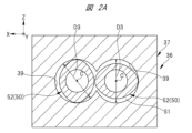
- 2 is a cross-sectional view taken along line AA in FIG. 1.
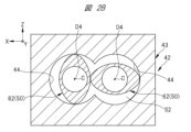
- 2 is a cross-sectional view taken along line BB in FIG. 1.
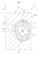
- FIG. 2 is a cross-sectional view showing a schematic diagram of a crest diameter and a root diameter of a screw.
- FIG. 13 is a perspective view showing a progressive flight in the upstream zone.
- FIG. 13 is a side view of the progressive flight in the upstream zone.
- FIG. 2 is a perspective view showing progressive kneading in the upstream zone.
- FIG. 13 is a side view of the progressive kneading in the upstream zone.
- FIG. 2 is a cross-sectional view showing a part of a cross section taken along line AA in FIG. 1.
- 2 is a cross-sectional view showing a part of a cross section taken along line BB in FIG. 1.
- 2 is a cross-sectional view showing a part of a cross section taken along line CC in FIG. 1.
- 2 is a cross-sectional view showing a part of a cross section taken along line DD in FIG. 1.
- FIG. 6 is a partial cross-sectional view showing the structure of an extruder according to a second embodiment.
- FIG. 11 is a partial cross-sectional view showing the structure of an extruder according to a third embodiment.
- FIG. 11 is a cross-sectional view showing a portion of an extruder according to a fourth embodiment where a reverse feed flight is provided.
- FIG. 11 is a cross-sectional view showing a portion of an extruder according to a fourth embodiment where reverse kneading is provided.
- FIG. 13 is a perspective view showing a reverse feed flight according to a fourth embodiment.
- FIG. 13 is a side view of the reverse feed flight of the fourth embodiment.
- FIG. 13 is a perspective view showing reverse kneading in the fourth embodiment.
- FIG. 13 is a side view of the reverse kneading of the fourth embodiment.
- FIG. 13 is a cross-sectional view showing a forward flight of the fifth embodiment.
- FIG. 13 is a cross-sectional view showing a forward flight of the sixth embodiment.
- FIG. 13 is a cross-sectional view showing a forward flight of the seventh embodiment.
- 13 is a partial cross-sectional view showing a structure of an extruder provided with a temperature changing unit according to a modified example.
- the conveying direction of the resin material P which will be described later, may be referred to as the Y direction.
- the Y direction is included in the horizontal direction.
- the arrow Y in the figure indicates the Y direction.
- the base end side of the arrow Y corresponds to the upstream side.
- the tip side of the arrow Y corresponds to the downstream side.
- the vertical direction perpendicular to the conveying direction may be referred to as the Z direction.
- the arrow Z in the figure indicates the Z direction.
- the base end of the arrow Z corresponds to the lower side.
- the tip end of the arrow Z corresponds to the upper side.
- the left-right direction perpendicular to both the conveying direction and the vertical direction may be referred to as the X direction.
- the X direction is included in the horizontal direction.
- Arrow X in the figure indicates the X direction.
- the base end side of arrow X corresponds to the left side of extruder 10 when viewed from the upstream side to the downstream side in the conveying direction.
- the tip side of arrow X corresponds to the right side of extruder 10.
- the X direction, Y direction, and Z direction are perpendicular to each other.
- the extruder 10 of the first embodiment is used for melt-kneading of resin pellets PR, which is an example of a resin material P.
- the extruder 10 is supported on a base 12 fixed to an installation floor FL.
- the extruder 10 is a twin-screw extruder equipped with two screws 50 (Figs. 2A and 2B).
- the extruder 10 includes a drive unit 20 that rotates the two screws 50 and a kneading unit 30 including the two screws 50.
- the drive unit 20 includes an electric motor 22 and a reducer 24. Specifically, the rotational force generated by the electric motor 22 is transmitted to the reducer 24, and the reduced and high-torque rotational force is transmitted from the reducer 24 to two screws 50 (FIGS. 2A and 2B) of the kneading processing unit 30 via a gear mechanism 26 or the like. As a result, the two screws 50 are rotated in the same direction. However, the two screws 50 can also be rotated in different directions depending on the purpose of the melt-kneading process, etc.
- the kneading section 30 has a hopper 32, a cylinder unit 34, two screws 50 (FIGS. 2A and 2B), and a discharge section 46.
- the cylinder unit 34 is supported by the base 12.
- the cylinder unit 34 is disposed parallel to the installation floor FL.
- the cylinder unit 34 includes a cylinder 36 extending along the Y direction and a cylinder 42 connected to the cylinder 36 and extending along the Y direction.
- a range with a radius of D3 (FIG. 2A) is defined as an upstream zone K1.
- a range with a radius of D4 (FIG. 2B) is defined as a downstream zone K2.
- the cylinder 36 is made up of two blocks 37 lined up in the Y direction.
- Each of the two blocks 37 has a cylindrical upstream conveying path 39 that penetrates in the Y direction.
- the two upstream conveying paths 39 are lined up in the X direction ( Figure 2A).
- the upstream block 37 has a supply port 37A.
- the supply port 37A penetrates from the outside to the upstream conveying path 39.
- the cylinder 42 is, for example, made up of four blocks 43 lined up in the Y direction.
- a cylindrical downstream conveying path 44 penetrating in the Y direction is formed in the four blocks 43.
- Two downstream conveying paths 44 are lined up in the X direction ( Figure 2B).
- a discharge section 46 from which the molten resin MR is discharged is provided downstream of the cylinder 42 in the Y direction.
- the radius of the cylinder 36 (upstream conveying path 39) is D3 (mm).
- the radius of the cylinder 42 (downstream conveying path 44) is D4 (mm).
- the size of radius D3 is smaller than the size of radius D4.
- the cross-sectional area S1 of the upstream conveying path 39 is smaller than the cross-sectional area S2 of the downstream conveying path 44.
- a step 45 ( Figure 1) is formed between block 37 and block 43.
- the two upstream conveying paths 39 partially overlap each other at their opposing portions in the X direction, and communicate with each other at the overlapping portions.
- the two downstream conveying paths 44 partially overlap each other at their opposing portions in the X direction, and communicate with each other at the overlapping portions.
- two screws 50 are disposed inside the cylinders 36 and 42.
- the two screws 50 are, for example, double-thread screws.
- the two screws 50 have a function of conveying while kneading the resin material P (resin pellets PR, molten resin MR) present in the upstream conveying path 39 and the downstream conveying path 44 from the upstream side to the downstream side in the Y direction.
- the positions of the rotation centers of the two screws 50 coincide with the positions of the centers C of the two upstream conveying paths 39 and the centers C of the two downstream conveying paths 44. For this reason, in the following explanation, the position of the central axis of the screw 50 will also be referred to as center C.
- the two screws 50 do not interfere with each other and can each rotate smoothly.
- the screw 50 includes an upstream screw 52 located in the cylinder 36 and a downstream screw 62 located in the cylinder 42.
- the upstream screw 52 and the downstream screw 62 have the same central axis and rotate together.
- the range A1 indicated by the arrow in FIG. 1 means the installation range of the upstream screw 52 in the Y direction.
- the range A2 indicated by the arrow means the installation range of the downstream screw 62 in the Y direction.
- the downstream end of the upstream screw 52 is located (penetrates) in the cylinder 42, but it is preferable that the boundary position between the upstream screw 52 and the downstream screw 62 is at the boundary position between the upstream zone K1 and the downstream zone K2.
- FIG. 3 shows an X-Z cross section of the screw SQ.
- the axial direction of the screw SQ is along the Y direction.
- the position of the central axis of the screw SQ is represented by center C.
- the "peak portion” of the screw SQ is defined as the peak portion M.
- the “peak diameter” of the screw SQ is defined as the peak diameter D (mm).
- the "valley portion” of the screw SQ is defined as the valley portion V.
- the “valley diameter” of the screw SQ is defined as the valley diameter d (mm).
- the imaginary line DE is an imaginary circle whose diameter is the effective diameter of the screw SR.
- the “peak portion M” is the portion located radially outward of the screw SQ with respect to the imaginary line DE when the screw SQ is viewed in a cross section perpendicular to the axial direction (X-Z cross section).
- the “valley portion V” is the portion located radially inward of the screw SQ with respect to the imaginary line DE.
- Crown diameter D is the distance D between center C and position PA when the distance from center C to the outer peripheral surface of ridge M is maximum when viewed in the X-Z cross section.
- the "valley diameter d" is the distance d between the center C and the position PB on the outer peripheral surface of the valley V when the distance from the center C to the outer peripheral surface is the smallest when viewed in the X-Z cross section.
- the upstream screw 52 includes, as an example, a shaft 52A, a progressive flight 54 as an example of a conveying section, a progressive kneading section 56 as an example of a kneading section, and a progressive flight 58 as an example of a conveying section.
- the progressive flight 54 and the progressive flight 58 transport the resin material P downstream in the Y direction as they rotate.
- the length of the progressive flight 54 in the Y direction is longer than the length of the progressive flight 58 in the Y direction.
- the progressive flight 54 and the progressive flight 58 have the same configuration except for the length in the Y direction. For this reason, hereinafter, the progressive flight 54 will be described, and a description of the progressive flight 58 will be omitted.
- the rotation direction of the upstream screw 52 is the clockwise direction indicated by the arrow CW.
- the forward flight 54 is formed in a right-handed screw shape with helical peaks 54A and valleys 54B so that the resin material P (FIG. 1) moves in the Y direction (forward direction).
- a fixing hole 54C through which the shaft 52A (FIG. 1) is inserted is provided in the rotation center of the forward flight 54.
- the shaft 52A is serrated fitted into the fixing hole 54C to enable large torque transmission.
- the progressive kneader 56 rotates to knead the resin material P.
- the progressive kneader 56 also has a function of conveying the resin material P downstream while kneading it.
- the forward kneading 56 is formed in a shape in which multiple peaks 56A and valleys 56B are arranged in a spiral shape so that the resin material P (Figure 1) is kneaded and transported in the Y direction (forward direction).
- a fixing hole 56C Figure 5A
- the shaft 52A is serrated-fitted to the fixing hole 56C to enable large torque transmission.
- the downstream screw 62 includes a shaft 52A, progressive kneaders 64, 65, and 66 as an example of a kneading section, and progressive flights 72, 73, and 74 as an example of another conveying section.
- the progressive kneaders 64, 65, and 66 and the progressive flights 72, 73, and 74 are alternately arranged along the Y direction.
- the forward kneading 64 is located downstream in the Y direction with respect to the forward flight 58.
- the forward kneading 64, 65, 66 knead the resin material P as they rotate.
- the forward kneading 64, 65, 66 also have the function of conveying the resin material P downstream while kneading it.
- the forward kneading 64, 65, 66 are members having an external shape similar to that of the forward kneading 56, but have different dimensions from the forward kneading 56.
- the forward kneading 64, 65, 66 are fixed to the shaft 52A, like the forward kneading 56.
- the progressive flights 72, 73, and 74 transport the resin material P downstream in the Y direction as they rotate.
- the progressive flights 72, 73, and 74 have different lengths in the Y direction.
- the progressive flights 72, 73, and 74 are members having an external shape similar to that of the progressive flight 54, but have different dimensions from the progressive flight 54.
- the progressive flights 72, 73, and 74 are fixed to the shaft 52A, similar to the progressive flight 54.
- the progressive flight 54 has a crest 54A and a valley 54B.
- the crest 54A refers to a portion located radially outward of an imaginary circle having a diameter equal to the effective diameter of the upstream screw 52.
- the valley 54B refers to a portion located radially inward of an imaginary circle having a diameter equal to the effective diameter of the upstream screw 52.
- the progressive flight 54 is shown by a solid line, and a progressive flight 72, which will be described later, is shown by a two-dot chain line.
- the ridge diameter D1 (mm) of the progressive flight 54 is the distance between the center C and position P1 on the outer peripheral surface of the ridge portion 54A when viewed in the X-Z cross section, where P1 is the position on the outer peripheral surface when the distance from the center C to the outer peripheral surface of the ridge portion 54A is at its maximum.
- the valley diameter d1 (mm) of the progressive flight 54 is the distance between the center C and position P2 on the outer peripheral surface of the valley portion 54B when viewed in the X-Z cross section, where P2 is the position on the outer peripheral surface where the distance from the center C to the outer peripheral surface of the valley portion 54B is the smallest.
- the radius of the cylinder 36 is D3 (mm).
- the illustration of the ratios R1 and R3 is omitted.
- the forward flight 72 has a crest 72A and a valley 72B.
- the crest 72A refers to a portion located radially outward of an imaginary circle whose diameter is the effective diameter of the downstream screw 62.
- the valley 72B refers to a portion located radially inward of an imaginary circle whose diameter is the effective diameter of the downstream screw 62.
- the ridge diameter D2 (mm) of the progressive flight 72 is the distance between the center C and position P3, where P3 is the position on the outer peripheral surface where the distance from the center C to the outer peripheral surface of the ridge portion 72A is at its maximum.
- the valley diameter d2 (mm) of the forward flight 54 is the distance between the center C and position P4 on the outer peripheral surface of the valley portion 72B when viewed in the X-Z cross section, where P4 is the position on the outer peripheral surface when the distance from the center C to the outer peripheral surface of the valley portion 72B is the smallest.
- the radius of the cylinder 42 is D4 (mm).
- the illustration of the ratios R2 and R4 is omitted.
- ratio R1 is smaller than ratio R2
- ratio R3 is smaller than ratio R4.
- the forward kneading 56 has a peak 56A and a valley 56B.
- the peak 56A means a portion located radially outward of a virtual circle having a diameter equal to the effective diameter of the upstream screw 52.
- the valley 56B means a portion located radially inward of a virtual circle having a diameter equal to the effective diameter of the upstream screw 52.
- the crest diameter D5 (mm) of the progressive kneading 56 is the distance between the center C and position P5, where P5 is the position on the outer peripheral surface when the distance from the center C to the outer peripheral surface of the crest 56A is at its maximum.
- the valley diameter d5 (mm) of the progressive kneading 56 is the distance between the center C and position P6 on the outer peripheral surface when the distance from the center C to the outer peripheral surface of the valley portion 56B is the smallest when viewed in the X-Z cross section.
- the forward kneading 64 has a peak 64A and a valley 64B.
- the peak 64A refers to a portion located radially outward of an imaginary circle whose diameter is the effective diameter of the downstream screw 62.
- the valley 64B refers to a portion located radially inward of an imaginary circle whose diameter is the effective diameter of the downstream screw 62.
- the crest diameter D6 (mm) of the progressive kneading 64 is the distance between the center C and position P7, where P7 is the position on the outer peripheral surface when the distance from the center C to the outer peripheral surface of the crest 64A is at its maximum.
- the valley diameter d6 (mm) of the progressive kneading 64 is the distance between the center C and position P8 when viewed in the X-Z cross section, where P8 is the position on the outer peripheral surface when the distance from the center C to the outer peripheral surface of the valley portion 64B is the smallest.
- the illustration of the ratios R7 and R8 is omitted.
- the ratio R5 is smaller than the ratio R7
- the ratio R6 is smaller than the ratio R8.
- each value is set so that D1/d1 is less than 1.5. In other words, each value is set so that D2/d2 is 1.5 or greater.
- the filling rate of the resin material P in the upstream zone K1 increases and the conveying capacity of the resin material P also increases. This prevents the resin pressure and volatile gases generated during kneading in the downstream zone K2 from backflowing into the upstream zone K1, allowing the extruder 10 to operate stably and continuously.
- the length of the upstream zone K1 in the Y direction is L1 (mm) ( Figure 1). If the length L1 is too short, there is a possibility that the pressure boosting capacity will be insufficient.
- the spatial volume is set within a preferred range, taking into account not only the radius of the screw 50 but also the radius of the cylinder unit 34. This further prevents the resin pressure and volatile gases generated during kneading in the downstream zone K2 from backflowing to the upstream zone K1.
- the downstream screw 62 includes progressive kneading flights 64, 65, and 66. This allows the resin material P to be heated by heat generated by the shearing action that accompanies the rotation of the screw 50, compared to a configuration in which the downstream screw 62 only has progressive flights 72, 73, and 74.
- the downstream screw 62 includes progressive flights 72, 73, and 74. This allows the downstream screw 62 to have a higher conveying capacity for the resin material P than a configuration in which the downstream screw 62 only has progressive kneadings 64, 65, and 66.
- the upstream screw 52 includes a progressive kneading 56. This allows the resin material P to be heated by heat generated by the shearing action that accompanies the rotation of the screw 50, compared to a configuration in which the upstream screw 52 only has a progressive flight 54.
- Figure 10 shows a portion of the extruder 80 in the Y direction.
- the extruder 80 differs from the extruder 10 ( Figure 1) in that an adapter 82 is added to the cylinder 36.
- the configuration other than the adapter 82 is the same, except for the length of the screw 50 in the Y direction.
- the adapter 82 is provided at the downstream end of the cylinder 36 in the conveying direction (Y direction) of the resin material P.
- the adapter 82 is an example of an enlarged diameter section.
- the adapter 82 has a hole 83 that constitutes part of the conveying path of the resin material P.
- the shape of the X-Z cross section of the hole 83 is circular.
- the radius of the upstream end of the hole 83 in the Y direction is D3.
- the radius of the downstream end of the hole 83 in the Y direction is D4.
- the radius increases continuously from D3 to D4 toward the cylinder 42. In other words, in the hole 83, the inner diameter increases continuously toward the cylinder 42.
- the radius of the adapter 82 increases continuously from D3 to D4. In other words, no step is formed. This prevents a portion of the resin material P being transported in the Y direction from remaining in the step portion, allowing the resin material P to be transported smoothly from the cylinder 36 to the cylinder 42.
- FIG. 11 shows an extruder 90.
- Extruder 90 differs from extruder 10 (FIG. 1) in that progressive flights 92, 94 are added to the downstream screw 62, a flow path 93 is provided in the first block 43 (cylinder 42), and a pressure adjustment unit 96 is provided instead of the discharge unit 46 (FIG. 1).
- the flow path 93 penetrates the block 43 in the Z direction and is connected to the downstream conveying path 44.
- Water W is supplied to the flow path 93 as an example of a liquid material.
- liquid resin or the like may be used instead of water W.
- the pressure adjustment unit 96 is provided downstream of the cylinder 42.
- the pressure adjustment unit 96 has a hole 97 with a radius smaller than the radius D3 ( Figure 6).
- the hole 97 extends along the Y direction.
- the pressure adjustment unit 96 can adjust the pressure inside the cylinder 42 by changing the size of the radius (inner diameter) of the hole 97.
- the resin material P is supplied in the upstream zone K1, and the water W is supplied in the downstream zone K2.
- the upstream zone K1 the relationship between the peak diameter and valley diameter described above is satisfied, thereby enhancing the pressurization capacity.
- This improves the sealing performance in the upstream zone K1 against the resin material P, water W, and gas generated by kneading present in the downstream zone K2, making it possible to suppress backflow from the downstream zone K2 to the upstream zone K1.
- the size of the extruder 90 in the conveying direction (Y direction) can be reduced.
- FIG. 4 shows a configuration in which a reverse flight 102 and a reverse kneading 106 are added to the extruder 10 as a fourth embodiment of the present disclosure.
- the reverse flight 102 is shown in Figs. 13A and 13B.
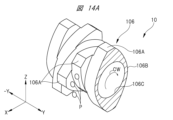
- the reverse kneading 106 is shown in Figs. 14A and 14B. Note that for configurations that are the same as or similar to the configuration of the extruder 10 of the first embodiment, reference is made to Fig. 1, and description of the figure numbers is omitted, and the same reference numerals are used to omit the description.
- the reverse flight 102 is formed in a screw shape with spiral crests 102A and valleys 102B so that when the rotation direction is the direction shown by the arrow CW ( Figure 13A), the resin material P moves in the direction of the arrow -Y (reverse direction).
- the reverse flight 102 is an example of a reverse conveying section.
- a fixing hole 102C ( Figure 13A) through which the shaft 52A is inserted is provided in the rotation center of the reverse flight 102.
- the shaft 52A is serrated fitted into the fixing hole 102C to enable large torque transmission.
- the reverse feed flight 102 is provided, as an example, at the upstream end of the upstream screw 52 in the Y direction. Also, a discharge outlet 103 is provided at the upstream end of the upstream zone K1 of the extruder 10.
- the reverse feed flight 102 rotates in conjunction with the rotation of the upstream screw 52, so that the resin material P that is remaining upstream of the supply port 37A can be discharged from the discharge outlet 103.
- the reverse kneading 106 is formed in a shape in which multiple peaks 106A are arranged in a spiral shape so that when the rotation direction is the direction indicated by the arrow CW ( Figure 14A), the resin material P is kneaded and transported in the direction of the arrow -Y (reverse direction).
- the reverse kneading 106 is an example of a kneading section and an example of a reverse transport section.
- the reverse kneading 106 also has multiple valleys 106B.
- a fixed hole 106C ( Figure 14A) through which the shaft 52A is inserted is provided at the rotation center of the reverse kneading 106.
- the shaft 52A is also serrated fitted into the fixed hole 106C to enable large torque transmission.
- the reverse kneading 106 is provided, as an example, at the downstream end of the downstream screw 62 in the Y direction. Also, a discharge outlet 107 is provided in a part of the downstream zone K2 of the extruder 10.
- the reverse kneading 106 is rotated in conjunction with the rotation of the downstream screw 62, so that the resin material P that is retained upstream of the discharge section 46 (FIG. 1) of the downstream zone K2 can be discharged from the discharge outlet 107.
- an extruder 10 provided with a reverse flight 102 and a reverse kneading 106 may be used.
- FIG. 15A illustrates a forward flight 112 as a fifth embodiment of the present disclosure. Note that components that are the same as or similar to the components of the extruder 10 of the first embodiment are denoted by the same reference numerals and will not be described.
- the forward flight 112 is an example of a conveying section.
- the forward flight 112 constitutes a single-thread type screw 111 and has a crest 112A and a valley 112B.
- the valley 112B having a valley diameter d7 and the crest 112A having a crest diameter D7 are aligned in the radial direction of the screw 111.
- a fixing hole 112C through which the shaft 52A ( Figure 1) is inserted is provided in the rotation center of the forward flight 112.
- the peak portion 112A refers to a portion located radially outward of an imaginary circle whose diameter is the effective diameter of the screw 111.
- the valley portion 112B refers to a portion located radially inward of an imaginary circle whose diameter is the effective diameter of the screw 111.
- the crest diameter D7 (mm) of the forward flight 112 is the distance between the center C and position P9, where P9 is the position on the outer peripheral surface when the distance from the center C to the outer peripheral surface of the crest 112A is at its maximum.
- the valley diameter d7 (mm) of the forward flight 112 is the distance between the center C and position P10 on the outer peripheral surface of the valley portion 112B when viewed in the X-Z cross section, where P10 is the position on the outer peripheral surface when the distance from the center C to the outer peripheral surface of the valley portion 112B is the smallest.
- the ratio R9 is not shown in the figure.
- FIG. 15B shows a forward flight 114 as a sixth embodiment of the present disclosure. Note that the same or similar components as those of the extruder 10 of the first embodiment are denoted by the same reference numerals and will not be described.
- the forward flight 114 is an example of a conveying section.
- the forward flight 114 constitutes a single-thread type screw 113 and has a crest 114A and a valley 114B.
- a fixing hole 114C through which the shaft 52A ( Figure 1) is inserted is provided at the rotation center of the forward flight 114.
- the peak portion 114A refers to a portion located radially outward of an imaginary circle whose diameter is the effective diameter of the screw 113.
- the valley portion 114B refers to a portion located radially inward of an imaginary circle whose diameter is the effective diameter of the screw 113.
- the valley portion 114B is provided in a circular ring shape when viewed from the axial direction (Y direction) of the screw 113.
- the peak portion 114A is a protruding portion that protrudes radially outward from a portion of the circumference of the valley portion 114B.
- the crest diameter D8 (mm) of the forward flight 114 is the distance between the center C and position P11 on the outer peripheral surface of the crest 114A when viewed in the X-Z cross section, where P11 is the position on the outer peripheral surface when the distance from the center C to the outer peripheral surface of the crest 114A is at its maximum.
- the valley diameter d8 (mm) of the forward flight 114 is the distance between the center C and position P12 on the outer peripheral surface of the valley portion 114B when viewed in the X-Z cross section, where P12 is the position on the outer peripheral surface when the distance from the center C to the outer peripheral surface of the valley portion 114B is the smallest.
- the ratio R10 is not shown.
- FIG. 15C illustrates a forward flight 116 as a seventh embodiment of the present disclosure. Note that the same or similar components as those of the extruder 10 of the first embodiment are denoted by the same reference numerals and will not be described.
- the forward flight 116 is an example of a conveying section.
- the forward flight 116 constitutes a three-thread type screw 115 and has three peaks 116A and three valleys 116B.
- the three peaks 116A and the three valleys 116B are aligned in the circumferential direction of the screw 115.
- a plurality of peaks 116A and valleys 116B are provided in the circumferential direction of the screw 115.
- a fixing hole 116C through which the shaft 52A ( Figure 1) is inserted is provided in the rotation center of the forward flight 116.
- the peak portion 116A refers to a portion located radially outward of an imaginary circle whose diameter is the effective diameter of the screw 115.
- the valley portion 116B refers to a portion located radially inward of an imaginary circle whose diameter is the effective diameter of the screw 115.
- the crest diameter D9 (mm) of the forward flight 116 is the distance between the center C and position P13 on the outer peripheral surface of the crest 116A when viewed in the X-Z cross section, where P13 is the position on the outer peripheral surface when the distance from the center C to the outer peripheral surface of the crest 116A is at its maximum.
- the valley diameter d9 (mm) of the forward flight 116 is the distance between the center C and position P14 on the outer peripheral surface of the valley portion 116B when viewed in the X-Z cross section, where P14 is the position on the outer peripheral surface when the distance from the center C to the outer peripheral surface of the valley portion 116B is the smallest.
- the extruder 10 may be configured such that only the relationship D1/d1 ⁇ D2/d2 holds, and the relationship D3/d1 ⁇ D4/d2 does not hold.
- a temperature change unit 122 may be provided in each of block 37 (cylinder 36) and block 43 (cylinder 42).
- the temperature change unit 122 includes at least one of a cooling unit that cools the resin material P and a heating unit that heats the resin material P.
- the number of cooling units and the number of heating units may each be either single or multiple.
- a cooling unit a pipe through which a liquid such as water flows may be provided, and cooling may be performed by exchanging heat in the pipe.
- a heating unit a heater may be provided, and heating may be performed by heat generated by passing electricity through the heater.
- the temperature change unit 122 may be provided only in the cylinder 36.
- the temperature change unit 122 may be provided only in the cylinder 42.
- only the forward flight 54 may be provided in the upstream zone K1.
- Only the forward flight 72 may be provided in the downstream zone K2.
- Only the forward kneading 64 may be provided in the downstream zone K2.
- Only the forward flight 54 may be provided in the upstream zone K1, and only the forward flight 72 may be provided in the downstream zone K2.
- Only the forward flight 54 may be provided in the upstream zone K1, and only the forward kneading 64 may be provided in the downstream zone K2.
- the forward flight 54 may be provided in the upstream zone K1, and the forward kneading 64 and the forward flight 72 may be provided in the downstream zone K2.Only the forward flight 54 and the forward kneading 56 may be provided in the upstream zone K1.
- An adapter 82 may be added to the extruder 90.
- each component in each of the above embodiments are arbitrary as long as they can achieve the present disclosure, and are not limited to the above embodiments and modified examples.
Landscapes
- Engineering & Computer Science (AREA)
- Mechanical Engineering (AREA)
- Physics & Mathematics (AREA)
- Thermal Sciences (AREA)
- Extrusion Moulding Of Plastics Or The Like (AREA)
- Processing And Handling Of Plastics And Other Materials For Molding In General (AREA)
Priority Applications (4)
| Application Number | Priority Date | Filing Date | Title |
|---|---|---|---|
| CN202380053665.6A CN119546442A (zh) | 2023-05-16 | 2023-05-16 | 挤出机 |
| JP2025520296A JP7851492B2 (ja) | 2023-05-16 | 2023-05-16 | 押出機 |
| EP23937466.3A EP4691732A1 (en) | 2023-05-16 | 2023-05-16 | Extruder |
| PCT/JP2023/018235 WO2024236724A1 (ja) | 2023-05-16 | 2023-05-16 | 押出機 |
Applications Claiming Priority (1)
| Application Number | Priority Date | Filing Date | Title |
|---|---|---|---|
| PCT/JP2023/018235 WO2024236724A1 (ja) | 2023-05-16 | 2023-05-16 | 押出機 |
Publications (1)
| Publication Number | Publication Date |
|---|---|
| WO2024236724A1 true WO2024236724A1 (ja) | 2024-11-21 |
Family
ID=93519484
Family Applications (1)
| Application Number | Title | Priority Date | Filing Date |
|---|---|---|---|
| PCT/JP2023/018235 Ceased WO2024236724A1 (ja) | 2023-05-16 | 2023-05-16 | 押出機 |
Country Status (4)
| Country | Link |
|---|---|
| EP (1) | EP4691732A1 (https=) |
| JP (1) | JP7851492B2 (https=) |
| CN (1) | CN119546442A (https=) |
| WO (1) | WO2024236724A1 (https=) |
Citations (9)
| Publication number | Priority date | Publication date | Assignee | Title |
|---|---|---|---|---|
| JPS4832156A (https=) * | 1971-08-30 | 1973-04-27 | ||
| JPS5747633A (en) * | 1980-07-16 | 1982-03-18 | Berstorff Gmbh Masch Hermann | Biaxial screw type degassing extruding machine for degassing thermoplastic material or similar material |
| JPS5939536A (ja) * | 1982-08-31 | 1984-03-03 | Modern Mach Kk | 溶融樹脂の押出し機 |
| JPS5964340A (ja) * | 1982-08-26 | 1984-04-12 | ヘルマン・ベルシユトルフ・マシイネンバウ・ゲゼルシヤフト・ミト・ベシユレンクテル・ハフツング | ベント式押出し機 |
| JPS6398412A (ja) * | 1986-10-15 | 1988-04-28 | Mazda Motor Corp | 合成樹脂シ−ト幅可変押出装置 |
| JPH11240059A (ja) * | 1995-06-19 | 1999-09-07 | Japan Steel Works Ltd:The | 混練押出機 |
| JP2009184303A (ja) | 2008-02-08 | 2009-08-20 | Japan Steel Works Ltd:The | 二軸スクリュ押出機における脱揮成分の分離方法及び装置 |
| KR20090114643A (ko) * | 2008-04-30 | 2009-11-04 | (주)이엔에스 | 플라스틱 압출성형기의 배기식 스크류 |
| WO2017179584A1 (ja) * | 2016-04-15 | 2017-10-19 | 住友化学株式会社 | 樹脂組成物の製造方法および二軸混練押出機 |
-
2023
- 2023-05-16 WO PCT/JP2023/018235 patent/WO2024236724A1/ja not_active Ceased
- 2023-05-16 EP EP23937466.3A patent/EP4691732A1/en active Pending
- 2023-05-16 CN CN202380053665.6A patent/CN119546442A/zh active Pending
- 2023-05-16 JP JP2025520296A patent/JP7851492B2/ja active Active
Patent Citations (9)
| Publication number | Priority date | Publication date | Assignee | Title |
|---|---|---|---|---|
| JPS4832156A (https=) * | 1971-08-30 | 1973-04-27 | ||
| JPS5747633A (en) * | 1980-07-16 | 1982-03-18 | Berstorff Gmbh Masch Hermann | Biaxial screw type degassing extruding machine for degassing thermoplastic material or similar material |
| JPS5964340A (ja) * | 1982-08-26 | 1984-04-12 | ヘルマン・ベルシユトルフ・マシイネンバウ・ゲゼルシヤフト・ミト・ベシユレンクテル・ハフツング | ベント式押出し機 |
| JPS5939536A (ja) * | 1982-08-31 | 1984-03-03 | Modern Mach Kk | 溶融樹脂の押出し機 |
| JPS6398412A (ja) * | 1986-10-15 | 1988-04-28 | Mazda Motor Corp | 合成樹脂シ−ト幅可変押出装置 |
| JPH11240059A (ja) * | 1995-06-19 | 1999-09-07 | Japan Steel Works Ltd:The | 混練押出機 |
| JP2009184303A (ja) | 2008-02-08 | 2009-08-20 | Japan Steel Works Ltd:The | 二軸スクリュ押出機における脱揮成分の分離方法及び装置 |
| KR20090114643A (ko) * | 2008-04-30 | 2009-11-04 | (주)이엔에스 | 플라스틱 압출성형기의 배기식 스크류 |
| WO2017179584A1 (ja) * | 2016-04-15 | 2017-10-19 | 住友化学株式会社 | 樹脂組成物の製造方法および二軸混練押出機 |
Non-Patent Citations (1)
| Title |
|---|
| See also references of EP4691732A1 |
Also Published As
| Publication number | Publication date |
|---|---|
| EP4691732A1 (en) | 2026-02-11 |
| CN119546442A (zh) | 2025-02-28 |
| JPWO2024236724A1 (https=) | 2024-11-21 |
| JP7851492B2 (ja) | 2026-04-24 |
Similar Documents
| Publication | Publication Date | Title |
|---|---|---|
| US6170975B1 (en) | Multi-shaft extruder kneading discs, kneading disc blocks and extruder | |
| JP2905418B2 (ja) | 混練機 | |
| US5728337A (en) | Twin screw extruder and an extruding method using the same | |
| KR101452653B1 (ko) | 연속 혼련기 및 혼련 방법 | |
| US8087815B2 (en) | Kneader | |
| JP6446310B2 (ja) | 押出機用スクリュ、押出機および押出方法 | |
| US20050089595A1 (en) | Extruder for the continuous handling and/or processing of free-flowing materials | |
| US11273420B2 (en) | Extruder screw, extrusion device having an extruder screw and method for plasticizing a plastic | |
| TW201946754A (zh) | 導電性複合材料的製造方法 | |
| CN101547781B (zh) | 多轴挤出机 | |
| TW201615277A (zh) | 擠壓機用螺旋桿和擠壓機及擠壓方法 | |
| KR20170078751A (ko) | 압출기용 스크루, 스크루 엘리먼트, 압출기 및 압출 방법 | |
| US20050084559A1 (en) | Extruder | |
| JP4610564B2 (ja) | 歯車ポンプ | |
| WO2024236724A1 (ja) | 押出機 | |
| WO2025246178A1 (zh) | 异向差速螺杆捏合装置、连续捏合机、物料制作系统 | |
| JP2007508965A5 (https=) | ||
| EP1148987B1 (en) | Multi-shaft extruder screw bushing and extruder | |
| JP4619123B2 (ja) | 押出成形装置/歯車ポンプの組合せ | |
| JPS63278537A (ja) | 混合機及び押出し機 | |
| JP7431297B1 (ja) | スクリュ機械及び混練方法 | |
| JP2023097743A (ja) | 溶融混練押出装置の運転の際に必要なエネルギーを低減可能とする方法 | |
| JP2009148936A (ja) | 混練スクリュ及び押出機 | |
| TWI797886B (zh) | 螺旋機 | |
| JPH07148821A (ja) | スクリュータイプの押し出し機用のスクリュー要素及び当該スクリュー要素を有するスクリューシャフト配置 |
Legal Events
| Date | Code | Title | Description |
|---|---|---|---|
| WWE | Wipo information: entry into national phase |
Ref document number: 2025520296 Country of ref document: JP |
|
| 121 | Ep: the epo has been informed by wipo that ep was designated in this application |
Ref document number: 23937466 Country of ref document: EP Kind code of ref document: A1 |
|
| WWE | Wipo information: entry into national phase |
Ref document number: 202380053665.6 Country of ref document: CN |
|
| WWP | Wipo information: published in national office |
Ref document number: 202380053665.6 Country of ref document: CN |
|
| WWE | Wipo information: entry into national phase |
Ref document number: 202517032370 Country of ref document: IN |
|
| WWP | Wipo information: published in national office |
Ref document number: 202517032370 Country of ref document: IN |
|
| WWE | Wipo information: entry into national phase |
Ref document number: 2023937466 Country of ref document: EP |
|
| ENP | Entry into the national phase |
Ref document number: 2023937466 Country of ref document: EP Effective date: 20251106 |
|
| ENP | Entry into the national phase |
Ref document number: 2023937466 Country of ref document: EP Effective date: 20251106 |
|
| ENP | Entry into the national phase |
Ref document number: 2023937466 Country of ref document: EP Effective date: 20251106 |
|
| ENP | Entry into the national phase |
Ref document number: 2023937466 Country of ref document: EP Effective date: 20251106 |
|
| ENP | Entry into the national phase |
Ref document number: 2023937466 Country of ref document: EP Effective date: 20251106 |
|
| NENP | Non-entry into the national phase |
Ref country code: DE |
|
| ENP | Entry into the national phase |
Ref document number: 2023937466 Country of ref document: EP Effective date: 20251106 |
|
| ENP | Entry into the national phase |
Ref document number: 2023937466 Country of ref document: EP Effective date: 20251106 |
|
| ENP | Entry into the national phase |
Ref document number: 2023937466 Country of ref document: EP Effective date: 20251106 |
|
| WWP | Wipo information: published in national office |
Ref document number: 2023937466 Country of ref document: EP |