WO2024236705A1 - 携帯端末および通報解除方法 - Google Patents
携帯端末および通報解除方法 Download PDFInfo
- Publication number
- WO2024236705A1 WO2024236705A1 PCT/JP2023/018158 JP2023018158W WO2024236705A1 WO 2024236705 A1 WO2024236705 A1 WO 2024236705A1 JP 2023018158 W JP2023018158 W JP 2023018158W WO 2024236705 A1 WO2024236705 A1 WO 2024236705A1
- Authority
- WO
- WIPO (PCT)
- Prior art keywords
- report
- mobile terminal
- automatic
- notification
- user
- Prior art date
- Legal status (The legal status is an assumption and is not a legal conclusion. Google has not performed a legal analysis and makes no representation as to the accuracy of the status listed.)
- Ceased
Links
Images







Classifications
-
- G—PHYSICS
- G08—SIGNALLING
- G08B—SIGNALLING SYSTEMS, e.g. PERSONAL CALLING SYSTEMS; ORDER TELEGRAPHS; ALARM SYSTEMS
- G08B25/00—Alarm systems in which the location of the alarm condition is signalled to a central station, e.g. fire or police telegraphic systems
- G08B25/01—Alarm systems in which the location of the alarm condition is signalled to a central station, e.g. fire or police telegraphic systems characterised by the transmission medium
- G08B25/04—Alarm systems in which the location of the alarm condition is signalled to a central station, e.g. fire or police telegraphic systems characterised by the transmission medium using a single signalling line, e.g. in a closed loop
-
- G—PHYSICS
- G08—SIGNALLING
- G08B—SIGNALLING SYSTEMS, e.g. PERSONAL CALLING SYSTEMS; ORDER TELEGRAPHS; ALARM SYSTEMS
- G08B25/00—Alarm systems in which the location of the alarm condition is signalled to a central station, e.g. fire or police telegraphic systems
- G08B25/01—Alarm systems in which the location of the alarm condition is signalled to a central station, e.g. fire or police telegraphic systems characterised by the transmission medium
- G08B25/08—Alarm systems in which the location of the alarm condition is signalled to a central station, e.g. fire or police telegraphic systems characterised by the transmission medium using communication transmission lines
Definitions
- This disclosure relates to technologies for mobile terminals, etc.
- Some mobile devices such as smartphones and smartwatches have a function (sometimes referred to as an automatic reporting function) that automatically reports an emergency (in other words, when an abnormality occurs, a problem occurs, etc.) to the user who owns the mobile device.
- an automatic reporting function For example, recent smartphones, based on sensing and judging acceleration in response to shocks, etc., can determine and detect a state in which the user, for example, has fallen and is unable to stand, as an emergency/abnormal/problem.
- the smartphone then automatically executes and sends a report (in other words, an automatic report, SOS, distress signal, etc.) to a specified reporting destination such as the police or an ambulance.
- a report in other words, an automatic report, SOS, distress signal, etc.
- Such automatic reporting functions of mobile devices make it easier to respond to rescue efforts immediately in the event of an emergency, and in some cases can save the user's life.
- Patent Document 1 An example of the prior art is JP 2022-37048 A (Patent Document 1).
- Patent Document 1 describes that a mobile device determines that a user has fallen based on an impact, a first motion characteristic of the user at a time before the impact, and a second motion characteristic of the user at a time after the impact, and accordingly generates a notification indicating that the user has fallen.
- the automatic reporting function of the mobile device may sometimes generate false reports even when there is nothing abnormal with the user. For example, when the user is engaged in an activity such as skiing, the user's smartphone may determine an abnormal state based on impact sensing, etc., and the automatic reporting may be generated as a false report even when there is actually no abnormality or problem.
- the automatic reporting function of the mobile device causes a false report, the user may be inconvenienced.
- the systems to which the police, ambulances, etc. are contacted may also be inconvenienced by the need for resources to respond to false reports.
- Patent Document 1 does not describe how to handle the process after an automatic report is made, or how to handle cases where a report is incorrect.
- the purpose of this disclosure is to provide technology related to the automatic reporting function of the mobile terminal that can respond appropriately even in cases of false reports, etc.
- the mobile terminal of the embodiment is a mobile terminal having an automatic reporting function
- the automatic reporting function is a function that automatically issues a first report to a first reporting destination, which is a predetermined reporting destination, when it is determined that the user carrying the mobile terminal is in a first state, which is an emergency, abnormality, or problem state, according to the state of the mobile terminal, and when the automatic reporting is issued, the mobile terminal monitors the state of the mobile terminal during the time following the automatic reporting, and determines whether the first state has been resolved or whether the first report was a false report, and when it is determined that the first state has been resolved or that the first report was a false report, issues a release notification to the first reporting destination to convey that the first report has been released.
- the technology related to the automatic reporting function of the mobile terminal allows for appropriate responses even in the case of erroneous reports. Issues, configurations, effects, etc. other than those described above are shown in the description of the embodiment of the invention.
- FIG. 1 is a diagram showing a configuration of a system including a mobile terminal according to a first embodiment.
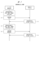
- FIG. 2 is a diagram showing a sequence between a mobile terminal and a notification destination as an overview of the notification cancellation method of the first embodiment.
- FIG. 2 is a diagram showing a configuration example of a smartphone as a mobile terminal according to the first embodiment.
- FIG. 2 is a diagram showing a configuration example of a smart watch as a mobile terminal of embodiment 1.
- FIG. 2 is a diagram showing an example of a software configuration of the mobile terminal of the first embodiment.
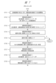
- FIG. 13 is a diagram showing a processing flow (1-1) of the mobile terminal of the first embodiment.
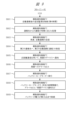
- FIG. 13 is a diagram showing a processing flow (1-2) of the mobile terminal of the first embodiment.
- FIG. 1 is a diagram showing a configuration of a system including a mobile terminal according to a first embodiment.
- FIG. 2 is a diagram showing a sequence between a mobile terminal and a notification destination as an overview of the
- FIG. 13 is a diagram showing a processing flow (1-3) of the mobile terminal of the first embodiment.
- FIG. 13 is a diagram showing a processing flow (1-4) of the mobile terminal of the first embodiment.
- FIG. 4 is a diagram showing an example of a screen display of the mobile terminal according to the first embodiment.
- FIG. 4 is a diagram showing an example of a screen display of the mobile terminal according to the first embodiment.
- FIG. 4 is a diagram showing an example of a screen display of the mobile terminal according to the first embodiment.
- 11A and 11B are diagrams showing the occurrence of automatic reporting and cancellation notification according to the user's state on the time axis in the mobile terminal of the first embodiment.
- FIG. 11 is a diagram showing an example of time interval control for automatic re-notification and the like according to the battery state on a time axis in the mobile terminal of the first embodiment.
- FIG. 4A and 4B are diagrams showing examples of configurations of automatic reporting, release notification, and related information in the mobile terminal of the first embodiment.
- the program, functions, processing units, etc. may be described as the main focus, but the main hardware focus for these is the processor, or a controller, device, computer, system, etc. that is composed of the processor, etc.
- the computer executes processing according to the program read into the memory by the processor, appropriately using resources such as memory and communication interfaces. This realizes the specified functions, processing units, etc.
- the processor is composed of semiconductor devices such as a CPU/MPU or GPU, for example. Processing is not limited to software program processing, but can also be implemented by dedicated circuits. Dedicated circuits that can be used include FPGAs, ASICs, CPLDs, etc.
- the program may be pre-installed as data on the target computer, or may be distributed as data from a program source to the target computer.
- the program source may be a program distribution server on a communication network, or a non-transient computer-readable storage medium, such as a memory card or disk.
- the program may be composed of multiple modules.
- the computer system may be composed of multiple devices.
- the computer system may be composed of a client-server system, a cloud computing system, an IoT system, etc.
- the various data and information are composed of structures such as, for example, tables and lists, but are not limited to these. Expressions such as identification information, identifiers, IDs, names, numbers, etc. are mutually interchangeable.
- the automatic reporting function of the mobile device generates an automatic report based on impact detection. For example, the mobile device will sound a loud alert, vibrate the device, and start a countdown. If the user does not stop the countdown, the mobile device will determine that the user has been involved in a serious accident or other emergency/abnormal/problem situation, and will automatically send an automatic report to an emergency reporting service, etc.
- a human responder when an unnecessary automated call is received by a contact point (such as the police or an ambulance), a human responder must take action, such as checking the user's condition, which consumes limited resources such as time and effort.
- the embodiment has a mechanism for canceling the automatic report after it has been generated, a report cancellation function described below. This provides peace of mind to the user, reduces the time and effort required for the recipient of the report to respond, and reduces the consumption of limited resources.
- Examples of telephone numbers to which automated reporting may be sent are as follows: In Japan, dial 110 for police and 119 for emergency services. In China, dial 110 for police, 120 or 999 for emergency services. In the United States, 911: police/ambulance. In Europe, 112: police and ambulance.
- the mobile terminal according to the first embodiment is a mobile terminal 1 equipped with an automatic notification function F1, as shown in FIG. 1 and the like.
- the notification cancellation method according to the first embodiment is a method executed by the mobile terminal according to the first embodiment.
- the mobile terminal 1 according to the first embodiment has an automatic notification function F1 that automatically issues a first notification, which is an automatic notification 1002, to a first notification destination that is a predetermined notification destination (a notification destination system 2) when it is determined that the user U1 is in a first state that is an emergency, abnormality, or problem state 1001 according to the state of the mobile terminal 1.
- the mobile terminal 1 has a cancellation notification function F2 that monitors the state of the mobile terminal 1 at a time after the automatic notification 1002, determines whether the first state has been resolved or whether the first notification was a false notification, and, if it is determined that the first state has been resolved or that the first notification was a false notification, issues a cancellation notification 1002 to the first notification destination to inform the cancellation of the first notification.
- a cancellation notification function F2 that monitors the state of the mobile terminal 1 at a time after the automatic notification 1002, determines whether the first state has been resolved or whether the first notification was a false notification, and, if it is determined that the first state has been resolved or that the first notification was a false notification, issues a cancellation notification 1002 to the first notification destination to inform the cancellation of the first notification.
- FIG. 1 shows an example of the overall configuration of a system including a mobile terminal 1 according to embodiment 1.
- the system in Fig. 1 (for the sake of explanation, also referred to as a reporting system) is a system in which a mobile terminal 1 of a user U1 and a system 2 to which a report is to be made, such as to the police or an ambulance, are connected via a communication network 9.
- Fig. 2 shows the main sequence between the mobile terminal 1 in Fig. 1 and the system 2 to which a report is to be made, as an overview of the report cancellation method according to embodiment 1.
- User U1 is a person who carries the mobile terminal 1 of the first embodiment and uses functions such as the automatic reporting function F1 and the release notification function F2 in this reporting system.
- the automatic reporting function F1 and the release notification function F2 are implemented in the mobile terminal 1.
- Examples of the mobile terminal 1 include a smartphone 1A and a smart watch 1B, and the details are not limited.
- User U1 may have both the smartphone 1A and the smart watch 1B.
- the smartphone 1A and the smart watch 1B may communicate with each other.
- This state 1001 is a state that is the target of an automatic report 1002.
- the mobile terminal 1 uses the automatic reporting function F1 to determine and detect such an abnormal state 1001 (first state) of the user U1 (step S1 in FIG. 2). Then, the mobile terminal 1 uses the automatic reporting function F1 to send an automatic report 1002 to the system 2, which is the specified reporting destination (step S2 in FIG. 2).
- System 2 which is the destination for calls to the police, ambulances, etc., includes a telephone 2001, a server 2002, a PC 2003, a mobile terminal 2004, etc., and receives the automatic call 1002 (step S2 in FIG. 3).
- User U2 who is the responder U2 is a person who receives the automatic call 1002 and responds by confirming the call or providing rescue.
- responder U2 may carry a mobile terminal 2004 such as a smartphone, and may receive the automatic call 1002 on the mobile terminal 2004.
- Responses by responder U2 include calling out to user U1, checking the status, arranging for rescue, etc., and the details are not limited.
- the mobile terminal 1 of user U1 determines whether the abnormal condition 1001 of user U1 has been resolved or improved after the automatic report 1002 was made, or whether the previous automatic report 1002 was a false report (step S4 in FIG. 2). If the mobile terminal 1 determines that the condition has been resolved or that it was a false report, it sends a cancellation notification 1003 for canceling the previous automatic report 1002 (the condition 1001 associated with it) to the system 2 that is the same destination as the previous automatic report 1002 (step S5 in FIG. 2).
- the system 2 to which the notification was sent receives the cancellation notification 1003, and responder U2 receives the cancellation notification 1003 and takes action such as canceling the automatic notification 1002 (step S6 in FIG. 2).
- the automatic report 1002 is, for example, a report by telephone using a mobile network (in other words, voice data communication), but the details are not limited thereto.
- This automatic report 1002 may also be accompanied by data such as text, voice, and images.
- the operator's system 3 is connected to the communication network 9, and includes the operator's server 3001 and PC 3002.
- the operator's system 3 may communicate with the mobile terminal 1 of the user U1 to provide some of the functions, or may communicate with the system 2 of the destination to provide some of the functions, or may be interposed between the mobile terminal 1 of the user U1 and the system 2 of the destination to be notified.
- the operator's server 3001 may perform processes such as detection and determination of the state related to the automatic notification 1002, or may perform processes such as detection and determination of the state related to the release notification 1003.
- FIG. 1 also illustrates the components described below.
- the mobile terminal 1 of user U1 is connected to the mobile terminal 4001 of another user U3, such as a family member or acquaintance, via the communication network 9.
- the mobile terminal 1 of user U1 may be surrounded (within a relatively close distance range) by the mobile terminal 4001 of another user U3, such as a family member or acquaintance, or may be surrounded by the mobile terminal 4001 of an unspecified other user U3.
- Examples of the surrounding devices 4002 include surveillance cameras, facility servers, and wireless base stations.
- step S1 the automatic notification function F1 of the mobile terminal 1 of the user U1 determines and detects an emergency/abnormal/problem state 1001, such as a fall of the user U1, based on sensing using various sensors, etc.
- step S2 the automatic notification function F1 of the mobile terminal 1 transmits an automatic notification 1002 to a predetermined notification destination system 2 to inform the user U1 of the state 1001 and request rescue, etc.
- step S3 the system 2 to which the call is addressed receives the automatic call 1002 and responds to it.
- a responder U2 checks the automatic call 1002, contacts the mobile terminal 1 of the user U1 who sent the call, and checks the status of the user U1.
- the response in step S3 is shown to be immediate in FIG. 2, it is not necessarily immediate.
- step S4 the mobile terminal 1 uses the release notification function F2 to determine and detect whether the emergency/abnormal/problem state 1001 of the user U1 has been resolved/improved or whether it was a false report at the time after the automatic report 1002, based on additional monitoring including additional sensing.
- step S5 if the cancellation notification function F2 of the mobile terminal 1 determines in step S4 that the problem has been resolved or that it was a false report, it sends a cancellation notification 1003 (in other words, an SOS cancellation notification) to the same destination as the destination of the previous automatic report 1002.
- step S6 the destination system 2 receives the cancellation notification 1003, and the responder U2 responds by canceling (canceling the SOS) the previous automatic report 1002 based on the cancellation notification 1003.
- the mobile terminal 1 uses various sensors to sense the movement, impact, etc. of the mobile terminal 1 or the user U1.
- the mobile terminal 1 compares the motion characteristics of the user U1 before the detected impact with the motion characteristics of the user U1 after the detected impact to determine whether the user U1 has fallen or the like. For example, the motion characteristics before the impact show that the user U1 is walking normally with periodic movements, but the motion characteristics after the impact show that the direction of the body has changed and the movement is irregular. From such changes in motion characteristics, the mobile terminal 1 can estimate an event or state such as a fall of the user U1.
- the mobile terminal 1 determines that the user U1 has fallen or the like, that is, if it determines that the user U1 is in an emergency/abnormal/problem state 1001, it generates an automatic report 1002.
- the automatic report 1002 is a report indicating that the user U1 is in an emergency, abnormal, problem, or other state 1001 due to a fall or the like.
- Patent Document 1 As shown in the state transition diagram of FIG. 12, a certain period of time is waited (1206b) before making an SOS report, and a judgment is made. If the technology of Patent Document 1 judges during this waiting period that there is a need to report, it issues an SOS report (1202) and returns to the nominal state (1202). Also, if the technology of Patent Document 1 judges during this waiting period that there is no need to report, it cancels the SOS report (1210) and returns to the nominal state (1202) without issuing an SOS. In the case of the technology of Patent Document 1, any processing that occurs after issuing an SOS report (1202) is not disclosed.
- a release notification function F2 which is a characteristic function in the first embodiment and is a function for issuing the release notification 1003, will be described.
- release notification function F2 of mobile terminal 1 continues to monitor the status of mobile terminal 1 and user U1, such as their movements.
- Release notification function F2 of mobile terminal 1 determines whether user U1's emergency/abnormal/problem state 1001 has been resolved, or whether the previous automatic report 1002 was a false report when user U1 was in a state where there was no problem, etc. For example, when release notification function F2 of mobile terminal 1 detects a movement such as user U1 standing up after falling and starting to walk again, it determines that abnormal state 1001 has been resolved, or that the state was a false report rather than abnormal state 1001 in the first place.
- the release notification function F2 of the mobile terminal 1 generates a release notification 1003 to inform the same report destination as the previous automatic report 1002 that the abnormality or other condition 1002 of the user U1 related to the previous automatic report 1002 has been resolved or that it was a false report, and automatically transmits the release notification 1003.
- the notification release determination process by the release communication function F2 after the automatic notification 1002 is the same as the automatic notification determination process by the automatic notification function F1 (particularly, a comparison and determination of operating characteristics before and after the impact), but in addition, the parameters of the sensors used are increased and additional monitoring processing including additional sensing is performed.
- the parameters of the sensors etc. to be increased include determining the status of the user U1 by voice input/voice recognition.
- the mobile terminal 1 turns on the voice input/voice recognition function including the microphone. In this on state, the mobile terminal 1 may input/recognize the voice of the user U1 to communicate his/her status or the release of the notification, or may pick up the voice around the mobile terminal 1 to determine the status.
- the mobile terminal 1 determines based on the additional sensing that the abnormal condition 1001 of the user U1 has been resolved or that it was a false report, it transmits a release notification 1003 to the original reporting destination.
- the process of determining the state of user U1, including sensing by the automatic notification function F1 and the process of determining the state of user U1, including additional sensing by the release notification function F2 after the automatic notification 1002, are partially different, with the latter including additional sensing.
- the release notification function F2 of the mobile terminal 1 includes or attaches, to the release notification 1003, related information 1004, which is information for associating the release notification 1003 with the previous automatic report 1002 and making it easier for the report destination to identify the previous automatic report 1002.
- This related information 1004 is information indicating, for example, that the previous automatic report 1002 was an automatic report generated based on the detection of an impact by the automatic report function F1, that the previous automatic report 1002 and this release notification 1003 are related, and so on.
- This related information 1004 includes at least one of the following: unique information such as the ID and communication address of the device, i.e., the mobile terminal 1; user information such as a telephone number, location information, and the name of the user U1; date and time information (e.g., date, time, minute, and second) of the transmission of the automatic report 1002; and information on the content of the transmission.
- unique information such as the ID and communication address of the device, i.e., the mobile terminal 1
- user information such as a telephone number, location information, and the name of the user U1
- date and time information e.g., date, time, minute, and second
- the destination system 2 When the destination system 2 receives the above-mentioned release notification 1003, it can identify the previous automatic report 1002 related to this release notification 1003 from the related information 1004 contained in the release notification 1003. The destination system 2 can then recognize that the previous automatic report 1002 can be released because it is no longer necessary or was a false report. The responder U2 can determine that no response such as rescue is necessary in response to the previous automatic report 1002, or that the condition of user U1 is minor and only a simple response is sufficient, etc.
- release notification function F2 Further, detailed functions of the release notification function F2 include the following.
- the mobile terminal 1 has a function of outputting from the mobile terminal 1 a message indicating that the mobile terminal 1 has made an automatic report 1002 to the report destination (in other words, that an automatic report has been made) to inform the user U1.
- This output is performed at least by display or sound.
- the mobile terminal 1 After the automatic notification 1002, the mobile terminal 1 starts additional monitoring for a release notification 1003.
- this additional monitoring in addition to the additional sensing with the increased number of sensors described above, short-range communication is turned on to communicate with devices surrounding the mobile terminal 1 by short-range communication, and the surrounding devices are notified of the status of the user U1.
- the mobile terminal 1 of the user U1 When the mobile terminal 1 of the user U1 receives a call from the destination or another number during additional monitoring time after the automatic report 1002, the mobile terminal 1 automatically determines by searching, etc. whether the caller number is the number of a specified destination, the number of a caller related to the specified destination, the number of an unrelated third party, etc. Then, the mobile terminal 1 automatically branches the handling process depending on the determined number. For example, the mobile terminal 1 outputs from the mobile terminal 1 what type of contact (caller) it is.
- the mobile terminal 1 continues to determine whether the abnormal state 1001 of the user U1 continues, whether the user U1 has returned to a normal state, etc., and if it determines that the abnormal state 1001 continues, it again performs processing such as sending the automatic report 1002 to a specified report destination. In addition, in such a case, the mobile terminal 1 may output an alert from the mobile terminal 1.
- the mobile terminal 1 may send a notification 1011 to a pre-set contact other than the specified contact, such as a family member or acquaintance, that the user U1 is in an abnormal state 1001.
- the user U3 who receives the notification 1011 on the mobile terminal 4001 can recognize that the user U1 is in an abnormal state 1001 even after the automatic report 1002.
- the mobile terminal 1 may also transmit a notification 1012 to a nearby third party's mobile terminal 4001 or any device 4002 based on short-range communication, notifying the user U1 that the user U1 is in an abnormal or other state 1001.
- These surrounding devices are any devices that can accept short-range communication of the notification 1012. When the surrounding devices receive the notification 1012, they can recognize that the user U1 in need of rescue is nearby after the automatic report 1002.
- the mobile terminal 1 determines during the additional monitoring that the abnormal state 1001 of the user U1 continues, it transitions the mobile terminal 1 to a battery save mode in which operations other than operations related to the automatic report 1002 are refrained from to conserve power.
- the mobile terminal 1 may periodically make the automatic report 1002 again to the report destination.
- the mobile terminal 1 controls the time interval for periodically repeating the automatic report 1002 or other types of communication so as to change it according to the remaining battery power. This allows the mobile terminal 1 to wait for the automatic report 1002 or to make a rescue call to the outside for as long as possible.
- [Smartphone 1A] 3 shows an example of a hardware configuration in the case of a smartphone 1A as the mobile terminal 1.
- the smartphone 1A includes a processor 301, a memory 302, a non-volatile memory 303, a camera/imaging unit 304, a position detection unit 305, an attitude detection unit 306, a biological information detection unit 307, a first wireless communication unit 311, a second wireless communication unit 312, a third wireless communication unit 313, a wired communication unit 314, a button/operation unit 315, a display/display unit 316, a microphone/audio input unit 317, a speaker/audio output unit 318, a connector/input/output interface 319, a battery/power supply unit 320, a vibration unit 321, a light emission unit 322, and the like.
- These components are connected to each other by an architecture such as a bus (not shown). Note that not all of these elements are essential, and some of them may be omitted.
- non-volatile memory 303 stores necessary data and information such as an OS, programs, device information, application information, user information, report destination information, status information, and setting information.
- the programs are computer programs for configuring the automatic report function F1 and the release notification function F2.
- the device information is unique information such as the ID and communication address information of this smartphone 1A.
- the application information is information on various application programs.
- the user information is information such as the name of user U1 who owns and uses this smartphone 1A.
- Report destination information is information such as the telephone number or URL of a specified report destination when automatic report 1002 is made.
- the status information is information that indicates the status of user U1 and mobile terminal 1.
- the setting information is system setting information and user setting information related to the functions.
- Examples of information included in the device information, app information, and user information include the device-specific number of smartphone 1A, communication address, network ID, telephone number, name of user U1, user ID in apps such as LINE (a calling app), etc.
- Status information includes, for example, whether user U1 is in an emergency/abnormal/problem state 1001, whether an SOS (automatic report 1002) has been sent, whether there has been a contact/response from the report destination to the SOS, whether a release notice 1003 has been sent, etc.
- Memory 303 or non-volatile memory 303 may also store history information related to functions and processing, including status information at each point in time.
- the automatic reporting function F1 and the release notification function F2 may be implemented as part of the OS or as a dedicated application program. If implemented as an application, the application may display an application screen on the display unit 316.
- Smartphone 1A has a flat housing and includes a touch panel display/display unit 316 and an in-camera as a camera/imaging unit 304 on the front side. Smartphone 1A has an out-camera as a camera/imaging unit 304 on the rear side of the housing. Smartphone 1A has a button/operation unit 315, a microphone/audio input unit 317, a speaker/audio output unit 318, a connector/input/output interface 319, etc. on the side of the housing.
- Processor 301 is composed of a CPU and the like, and constitutes the controller of smartphone 1A.
- Processor 301 reads and writes data and information from memory 302 and non-volatile memory 303.
- Processor 301 executes processing according to a program read onto memory 302. This realizes various functions and processing units.
- the first wireless communication unit 311 is implemented with, for example, a wireless LAN communication interface (e.g., Wi-Fi).
- the second wireless communication unit 312 is implemented with, for example, a mobile network communication interface (e.g., LTE, 4G, 5G, etc.).
- the third wireless communication unit 313 is implemented with, for example, a short-range wireless communication interface (e.g., Bluetooth, NFC, etc.).
- the wired communication unit 314 is implemented with a wired communication interface (e.g., USB).
- the button/operation unit 315 includes, for example, a power button, a volume button, etc., and is a unit that receives operational input from the user U1.
- the processor 301 performs control according to the operational input at the button/operation unit 315.
- the display/display unit 316 includes, for example, an LCD/organic EL touch panel.
- the microphone/audio input unit 317 inputs audio from a microphone and converts it into audio data.
- the speaker/audio output unit 318 converts the audio data into audio and outputs it from a speaker.
- the connector/input/output interface 319 includes, for example, a USB connector that is compatible with USB.
- the battery/power supply unit 320 supplies power charged in the battery to each unit.
- the vibration unit 321 generates vibrations as needed.
- the light emitting unit 322 generates light as needed.
- the camera/imaging unit 304 takes pictures using the in-camera and out-camera to obtain captured image data.
- the position detection unit 305 obtains current position information (e.g., latitude, longitude, altitude, etc.) of the smartphone 1A using, for example, a GPS receiver.
- the position detection unit 305 may also obtain wireless base station position information from a wireless base station.
- the attitude detection unit 306 includes various sensors, such as a geomagnetic sensor, a gyro sensor, and an acceleration sensor, and detects the current attitude of the smartphone 1A (e.g., the orientation of three orthogonal axes X, Y, and Z), as well as angular velocity, acceleration, and other states.
- Other sensors provided in the mobile terminal 1 may include an illuminance sensor, a proximity sensor, a distance measurement sensor, and a gaze detection sensor.
- the illuminance sensor detects the illuminance around the smartphone 1A.
- the proximity sensor detects the proximity of other objects to the smartphone 1A.
- the distance measurement sensor measures the distance from the smartphone 1A to an external object.
- the gaze detection sensor detects the gaze of the user U1 looking at the smartphone 1A.
- the biometric information detection unit 307 detects the biometric information of user U1.
- the smartphone 1A may use the display/display unit 316, the speaker/audio output unit 318, the vibration unit 321, the light-emitting unit 322, etc. to perform a predetermined output.
- Smartwatch 1B] 4 shows an example of a hardware configuration in the case of a smart watch 1B as the mobile terminal 1.
- the smart watch 1B includes a processor 401, a memory 402, a non-volatile memory 403, a button/operation unit 415, a display/display unit 416, a microphone/audio input unit 417, a speaker/audio output unit 418, a position detection unit 405, a posture detection unit 406, a biological information detection unit 407, a communication interface 411, a battery/power supply unit 420, a vibration unit 421, a light emission unit 422, a sensor interface 431, and the like.
- These components are connected to each other by an architecture such as a bus (not shown). Note that not all of these elements are essential, and some may be omitted.
- the non-volatile memory 403 stores necessary data and information such as an OS, programs, device information, application information, user information, report destination information, status information, and setting information.
- the programs are computer programs for configuring the automatic report function F1 and the release notification function F2.
- the device information is unique information such as the ID of this smart watch 1B.
- the application information is information on various application programs.
- the user information is information on the user U1 who owns and uses this smart watch 1B.
- the report destination information is information such as the telephone number and URL of a specified report destination when an automatic report 1002 is made.
- the status information is information that represents the status of the user U1 and the mobile terminal 1.
- the setting information is system setting information and user setting information related to the functions.
- Examples of information included in the device information, app information, and user information include the smartwatch 1B's device-specific number, communication address, network ID, phone number, user U1's name, user ID in apps such as LINE (a calling app), etc.
- Status information includes, for example, whether or not user U1 is in an emergency/abnormal/problem state 1001, whether or not an SOS (automatic report 1002) has been sent, whether or not there has been a contact/response from the report destination to the SOS, whether or not a release notice 1003 has been sent, etc.
- Memory 403 or non-volatile memory 403 may also store history information related to functions and processing, including status information at each point in time.
- the automatic reporting function F1 and the release notification function F2 may be implemented as part of the OS or as a dedicated application program. If implemented as an application, the application may display an application screen on the display unit 416.
- Smartwatch 1B has a wristwatch-like housing with a touch panel display/display unit 416 on the front side. Smartwatch 1B has a button/operation unit 415, a microphone/audio input unit 417, a speaker/audio output unit 418, etc. on the side of the housing.
- the processor 401 is composed of a CPU and the like, and constitutes the controller of the smart watch 1B.
- the processor 401 reads and writes data and information from the memory 402 and the non-volatile memory 403.
- the processor 401 executes processing according to the program read onto the memory 402. This realizes various functions and processing units.
- the communication interface 411 is a part in which one or more communication interfaces, such as a wireless LAN, a mobile network, or a short-range wireless communication, are implemented.
- a communication interface for the link is implemented.
- the button/operation unit 415 includes, for example, a home button, a reset button, etc., and is a section that receives operational input from the user. For example, when the home button is pressed, the processor 401 initializes the smart watch 1B body and controls the display/display unit 416 to display the initial screen.
- the display/display unit 416 includes, for example, an LCD/organic EL touch panel.
- the microphone/audio input unit 417 inputs audio from a microphone and converts it into audio data.
- the speaker/audio output unit 418 converts the audio data into audio and outputs it from the speaker.
- the battery/power supply unit 420 supplies the power charged in the battery to each unit.
- the vibration unit 421 generates vibrations as needed.
- the light emitting unit 422 generates light as needed.
- the position detection unit 405 acquires the current position information (e.g., latitude, longitude, altitude, etc.) of the smartwatch 1B using, for example, a GPS receiver.
- the position detection unit 405 may also acquire wireless base station position information from a wireless base station.
- the attitude detection unit 406 includes various sensors, such as a geomagnetic sensor, a gyro sensor, and an acceleration sensor, and detects the current attitude of the smartwatch 1B (e.g., the orientation of three orthogonal axes X, Y, and Z), as well as angular velocity, acceleration, and other states.
- Other sensors provided in the smartwatch 1B may include an illuminance sensor, a proximity sensor, a distance measurement sensor, and a gaze detection sensor.
- the illuminance sensor detects the illuminance around the smartwatch 1B.
- the proximity sensor detects the proximity of other objects to the smartwatch 1B.
- the distance measurement sensor measures the distance from the smartwatch 1B to an external object.
- the gaze detection sensor detects the gaze of the user U1 looking at the smartwatch 1B.
- the biometric information detection unit 407 detects the biometric information of the user U1.
- the sensor interface 431 is an interface for connecting a sensor to an external device.
- a physical information measurement sensor 441 is connected to the sensor interface 431.
- the physical information measurement sensor 441 measures, for example, pulse rate, heart rate, or blood flow.
- the sensor is configured to irradiate light onto the arm of the user U1, receive the reflected light, and generate a signal according to the amount of light received.
- the smart watch 1B may be equipped with a camera, etc.
- the smart watch 1B may use the display/display unit 416, the speaker/audio output unit 418, the vibration unit 421, the light-emitting unit 422, etc. to perform a predetermined output.
- FIG. 5 shows an example of the configuration of software functional blocks of the mobile terminal 1 (here, the case of the smartphone 1A will be described).
- the functional blocks in Fig. 5 are realized by processing by the processor 301.
- the automatic reporting function F1 and the release notification function F2 may be implemented mainly by a computer program.
- the automatic reporting function F1 and the release notification function F2 may be implemented by a dedicated application. Only the release notification function F2 may be implemented by a dedicated application. Furthermore, the release notification function F2 may be implemented integrally with the automatic reporting function F1.
- the automatic reporting function F1 inputs sensor information 501, which is an output value from a sensor such as the posture detection unit 305, and performs processing 502 to determine the abnormal or other state of the user U1 based on the sensor information 501. Processing 502 is to determine whether the user U1 has fallen or fallen into an emergency/abnormal/problem state 1001. A state that does not fall into the abnormal or other state 1001 is also referred to as a normal state. If the result of processing 502 is the abnormal or other state 1001, the automatic reporting function F1 performs processing 503 to generate and send an automatic report 1002 based on the report destination information 504, etc.
- the report destination information 504 is information such as the telephone number of a specified report destination that has been set.
- the automatic reporting function F1 writes information in the status information 505 (or history information) indicating that the user U1 is in the abnormal or other state 1001 and that the automatic report 1002 has been made.
- the release notification function F2 starts processing for a release notification 1003. After the automatic report 1002, the release notification function F2 performs processing 512 to continue monitoring using the sensor information 511 of the sensor. This monitoring is also referred to as additional monitoring. This additional monitoring includes additional sensing as described above.
- the release notification function F2 performs process 513 to determine whether the emergency/abnormal/problem state 1001 of user U1 has been resolved as a result of additional monitoring, or whether the previous automatic report 1002 was a false report.
- the release notification function F2 If the result of the above determination is that the problem has been resolved or that it was a false report, the release notification function F2 generates a release notification 1003 based on the above-mentioned report destination information 504 and status information 505, etc., and performs process 514 of sending the release notification 1003 to the same report destination as the previous automatic report 1002. At this time, as described above, this release notification function F2 includes related information 1004 for relating the previous automatic report 1002 and this release notification 1003 to make it possible to easily identify the previous automatic report 1002.
- the release notification function F2 After sending the release notification 1003, the release notification function F2 records information in the status information 515 (or history information) indicating that the abnormality or other condition 1001 of the user U1 has been resolved (in other words, normal state, resolved state) and that the release notification 1003 has been sent (release notification completed).
- the release notification 1003 includes related information 1004 for informing the report destination that the automatic report 1002 by the automatic report function F1 and the release notification 1003 by the release notification function F2 are related information.
- the report destination system 2 can easily and promptly associate the two reports/notifications from the related information 1004 of the release notification 1003 to identify the previous automatic report 1002.
- Both the automatic notification 1002 and the cancellation notification 1003 include information such as the device ID of the mobile terminal 1, the telephone number, location information, the name of user U1, and the status of user U1.
- the cancellation notification 1003 includes related information 1004 indicating the relationship with the previous automatic notification 1001.
- FIG. 15 shows an example of the configuration of the automatic notification 1002, the release notification 1003, and the related information 1004.
- the information content of the release notification 1003, such as the device ID, telephone number, location information, and user name corresponds to the related information 1004.
- the release notice 1003 may specify and describe the date and time of sending the related automatic report 1002.
- the release notice 1003 may have a copy of the content of the related automatic report 1002.
- an ID may be assigned to each of the automatic notification 1002 and the cancellation notification 1003, and the related information 1004 may point to the ID of the automatic notification 1002.
- the system 2 of the destination of the report may output, based on the above information, such as a phone number, one or more reports or notifications from the same phone number as related reports in the form of a group, tree, thread, or the like.
- This allows the responder U2 of the destination of the report to easily identify the automatic report 1002 from the automatic report function F1 and the release notification 1003 from the release notification function F2 as related reports among the multiple reports he or she has received, making it easier to respond to the reports.
- Figures 6 to 9 show an example of a process flow of the mobile terminal 1.
- the flow in Figure 6 is a partial flow, and is designated as (1-1).
- step S600 initially, the state of the user U1 of the mobile terminal 1 is normal.
- step S601 the mobile terminal 1 continues sensing for a first time period as normal monitoring by the automatic reporting function F1, and acquires sensor information.
- This first time period refers to the time period before the detection of the below-mentioned impact.
- sensor information is obtained that indicates the movement status and vibration status of the user U1 (e.g., stationary, walking on a horizontal surface, walking up stairs, etc.).
- the mobile terminal 1 senses peculiar information.
- the peculiar information is, for example, an impact of a certain magnitude or more.
- the impact is, for example, the impact when the user U1 falls and hits the ground, or the impact when the user U1 is involved in an accident and is hit by an external object.
- step S603 the mobile terminal 1 continues sensing for a second time period after the detection of the peculiar information (e.g., an impact) and acquires sensor information.
- This second time period refers to the time period after the impact is detected.
- sensor information is obtained that indicates the movement status and vibration status of the user U1 (e.g., lying on the ground and not moving).
- step S604 the mobile terminal 1 determines whether the state of the user U1 is an emergency/abnormal/problem state 1001, such as a fall or accident, based on the sensor information at the first time, the peculiar information, and the sensor information at the second time. For example, when there is a large change in the behavior characteristics at the first time compared with the behavior characteristics at the second time, the mobile terminal 1 can infer a state such as a fall.
- an emergency/abnormal/problem state 1001 such as a fall or accident
- step S605 the mobile terminal 1 determines whether or not automatic notification 1002 is necessary based on the situation at the second time. This determination is made so that automatic notification 1002 is not performed if the mobile terminal 1 determines/estimates that the user U1 is in an abnormal state 1001, but the user U1 is actually in a state where there is no problem.
- step S605 for example, the mobile terminal 1 outputs an alert to the user U1 and starts a countdown (see (A) in FIG. 10 described below).
- the mobile terminal 1 accepts an operation input by the user U1 (i.e., a confirmation input indicating that there is no problem/automatic notification is not necessary), and if the operation input is received, it determines that the user U1 is in a state where there is no problem. In this case, the mobile terminal 1 determines that automatic notification 1002 is not necessary. On the other hand, if the countdown time expires without any operational input from user U1, the mobile terminal 1 determines that automatic notification 1002 is necessary because user U1 has not responded.
- an operation input by the user U1 i.e., a confirmation input indicating that there is no problem/automatic notification is not necessary
- step S605 corresponds to the decision to cancel the SOS during the standby time in FIG. 12 in terms of the technology of Patent Document 1.
- step S607 mobile terminal 1 sends automatic report 1002 to a specified report destination.
- Mobile terminal 1 includes in automatic report 1002 information that can identify mobile terminal 1, which is the device that sends automatic report 1002. This information is, for example, the ID of mobile terminal 1, telephone number, location information, name of user U1, etc.
- mobile terminal 1 includes in automatic report 1002 information that indicates the status of user U1 of mobile terminal 1, that is, a determined abnormal state 1001 (for example, a state of not moving after falling over).
- step S608 the mobile terminal 1 records the fact that the automatic report 1002 was sent and the results (automatic report sent, report destination, date and time, report content, etc.) in the status information 505 (FIG. 5) or history information, and stores it in the non-volatile memory 303 or the like in its own device.
- the mobile terminal 1 notifies the user U1 that the automatic report 1002 has been sent, for example, by displaying it on the screen or outputting a sound from the mobile terminal 1 (see FIG. 10 (B) described below).
- step S606 If it is determined in step S606 that it is not necessary (S606-N), the process returns to, for example, S601 and repeats the same process. After step S608, the process continues to the next flow.
- Step S608 is followed by step S701.
- step S701 the mobile terminal 1 starts processing by the release notification function F2 in response to the occurrence of the automatic notification 1002.
- processing by the release notification function F2 may be started from the point in time after the automatic notification 1002 is sent in step S607.
- step S702 the mobile terminal 1 continues to monitor the status of the user U1 using the sensors.
- the mobile terminal 1 starts the additional monitoring using the release notification function F2 (in other words, post-report monitoring).
- the types of sensors used are increased compared to the sensing during normal monitoring.
- sensors to be increased include voice input/voice recognition including a microphone, and a short-range communication function such as NFC.
- the mobile terminal 1 forcefully turns on these additional sensors.
- This voice input/voice recognition is realized, for example, by the microphone/voice input unit 317 in FIG. 3.
- This short-range communication function is realized, for example, by the third wireless communication unit 313 in FIG. 3.
- step S703 the mobile terminal 1 senses the movement status, vibration status, voice input/voice recognition status, short-range communication status, etc. of user U1 for at least a predetermined time (here, the third time) after automatic notification 1002 through additional monitoring including the additional sensing turned on in step S702, and detects and acquires sensor information (in other words, time-series sensor data) at the third time.
- a predetermined time here, the third time
- sensor information in other words, time-series sensor data
- the voice emitted by the user U1 and the voice around the mobile terminal 1 are acquired as voice data by the mobile terminal 1 through voice input/voice recognition.
- This voice data becomes material for determining the state of the user U1.
- the mobile terminal 1 may transmit a signal to the surroundings by short-range communication and receive a response signal from any device in the vicinity.
- step S704 the mobile terminal 1 judges, based on the sensor information for the third time in step S703, whether the state of user U1 has returned to a normal state from the abnormal state 1001, or whether it was a false alarm and remains in a normal state. In other words, the mobile terminal 1 judges, with respect to the previous automatic report 1002, whether the situation of user U1 has become one in which a response such as rescue is not required, whether the abnormal state 1001 has been resolved/improved, i.e., whether the previous automatic report 1002 should be canceled, etc.
- step S704 The processing contents of the judgment in step S704 above are the same as those of steps S604 and S605, but also take additional sensor information into consideration. For example, assume that at the time of the previous automatic report 1002, user U1 has fallen to the ground. Thereafter, user U1 is physically and mentally healthy and stands up and begins to walk. By judging and estimating this situation, the mobile terminal 1 judges that user U1 has returned to a normal state (see FIG. 13 below). Also, for example, after automatic report 1002, user U1 may input voice that he or she is physically and mentally healthy, and the mobile terminal 1 may judge that user U1 has returned to a normal state from that voice input.
- step S705 if the result of step S704 indicates that user U1 has returned to the normal state (Y), the mobile terminal 1 branches to step S706, and if not (N), the mobile terminal 1 branches to step S901, which will be described later.
- step S706 the mobile terminal 1 generates a cancellation notification 1003 regarding the previous automatic report 1002 (step S607) and transmits it to the previous report destination.
- This cancellation notification 1003 includes related information 1004 for associating and identifying with the previous automatic report 1002, as described above.
- This cancellation notification 1003 is information that informs the report destination that the emergency/abnormal/problem state 1001 of user U1 related to the previous automatic report 1002 has been resolved, or that it is minor and therefore not a problem, that it was a false report, that a response such as rescue is no longer necessary, that the previous automatic report 1002 may be canceled, etc.
- the cancellation notification 1003 may also be referred to as an abnormal event resolution notification, etc.
- the person in charge U2 can immediately identify the previous automatic notification 1002 associated with the release notification 1003 from the release notification 1003 and the related information 1004 contained therein. The person in charge U2 can then recognize that there is no problem with the status of the user U1 of the mobile terminal 1 related to the previous automatic notification 1002, and that a rescue or other response is no longer necessary.
- the report destination system 2 When the report destination system 2 receives an unspecified number of reports, the work of responding to them becomes very difficult, but the cancellation notification 1003 makes it possible to immediately identify the automatic reports 1002 to be cancelled from among the unspecified number of reports, thereby reducing the number of reports that require a response.
- the report destination system 2 can reduce the consumption of limited resources involved in the work of responding.
- step S707 the mobile terminal 1 records and retains the fact and result of sending the release notification 1003 in the status information 515 (FIG. 5) or history information.
- the status information 515 or history information may record, for example, the date and time when the release notification 1003 was sent, and the contents of the message.
- step S708 the mobile terminal 1 stops the additional monitoring process, in other words, turns off the additional sensing.
- voice input/voice recognition and short-range communication are forcibly turned off.
- step S709 the mobile terminal 1 outputs from its own device (at least by displaying on the screen or outputting audio) that the release notification 1003 has been sent to the report destination.
- the mobile terminal 1 displays on the screen that the release notification 1003 has been sent, and outputs audio that the release notification 1003 has been sent (see (A) in FIG. 11 below).
- voice input is turned on and short-range communication is turned on at the timing of step S703. This is preparation for subsequent processing.
- the timing for turning on these additional sensing functions is not limited to the timing of step S703, but may be at a later timing. As will be described later, the timing may be changed depending on the battery state of the mobile terminal 1.
- Fig. 8 shows a process flow (1-3) as a modified example of the process flow (1-2) in Fig. 7.
- the flow in Fig. 8 specifies a process example when an incoming call is received from a third party during the third hour of step S703 after the start of additional monitoring.
- step S801 and the like are added after step S703.
- step S801 if the mobile terminal 1 receives an incoming call from a third party (Y), the mobile terminal 1 proceeds to step S802. If the call is not received (N), the flow goes to step S704 described above.
- step S802 the mobile terminal 1 checks whether the call from the third party is a call from the destination of the previous automatic report 1002 (step S607), i.e., a call back to the automatic report 1002. This check is, for example, whether the call is from the same telephone number as the previous destination. If it is a call from that destination (Y), proceed to step S803; if it is not (Y), proceed to step S811.
- step S803 the mobile terminal 1 determines whether user U1 has returned to a normal state (resolved) based on sensor information, etc. up to the current time when the contact was received from the destination. If the result of this determination in step S803 is that user U1 has returned to a normal state (Y), the process proceeds to step S805.
- step S805 the mobile terminal 1 responds to the contact from the destination, and informs the destination that user U1 has returned to a normal state and that there is no problem, i.e., that the previous automatic report 1002 may be canceled.
- This response is functionally equivalent to the cancellation notification 1003.
- This response may be made by user U1 himself by voice on the phone, or may be automatically made by the mobile terminal 1. In the latter case, the effort required of user U1 can be reduced.
- step S803 determines whether the normal state has been restored (N) has been restored. If it is determined in step S803 that the normal state has not been restored (N), the process proceeds to step S806.
- step S806 the mobile terminal 1 responds to the contact from the contact point with its determination result, i.e., that it has not yet been determined that the abnormal state of user U1 has been resolved (returned to the normal state), and that monitoring is continuing. This response is automatically made by the mobile terminal 1.
- the mobile terminal 1 also includes in this response a statement that it will contact the contact again after a predetermined time (for example, the third time) has elapsed.
- the mobile terminal 1 After this response, if the mobile terminal 1 determines that the user U1 has not returned to the normal state after a predetermined time (e.g., the third time) has elapsed, it will again automatically contact the report destination to inform them that the user has not yet returned. This contact will be repeated in the same manner as many times as necessary.
- a predetermined time e.g., the third time
- step S807 the mobile terminal 1 stops additional monitoring using the release notification function F2, as in step S708.
- the process after step S807 is the same as in FIG. 7, so it is omitted.
- the processing in step S802 may be, for example, as follows.
- the predetermined report destination is, for example, 110, 119, etc.
- the contact from the third party is a contact from a telephone number different from the telephone number of the predetermined report destination.
- a contact may be sent from another system linked to that report destination to the mobile terminal 1 of user U1.
- the mobile terminal 1 may hold, for example, a correspondence table in advance.
- the mobile terminal 1 holds correspondence information relating to information such as telephone numbers related to various report destinations and callers in the correspondence table.
- the mobile terminal 1 receives a contact from a third party (any caller), it refers to and searches the correspondence table to determine the correspondence relationship with the report destination of the automatic report 1002, etc.
- the mobile terminal 1 when it receives a call from a third party (any caller), it may search for information on the Internet (communication network 9), such as web information, and determine whether the telephone number of the caller who received the call (a number different from the number of the specified call destination) is a telephone number related to the specified call destination.
- information on the Internet such as web information
- step S811 the mobile terminal 1 checks, based on the correspondence table or the like, whether the call from the third party is from an entity (caller) associated with the specified destination, i.e., an entity that can respond to the automatic call 1002, such as an emergency call. If the call is from an associated source in step S811 (Y), the process proceeds to step S803. If the call is not from an associated source in step S811 (N), the process proceeds to step S812.
- step S812 the mobile terminal 1 performs normal processing, i.e., processing using normal telephone functions.
- the mobile terminal 1 performs processing such as calling the user U1 (no response) or performing a configured automatic response process.
- the user U1 may respond to the call himself.
- step S813-Y If user U1 responds to the contact by himself (step S813-Y), the mobile terminal 1 determines that user U1 has returned to a normal state, and in step S814, stops additional monitoring. In addition, in step S815, the mobile terminal 1 again outputs an alert (at least a display or a sound) to user U1 to the effect that automatic report 1002 has been sent.
- an alert at least a display or a sound
- FIG. 9 shows a processing flow (1-4).
- the flow in FIG. 9 is a flow that continues when it is determined in step S705 of the flow (1-2) in FIG. 7 that the abnormal state continues and the normal state has not been restored (N).
- the mobile terminal 1 continues additional monitoring after the automatic report 1002. The time of this additional monitoring after the aforementioned third time is set as the fourth time.
- the mobile terminal 1 performs processing according to the presence or absence of a call back from the report destination. This processing is the same as the processing in the flow (1-3) in FIG. 8. If there is no call back from the report destination in the fourth time, the process proceeds to step S903.
- step S903 the mobile terminal 1 again sends the automatic report 1002 with the same content as the second automatic report to the previous report destination.
- the mobile terminal 1 also includes in this second automatic report 1002 information indicating that it is a repeated automatic report (second or later) and information indicating the relationship with the first automatic report 1002.
- the repeated automatic report 1002 in step S903 may be similarly repeated depending on the elapsed time.
- step S904 the mobile terminal 1 also sends an automatic report 1002 to a report destination other than the specified report destination in step S607.
- the specified report destination in step S607 is set as the first report destination, and the automatic report 1002 to the first report destination is set as the first automatic report 1002.
- the specified report destination in step S904 is set as the second report destination, and the automatic report to the second report destination is set as the second automatic report 1005.
- the mobile terminal 1 has multiple report destinations set in advance, including the first report destination and the second report destination.
- the mobile terminal 1 has multiple report destinations set in advance in priority order.
- a second automatic report 1005 is sent to the second report destination, the mobile terminal 1 treats this second automatic report 1005 as a subject for control, similar to the first automatic report 1002, and similarly issues a release notification 1003 (second release notification) for the second automatic report 1005 as well, if necessary.
- the second report destination is an entity that can take action, such as rescue.
- the second report destination may also be any pre-set contact such as user U3, a family member or acquaintance of user U1 in FIG. 1.
- the mobile terminal 1 sends a message 1011 equivalent to the second automatic report 1005 to the mobile terminal 4001 of user U3, a family member or acquaintance in FIG. 1.
- the message 1011 includes information that user U1 is in an abnormal state 1001, or the like, and that automatic report 1002 has already been sent.
- step S905 the mobile terminal 1 uses short-range communication to send a notification 1012 (in other words, an emergency call) to the surrounding devices 4002 (FIG. 1).
- This notification 1012 is a notification to inform any surrounding devices 4002 or surrounding third party mobile terminals 4001 that the mobile terminal 1 has already sent an automatic report 1002 and that the user U1's abnormal condition continues.
- short-range communication of the mobile terminal 1 has already been turned on when additional monitoring begins in step S702 described above, and the notification 1012 can be sent via short-range communication immediately in step S905.
- this is not limited to the above, and short-range communication may be turned on after step S905.
- step S906 the mobile terminal 1 outputs an alert from its own device.
- This alert output is an output to inform not only the user U1 but also those around the mobile terminal 1 of the user U1's abnormal condition, etc.
- This alert is an output of an emergency voice or alert sound using, for example, the speaker/audio output unit 318 in FIG. 3.
- the volume of the alert sound (for example, a beep) is adjusted so that it is easily heard by those in the vicinity.
- steps S903 to S906 and other steps may be executed simultaneously in parallel, in a different order, or only some of them may be executed.
- the mobile terminal 1 transitions to a battery save mode (in other words, a power saving mode). This is to reduce the power of the mobile terminal 1 in anticipation of future rescue-related processing.
- the time since entering this battery save mode is set as the fifth hour.
- operations other than those related to the automatic reporting function F1 and the release notification function F2 are basically turned off.
- the screen display is turned off or the display brightness is reduced.
- cellular communication mobile communication
- the display and communication are turned off except at specified times when they are required, such as for alert output.
- the sensing by various sensors only motion detection is turned on, and voice input, etc. is turned off.
- the mobile terminal 1 periodically outputs an alert at a predetermined time interval (see FIG. 14, described below).
- This alert output is the same as the alert output in step S906, or a simple alert output with low power consumption.
- This periodic processing is not limited to alert output, and may be the sending of another automatic report 1002, as in step S903, or a notification to surrounding devices, as in step S905.
- the mobile terminal 1 checks the remaining battery power of its own device as appropriate, and adjusts the range and time interval of the fifth time for performing periodic processing such as the above-mentioned alert output according to the remaining power. If the remaining power is high, the mobile terminal 1 lengthens the fifth time and shortens the time interval, and if the remaining power is low, it shortens the fifth time and lengthens the time interval. The mobile terminal 1 may also gradually lengthen the time interval for alert output etc. according to the remaining power.
- the mobile terminal 1 may shorten the time interval for outputting the alert by a certain period of time. In other words, the mobile terminal 1 may repeat the output of an alert between the recognized surrounding device and the mobile terminal 1 at a time interval that is adjusted to be short.
- step S909 the mobile terminal 1 continues the above process until the battery runs out of power.
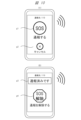
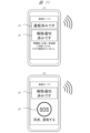
- Fig. 10 shows an example of a screen display on the display of the mobile terminal 1.
- Fig. 10 (A) shows an example of a display when an automatic report 1002 is sent by the automatic report function F1.
- This screen has an SOS button g1 for sending the automatic report 1002 to a report destination (e.g., 119), and a cancel button g2 for canceling the sending of the automatic report 1002.
- the mobile terminal 1 displays this screen, for example, together with a countdown, and when a button is pressed by the user U1 during the countdown time, the mobile terminal 1 performs processing according to the pressed button.
- the mobile terminal 1 automatically sends the automatic report 1002 after the countdown time has elapsed.
- FIG. 10 shows an example of the display when the release notification 1003 is sent by the release notification function F2.
- This screen has an indication g3 indicating that the automatic report 1002 has been sent, and a release button g4 for generating the release notification 1003.
- the mobile terminal 1 may display this screen when it determines that the condition of the user U1 has improved, and send the release notification 1003 when the user U1 presses the release button g4.
- FIG. 11 shows another example of the screen.
- (A) of FIG. 11 is an example of the display after the release notification 1003 has been sent.
- this screen also has a display g5 indicating that the release notification 1003 has been sent.
- FIG. 11 is an example of a screen in a modified example.
- this screen has an SOS button g6 for making another automatic report 1002.
- the automatic report 1002 occurs after the user U1 falls, and then the release notification 1003 occurs in response to a determination that the user U1 has returned to a normal state.
- the SOS button g6 may be displayed.
- FIG. 12 shows another example screen.
- (A) of FIG. 12 is an example screen when an incoming call is received from a caller related to the report destination during step S802 in FIG. 8 described above.
- This screen has display g3 indicating that an automatic report 1002 has been sent, and display g7 indicating that an incoming call has been received from a caller related to the report destination as a contact from a third party.
- Display g7 has, for example, the caller's telephone number, and an indication that the caller's telephone number is the number of a caller related to the report destination.
- FIG. 12 is an example of a screen that appears after user U1 answers a call from a caller related to the call destination during step S802 in FIG. 8 described above.
- This screen has a highlight g8 indicating that an automatic call 1002 has been sent, and a display g9 of the history of responses to phone numbers from callers related to the call destination.
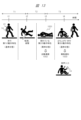
- [Situation assessment using release notification function] 13 is a supplementary explanatory diagram illustrating an example of the determination of the state 1001 of the user U1 by the release notification function F2.
- the determination of the state of the user U1 by the release notification function F2 may have a different processing algorithm from the determination of the state of the user U1 by the automatic report function F1.
- the determination of the state 1001 of an abnormality or the like by the automatic report function F1 is made by comparing the motion characteristics before and after an impact such as a fall.
- the determination of the state of the user U1 during additional monitoring by the release notification function F2 is made by further determining the change in the motion characteristics on the time axis with respect to the motion characteristics at the time (second time) after the impact due to the fall or the like.
- the horizontal axis is time.
- user U1 carrying mobile terminal 1 is walking and in a normal state.
- user U1 falls or the like, and mobile terminal 1 senses the impact caused by the fall or the like.
- user U1 has a first motion characteristic based on the sensing.
- user U1 has a second motion characteristic based on the sensing.
- user U1 is in a state where he has fallen to the ground.
- automatic reporting function F1 of mobile terminal 1 determines that user U1 is in an abnormal state 1001 or the like. Then, mobile terminal 1 issues an automatic report 1002.
- the release notification function F2 determines whether the user U1 has returned/improved from the abnormal state 1001 to a normal state based on a comparison between the second behavior characteristic at the second time T2 and the third behavior characteristic at the third time T3. If it is determined that the user U1 has returned to the normal state, the mobile terminal 1 transmits the release notification 1003.
- user U1 may input into mobile terminal 1 a voice input indicating that there is no problem or that the report should be cancelled, and mobile terminal 1 may then perform voice recognition of the input voice, identify user U1 from his/her voiceprint, and determine whether automatic report 1002 should be cancelled from words etc. resulting from the voice recognition, and send a cancellation notice 1003.
- FIG. 14 shows, as a supplementary explanatory diagram, an example of adjustment and control according to the remaining battery level of the mobile terminal 1 in steps S907 and S908 in FIG. 9.
- the horizontal axis in FIG. 14 is time.
- FIG. 14 (A) shows a case where the remaining battery level is, for example, 75% when the user U1 enters an abnormality state 1001 at time tA and an automatic report 1002 occurs.
- the mobile terminal 1 transitions to a battery save mode (step S907).
- the mobile terminal 1 adjusts the time interval for periodic alert output, etc. according to the remaining battery level.
- the mobile terminal 1 performs at least one of an alert output to the surroundings, a notification to the surrounding devices, or a second automatic report 1002.
- the mobile terminal 1 similarly performs at least one of an alert output to the surroundings, a notification to the surrounding devices, or a second automatic report 1002.
- periodic processing is similarly performed at time intervals TC1.
- the remaining battery level is, for example, 30%.
- the mobile terminal 1 transitions to a battery save mode (step S907).
- the mobile terminal 1 adjusts the time interval for periodic alert output, etc., according to the remaining battery level.
- the remaining battery level is lower than in (A), so the time interval TC2 is set longer than the time interval TC1.
- the mobile terminal 1 performs at least one of outputting an alert to the surroundings, notifying surrounding devices, or making another automatic report 1002.
- time interval TC2 After time interval TC2 has elapsed from time tC1, at time tC2, the mobile terminal 1 performs at least one of outputting an alert to the surroundings, notifying surrounding devices, or making another automatic report 1002. Similarly, periodic processing is performed every time interval TC2 thereafter.
- the mobile terminal 1 may also determine the time range (from start to end) for performing the periodic processing at the fifth hour according to the remaining battery level.
- the mobile terminal 1 may also determine and decide when to transition to the battery save mode after sending the automatic report 1002 according to the remaining battery level. For example, the mobile terminal 1 may transition to the battery save mode when the remaining battery level falls below a predetermined level.
- the mobile terminal 1 may select, as the above-mentioned periodic processing, whether to only output an alert to the surroundings, only notify surrounding devices via short-range communication, only make another automatic report 1002, or perform two or more of these. For example, when the remaining battery level is equal to or greater than a first threshold, three or two processes may be performed, when the remaining battery level is less than the first threshold, only one process may be performed, and when the remaining battery level is less than a second threshold that is smaller than the first threshold, all processes may be stopped and only a call back from the report destination may be waited for.
- the release notification 1003 is automatically sent according to the judgment of the mobile terminal 1 even if there is no operation input by the user U1, but this is not limited to this, and may be sent via the operation input of the user U1.
- the mobile terminal 1 judges that the previous automatic report 1002 should be released, it outputs (for example, a screen display or a voice) to the user U1 that the release is to be released before sending the release notification 1003 to the report destination.
- the mobile terminal 1 judges that the previous automatic report 1002 should be released, it outputs (for example, a screen display or a voice) to the user U1 that the release is to be released before sending the release notification 1003 to the report destination.
- it may be sent via the operation of pressing the release button g4 on the screen.
- the mobile terminal 1 When the user U1 performs a confirmation/affirmative operation, for example, pressing the release button g4, the mobile terminal 1 sends the release notification 1003 to the report destination. If the user U does not perform the affirmative operation, the mobile terminal 1 does not send the release notification 1003.
- the user can set detailed functions related to the release notification function F2. For example, the user can select whether the release notification 1003 is to be sent automatically or via the operation of pressing the release button g4.
- release notification 1003 may be similarly applied to these derivative reports, etc.
- 1...Mobile terminal 1A...Smartphone, 1B...Smartwatch, 2...System to report to, 3...Operator's system, 9...Communication network, F1...Automatic reporting function, F2...Release notification function, 1001...Emergency/abnormal/problem status, 1002...Automatic reporting, 1003...Release notification, 1004...Related information, U1...User, U2...Responder.
Landscapes
- Business, Economics & Management (AREA)
- Emergency Management (AREA)
- Physics & Mathematics (AREA)
- General Physics & Mathematics (AREA)
- Alarm Systems (AREA)
Abstract
誤通報などの場合にも、好適な対応が可能な技術を提供する。携帯端末1は、携帯端末1の状態に応じて、ユーザU1が緊急または異常または問題の状態1001である第1の状態であると判定した場合に、所定の通報先である第1の通報先に自動通報1002である第1の通報を自動的に行う自動通報機能F1を有する。携帯端末1は、自動通報1002の後の時間において、携帯端末1の状態を監視し、第1の状態が解消したかどうか、または、第1の通報が誤通報であったかどうかを判定し、解消した、または、誤通報であった、と判定した場合には、第1の通報に関する解除を伝えるための解除通知1003を第1の通報先に行う解除通知機能F2を有する。
Description
本開示は、携帯端末などの技術に関する。
スマートフォンやスマートウォッチなどの携帯端末(言い換えると情報端末装置など)は、当該携帯端末を所持するユーザの緊急時(言い換えると異常時、問題発生時など)に自動的に通報を行う機能(自動通報機能と記載する場合がある)を備えるものがある。例えば、最近のスマートフォンは、衝撃などに対応した加速度などのセンシングおよび判断に基づいて、ユーザが例えば転倒して立てない状態などを、緊急/異常/問題の状態として判定・検知する。そして、スマートフォンは、その状態に応じて、警察や救急などの所定の通報先へ、自動的に通報(言い換えると、自動通報、SOS、救難信号など)を実行・送信する。このような携帯端末の自動通報機能によれば、ユーザの緊急時にすぐに救難などの対応がしやすくなり、ユーザの命を救うことができる場合もある。
先行技術例として、特開2022-37048号公報(特許文献1)が挙げられる。特許文献1には、モバイルデバイスが、衝撃と、衝撃前の時間でのユーザの第1の動作特性と、衝撃後の時間でのユーザの第2の動作特性とに基づいて、ユーザの転倒を判定し、それに応じて、ユーザが転倒したことを示す通知を生成する旨が記載されている。
しかしながら、上記携帯端末の自動通報機能は、ユーザに異常などが無い状態の場合でも、自動通報が誤通報として生じる場合がある。例えば、ユーザがスキー等の運動をしていた場合に、ユーザのスマートフォンが、衝撃のセンシング等に基づいて、異常状態と判定し、実際には異常や問題が無い状態でも、自動通報が誤通報として生じる場合がある。
上記携帯端末の自動通報機能による誤通報が生じた場合には、ユーザが困る場合がある。また、警察や救急等の通報先のシステムも、誤通報への対応にリソースが必要となり、困る場合がある。
特許文献1のような先行技術例では、自動通報後の処理や、誤通報の場合の処理については、記載されていない。
本開示の目的は、上記携帯端末の自動通報機能に関する技術に関して、誤通報などの場合にも、好適な対応が可能な技術を提供することである。
本開示のうち代表的な実施の形態は以下に示す構成を有する。実施の形態の携帯端末は、自動通報機能を有する携帯端末であって、前記自動通報機能は、前記携帯端末の状態に応じて、前記携帯端末を携帯するユーザが緊急または異常または問題の状態である第1の状態であると判定した場合に、所定の通報先である第1の通報先に自動通報である第1の通報を自動的に行う機能であり、前記携帯端末は、前記自動通報が行われた場合に、前記自動通報の後の時間において、前記携帯端末の状態を監視し、前記第1の状態が解消したかどうか、または、前記第1の通報が誤通報であったかどうかを判定し、解消した、または、前記誤通報であった、と判定した場合には、前記第1の通報に関する解除を伝えるための解除通知を前記第1の通報先に行う。
本開示のうち代表的な実施の形態によれば、上記携帯端末の自動通報機能に関する技術に関して、誤通報などの場合にも、好適な対応が可能となる。上記した以外の課題、構成および効果等については、発明を実施するための形態において示される。
以下、図面を参照しながら本開示の実施の形態を詳細に説明する。図面において、同一部には原則として同一符号を付し、繰り返しの説明を省略する。図面において、構成要素の表現は、発明の理解を容易にするために、実際の位置、大きさ、形状、範囲等を表していない場合がある。
説明上、プログラムによる処理について説明する場合に、プログラムや機能や処理部等を主体として説明する場合があるが、それらについてのハードウェアとしての主体は、プロセッサ、あるいはそのプロセッサ等で構成されるコントローラ、装置、計算機、システム等である。計算機は、プロセッサによって、適宜にメモリや通信インタフェース等の資源を用いながら、メモリ上に読み出されたプログラムに従った処理を実行する。これにより、所定の機能や処理部等が実現される。プロセッサは、例えばCPU/MPUやGPU等の半導体デバイス等で構成される。処理は、ソフトウェアプログラム処理に限らず、専用回路でも実装可能である。専用回路は、FPGA、ASIC、CPLD等が適用可能である。
プログラムは、対象計算機に予めデータとしてインストールされていてもよいし、プログラムソースから対象計算機にデータとして配布されてもよい。プログラムソースは、通信網上のプログラム配布サーバでもよいし、非一過性のコンピュータ読み取り可能な記憶媒体、例えばメモリカードやディスクでもよい。プログラムは、複数のモジュールから構成されてもよい。コンピュータシステムは、複数台の装置によって構成されてもよい。コンピュータシステムは、クライアント・サーバシステム、クラウドコンピューティングシステム、IoTシステム等で構成されてもよい。各種のデータや情報は、例えばテーブルやリスト等の構造で構成されるが、これに限定されない。識別情報、識別子、ID、名前、番号等の表現は互いに置換可能である。
[課題等]
課題等について補足する。ユーザが転倒などした場合、携帯端末の自動通報機能は、衝撃検知に基づいて、自動通報を発生させる。例えば、携帯端末は、大きなアラート音を鳴らし、本体を振動させ、カウントダウンを開始する。ユーザがカウントダウンを止めない場合、携帯端末は、ユーザが重大な事故に遭っている等、緊急/異常/問題の状態であると判断し、自動的に緊急通報サービス等に自動通報を発信する。
課題等について補足する。ユーザが転倒などした場合、携帯端末の自動通報機能は、衝撃検知に基づいて、自動通報を発生させる。例えば、携帯端末は、大きなアラート音を鳴らし、本体を振動させ、カウントダウンを開始する。ユーザがカウントダウンを止めない場合、携帯端末は、ユーザが重大な事故に遭っている等、緊急/異常/問題の状態であると判断し、自動的に緊急通報サービス等に自動通報を発信する。
しかしながら、上記自動通報が発信された後、ユーザに異常や問題が無い状態、例えば転倒したものの怪我が無い状態などの場合や、ユーザが操作を誤って自動通報をしてしまった場合などがある。その場合には、通報先からユーザへの救難等の対応は不要であり、その自動通報は、ユーザおよび通報先にとって、基本的に不要なものとなる。
従来、上記不要な自動通報を受けた通報先(例えば警察や救急)は、対応者がユーザに状態を確認する等の対応を行う必要があり、時間や手間等、限られたリソースを消費する。
そこで、上記不要な自動通報が生じた場合に、あるいは、自動通報後にユーザの状態が改善した場合に、その自動通報を解除/キャンセルすること、が有用である。言い換えると、自動通報が生じたものの、ユーザに異常や問題が無いこと、通常状態に復帰したこと、あるいは、誤通報であったこと、救難等の対応を必要としていないこと等を、通報先に伝えることが有用である。
実施の形態は、上記自動通報の発生後に、上記自動通報を解除する仕組み、後述の通報解除機能、を有する。これにより、ユーザは安心でき、通報先も対応のための時間や手間等を低減でき、限られたリソースの消費を低減できる。
なお、自動通報の通報先の電話番号の例は以下である。
日本において、110番:警察、119番:救急。
中国において、110番:警察、120番または999番:救急。
米国において、911番:警察・救急。
欧州において、112番:警察・救急。
日本において、110番:警察、119番:救急。
中国において、110番:警察、120番または999番:救急。
米国において、911番:警察・救急。
欧州において、112番:警察・救急。
<実施の形態1>
図1~図14を用いて、本開示の実施の形態1の携帯端末および通報解除方法について説明する。実施の形態1の携帯端末は、図1等に示すように、自動通報機能F1を備える携帯端末1である。実施の形態1の通報解除方法は、実施の形態1の携帯端末によって実行される方法である。実施の形態1の携帯端末1は、携帯端末1の状態に応じて、ユーザU1が緊急または異常または問題の状態1001である第1の状態であると判定した場合に、所定の通報先(通報先のシステム2)である第1の通報先に、自動通報1002である第1の通報を自動的に行う自動通報機能F1を有する。携帯端末1は、自動通報1002の後の時間において、携帯端末1の状態を監視し、第1の状態が解消したかどうか、または、第1の通報が誤通報であったかどうかを判定し、解消した、または、誤通報であった、と判定した場合には、第1の通報に関する解除を伝えるための解除通知1002を第1の通報先に行う解除通知機能F2を有する。
図1~図14を用いて、本開示の実施の形態1の携帯端末および通報解除方法について説明する。実施の形態1の携帯端末は、図1等に示すように、自動通報機能F1を備える携帯端末1である。実施の形態1の通報解除方法は、実施の形態1の携帯端末によって実行される方法である。実施の形態1の携帯端末1は、携帯端末1の状態に応じて、ユーザU1が緊急または異常または問題の状態1001である第1の状態であると判定した場合に、所定の通報先(通報先のシステム2)である第1の通報先に、自動通報1002である第1の通報を自動的に行う自動通報機能F1を有する。携帯端末1は、自動通報1002の後の時間において、携帯端末1の状態を監視し、第1の状態が解消したかどうか、または、第1の通報が誤通報であったかどうかを判定し、解消した、または、誤通報であった、と判定した場合には、第1の通報に関する解除を伝えるための解除通知1002を第1の通報先に行う解除通知機能F2を有する。
[通報システム]
図1は、実施の形態1の携帯端末1を含んだシステム全体の構成例を示す。図1のシステム(説明上、通報システムとも記載する)は、ユーザU1の携帯端末1と、警察や救急などの通報先のシステム2とが、通信網9を介して接続されるシステムである。また、図2には、実施の形態1の通報解除方法の概要として、図1の携帯端末1と通報先のシステム2との間での主なシーケンスを示している。
図1は、実施の形態1の携帯端末1を含んだシステム全体の構成例を示す。図1のシステム(説明上、通報システムとも記載する)は、ユーザU1の携帯端末1と、警察や救急などの通報先のシステム2とが、通信網9を介して接続されるシステムである。また、図2には、実施の形態1の通報解除方法の概要として、図1の携帯端末1と通報先のシステム2との間での主なシーケンスを示している。
ユーザU1は、実施の形態1の携帯端末1を携帯し、本通報システムでの自動通報機能F1や解除通知機能F2などの機能を利用する対象者である。携帯端末1には、自動通報機能F1や解除通知機能F2が実装されている。携帯端末1は、例えばスマートフォン1Aやスマートウォッチ1Bなどが挙げられ、詳細については限定しない。ユーザU1は、スマートフォン1Aとスマートウォッチ1Bとの両方を所持してもよい。スマートフォン1Aとスマートウォッチ1Bが通信で連携してもよい。
ユーザU1は、例えば歩行や運動時に転倒して倒れる、事故に遭う等、緊急/異常/問題の状態1001になる場合がある。この状態1001は、自動通報1002の対象となる状態である。
携帯端末1は、自動通報機能F1によって、ユーザU1のこのような異常等の状態1001(第1の状態)を判定・検知する(図2でのステップS1)。すると、携帯端末1は、自動通報機能F1によって、自動通報1002を、所定の通報先のシステム2へ送信する(図2でのステップS2)。
警察や救急などの通報先のシステム2は、電話機2001、サーバ2002、PC2003、携帯端末2004などを備えており、自動通報1002を受信する(図3でのステップS2)。対応者U2であるユーザU2は、自動通報1002を受けて、確認や救難などの対応を行う人である。なお、対応者U2が、スマートフォンなどの携帯端末2004を携帯していてもよく、その携帯端末2004で自動通報1002を受けてもよい。対応者U2による対応は、ユーザU1への呼びかけ、状態確認、救難などの手配、などが挙げられ、詳細については限定しない。
ユーザU1の携帯端末1は、自動通報1002がされた後の時間において、ユーザU1の異常等の状態1001が解消・改善したかどうか、あるいは、先に為された自動通報1002が誤通報であったかどうか等を判定する(図2でのステップS4)。携帯端末1は、解消した、あるいは誤通報であった、と判定した場合、先の自動通報1002(それに対応付けられた状態1001)に関する解除のための解除通知1003を、先の自動通報1002と同じ通報先のシステム2へ送信する(図2でのステップS5)。
通報先のシステム2は、解除通知1003を受信し、対応者U2は、その解除通知1003を受けて、先の自動通報1002に関する解除などの対応を行う(図2のステップS6)。
自動通報1002は、例えばモバイル網を用いた電話(言い換えると音声データ通信)による通報であるが、詳細を限定しない。この自動通報1002には、例えば文字や音声や画像などのデータが伴ってもよい。
また、図1の例では、通信網9に事業者のシステム3が接続されており、事業者のサーバ3001やPC3002を有する。事業者のシステム3が、ユーザU1の携帯端末1と通信して一部の機能を提供してもよいし、通報先のシステム2と通信して一部の機能を提供してもよいし、ユーザU1の携帯端末1と通報先のシステム2との間に介在してもよい。例えば、クラウドコンピューティングシステムまたはクライアント・サーバシステムとして、事業者のサーバ3001が、自動通報1002に係わる状態の検知や判定などの処理を行ってもよいし、解除通知1003に係わる状態の検知や判定などの処理を行ってもよい。
図1では、後述する構成要素もあわせて図示している。ユーザU1の携帯端末1に対し、通信網9を介して、家族や知人等の他者のユーザU3の携帯端末4001を有する。あるいは、ユーザU1の携帯端末1に対し、周囲(比較的近い距離範囲内)に、家族や知人等の他者のユーザU3の携帯端末4001を有してもよいし、不特定の他者のユーザU3の携帯端末4001を有してもよい。また、ユーザU1の携帯端末1に対し、周囲(比較的近い距離範囲内)に、不特定の任意のデバイス4002があってもよい。周囲のデバイス4002は、例えば監視カメラや施設のサーバ、無線基地局などが挙げられる。
[通報解除方法]
図2は、実施の形態1の通報解除方法の概要を示すシーケンス図である。ステップS1で、ユーザU1の携帯端末1の自動通報機能F1は、各種センサ等を用いたセンシングに基づいて、ユーザU1の転倒等の緊急/異常/問題の状態1001を判定・検知する。ステップS2で、携帯端末1の自動通報機能F1は、ユーザU1の状態1001を伝えて救難などを求めるための自動通報1002を、所定の通報先のシステム2へ発信する。
図2は、実施の形態1の通報解除方法の概要を示すシーケンス図である。ステップS1で、ユーザU1の携帯端末1の自動通報機能F1は、各種センサ等を用いたセンシングに基づいて、ユーザU1の転倒等の緊急/異常/問題の状態1001を判定・検知する。ステップS2で、携帯端末1の自動通報機能F1は、ユーザU1の状態1001を伝えて救難などを求めるための自動通報1002を、所定の通報先のシステム2へ発信する。
ステップS3で、通報先のシステム2は、自動通報1002を受信し、対応を行う。例えば、対応者U2は、自動通報1002を確認し、発信元であるユーザU1の携帯端末1へ折り返しの連絡を行い、ユーザU1の状態の確認などを行う。なお、ステップS3の対応は、図2では即時に行われた場合を図示しているが、必ずしも即時に行われるとは限らない。
ステップS4で、携帯端末1は、解除通知機能F2によって、自動通報1002後の時間において、ユーザU1の緊急/異常/問題の状態1001が解消/改善したかどうか、あるいは誤通報であったかどうか等を、追加センシングを含む追加監視に基づいて、判定・検知する。
ステップS5で、携帯端末1の解除通知機能F2は、ステップS4で解消または誤通報と判定した場合に、先の自動通報1002の通報先と同じ通報先に、解除通知1003(言い換えるとSOSキャンセル通知)を送信する。ステップS6で、通報先のシステム2は、解除通知1003を受信し、対応者U2は、その解除通知1003から、先の自動通報1002に関する解除(SOSキャンセル)の対応を行う。
[自動通報機能]
まず、自動通報1002を行うための基本前提的な機能として、図1の自動通報機能F1の構成例を説明する。この自動通報機能F1は、例えば特許文献1に記載の技術を同様に適用できるが、これに限定されない。実施の形態1では、自動通報機能F1としては、特許文献1に記載の技術を同様に適用した場合を説明する。
まず、自動通報1002を行うための基本前提的な機能として、図1の自動通報機能F1の構成例を説明する。この自動通報機能F1は、例えば特許文献1に記載の技術を同様に適用できるが、これに限定されない。実施の形態1では、自動通報機能F1としては、特許文献1に記載の技術を同様に適用した場合を説明する。
この自動通報機能F1では、携帯端末1は、各種のセンサ等を用いて、携帯端末1またはユーザU1の動き、衝撃などをセンシングする。携帯端末1は、検出した衝撃の前の時間でのユーザU1の動作特性と、検出した衝撃の後の時間でのユーザU1の動作特性とを比較して、ユーザU1が転倒等したかどうかを判定する。例えば、衝撃前の動作特性では、ユーザU1が周期的な動きで普通に歩いていたが、衝撃後の動作特性では、体の向きが変化し変則的な動きになっている。携帯端末1は、そのような動作特性の変化から、ユーザU1の転倒等の事象や状態を推定できる。携帯端末1は、ユーザU1が転倒等したと判定した場合、すなわちユーザU1が緊急/異常/問題の状態1001であると判定した場合、自動通報1002を生成する。自動通報1002は、ユーザU1が転倒等によって緊急または異常または問題などの状態1001であることを表す通報である。
なお、特許文献1の技術の場合、図12の状態遷移図に示されるように、SOS通報をする前に、一定時間待機し(1206b)、判断を行う。特許文献1の技術は、その待機の間に、通報の必要が有ると判断した場合には、SOS通報を出し(1202)、ノミナル状態(1202)に戻る。また、特許文献1の技術は、その待機の間に、通報の必要が無いと判断した場合には、SOS通報をキャンセルし(1210)、SOSを出さずにノミナル状態(1202)に戻る。特許文献1の技術の場合、SOS通報(1202)を出した後の何らかの処理については開示されていない。
[解除通知機能]
次に、実施の形態1での特徴的な機能である、解除通知1003を行うための機能である、解除通知機能F2について説明する。
次に、実施の形態1での特徴的な機能である、解除通知1003を行うための機能である、解除通知機能F2について説明する。
実施の形態1では、上記自動通報機能F1によって、自動通報1002(図1)が一旦出力された後の時間において、携帯端末1の解除通知機能F2は、携帯端末1およびユーザU1の動き等の状態の監視を継続する。携帯端末1の解除通知機能F2は、ユーザU1の緊急/異常/問題の状態1001が解消したかどうか、あるいは、先の自動通報1002が、ユーザU1に問題無い状態での誤通報であったかどうか、等を判断する。携帯端末1の解除通知機能F2は、例えば、ユーザU1が転倒後に立ち上がり再度歩行し始める等の動きを検出した場合、異常等の状態1001が解消した、あるいは、そもそも異常等の状態1001ではなく誤通報に該当した、と判定する。そして、携帯端末1の解除通知機能F2は、先の自動通報1002の通報先と同じ通報先に、先の自動通報1002に関するユーザU1の異常等の状態1002が解消した旨あるいは誤通報であった旨を伝えるための解除通知1003を生成し、当該解除通知1003を自動的に発信する。
実施の形態1では、自動通報1002の後の時間における解除通機能F2による通報解除判断処理としては、自動通報機能F1による自動通報判断処理(特に衝撃の前後の時間での動作特性の比較判定)と同様の処理に加え、使用するセンサ等のパラメータを増やし、追加センシングを含む追加監視処理を行う。実施の形態1では、増やすセンサ等のパラメータとして、音声入力・音声認識によるユーザU1の状態の判断を有する。携帯端末1は、マイクを含む音声入力・音声認識機能をオン状態にする。このオン状態で、携帯端末1は、ユーザU1が自分の状態あるいは通報解除を伝えるための音声を入力・認識してもよいし、携帯端末1の周囲の音声を拾って、状態を判断してもよい。
携帯端末1は、追加センシングに基づいて、ユーザU1の異常等の状態1001が解消した、または誤通報であったと判定した場合、解除通知1003を先の通報先に発信する。
上記のように、実施の形態1では、自動通報機能F1によるセンシングを含むユーザU1の状態の判断の処理と、自動通報1002後の解除通知機能F2による追加センシングを含むユーザU1の状態の判断の処理とは、一部異なり、後者は追加センシングを含む。
[関連情報]
また、携帯端末1の解除通知機能F2は、解除通知1003に、当該解除通知1003と先の自動通報1002とを関連付け、先の自動通報1002を通報先が同定しやすくするための情報である関連情報1004を含める、または添付等するようにする。この関連情報1004は、例えば、先の自動通報1002が、自動通報機能F1による衝撃の検知に基づいて発生した自動通報であったこと、先の自動通報1002とこの解除通知1003とが関連していること、等を表す情報である。
また、携帯端末1の解除通知機能F2は、解除通知1003に、当該解除通知1003と先の自動通報1002とを関連付け、先の自動通報1002を通報先が同定しやすくするための情報である関連情報1004を含める、または添付等するようにする。この関連情報1004は、例えば、先の自動通報1002が、自動通報機能F1による衝撃の検知に基づいて発生した自動通報であったこと、先の自動通報1002とこの解除通知1003とが関連していること、等を表す情報である。
この関連情報1004には、例えば、デバイスすなわち携帯端末1のIDや通信アドレスなどの固有情報、電話番号、位置情報、ユーザU1の氏名などの利用者情報、先の自動通報1002の発信の日時情報(例えば日時分秒)、発信内容情報などのうち、少なくとも1つの情報を有する。
通報先のシステム2は、上記解除通知1003を受信した場合、その解除通知1003に含まれる関連情報1004から、この解除通知1003と関連した先の自動通報1002を同定できる。そして、通報先のシステム2は、先の自動通報1002が、不要となったまたは誤通報であったため、解除できることを、認識できる。対応者U2は、先の自動通報1002への救難などの対応が不要である、または、ユーザU1の状態が軽微であるため簡易な対応のみでよい、等と判断できる。
[解除通知機能F2の詳細な機能]
また、解除通知機能F2の詳細な機能としては、以下が挙げられる。
また、解除通知機能F2の詳細な機能としては、以下が挙げられる。
(1)携帯端末1は、携帯端末1が通報先に自動通報1002を行った旨(言い換えると自動通報済み)を、携帯端末1から出力して、ユーザU1に伝える機能を有する。この出力は、少なくとも表示や音声で行われる。
(2)携帯端末1は、自動通報1002の後に、解除通知1003のための追加監視を開始する。この追加監視では、前述のセンサを増やした追加センシングの他に、近距離通信をオン状態にして、携帯端末1の周囲のデバイスと近距離通信し、周囲のデバイスに、ユーザU1の状態を通知する。
(3)携帯端末1は、自動通報1002の後の追加監視の時間に、通報先や他の番号から、当該ユーザU1の携帯端末1に連絡の着呼を受けた場合に、その発信元の番号が、所定の通報先の番号であるか、所定の通報先と関連する発信元の番号であるか、無関係の第三者の番号であるか等を、自動的にサーチ等によって判断する。そして、携帯端末1は、判断した番号に応じて、自動的に、対処処理を分岐する。例えば、携帯端末1は、どのような連絡先(発信元)であるかを、携帯端末1から出力して明らかにする。
(4)携帯端末1は、自動通報1002の後の追加監視の時間に、ユーザU1の異常等の状態1001が継続しているか、通常状態に復帰したかどうか等の判断を継続し、異常等の状態1001が継続していると判定した場合には、再度、所定の通報先へ自動通報1002を発信する等の処理を行う。また、携帯端末1は、そのような場合には、携帯端末1からアラートを出力してもよい。
また、携帯端末1は、そのような場合には、所定の連絡先とは異なる、予め設定された連絡先、例えば家族や知人等のユーザU3の携帯端末4001(図1)に対応した連絡先へ、ユーザU1が異常等の状態1001である旨の連絡1011を行ってもよい。当該連絡1011を携帯端末4001で受けたユーザU3は、ユーザU1が、自動通報1002後にも異常等の状態1001である旨を認識できる。
また、携帯端末1は、そのような場合には、近距離通信に基づいて、周囲の第三者の携帯端末4001や任意のデバイス4002へ、ユーザU1が異常等の状態1001である旨の通知1012を発信してもよい。これらの周囲のデバイスは、当該通知1012の近距離通信を受け入れ可能な任意のデバイスである。当該周囲のデバイスは、当該通知1012を受けた場合には、自動通報1002後で救難を必要としているユーザU1が近くにいること等を認識できる。
(5)携帯端末1は、追加監視の時間に、ユーザU1の異常等の状態1001が継続していると判定した場合には、携帯端末1を、自動通報1002に関する動作以外の動作を控えて電力を温存するバッテリーセーブモードに移行させる。携帯端末1は、そのバッテリーセーブモードでは、定期的に、再度、通報先へ自動通報1002を行ってもよい。また、携帯端末1は、そのバッテリーセーブモードで、自動通報1002または他の種類の通信を定期的に繰り返す場合の時間間隔を、バッテリーの残量に応じて変えるように制御する。これにより、携帯端末1は、できるだけ長い時間、自動通報1002に関する待機、外部へ救難のための発信などを行うことができる。
[スマートフォン1A]
図3は、携帯端末1としてスマートフォン1Aの場合のハードウェア構成例を示す。スマートフォン1Aは、プロセッサ301、メモリ302、不揮発性メモリ303、カメラ・撮像部304、位置検知部305、姿勢検知部306、生体情報検知部307、第1無線通信部311、第2無線通信部312、第3無線通信部313、有線通信部314、ボタン・操作部315、ディスプレイ・表示部316、マイク・音声入力部317、スピーカ・音声出力部318、コネクタ・入出力インタフェース319、バッテリー・電源部320、振動部321、発光部322、等を備える。これらの構成要素は図示しないバス等のアーキテクチャで相互に接続されている。なお、これらの要素のすべてが必須というわけではなく、一部省略した構成でもよい。
図3は、携帯端末1としてスマートフォン1Aの場合のハードウェア構成例を示す。スマートフォン1Aは、プロセッサ301、メモリ302、不揮発性メモリ303、カメラ・撮像部304、位置検知部305、姿勢検知部306、生体情報検知部307、第1無線通信部311、第2無線通信部312、第3無線通信部313、有線通信部314、ボタン・操作部315、ディスプレイ・表示部316、マイク・音声入力部317、スピーカ・音声出力部318、コネクタ・入出力インタフェース319、バッテリー・電源部320、振動部321、発光部322、等を備える。これらの構成要素は図示しないバス等のアーキテクチャで相互に接続されている。なお、これらの要素のすべてが必須というわけではなく、一部省略した構成でもよい。
例えば不揮発性メモリ303には、必要なデータや情報として、OS、プログラム、デバイス情報、アプリ情報、利用者情報、通報先情報、状態情報、設定情報などが記憶されている。プログラムは、自動通報機能F1や解除通知機能F2を構成するためのコンピュータプログラムである。デバイス情報は、このスマートフォン1AのIDや通信アドレス情報等の固有情報がある。アプリ情報は、各種のアプリケーションプログラムの情報である。利用者情報は、このスマートフォン1Aを所持し利用するユーザU1の氏名などの情報である。通報先情報は、自動通報1002の際の所定の通報先の電話番号あるいはURL等の情報である。状態情報は、ユーザU1および携帯端末1の状態を表す情報である。設定情報は、機能に関するシステム設定情報やユーザ設定情報である。
デバイス情報、アプリ情報、および利用者情報等に含まれる情報の例は、スマートフォン1Aのデバイス固有番号、通信アドレス、ネットワークID、電話番号、ユーザU1の氏名、LINE(通話アプリ)等のアプリでのユーザID、等が挙げられる。状態情報は、例えば、ユーザU1の緊急/異常/問題の状態1001の有無、SOS(自動通報1002)の発信の有無、SOSに対する通報先からの連絡/応答の有無、解除通知1003の発信の有無、等が挙げられる。また、メモリ303または不揮発性メモリ303には、各時点の状態情報を含め、機能および処理に係わる履歴情報が保持されてもよい。
自動通報機能F1や解除通知機能F2は、OSの一部として実装されてもよいし、専用のアプリケーションプログラムとして実装されてもよい。アプリケーションとして実装される場合、そのアプリケーションは、ディスプレイ・表示部316にアプリケーション画面を表示してもよい。
スマートフォン1Aは、平板状の筐体において、前面側に、タッチパネルによるディスプレイ・表示部316や、カメラ・撮像部304としてインカメラ等を有する。スマートフォン1Aは、筐体の背面側に、カメラ・撮像部304としてアウトカメラ等を有する。スマートフォン1Aは、筐体の側面に、ボタン・操作部315、マイク・音声入力部317、スピーカ・音声出力部318、コネクタ・入出力インタフェース319等を有する。
プロセッサ301は、CPU等で構成され、スマートフォン1Aのコントローラを構成する。プロセッサ301は、メモリ302や不揮発性メモリ303のデータ・情報を読み書きする。プロセッサ301は、メモリ302上に読み出したプログラムに従った処理を実行する。これにより、各種の機能や処理部が実現される。
第1無線通信部311は、例えば無線LAN通信インタフェース(例えばWi-Fi)が実装されている。第2無線通信部312は、例えばモバイル網通信インタフェース(例えばLTE、4G、5Gなど)が実装されている。第3無線通信部313は、例えば近距離無線通信インタフェース(例えばBluetooth、NFCなど)が実装されている。有線通信部314は、有線通信インタフェース(例えばUSB)が実装されている。
ボタン・操作部315は、例えば電源ボタン、音量ボタンなどがあり、ユーザU1による操作入力を受ける部分である。プロセッサ301は、ボタン・操作部315での操作入力に応じて制御を行う。ディスプレイ・表示部316は、例えば液晶/有機ELタッチパネルを備える。マイク・音声入力部317は、マイクから音声を入力し、音声データに変換する。スピーカ・音声出力部318は、音声データから音声に変換してスピーカから出力する。コネクタ・入出力インタフェース319は、例えばUSBに対応したUSBコネクタ等がある。バッテリー・電源部320は、バッテリーに充電された電力を、各部へ供給する。振動部321は、必要に応じた振動を発生させる。発光部322は、必要に応じた発光を発生させる。
カメラ・撮像部304は、インカメラやアウトカメラを用いて撮影を行い、撮影画像データを得る。位置検知部305は、例えばGPS受信器を用いて、スマートフォン1Aの現在の位置情報(例えば緯度、経度、高度など)を取得する。また、位置検知部305は、無線基地局から無線基地局位置情報を取得してもよい。姿勢検知部306は、例えば地磁気センサ、ジャイロセンサ、加速度センサなどの各種のセンサを含み、スマートフォン1Aの現在の姿勢(例えば直交するX,Y,Zの3軸の向き)や角速度や加速度などの状態を検出する。また、携帯端末1に備えるセンサとして、他にも、照度センサ、近接センサ、測距センサ、視線検出センサなどがあってもよい。照度センサは、スマートフォン1Aの周囲の照度を検出する。近接センサは、スマートフォン1Aに対する他の物体の近接を検出する。測距センサは、スマートフォン1Aから外部の物体までの距離を測定する。視線検出センサは、スマートフォン1Aを見るユーザU1の視線を検出する。生体情報検知部307は、ユーザU1の生体情報を検出する。
スマートフォン1Aは、自動通報1002の際には、上記ディスプレイ・表示部316、スピーカ・音声出力部318、振動部321、発光部322等を利用して、所定の出力を行うようにしてもよい。
[スマートウォッチ1B]
図4は、携帯端末1としてスマートウォッチ1Bの場合のハードウェア構成例を示す。スマートウォッチ1Bは、プロセッサ401、メモリ402、不揮発性メモリ403、ボタン・操作部415、ディスプレイ・表示部416、マイク・音声入力部417、スピーカ・音声出力部418、位置検知部405、姿勢検知部406、生体情報検知部407、通信インタフェース411、バッテリー・電源部420、振動部421、発光部422、センサインタフェース431、等を備える。これらの構成要素は図示しないバス等のアーキテクチャで相互に接続されている。なお、これらの要素のすべてが必須というわけではなく、一部省略した構成でもよい。
図4は、携帯端末1としてスマートウォッチ1Bの場合のハードウェア構成例を示す。スマートウォッチ1Bは、プロセッサ401、メモリ402、不揮発性メモリ403、ボタン・操作部415、ディスプレイ・表示部416、マイク・音声入力部417、スピーカ・音声出力部418、位置検知部405、姿勢検知部406、生体情報検知部407、通信インタフェース411、バッテリー・電源部420、振動部421、発光部422、センサインタフェース431、等を備える。これらの構成要素は図示しないバス等のアーキテクチャで相互に接続されている。なお、これらの要素のすべてが必須というわけではなく、一部省略した構成でもよい。
例えば不揮発性メモリ403には、必要なデータや情報として、OS、プログラム、デバイス情報、アプリ情報、利用者情報、通報先情報、状態情報、設定情報などが記憶されている。プログラムは、自動通報機能F1や解除通知機能F2を構成するためのコンピュータプログラムである。デバイス情報は、このスマートウォッチ1BのID等の固有情報である。アプリ情報は、各種のアプリケーションプログラムの情報である。利用者情報は、このスマートウォッチ1Bを所持し利用するユーザU1の情報である。通報先情報は、自動通報1002の際の所定の通報先の電話番号、URL等の情報である。状態情報は、ユーザU1および携帯端末1の状態を表す情報である。設定情報は、機能に関するシステム設定情報やユーザ設定情報である。
デバイス情報、アプリ情報、および利用者情報等に含まれる情報の例は、スマートウォッチ1Bのデバイス固有番号、通信アドレス、ネットワークID、電話番号、ユーザU1の氏名、LINE(通話アプリ)等のアプリでのユーザID、等が挙げられる。状態情報は、例えば、ユーザU1の緊急/異常/問題の状態1001の有無、SOS(自動通報1002)の発信の有無、SOSに対する通報先からの連絡/応答の有無、解除通知1003の発信の有無、等が挙げられる。また、メモリ403または不揮発性メモリ403には、各時点の状態情報を含め、機能および処理に係わる履歴情報が保持されてもよい。
自動通報機能F1や解除通知機能F2は、OSの一部として実装されてもよいし、専用のアプリケーションプログラムとして実装されてもよい。アプリケーションとして実装される場合、そのアプリケーションは、ディスプレイ・表示部416にアプリケーション画面を表示してもよい。
スマートウォッチ1Bは、腕時計状の筐体において、前面側に、タッチパネルによるディスプレイ・表示部416等を有する。スマートウォッチ1Bは、筐体の側面に、ボタン・操作部415、マイク・音声入力部417、スピーカ・音声出力部418等を有する。
プロセッサ401は、CPU等で構成され、スマートウォッチ1Bのコントローラを構成する。プロセッサ401は、メモリ402や不揮発性メモリ403のデータ・情報を読み書きする。プロセッサ401は、メモリ402上に読み出したプログラムに従った処理を実行する。これにより、各種の機能や処理部が実現される。
通信インタフェース411は、例えば無線LAN、モバイル網、近距離無線通信などのうち1つ以上の通信インタフェースが実装された部分である。通信インタフェース411は、スマートフォン1Aと連携する場合にはその連携のための通信インタフェースが実装されている。
ボタン・操作部415は、例えばホームボタン、リセットボタンなどがあり、ユーザによる操作入力を受ける部分である。例えばホームボタンが押された場合、プロセッサ401は、スマートウォッチ1B本体を初期状態にし、ディスプレイ・表示部416には初期画面を表示するように、制御する。
ディスプレイ・表示部416は、例えば液晶/有機ELのタッチパネルを備える。マイク・音声入力部417は、マイクから音声を入力し、音声データに変換する。スピーカ・音声出力部418は、音声データから音声に変換してスピーカから出力する。バッテリー・電源部420は、バッテリーに充電された電力を、各部へ供給する。振動部421は、必要に応じた振動を発生させる。発光部422は、必要に応じた発光を発生させる。
位置検知部405は、例えばGPS受信器を用いて、スマートウォッチ1Bの現在の位置情報(例えば緯度、経度、高度など)を取得する。また、位置検知部405は、無線基地局から無線基地局位置情報を取得してもよい。姿勢検知部406は、例えば地磁気センサ、ジャイロセンサ、加速度センサなどの各種のセンサを含み、スマートウォッチ1Bの現在の姿勢(例えば直交するX,Y,Zの3軸の向き)や角速度や加速度などの状態を検出する。また、スマートウォッチ1Bに備えるセンサとして、他にも、照度センサ、近接センサ、測距センサ、視線検出センサなどがあってもよい。照度センサは、スマートウォッチ1Bの周囲の照度を検出する。近接センサは、スマートウォッチ1Bに対する他の物体の近接を検出する。測距センサは、スマートウォッチ1Bから外部の物体までの距離を測定する。視線検出センサは、スマートウォッチ1Bを見るユーザU1の視線を検出する。生体情報検知部407は、ユーザU1の生体情報を検出する。
センサインタフェース431は、センサを外部接続するインタフェースである。センサインタフェース431には、例えば身体情報計測センサ441が接続される。身体情報計測センサ441は、例えば、脈拍数、心拍数、または血流量などを測定する。当該センサは、例えば、ユーザU1の腕に対し、光を照射し、反射光を受光して、受光光量に応じた信号を生成する構成が挙げられる。その他、スマートウォッチ1Bにカメラ等を備えてもよい。
スマートウォッチ1Bは、自動通報1002の際には、上記ディスプレイ・表示部416、スピーカ・音声出力部418、振動部421、発光部422等を利用して、所定の出力を行うようにしてもよい。
[機能ブロック]
図5は、携帯端末1(ここではスマートフォン1Aの場合で説明する)のソフトウェアの機能ブロックの構成例を示す。図5の機能ブロックは、プロセッサ301による処理によって実現される。自動通報機能F1や解除通知機能F2は、主にコンピュータプログラムで実装されてもよい。自動通報機能F1や解除通知機能F2は、専用のアプリケーションで実装されてもよい。解除通知機能F2のみが専用のアプリケーションで実装されてもよい。また、解除通知機能F2は、自動通報機能F1と一体で実装されてもよい。
図5は、携帯端末1(ここではスマートフォン1Aの場合で説明する)のソフトウェアの機能ブロックの構成例を示す。図5の機能ブロックは、プロセッサ301による処理によって実現される。自動通報機能F1や解除通知機能F2は、主にコンピュータプログラムで実装されてもよい。自動通報機能F1や解除通知機能F2は、専用のアプリケーションで実装されてもよい。解除通知機能F2のみが専用のアプリケーションで実装されてもよい。また、解除通知機能F2は、自動通報機能F1と一体で実装されてもよい。
自動通報機能F1は、姿勢検知部305等のセンサによる出力値であるセンサ情報501を入力し、センサ情報501に基づいて、ユーザU1の異常等の状態を判定する処理502を行う。処理502は、ユーザU1が転倒等によって緊急/異常/問題の状態1001となったかどうかの判定である。なお、異常等の状態1001に該当しない場合の状態を、通常状態とも記載する。自動通報機能F1は、処理502の結果、異常等の状態1001である場合、通報先情報504等に基づいて、自動通報1002を生成・発信する処理503を行う。通報先情報504は、設定された所定の通報先の電話番号等の情報である。自動通報機能F1は、状態情報505(または履歴情報)には、ユーザU1が異常等の状態1001であること、および自動通報1002を行ったこと、等を表す情報を記載する。
解除通知機能F2は、自動通報機能F1による自動通報1002が生じた場合、例えば状態情報505が、異常状態、および自動通報有り(自動通報済み)を示している場合、解除通知1003のための処理を開始する。解除通知機能F2は、自動通報1002以後の時間において、センサのセンサ情報511を用いて監視を継続する処理512を行う。この監視を追加監視とも記載する。この追加監視は前述のように追加センシングを含む。
解除通知機能F2は、追加監視の結果、ユーザU1の緊急/異常/問題の状態1001が解消したかどうか、あるいは先の自動通報1002が誤通報であったか、を判定する処理513を行う。
解除通知機能F2は、上記判定の結果、解消した場合/誤通報であった場合には、前述の通報先情報504、および状態情報505等に基づいて、解除通知1003を生成し、先の自動通報1002の通報先と同じ通報先に、解除通知1003を発信する処理514を行う。この際、前述のように、この解除通知機能F2には、先の自動通報1002とこの解除通知1003を関連付けて先の自動通報1002を容易に同定できるようにするための関連情報1004を含ませる。
解除通知機能F2は、解除通知1003の送信後、ユーザU1の異常等の状態1001が解消したこと(言い換えると通常状態、解消状態)、および解除通知1003を発信したこと(解除通知済み)、を表す情報を、状態情報515(または履歴情報)に記載する。
[通報の関連付け・同定について]
自動通報機能F1による自動通報1002(1回目の通報として捉えてもよい)と、解除通知機能F2による解除通知1003(2回目の通報として捉えてもよい)との関連や同定について説明する。例えばそれらの2つの通報・通知、あるいはそれらを含む不特定多数の複数の通報・通知が、それらを受ける側である通報先のシステム2(図1)において、すみやかに同定できない場合、対応作業が手間となる。そのため、実施の形態1では、自動通報機能F1による自動通報1002と、解除通知機能F2による解除通知1003とが関連した情報であることを、通報先に伝えるための関連情報1004を、解除通知1003に含ませる。通知先のシステム2は、解除通知1003の関連情報1004から、それらの2つの通報・通知を容易にすみやかに関連付けて先の自動通報1002を同定できる。
自動通報機能F1による自動通報1002(1回目の通報として捉えてもよい)と、解除通知機能F2による解除通知1003(2回目の通報として捉えてもよい)との関連や同定について説明する。例えばそれらの2つの通報・通知、あるいはそれらを含む不特定多数の複数の通報・通知が、それらを受ける側である通報先のシステム2(図1)において、すみやかに同定できない場合、対応作業が手間となる。そのため、実施の形態1では、自動通報機能F1による自動通報1002と、解除通知機能F2による解除通知1003とが関連した情報であることを、通報先に伝えるための関連情報1004を、解除通知1003に含ませる。通知先のシステム2は、解除通知1003の関連情報1004から、それらの2つの通報・通知を容易にすみやかに関連付けて先の自動通報1002を同定できる。
自動通報1002および解除通知1003には、いずれも、携帯端末1のデバイスのID、電話番号、位置情報、ユーザU1の氏名、ユーザU1の状態、などの情報を伴わせる。解除通知1003には、先の自動通報1001との関連を表す関連情報1004を含ませる。
図15には、自動通報1002、解除通知1003、および関連情報1004などの構成例を図示している。(A)の例では、解除通知1003の情報内容のうち、デバイスID、電話番号、位置情報、利用者氏名などの情報部分は、関連情報1004に相当する。
関連情報1004の他の構成例としては、(B)に示すように、解除通知1003において、関連する自動通報1002の発信の日時などを指定・記述するようにしてもよい。また、解除通知1003は、関連する自動通報1002の内容のコピーのデータを持つようにしてもよい。
関連情報1004の他の構成例としては、(C)に示すように、自動通報1002や解除通知1003に、それぞれ、IDを付与しておき、関連情報1004では自動通報1002のIDを指し示すようにしてもよい。
また、通報先のシステム2は、上記情報、例えば電話番号などに基づいて、同じ電話番号による1つ以上の通報や通知は、関連する通報であるとして、グループやツリー、スレッド等の形式で出力してもよい。これにより、通報先の対応者U2は、受けた複数の通報の中で、自動通報機能F1による自動通報1002と、解除通知機能F2による解除通知1003とを、関連する通報として、容易に同定でき、当該通報への対応作業が容易となる。
[処理フロー]
次に、実施の形態1における詳細な処理フローを説明する。図6~図9は、携帯端末1の処理フロー例を示している。図6のフローは、部分的なフローであり、(1-1)とする。
次に、実施の形態1における詳細な処理フローを説明する。図6~図9は、携帯端末1の処理フロー例を示している。図6のフローは、部分的なフローであり、(1-1)とする。
[処理フロー(1-1)]
図6で、ステップS600で、最初、携帯端末1のユーザU1の状態は通常状態である。ステップS601で、携帯端末1は、自動通報機能F1により、通常監視として、第1時間でのセンシングを継続し、センサ情報を取得する。この第1時間は、下記衝撃を検知する前の時間を指す。例えば、第1時間では、ユーザU1の移動状況や振動状況(例えば静止、水平面の歩行、階段の歩行等)を表すセンサ情報が得られる。
図6で、ステップS600で、最初、携帯端末1のユーザU1の状態は通常状態である。ステップS601で、携帯端末1は、自動通報機能F1により、通常監視として、第1時間でのセンシングを継続し、センサ情報を取得する。この第1時間は、下記衝撃を検知する前の時間を指す。例えば、第1時間では、ユーザU1の移動状況や振動状況(例えば静止、水平面の歩行、階段の歩行等)を表すセンサ情報が得られる。
ステップS602で、携帯端末1は、特異情報のセンシングを行う。特異情報は、例えばある程度の大きさ以上の衝撃である。衝撃は、例えばユーザU1が転倒して地面にぶつかった際の衝撃や、ユーザU1が事故に遭って外部の物体がぶつかってきた際の衝撃である。
ステップS603で、携帯端末1は、特異情報(例えば衝撃)の検出後の、第2時間でのセンシングを継続し、センサ情報を取得する。この第2時間は、上記衝撃を検知した後の時間を指す。例えば、第2時間では、ユーザU1の移動状況や振動状況(例えば地面に倒れたまま動かない等)を表すセンサ情報が得られる。
ステップS604で、携帯端末1は、上記第1時間のセンサ情報、特異情報、および第2時間のセンサ情報に基づいて、ユーザU1の状態が、転倒や事故等の、緊急/異常/問題の状態1001であるかどうかを判定する。携帯端末1は、例えば、第1時間での動作特性と、第2時間での動作特性との比較で、変化が大きい場合に、転倒等の状態と推定できる。
ステップS604の結果、異常等の状態1001と判定した場合に、ステップS605で、携帯端末1は、上記第2時間での状況に基づいて、自動通報1002の要否を判断する。この判断は、携帯端末1が、ユーザU1が異常等の状態1001であると判定・推定したものの、実際にはユーザU1に問題無い状態である場合に、自動通報1002を行わないようにするためのものである。このステップS605では、例えば、携帯端末1は、ユーザU1に対し、アラートを出力し、カウントダウンを開始する(後述の図10の(A))。携帯端末1は、このカウントダウンの間、ユーザU1による操作入力(すなわち問題無いこと/自動通報が不要であることを表す確認入力)を受け付けて、その操作入力がある場合には、ユーザU1が問題無い状態であると判定する。そして、その場合、携帯端末1は、自動通報1002が不要であると判定する。他方、カウントダウンの間、ユーザU1による操作入力が無いまま、タイムアップした場合、携帯端末1は、ユーザU1が反応していないことから、自動通報1002が必要であると判定する。
なお、上記ステップS605の処理は、特許文献1の技術でいえば、図12での待機時間のSOSキャンセルの判断に相当する。
ステップS605の結果、ステップS606で、自動通報1002が必要とされた場合(Y)、ステップS607で、携帯端末1は、所定の通報先に、自動通報1002を発信する。携帯端末1は、自動通報1002には、当該自動通報1002を行う自デバイスである携帯端末1を特定できる情報を含めるようにする。この情報は、例えば、携帯端末1のID、電話番号、位置情報、ユーザU1の氏名、などである。また、携帯端末1は、自動通報1002には、携帯端末1のユーザU1の状況、すなわち判定した異常等の状態1001(例えば転倒して動かない状態)を表す情報を含めるようにする。
ステップS608で、携帯端末1は、上記自動通報1002を発信した事実や結果(自動通報有り、通報先、日時、通報内容など)を、状態情報505(図5)あるいは履歴情報に記載し、自デバイス内の不揮発性メモリ303等に保持する。また、携帯端末1は、ユーザU1に対し、自動通報1002を発信済みである旨を、携帯端末1から例えば画面表示や音声出力で出力する(後述の図10の(B))。
ステップS606で不要と判定した場合(S606-N)、例えばS601に戻り、同様の繰り返しである。ステップS608の後、次のフローに続く。
[処理フロー(1-2)]
図7は、続く処理フローとして(1-2)を示す。ステップS608からステップS701に続く。ステップS701で、携帯端末1は、上記自動通報1002の発生に伴い、解除通知機能F2による処理を開始する。詳しくは、ステップS607で自動通報1002を発信した後の時点から、解除通知機能F2による処理を開始してもよい。
図7は、続く処理フローとして(1-2)を示す。ステップS608からステップS701に続く。ステップS701で、携帯端末1は、上記自動通報1002の発生に伴い、解除通知機能F2による処理を開始する。詳しくは、ステップS607で自動通報1002を発信した後の時点から、解除通知機能F2による処理を開始してもよい。
ステップS702で、携帯端末1は、センサを用いたユーザU1の状態に関する監視を継続する。言い換えると、携帯端末1は、自動通報機能F1による監視を前述の通常監視とすると、解除通知機能F2による監視を追加監視(言い換えると通報後監視)として、その追加監視を開始する。この追加監視では、通常監視時のセンシングに対し、使用するセンサ種類等を増やす。例えば、増やすセンサとして、マイクを含む音声入力・音声認識や、NFC等の近距離通信機能がある。携帯端末1は、これらの追加センサを強制オンにする。この音声入力・音声認識は、例えば図3のマイク・音声入力部317で実現される。この近距離通信機能は、例えば図3の第3無線通信部313で実現される。
ステップS703で、携帯端末1は、ステップS702でオンにした追加センシングを含む追加監視によって、自動通報1002後から少なくとも所定の時間(ここでは第3時間とする)の間、ユーザU1の移動状況、振動状況、音声入力・音声認識の状況、近距離通信の状況などをセンシングし、第3時間でのセンサ情報(言い換えると時系列センサデータ)を検出・取得する。
追加センサとして音声入力・音声認識を用いる場合、例えば、ユーザU1が発している音声や携帯端末1の周囲の音声を、携帯端末1は、音声入力・音声認識によって音声データとして取得する。この音声データは、ユーザU1の状態を判断するための材料となる。
また、追加センサとして近距離通信を用いる場合、例えば、携帯端末1は、近距離通信によって周囲に信号を発信し、周囲の任意のデバイスから応答の信号を受信してもよい。
ステップS704で、携帯端末1は、上記ステップS703の第3時間のセンサ情報に基づいて、ユーザU1の状態が、異常等の状態1001から通常状態に復帰したかどうか、あるいは、そもそも誤通報であって通常状態のままであるかどうか、等を判定する。言い換えると、携帯端末1は、先の自動通報1002に関して、ユーザU1の状況が、救難などの対応を必要としない状況になったかどうか、異常等の状態1001が解消/改善されたかどうか、すなわち、先の自動通報1002を解除すべきかどうか、等を判定する。
上記ステップS704の判定の処理内容としては、ステップS604やステップS605の処理内容を同様に適用する他に、追加センサ情報を加味して判断する。例えば、先の自動通報1002の時点では、ユーザU1が転倒により地面に倒れていたとする。その後、ユーザU1の心身に問題無く、ユーザU1は立ち上がり、歩行し始めたとする。携帯端末1は、このような状況を判断・推定することで、ユーザU1が通常状態に復帰したと判定する(後述の図13)。また、例えば、自動通報1002後、ユーザU1が心身に問題無い旨を音声入力し、携帯端末1は、その音声入力から、ユーザU1が通常状態に復帰したと判定してもよい。
ステップS705で、携帯端末1は、上記ステップS704の結果でユーザU1が通常状態に復帰した場合(Y)にはステップS706に分岐し、復帰していない場合(N)には後述のステップS901に分岐する。
ステップS706で、携帯端末1は、先の自動通報1002(ステップS607)に関する解除通知1003を生成し、先の通報先へ発信する。この解除通知1003には、前述のように、先の自動通報1002と関連付け・同定するための関連情報1004を含める。この解除通知1003は、先の自動通報1002に係わるユーザU1の緊急/異常/問題の状態1001が解消した旨、あるいは、軽微なので問題無い旨、誤通報であった旨、救難などの対応が不要となった旨、先の自動通報1002を解除してもよい旨、等を通報先に伝える情報である。解除通知1003は、異常事象解決連絡などと言い換えてもよい。
通報先のシステム2(図1)では、担当者U2は、解除通知1003およびそれに含まれる関連情報1004から、すぐに、解除通知1003に関連付けられる先の自動通報1002を同定することができる。そして、担当者U2は、先の自動通報1002に関する携帯端末1のユーザU1の状況に問題無く、救難などの対応が不要になったことが認識できる。
通報先のシステム2が、不特定多数の通報を受けている場合、対応の作業が大変であるが、解除通知1003によって、不特定多数の通報の中から、解除対象の自動通報1002をすぐに同定でき、対応が必要な通報の数を減少できる。通報先のシステム2は、対応の作業に係わる限られたリソースの消費を低減できる。
ステップS707で、携帯端末1は、上記解除通知1003を発信した事実や結果を、状態情報515(図5)あるいは履歴情報に記載し保持する。その状態情報515あるいは履歴情報には、例えば解除通知1003の発信の日時や内容などが記載される。
ステップS708で、携帯端末1は、上記追加監視の処理を停止する、言い換えると追加センシングをオフ状態にする。例えば、音声入力・音声認識や近距離通信は、強制オフされる。
ステップS709で、携帯端末1は、上記解除通知1003を通報先へ発信済みであることを、自デバイスから出力(少なくとも画面表示や音声出力)する。例えば、携帯端末1は、画面に解除通知1003を送信済みである旨を表示し、解除通知1003を送信済みである旨を音声で出力する(後述の図11の(A))。
図7の例では、ステップS703のタイミングで、音声入力をオンにし、近距離通信をオンにしている。これは、その後の処理のための準備である。これらの追加センシングをオンにするタイミングは、ステップS703の時点に限らず、より後のタイミングとしてもよい。後述するが、携帯端末1のバッテリー状態に応じて、当該タイミングを変えてもよい。
[処理フロー(1-3)]
図8は、図7の処理フロー(1-2)に関する変形例の処理フローとして(1-3)を示す。図8のフローは、追加監視の開始後、ステップS703の第3時間の間に、第三者からの連絡の着呼を受けた場合の処理例などを規定している。図8では、ステップS703の後に、ステップS801等が追加されている。ステップS801で、携帯端末1は、第三者からの連絡の着呼を受けた場合(Y)に、ステップS802に進む。当該着呼を受けない場合(N)には、前述のステップS704の流れとなる。
図8は、図7の処理フロー(1-2)に関する変形例の処理フローとして(1-3)を示す。図8のフローは、追加監視の開始後、ステップS703の第3時間の間に、第三者からの連絡の着呼を受けた場合の処理例などを規定している。図8では、ステップS703の後に、ステップS801等が追加されている。ステップS801で、携帯端末1は、第三者からの連絡の着呼を受けた場合(Y)に、ステップS802に進む。当該着呼を受けない場合(N)には、前述のステップS704の流れとなる。
ステップS802で、携帯端末1は、その第三者からの連絡の着呼が、先の自動通報1002(ステップS607)の通報先からの連絡、すなわち自動通報1002に対する折り返し連絡であるかを確認する。当該確認は、例えば、先の通報先と同じ電話番号からの着呼であるかの確認である。その通報先からの連絡である場合(Y)には、ステップS803へ進み、異なる場合(Y)には、ステップS811へ進む。
ステップS803で、携帯端末1は、その通報先からの連絡を受けた現在時点までのセンサ情報等に基づいて、ユーザU1が通常状態に復帰したかどうか(解消)の判定を行う。この判定の結果、ステップS803で、通常状態に復帰した判定の場合(Y)には、ステップS805に進む。ステップS805で、携帯端末1は、その通報先からの連絡に対し、応答し、ユーザU1が通常状態に復帰した旨、問題無い旨、すなわち、先の自動通報1002に関して解除してもよい旨を伝える。この応答は、機能としては、解除通知1003に相当する。この応答は、ユーザU1が自分で電話の音声で応答するものとしてもよいが、携帯端末1が自動的に応答するものとしてもよい。後者の場合、ユーザU1の手間を低減できる。
他方、ステップS803で、通常状態に復帰していない判定の場合(N)には、ステップS806に進む。ステップS806で、携帯端末1は、その判定結果、すなわち、ユーザU1の異常等の状態が解消した(通常状態に復帰した)とはまだ判断できず、監視継続中である旨を、その通報先からの連絡に対し応答する。この応答は、携帯端末1が自動的に行う。また、携帯端末1は、この応答に、所定の時間(例えば第3時間)の経過後に再度連絡を入れる旨を含める。
この応答をした後、携帯端末1は、所定の時間(例えば第3時間)の経過後に、ユーザU1が通常状態に復帰していない判定の場合には、再度、その通報先に、まだ復帰していない旨の連絡を自動的に発信する。この連絡は、必要に応じた回数で同様に繰り返される。
上記ステップS805の後では、ステップS807で、携帯端末1は、ステップS708と同様に、解除通知機能F2による追加監視を停止する。ステップS807の後は、図7と同様であるため省略する。
ステップS802での処理は、例えば以下としてもよい。所定の通報先は、例えば、110番、119番などである。それに対し、上記第三者からの連絡は、所定の通報先の電場番号とは異なる電話番号からの連絡であることが想定される。例えば、所定の通報先が自動通報1002を受信した後、その通報先から連携する別のシステムから連絡がユーザU1の携帯端末1へ送信される場合がある。携帯端末1は、その場合にも対応できるように、例えば予め対応表を保持しておく。携帯端末1は、対応表に、各種の通報先や発信元に関する電話番号などの情報に関する対応付け情報を保持しておく。携帯端末1は、第三者(任意の発信元)から連絡を受けた場合に、対応表を参照、サーチして、自動通報1002の通報先との対応関係などを判断する。
他の処理例としては、携帯端末1は、第三者(任意の発信元)から連絡を受けた場合に、インターネット(通信網9)上の情報、例えばWeb情報を検索し、着呼を受けた発信元の電話番号(所定の通報先の番号とは異なる番号)が、所定の通報先に関係する電話番号等であるかどうかをサーチして判断してもよい。
上記ステップS802で通報先からの連絡ではない場合(N)、ステップS811で、携帯端末1は、上記対応表等に基づいて、その第三者からの連絡が、所定の通報先と関連した主体(発信元)、すなわち自動通報1002に対し救急などの対応を行うことができる主体からの連絡であるかを確認する。ステップS811で関連した発信元である場合(Y)、ステップS803に進む。ステップS811で関連した発信元ではない場合(N)、ステップS812に進む。
ステップS812では、携帯端末1は、通常処理、すなわち通常の電話機能による処理を行う。携帯端末1は、その第三者からの連絡の着呼に対し、ユーザU1への呼び出し処理(無応答)、あるいは設定された自動応答処理などを行う。ユーザU1は、その連絡の呼び出しに対し、自分で応答してもよい。
携帯端末1は、その連絡に対し、ユーザU1が自分で応答した場合(ステップS813-Y)には、ユーザU1が通常状態に復帰したと判断し、ステップS814で、追加監視を停止する。また、ステップS815で、携帯端末1は、自動通報1002が発信済みである旨を、ユーザU1に対し再度、携帯端末1からアラート出力(少なくとも表示や音声)する。
[処理フロー(1-4)]
図9は、処理フローとして(1-4)を示す。図9のフローは、図7のフロー(1-2)のステップS705で異常状態の継続、通常状態に復帰していない、となった場合(N)に、続くフローである。ステップS901では、携帯端末1は、自動通報1002後の追加監視を継続する。前述の第3時間の後のこのさらなる追加監視の時間を、第4時間とする。ステップS902では、携帯端末1は、通報先からの折り返し連絡の有無に応じた処理を行う。この処理は図8のフロー(1-3)の処理と同様である。第4時間で、通報先からの折り返し連絡が無い場合、ステップS903に進む。
図9は、処理フローとして(1-4)を示す。図9のフローは、図7のフロー(1-2)のステップS705で異常状態の継続、通常状態に復帰していない、となった場合(N)に、続くフローである。ステップS901では、携帯端末1は、自動通報1002後の追加監視を継続する。前述の第3時間の後のこのさらなる追加監視の時間を、第4時間とする。ステップS902では、携帯端末1は、通報先からの折り返し連絡の有無に応じた処理を行う。この処理は図8のフロー(1-3)の処理と同様である。第4時間で、通報先からの折り返し連絡が無い場合、ステップS903に進む。
ステップS903では、携帯端末1は、再度、同様内容の自動通報1002を2回目の自動通報として、先の通報先へ送信する。また、携帯端末1は、この2回目の自動通報1002には、再度の繰り返し(2回目以降)の自動通報である旨を伝える情報、1回目の自動通報1002との関連がわかる情報を含ませる。ステップS903の再度の自動通報1002は、経過時間に応じて、同様に繰り返し行われてもよい。
さらに、ステップS904では、携帯端末1は、ステップS607での所定の通報先とは別の通報先にも、自動通報1002を発信する。ステップS607での所定の通報先を第1の通報先とし、第1の通報先への自動通報1002を第1の自動通報1002とする。ステップS904での所定の通報先を、第2の通報先とし、第2の通報先への自動通報を、第2の自動通報1005とする。
携帯端末1は、予め、上記第1の通報先および第2の通報先を含む、複数の通報先について、設定しておく。携帯端末1は、予め、複数の通報先について、通報の優先順位を設定しておく。第2の通報先に第2の自動通報1005を送信した場合、携帯端末1は、この第2の自動通報1005についても、第1の自動通報1002と同様に、制御対象とし、第2の自動通報1005についても、必要に応じて解除通知1003(第2の解除通知)を同様に行うようにする。上記第2の通報先は、救難などの対応を実行可能な主体とする。
上記第2の通報先は、他にも、図1のユーザU1に対する家族や知人等のユーザU3のような、予め設定された任意の連絡先としてもよい。この場合、携帯端末1は、例えば、図1での家族や知人等のユーザU3の携帯端末4001へ、第2の自動通報1005に相当する連絡1011を送信する。連絡1011は、ユーザU1が異常等の状態1001である旨や、自動通報1002を送信済みである旨の情報を含む。
ステップS905で、携帯端末1は、近距離通信を用いて、周囲のデバイス4002(図1)に対し、通知1012(言い換えると緊急通信)を行う。この通知1012は、携帯端末1が自動通報1002を発信済みであり、ユーザU1の異常等の状態が継続している旨を、周囲の任意のデバイス4002や周囲の第三者の携帯端末4001などに伝えるための通知である。
なお、携帯端末1の近距離通信は、前述のステップS702で、追加監視の開始とともにオン済みであり、ステップS905の際にはすぐに近距離通信による通知1012を発信可能である。これに限らず、ステップS905になってから近距離通信をオン状態にしてもよい。
また、ステップS906で、携帯端末1は、自デバイスからアラートを出力する。このアラート出力は、ユーザU1のみならず、携帯端末1の周囲に、ユーザU1の異常等の状態を伝えるための出力である。このアラートは、例えば図3のスピーカ・音声出力部318等を用いた、緊急音声やアラート音の出力である。また、この際のアラート音(例えばビープ音)は、周囲に聞こえやすいように、音量などが調整される。
上記ステップS903~S906等の複数のステップは、同時並行で実行されてもよいし、順序を変えて実行されてもよいし、一部のみが実行されてもよい。
上記ステップS906等の少なくとも一部の処理を実行後、携帯端末1は、バッテリーセーブモード(言い換えると省電力モード)に移行する。これは、今後の救難に係わる処理を想定して、携帯端末1の電力を抑制するためである。このバッテリーセーブモードに入ってからの時間を第5時間とする。このバッテリーセーブモードでは、自動通報機能F1および解除通知機能F2に係わる動作以外の動作が基本的にオフにされる。例えば画面表示はオフにされる、または表示輝度が低下される。例えば、セルラー通信(モバイル通信)はオンのままにされる。例えば、表示や通信は、アラート出力などの必要な所定のタイミングの時以外にはオフにされる。例えば、各種センサによるセンシングは、動き検知のみがオンにされ、音声入力などはオフにされる。
携帯端末1は、バッテリーセーブモードでの第5時間において、所定の時間間隔で、定期的に、アラート出力などを行う(後述の図14)。このアラート出力は、ステップS906のアラート出力と同様のもの、あるいは、低消費電力での簡易アラート出力とする。また、この定期的な処理は、アラート出力に限らず、ステップS903と同様の、再度の自動通報1002の発信としてもよいし、ステップS905と同様の、周囲のデバイスへ通知としてもよい。
携帯端末1は、自デバイスのバッテリーの残量を適宜確認し、残量に応じて、上記アラート出力などの定期的な処理を行う第5時間の範囲や時間間隔を調整する。携帯端末1は、残量が多ければ、第5時間を長くし、時間間隔を短くし、残量が少なければ、第5時間を短くし、時間間隔を長くする。また、携帯端末1は、残量に応じて、アラート出力などの時間間隔を、徐々に長くするようにしてもよい。
また、携帯端末1は、ステップS905の近距離通信の結果、周囲のデバイスを検出した場合、あるいは周囲のデバイスから応答を受けた場合、言い換えると、他のデバイスの存在を認識した場合、上記アラート出力の時間間隔を一定時間短くするようにしてもよい。すなわち、携帯端末1は、認識した周囲のデバイスとの間で、短く調整された時間間隔で、アラート出力を繰り返すようにしてもよい。
ステップS909で、携帯端末1は、バッテリーの電力が無くなるまで、上記処理を継続する。
以上のフローは、ある1回の自動通報1002に関して記述したが、2回目以降の自動通報1002が発生した場合にも、同様の処理を適用可能である。
[画面表示例]
図10は、携帯端末1のディスプレイでの画面表示例を示す。図10の(A)は、自動通報機能F1による自動通報1002の発信の際の表示例を示す。本画面には、通報先(例えば119番)に自動通報1002を発信するためのSOSボタンg1と、その自動通報1002の発信を取りやめるためのキャンセルボタンg2とを有する。携帯端末1は、例えばカウントダウンとともに本画面を表示し、カウントダウンの時間中にユーザU1によってボタンが押された場合には、押されたボタンに応じた処理を行う。携帯端末1は、カウントダウンの時間の経過後には、自動的に自動通報1002を発信する。
図10は、携帯端末1のディスプレイでの画面表示例を示す。図10の(A)は、自動通報機能F1による自動通報1002の発信の際の表示例を示す。本画面には、通報先(例えば119番)に自動通報1002を発信するためのSOSボタンg1と、その自動通報1002の発信を取りやめるためのキャンセルボタンg2とを有する。携帯端末1は、例えばカウントダウンとともに本画面を表示し、カウントダウンの時間中にユーザU1によってボタンが押された場合には、押されたボタンに応じた処理を行う。携帯端末1は、カウントダウンの時間の経過後には、自動的に自動通報1002を発信する。
図10の(B)は、解除通知機能F2による解除通知1003の発信の際の表示例を示す。本画面には、自動通報1002の発信済みを表す表示g3と、解除通知1003を発生させるための解除ボタンg4とを有する。携帯端末1は、ユーザU1の状態が改善したと判定した場合に、本画面を表示し、ユーザU1が解除ボタンg4を押した場合、解除通知1003を発信するようにしてもよい。
図11は、他の画面例を示す。図11の(A)は、解除通知1003を送信後の表示例である。本画面には、自動通報1002を送信済みであることを表す表示g3の他に、解除通知1003を送信済みであることを表す表示g5を有する。
図11の(B)は、変形例における画面例である。本画面には、解除通知1003を送信済みであることを表す表示g5の他に、再度の自動通報1002を行うためのSOSボタンg6を有する。例えば、ユーザU1の転倒後に自動通報1002が発生し、その後、ユーザU1が通常状態に復帰したという判定に応じて解除通知1003が発生する。さらに、その後、携帯端末1は、センシングに基づいて、ユーザU1が異常等の状態1001に変化したと判断した場合には、SOSボタンg6を表示するようにしてもよい。
図12は、他の画面例を示す。図12の(A)は、前述の図8のステップS802の際に、通報先と関連する発信元から着呼を受けた場合の画面例である。本画面では、自動通報1002の発信済みを表す表示g3と、第三者からの連絡として通報先と関連する発信元からの着呼を表す表示g7とを有する。表示g7は、例えば、発信元の電話番号と、その発信元の電話番号が、通報先と関連する発信元の番号である旨を表す表示とを有する。
図12の(B)は、前述の図8のステップS802の際に、通報先と関連する発信元から着呼を受けてユーザU1が電話で応答した後の画面例である。本画面では、自動通報1002の発信済みを表す強調表示g8と、通報先と関連する発信元からの電話番号に対し応答した履歴の表示g9とを有する。
[解除通知機能による状況判断]
図13には、補足説明図として、解除通知機能F2によるユーザU1の状態1001の判断等について例示している。解除通知機能F2によるユーザU1の状況の判断は、自動通報機能F1によるユーザU1の状況の判断と、処理アルゴリズム等が異なっていてもよい。例えば、自動通報機能F1による異常等の状態1001の判断は、転倒等の衝撃の前後の動作特性を比較するものである。それに対し、解除通知機能F2による追加監視時のユーザU1の状況の判断は、転倒等による衝撃後の時間(第2時間)での動作特性に対し、さらに、時間軸上で、動作特性の変化を判断するものである。
図13には、補足説明図として、解除通知機能F2によるユーザU1の状態1001の判断等について例示している。解除通知機能F2によるユーザU1の状況の判断は、自動通報機能F1によるユーザU1の状況の判断と、処理アルゴリズム等が異なっていてもよい。例えば、自動通報機能F1による異常等の状態1001の判断は、転倒等の衝撃の前後の動作特性を比較するものである。それに対し、解除通知機能F2による追加監視時のユーザU1の状況の判断は、転倒等による衝撃後の時間(第2時間)での動作特性に対し、さらに、時間軸上で、動作特性の変化を判断するものである。
図13で横軸は時間である。例えば時点t1では、携帯端末1を携帯したユーザU1が歩行しており、通常状態である。時点t2は、ユーザU1が転倒等し、携帯端末1がその転倒等による衝撃をセンシングした時点である。時点t2までの第1の時間T1では、センシングに基づいて、ユーザU1は第1の動作特性を有する。時点t2以後の第2の時間T2では、センシングに基づいて、ユーザU1は第2の動作特性を有する。例えば時点t3は、ユーザU1が地面に倒れている状態である。携帯端末1の自動通報機能F1は、第1の動作特性と第2の動作特性との比較に基づいて、ユーザU1が異常等の状態1001であると判定する。そして、携帯端末1は、自動通報1002を発信する。
その後、自動通報1002に対応した時点t3以後の第3の時間T3では、解除通知機能F2による追加監視がされる。例えば、時点t4で、ユーザU1は立ち上がり、歩行し始める。第3の時間T3では、センシングに基づいて、ユーザU1は第3の動作特性を有する。携帯端末1の解除通知機能F2は、第2の時間T2での第2の動作特性と、第3の時間T3での第3の動作特性との比較に基づいて、ユーザU1が異常等の状態1001から通常状態に復帰/改善したかどうかを判定する。通常状態に復帰したと判定した場合、携帯端末1は、解除通知1003を発信する。
また、時点t4での下側に示しているように、ユーザU1が携帯端末1に音声入力で問題無い旨や通報を取り止める旨などを入力してもよく、携帯端末1は、その入力音声を音声認識し、声紋からユーザU1個人を認識し、音声認識した結果のワード等から、自動通報1002を解除すべきかを判定し、解除通知1003を発信してもよい。
[バッテリーセーブモードでの制御例]
図14には、補足説明図として、図9のステップS907およびS908の、携帯端末1のバッテリー残量に応じた調整・制御の例について示している。図14の横軸は時間である。図14の(A)は、時点tAで、ユーザU1が異常等の状態1001となり、自動通報1002が発生した時に、バッテリー残量が例えば75%の場合である。時点tBで、携帯端末1は、バッテリーセーブモードに移行する(ステップS907)。携帯端末1は、バッテリー残量に応じて、定期的なアラート出力等に関する時間間隔を調整する。時点tC1で、携帯端末1は、周囲へのアラート出力、または、周囲のデバイスへの通知、または、再度の自動通報1002、のうち少なくとも1つを行う。時点tC1から、時間間隔TC1が経過後、時点tC2で、携帯端末1は、同様に、周囲へのアラート出力、または、周囲のデバイスへの通知、または再度の自動通報1002、のうち少なくとも1つを行う。以後同様に、時間間隔TC1ごとに、定期的な処理が行われる。
図14には、補足説明図として、図9のステップS907およびS908の、携帯端末1のバッテリー残量に応じた調整・制御の例について示している。図14の横軸は時間である。図14の(A)は、時点tAで、ユーザU1が異常等の状態1001となり、自動通報1002が発生した時に、バッテリー残量が例えば75%の場合である。時点tBで、携帯端末1は、バッテリーセーブモードに移行する(ステップS907)。携帯端末1は、バッテリー残量に応じて、定期的なアラート出力等に関する時間間隔を調整する。時点tC1で、携帯端末1は、周囲へのアラート出力、または、周囲のデバイスへの通知、または、再度の自動通報1002、のうち少なくとも1つを行う。時点tC1から、時間間隔TC1が経過後、時点tC2で、携帯端末1は、同様に、周囲へのアラート出力、または、周囲のデバイスへの通知、または再度の自動通報1002、のうち少なくとも1つを行う。以後同様に、時間間隔TC1ごとに、定期的な処理が行われる。
図14の(B)は、時点tAで、ユーザU1が異常等の状態1001となり、自動通報1002が発生した時に、バッテリー残量が例えば30%の場合である。時点tBで、携帯端末1は、バッテリーセーブモードに移行する(ステップS907)。携帯端末1は、バッテリー残量に応じて、定期的なアラート出力等に関する時間間隔を調整する。(B)では、(A)よりも、バッテリー残量が少ないので、時間間隔TC2は、時間間隔TC1よりも長くされる。時点tC1で、携帯端末1は、周囲へのアラート出力、または、周囲のデバイスへの通知、または、再度の自動通報1002、のうち少なくとも1つを行う。時点tC1から、時間間隔TC2が経過後、時点tC2で、携帯端末1は、周囲へのアラート出力、または、周囲のデバイスへの通知、または、再度の自動通報1002、のうち少なくとも1つを行う。以後同様に、時間間隔TC2ごとに、定期的な処理が行われる。
また、携帯端末1は、バッテリー残量に応じて、上記第5時間での定期的な処理を行うための時間範囲(開始から終了まで)を決めてもよい。また、携帯端末1は、自動通報1002の発信後、バッテリー残量に応じて、いつバッテリーセーブモードへ移行させるべきかを判断し決定してもよい。例えば、バッテリー残量が所定の残量以下になった場合に、バッテリーセーブモードへ移行させるものとしてもよい。
また、携帯端末1は、バッテリー残量に応じて、上記定期的な処理として、周囲へのアラート出力のみを行うか、近距離通信による周囲のデバイスへの通知のみを行うか、再度の自動通報1002のみを行うか、それらを2つ以上行うか、等を選択してもよい。例えば、バッテリー残量が第1閾値以上である場合、3つまたは2つの処理を行い、第1閾値未満となった場合、1つの処理のみを行い、さらに、第1閾値よりも小さい第2閾値未満となった場合、すべての処理を停止して、通報先からの折り返し連絡のみを待機するようにしてもよい。
[実施の形態の効果等]
上記実施の形態1によれば、携帯端末1の自動通報機能F1に関して、誤通報などの場合にも、好適な対応が可能となる。携帯端末1の自動通報機能F1が、ユーザU1の状態1001に基づいて、自動通報1002を発生させた後、解除通知機能F2が、ユーザU1の状況に応じて、自動的に解除通知1003を発信することができる。
上記実施の形態1によれば、携帯端末1の自動通報機能F1に関して、誤通報などの場合にも、好適な対応が可能となる。携帯端末1の自動通報機能F1が、ユーザU1の状態1001に基づいて、自動通報1002を発生させた後、解除通知機能F2が、ユーザU1の状況に応じて、自動的に解除通知1003を発信することができる。
[変形例]
実施の形態1では、ユーザU1の操作入力が何も無くても、携帯端末1の判断に応じて自動的に解除通知1003を発信するものとしたが、これに限定されず、ユーザU1の操作入力を介するようにしてもよい。携帯端末1は、先の自動通報1002を解除すべきと判定した場合に、解除通知1003を通報先へ送信する前に、解除する旨をユーザU1に対し出力(例えば画面表示や音声)する。例えば、図10の(B)の例のように、画面での解除ボタンg4の押下の操作を介するようにしてもよい。ユーザU1が、確認・肯定の操作、例えば解除ボタンg4を押下した場合に、携帯端末1は、解除通知1003を通報先へ送信する。ユーザUが、その肯定の操作をしない場合には、携帯端末1は、解除通知1003を送信しない。
実施の形態1では、ユーザU1の操作入力が何も無くても、携帯端末1の判断に応じて自動的に解除通知1003を発信するものとしたが、これに限定されず、ユーザU1の操作入力を介するようにしてもよい。携帯端末1は、先の自動通報1002を解除すべきと判定した場合に、解除通知1003を通報先へ送信する前に、解除する旨をユーザU1に対し出力(例えば画面表示や音声)する。例えば、図10の(B)の例のように、画面での解除ボタンg4の押下の操作を介するようにしてもよい。ユーザU1が、確認・肯定の操作、例えば解除ボタンg4を押下した場合に、携帯端末1は、解除通知1003を通報先へ送信する。ユーザUが、その肯定の操作をしない場合には、携帯端末1は、解除通知1003を送信しない。
携帯端末1の解除通知機能F2のアプリケーション等に関するユーザ設定では、解除通知機能F2に関する詳細な機能をユーザ設定可能とする。例えば、上記解除通知1003を自動的に送信するか、解除ボタンg4の押下の操作を介して送信するかを、選択可能とする。
変形例として、自動通報1002以外に、派生的な各種の通報や通知(例えば連絡1011や通知1012)が行われた場合に、それらの派生的な通報等についても、解除通知1003を同様に適用するようにしてもよい。
以上、本開示の実施の形態について具体的に説明したが、前述の実施の形態に限定されず、要旨を逸脱しない範囲で種々変更可能である。各実施の形態は、必須構成要素を除き、構成要素の追加・削除・置換などが可能である。特に限定しない場合、各構成要素は、単数でも複数でもよい。各実施の形態や変形例を組み合わせた形態も可能である。
1…携帯端末、1A…スマートフォン、1B…スマートウォッチ、2…通報先のシステム、3…事業者のシステム、9…通信網、F1…自動通報機能、F2…解除通知機能、1001…緊急/異常/問題の状態、1002…自動通報、1003…解除通知、1004…関連情報、U1…ユーザ、U2…対応者。
Claims (14)
- 自動通報機能を有する携帯端末であって、
前記自動通報機能は、前記携帯端末の状態に応じて、前記携帯端末を携帯するユーザが緊急または異常または問題の状態である第1の状態であると判定した場合に、所定の通報先である第1の通報先に自動通報である第1の通報を自動的に行う機能であり、
前記携帯端末は、前記自動通報が行われた場合に、前記自動通報の後の時間において、前記携帯端末の状態を監視し、前記第1の状態が解消したかどうか、または、前記第1の通報が誤通報であったかどうかを判定し、解消した、または、前記誤通報であった、と判定した場合には、前記第1の通報に関する解除を伝えるための解除通知を前記第1の通報先に行う、
携帯端末。 - 請求項1記載の携帯端末において、
前記解除通知には、当該解除通知と前記第1の通報との関連付け、および前記第1の通報を前記第1の通報先が同定できるようにするための関連情報として、前記第1の通報に関する日時情報、前記携帯端末の位置情報、電話番号情報、固有情報、前記ユーザの名前情報、前記第1の通報の内容情報のうち、少なくとも1つの情報を伴わせる、
携帯端末。 - 請求項1記載の携帯端末において、
前記第1の通報の後の時間での監視では、前記自動通報機能による前記第1の通報の前の時間での監視よりも、センシングするパラメータを増やし、増やすパラメータの1つとして、音声入力および音声認識による前記ユーザの状態の判断を有する、
携帯端末。 - 請求項1記載の携帯端末において、
前記解除通知を行った場合に、前記ユーザの前記第1の状態が解消した旨、前記誤通報であったと判定した旨、または、前記第1の通報に関する前記解除通知を前記第1の通報先に行った旨、のうち少なくとも1つを、前記携帯端末から少なくとも表示または音声で出力する、
携帯端末。 - 請求項1記載の携帯端末において、
前記第1の通報の後の監視の時間において、前記第1の通報先の番号とは異なる番号からの連絡の着呼を受けた場合に、当該着呼を受けた番号が、前記第1の通報先の番号に関連する番号であるかどうかをサーチし、サーチした結果を前記携帯端末から少なくとも表示または音声で出力する、
携帯端末。 - 請求項5記載の携帯端末において、
前記着呼を受けた番号が、前記第1の通報先の番号に関連する番号である場合で、かつ、当該着呼に対し前記ユーザが応答できた場合に、前記監視を停止し、前記第1の通報が実行済みの旨を前記携帯端末から少なくとも表示または音声で出力する、
携帯端末。 - 請求項1記載の携帯端末において、
前記第1の通報の後の時間において、前記第1の状態が解消していないと判定した場合に、再度、前記第1の通報先へ前記自動通報を行う、
携帯端末。 - 請求項1記載の携帯端末において、
前記第1の通報の後の時間において、前記第1の状態が解消していないと判定した場合に、前記第1の通報先とは異なる予め設定された連絡先へ、前記ユーザが前記第1の状態である旨の連絡を自動的に行う、
携帯端末。 - 請求項1記載の携帯端末において、
前記第1の通報の後の時間において、前記第1の状態が解消していないと判定した場合に、近距離通信に基づいて、前記携帯端末の周囲のデバイスへ、前記ユーザが前記第1の状態である旨の通知を自動的に行う、
携帯端末。 - 請求項1記載の携帯端末において、
前記第1の通報の後の時間において、前記第1の状態が解消していないと判定した場合に、前記携帯端末から周囲に少なくとも音声でアラートを出力する、
携帯端末。 - 請求項1記載の携帯端末において、
前記第1の通報の後の時間において、前記第1の状態が解消していないと判定した場合に、前記携帯端末を、前記自動通報に関する動作以外の動作を控えてバッテリーをセーブするバッテリーセーブモードに移行させる、
携帯端末。 - 請求項11記載の携帯端末において、
前記バッテリーセーブモードでは、定期的な処理として、
前記携帯端末から周囲に少なくとも音声でアラートを出力する、または、近距離通信に基づいて、前記携帯端末の周囲のデバイスへ、前記ユーザが前記第1の状態である旨の通知を自動的に行う、または、再度、前記第1の通報先へ前記自動通報を行う、
携帯端末。 - 請求項12記載の携帯端末において、
前記バッテリーセーブモードで、前記自動通報または他の種類の通信を定期的に繰り返す場合の時間間隔を、前記バッテリーの残量に応じて変えるように制御する、
携帯端末。 - 自動通報機能を有する携帯端末における通報解除方法であって、
前記自動通報機能は、前記携帯端末の状態に応じて、前記携帯端末を携帯するユーザが緊急または異常または問題の状態である第1の状態であると判定した場合に、所定の通報先である第1の通報先に自動通報である第1の通報を自動的に行う機能であり、
前記携帯端末が、前記自動通報を行うステップと、
前記携帯端末が、前記自動通報が行われた場合に、前記自動通報の後の時間において、前記携帯端末の状態を監視し、前記第1の状態が解消したかどうか、または、前記第1の通報が誤通報であったかどうかを判定し、解消した、または、前記誤通報であった、と判定した場合には、前記第1の通報に関する解除を伝えるための解除通知を前記第1の通報先に行うステップと、
を有する、通報解除方法。
Priority Applications (1)
| Application Number | Priority Date | Filing Date | Title |
|---|---|---|---|
| PCT/JP2023/018158 WO2024236705A1 (ja) | 2023-05-15 | 2023-05-15 | 携帯端末および通報解除方法 |
Applications Claiming Priority (1)
| Application Number | Priority Date | Filing Date | Title |
|---|---|---|---|
| PCT/JP2023/018158 WO2024236705A1 (ja) | 2023-05-15 | 2023-05-15 | 携帯端末および通報解除方法 |
Publications (1)
| Publication Number | Publication Date |
|---|---|
| WO2024236705A1 true WO2024236705A1 (ja) | 2024-11-21 |
Family
ID=93518867
Family Applications (1)
| Application Number | Title | Priority Date | Filing Date |
|---|---|---|---|
| PCT/JP2023/018158 Ceased WO2024236705A1 (ja) | 2023-05-15 | 2023-05-15 | 携帯端末および通報解除方法 |
Country Status (1)
| Country | Link |
|---|---|
| WO (1) | WO2024236705A1 (ja) |
Citations (5)
| Publication number | Priority date | Publication date | Assignee | Title |
|---|---|---|---|---|
| JP2001256581A (ja) * | 2000-03-14 | 2001-09-21 | Denso Corp | 車両用緊急時連絡装置 |
| JP2003109160A (ja) * | 2001-09-29 | 2003-04-11 | Toshiba Corp | 緊急救助支援システム、緊急救助機能付き携帯端末、緊急救助情報受信無線端末及び緊急救助支援方法 |
| JP2005196812A (ja) * | 2005-03-29 | 2005-07-21 | Masaichi Yano | 生活見守りシステムおよび方法 |
| JP2015207965A (ja) * | 2014-04-23 | 2015-11-19 | 日本電信電話株式会社 | 安否確認サーバ、安否確認方法、および、安否確認プログラム |
| US20220101710A1 (en) * | 2017-07-27 | 2022-03-31 | NXT-ID, Inc. | Method and system to improve accuracy of fall detection using multi-sensor fusion |
-
2023
- 2023-05-15 WO PCT/JP2023/018158 patent/WO2024236705A1/ja not_active Ceased
Patent Citations (5)
| Publication number | Priority date | Publication date | Assignee | Title |
|---|---|---|---|---|
| JP2001256581A (ja) * | 2000-03-14 | 2001-09-21 | Denso Corp | 車両用緊急時連絡装置 |
| JP2003109160A (ja) * | 2001-09-29 | 2003-04-11 | Toshiba Corp | 緊急救助支援システム、緊急救助機能付き携帯端末、緊急救助情報受信無線端末及び緊急救助支援方法 |
| JP2005196812A (ja) * | 2005-03-29 | 2005-07-21 | Masaichi Yano | 生活見守りシステムおよび方法 |
| JP2015207965A (ja) * | 2014-04-23 | 2015-11-19 | 日本電信電話株式会社 | 安否確認サーバ、安否確認方法、および、安否確認プログラム |
| US20220101710A1 (en) * | 2017-07-27 | 2022-03-31 | NXT-ID, Inc. | Method and system to improve accuracy of fall detection using multi-sensor fusion |
Similar Documents
| Publication | Publication Date | Title |
|---|---|---|
| US11837073B2 (en) | Systems and methods for device load transfer in a hybrid monitoring system | |
| US9384646B2 (en) | Motion monitoring method and device | |
| US12022362B2 (en) | Tracking band monitoring system, tracking band monitoring method and non-transitory computer-readable storage medium | |
| WO2013173079A1 (en) | Ecg-enabled personal emergency response systems | |
| US9775094B2 (en) | System, information terminal, and information notification method | |
| JP2014230207A (ja) | 転倒時通報システム及び転倒時通報システム用プログラム | |
| JP7111403B1 (ja) | 監視システム及び監視プログラム | |
| JP7236626B2 (ja) | 通報用移動端末、通報システム及び通報方法 | |
| JP2017148504A (ja) | 被監視者監視装置、該方法および該システム | |
| JP2000251177A (ja) | 携帯用緊急通報装置 | |
| JP5697402B2 (ja) | 携帯端末、健康管理システムおよび携帯端末を用いた健康管理方法 | |
| JP6150025B1 (ja) | 被監視者監視システムの表示装置および表示方法ならびに被監視者監視システム | |
| JP2006141679A (ja) | 介護用端末および介護用通報システム | |
| KR20120033470A (ko) | 스마트폰 기반 응급 상황 탐지 장치 및 그 방법 | |
| TWI608451B (zh) | 自動緊急求救系統、穿戴式裝置、訊號產生與處理方法、電腦可讀取媒體及電腦程式產品 | |
| JP2019115377A (ja) | 携帯情報端末、センサ、生体情報管理方法、生体情報処理プログラム、およびコンピュータが読み取り可能な記憶媒体 | |
| JP2018063641A (ja) | 記録媒体、コンピュータ、ビーコンユニット及び見守りシステム | |
| JP6213699B1 (ja) | 被監視者監視システムの中央処理装置および中央処理方法ならびに被監視者監視システム | |
| CN107800883A (zh) | 日历提醒异常检测方法、装置以及移动终端 | |
| JP2022085881A (ja) | 携帯端末、携帯端末による報知方法、携帯端末用報知プログラム、及び、携帯端末システム | |
| CN114821954A (zh) | 求救系统、方法、装置及存储介质 | |
| JP7232556B1 (ja) | 監視システム | |
| JP2016091265A (ja) | ウェアラブル端末 | |
| JP6522672B2 (ja) | 電子機器 | |
| KR20160007111A (ko) | 응급상황 알림 시스템 및 그 시스템을 이용한 응급상황 알림 방법 |
Legal Events
| Date | Code | Title | Description |
|---|---|---|---|
| 121 | Ep: the epo has been informed by wipo that ep was designated in this application |
Ref document number: 23937448 Country of ref document: EP Kind code of ref document: A1 |
|
| NENP | Non-entry into the national phase |
Ref country code: DE |