WO2024232351A1 - 共焦点イメージング装置、及び共焦点イメージング方法 - Google Patents
共焦点イメージング装置、及び共焦点イメージング方法 Download PDFInfo
- Publication number
- WO2024232351A1 WO2024232351A1 PCT/JP2024/016941 JP2024016941W WO2024232351A1 WO 2024232351 A1 WO2024232351 A1 WO 2024232351A1 JP 2024016941 W JP2024016941 W JP 2024016941W WO 2024232351 A1 WO2024232351 A1 WO 2024232351A1
- Authority
- WO
- WIPO (PCT)
- Prior art keywords
- sample
- image
- image data
- imaging
- pinhole plate
- Prior art date
- Legal status (The legal status is an assumption and is not a legal conclusion. Google has not performed a legal analysis and makes no representation as to the accuracy of the status listed.)
- Ceased
Links
Images





Classifications
-
- G—PHYSICS
- G01—MEASURING; TESTING
- G01N—INVESTIGATING OR ANALYSING MATERIALS BY DETERMINING THEIR CHEMICAL OR PHYSICAL PROPERTIES
- G01N21/00—Investigating or analysing materials by the use of optical means, i.e. using sub-millimetre waves, infrared, visible or ultraviolet light
- G01N21/62—Systems in which the material investigated is excited whereby it emits light or causes a change in wavelength of the incident light
- G01N21/63—Systems in which the material investigated is excited whereby it emits light or causes a change in wavelength of the incident light optically excited
- G01N21/64—Fluorescence; Phosphorescence
-
- G—PHYSICS
- G02—OPTICS
- G02B—OPTICAL ELEMENTS, SYSTEMS OR APPARATUS
- G02B21/00—Microscopes
-
- H—ELECTRICITY
- H04—ELECTRIC COMMUNICATION TECHNIQUE
- H04N—PICTORIAL COMMUNICATION, e.g. TELEVISION
- H04N1/00—Scanning, transmission or reproduction of documents or the like, e.g. facsimile transmission; Details thereof
- H04N1/04—Scanning arrangements, i.e. arrangements for the displacement of active reading or reproducing elements relative to the original or reproducing medium, or vice versa
-
- H—ELECTRICITY
- H04—ELECTRIC COMMUNICATION TECHNIQUE
- H04N—PICTORIAL COMMUNICATION, e.g. TELEVISION
- H04N1/00—Scanning, transmission or reproduction of documents or the like, e.g. facsimile transmission; Details thereof
- H04N1/04—Scanning arrangements, i.e. arrangements for the displacement of active reading or reproducing elements relative to the original or reproducing medium, or vice versa
- H04N1/10—Scanning arrangements, i.e. arrangements for the displacement of active reading or reproducing elements relative to the original or reproducing medium, or vice versa using flat picture-bearing surfaces
Definitions
- the present disclosure relates to a confocal imaging device and a confocal imaging method, and more particularly to a confocal imaging device and a confocal imaging method that images a sample using a multi-pinhole plate that forms multiple foci.
- Patent Document 1 discloses a fluorescence imaging device that captures fluorescence from a measurement object using an imaging device such as a CMOS (Complementary Metal-Oxide-Semiconductor) or a CCD (Charge Coupled Device).
- CMOS Complementary Metal-Oxide-Semiconductor
- CCD Charge Coupled Device
- the fluorescence imaging device of Patent Document 1 can achieve dynamic observation with subcellular level planar (xy plane) spatial resolution in a centimeter observation field of view (FOV).
- This technology is an extremely powerful tool and can be used in many applied research applications.
- NA number of numerical aperture
- the spatial resolution in the optical axis direction (z direction) and the brightness of the imaging system is desirable to enable three-dimensional observation and improve brightness.
- the present disclosure has been made in consideration of the above points, and aims to provide a confocal imaging device and a confocal imaging method that can appropriately image a sample over a wide field of view.
- the confocal imaging device of this embodiment includes a light source that generates illumination light for illuminating a sample, a multi-pinhole plate that is positioned conjugate with the sample and has multiple pinholes through which the illumination light passes, a drive mechanism that drives the multi-pinhole plate to change the incident position of the illumination light on the sample, an objective lens that focuses the illumination light from the multi-pinhole plate on the sample and into which signal light from the sample is incident, an imaging lens that is positioned between the objective lens and the multi-pinhole plate and images the signal light from the sample on the multi-pinhole plate, a beam splitter that branches the signal light that has passed through the pinholes from the illumination light heading toward the multi-pinhole plate, a telecentric lens into which the signal light branched by the beam splitter is incident, and an imaging device that detects the signal light from the telecentric lens and images the sample.
- a background light component may be calculated by performing a filtering process using a low-pass filter on the image data of the captured image captured by the imaging device, and the background light component may be removed from the image data of the captured image.
- image data of an image captured by the imaging device is denoted as f 0 (x, y), and curved surface data L 0 (x, y) is generated by processing the image data f 0 (x, y) using a low-pass filter, and image data f j (x, y) is generated by performing iterative calculation according to the following equation (1), where j is an integer equal to or greater than 1: calculating image data L j (x, y) representing the background light component by performing processing using the low-pass filter on the image data f j (x, y); The background light component may be removed by subtracting the image data L j (x, y) from image data f 0 (x, y) of the captured image.
- the low-pass filter may be a one-dimensional infinite impulse response filter
- the background light component may be calculated by sequentially applying the one-dimensional infinite impulse response filter in the x and y directions.
- the magnification of the image of the sample formed by the imaging lens may be 2x or less.
- the pinhole may have a diameter of 15 ⁇ m or less.
- the confocal imaging method includes the steps of generating illumination light for illuminating a sample, making the illumination light incident on a multi-pinhole plate arranged at a position conjugate with the sample, focusing the illumination light transmitted through the multiple pinholes of the multi-pinhole plate on the sample by an objective lens, making signal light from the sample incident on the objective lens, imaging the signal light from the sample on the multi-pinhole plate by an imaging lens arranged between the objective lens and the multi-pinhole plate, splitting the signal light that has passed through the multiple pinholes from the illumination light heading toward the multi-pinhole plate by a beam splitter, imaging the signal light split by the beam splitter on an imaging device by a telecentric lens, driving the multi-pinhole plate to change the incident position of the illumination light on the sample, and imaging the sample using the signal light detected by the imaging device when the multi-pinhole plate is driven.
- a background light component may be calculated by performing a filtering process using a low-pass filter on the image data of the captured image captured by the imaging device, and the background light component may be removed from the image data of the captured image.
- image data of an image captured by the imaging device is denoted as f 0 (x, y), and the image data f 0 (x, y) is processed using a low-pass filter to generate curved surface data L 0 (x, y), and image data f j (x, y) is generated by performing iterative calculation according to the following equation (1), where j is an integer equal to or greater than 1: calculating image data L j (x, y) representing the background light component by performing processing using the low-pass filter on the image data f j (x, y); The background light component may be removed by subtracting the image data L j (x, y) from image data f 0 (x, y) of the captured image.
- the low-pass filter may be a one-dimensional infinite impulse response filter
- the background light component may be calculated by sequentially applying the one-dimensional infinite impulse response filter in the x and y directions.
- the magnification of the image of the sample formed by the imaging lens may be 2x or less.
- the pinhole may have a diameter of 15 ⁇ m or less.
- the present disclosure provides a confocal imaging device and a confocal imaging method that can adequately image a sample over a wide field of view.
- FIG. 1 is a schematic diagram showing a basic configuration of an optical system.
- FIG. 13 is a diagram showing evaluation results of a point spread function (PSF).
- FIG. 1 shows a fluorescent image of cardiomyocytes and its line profile.
- FIG. 1 is a diagram showing a configuration of a confocal imaging apparatus.
- FIG. 1 shows a pinhole array disk.
- FIG. 13 is a diagram for comparing images captured with and without a pinhole array disk.
- FIG. 13 is a diagram showing evaluation results of a point spread function (PSF).
- FIG. 1 shows an image of the hollow chamber structure of a myocardial organoid.
- FIG. 13 is a diagram showing an image for explaining background removal processing.
- FIG. 13 is a schematic diagram for explaining an observation method.
- FIG. 1 is a graph showing imaging results.
- the large-field imaging system (AMATERAS1.0 or AMATERAS-1) previously constructed by the inventors uses a telecentric macro lens with a magnification of 2x. Then, dynamic observation with a plane (xy plane) spatial resolution at the subcellular level was realized with a centimeter observation field of view (FOV). Therefore, the inventors of the present application developed a giant lens system with an increased NA (numerical aperture) of 0.25 while maintaining a magnification of 2x.
- This lens system includes an objective lens and an imaging lens.
- the lens system has a field of view that covers an image sensor size of 44 mm diagonally, and aberration correction is performed in the wavelength range of 400 nm to 700 nm.
- the objective lens of the lens system is 310 mm long and 144 mm in diameter.
- the imaging lens of the lens system is 345 mm long and 170 mm in diameter.
- optical invariant and spatial bandwidth product which are the two main indices used to evaluate the ratio of the FOV and spatial resolution of this lens system, are 2.75 and 4.3* 108 , respectively. Because this system uses a CMOS sensor with a diagonal of 35 mm, the effective values of these indices are 2.19 and 2.8* 108 , respectively, both of which are higher than those of previously reported large-field-of-view microscopes. These values are much larger than those of commercial microscopes and microscope lenses for machine vision.
- FIG. 1 is a diagram showing a schematic configuration of an imaging device 100.
- the optical axis direction of the optical system is the z direction
- the xy plane is a plane perpendicular to the z axis.
- the x direction, y direction, and z direction are mutually perpendicular directions.
- the imaging device 100 forms an image of the sample 20 on a camera 32 using a lens system 30 equipped with an objective lens 16 and an imaging lens 31.
- the camera 32 is an imaging device such as a CMOS sensor or a CCD sensor, and captures an image of the sample 20.
- a 120 million pixel camera (VCC-120CXP1M, CIS) or a 250 million pixel camera (VCC-250CXP1M, CIS) can be used as the camera 32.
- the two cameras are selected according to the research purpose. Both cameras have a diagonal of 35 mm, and the observation field of view is approximately 17.8 mm diagonally.
- the pixel sizes are 2.2 ⁇ m and 1.5 ⁇ m, respectively.
- the sampling intervals are 1.1 ⁇ m and 0.75 ⁇ m at a magnification of 2x, respectively.
- Image data from the camera 32 is input to the processing device 35 via a CoaXpress frame grabber board (APX-3664G3, Avaldata).
- the processing device 35 is a workstation having a processor, memory, display, etc.
- the light source 10 is a high-brightness LED (Light Emitting Diode) that generates illumination light L1 that is irradiated onto the sample 20.
- the light source 10 is a SOLIS-470C from Thorlabs that generates light with a wavelength of 470 nm.
- L1 from the light source 10 becomes excitation light that excites the sample 20.
- the illumination light L1 from the light source 10 is incident on the homogenizing optical system 11.
- the homogenizing optical system 11 has a fly's eye lens pair for uniformly illuminating the entire field of view.
- the homogenizing optical system 11 homogenizes the spatial distribution of the illumination light L1 on the sample 20 in the xy plane.
- the illumination light L1 from the homogenization optical system 11 is incident on the dichroic mirror 15 via the lens 14.
- a conjugate plane 13 that is conjugate with the sample 20 is disposed between the homogenization optical system 11 and the lens 14.
- the dichroic mirror 15 reflects the illumination light L1 incident from the side upward toward the objective lens 16.
- Dichroic mirror 15 acts as a beam splitter that splits light according to wavelength.
- the light reflected by dichroic mirror 15 enters objective lens 16.
- the NA of objective lens 16 is 0.25.
- Objective lens 16 is positioned directly above dichroic mirror 15.
- the objective lens 16 focuses the illumination light L1 onto the sample 20.
- the objective lens 16 is positioned directly below the sample 20.
- the homogenizing optical system 11 provides a uniform spatial distribution of the illumination light L1 across the entire FOV.
- the sample 20 is a cell or the like, and is placed on a cell incubator 21.
- the cell incubator 21 is placed on a sample stage 22.
- the sample stage 22 is a five-axis drive stage of xyz ⁇ . ⁇ is the angle around the x-axis, and ⁇ is the angle around the y-axis.
- the sample stage 22 drives the sample 20, allowing the observation position to be changed.
- fluorescence is generated from the sample 20.
- the fluorescence generated in the sample 20 enters the objective lens 16.
- the fluorescence that enters the objective lens 16 becomes signal light L2 and enters the dichroic mirror 15.
- the dichroic mirror 15 splits the signal light L2 and the illumination light L1 according to the wavelength. Therefore, the signal light L2 passes through the dichroic mirror 15 and enters the imaging lens 31.
- the imaging lens 31 serves as an imaging lens that forms an image of the sample 20 on the camera 32.
- a filter 33 is disposed between the camera 32 and the imaging lens 31.
- the filter 33 is a 2-inch dual bandpass fluorescence filter. The filter 33 blocks light of the excitation wavelength.
- the lens system 30 using the objective lens 16 and the imaging lens 31 forms an image of the sample 20 at a magnification of 2x.
- the magnification of the lens system 30 is preferably a low magnification of 4x or less.
- the NA of the objective lens 16 is 0.25.
- the imaging lens 31 is an imaging lens that forms a primary image of the sample 20, and has an NA of 0.125.
- the sensor side NA (also called the image side NA) is the value obtained by dividing the NA of the objective lens 16 (here, 0.25) by the magnification of the lens system 30 (here, 2x).
- the sensor side NA here is 0.125. If the NA of the objective lens 16 is 0.25 and the magnification of the lens system 30 is 4x, the sensor side NA is 0.0625.
- the sensor side NA is 0.05.
- the NA is reduced, it becomes impossible to obtain sufficient spatial resolution. Also, if the magnification is increased, it becomes difficult to obtain a sufficiently wide field of view. Therefore, by setting the value obtained by dividing the NA by the magnification within an appropriate range, it is possible to image a wide field of view with high spatial resolution.
- FIG. 2 shows the evaluation results of the point spread function (PSF) of the imaging device 100.
- FIG. 2 shows the experimental results of the point spread function obtained using green fluorescent beads with a diameter of 0.2 ⁇ m.
- Measurement result C shown in the upper part of FIG. 2 shows data captured with a 120 million pixel camera.
- Measurement result D shown in the lower part of FIG. 2 shows data captured with a 250 million pixel camera.
- Measurement results C and D in FIG. 2 show point spread functions in the xy plane and xz plane on the left side.
- Measurement results C and D in FIG. 2 show line profiles of the point spread function in the x direction and z direction on the right side.
- Spatial resolution is evaluated by the full width at half maximum of the point spread function calculated by fitting the line profile to a Gaussian function.
- the spatial resolution is 1.16 ⁇ m (xy).
- the spatial resolution is about 1.15 ⁇ m (xy).
- the spatial resolution in the xy plane has been significantly improved by about twice that of the previous version (AMATERAS1.0 or AMATERAS-1).
- the sampling interval is coarse (undersampling), so the apparent spatial resolution deteriorates when the center of a bead is near the boundary between adjacent pixels.
- Coarse sampling also introduces uncertainty into the estimated position of the center coordinate of the bead, which varies depending on the relative position of the bead and the pixel. This is somewhat problematic in situations where it is necessary to quantitatively evaluate the shape or when observing cells such as E. coli that are a few microns in size.
- DOF depth of field
- FIG. 3 is a diagram showing a fluorescent image of cardiomyocytes stained with rhodamine phalloidin.
- Image E in FIG. 3 is an image of the entire FOV
- image F is an image of a part of the FOV, which is an image of a local region indicated by a white frame in image E.
- Images E and F in FIG. 3 are images acquired using a 250 million pixel camera. The size of the FOV is 14.7*9.4 mm2 .
- Image G in FIG. 3 is a diagram showing an image of a local region captured by a previous version (AMATERAS1.0 or AMATERAS-1) for comparison.
- Graph H in FIG. 3 shows the respective line profiles. It can be seen that the filament structure of F-actin stained with rhodamine is spatially resolved more finely in image F.
- the imaging device 100 shown in FIG. 1 uses wide-field illumination and detection, so it is not possible to selectively acquire an image of a specific z-plane. Therefore, in this embodiment, an optical sectioning method is used to obtain three-dimensional imaging capabilities.
- optical sectioning methods that can be applied to fluorescence imaging in the visible wavelength range. These include laser scanning confocal microscopes, light sheet microscopes, light field microscopes, and spatiotemporal focusing.
- the present embodiment adopts the confocal imaging method.
- the light sheet method it is difficult to uniformly illuminate an area of 1 cm or more.
- the light field method it is necessary to sacrifice spatial resolution in exchange for being able to resolve three dimensions in one shot.
- the spatiotemporal focusing method requires the use of a high-power near-infrared ultrashort pulse laser, so it is not suitable for the above lenses.
- the confocal method is adopted as a method that is compatible with the imaging system for wide-field illumination and detection, and in particular, the multifocal confocal method (multi-confocal method) is adopted to cover a wide FOV.
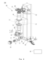
- FIG. 4 is a diagram showing a schematic diagram of the overall configuration of the imaging device 100.
- the imaging device 100 is a confocal imaging device using multiple pinholes.
- a multi-pinhole plate 40 with multiple pinholes is disposed in the optical path of the illumination light L1. This allows the illumination light L1 to form multiple focal points on the sample 20.
- the same configuration as that in FIG. 1 will be omitted as appropriate.
- the configuration of the lens system 30 is the same as that in FIG. 1.
- the light source 10 generates illumination light L1.
- the light source 10 is a high-brightness LED.
- the light source 10 is not limited to an LED, and may be a laser light source or the like.
- the illumination light L1 from the light source 10 is incident on the homogenizing optical system 11.
- the homogenizing optical system 11 has a fly-eye lens pair and a lens, and homogenizes the spatial distribution of the illumination light L1.
- the homogenizing optical system 11 homogenizes the spatial distribution of the illumination light L1 in the multi-pinhole plate 40 described below.
- the illumination light L1 from the homogenizing optical system 11 is incident on the mirror 17.
- the mirror 17 reflects the illumination light L1 incident from the side upward.
- the illumination light L1 reflected by the mirror 17 is incident on the dichroic mirror 15.
- the dichroic mirror 15 is a beam splitter that splits the illumination light L1 and the fluorescence according to the wavelength.
- the dichroic mirror 15 has wavelength characteristics that allow the illumination light L1 to pass through.
- the illumination light L1 that passes through the dichroic mirror 15 is incident on the multi-pinhole plate 40.
- the multi-pinhole plate 40 has multiple pinholes 40a formed therein.
- the multi-pinhole plate 40 is disposed at a position conjugate with the sample 20. Therefore, the illumination light L1 that passes through the multiple pinholes 40a forms multiple foci on the sample 20.
- the imaging device 100 uses the multi-pinhole to form multiple foci on the sample 20.
- the diameter of each pinhole 40a is 6 ⁇ m.
- the diameter of the pinhole 40a is not limited to the above value. As a result of using pinholes 40a of various diameters, it is preferable to set the diameter of the pinhole 40a to 15 ⁇ m or less, and more preferably to 12 ⁇ m or less.
- the multiple pinholes 40a are also arranged in a spiral shape with intervals between them.
- the optimal pinhole spacing depends on the brightness and distribution of the fluorescent molecules in the sample.
- the multiple pinholes 40a are arranged in an array with a pitch of 24 ⁇ m.
- the pitch of the pinholes 40a is not limited to the above value.
- the pitch of the pinholes 40a is preferably 50 ⁇ m or less, and more preferably 30 ⁇ m or less.
- the multi-pinhole plate 40 is a disk (rotating disk) rotated by the driving mechanism 41.
- the driving mechanism 41 includes a rotary motor that rotates the multi-pinhole plate 40.
- the multi-pinhole plate 40 is a circular rotating disk, the center of which is the rotation axis of the driving mechanism 41.
- the rotation axis is parallel to the optical axis and is disposed offset from the optical axis in the xy plane.
- the driving mechanism 41 drives the multi-pinhole plate 40 to rotate at a constant rotation speed. This changes the position of the multi-focal point on the sample 20. Therefore, the sample 20 can be scanned by the illumination light L1, and an image of the sample 20 can be captured.
- the multi-pinhole plate 40 may be mounted on a z ⁇ three-axis driving stage.
- the illumination light L1 that passes through the multi-pinhole plate 40 is incident on the imaging lens 31.
- the NA of the imaging lens 31 is 0.125.
- the illumination light L1 from the imaging lens 31 is incident on the objective lens 16.
- the objective lens 16 focuses the illumination light L1 on the sample 20.
- the sample 20 is, for example, cells held in a cell incubator 21.
- the cell incubator 21 is mounted on a sample stage 22.
- the sample stage 22 has a drive mechanism that changes the position of the sample 20.
- the sample stage 22 is a five-axis drive stage of xyz ⁇ .
- the fluorescent substance in the sample 20 When the fluorescent substance in the sample 20 is excited by the illumination light L1, fluorescence is generated.
- the fluorescence from the sample 20 becomes signal light L2 and enters the objective lens 16.
- the NA of the objective lens 16 is 0.25.
- the signal light L2 refracted by the objective lens 16 enters the imaging lens 31.
- the multi-pinhole plate 40 is disposed on the image plane of the imaging lens 31. Therefore, the imaging lens 31 forms an image of the sample 20 on the multi-pinhole plate 40.
- the signal light that passes through the pinhole 40a of the multi-pinhole plate 40 enters the dichroic mirror 15.
- the dichroic mirror 15 is disposed directly below the multi-pinhole plate 40.
- the dichroic mirror 15 splits the optical path of the illumination light L1 and the optical path of the signal light L2 based on the difference in wavelength.
- the signal light L2 is reflected by the dichroic mirror 15 toward the relay lens 34.
- the signal light L2 reflected by the dichroic mirror 15 is incident on the filter 33.
- the filter 33 is a wavelength filter that transmits light of the fluorescent wavelength and blocks light of the excitation light wavelength.
- the filter 33 is, for example, a 2-inch bandpass fluorescence filter (#86-992, Edmund Optics).
- the dichroic mirror 15 may be a short-pass dichroic mirror having a cutoff wavelength between the illumination light L1 and the signal light L2.
- a short-pass dichroic mirror By using a short-pass dichroic mirror, image distortion caused by the signal light can be suppressed.
- the dichroic mirror 15 is made a short-pass type so that the signal light reflected by the dichroic mirror 15 is detected. This makes it possible to suppress image distortion.
- the signal light L2 transmitted through the filter 33 enters the relay lens 34.
- the relay lens 34 is a telecentric lens, and forms a confocal image of the sample 20 on the camera 32.
- the relay lens 34 is, for example, a telecentric macro lens (LSTL10H-F, Myutron) with a magnification of 1x. If the relay lens 34 has a magnification of 1x and the lens system 30 has a magnification of 2x, the total magnification is 2x. By replacing the relay lens 34 with a lens (LSTL20H-F, Myutron) with a magnification of 2x, the total magnification can be switched from 2x to 4x.
- the sample 20 can be imaged at a low magnification of 2x or less, or 4x or less. Furthermore, if the magnification of the lens system 30 is 4x, the sample 20 can be imaged at a total magnification of 4x or less, or 8x or less.
- the camera 32 is an imaging device such as a CMOS sensor, and has a plurality of pixels arranged in an array. For example, a 150 million pixel camera or a 250 million pixel camera can be used as the camera 32.
- the camera 32 outputs detection data detected by each pixel to the processing device 35. Since the imaging device 100 uses a multifocal confocal optical system, pixels at positions corresponding to the multifocal points receive the signal light L2. Then, each pixel of the camera 32 outputs detection data indicating the brightness value of the light detected by the signal light L2.
- the camera 32 While the driving mechanism 41 is driving the multi-pinhole plate 40, the camera 32 detects the signal light L2.
- the processing device 35 generates a confocal image based on the detection data from the camera 32.
- the processing device 35 stores the imaging data of the captured image of the sample 20 in a memory or the like. In this way, the processing device 35 generates a confocal image of the sample 20 based on the signal light detected by the camera 32 when the multi-pinhole plate 40 is driven.
- the processing device 35 may control the driving of the driving mechanism 41 and the sample stage 22.
- the imaging device 100 can capture a confocal image of the sample 20 using the multi-pinhole plate 40.
- the multi-pinhole plate 40 is disposed at a position conjugate with the sample 20.
- the imaging lens 31 forms a primary image of the sample 20 on the multi-pinhole plate 40.
- the multi-pinhole plate 40 is disposed at a position conjugate with the light receiving surface of the camera 32.
- the processing device 35 can generate a confocal image (tomographic image) of the sample 20 on the focal plane based on the detection data of each pixel.
- the sample stage 22 moves the sample 20 in the z direction
- the focal position of the illumination light L1 in the sample 20 changes in the z direction. This allows the imaging device 100 to capture multiple tomographic images (z-stack data).
- the multi-pinhole plate 40 is installed so as to be in a conjugate imaging relationship with the sample 20. This allows a confocal optical system to be constructed, improving the resolution in the z direction. The use of the multi-pinhole plate 40 allows imaging in a short time.
- the imaging device 100 does not include a microlens array for forming multiple foci on the sample 20. In other words, the imaging device 100 forms multiple foci on the sample 20 without using a microlens array.
- One method of increasing the NA of the microlens array is to make the microlenses larger. However, doing so would reduce the number of microlenses, i.e., the number of focal points transferred onto the sample, making it impossible to illuminate a wide field of view uniformly.
- a microlens is not used to form multiple foci, and only a pinhole array is used.
- This method is more classical than the method using a microlens, and since there is no microlens, the light utilization efficiency is inferior, but the above problems can be avoided. For this reason, it is suitable for imaging devices with high NA and low magnification.
- Confocal systems using microlens array disks are commercially available, but the diameter of the pinhole array disks used in general microscopes is several tens of ⁇ m, and the pinhole spacing is several hundred ⁇ m.
- Yokogawa Electric's CSU-X has a pinhole diameter of 50 ⁇ m and a pinhole spacing of 250 ⁇ m.
- the pinhole size is set to 6 ⁇ m.
- a 6 ⁇ m pinhole is reduced and projected to 3 ⁇ m in the sample.
- This size is slightly larger than the diameter of the Airy disc at the excitation light wavelength (up to 470 nm) of GFP (Green Fluorescent Protein) and the like and the excitation light wavelength (up to 570 nm) of RFP (Red Fluorescent Protein) and the like.
- the PSF of the optical system of the excitation light (the outward path from the pinhole 40a to the sample) must take into account the spread due to diffraction at the pinhole 40a.
- the PSF of the optical system of the signal light (the return path from the sample to the pinhole) is the convolution integral of the PSF of the point light source and the pinhole.
- the total PSF of the imaging device 100 is the product of the PSFs of the outward and return paths. Furthermore, because the homogenizing optical system 11 distributes the excitation light uniformly in the multi-pinhole plate 40, the excitation light becomes multiple plane waves with different angles of incidence on the pinhole 40a.
- the optimal pinhole spacing also depends on the brightness and distribution of the fluorescent molecules in the sample. In this embodiment, the pinhole spacing is 24 ⁇ m. For example, it is preferable to set the pinhole spacing to 50 ⁇ m or less, and more preferably to 30 ⁇ m or less.
- the multi-pinhole plate 40 is disposed directly below the imaging lens 31, which is an imaging lens. In other words, the multi-pinhole plate 40 is disposed immediately after the imaging lens 31. In this manner, the imaging lens 31 and the multi-pinhole plate 40 can be disposed close to each other.
- the optical system that detects the signal light L2 from the sample 20 the objective lens 16, the imaging lens 31, the multi-pinhole plate 40, and the dichroic mirror 15 are disposed in this order. Then, the signal light L2 branched by the dichroic mirror 15 is incident on the camera 32 via the relay lens 34, which is a telecentric lens. In other words, the relay lens 34 forms an image of the multi-pinhole plate 40 on the camera 32. With this configuration, the sample 20 can be appropriately imaged in a wide field of view.
- the magnification of the relay lens 34 is 1x or 2x.
- the projection size of the pinhole 40a on the camera 32 is 15 ⁇ m or less.
- the projection size of the pinhole 40a on the camera 32 is 30 ⁇ m or less. In this way, a sufficient amount of light can be detected at each pixel, and the sample 20 can be properly imaged with high spatial resolution.
- FIG. 6 is a diagram showing the imaging results of the imaging device 100.
- a sample in which 0.5 ⁇ m fluorescent beads are three-dimensionally dispersed in an agarose gel is used.
- an image of an area of 292 ⁇ m ⁇ 202 ⁇ m, which corresponds to 1/50 2 of the entire FOV is shown.
- the upper row shows an image captured without the multi-pinhole plate 40.
- the middle row shows an image captured with the multi-pinhole plate 40.
- the lower row shows the line profiles of these images.
- the imaging device 100 can capture images appropriately in a wide field of view.
- Fig. 7 shows the evaluation results of the point spread function (PSF).
- the focal position is scanned in the z direction, and the processing device 35 captures two-dimensional images at each z position. This makes it possible to obtain multiple tomographic images, i.e., z-stack data.
- the imaging device 100 captures multiple tomographic images by changing the focal position in the z direction.
- the processing device 35 removes background light components by performing image processing on the image data acquired by the camera 32. Specifically, the processing device 35 separates signals from the focal plane and signals from outside the focal plane through calculation.
- the image before the background light components are removed is the captured image.
- the captured image is a superposition of images of objects within the focal plane and images of objects outside the focal plane. It is assumed that the imaging data of the captured image has a high spatial frequency for the fluorescent image from within the focal plane and a low spatial frequency for the fluorescent image from outside the focal plane.
- the processing device 35 estimates the contribution from outside the focal plane as a baseline by iterative low-pass filtering. An image from within the focal plane is obtained by subtracting the baseline image from the captured image.
- the baseline image is two-dimensional data indicating the background light components from outside the focal plane.
- the processing device 35 performs this calculation for each layer of the z-stack and reconstructs it into a three-dimensional image.
- Figure 8 shows an image in which background light components have been removed by sectioning calculation.
- Figure 8 shows an image of the cavity and chamber structure of a myocardial organoid.
- This organoid is a 3D organoid that has been widely studied in developmental biology and regenerative medicine in recent years, and is known as a model of human myocardial tissue development. Large-area organoids are created across the entire FOV and chemically fixed. Troponin was immunostained, and nuclei were stained with Hoechst.
- the maximum height of the organoids is approximately 150 ⁇ m.
- Z-stack data was obtained by repeatedly scanning the three-dimensional area containing the organoids in the z direction in 4 ⁇ m steps. Images A and B in Figure 8 are images of the organoids across the entire FOV.
- Image A is the captured image before computational sectioning
- Image B is the processed image after computational sectioning.
- Both images A and B are maximum intensity projection images of the z-stack. In both z-planes, strong background light was superimposed before computational processing, but after computational processing, the three-dimensional distribution of nuclei was clearly visualized.
- Image C is an image of the local area indicated by the dashed frame in image A
- image D is an image of the local area indicated by the white frame in image B.
- Images C and D show cross-sectional images when the z position is changed at 40 ⁇ m intervals.
- the focal plane components on the baseline can be extracted using the above calculation.
- This method requires that the spatial frequency of the fluorescent image within the focal plane is clearly higher than the spatial frequency of the image outside the focal plane. In actual cell imaging, this method is effective when fluorescent molecules are localized within the cell, such as in the nucleus, or when they have a filament-like structure. On the other hand, care must be taken with distributions that have spatially uniform intensity, as this can produce results that emphasize the areas near the edges.
- the processing device 35 estimates the background light component using a low-pass filter. Specifically, the processing device 35 removes the background light component by iteratively calculating the filtering process using a low-pass filter as follows:
- the image data of the image captured by the camera 32 is f 0 (x, y).
- the image data f 0 (x, y) is two-dimensional image data, and a luminance value is set for each x and y coordinate.
- the processing device 35 calculates the curved surface data L 0 (x, y) of a smooth curved surface by applying a low-pass filter to the image data f 0 (x, y).
- the curved surface data L 0 (x, y) is a low-frequency component contained in the image data f 0 (x, y), and specifically indicates a background light component. In other words, the processing device 35 extracts the low-frequency component of the image data f 0 (x, y) as an orientation component.
- the processing device 35 takes the smaller value of f 0 (x, y) and L 0 (x, y) at each coordinate, and sets it as f 1 (x, y).
- the processing device 35 obtains f 2 (x, y) by performing the same processing on f 1 (x, y). That is, the processing device 35 applies a low-pass filter to f 1 (x, y) to generate L 1 (x, y).
- the processing device 35 takes the smaller value of f 1 (x, y) and L 1 (x, y) at each coordinate, and sets it as f 2 (x, y).
- the processing device 35 performs iterative calculations using the following formula (1).
- min(a, b) is a function that returns the smaller value of a and b.
- j is an integer equal to or greater than 1.
- the processing device 35 increments j from 1 by the iterative calculation of formula (1).
- Image data L j-1 (x, y) is image data obtained by applying a low-pass filter to image data f j-1 (x, y).
- f j (x, y) asymptotically approaches the baseline of image data f 0 (x, y).
- f j (x, y) is image data that indicates a background light component.
- the processing device 35 repeats the iterative calculation of formula (1) until the standard deviation Var of the difference between f j (x, y) and L j (x, y) reaches a preset value ⁇ .
- the processing device 35 calculates image data L j (x, y) indicating the background light component by performing processing using a low-pass filter on f j (x, y) when the standard deviation converges to a preset value ⁇ .
- the processing device 35 sets the image data L j (x, y) as baseline data.
- the image data L j ( x, y) converges to the baseline of the image data f 0 (x, y) of the captured image.
- the processing device 35 obtains a confocal image from which the background light component has been removed by subtracting the baseline image data L j (x, y) from the image data f 0 (x, y) of the captured image.
- the processing device 35 may perform processing using a convolution filter such as a moving average method, or a low-pass filter in Fourier space using FFT (Fast Fourier Transform). Note that when the number of pixels is very large, the processing time becomes long, so the processing device 35 uses an infinite impulse response (IIR) filter to increase speed.
- a convolution filter such as a moving average method, or a low-pass filter in Fourier space using FFT (Fast Fourier Transform). Note that when the number of pixels is very large, the processing time becomes long, so the processing device 35 uses an infinite impulse response (IIR) filter to increase speed.
- IIR infinite impulse response
- the processing device 35 applies a one-dimensional IIR filter sequentially in two directions (x, y) as a calculation method for a two-dimensional low-pass filter. For example, a one-dimensional infinite impulse response filter in the x direction may be applied first, and then a one-dimensional impulse response filter in the y direction, or the filters may be applied in the reverse order.
- the processing device 35 can use, for example, a Butterworth filter as the IIR low-pass filter.
- a part or all of the processing in the processing device 35 may be executed by a computer program.
- the above-mentioned program can be stored and supplied to a computer using various types of non-transitory computer readable medium.
- Non-transitory computer readable medium includes various types of tangible storage medium.
- non-transitory computer-readable media examples include magnetic recording media (e.g., flexible disks, magnetic tapes, hard disk drives), magneto-optical recording media (e.g., magneto-optical disks), CD-ROMs (Read Only Memory), CD-Rs, CD-R/Ws, and semiconductor memories (e.g., mask ROMs, PROMs (Programmable ROMs), EPROMs (Erasable PROMs), flash ROMs, and RAMs (Random Access Memory)).
- the program may also be supplied to the computer by various types of transient computer-readable media. Examples of transient computer-readable media include electrical signals, optical signals, and electromagnetic waves.
- the transient computer-readable medium may supply the program to the computer via a wired communication path such as an electric wire or optical fiber, or via a wireless communication path.
- Fig. 9 is an image showing the processing result obtained by the computational sectioning.
- image data f0 (x,y) of the captured image indicates image data captured by the camera 32.
- estimated baseline image data Lj (x,y) and image data in the focal plane (in focus) are shown to the right of the image data f0 (x,y) of the captured image.
- the processing device 35 calculates the image data in the focal plane by subtracting the image data fj (x,y) from the image data f0 (x,y).
- the processing device 35 separates the image data of the captured image into baseline image data and image data within the focal plane. Below the image data of the captured image (raw data), line profiles of the image data of the captured image, baseline image data, and image data within the focal plane are shown. In this way, background light components from outside the focal plane can be removed by computational sectioning.
- the sample 20 is a 1.5 mm thick section of the coronal plane of a mouse brain. This section was placed on a transparent glass container 25.
- the mouse brain was chemically cleared using the tissue clearing reagent CUBIC, and the cell nuclei were specifically stained with SYTOX-Green.
- a relay lens 34 with a magnification of 1x was used to cover the entire coronal plane, and the sample 20 was imaged at an overall magnification of 2x.
- the exposure time for one z-plane was 1 second, and the sample stage 22 scanned the 1.5 mm thick sample 20 in the z-direction at 4 ⁇ m steps.
- the imaging device 100 then acquired z-stack data for 378 layers.
- the imaging device 100 acquired images of the sample 20 using both optical and computational sectioning.
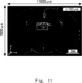
- Image C in Figure 12 shows an enlarged view of the xy plane (coronal plane) in the dashed rectangular area in Figure 11, as well as xz (transverse plane) and yz (sagittal plane) cross sections.
- the xz and yz cross sections clearly show that tomographic images in the z direction have been obtained.
- Image C in Figure 12 shows processed data after computational sectioning.
- image D in Figure 12 is a three-dimensional representation before computational sectioning processing (raw data obtained by optical sectioning). Plane-selective imaging is possible with optical sectioning alone, but strong background light is superimposed. In particular, in areas with high cell density, strong background light is superimposed on the images of the areas before and after it. It has been confirmed that by removing this background light through computational processing, a clear image with high contrast can be obtained, as shown in image C in Figure 12.
- Image E in Figure 12 compares three z-plane images in an xy region that includes the choroid plexus region.
- Image F in Figure 12 is an isosurface display of nuclei within a 200 ⁇ m x 200 ⁇ m x 200 ⁇ m cube in the choroid plexus region. Due to the low spatial resolution in the z direction, each nucleus has a long and narrow shape in the z direction, but in three-dimensional space it can be seen that they are spatially separated from the surrounding nuclei. In addition, the three-dimensional structures of the hippocampal dentate gyrus granule cells and medial habenula, which are known to be related to memory formation and depression, are also clearly visualized (Image C in Figure 12).
- the imaging device 100 uses a confocal optical system, so background light can be removed even when imaging with a wide field of view.
- the resolution in the optical axis direction can be improved to 15 ⁇ m.
- the sample 20 can be imaged with a wide field of view with a total magnification of 4 times or less.
- the confocal imaging method includes the steps of generating illumination light L1 for illuminating the sample 20, making the illumination light L1 incident on a multi-pinhole plate 40 arranged at a position conjugate with the sample 20, focusing the illumination light L1 transmitted through the multiple pinholes of the multi-pinhole plate on the sample 20 by the objective lens 16, making the signal light from the sample 20 incident on the objective lens 16, imaging the signal light from the sample 20 on the multi-pinhole plate 40 by an imaging lens arranged between the objective lens 16 and the multi-pinhole plate, splitting the signal light that has passed through the multiple pinholes 40a from the illumination light heading toward the multi-pinhole plate by a beam splitter, imaging the signal light split by the beam splitter on an imaging device by a telecentric lens, driving the multi-pinhole plate to change the incident position of the illumination light on the sample, and imaging the sample by the signal light detected by the imaging device when the multi-pinhole plate is driven.
Landscapes
- Physics & Mathematics (AREA)
- Health & Medical Sciences (AREA)
- Analytical Chemistry (AREA)
- General Physics & Mathematics (AREA)
- Chemical & Material Sciences (AREA)
- Engineering & Computer Science (AREA)
- Multimedia (AREA)
- Signal Processing (AREA)
- Optics & Photonics (AREA)
- Nuclear Medicine, Radiotherapy & Molecular Imaging (AREA)
- Life Sciences & Earth Sciences (AREA)
- Biochemistry (AREA)
- General Health & Medical Sciences (AREA)
- Immunology (AREA)
- Pathology (AREA)
- Microscoopes, Condenser (AREA)
Priority Applications (1)
| Application Number | Priority Date | Filing Date | Title |
|---|---|---|---|
| JP2025519434A JPWO2024232351A1 (https=) | 2023-05-09 | 2024-05-07 |
Applications Claiming Priority (2)
| Application Number | Priority Date | Filing Date | Title |
|---|---|---|---|
| JP2023077341 | 2023-05-09 | ||
| JP2023-077341 | 2023-05-09 |
Publications (1)
| Publication Number | Publication Date |
|---|---|
| WO2024232351A1 true WO2024232351A1 (ja) | 2024-11-14 |
Family
ID=93429993
Family Applications (1)
| Application Number | Title | Priority Date | Filing Date |
|---|---|---|---|
| PCT/JP2024/016941 Ceased WO2024232351A1 (ja) | 2023-05-09 | 2024-05-07 | 共焦点イメージング装置、及び共焦点イメージング方法 |
Country Status (2)
| Country | Link |
|---|---|
| JP (1) | JPWO2024232351A1 (https=) |
| WO (1) | WO2024232351A1 (https=) |
Citations (5)
| Publication number | Priority date | Publication date | Assignee | Title |
|---|---|---|---|---|
| WO2002023248A1 (fr) * | 2000-09-11 | 2002-03-21 | Olympus Optical Co., Ltd. | Microscope confocal et procede de mesure de hauteur utilisant ledit microscope |
| JP2010097768A (ja) * | 2008-10-15 | 2010-04-30 | Topcon Corp | 複合型観察装置 |
| JP2010181688A (ja) * | 2009-02-06 | 2010-08-19 | Yokogawa Electric Corp | 共焦点顕微鏡装置 |
| JP2018527607A (ja) * | 2015-07-17 | 2018-09-20 | ザ トラスティース オブ コロンビア ユニバーシティ イン ザ シティ オブ ニューヨーク | 3次元イメージングのためのシステムおよび方法 |
| JP2023003158A (ja) * | 2021-06-23 | 2023-01-11 | 国立大学法人大阪大学 | 蛍光イメージング装置 |
-
2024
- 2024-05-07 JP JP2025519434A patent/JPWO2024232351A1/ja active Pending
- 2024-05-07 WO PCT/JP2024/016941 patent/WO2024232351A1/ja not_active Ceased
Patent Citations (5)
| Publication number | Priority date | Publication date | Assignee | Title |
|---|---|---|---|---|
| WO2002023248A1 (fr) * | 2000-09-11 | 2002-03-21 | Olympus Optical Co., Ltd. | Microscope confocal et procede de mesure de hauteur utilisant ledit microscope |
| JP2010097768A (ja) * | 2008-10-15 | 2010-04-30 | Topcon Corp | 複合型観察装置 |
| JP2010181688A (ja) * | 2009-02-06 | 2010-08-19 | Yokogawa Electric Corp | 共焦点顕微鏡装置 |
| JP2018527607A (ja) * | 2015-07-17 | 2018-09-20 | ザ トラスティース オブ コロンビア ユニバーシティ イン ザ シティ オブ ニューヨーク | 3次元イメージングのためのシステムおよび方法 |
| JP2023003158A (ja) * | 2021-06-23 | 2023-01-11 | 国立大学法人大阪大学 | 蛍光イメージング装置 |
Also Published As
| Publication number | Publication date |
|---|---|
| JPWO2024232351A1 (https=) | 2024-11-14 |
Similar Documents
| Publication | Publication Date | Title |
|---|---|---|
| US10989661B2 (en) | Uniform and scalable light-sheets generated by extended focusing | |
| Ji et al. | Technologies for imaging neural activity in large volumes | |
| CN104204898B (zh) | 光片光学系统 | |
| CN107167929B (zh) | 基于dmd的双模式光学超分辨显微成像装置及方法 | |
| CN109001898B (zh) | 一种小型化的多角度三维超分辨光片荧光显微镜 | |
| JP5999121B2 (ja) | 共焦点光スキャナ | |
| JP6996048B2 (ja) | 広視野高分解能顕微鏡 | |
| CN111307772B (zh) | 基于微镜阵列的单物镜光片荧光显微成像装置及方法 | |
| US9581798B2 (en) | Light sheet-based imaging device with extended depth of field | |
| US10401605B2 (en) | Structured illumination in inverted light sheet microscopy | |
| CN110836877A (zh) | 一种基于液晶变焦透镜的光切片显微成像方法和装置 | |
| CN106842529A (zh) | 快速三维显微成像系统 | |
| CN111273433A (zh) | 一种高速大视场数字扫描光片显微成像系统 | |
| JP2018520388A (ja) | 複数の対象面を同時にイメージングする光シート顕微鏡 | |
| US20190170646A1 (en) | Light-sheet microscope with parallelized 3d image acquisition | |
| US20150131148A1 (en) | Spinning disk confocal using paired microlens disks | |
| CN107228846B (zh) | 基于离轴光束焦面共轭的荧光成像光切片方法和装置 | |
| JP6090607B2 (ja) | 共焦点スキャナ、共焦点顕微鏡 | |
| Qu et al. | Recent progress in multifocal multiphoton microscopy | |
| WO2019178090A1 (en) | Light disc microscopy for fluorescence microscopes | |
| Murray | Methods for imaging thick specimens: confocal microscopy, deconvolution, and structured illumination | |
| US10211024B1 (en) | System and method for axial scanning based on static phase masks | |
| CN108982455B (zh) | 一种多焦点光切片荧光显微成像方法和装置 | |
| JP2025165881A (ja) | 曲面ライトシート顕微鏡結像装置及び方法 | |
| CN117330542A (zh) | 高对比度各向同性高分辨荧光显微成像方法及成像系统 |
Legal Events
| Date | Code | Title | Description |
|---|---|---|---|
| 121 | Ep: the epo has been informed by wipo that ep was designated in this application |
Ref document number: 24803462 Country of ref document: EP Kind code of ref document: A1 |
|
| ENP | Entry into the national phase |
Ref document number: 2025519434 Country of ref document: JP Kind code of ref document: A |
|
| WWE | Wipo information: entry into national phase |
Ref document number: 2025519434 Country of ref document: JP |
|
| NENP | Non-entry into the national phase |
Ref country code: DE |