WO2024232159A1 - 積層光学フィルムの製造方法 - Google Patents
積層光学フィルムの製造方法 Download PDFInfo
- Publication number
- WO2024232159A1 WO2024232159A1 PCT/JP2024/009464 JP2024009464W WO2024232159A1 WO 2024232159 A1 WO2024232159 A1 WO 2024232159A1 JP 2024009464 W JP2024009464 W JP 2024009464W WO 2024232159 A1 WO2024232159 A1 WO 2024232159A1
- Authority
- WO
- WIPO (PCT)
- Prior art keywords
- optical film
- meth
- group
- acrylate
- adhesive composition
- Prior art date
- Legal status (The legal status is an assumption and is not a legal conclusion. Google has not performed a legal analysis and makes no representation as to the accuracy of the status listed.)
- Ceased
Links
Classifications
-
- B—PERFORMING OPERATIONS; TRANSPORTING
- B32—LAYERED PRODUCTS
- B32B—LAYERED PRODUCTS, i.e. PRODUCTS BUILT-UP OF STRATA OF FLAT OR NON-FLAT, e.g. CELLULAR OR HONEYCOMB, FORM
- B32B27/00—Layered products comprising a layer of synthetic resin
-
- B—PERFORMING OPERATIONS; TRANSPORTING
- B32—LAYERED PRODUCTS
- B32B—LAYERED PRODUCTS, i.e. PRODUCTS BUILT-UP OF STRATA OF FLAT OR NON-FLAT, e.g. CELLULAR OR HONEYCOMB, FORM
- B32B37/00—Methods or apparatus for laminating, e.g. by curing or by ultrasonic bonding
- B32B37/12—Methods or apparatus for laminating, e.g. by curing or by ultrasonic bonding characterised by using adhesives
-
- B—PERFORMING OPERATIONS; TRANSPORTING
- B32—LAYERED PRODUCTS
- B32B—LAYERED PRODUCTS, i.e. PRODUCTS BUILT-UP OF STRATA OF FLAT OR NON-FLAT, e.g. CELLULAR OR HONEYCOMB, FORM
- B32B7/00—Layered products characterised by the relation between layers; Layered products characterised by the relative orientation of features between layers, or by the relative values of a measurable parameter between layers, i.e. products comprising layers having different physical, chemical or physicochemical properties; Layered products characterised by the interconnection of layers
- B32B7/02—Physical, chemical or physicochemical properties
- B32B7/023—Optical properties
-
- C—CHEMISTRY; METALLURGY
- C09—DYES; PAINTS; POLISHES; NATURAL RESINS; ADHESIVES; COMPOSITIONS NOT OTHERWISE PROVIDED FOR; APPLICATIONS OF MATERIALS NOT OTHERWISE PROVIDED FOR
- C09D—COATING COMPOSITIONS, e.g. PAINTS, VARNISHES OR LACQUERS; FILLING PASTES; CHEMICAL PAINT OR INK REMOVERS; INKS; CORRECTING FLUIDS; WOODSTAINS; PASTES OR SOLIDS FOR COLOURING OR PRINTING; USE OF MATERIALS THEREFOR
- C09D201/00—Coating compositions based on unspecified macromolecular compounds
-
- C—CHEMISTRY; METALLURGY
- C09—DYES; PAINTS; POLISHES; NATURAL RESINS; ADHESIVES; COMPOSITIONS NOT OTHERWISE PROVIDED FOR; APPLICATIONS OF MATERIALS NOT OTHERWISE PROVIDED FOR
- C09D—COATING COMPOSITIONS, e.g. PAINTS, VARNISHES OR LACQUERS; FILLING PASTES; CHEMICAL PAINT OR INK REMOVERS; INKS; CORRECTING FLUIDS; WOODSTAINS; PASTES OR SOLIDS FOR COLOURING OR PRINTING; USE OF MATERIALS THEREFOR
- C09D4/00—Coating compositions, e.g. paints, varnishes or lacquers, based on organic non-macromolecular compounds having at least one polymerisable carbon-to-carbon unsaturated bond ; Coating compositions, based on monomers of macromolecular compounds of groups C09D183/00 - C09D183/16
-
- C—CHEMISTRY; METALLURGY
- C09—DYES; PAINTS; POLISHES; NATURAL RESINS; ADHESIVES; COMPOSITIONS NOT OTHERWISE PROVIDED FOR; APPLICATIONS OF MATERIALS NOT OTHERWISE PROVIDED FOR
- C09D—COATING COMPOSITIONS, e.g. PAINTS, VARNISHES OR LACQUERS; FILLING PASTES; CHEMICAL PAINT OR INK REMOVERS; INKS; CORRECTING FLUIDS; WOODSTAINS; PASTES OR SOLIDS FOR COLOURING OR PRINTING; USE OF MATERIALS THEREFOR
- C09D5/00—Coating compositions, e.g. paints, varnishes or lacquers, characterised by their physical nature or the effects produced; Filling pastes
-
- C—CHEMISTRY; METALLURGY
- C09—DYES; PAINTS; POLISHES; NATURAL RESINS; ADHESIVES; COMPOSITIONS NOT OTHERWISE PROVIDED FOR; APPLICATIONS OF MATERIALS NOT OTHERWISE PROVIDED FOR
- C09D—COATING COMPOSITIONS, e.g. PAINTS, VARNISHES OR LACQUERS; FILLING PASTES; CHEMICAL PAINT OR INK REMOVERS; INKS; CORRECTING FLUIDS; WOODSTAINS; PASTES OR SOLIDS FOR COLOURING OR PRINTING; USE OF MATERIALS THEREFOR
- C09D7/00—Features of coating compositions, not provided for in group C09D5/00; Processes for incorporating ingredients in coating compositions
- C09D7/40—Additives
- C09D7/60—Additives non-macromolecular
- C09D7/63—Additives non-macromolecular organic
-
- C—CHEMISTRY; METALLURGY
- C09—DYES; PAINTS; POLISHES; NATURAL RESINS; ADHESIVES; COMPOSITIONS NOT OTHERWISE PROVIDED FOR; APPLICATIONS OF MATERIALS NOT OTHERWISE PROVIDED FOR
- C09J—ADHESIVES; NON-MECHANICAL ASPECTS OF ADHESIVE PROCESSES IN GENERAL; ADHESIVE PROCESSES NOT PROVIDED FOR ELSEWHERE; USE OF MATERIALS AS ADHESIVES
- C09J133/00—Adhesives based on homopolymers or copolymers of compounds having one or more unsaturated aliphatic radicals, each having only one carbon-to-carbon double bond, and at least one being terminated by only one carboxyl radical, or of salts, anhydrides, esters, amides, imides, or nitriles thereof; Adhesives based on derivatives of such polymers
- C09J133/24—Homopolymers or copolymers of amides or imides
- C09J133/26—Homopolymers or copolymers of acrylamide or methacrylamide
-
- C—CHEMISTRY; METALLURGY
- C09—DYES; PAINTS; POLISHES; NATURAL RESINS; ADHESIVES; COMPOSITIONS NOT OTHERWISE PROVIDED FOR; APPLICATIONS OF MATERIALS NOT OTHERWISE PROVIDED FOR
- C09J—ADHESIVES; NON-MECHANICAL ASPECTS OF ADHESIVE PROCESSES IN GENERAL; ADHESIVE PROCESSES NOT PROVIDED FOR ELSEWHERE; USE OF MATERIALS AS ADHESIVES
- C09J4/00—Adhesives based on organic non-macromolecular compounds having at least one polymerisable carbon-to-carbon unsaturated bond ; adhesives, based on monomers of macromolecular compounds of groups C09J183/00 - C09J183/16
-
- C—CHEMISTRY; METALLURGY
- C09—DYES; PAINTS; POLISHES; NATURAL RESINS; ADHESIVES; COMPOSITIONS NOT OTHERWISE PROVIDED FOR; APPLICATIONS OF MATERIALS NOT OTHERWISE PROVIDED FOR
- C09J—ADHESIVES; NON-MECHANICAL ASPECTS OF ADHESIVE PROCESSES IN GENERAL; ADHESIVE PROCESSES NOT PROVIDED FOR ELSEWHERE; USE OF MATERIALS AS ADHESIVES
- C09J7/00—Adhesives in the form of films or foils
- C09J7/30—Adhesives in the form of films or foils characterised by the adhesive composition
-
- G—PHYSICS
- G02—OPTICS
- G02B—OPTICAL ELEMENTS, SYSTEMS OR APPARATUS
- G02B5/00—Optical elements other than lenses
- G02B5/30—Polarising elements
Definitions
- the present invention relates to a method for producing a laminated optical film in which at least a first optical film and a second optical film are laminated via an adhesive layer.
- the laminated optical film can form image displays such as liquid crystal displays (LCDs), organic EL displays, CRTs, and PDPs.
- Liquid crystal display devices are rapidly expanding into the market for watches, mobile phones, PDAs, notebook computers, PC monitors, DVD players, TVs, and more.
- Liquid crystal display devices visualize the polarized state through the switching of liquid crystals, and polarizers are used for this display principle.
- polarizers are used for this display principle.
- polarizing films are also required to have higher transmittance, higher polarization degree, and better color reproducibility.
- polarizers are iodine-based polarizers, which have a structure in which iodine is adsorbed into polyvinyl alcohol (hereinafter also simply referred to as "PVA") and stretched, due to their high transmittance and polarization degree.
- PVA polyvinyl alcohol
- polarizing films are used in which transparent protective films are bonded to both sides of a polarizer using a so-called water-based adhesive in which a polyvinyl alcohol-based material is dissolved in water (Patent Document 1 below).
- the transparent protective film triacetyl cellulose, which has high moisture permeability, is used.
- wet lamination a drying process is required after bonding the polarizer and the transparent protective film together.
- an active energy ray-curable adhesive instead of the water-based adhesive, an active energy ray-curable adhesive has been proposed.
- a polarizing film is produced using an active energy ray-curable adhesive, a drying process is not required, and therefore the productivity of the polarizing film can be improved.
- a radical polymerization type active energy ray-curable adhesive that uses an N-substituted amide monomer as the curable component has been proposed (Patent Document 2 below).
- a method for manufacturing a polarizing film is provided on at least one surface of a polarizer with a transparent protective film via an adhesive layer, and the method includes a first coating step in which a solvent-containing easy-adhesion composition is applied to the bonding surface of the polarizer while transporting the polarizer to form a wet first coating film, a second coating step in which an adhesive composition is applied to the bonding surface of the transparent protective film while transporting the transparent protective film to form a second coating film, a first thickness measurement step in which the thickness of the wet first coating film is measured inline, a drying step in which, after the first thickness measurement step, the solvent in the wet first coating film is removed using a dryer to form a dry first coating film, and after the drying step, the dry first coating film is
- the method for producing a polarizing film includes a second thickness measurement step of in-line measuring the thickness of the first wet coating film, a dryness adjustment step of adjusting the dryness of the newly formed dry first coating film by
- Patent Document 3 a process for adjusting the degree of dryness is carried out, but in recent years, it has become necessary to increase the line speed of the laminated optical film manufacturing line, particularly from the viewpoint of improving productivity. For this reason, it has become clear that there is room for further improvement in both the materials, such as the adhesive composition and easy-adhesion composition that constitute the adhesive layer, and the process.
- the present invention was developed to solve the above problems, and aims to provide a method for manufacturing a laminated optical film that has excellent adhesion between the first optical film and the second optical film while increasing the line speed of the laminated optical film manufacturing line.
- the present invention is a method for producing a laminated optical film in which at least a first optical film and a second optical film are laminated via an adhesive layer, the method comprising: conveying the first optical film while applying a compound represented by the following general formula (1): (wherein X is a reactive group, Y is an alkylene group having 1 to 12 carbon atoms which may have a branched chain, or a phenylene group which may have a substituent, and R 1 and R and water; a second coating step of coating an adhesive composition containing at least a curable component and a polymerization initiator on the bonding surface of the second optical film while transporting the second optical film; a lamination step of laminating the first optical film and the second optical film; and an adhesion step of bonding the first optical film and the second optical film via the adhesive layer formed by irradiating the first optical film surface side or the second optical film surface side with active energy rays to
- a method (2) for producing a laminated optical film is preferred in which a drying step is not provided between the first coating step and the lamination step.
- a laminated optical film manufacturing method (3) is preferred in which the time required from the end of the first coating step to the start of the lamination step is 5 seconds or less.
- the laminated optical film manufacturing method (4) is preferred in which the first optical film is a polarizer.
- the laminated optical film manufacturing method (5) is preferred in which the second optical film is a transparent protective film.
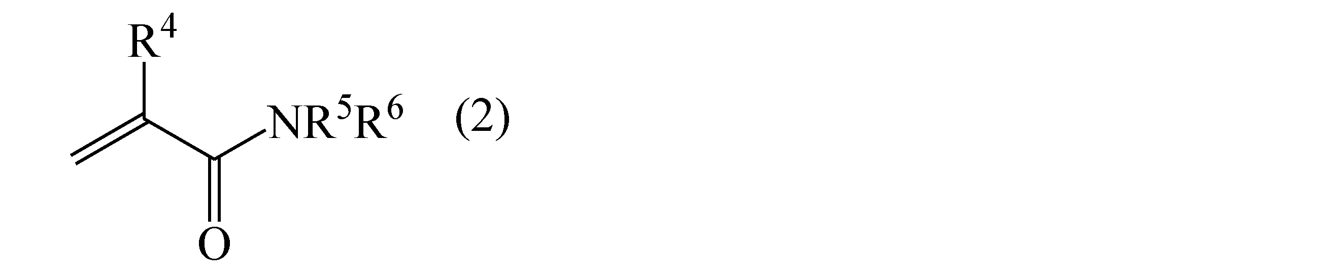
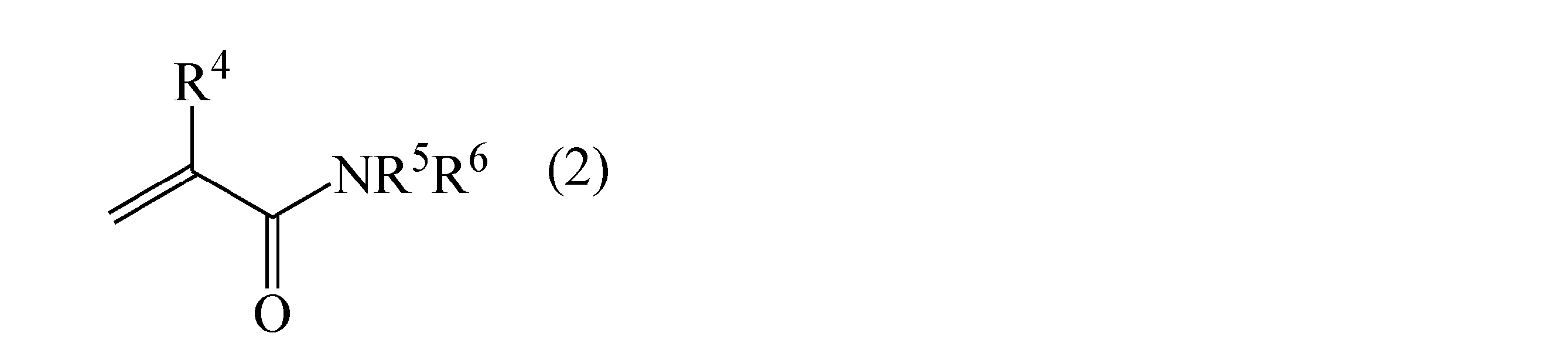
- the adhesive composition contains, as a polymerizable component, a polymerizable compound represented by the following general formula (2): (wherein R4 is a hydrogen atom or a methyl group, R5 and R6 are each independently a hydrogen atom, an alkyl group, a hydroxyalkyl group, an alkoxyalkyl group, or a cyclic ether group, and R5 and R6 may form a cyclic heterocycle), a method (6) for producing a laminated optical film containing the compound represented by the formula (1) is preferred.
- a polymerizable compound represented by the following general formula (2): wherein R4 is a hydrogen atom or a methyl group, R5 and R6 are each independently a hydrogen atom, an alkyl group, a hydroxyalkyl group, an alkoxyalkyl group, or a cyclic ether group, and R5 and R6 may form a cyclic heterocycle
- the laminated optical film manufacturing method (7) is preferred, in which the easy-adhesion composition contains a compound represented by the general formula (2).
- an easy-adhesion composition is applied to the lamination surface of a first optical film (first coating step)
- an adhesive composition is applied to the lamination surface of a second optical film (second coating step)
- the first optical film and the second optical film are laminated together so that their lamination surfaces overlap (lamination step).
- the following measures are taken in terms of materials.
- At least a specific boron-containing compound (a compound represented by general formula (1)) and water are blended into an easily adhesive composition, and the water content in the easily adhesive composition is designed to be 40 mass% or less.
- the specific boron-containing compound blended into the easy-adhesion composition contributes greatly to improving the adhesion between the first optical film and the adhesive layer, particularly improving adhesion under humid conditions.
- the line speed of the laminated optical film production line is increased, the water in the easy-adhesion composition is hardly removed, and the amount of moisture in the easy-adhesion composition increases. This reduces the relative concentration of the polymerization initiator migrating from the adhesive composition, and the boron-containing compound is unable to sufficiently react with the curable component blended into the adhesive composition, which is expected to result in a deterioration in adhesion between the first optical film and the adhesive layer.
- the water content in the easy-adhesion composition is designed to be 40% by mass or less, that is, the water content is less than that of conventional easy-adhesion compositions (above (i)), and when the film thickness of the easy-adhesion composition after the first coating step is ⁇ and the film thickness of the adhesive composition after the second coating step is ⁇ , it is designed to be ⁇ > ⁇ (above (iii)).
- the polymerization initiator blended in the adhesive composition is made to migrate easily into the easy-adhesion composition, that is, the relative concentration of the polymerization initiator migrating from the adhesive composition is increased, thereby increasing the reaction rate between the curable component blended in the adhesive composition and the boron-containing compound (above (ii)).
- the polymerization initiator blended in the adhesive composition is made to migrate easily into the easy-adhesion composition, that is, the relative concentration of the polymerization initiator migrating from the adhesive composition is increased, thereby increasing the reaction rate between the curable component blended in the adhesive composition and the boron-containing compound (above (ii)).
- the method for producing a laminated optical film according to the present invention is a method for producing a laminated optical film in which at least a first optical film and a second optical film are laminated via an adhesive layer, and the method comprises the steps of: applying a compound represented by the following general formula (1): to a bonding surface of the first optical film while transporting the first optical film; and water; a second coating step of coating an adhesive composition containing at least a curable component and a polymerization initiator on the bonding surface of the second optical film while transporting the second optical film; a bonding step of bonding the first optical film and the second optical film together; and an adhesion step of bonding the first optical film and the second optical film together via an adhesive layer formed by irradiating the first optical film surface side or the second optical film surface side with active energy rays to cure at least the adhesive composition, wherein the content of water in the easy-adhesion composition is 40 mass% or less, and when the film thickness of the easy-adhesion composition after the first coating step
- the easily adhesive composition comprises at least one compound represented by the following general formula (1): (wherein X is a reactive group, Y is an alkylene group having 1 to 12 carbon atoms which may have a branched chain, or a phenylene group which may have a substituent, and R 1 and R 2 each independently represent a hydrogen atom, an aliphatic hydrocarbon group which may have a substituent, an aryl group, or a heterocyclic group) and water.
- general formula (1) wherein X is a reactive group, Y is an alkylene group having 1 to 12 carbon atoms which may have a branched chain, or a phenylene group which may have a substituent, and R 1 and R 2 each independently represent a hydrogen atom, an aliphatic hydrocarbon group which may have a substituent, an aryl group, or a heterocyclic group
- the aliphatic hydrocarbon group includes a linear or branched alkyl group having 1 to 20 carbon atoms, which may have a substituent, a cyclic alkyl group having 3 to 20 carbon atoms, which may have a substituent, and an alkenyl group having 2 to 20 carbon atoms.
- the aryl group includes a phenyl group having 6 to 20 carbon atoms, which may have a substituent, and a naphthyl group having 10 to 20 carbon atoms, which may have a substituent
- the heterocyclic group includes, for example, a 5-membered or 6-membered ring group containing at least one hetero atom, which may have a substituent. These may be linked together to form a ring.
- R 1 and R 2 are preferably a hydrogen atom or a linear or branched alkyl group having 1 to 3 carbon atoms, and most preferably a hydrogen atom.
- X in the compound represented by general formula (1) is a reactive group, which is a functional group that can react with the curable component that constitutes the adhesive layer, and examples of such groups include a hydroxyl group, an amino group, an aldehyde group, a carboxyl group, a vinyl group, a (meth)acrylic group, a styryl group, a (meth)acrylamide group, a vinyl ether group, an epoxy group, an oxetane group, an ⁇ , ⁇ -unsaturated carbonyl group, a mercapto group, and a halogen group.
- the reactive group X is preferably at least one reactive group selected from the group consisting of vinyl group, (meth)acrylic group, styryl group, (meth)acrylamide group, vinyl ether group, epoxy group, oxetane group and mercapto group
- the reactive group X is preferably at least one reactive group selected from the group consisting of (meth)acrylic group, styryl group and (meth)acrylamide group, and when the compound represented by general formula (1) has a (meth)acrylamide group, it is more preferable because it has high reactivity and increases the copolymerization rate with the curable component in the adhesive layer.
- the reactive group X preferably has at least one functional group selected from a hydroxyl group, an amino group, an aldehyde, a carboxyl group, a vinyl ether group, an epoxy group, an oxetane group, and a mercapto group.
- the reactive group X has an epoxy group
- the reactive group X has a vinyl ether group this is preferred because the curability of the curable adhesive composition is excellent.
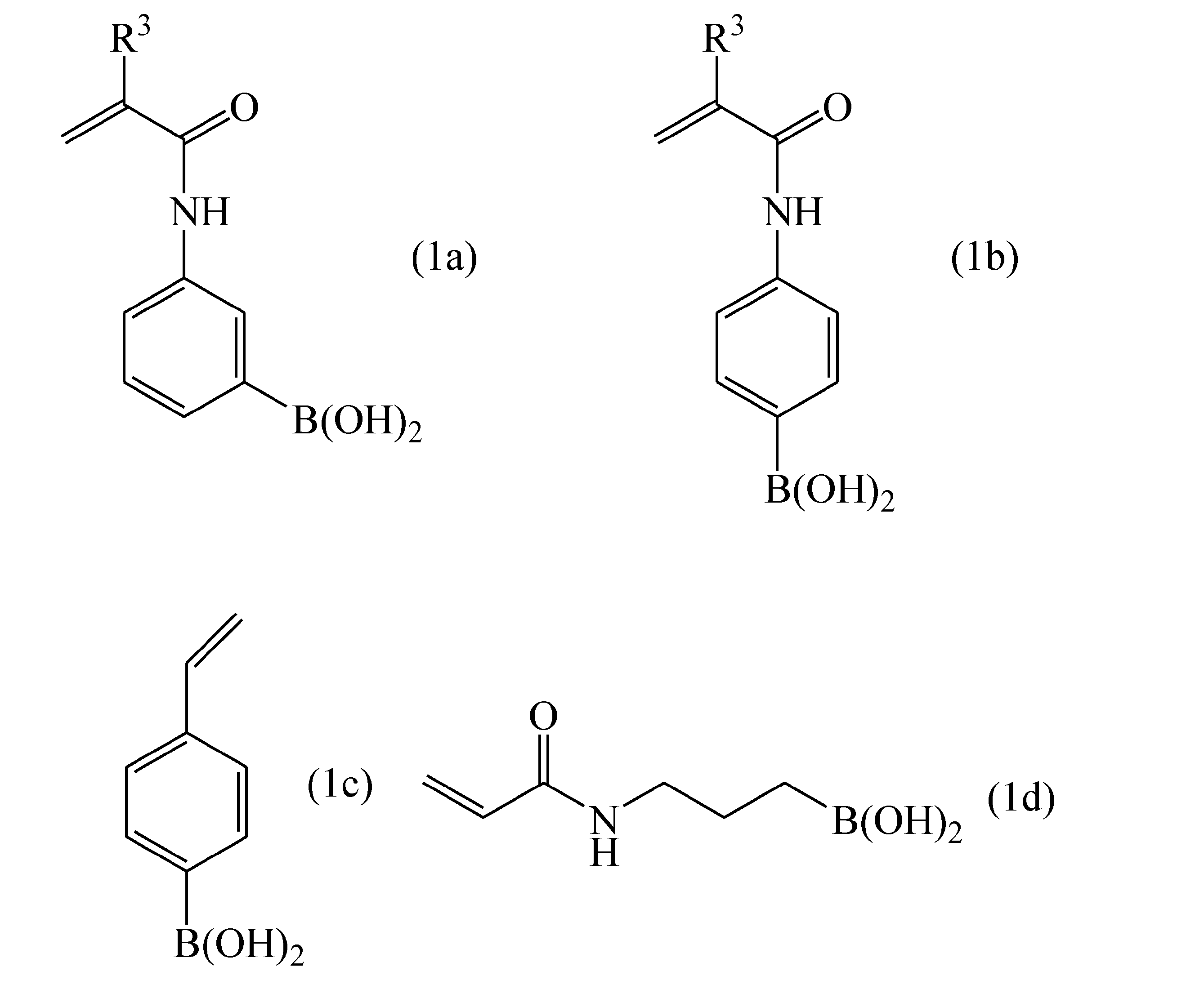
- Preferred specific examples of the compound represented by formula (1) include the following compounds (1a) to (1d), in which R3 in formulas (1a) and (1b) is a hydrogen atom or a methyl group.
- esters of (meth)acrylates and boric acid such as esters of hydroxyethylacrylamide and boric acid, esters of methylol acrylamide and boric acid, esters of hydroxyethyl acrylate and boric acid, and esters of hydroxybutyl acrylate and boric acid.
- the amount of the compound represented by general formula (1) in the easy-adhesion composition is preferably 0.5 to 15 mass %, and more preferably 1 to 10 mass %.
- the easy-adhesion composition used in the present invention contains water in addition to the compound represented by general formula (1).
- the water in the easy-adhesion composition is hardly removed.
- the content of water in the easy-adhesion composition is preferably 40 mass % or less, and more preferably 30 mass % or less.
- the easy-adhesion composition may contain a solvent other than water.
- the solvent that may be contained in the easy-adhesion composition is preferably one that can stabilize and dissolve or disperse the compound represented by general formula (1).
- a solvent is selected from, for example, esters such as ethyl acetate, butyl acetate, and 2-hydroxyethyl acetate; ketones such as methyl ethyl ketone, acetone, cyclohexanone, methyl isobutyl ketone, diethyl ketone, methyl-n-propyl ketone, and acetylacetone; cyclic ethers such as tetrahydrofuran (THF) and dioxane; aliphatic or alicyclic hydrocarbons such as n-hexane and cyclohexane; aromatic hydrocarbons such as toluene and xylene; aliphatic or alicyclic alcohols such as m
- additives such as tackifiers, UV absorbers, antioxidants, and stabilizers such as heat stabilizers, may be blended into the easy-adhesion composition.
- a curable component may be blended into the easy-adhesion composition, and preferably, a compound represented by general formula (2), which is preferably blended into adhesive compositions, may be blended as the curable component.
- the compound represented by general formula (2) will be described later.
- the blending amount is preferably 20 to 80 mass %, and more preferably 40 to 70 mass %.
- a polymerization initiator it is preferable not to mix a polymerization initiator into the easy-adhesion composition used in the first coating step in the present invention, and even if it is mixed, it is preferable that the amount is 3 mass % or less, more preferably 1 mass % or less, and it is particularly preferable that no polymerization initiator is mixed.
- the adhesive composition contains at least a curable component and a polymerization initiator.
- the adhesive composition used in the present invention is preferably an active energy ray-curable adhesive composition.
- Active energy ray-curable adhesive compositions can be divided into radical polymerization curable adhesive compositions and cationic polymerization curable adhesive compositions.
- active energy rays in the wavelength range of 10 nm to less than 380 nm are referred to as ultraviolet rays
- active energy rays in the wavelength range of 380 nm to 800 nm are referred to as visible light.
- the curable component to be incorporated in the radical polymerization curable adhesive composition may be, for example, a compound represented by the following general formula (2): (wherein R4 is a hydrogen atom or a methyl group, R5 and R6 are each independently a hydrogen atom, an alkyl group, a hydroxyalkyl group, an alkoxyalkyl group, or a cyclic ether group, and R5 and R6 may form a cyclic heterocycle).
- the number of carbon atoms in the alkyl moiety of the alkyl group, hydroxyalkyl group, and/or alkoxyalkyl group is not particularly limited, and examples thereof include those having 1 to 4 carbon atoms.
- an example of the cyclic heterocycle which may be formed by R5 and R6 is N-acryloylmorpholine.
- compounds represented by general formula (2) include N-alkyl group-containing (meth)acrylamide derivatives such as N-methyl(meth)acrylamide, N,N-dimethyl(meth)acrylamide, N,N-diethyl(meth)acrylamide, N-isopropyl(meth)acrylamide, N-butyl(meth)acrylamide, and N-hexyl(meth)acrylamide; N-hydroxyalkyl group-containing (meth)acrylamide derivatives such as N-methylol(meth)acrylamide, N-hydroxyethyl(meth)acrylamide, and N-methylol-N-propane(meth)acrylamide; and N-alkoxy group-containing (meth)acrylamide derivatives such as N-methoxymethylacrylamide and N-ethoxymethylacrylamide.
- N-alkyl group-containing (meth)acrylamide derivatives such as N-methyl(meth)acrylamide, N,N-dimethyl(meth)acrylamide, N,N-die
- Examples of (meth)acrylamide derivatives containing a cyclic ether group include heterocyclic (meth)acrylamide derivatives in which the nitrogen atom of the (meth)acrylamide group forms a heterocyclic ring, such as N-acryloylmorpholine, N-acryloylpiperidine, N-methacryloylpiperidine, and N-acryloylpyrrolidine.
- N-hydroxyethylacrylamide and N-acryloylmorpholine are preferred because of their excellent reactivity, ability to produce a cured product with a high modulus of elasticity, and excellent adhesion to polarizers.
- the content of the compound described in general formula (2) in the curable adhesive composition is preferably 20 to 80 mass %, and more preferably 30 to 60 mass %.
- the curable adhesive composition used in the present invention may contain, in addition to the compound represented by general formula (2), other monofunctional radical polymerizable compounds as curable components.
- monofunctional radical polymerizable compounds include various (meth)acrylic acid derivatives having a (meth)acryloyloxy group.
- (meth)acrylic acid (C1-20) alkyl esters such as methyl (meth)acrylate, ethyl (meth)acrylate, n-propyl (meth)acrylate, isopropyl (meth)acrylate, 2-methyl-2-nitropropyl (meth)acrylate, n-butyl (meth)acrylate, isobutyl (meth)acrylate, s-butyl (meth)acrylate, t-butyl (meth)acrylate, n-pentyl (meth)acrylate, t-pentyl (meth)acrylate, 3-pentyl (meth)acrylate, 2,2-dimethylbutyl (meth)acrylate, n-hexyl (meth)acrylate, cetyl (meth)acrylate, n-octyl (meth)acrylate, 2-ethylhexyl (meth)acrylate, 4-methyl-2-propylpentyl
- the (meth)acrylic acid derivatives include, for example, cycloalkyl (meth)acrylates such as cyclohexyl (meth)acrylate and cyclopentyl (meth)acrylate; aralkyl (meth)acrylates such as benzyl (meth)acrylate; 2-isobornyl (meth)acrylate, 2-norbornylmethyl (meth)acrylate, 5-norbornen-2-yl-methyl (meth)acrylate, 3-methyl-2-norbornylmethyl (meth)acrylate, dicyclopentenyl (meth)acrylate, dicyclopentenyloxy (meth)acrylate, and the like.
- cycloalkyl (meth)acrylates such as cyclohexyl (meth)acrylate and cyclopentyl (meth)acrylate
- aralkyl (meth)acrylates such as benzyl (meth)acrylate
- suitable methacrylates include polycyclic (meth)acrylates such as diethyl (meth)acrylate and dicyclopentanyl (meth)acrylate; alkoxy or phenoxy group-containing (meth)acrylates such as 2-methoxyethyl (meth)acrylate, 2-ethoxyethyl (meth)acrylate, 2-methoxymethoxyethyl (meth)acrylate, 3-methoxybutyl (meth)acrylate, ethyl carbitol (meth)acrylate, phenoxyethyl (meth)acrylate, and alkylphenoxy polyethylene glycol (meth)acrylate; and the like.
- dicyclopentenyloxyethyl acrylate and phenoxyethyl acrylate are preferred because of their excellent adhesion to various protective films.
- the (meth)acrylic acid derivatives include hydroxyalkyl (meth)acrylates such as 2-hydroxyethyl (meth)acrylate, 2-hydroxypropyl (meth)acrylate, 3-hydroxypropyl (meth)acrylate, 2-hydroxybutyl (meth)acrylate, 4-hydroxybutyl (meth)acrylate, 6-hydroxyhexyl (meth)acrylate, 8-hydroxyoctyl (meth)acrylate, 10-hydroxydecyl (meth)acrylate, and 12-hydroxylauryl (meth)acrylate.
- hydroxyalkyl (meth)acrylates such as 2-hydroxyethyl (meth)acrylate, 2-hydroxypropyl (meth)acrylate, 3-hydroxypropyl (meth)acrylate, 2-hydroxybutyl (meth)acrylate, 4-hydroxybutyl (meth)acrylate, 6-hydroxyhexyl (meth)acrylate, 8-hydroxyoctyl (meth)acrylate, 10-hydroxydecyl (meth)acryl
- (meth)acrylate hydroxyl group-containing (meth)acrylates such as [4-(hydroxymethyl)cyclohexyl]methyl acrylate, cyclohexanedimethanol mono(meth)acrylate, and 2-hydroxy-3-phenoxypropyl (meth)acrylate; epoxy group-containing (meth)acrylates such as glycidyl (meth)acrylate and 4-hydroxybutyl (meth)acrylate glycidyl ether; 2,2,2-trifluoroethyl (meth)acrylate, 2,2,2-trifluoroethylethyl (meth)acrylate, and 2,2,2-trifluoroethylethyl (meth)acrylate; Halogen-containing (meth)acrylates such as acrylates, tetrafluoropropyl (meth)acrylate, hexafluoropropyl (meth)acrylate, octafluoropentyl (meth)acrylate, heptadeca
- examples of monofunctional radically polymerizable compounds include carboxyl group-containing monomers such as (meth)acrylic acid, carboxyethyl acrylate, carboxypentyl acrylate, itaconic acid, maleic acid, fumaric acid, crotonic acid, and isocrotonic acid.
- Examples of monofunctional radically polymerizable compounds include lactam-based vinyl monomers such as N-vinylpyrrolidone, N-vinyl- ⁇ -caprolactam, and methylvinylpyrrolidone; and vinyl monomers having nitrogen-containing heterocycles such as vinylpyridine, vinylpiperidone, vinylpyrimidine, vinylpiperazine, vinylpyrazine, vinylpyrrole, vinylimidazole, vinyloxazole, and vinylmorpholine.
- lactam-based vinyl monomers such as N-vinylpyrrolidone, N-vinyl- ⁇ -caprolactam, and methylvinylpyrrolidone
- vinyl monomers having nitrogen-containing heterocycles such as vinylpyridine, vinylpiperidone, vinylpyrimidine, vinylpiperazine, vinylpyrazine, vinylpyrrole, vinylimidazole, vinyloxazole, and vinylmorpholine.
- a radical polymerizable compound having an active methylene group can be used as the monofunctional radical polymerizable compound.
- the radical polymerizable compound having an active methylene group is a compound having an active double bond group such as a (meth)acrylic group at the end or in the molecule, and also having an active methylene group.
- the active methylene group include an acetoacetyl group, an alkoxymalonyl group, and a cyanoacetyl group. It is preferable that the active methylene group is an acetoacetyl group.
- radical polymerizable compounds having an active methylene group include acetoacetoxyalkyl (meth)acrylates such as 2-acetoacetoxyethyl (meth)acrylate, 2-acetoacetoxypropyl (meth)acrylate, and 2-acetoacetoxy-1-methylethyl (meth)acrylate; 2-ethoxymalonyloxyethyl (meth)acrylate, 2-cyanoacetoxyethyl (meth)acrylate, N-(2-cyanoacetoxyethyl)acrylamide, N-(2-propionylacetoxybutyl)acrylamide, N-(4-acetoacetoxymethylbenzyl)acrylamide, and N-(2-acetoacetylaminoethyl)acrylamide.
- the radical polymerizable compound having an active methylene group is preferably an acetoacetoxyalkyl (meth)acrylate.
- a polyfunctional radically polymerizable compound having two or more functionalities can be blended as a curable component constituting the radical polymerization curable adhesive composition.
- polyfunctional radically polymerizable compounds include polyfunctional (meth)acrylamide derivatives such as N,N'-methylenebis(meth)acrylamide, tripropylene glycol di(meth)acrylate, tetraethylene glycol di(meth)acrylate, 1,6-hexanediol di(meth)acrylate, 1,9-nonanediol di(meth)acrylate, 1,10-decanediol diacrylate, 2-ethyl-2-butylpropanediol di(meth)acrylate, bisphenol A di(meth)acrylate, bisphenol A ethylene oxide adduct di(meth)acrylate, bisphenol A propylene oxide adduct di(meth)acrylate, bisphenol A diglycidyl ether di(meth)acrylate, and bisphenol A digly
- esters of (meth)acrylic acid and polyhydric alcohols such as ethyl acrylate, neopentyl glycol di(meth)acrylate, tricyclodecane dimethanol di(meth)acrylate, cyclic trimethylolpropane formal (meth)acrylate, dioxane glycol di(meth)acrylate, trimethylolpropane tri(meth)acrylate, pentaerythritol tri(meth)acrylate, pentaerythritol tetra(meth)acrylate, dipentaerythritol penta(meth)acrylate, dipentaerythritol hexa(meth)acrylate, and EO-modified diglycerin tetra(meth)acrylate; and 9,9-bis[4-(2-(meth)acryloyloxyethoxy)phenyl]fluorene.
- Specific examples include Aronix M-220 (manufactured by Toagosei Co., Ltd.), Light Acrylate 1,9ND-A (manufactured by Kyoeisha Chemical Co., Ltd.), Light Acrylate DGE-4A (manufactured by Kyoeisha Chemical Co., Ltd.), Light Acrylate DCP-A (manufactured by Kyoeisha Chemical Co., Ltd.), SR-531 (manufactured by Sartomer Co., Ltd.), and CD-536 (manufactured by Sartomer Co., Ltd.).
- epoxy (meth)acrylates various epoxy (meth)acrylates, urethane (meth)acrylates, polyester (meth)acrylates, and various (meth)acrylate monomers may be used as needed.
- polyfunctional (meth)acrylamide derivatives have a high polymerization rate and excellent productivity, and also have excellent crosslinking properties when the adhesive composition is cured, so they are preferably contained in the adhesive composition.
- the amount of the monofunctional radically polymerizable compound in the adhesive composition is preferably 30 to 90 mass%, and more preferably 50 to 80 mass%.
- the amount of the polyfunctional radically polymerizable compound in the adhesive composition is preferably 10 to 70 mass%, and more preferably 20 to 50 mass%.
- the adhesive composition used in the present invention may contain a compound represented by the general formula (1) as a curable component.
- the content of the compound represented by the general formula (1) in the curable adhesive composition is preferably 0.1 to 7 mass %, and more preferably 1 to 5 mass %.
- the adhesive composition used in the present invention can be used as an active energy ray-curable adhesive composition when the curable component is an active energy ray-curable component.
- ultraviolet light or visible light it is preferable to contain a photopolymerization initiator as the polymerization initiator.
- the photopolymerization initiator is appropriately selected depending on the active energy ray.
- a photopolymerization initiator that is cleaved by ultraviolet or visible light is used.
- the photopolymerization initiator include benzophenone-based compounds such as benzil, benzophenone, benzoylbenzoic acid, and 3,3'-dimethyl-4-methoxybenzophenone; aromatic ketone compounds such as 4-(2-hydroxyethoxy)phenyl(2-hydroxy-2-propyl)ketone, ⁇ -hydroxy- ⁇ , ⁇ '-dimethylacetophenone, 2-methyl-2-hydroxypropiophenone, and ⁇ -hydroxycyclohexylphenylketone; acetophenone-based compounds such as methoxyacetophenone, 2,2-dimethoxy-2-phenylacetophenone, 2,2-diethoxyacetophenone, and 2-methyl-1-[4-(methylthio)-phenyl]-2-morpholinopropane
- benzoin ether compounds such as benzoin butyl ether and anisoin methyl ether
- aromatic ketal compounds such as benzyl dimethyl ketal
- aromatic sulfonyl chloride compounds such as 2-naphthalenesulfonyl chloride
- photoactive oxime compounds such as 1-phenone-1,1-propanedione-2-(o-ethoxycarbonyl)oxime
- thioxanthone compounds such as thioxanthone, 2-chlorothioxanthone, 2-methylthioxanthone, 2,4-dimethylthioxanthone, isopropylthioxanthone, 2,4-dichlorothioxanthone, 2,4-diethylthioxanthone, 2,4-diisopropylthioxanthone, and dodecylthioxanthone
- camphorquinone such as benzoin butyl ether and anisoin
- the amount is preferably 0.5 to 10 mass %, and more preferably 1 to 5 mass %.
- an active energy ray-curable adhesive composition As a visible light-curable type, it is preferable to use a photopolymerization initiator that is highly sensitive to light of 380 nm or more. Photopolymerization initiators that are highly sensitive to light of 380 nm or more will be described later.
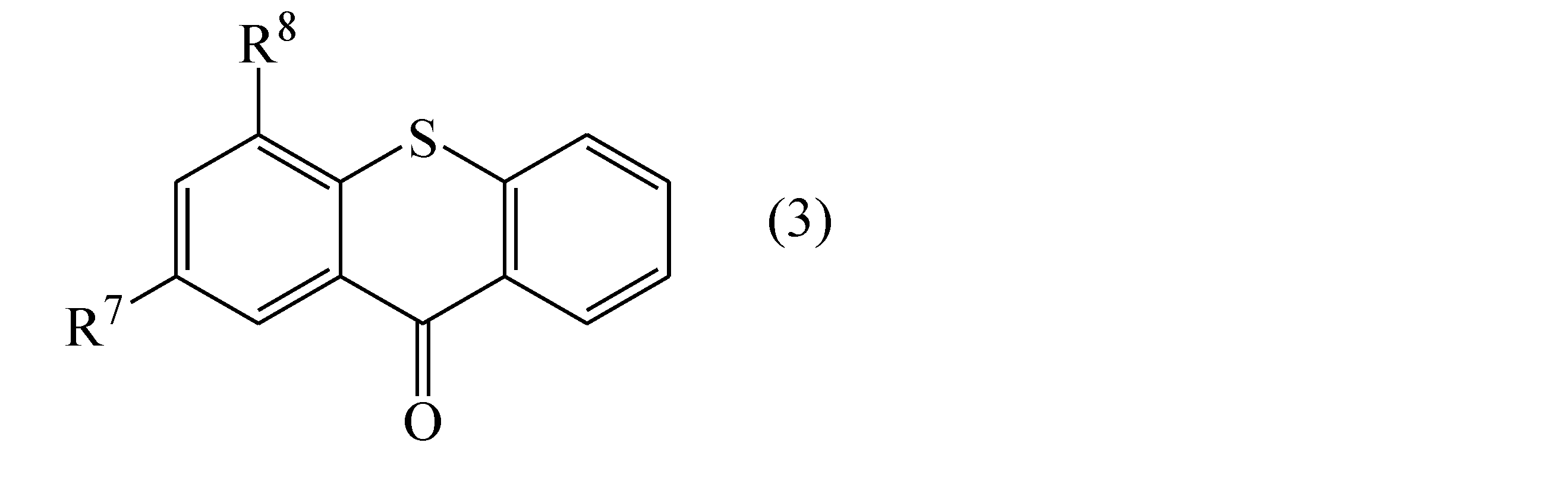
- the photopolymerization initiator may be a compound represented by the following general formula (3): (wherein R 7 and R 8 are -H, -CH 2 CH 3 , -iPr or Cl, and R 7 and R 8 may be the same or different) is used alone, or it is preferable to use a compound represented by general formula (3) in combination with a photopolymerization initiator highly sensitive to light of 380 nm or more, which will be described later. When a compound represented by general formula (3) is used, the adhesiveness is superior to that when a photopolymerization initiator highly sensitive to light of 380 nm or more is used alone.
- diethylthioxanthone in which R 7 and R 8 are -CH 2 CH 3, is particularly preferable.
- the amount of the compound represented by general formula (3) in the active energy ray-curable adhesive composition is preferably 0.1 to 10 mass%, more preferably 1 to 5 mass%.
- polymerization initiator aid examples include triethylamine, diethylamine, N-methyldiethanolamine, ethanolamine, 4-dimethylaminobenzoic acid, methyl 4-dimethylaminobenzoate, ethyl 4-dimethylaminobenzoate, and isoamyl 4-dimethylaminobenzoate, with ethyl 4-dimethylaminobenzoate being particularly preferable.
- the amount added is preferably 0.1 to 10% by mass, and more preferably 1 to 5% by mass.
- a known photopolymerization initiator can be used in combination. Since the optical functional layer and the base film having UV absorbing ability do not transmit light of 380 nm or less, it is preferable to use a photopolymerization initiator that is highly sensitive to light of 380 nm or more.
- examples include 2-methyl-1-(4-methylthiophenyl)-2-morpholinopropan-1-one, 2-benzyl-2-dimethylamino-1-(4-morpholinophenyl)-butanone-1, 2-(dimethylamino)-2-[(4-methylphenyl)methyl]-1-[4-(4-morpholinyl)phenyl]-1-butanone, 2,4,6-trimethylbenzoyl-diphenyl-phosphine oxide, bis(2,4,6-trimethylbenzoyl)-phenylphosphine oxide, bis( ⁇ 5-2,4-cyclopentadiene-1-yl)-bis(2,6-difluoro-3-(1H-pyrrol-1-yl)-phenyl)titanium, and the like.
- the adhesive composition used in the present invention may contain an acrylic oligomer obtained by polymerizing a (meth)acrylic monomer.
- an acrylic oligomer obtained by polymerizing a (meth)acrylic monomer.
- the active energy ray-curable adhesive composition has a low viscosity, and therefore it is preferable that the acrylic oligomer obtained by polymerizing a (meth)acrylic monomer also has a low viscosity.
- the acrylic oligomer that has a low viscosity and can prevent the curing shrinkage of the adhesive layer one having a weight average molecular weight (Mw) of preferably 15,000 or less, more preferably 10,000 or less, and particularly preferably 5,000 or less is preferred.
- the weight average molecular weight (Mw) of the acrylic oligomer is preferably 500 or more, more preferably 1,000 or more, and particularly preferably 1,500 or more.
- (meth)acrylic monomers constituting acrylic oligomers include methyl (meth)acrylate, ethyl (meth)acrylate, n-propyl (meth)acrylate, isopropyl (meth)acrylate, 2-methyl-2-nitropropyl (meth)acrylate, n-butyl (meth)acrylate, isobutyl (meth)acrylate, S-butyl (meth)acrylate, t-butyl (meth)acrylate, n-pentyl (meth)acrylate, t-pentyl (meth)acrylate, 3-pentyl (meth)acrylate, 2,2-dimethylbutyl (meth)acrylate, n-hexyl (meth)acrylate, cetyl (meth)acrylate, (meth)acrylic acid (C1-20) alkyl esters such as (meth)acrylic acid (C1-20) alkyl esters, such as n-octyl (
- acrylic oligomer (E) examples include “ARUFON” manufactured by Toagosei Co., Ltd., “Actflow” manufactured by Soken Chemical & Engineering Co., Ltd., and "JONCRYL” manufactured by BASF Japan Ltd.
- the amount of acrylic oligomer in the adhesive composition is preferably 3 to 40% by mass, and more preferably 5 to 20% by mass.
- the adhesive composition used in the present invention may contain a silane coupling agent.
- silane coupling agents include active energy ray-curable compounds such as vinyltrichlorosilane, vinyltrimethoxysilane, vinyltriethoxysilane, 2-(3,4-epoxycyclohexyl)ethyltrimethoxysilane, 3-glycidoxypropyltrimethoxysilane, 3-glycidoxypropylmethyldiethoxysilane, 3-glycidoxypropyltriethoxysilane, p-styryltrimethoxysilane, 3-methacryloxypropylmethyldimethoxysilane, 3-methacryloxypropyltrimethoxysilane, 3-methacryloxypropylmethyldiethoxysilane, 3-methacryloxypropyltriethoxysilane, and 3-acryloxypropyltrimethoxysilane.
- silane coupling agents other than those mentioned above that are not curable by active energy rays include 3-ureidopropyltriethoxysilane, 3-chloropropyltrimethoxysilane, 3-mercaptopropylmethyldimethoxysilane, 3-mercaptopropyltrimethoxysilane, bis(triethoxysilylpropyl)tetrasulfide, 3-isocyanatopropyltriethoxysilane, and imidazole silane.
- the adhesive composition used in the present invention may be a cationic polymerization curable adhesive composition.
- the cationic polymerizable compounds used in the cationic polymerization curable adhesive composition are classified into monofunctional cationic polymerizable compounds having one cationic polymerizable functional group in the molecule and polyfunctional cationic polymerizable compounds having two or more cationic polymerizable functional groups in the molecule. Since the liquid viscosity of the monofunctional cationic polymerizable compound is relatively low, the liquid viscosity can be reduced by including it in the cationic polymerization curable adhesive composition.
- the monofunctional cationic polymerizable compound often has a functional group that exhibits various functions, and by including it in the cationic polymerization curable adhesive composition, various functions can be exhibited in the cationic polymerization curable adhesive composition and/or the cured product of the cationic polymerization curable adhesive composition.
- the polyfunctional cationic polymerizable compound can three-dimensionally crosslink the cured product of the cationic polymerization curable adhesive composition, so it is preferable to include it in the cationic polymerization curable adhesive composition.
- the ratio of the monofunctional cationic polymerizable compound to the polyfunctional cationic polymerizable compound is preferably in the range of 10 to 1000 parts by mass of the polyfunctional cationic polymerizable compound per 100 parts by mass of the monofunctional cationic polymerizable compound.
- the cationic polymerizable functional group include an epoxy group, an oxetanyl group, and a vinyl ether group.
- compounds having an epoxy group include an aliphatic epoxy compound, an alicyclic epoxy compound, and an aromatic epoxy compound.
- the cationic polymerizable adhesive composition of the present invention is particularly preferably one that contains an alicyclic epoxy compound because of its excellent curability and adhesiveness.
- Examples of the alicyclic epoxy compound include 3,4-epoxycyclohexylmethyl-3,4-epoxycyclohexanecarboxylate, caprolactone-modified products, trimethylcaprolactone-modified products, and valerolactone-modified products of 3,4-epoxycyclohexylmethyl-3,4-epoxycyclohexanecarboxylate, and specifically, CELLOXIDE 2021, CELLOXIDE 2021A, CELLOXIDE 2021P, CELLOXIDE 2081, CELLOXIDE 2083, CELLOXIDE 2085 (all manufactured by Daicel Chemical Industries, Ltd.), Cyracure UVR-61 No.
- Examples of compounds having an oxetanyl group include 3-ethyl-3-hydroxymethyloxetane, 1,4-bis[(3-ethyl-3-oxetanyl)methoxymethyl]benzene, 3-ethyl-3-(phenoxymethyl)oxetane, di[(3-ethyl-3-ox Examples of such compounds include 3-ethyl-3-(2-ethylhexyloxymethyl)oxetane, phenol novolak oxetane, and the like.
- ARON OXETANE OXT-101, ARON OXETANE OXT-121, ARON OXETANE OXT-211, ARON OXETANE OXT-221, ARON OXETANE OXT-212 (all manufactured by Toagosei Co., Ltd.) and the like are commercially available.
- Compounds having a vinyl ether group are preferably contained since they have the effect of improving the curing properties of the cationically polymerizable adhesive composition and reducing the liquid viscosity of the composition.
- Examples of compounds having an ether group include 2-hydroxyethyl vinyl ether, diethylene glycol monovinyl ether, 4-hydroxybutyl vinyl ether, diethylene glycol monovinyl ether, triethylene glycol divinyl ether, cyclohexane dimethanol divinyl ether, cyclohexane dimethanol monovinyl ether, tricyclodecane vinyl ether, cyclohexyl vinyl ether, methoxyethyl vinyl ether, ethoxyethyl vinyl ether, and pentaerythritol tetravinyl ether.
- the cationic polymerization curable adhesive composition contains at least one compound selected from the compounds having an epoxy group, the compounds having an oxetanyl group, and the compounds having a vinyl ether group described above as a curable component, and since all of these cure by cationic polymerization, a photocationic polymerization initiator is blended.
- This photocationic polymerization initiator generates cationic species or Lewis acids when exposed to active energy rays such as visible light, ultraviolet light, X-rays, and electron beams, and starts the polymerization reaction of the epoxy group or oxetanyl group.
- a photoacid generator described below is preferably used as the photocationic polymerization initiator.
- the cationic polymerizable adhesive composition when used as a visible light curable composition, it is preferable to use a photocationic polymerization initiator that is particularly sensitive to light of 380 nm or more.
- photocationic polymerization initiators are generally compounds that exhibit maximum absorption in the vicinity of 300 nm or shorter wavelength range, by blending a photosensitizer that exhibits maximum absorption in a longer wavelength range, specifically light of wavelengths longer than 380 nm, it is possible to promote the generation of cationic species or acid from the photocationic polymerization initiator by reacting to light of wavelengths in this vicinity.
- photosensitizers include anthracene compounds, pyrene compounds, carbonyl compounds, organic sulfur compounds, persulfides, redox compounds, azo and diazo compounds, halogen compounds, photoreducible dyes, etc., and these may be used in combination of two or more types.
- anthracene compounds are preferable because they have excellent photosensitizing effects, and specific examples include Anthracure UVS-1331 and Anthracure UVS-1221 (manufactured by Kawasaki Chemical Industries, Ltd.).
- the content of the photosensitizer is preferably 0.1% to 5% by mass, and more preferably 0.5% to 3% by mass.
- the active energy ray curable adhesive composition may contain a photoacid generator.
- the active energy ray curable adhesive composition contains a photoacid generator, the water resistance and durability of the adhesive layer can be dramatically improved compared to when the adhesive composition does not contain a photoacid generator.
- the photoacid generator can be represented by the following general formula (3).
- the counter anion X ⁇ in the general formula (4) is not particularly limited in principle, but is preferably a non-nucleophilic anion.
- the counter anion X ⁇ is a non-nucleophilic anion, nucleophilic reactions are unlikely to occur in the cations coexisting in the molecule or in various materials used in combination, and as a result, it is possible to improve the stability over time of the photoacid generator represented by the general formula (4) itself and the composition using it.
- the non-nucleophilic anion here refers to an anion that has a low ability to cause a nucleophilic reaction.
- Examples of such anions include PF 6 ⁇ , SbF 6 ⁇ , AsF 6 ⁇ , SbCl 6 ⁇ , BiCl 5 ⁇ , SnCl 6 ⁇ , ClO 4 ⁇ , B(C 6 H 5 ) 4 ⁇ , dithiocarbamate anion, SCN ⁇ and the like.
- the first optical film used in the present invention may be a polarizer, a transparent protective film, a retardation film, or the like.
- a polarizer when used as the first optical film, it is preferred because of excellent adhesion between the polarizer and the adhesive layer.
- the polarizer is not particularly limited, and various polarizers can be used.
- polarizers include hydrophilic polymer films such as polyvinyl alcohol films, partially formalized polyvinyl alcohol films, and partially saponified ethylene-vinyl acetate copolymer films, which have been subjected to uniaxial stretching after iodine has been adsorbed thereon.
- the thickness of the polarizer can be, for example, 3 to 20 ⁇ m.
- a thin polarizer having a thickness of 3 ⁇ m or more and 15 ⁇ m or less as the polarizer.
- the thickness is 12 ⁇ m or less, and even more preferable that the thickness is 10 ⁇ m or less, and especially preferable that the thickness is 8 ⁇ m or less.
- Such a thin polarizer has little thickness unevenness, excellent visibility, and also has excellent durability against thermal shock due to little dimensional change.
- a polarizer obtained by dyeing a polyvinyl alcohol-based film with iodine and stretching it uniaxially can be produced, for example, by dyeing the polyvinyl alcohol by immersing it in an aqueous solution of iodine and stretching it to 3 to 7 times its original length.
- the solution may contain boric acid, zinc sulfate, zinc chloride, etc., or it may be immersed in an aqueous solution of potassium iodide, etc.
- the polyvinyl alcohol-based film may be immersed in water and washed before dyeing.
- Stretching may be performed after dyeing with iodine, or it may be stretched while dyeing, or it may be dyed with iodine after stretching. Stretching may be performed in an aqueous solution of boric acid, potassium iodide, etc., or in a water bath.
- the polarizer preferably contains boric acid from the viewpoints of stretching stability and humidification reliability. Furthermore, the boric acid content in the polarizer is preferably 22% by mass or less, and more preferably 20% by mass or less, based on the total amount of the polarizer, from the viewpoints of suppressing the occurrence of through cracks. From the viewpoints of stretching stability and humidification reliability, the boric acid content in the polarizer is preferably 10% by mass or more, and more preferably 12% by mass or more, based on the total amount of the polarizer.
- thin polarizers include: Patent No. 4751486 specification, Patent No. 4751481 specification, Patent No. 4815544 specification, Patent No. 5048120 specification, International Publication No. WO 2014/077599, International Publication No. WO 2014/077636, or thin polarizers obtained by the manufacturing methods described therein.
- the thin polarizer is preferably obtained by a manufacturing method including a step of stretching in a boric acid aqueous solution as described in Patent Nos. 4751486, 4751481, and 4815544, among which a step of stretching in a laminate and a step of dyeing, because it can be stretched at a high magnification and the polarization performance can be improved.
- a manufacturing method including a step of supplementary air stretching before stretching in a boric acid aqueous solution as described in Patent Nos. 4751481 and 4815544.
- These thin polarizers can be obtained by a manufacturing method including a step of stretching a polyvinyl alcohol resin (hereinafter also referred to as PVA-based resin) layer and a resin substrate for stretching in a laminate and a step of dyeing.
- PVA-based resin polyvinyl alcohol resin
- the second optical film used in the present invention may be a polarizer, a transparent protective film, a retardation film, or the like.
- a polarizer when used as the first optical film, it is preferable to use a transparent protective film as the second optical film.
- thermoplastic resin excellent in transparency, mechanical strength, thermal stability, moisture blocking property, isotropy, etc.
- thermoplastic resins include cellulose resins such as triacetyl cellulose-based resin films, polyester resins, polyethersulfone resins, polysulfone resins, polycarbonate resins, polyamide resins, polyimide resins, polyolefin resins, (meth)acrylic resins, cyclic polyolefin resins (norbornene-based resins), polyarylate resins, polystyrene resins, polyvinyl alcohol resins, and mixtures thereof.
- the transparent protective film may contain one or more suitable additives.
- additives include ultraviolet absorbers, antioxidants, lubricants, plasticizers, release agents, coloring inhibitors, flame retardants, nucleating agents, antistatic agents, pigments, colorants, etc.
- the content of the above thermoplastic resin in the transparent protective film is preferably 50 to 100% by weight, more preferably 50 to 99% by weight, even more preferably 60 to 98% by weight, and particularly preferably 70 to 97% by weight. If the content of the thermoplastic resin in the transparent protective film is 50% by weight or less, the inherent high transparency of the thermoplastic resin may not be fully exhibited.
- the transparent protective film one having excellent transparency, mechanical strength, thermal stability, moisture blocking properties, isotropy, etc. is preferred, and one having a moisture permeability of 150 g/ m2 /24 h or less is more preferred, one having a moisture permeability of 140 g/ m2 /24 h or less is particularly preferred, and one having a moisture permeability of 120 g/ m2 /24 h or less is even more preferred.
- Functional layers such as a hard coat layer, an anti-reflection layer, an anti-sticking layer, a diffusion layer, or an anti-glare layer can be provided on the surface of the transparent protective film to which the polarizer is not attached.
- the above-mentioned functional layers such as the hard coat layer, the anti-reflection layer, the anti-sticking layer, the diffusion layer, and the anti-glare layer can be provided on the transparent protective film itself, or can be provided separately from the transparent protective film.
- the thickness of the transparent protective film can be determined as appropriate, but is generally about 1 to 500 ⁇ m in terms of strength, ease of handling, thinness, etc., with 1 to 300 ⁇ m being preferred, and 5 to 200 ⁇ m being more preferred. Furthermore, 10 to 200 ⁇ m is more preferred, and 20 to 80 ⁇ m is more preferred.
- a retardation film having a front retardation of 40 nm or more and/or a thickness retardation of 80 nm or more can be used as the transparent protective film.
- the front retardation is usually controlled to be in the range of 40 to 200 nm
- the thickness retardation is usually controlled to be in the range of 80 to 300 nm.
- the retardation film also functions as the transparent protective film, making it possible to achieve a thinner film.
- phase difference films examples include birefringent films made by uniaxially or biaxially stretching polymer materials, oriented films of liquid crystal polymers, and films in which an oriented layer of liquid crystal polymer is supported by a film. There are no particular restrictions on the thickness of the phase difference film, but it is generally around 20 to 150 ⁇ m.
- the retardation film may be any of the following formulas (1) to (3): 0.70 ⁇ Re[450]/Re[550] ⁇ 0.97...(1) 1.5 ⁇ 10 -3 ⁇ n ⁇ 6 ⁇ 10 -3 ...(2) 1.13 ⁇ NZ ⁇ 1.50...(3) (wherein Re[450] and Re[550] are in-plane retardation values of the retardation film measured with light having wavelengths of 450 nm and 550 nm at 23° C., respectively; ⁇ n is in-plane birefringence, which is nx-ny, where nx and ny are the refractive indices in the slow axis direction and fast axis direction of the retardation film, respectively; and NZ is the ratio of nx-nz, which is the thickness direction birefringence, to nx-ny, which is the in-plane birefringence, where nz is the refractive index in the thickness direction of the retardation film.)
- a reverse wavelength dispersion type retardation film that satis
- the method for producing a laminated optical film according to the present invention is a method for producing a laminated optical film in which at least a first optical film and a second optical film are laminated via an adhesive layer, and includes a first coating step of coating an easy-adhesion composition containing at least a compound represented by general formula (1) and water on the bonding surface of the first optical film while transporting the first optical film, a second coating step of coating an adhesive composition containing at least a curable component and a polymerization initiator on the bonding surface of the second optical film while transporting the second optical film, a bonding step of bonding the first optical film and the second optical film, and a bonding step of bonding the first optical film and the second optical film via an adhesive layer formed by irradiating the first optical film side or the second optical film side with active energy rays to cure at least the adhesive composition.
- a first coating step of coating an easy-adhesion composition containing at least a compound represented by general formula (1) and water on the bonding surface of the
- the method for producing a laminated optical film according to the present invention includes a first coating step of coating an easy-adhesion composition containing at least a compound represented by general formula (1) and water on the lamination surface of the first optical film while transporting the first optical film, and a second coating step of coating an adhesive composition containing at least a curable component and a polymerization initiator on the lamination surface of the second optical film while transporting the second optical film.
- ⁇ when the film thickness of the easy-adhesion composition after the first coating step is ⁇ and the film thickness of the adhesive composition after the second coating step is ⁇ , ⁇ is designed to be greater than ⁇ .
- ⁇ is preferably greater than 1.0 ⁇ , and more preferably greater than 1.1 ⁇ .
- the film thickness ⁇ of the easy-adhesion composition after the first coating step is preferably 200 to 2000 nm, and more preferably 300 to 1500 nm.
- the film thickness ⁇ of the adhesive composition after the second coating step is preferably 200 to 2000 nm, and more preferably 300 to 1500 nm.
- the method for applying the easy-adhesion composition and adhesive composition is appropriately selected depending on the viscosity of the composition and the desired thickness, and examples include a reverse coater, gravure coater (direct, reverse or offset), bar reverse coater, roll coater, die coater, bar coater, and rod coater.
- the viscosity of the easy-adhesion composition and adhesive composition is preferably 0.1 to 200 mPa ⁇ s, more preferably 1 to 100 mPa ⁇ s, and most preferably 5 to 50 mPa ⁇ s. If the viscosity of the composition is high, it is not preferable because the surface smoothness after application is poor and a poor appearance occurs. For this reason, each composition can be heated or cooled to adjust the viscosity to a preferred range before application.
- the first optical film and/or the second optical film may be subjected to a surface modification treatment before the coating step.
- a surface modification treatment when a polarizer is used as the first optical film, it is preferable to perform the surface modification treatment.
- the surface modification treatment include corona treatment, plasma treatment, and itro treatment, and corona treatment is particularly preferable.
- corona treatment reactive functional groups such as carbonyl groups and amino groups are generated on the polarizer surface, improving adhesion with the adhesive layer.
- the ashing effect removes foreign matter from the surface and reduces surface unevenness, making it possible to produce a laminated optical film with excellent appearance characteristics.
- the first optical film and the second optical film are bonded together using a roll laminator or the like via the adhesive composition and the adhesive composition applied as described above.
- the time required from the end of the first coating step to the start of the lamination step is within 10 seconds, and more preferably within 5 seconds.
- the film thickness ⁇ of the easy-adhesion composition after the first coating step, the film thickness ⁇ ' of the easy-adhesion composition when the first optical film and the second optical film are bonded together, and further the film thickness ⁇ of the adhesive composition after the second coating step can be measured by in-line measurement while the first optical film and the second optical film are being transported.
- the film thickness meter used for in-line measurement it is preferable to use an optical (non-contact) film thickness meter.
- the optical (non-contact) film thickness meter there are no particular limitations on the optical (non-contact) film thickness meter, and examples thereof include a spectral interference film thickness meter, a reflection spectral film thickness meter, and a confocal film thickness meter.
- a spectral interference film thickness meter that can measure the thickness of the coating film over the entire width is preferable.
- the first optical film and the second optical film are bonded to each other via an adhesive layer formed by curing at least the adhesive composition by irradiating the first optical film side or the second optical film side with active energy rays.
- the irradiation direction of the active energy rays can be any appropriate direction.
- any suitable irradiation conditions can be adopted as long as they are conditions that can at least cure the adhesive composition.
- the acceleration voltage of the electron beam irradiation is preferably 5 kV to 300 kV, more preferably 10 kV to 250 kV. If the acceleration voltage is less than 5 kV, the electron beam may not reach the adhesive, resulting in insufficient curing, and if the acceleration voltage exceeds 300 kV, the penetration force through the sample may be too strong, resulting in damage to the first optical film and the second optical film.
- the irradiation dose is 5 to 100 kGy, more preferably 10 to 75 kGy.
- the adhesive may not be cured sufficiently, and if it exceeds 100 kGy, the first optical film and the second optical film may be damaged, resulting in a decrease in mechanical strength and yellowing, and the specified optical characteristics may not be obtained.
- Electron beam irradiation is usually performed in an inert gas, but may be performed in air or with a small amount of oxygen introduced if necessary.
- appropriate oxygen introduction can be used to intentionally cause oxygen inhibition on the first and second optical film surfaces that are first hit by the electron beam, preventing damage to the first and second optical films and allowing the electron beam to be efficiently irradiated only to the adhesive.
- the active energy rays those including visible light in the wavelength range of 380 nm to 450 nm, and in particular active energy rays with the greatest irradiation amount of visible light in the wavelength range of 380 nm to 450 nm.
- a second optical film with ultraviolet absorption ability for example an ultraviolet-opaque transparent protective film, light with a wavelength shorter than approximately 380 nm is absorbed, so that light with a wavelength shorter than 380 nm does not reach the adhesive composition and does not contribute to the polymerization reaction.
- the ratio of the integrated illuminance in the wavelength range of 380 to 440 nm to the integrated illuminance in the wavelength range of 250 to 370 nm is preferably 100:0 to 100:50, more preferably 100:0 to 100:40.
- the active energy ray is preferably a gallium-encapsulated metal halide lamp or an LED light source that emits light in the wavelength range of 380 to 440 nm.
- a light source containing ultraviolet rays and visible light such as a low pressure mercury lamp, a medium pressure mercury lamp, a high pressure mercury lamp, an ultra-high pressure mercury lamp, an incandescent lamp, a xenon lamp, a halogen lamp, a carbon arc lamp, a metal halide lamp, a fluorescent lamp, a tungsten lamp, a gallium lamp, an excimer laser, or sunlight can be used, and a bandpass filter can be used to block ultraviolet rays with a wavelength shorter than 380 nm.
- the line speed depends on the curing time of the adhesive composition, but is preferably 1 to 500 m/min, more preferably 5 to 300 m/min, and even more preferably 10 to 100 m/min. If the line speed is too slow, productivity will be poor, or the damage to the first optical film or the second optical film will be too great, making it impossible to produce a laminated optical film that can withstand durability tests and the like. If the line speed is too high, the adhesive composition will not cure sufficiently, and the desired adhesion may not be obtained.
- the laminated optical film is formed by laminating at least a first optical film and a second optical film via an adhesive layer, but may also have a pressure-sensitive adhesive layer for bonding to other members such as a liquid crystal cell.
- the pressure-sensitive adhesive forming the pressure-sensitive adhesive layer is not particularly limited, and may be appropriately selected and used, for example, from a base polymer such as an acrylic polymer, a silicone polymer, a polyester, a polyurethane, a polyamide, a polyether, a fluorine-based polymer, or a rubber-based polymer.
- a pressure-sensitive adhesive having excellent optical transparency, suitable adhesive properties such as wettability, cohesiveness, and adhesiveness, and excellent weather resistance and heat resistance, such as an acrylic pressure-sensitive adhesive may be preferably used.
- the adhesive layer can be provided on one or both sides of the polarizing film or optical film as a superimposed layer of different compositions or types. When provided on both sides, the adhesive layers on the front and back of the polarizing film or optical film can be of different compositions, types, thicknesses, etc.
- the thickness of the adhesive layer can be appropriately determined depending on the intended use, adhesive strength, etc., and is generally 1 to 500 ⁇ m, preferably 1 to 200 ⁇ m, and particularly preferably 1 to 100 ⁇ m.
- a separator is temporarily attached to cover the exposed surface of the adhesive layer to prevent contamination until it is put into practical use. This prevents contact with the adhesive layer during normal handling.
- any suitable thin material such as plastic film, rubber sheet, paper, cloth, nonwoven fabric, net, foam sheet, metal foil, or laminates thereof, coated as necessary with a suitable release agent such as silicone, long-chain alkyl, fluorine, or molybdenum sulfide, may be used in accordance with conventional methods.
- the laminated optical film can be preferably used to form various devices such as liquid crystal displays.
- the formation of liquid crystal displays can be carried out in a conventional manner. That is, liquid crystal displays are generally formed by appropriately assembling components such as a liquid crystal cell, a polarizing film or an optical film, and, if necessary, a lighting system, and incorporating a driving circuit, but in the present invention, there are no particular limitations other than the use of the polarizing film or optical film according to the present invention, and the method can be carried out in a conventional manner.
- the liquid crystal cell any type can be used, such as TN type, STN type, ⁇ type, etc.
- suitable liquid crystal display devices such as those in which an optical laminate is disposed on one or both sides of a liquid crystal cell, or those in which a backlight or reflector is used in the lighting system.
- the optical laminate according to the present invention can be disposed on one or both sides of a liquid crystal cell.
- optical laminates When optical laminates are disposed on both sides, they may be the same or different.
- suitable components such as a diffuser plate, anti-glare layer, anti-reflection film, protective plate, prism array, lens array sheet, light diffuser plate, backlight, etc. can be disposed in suitable positions in one or more layers.
- a laminate in which a 9 ⁇ m-thick PVA layer was formed on an amorphous PET substrate was subjected to air-assisted stretching at a stretching temperature of 130° C. to produce a stretched laminate, and then the stretched laminate was dyed to produce a colored laminate, and the colored laminate was further stretched in boric acid water at a stretching temperature of 65° C. to produce an optical film laminate including a 5 ⁇ m-thick PVA layer, which was stretched together with the amorphous PET substrate to a total stretch ratio of 5.94 times.
- the PVA molecules of the PVA layer formed on the amorphous PET substrate were highly oriented, and an optical film laminate including a 5.5 ⁇ m-thick PVA layer was obtained, which constitutes a thin polarizer in which iodine adsorbed by dyeing was highly oriented in one direction as a polyiodine ion complex.
- the thin polarizer obtained here was used as the first optical film.
- Transparent protective film Triacetyl cellulose resin film (product name "TJ25", manufactured by Fujifilm Corporation) The above transparent protective film was used as the second optical film.
- Visible light (gallium-filled metal halide lamp) was used as the active energy ray.
- Irradiation device Light HAMMER10 manufactured by Fusion UV Systems, Inc.
- Bulb V bulb Peak illuminance: 1600 mW/cm 2 , cumulative irradiation amount: 1000/mJ/cm 2 (wavelength: 380 to 440 nm).
- the illuminance of visible light was measured using a Sola-Check system manufactured by Solatell.
- Example 1 (Preparation of Easy-Adhesion Composition) An easily adhesive composition was prepared in the following proportions: 65 mass % N-acryloylmorpholine (compound represented by general formula (2) (trade name “ACMO”, manufactured by Kojinsha)), 7 mass % 3-methacrylamidephenylboronic acid (compound represented by general formula (1) (trade name "MAPBA”, manufactured by Junsei Chemical Industry Co., Ltd.)), 27.8 mass % pure water, and 0.2 mass % surface conditioner (trade name "EXP.4200”, manufactured by Nissin Chemical Industry Co., Ltd.).
- the adhesive composition was applied to the bonding surface of the first optical film (thin polarizer) using an MCD coater (manufactured by Fuji Machine Co., Ltd.) (cell shape: honeycomb, gravure roll line number: 1000/inch, rotation speed 200%/line speed) (first coating step).
- the thickness ⁇ of the adhesive composition after the first coating step was 550 nm.
- the adhesive composition was applied to the bonding surface of the second optical film (transparent protective film) using an MCD coater (manufactured by Fuji Machine Co., Ltd.) (cell shape: honeycomb, gravure roll line number: 1000/inch, rotation speed 160%/line speed) (second coating step).
- the thickness ⁇ of the adhesive composition after the second coating step was 600 nm.
- the film thicknesses ⁇ and ⁇ were measured by in-line measurement using a spectroscopic interference film thickness meter (Ocean Optics: spectrometer "USB2000+”, light source “HL-2000”, fiber “OCF-103995”).
- the transparent protective film and the optical film laminate equipped with the thin polarizer were laminated together from the coated side using a roller (lamination process). No drying process was provided between the first coating process and the lamination process, and the time required from the first coating process to the lamination process was designed to be 3 seconds.
- the above-mentioned visible light was irradiated from the laminated transparent protective film side using an active energy ray irradiation device to harden the easy-adhesion composition and adhesive composition, thereby bonding the thin polarizer and transparent protective film via the resulting adhesive layer.
- the amorphous PET substrate of the optical film laminate was peeled off to produce a laminated optical film (polarizing film).
- Examples 2 to 3 and Comparative Examples 1 to 2 A laminated optical film (polarizing film) was produced in the same manner as in Example 1, except that the film thickness ⁇ (nm) of the easy-adhesion composition after the first coating step and the film thickness ⁇ (nm) of the adhesive composition after the second coating step were changed to those shown in Table 1.
- Example 4 (Preparation of Easy-Adhesion Composition) An easily adhesive composition was prepared in the following proportions: 77.8% by mass of N-acryloylmorpholine (compound represented by general formula (2) (trade name “ACMO”, manufactured by Kojinsha)), 7% by mass of 3-methacrylamidephenylboronic acid (compound represented by general formula (1) (trade name "MAPBA”, manufactured by Junsei Chemical Industry Co., Ltd.)), 15% by mass of pure water, and 0.2% by mass of a surface conditioner (trade name "EXP.4200", manufactured by Nissin Chemical Industry Co., Ltd.).
- N-acryloylmorpholine compound represented by general formula (2) (trade name "ACMO”, manufactured by Kojinsha)
- MAPBA manufactured by Junsei Chemical Industry Co., Ltd.
- EXP.4200 manufactured by Nissin Chemical Industry Co., Ltd.
- a laminated optical film (polarizing film) was produced in the same manner as in Example 1, except that the film thickness ⁇ (nm) of the easy-adhesion composition after the first coating process and the film thickness ⁇ (nm) of the adhesive composition after the second coating process were changed to those shown in Table 1.
- a double-sided tape (No. 500, manufactured by Nitto Denko Corporation) was attached to the PET release surface of the polarizing film. Further, a piece was cut into a size of 200 mm parallel to the stretching direction of the thin polarizer and 15 mm in the perpendicular direction, and a cut was made between the thin polarizer and the transparent protective film with a cutter knife, after which the release film of the double-sided tape was peeled off, and the adhesive surface was attached to a glass plate.
- the obtained polarizing film attached to the glass plate was exposed to an environment of 20°C and 98% RH for 240 hours, and then removed, after which excess moisture was removed, and the thin polarizer and the transparent protective film were peeled off in the 90° direction at a peeling speed of 1000 mm/min using an angle-free type adhesive/film peeling analyzer (VPA-2, manufactured by Kyowa Interface Science Co., Ltd.), and the peel strength (N/15 mm) was measured.
Landscapes
- Chemical & Material Sciences (AREA)
- Organic Chemistry (AREA)
- Wood Science & Technology (AREA)
- Life Sciences & Earth Sciences (AREA)
- Engineering & Computer Science (AREA)
- Materials Engineering (AREA)
- Physics & Mathematics (AREA)
- Optics & Photonics (AREA)
- General Physics & Mathematics (AREA)
- Adhesives Or Adhesive Processes (AREA)
- Lining Or Joining Of Plastics Or The Like (AREA)
- Application Of Or Painting With Fluid Materials (AREA)
- Polarising Elements (AREA)
- Laminated Bodies (AREA)
- Adhesive Tapes (AREA)
- Paints Or Removers (AREA)
Abstract
Description

(i)易接着組成物中に、少なくとも特定のホウ素含有化合物(一般式(1)で表される化合物)および水を配合し、さらに易接着組成物中の水の含有量を40質量%以下に設計する。
(ii)接着剤組成物中に、少なくとも硬化性成分および重合開始剤を配合する。
加えて、本発明に係る積層光学フィルムの製造方法では、工程面で下記工夫を施している。
(iii)第1塗工工程後の易接着組成物の膜厚みをα、第2塗工工程後の接着剤組成物の膜厚みをβとしたとき、β>αに設計する。
上記構成(i)、(ii)および(iii)を全て備えることにより、本発明に係る積層光学フィルムの製造方法によって、積層光学フィルムの製造ラインのライン速度を上げつつ、第1光学フィルムと第2光学フィルムとの間の接着性に優れた積層光学フィルムを製造することができる。このような効果を奏する理由として、以下のように推定できる。

易接着組成物は、少なくとも下記一般式(1):

接着剤組成物は、少なくとも硬化性成分および重合開始剤を含有する。本発明において使用する接着剤組成物は、活性エネルギー線硬化性接着剤組成物であることが好ましい。活性エネルギー線硬化性接着剤組成物は、ラジカル重合硬化性接着剤組成物とカチオン重合硬化性接着剤組成物に区分出来る。本発明において、波長範囲10nm~380nm未満の活性エネルギー線を紫外線、波長範囲380nm~800nmの活性エネルギー線を可視光線として表記する。
本発明で使用する接着剤組成物は、硬化性成分を活性エネルギー線硬化性成分として用いる場合には活性エネルギー線硬化性接着剤組成物として用いることができる。活性エネルギー線に紫外線または可視光線を用いる場合には、重合開始剤として、光重合開始剤を含有することが好ましい。

本発明において使用する第1光学フィルムとして、偏光子、透明保護フィルム、位相差フィルムなどが挙げられるが、特に第1光学フィルムとして偏光子を使用した場合、偏光子と接着剤層との接着性に優れるため好ましい。
特許第4751486号明細書、
特許第4751481号明細書、
特許第4815544号明細書、
特許第5048120号明細書、
国際公開第2014/077599号パンフレット、
国際公開第2014/077636号パンフレット、
などに記載されている薄型偏光子またはこれらに記載の製造方法から得られる薄型偏光子を挙げることができる。
本発明において使用する第2光学フィルムとして、偏光子、透明保護フィルム、位相差フィルムなどが挙げられるが、特に第1光学フィルムとして偏光子を使用した場合、第2光学フィルムとして透明保護フィルムを使用することが好ましい。
0.70<Re[450]/Re[550]<0.97・・・(1)
1.5×10⁻³<Δn<6×10⁻³・・・(2)
1.13<NZ<1.50・・・(3)
(式中、Re[450]およびRe[550]は、それぞれ、23℃における波長450nmおよび550nmの光で測定した位相差フィルムの面内の位相差値であり、Δnは位相差フィルムの遅相軸方向、進相軸方向の屈折率を、それぞれnx、nyとしたときのnx-nyである面内複屈折であり、NZはnzを位相差フィルムの厚み方向の屈折率としたときの、厚み方向複屈折であるnx-nzと面内複屈折であるnx-nyとの比である)を満足する逆波長分散型の位相差フィルムを用いてもよい。
本発明に係る積層光学フィルムの製造方法では、第1光学フィルムを搬送しながら、第1光学フィルムの貼合面に少なくとも一般式(1)で表される化合物および水を含有する易接着組成物を塗工する第1塗工工程と、第2光学フィルムを搬送しながら、第2光学フィルムの貼合面に少なくとも硬化性成分および重合開始剤を含有する接着剤組成物を塗工する第2塗工工程とを備える。本発明では、第1塗工工程後の易接着組成物の膜厚みをα、第2塗工工程後の接着剤組成物の膜厚みをβとしたとき、β>αに設計する。積層光学フィルムの製造ラインのライン速度を上げつつ、第1光学フィルムと第2光学フィルムとの間の接着性に優れた積層光学フィルムを製造するためには、β>1.0×αであることが好ましく、β>1.1×αであることがより好ましい。第1塗工工程後の易接着組成物の膜厚みαは200~2000nmであることが好ましく、300~1500nmであることがより好ましい。また、第2塗工工程後の前記接着剤組成物の膜厚みβは200~2000nmであることが好ましく、300~1500nmであることがより好ましい。
上記のように塗工した易接着組成物および接着剤組成物を介して、第1光学フィルムと第2光学フィルムとをロールラミネーターなどを使用して貼り合わせる。
第1光学フィルム面側または第2光学フィルム面側から活性エネルギー線を照射して、少なくとも接着剤組成物を硬化させることにより形成された接着剤層を介して、第1光学フィルムおよび第2光学フィルムを接着させる。活性エネルギー線(電子線、紫外線、可視光線など)の照射方向は、任意の適切な方向から照射することができる。
積層光学フィルムは、接着剤層を介して、少なくとも第1光学フィルムおよび第2光学フィルムが積層されているが、液晶セルなどの他部材と接着するための粘着層を設けることもできる。粘着層を形成する粘着剤は特に制限されないが、例えばアクリル系重合体、シリコーン系ポリマー、ポリエステル、ポリウレタン、ポリアミド、ポリエーテル、フッ素系やゴム系などのポリマーをベースポリマーとするものを適宜に選択して用いることができる。特に、アクリル系粘着剤の如く光学的透明性に優れ、適度な濡れ性と凝集性と接着性の粘着特性を示して、耐候性や耐熱性などに優れるものが好ましく用いうる。
非晶性PET基材に9μm厚のPVA層が製膜された積層体を延伸温度130℃の空中補助延伸によって延伸積層体を生成し、次に、延伸積層体を染色によって着色積層体を生成し、さらに着色積層体を延伸温度65度のホウ酸水中延伸によって総延伸倍率が5.94倍になるように非晶性PET基材と一体に延伸された5μm厚のPVA層を含む光学フィルム積層体を生成した。このような2段延伸によって非晶性PET基材に製膜されたPVA層のPVA分子が高次に配向され、染色によって吸着されたヨウ素がポリヨウ素イオン錯体として一方向に高次に配向された薄型偏光子を構成する、厚さ5.5μmのPVA層を含む光学フィルム積層体を得た。ここで得られた薄型偏光子を第1光学フィルムとして用いた。
・透明保護フィルム:トリアセチルセルロース系樹脂フィルム(商品名「TJ25」、富士フイルム社製)
上記透明保護フィルムを第2光学フィルムとして用いた。
活性エネルギー線として、可視光線(ガリウム封入メタルハライドランプ) 照射装置:Fusion UV Systems,Inc社製Light HAMMER10 バルブ:Vバルブ ピーク照度:1600mW/cm2、積算照射量1000/mJ/cm2(波長380~440nm)を使用した。なお、可視光線の照度は、Solatell社製Sola-Checkシステムを使用して測定した。
(易接着組成物の調整)
N-アクリロイルモルホリン(一般式(2)で表される化合物(商品名「ACMO」、興人社製))65質量%、3-メタクリルアミドフェニルボロン酸(一般式(1)で表される化合物(商品名「MAPBA」、純正化学社製))7質量%、純水27.8質量%、表面調整剤(商品名「EXP.4200」、日信化学工業社製)0.2質量%の割合で易接着組成物を調製した。
N-アクリロイルモルホリン(一般式(2)で表される化合物(商品名「ACMO」、興人社製))40.2質量%、3-メタクリルアミドフェニルボロン酸(一般式(1)で表される化合物(商品名「MAPBA」、純正化学社製))2.9質量%、トリプロピレングリコールジアクリレート(TPGDA)(商品名「アロニックスM-220」、東亞合成社製)52.6質量%、2-メチル-4’-メチルチオ-2-モルホリノプロピオフェノン(光重合開始剤(商品名「Omnirad 907」、IGM Resins B.V.社製))1.9質量%、ジエチルチオキサントン(光重合開始剤(商品名「KAYACURE DETX-S」、日本化薬社製))1.9質量%、表面調整剤(商品名「EXP.4200」、日信化学工業社製)0.5質量%の割合で接着剤組成物を調製した。
MCDコーター(富士機械社製)(セル形状:ハニカム、グラビアロール線数:1000本/inch、回転速度200%/対ライン速)を用いて、第1光学フィルム(薄型偏光子)の貼合面に前記易接着組成物を塗工した(第1塗工工程)。第1塗工工程後の易接着組成物の膜厚みαは550nmであった。また、MCDコーター(富士機械社製)(セル形状:ハニカム、グラビアロール線数:1000本/inch、回転速度160%/対ライン速)を用いて、第2光学フィルム(透明保護フィルム)の貼合面に前記接着剤組成物を塗工した(第2塗工工程)。第2塗工工程後の接着剤組成物の膜厚みβは600nmであった。なお、膜厚みαおよびβは、分光干渉式膜厚計(オーシャンオプティクス社製:分光器「USB2000+」、光源「HL-2000」、ファイバー「OCF-103995」)を用いて、インライン測定を行うことで測定した。
第1塗工工程後の易接着組成物の膜厚みα(nm)および第2塗工工程後の接着剤組成物の膜厚みβ(nm)を表1に記載のものに変更したこと以外は実施例1と同様の方法で積層光学フィルム(偏光フィルム)を製造した。
(易接着組成物の調整)
N-アクリロイルモルホリン(一般式(2)で表される化合物(商品名「ACMO」、興人社製))77.8質量%、3-メタクリルアミドフェニルボロン酸(一般式(1)で表される化合物(商品名「MAPBA」、純正化学社製))7質量%、純水15質量%、表面調整剤(商品名「EXP.4200」、日信化学工業社製)0.2質量%の割合で易接着組成物を調製した。
偏光フィルムのPET剥離面に両面テープ(No.500、日東電工社製)を貼り合わせた。さらに、薄型偏光子の延伸方向と平行に200mm、直行方向に15mmの大きさに切り出し、薄型偏光子と透明保護フィルムとの間にカッターナイフで切り込みを入れた後、両面テープの剥離フィルムを剥がし、粘着剤面をガラス板に貼り合わせた。次いで、得られたガラス板に貼り合わせられた偏光フィルムを、20℃98%RHの環境下に240時間暴露させて取り出した後、余分な水分を除去し、角度自在タイプ粘着・皮膜剥離解析装置(VPA-2、協和界面化学社製)により、90度方向に薄型偏光子と透明保護フィルムとを剥離速度1000mm/minで剥離し、その剥離強度(N/15mm)を測定した。
○:>1.5N以上、△:1.0N以上1.5N未満、×:1.0N未満
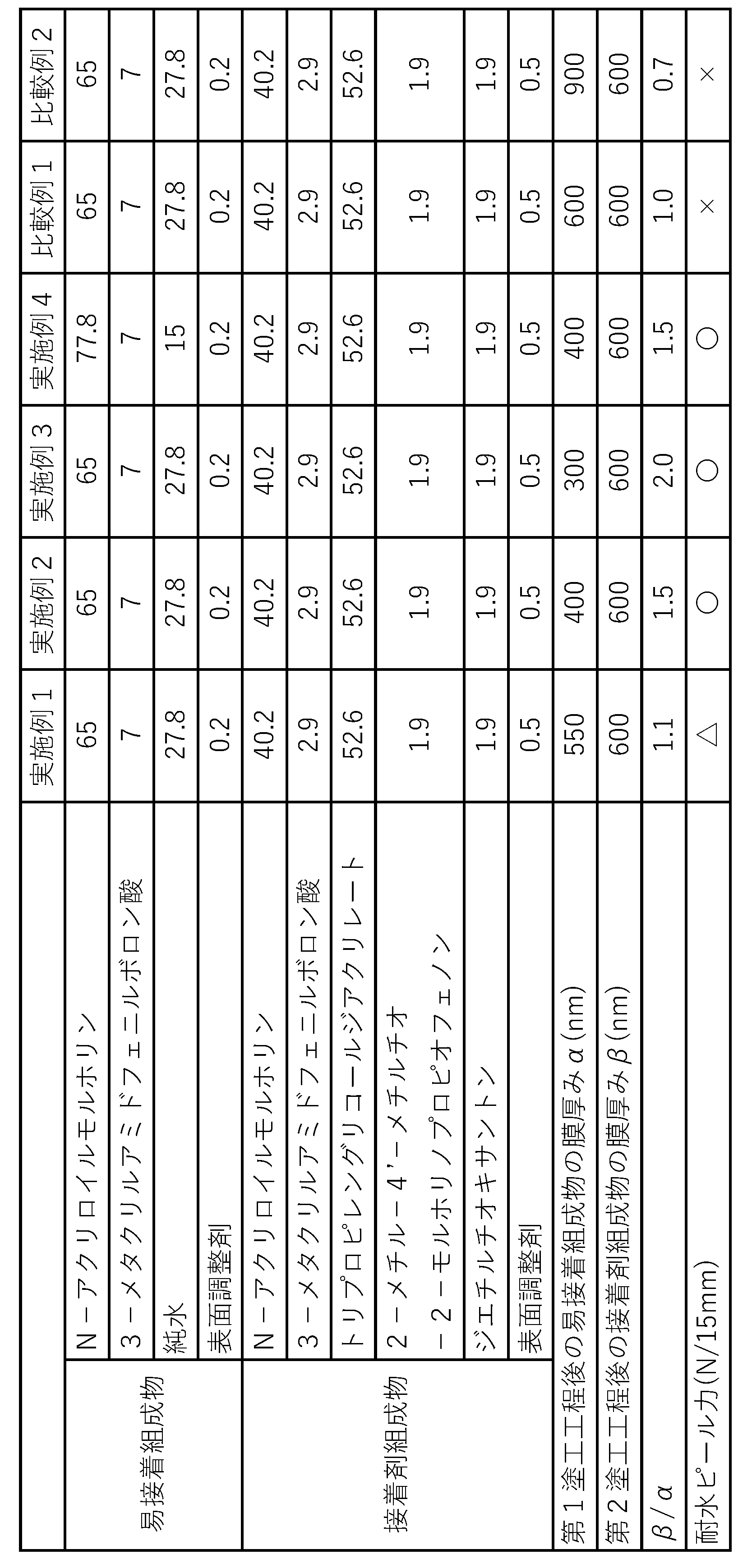
Claims (7)
- 接着剤層を介して、少なくとも第1光学フィルムおよび第2光学フィルムが積層された積層光学フィルムの製造方法であって、
前記第1光学フィルムを搬送しながら、前記第1光学フィルムの貼合面に少なくとも下記一般式(1):

前記第2光学フィルムを搬送しながら、前記第2光学フィルムの貼合面に少なくとも硬化性成分および重合開始剤を含有する接着剤組成物を塗工する第2塗工工程と、
前記第1光学フィルムおよび前記第2光学フィルムを貼り合わせる貼合工程と、
前記第1光学フィルム面側または前記第2光学フィルム面側から活性エネルギー線を照射して、少なくとも前記接着剤組成物を硬化させることにより形成された前記接着剤層を介して、前記第1光学フィルムおよび前記第2光学フィルムを接着させる接着工程とを含み、
前記易接着組成物中の前記水の含有量が40質量%以下であり、
前記第1塗工工程後の前記易接着組成物の膜厚みをα、前記第2塗工工程後の前記接着剤組成物の膜厚みをβとしたとき、β>αであることを特徴とする積層光学フィルムの製造方法。 - 前記第1塗工工程と前記貼合工程との間に乾燥工程を設けない請求項1に記載の積層光学フィルムの製造方法。
- 前記第1塗工工程終了から前記貼合工程開始までの所要時間が5秒以内である請求項1に記載の積層光学フィルムの製造方法。
- 前記第1光学フィルムが偏光子である請求項1に記載の積層光学フィルムの製造方法。
- 前記第2光学フィルムが透明保護フィルムである請求項1に記載の積層光学フィルムの製造方法。
- 前記接着剤組成物が、重合性成分として下記一般式(2):
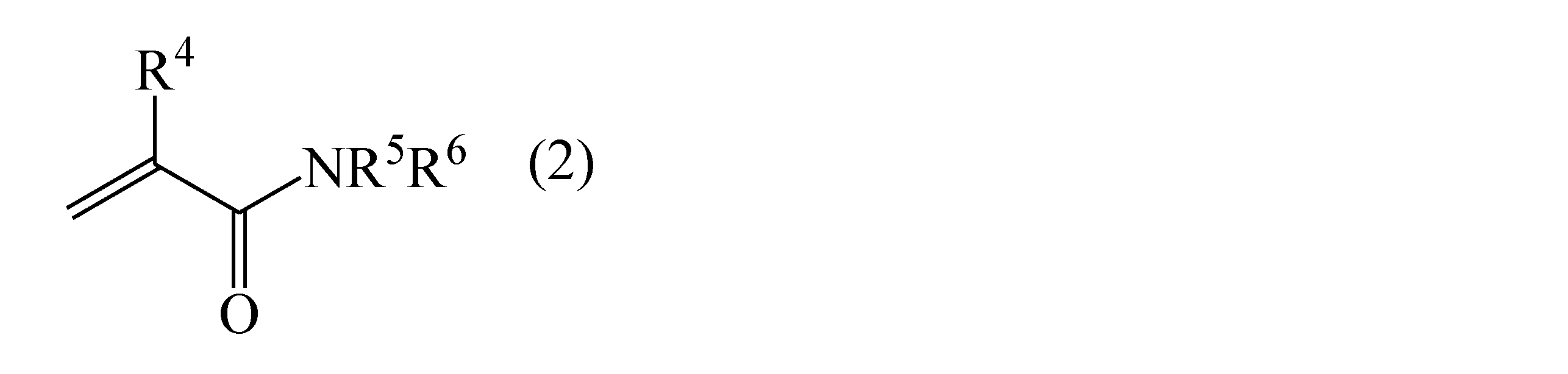
- 前記易接着組成物が、前記一般式(2)で表される化合物を含有する請求項1に記載の積層光学フィルムの製造方法。
Priority Applications (2)
| Application Number | Priority Date | Filing Date | Title |
|---|---|---|---|
| KR1020257022799A KR20260010673A (ko) | 2023-05-10 | 2024-03-12 | 적층 광학 필름의 제조 방법 |
| CN202480016819.9A CN120752562A (zh) | 2023-05-10 | 2024-03-12 | 层叠光学膜的制造方法 |
Applications Claiming Priority (2)
| Application Number | Priority Date | Filing Date | Title |
|---|---|---|---|
| JP2023077628A JP2024162277A (ja) | 2023-05-10 | 2023-05-10 | 積層光学フィルムの製造方法 |
| JP2023-077628 | 2023-05-10 |
Publications (1)
| Publication Number | Publication Date |
|---|---|
| WO2024232159A1 true WO2024232159A1 (ja) | 2024-11-14 |
Family
ID=93431534
Family Applications (1)
| Application Number | Title | Priority Date | Filing Date |
|---|---|---|---|
| PCT/JP2024/009464 Ceased WO2024232159A1 (ja) | 2023-05-10 | 2024-03-12 | 積層光学フィルムの製造方法 |
Country Status (5)
| Country | Link |
|---|---|
| JP (1) | JP2024162277A (ja) |
| KR (1) | KR20260010673A (ja) |
| CN (1) | CN120752562A (ja) |
| TW (1) | TW202514160A (ja) |
| WO (1) | WO2024232159A1 (ja) |
Families Citing this family (2)
| Publication number | Priority date | Publication date | Assignee | Title |
|---|---|---|---|---|
| JP2026092785A (ja) * | 2024-11-27 | 2026-06-08 | 日東電工株式会社 | 偏光フィルム |
| JP2026092784A (ja) * | 2024-11-27 | 2026-06-08 | 日東電工株式会社 | 偏光フィルムの製造方法 |
Citations (5)
| Publication number | Priority date | Publication date | Assignee | Title |
|---|---|---|---|---|
| KR20150052777A (ko) * | 2013-11-06 | 2015-05-14 | 동우 화인켐 주식회사 | 편광자의 제조방법 |
| WO2020196625A1 (ja) * | 2019-03-28 | 2020-10-01 | 日東電工株式会社 | 偏光フィルムの製造方法 |
| WO2020196618A1 (ja) * | 2019-03-28 | 2020-10-01 | 日東電工株式会社 | 偏光フィルムの製造方法 |
| WO2021095304A1 (ja) * | 2019-11-13 | 2021-05-20 | 日東電工株式会社 | 積層偏光フィルムの製造方法 |
| WO2021141037A1 (ja) * | 2020-01-10 | 2021-07-15 | 日東電工株式会社 | 偏光フィルムの製造方法 |
-
2023
- 2023-05-10 JP JP2023077628A patent/JP2024162277A/ja active Pending
-
2024
- 2024-03-12 KR KR1020257022799A patent/KR20260010673A/ko active Pending
- 2024-03-12 CN CN202480016819.9A patent/CN120752562A/zh active Pending
- 2024-03-12 WO PCT/JP2024/009464 patent/WO2024232159A1/ja not_active Ceased
- 2024-03-14 TW TW113109466A patent/TW202514160A/zh unknown
Patent Citations (5)
| Publication number | Priority date | Publication date | Assignee | Title |
|---|---|---|---|---|
| KR20150052777A (ko) * | 2013-11-06 | 2015-05-14 | 동우 화인켐 주식회사 | 편광자의 제조방법 |
| WO2020196625A1 (ja) * | 2019-03-28 | 2020-10-01 | 日東電工株式会社 | 偏光フィルムの製造方法 |
| WO2020196618A1 (ja) * | 2019-03-28 | 2020-10-01 | 日東電工株式会社 | 偏光フィルムの製造方法 |
| WO2021095304A1 (ja) * | 2019-11-13 | 2021-05-20 | 日東電工株式会社 | 積層偏光フィルムの製造方法 |
| WO2021141037A1 (ja) * | 2020-01-10 | 2021-07-15 | 日東電工株式会社 | 偏光フィルムの製造方法 |
Also Published As
| Publication number | Publication date |
|---|---|
| CN120752562A (zh) | 2025-10-03 |
| TW202514160A (zh) | 2025-04-01 |
| JP2024162277A (ja) | 2024-11-21 |
| KR20260010673A (ko) | 2026-01-21 |
Similar Documents
| Publication | Publication Date | Title |
|---|---|---|
| JP7265882B2 (ja) | 偏光フィルムの製造方法、易接着層付偏光子、偏光フィルム、光学フィルム、および画像表示装置 | |
| WO2016143435A1 (ja) | 架橋剤および硬化性樹脂組成物、偏光フィルムおよびその製造方法、光学フィルムならびに画像表示装置 | |
| KR102874576B1 (ko) | 편광 필름의 제조 방법 | |
| JP2024083675A (ja) | 積層光学フィルムおよび画像表示装置 | |
| KR20260010673A (ko) | 적층 광학 필름의 제조 방법 | |
| CN112334799B (zh) | 起偏镜、偏振膜、光学膜、以及图像显示装置 | |
| JP7219137B2 (ja) | 偏光フィルムの製造方法 | |
| KR102909325B1 (ko) | 편광 필름의 제조 방법 | |
| WO2020039895A1 (ja) | 偏光子、偏光フィルム、光学フィルム、ならびに画像表示装置 | |
| JP7213037B2 (ja) | 偏光子、偏光フィルム、光学フィルム、ならびに画像表示装置 | |
| WO2024247412A1 (ja) | 偏光フィルムおよびその製造方法 | |
| WO2024127733A1 (ja) | 硬化性組成物、偏光フィルム、光学フィルムおよび画像表示装置 | |
| JP2024173362A (ja) | 積層光学フィルムの製造方法 | |
| WO2024127722A1 (ja) | 硬化性樹脂組成物、偏光フィルム、積層光学フィルムおよび画像表示装置 | |
| JP2024173266A (ja) | 積層光学フィルムおよび積層光学フィルムの製造方法 | |
| WO2024127721A1 (ja) | 硬化性樹脂組成物、偏光フィルム、積層光学フィルムおよび画像表示装置 | |
| JP2024173239A (ja) | 積層光学フィルム用接着剤組成物および積層光学フィルム | |
| WO2020039899A1 (ja) | 偏光子、偏光フィルム、光学フィルム、ならびに画像表示装置 |
Legal Events
| Date | Code | Title | Description |
|---|---|---|---|
| 121 | Ep: the epo has been informed by wipo that ep was designated in this application |
Ref document number: 24803274 Country of ref document: EP Kind code of ref document: A1 |
|
| WWE | Wipo information: entry into national phase |
Ref document number: 202480016819.9 Country of ref document: CN |
|
| WWP | Wipo information: published in national office |
Ref document number: 202480016819.9 Country of ref document: CN |
|
| NENP | Non-entry into the national phase |
Ref country code: DE |
|
| 122 | Ep: pct application non-entry in european phase |
Ref document number: 24803274 Country of ref document: EP Kind code of ref document: A1 |