WO2024232158A1 - 情報処理装置、情報処理方法およびプログラム - Google Patents
情報処理装置、情報処理方法およびプログラム Download PDFInfo
- Publication number
- WO2024232158A1 WO2024232158A1 PCT/JP2024/009332 JP2024009332W WO2024232158A1 WO 2024232158 A1 WO2024232158 A1 WO 2024232158A1 JP 2024009332 W JP2024009332 W JP 2024009332W WO 2024232158 A1 WO2024232158 A1 WO 2024232158A1
- Authority
- WO
- WIPO (PCT)
- Prior art keywords
- information
- departure
- passenger
- user
- guidance information
- Prior art date
- Legal status (The legal status is an assumption and is not a legal conclusion. Google has not performed a legal analysis and makes no representation as to the accuracy of the status listed.)
- Ceased
Links
Images













Classifications
-
- G—PHYSICS
- G01—MEASURING; TESTING
- G01C—MEASURING DISTANCES, LEVELS OR BEARINGS; SURVEYING; NAVIGATION; GYROSCOPIC INSTRUMENTS; PHOTOGRAMMETRY OR VIDEOGRAMMETRY
- G01C21/00—Navigation; Navigational instruments not provided for in groups G01C1/00 - G01C19/00
- G01C21/26—Navigation; Navigational instruments not provided for in groups G01C1/00 - G01C19/00 specially adapted for navigation in a road network
- G01C21/34—Route searching; Route guidance
- G01C21/3407—Route searching; Route guidance specially adapted for specific applications
- G01C21/3423—Multimodal routing
-
- G—PHYSICS
- G01—MEASURING; TESTING
- G01C—MEASURING DISTANCES, LEVELS OR BEARINGS; SURVEYING; NAVIGATION; GYROSCOPIC INSTRUMENTS; PHOTOGRAMMETRY OR VIDEOGRAMMETRY
- G01C21/00—Navigation; Navigational instruments not provided for in groups G01C1/00 - G01C19/00
- G01C21/26—Navigation; Navigational instruments not provided for in groups G01C1/00 - G01C19/00 specially adapted for navigation in a road network
- G01C21/34—Route searching; Route guidance
- G01C21/3407—Route searching; Route guidance specially adapted for specific applications
- G01C21/3415—Dynamic re-routing, e.g. recalculating the route when the user deviates from calculated route or after detecting real-time traffic data or accidents
-
- G—PHYSICS
- G01—MEASURING; TESTING
- G01C—MEASURING DISTANCES, LEVELS OR BEARINGS; SURVEYING; NAVIGATION; GYROSCOPIC INSTRUMENTS; PHOTOGRAMMETRY OR VIDEOGRAMMETRY
- G01C21/00—Navigation; Navigational instruments not provided for in groups G01C1/00 - G01C19/00
- G01C21/26—Navigation; Navigational instruments not provided for in groups G01C1/00 - G01C19/00 specially adapted for navigation in a road network
- G01C21/34—Route searching; Route guidance
- G01C21/3407—Route searching; Route guidance specially adapted for specific applications
- G01C21/343—Calculating itineraries
-
- G—PHYSICS
- G01—MEASURING; TESTING
- G01C—MEASURING DISTANCES, LEVELS OR BEARINGS; SURVEYING; NAVIGATION; GYROSCOPIC INSTRUMENTS; PHOTOGRAMMETRY OR VIDEOGRAMMETRY
- G01C21/00—Navigation; Navigational instruments not provided for in groups G01C1/00 - G01C19/00
- G01C21/26—Navigation; Navigational instruments not provided for in groups G01C1/00 - G01C19/00 specially adapted for navigation in a road network
- G01C21/34—Route searching; Route guidance
- G01C21/36—Input/output arrangements for on-board computers
-
- G—PHYSICS
- G01—MEASURING; TESTING
- G01C—MEASURING DISTANCES, LEVELS OR BEARINGS; SURVEYING; NAVIGATION; GYROSCOPIC INSTRUMENTS; PHOTOGRAMMETRY OR VIDEOGRAMMETRY
- G01C21/00—Navigation; Navigational instruments not provided for in groups G01C1/00 - G01C19/00
- G01C21/26—Navigation; Navigational instruments not provided for in groups G01C1/00 - G01C19/00 specially adapted for navigation in a road network
- G01C21/34—Route searching; Route guidance
- G01C21/36—Input/output arrangements for on-board computers
- G01C21/3626—Details of the output of route guidance instructions
- G01C21/3655—Timing of guidance instructions
-
- G—PHYSICS
- G01—MEASURING; TESTING
- G01C—MEASURING DISTANCES, LEVELS OR BEARINGS; SURVEYING; NAVIGATION; GYROSCOPIC INSTRUMENTS; PHOTOGRAMMETRY OR VIDEOGRAMMETRY
- G01C21/00—Navigation; Navigational instruments not provided for in groups G01C1/00 - G01C19/00
- G01C21/26—Navigation; Navigational instruments not provided for in groups G01C1/00 - G01C19/00 specially adapted for navigation in a road network
- G01C21/34—Route searching; Route guidance
- G01C21/36—Input/output arrangements for on-board computers
- G01C21/3667—Display of a road map
-
- G—PHYSICS
- G01—MEASURING; TESTING
- G01C—MEASURING DISTANCES, LEVELS OR BEARINGS; SURVEYING; NAVIGATION; GYROSCOPIC INSTRUMENTS; PHOTOGRAMMETRY OR VIDEOGRAMMETRY
- G01C21/00—Navigation; Navigational instruments not provided for in groups G01C1/00 - G01C19/00
- G01C21/26—Navigation; Navigational instruments not provided for in groups G01C1/00 - G01C19/00 specially adapted for navigation in a road network
- G01C21/34—Route searching; Route guidance
- G01C21/36—Input/output arrangements for on-board computers
- G01C21/3667—Display of a road map
- G01C21/3676—Overview of the route on the road map
-
- G—PHYSICS
- G06—COMPUTING OR CALCULATING; COUNTING
- G06Q—INFORMATION AND COMMUNICATION TECHNOLOGY [ICT] SPECIALLY ADAPTED FOR ADMINISTRATIVE, COMMERCIAL, FINANCIAL, MANAGERIAL OR SUPERVISORY PURPOSES; SYSTEMS OR METHODS SPECIALLY ADAPTED FOR ADMINISTRATIVE, COMMERCIAL, FINANCIAL, MANAGERIAL OR SUPERVISORY PURPOSES, NOT OTHERWISE PROVIDED FOR
- G06Q10/00—Administration; Management
- G06Q10/04—Forecasting or optimisation specially adapted for administrative or management purposes, e.g. linear programming or "cutting stock problem"
- G06Q10/047—Optimisation of routes or paths, e.g. travelling salesman problem
-
- G—PHYSICS
- G06—COMPUTING OR CALCULATING; COUNTING
- G06Q—INFORMATION AND COMMUNICATION TECHNOLOGY [ICT] SPECIALLY ADAPTED FOR ADMINISTRATIVE, COMMERCIAL, FINANCIAL, MANAGERIAL OR SUPERVISORY PURPOSES; SYSTEMS OR METHODS SPECIALLY ADAPTED FOR ADMINISTRATIVE, COMMERCIAL, FINANCIAL, MANAGERIAL OR SUPERVISORY PURPOSES, NOT OTHERWISE PROVIDED FOR
- G06Q50/00—Information and communication technology [ICT] specially adapted for implementation of business processes of specific business sectors, e.g. utilities or tourism
- G06Q50/40—Business processes related to the transportation industry
-
- G—PHYSICS
- G08—SIGNALLING
- G08G—TRAFFIC CONTROL SYSTEMS
- G08G1/00—Traffic control systems for road vehicles
- G08G1/123—Traffic control systems for road vehicles indicating the position of vehicles, e.g. scheduled vehicles; Managing passenger vehicles circulating according to a fixed timetable, e.g. buses, trains, trams
Definitions
- the present invention relates to an information processing device, an information processing method, and a program.
- multimodal route search which searches for a route that combines multiple means of transportation
- a technology is known that suggests a route that uses the most suitable means of transportation depending on the weather along the route (see, for example, Patent Document 1).
- a passenger in a vehicle is transferring to a scheduled transportation service, and the passenger is able to obtain guidance information for the transfer in advance while on board, and in this case, if the passenger is able to obtain guidance information in advance regarding the passenger's possible actions when transferring based on the time difference between when the vehicle arrives at the scheduled transportation service's departure point and when the scheduled transportation service departs, the passenger can use this guidance information to effectively utilize the time between when the vehicle arrives at the scheduled transportation service's departure point and when the scheduled transportation service departs.
- the above-mentioned known multimodal route search technology does not suggest anything about this.
- an information processing device comprising one or more processors, The one or more processors notifying a terminal for notifying information to a passenger of the vehicle of guidance information for a transfer to a scheduled transportation facility that the passenger plans to board;
- the information processing device is provided, characterized in that the guidance information includes guidance information on possible actions of passengers when transferring depending on the time difference between the arrival of a vehicle at the departure/arrival point of the scheduled transportation facility that the passengers are scheduled to board and the departure of the scheduled transportation facility that the passengers are scheduled to board.
- an information processing method for processing information using one or more processors comprising the steps of: notifying a terminal for notifying information to a passenger of the vehicle of guidance information for a transfer to a scheduled transportation facility that the passenger plans to board;
- the information processing method is characterized in that the guidance information includes guidance information on possible actions of passengers when transferring depending on the time difference between the arrival of a vehicle at the departure/arrival point of the scheduled transportation facility that the passengers are scheduled to board and the departure of the scheduled transportation facility that the passengers are scheduled to board.
- a program for causing a computer to function so as to notify a terminal for notifying a passenger of information of guidance information for a transfer to a scheduled transportation facility that the passenger plans to board comprising:
- the guidance information provided is a program including guidance information on possible actions of passengers when transferring depending on the time difference between the arrival of a vehicle at the departure point of the scheduled transportation facility that the passengers are scheduled to board and the departure of the scheduled transportation facility that the passengers are scheduled to board.
- FIG. 1 is an overall view of an information processing system.
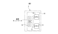
- FIG. 2 is a diagram illustrating the information processing server shown in FIG.
- FIG. 3 is a diagram illustrating the vehicle dispatch management server shown in FIG.
- FIG. 4 is a diagram illustrating an autonomous taxi.
- FIG. 5 is a functional configuration diagram of the autonomous driving taxi shown in FIG. 4.
- FIG. 6 is a diagram showing a basic flow of information processing in the information processing system.
- FIG. 7 is a diagram showing an input procedure to a terminal.
- FIG. 8 is a diagram showing a route selection procedure at a terminal.
- FIG. 9 is a flow chart for performing information processing.
- FIG. 10 is a flow chart for performing information processing.
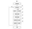
- FIG. 11 is a flowchart for performing vehicle allocation management.
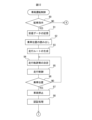
- FIG. 12 is a flowchart for controlling the driving of an autonomous driving taxi.
- FIG. 13 is a flowchart for controlling the driving of an autonomous driving taxi.
- FIG. 14 is a flowchart for controlling the driving of an autonomous driving taxi.
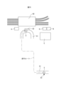
- FIG. 15 is a diagram showing a schematic representation of a road map.
- FIG. 16 is a diagram showing an additional flow of information processing that is added to the basic flow of information processing in the information processing system.
- FIG. 17 is a diagram showing a list of types of guidance information.
- FIG. 18 is a diagram showing an example of a guidance display on the display screen of the in-vehicle display device.
- FIG. 19 is a diagram showing an example of a guidance display on the display screen of the in-vehicle display device.
- FIG. 20 is a diagram showing an example of a guidance display on the display screen of the in-vehicle display device.
- FIG. 21 is a diagram showing a list of types of guidance information.
- FIG. 22 is a diagram showing a list of guidance information.
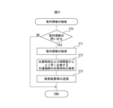
- FIG. 23 is a flowchart for executing the guidance information display process.
- FIG. 24 is a flowchart for executing the guidance information display process.
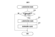
- FIG. 25 is a flow chart for searching for departure times and the like.
- FIG. 26 is a flowchart for executing a process for determining the type of guidance information.
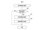
- FIG. 27 is a flow chart for searching for guidance information.
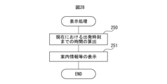
- FIG. 28 is a flowchart for executing the display process.
- FIG. 29 is a diagram showing a list of the first reference values and the second reference values.
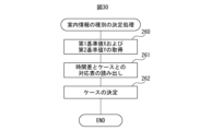
- FIG. 30 is a flowchart for executing a process for determining the type of guidance information.
- FIG. 31 is a flow chart for searching for guidance information.
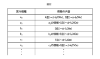
- FIG. 32 is a diagram showing a list of contents of the guidance information.
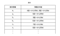
- FIG. 33 is a diagram showing a list of contents of the guidance information.
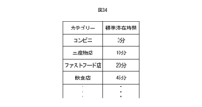
- FIG. 34 is a diagram showing a list of standard stay times by category.
- FIG. 35 is a diagram showing a list of targets of guidance information.
- FIG. 36 is a flow chart for searching for guidance information.
- the present invention relates to information processing technology for providing a moving person with guidance information when switching from a vehicle to a scheduled transportation facility in such a case.
- manually-driven vehicles, automatically-driven vehicles, private cars, commercial vehicles including taxis, etc. correspond to the vehicles to which the present invention applies
- railways such as trains, monorails, buses, and airplanes correspond to the scheduled transportation facilities to which the present invention applies.
- the present invention can be applied to manually-driven vehicles other than an automatically-driven taxi, automatically-driven vehicles, private cars, commercial vehicles including taxis, etc., and can be applied to monorails, buses, and airplanes other than railways.
- FIG. 1 shows an overall diagram of an information processing system suitable for implementing the information processing technology according to the present invention.
- 1 indicates a communication network
- 2 indicates a base station of the communication network
- 3 indicates an information processing server managed by a route search service provider or the like
- 4 indicates a dispatch management server managed by an autonomous taxi provider or the like and providing an autonomous taxi dispatch service
- 5 indicates an autonomous taxi
- 6 indicates a terminal owned by a user who uses the dispatch service of autonomous taxi 5.
- terminal 6 is depicted as a mobile terminal in FIG. 1, terminal 6 is not limited to a mobile terminal and may be a stationary terminal.
- information processing server 3 and dispatch management server 4 may be configured from the same server equipped with the functions of information processing server 3 and dispatch management server 4.
- FIG. 2 shows the information processing server 3 shown in FIG. 1.
- an electronic control unit 10 is provided within the information processing server 3.
- This electronic control unit 10 is made up of a digital computer, and includes a CPU (microprocessor) 12, memory 13 consisting of ROM and RAM, and input/output ports 14, which are connected to each other by a bidirectional bus 11.
- This electronic control unit 10 is connected to the communication network 1.
- Fig. 3 shows the vehicle dispatch management server 4 shown in Fig. 1.
- an electronic control unit 15 is provided within the vehicle dispatch management server 4.
- This electronic control unit 15 is made up of a digital computer and includes a CPU (microprocessor) 17, memory 18 consisting of ROM and RAM, and input/output ports 19, which are connected to each other by a bidirectional bus 16.
- This electronic control unit 15 is connected to the communication network 1.
- FIG. 4 shows an example of an autonomous taxi 5 in a schematic form.
- 20 indicates a vehicle drive unit for applying a driving force to the drive wheels of the autonomous taxi
- 21 indicates a braking device for braking the autonomous taxi
- 22 indicates a steering device for steering the autonomous taxi
- 23 indicates an electronic control unit mounted in the autonomous taxi 5.
- the electronic control unit 23 is made up of a digital computer and includes a CPU (microprocessor) 25, memory 26 consisting of ROM and RAM, and input/output ports 27, all connected to each other by a bidirectional bus 24.
- a CPU microprocessor
- the vehicle drive unit 20 is made up of an electric motor driven by a secondary battery or an electric motor driven by a fuel cell, and the drive wheels are driven and controlled by these electric motors in accordance with the output signal of the electronic control unit 23.
- the braking control of the autonomous taxi 5 is performed by the braking device 21 according to the output signal of the electronic control unit 23
- the steering control of the autonomous taxi 5 is performed by the steering device 22 according to the output signal of the electronic control unit 23.
- this electronic control unit 23 can be composed of one electronic control unit or multiple electronic control units.
- the autonomous taxi 5 is equipped with various sensors 28 necessary for the autonomous taxi 5 to perform autonomous driving, namely, sensors that detect the state of the autonomous taxi 5 and surrounding detection sensors that detect the surroundings of the autonomous taxi 5.
- sensors that detect the state of the autonomous taxi 5 and surrounding detection sensors that detect the surroundings of the autonomous taxi 5 include on-board cameras that photograph the front, sides, and rear of the autonomous taxi 5, LIDAR, radar, etc.
- the autonomous taxi 5 is equipped with a GNSS (Global Navigation Satellite System) receiving device 29, a map data storage device 30, a navigation device 31, and a display device 32 equipped with a display screen.
- GNSS Global Navigation Satellite System
- the GNSS receiver 29 can detect the current position (e.g., latitude and longitude) of the autonomous taxi 5 based on information obtained from multiple artificial satellites. Therefore, the current position of the autonomous taxi 5 can be obtained by this GNSS receiver 29.
- a GPS receiver is used as the GNSS receiver 29.
- the map data storage device 30 stores map data and the like necessary for the autonomous taxi 5 to perform autonomous driving.
- These various sensors 28, GNSS receiver 29, map data storage device 30, navigation device 31, and display device 32 are connected to the electronic control unit 23.
- the autonomous taxi 5 is equipped with a communication device 33 for communicating with the information processing server 3 and the vehicle dispatch management server 4 via the base station 2 and the communication network 1.
- terminal 6 owned by a user who uses the ride-hailing service is configured to be able to communicate with information processing server 3, vehicle dispatch management server 4, and autonomous taxi 5 via base station 2 and communication network 1.
- information processing server 3, vehicle dispatch management server 4, autonomous taxi 5, and terminal 6 can communicate with each other via communication network 1.
- communication device 33 and terminal 6 of autonomous taxi 5 each have a short-range wireless communication function, and communication device 33 and terminal 6 of autonomous taxi 5 are configured to be able to communicate with each other by means of these short-range wireless communication functions.
- FIG. 6 shows the interactions between the information processing server 3, the vehicle dispatch management server 4, the autonomous taxi 5, and the terminal 6.
- FIG. 6 also shows a case where a travel route is selected in which, after boarding the autonomous taxi 5, a transfer to a scheduled train is selected.
- a user using a vehicle dispatch service hereinafter simply referred to as a user inputs the departure point, departure time, destination, desired arrival time at the destination, etc. into the terminal 6 using a travel route search app, and makes a travel route search request.
- the information processing server 3 When the information processing server 3 receives this travel route search request in (2), in (3), the information processing server 3 searches for a travel route that satisfies the request based on the received departure point, departure time, destination, desired arrival time at the destination, etc. Next, in (4), the information processing server 3 transmits the travel route search results to the terminal 6. When the terminal 6 receives the travel route search results in (5), in (6), the user selects the desired travel route from among the multiple searched travel routes on the display screen of the terminal 6 using a travel route search app.
- search results for the travel route in (4) do not include a travel route that involves a transfer from the autonomous taxi 5 to a scheduled train.
- the information processing flow shown in FIG. 6 explains a case where the search results for the travel route in (4) include a travel route that involves a transfer from the autonomous taxi 5 to a scheduled train, and further, in (6), a travel route that involves a transfer from the autonomous taxi 5 to a scheduled train is selected as the desired travel route.
- a travel route involving a transfer from an autonomous taxi 5 to a scheduled train is selected, in (7), the user uses a vehicle dispatch reservation app to register desired vehicle dispatch details consisting of a desired boarding location, desired boarding time, and desired disembarking location of the autonomous taxi 5 on the display screen of the terminal 6.
- desired vehicle dispatch details consisting of a desired boarding location, desired boarding time, and desired disembarking location of the autonomous taxi 5 on the display screen of the terminal 6.
- a notice of a vehicle dispatch reservation is sent from the terminal 6 to the information processing server 3 together with the registered desired vehicle dispatch details and the user's desired travel route.
- a vehicle dispatch request is sent from the information processing server 3 to the vehicle dispatch management server 4.
- This dispatch request includes the user's desired travel route, information about a railway where a transfer is planned on the user's desired travel route, the desired dispatch content consisting of the desired boarding position, desired boarding time, and desired disembarking position of the autonomous taxi 5, and a user ID for identifying the user.
- this dispatch request may include the user's departure point, departure time, destination, and desired arrival time at the destination received by the information processing server 3 in (2).
- the dispatch management server 4 searches for an autonomous taxi 5 that can be dispatched to the user's desired boarding location at the user's desired boarding time from among the autonomous taxis 5 located near the user's desired boarding location, and selects the autonomous taxi 5 to be dispatched.
- the search can include vacant autonomous taxis 5, and can also include autonomous taxis 5 that are scheduled to become vacant near the user's desired boarding time based on the reservation information.
- a dispatch instruction is transmitted from the dispatch management server 4 to the autonomous taxi 5 selected for dispatch, together with the user's desired travel route, information about a railway to which a transfer is scheduled to be made on the user's desired travel route, desired dispatch details such as the boarding location, disembarking location, and boarding time of the autonomous taxi 5, and the user ID.
- This authentication processing is performed, for example, by comparing the user ID stored in the memory 26 of the autonomous taxi 5 at the time of the dispatch request with the user ID stored in the terminal 6 of the user who made the dispatch request, and when these user IDs match, the user who possesses the terminal 6 is authenticated as the user who made the dispatch request.
- various known authentication processes such as face recognition, are known as user authentication processes, and these known authentication processes can be used as the authentication process in (15).
- the information processing server 3 is configured to be able to communicate with the dispatch management server 4, the autonomous taxi 5, and the terminal 6 via the communication network 1.
- the information processing server 3 has a railway information receiving unit that can receive railway operation information and railway delay information in real time from the railway operator via the communication network 1.
- the information processing server 3 also has a search request receiving unit that receives a search request for a travel route from the user's terminal 6 along with the departure point, departure time, destination, desired arrival time at the destination, etc.
- the information processing server 3 also has a travel route search unit that can search for multiple travel routes, including at least a multimodal travel route using the autonomous taxi 5 and a railway, based on the departure point, departure time, destination, desired arrival time at the destination, etc. received in the search request receiving unit.
- the information processing server 3 is equipped with a search result transmission unit for transmitting the multiple travel routes searched by the travel route search unit to the user's terminal 6.
- the information processing server 3 is also equipped with a dispatch reservation receiving unit for receiving from the user's terminal 6 the desired travel route of the user, the desired dispatch content consisting of the desired boarding position, desired boarding time, and desired drop-off position of the autonomous driving taxi 5, and the fact that a dispatch reservation has been made.
- the information processing server 3 also acquires information on the user's desired travel route, the desired dispatch content such as the boarding position, drop-off position, and boarding time of the autonomous driving taxi 5 used by the user on the user's desired travel route, and the railway to which a transfer is scheduled on the user's desired travel route, and the information processing server 3 is equipped with a dispatch request transmission unit for transmitting a dispatch request including the acquired desired travel route of the user, the desired dispatch content, and information on the railway to the dispatch management server 4.
- the information processing server 3 is also equipped with an information provision unit for providing the user with various information other than the multiple travel routes searched.
- the vehicle dispatch management server 4 is configured to be able to communicate with the information processing server 3, the autonomous taxis 5, and the terminals 6 via the communication network 1.
- the vehicle dispatch management server 4 is equipped with a dispatch request receiving unit for receiving information from the information processing server 3 on the user's desired travel route, the boarding position, disembarking position, and boarding time of the autonomous taxi 5 used by the user, and the desired dispatch content, and information on the railway to which the transfer is scheduled.
- the vehicle dispatch management server 4 also has a vehicle search unit for searching for an autonomous taxi 5 that can be dispatched to the user's desired boarding position at the user's desired boarding time from among the autonomous taxis 5 located near the user's desired boarding position, and selecting the autonomous taxi 5 to be dispatched. Furthermore, the vehicle dispatch management server 4 is equipped with a dispatch instruction transmitting unit for transmitting a dispatch instruction to the autonomous taxi 5 selected for dispatch together with information on the user's desired travel route, the boarding position, disembarking position, and boarding time of the autonomous taxi 5 used by the user, and the desired dispatch content, and information on the railway to which the transfer is scheduled.
- the terminal 6 is equipped with a communication unit for communicating with the information processing server 3, the dispatch management server 4, and the autonomous driving taxi 5 via the communication network 1.
- the terminal 6 is also equipped with a current position acquisition unit, for example, consisting of a GPS receiver, capable of detecting the current position (for example, latitude and longitude) of the terminal 6.
- the terminal 6 also has a display screen.
- the terminal 6 is capable of inputting the departure point, departure time, destination, desired arrival time at the destination, etc., on the display screen of the terminal 6 using a travel route search app, and requesting a search for a travel route.
- the terminal 6 is also configured to be capable of displaying multiple travel routes searched for in the information processing server 3 on the display screen of the terminal 6.
- the terminal 6 is capable of selecting the user's desired travel route from the multiple travel routes searched for in the information processing server 3 on the display screen of the terminal 6, and furthermore, the user can make a reservation for dispatching an autonomous driving taxi 5 on the display screen of the terminal 6.
- the autonomous taxi 5 is equipped with a travel route receiving unit 40, a travel route generating unit 41, an autonomous driving control unit 42, a communication unit 43, an authentication unit 44, an operation-related information acquisition unit 45, a display control unit 46, and a current location acquisition unit 47.
- the travel route receiving unit 40, the communication unit 43, the operation-related information acquisition unit 45, and the display control unit 46 constitute the information processing device.
- the travel route receiving unit 40 receives from the vehicle dispatch management server 4 information on the user's desired travel route, the desired dispatch details such as the boarding position, disembarking position and boarding time of the autonomous taxi 5 used by the user, and information on railways where a transfer is planned. In this case, the travel route receiving unit 40 can also receive this information from the information processing server 3.
- the driving route generating unit 41 generates, based on this information, a driving route of the autonomous taxi 5 from the current position to the boarding position desired by the user, and a driving route of the autonomous taxi 5 from the boarding position desired by the user to the disembarking position desired by the user.
- the autonomous driving control unit 42 controls the autonomous driving of the autonomous taxi 5 along the generated driving route.
- the communication unit 43 is connected to the communication device 33 and can communicate with the information processing server 3, the dispatch management server 4, and the terminal 6 through the communication device 33.
- the authentication unit 44 authenticates that a person who has boarded the autonomous taxi 5 is a user who has made a reservation to dispatch the autonomous taxi 5.
- the operation-related information acquisition unit 45 acquires railway operation-related information from the information processing server 3.
- the display control unit 46 is connected to the display device 32 having a display screen installed inside the autonomous taxi 5, and the display content of the display screen installed inside the autonomous taxi 5 is controlled by the display control unit 46.
- the current location acquisition unit 47 acquires the current location of the autonomous taxi 5 based on the reception data received by the GNSS receiving device 29.
- FIG. 7 shows an input procedure to the terminal 6 by a user.
- a travel route search input screen is displayed on the display screen of the terminal 6 using a travel route search application.
- A2 for example, a departure point is entered in a departure point entry field on the input screen.
- the departure point can also be specified on a map displayed on the display screen of the terminal 6.
- A3 a departure time is entered in a departure time entry field on the input screen.
- A4 for example, a destination is entered in a destination entry field on the input screen.
- the destination can also be specified on a map displayed on the display screen of the terminal 6.
- a desired arrival time at the destination is entered in a desired arrival time entry field on the input screen.
- a search request button displayed on the input screen is touched. When the search request button is touched, a travel route search request is transmitted to the information processing server 3 together with the input departure point, departure time, destination, and desired arrival time at the destination.
- FIG. 8 shows the route selection procedure on the terminal 6 by the user.
- B1 the search results of multiple travel routes transmitted from the information processing server 3 are displayed on the display screen of the terminal 6.
- B2 a desired travel route is selected from these multiple travel routes. Note that at this time, a case will be described in which a travel route involving a transfer from the autonomous taxi 5 to a scheduled train is selected as the desired travel route.
- the user uses a vehicle dispatch reservation app on the display screen of the terminal 6 to register the desired vehicle dispatch details consisting of the desired boarding position, desired boarding time, and desired disembarking position in the registration fields for the desired boarding position, desired boarding time, and desired disembarking position of the autonomous taxi 5, respectively.
- the desired boarding position and desired disembarking position can be registered by specifying the desired boarding position and desired disembarking position on the map displayed on the display screen of the terminal 6.
- a notification that a vehicle dispatch reservation has been made is sent from the terminal 6 to the information processing server 3 together with the registered desired vehicle dispatch details and the user's desired travel route.
- step 60 current train operation information and current train delay information are received from the train operator, and the received current train operation information and current train delay information are stored in the memory 13 of the electronic control unit 10.
- step 61 it is determined whether or not there has been a request for the current train operation information and delay information. If it is determined that there has been a request for the current train operation information and delay information, the process proceeds to step 62, where the requested information is searched for. Next, the process proceeds to step 63, where the search results for the requested information are sent to the requester. Next, the process proceeds to step 64. On the other hand, if it is determined in step 61 that there has been no request for the current train operation information and delay information, the process jumps to step 64.
- step 64 it is determined whether or not a travel route search request has been received from the terminal 6. If it is determined that a travel route search request has been received from the terminal 6, the process proceeds to step 65, where the received data, such as the user's departure point, departure time, destination, and desired arrival time at the destination, received together with the travel route search request, is stored in the memory 13 of the electronic control unit 10. Next, in step 66, a search is performed for multiple travel routes that satisfy the user's requirements. Next, in step 67, the search results for the travel routes are stored in the memory 13 of the electronic control unit 10. Next, in step 68, the search results for the travel routes are sent to the terminal 6. Next, the process proceeds to step 69. On the other hand, if it is determined in step 64 that a travel route search request has not been received from the terminal 6, the process jumps to step 69.
- step 69 it is determined whether a dispatch reservation has been received from the terminal 6 along with the desired boarding position, desired boarding time, desired disembarking position, and the user's desired travel route for the autonomous taxi 5. If it is determined that a dispatch reservation has been received from the terminal 6, the process proceeds to step 70, where the received desired boarding position, desired boarding time, desired disembarking position, and the user's desired travel route are stored in the memory 13 of the electronic control unit 10.
- a dispatch request is sent to the dispatch management server 4, including the user's desired travel route, information about a railway where a transfer is planned on the user's desired travel route, the desired boarding position, desired boarding time, and desired disembarking position for the autonomous taxi 5, and a user ID for identifying the user.
- the processing cycle is terminated.
- FIG. 11 shows a vehicle dispatch management routine executed in the electronic control unit 15 of the vehicle dispatch management server 4, and this routine is executed repeatedly. 11, first, in step 80, it is determined whether or not a dispatch request has been received from the information processing server 3. When it is determined that a dispatch request has not been received from the information processing server 3, the processing cycle is terminated.
- the processing proceeds to step 81, and the received data, such as the received user's desired travel route, information about a railway to which a transfer is scheduled on the user's desired travel route, the desired boarding position, the desired boarding time and the desired disembarking position of the autonomously driving taxi 5, and the user ID, are stored in the memory 18 of the electronic control unit 15.
- an autonomous taxi 5 that can be dispatched to the user's desired boarding location at the user's desired boarding time is searched for among the autonomous taxis 5 located near the user's desired boarding location.
- the search can include vacant autonomous taxis 5, and autonomous taxis 5 that are scheduled to become vacant near the user's desired boarding time based on the reservation information can also be included in the search.
- an autonomous taxi 5 to be dispatched is selected from the autonomous taxis 5 that are the search targets.
- step 84 a dispatch instruction is transmitted from the dispatch management server 4 to the autonomous taxi 5 selected for dispatch together with the user's desired travel route, information about a railway to which a transfer is scheduled on the user's desired travel route, desired dispatch details such as the boarding position, disembarking position, and boarding time of the autonomous taxi 5, and the user ID.
- step 85 a message indicating that the dispatch has been completed is transmitted to the terminal 6.
- 12 to 14 show a driving control routine for the autonomous taxi executed in the electronic control unit 23 of the autonomous taxi 5 selected for dispatch, and this routine is executed repeatedly. 12 to 14, first, in step 90, it is determined whether or not a dispatch instruction has been received from the dispatch management server 4. When it is determined that a dispatch instruction has not been received from the dispatch management server 4, the processing cycle is terminated.
- the process proceeds to step 91, and the received data, such as the received user's desired travel route, information about a railway to which a transfer is scheduled on the user's desired travel route, the desired boarding position, the desired boarding time and the desired disembarking position of the autonomously driven taxi 5, and the user ID, are stored in the memory 26 of the electronic control unit 23.
- step 92 the user's desired boarding position is read from memory 26.
- step 93 the navigation device 31 creates a driving route for the autonomous taxi 5 from the current position to the user's desired boarding position based on the current position of the autonomous taxi 5 acquired by the GNSS receiving device 29 and the user's desired boarding position read from memory 26.
- step 94 the driving trajectory and driving speed of the autonomous taxi 5 that does not come into contact with other vehicles or pedestrians are determined based on the detection results of sensors such as cameras, lidar, and radar that capture images of the area ahead of the autonomous taxi 5.
- step 95 driving control of the autonomous taxi 5 is performed according to the determined driving trajectory and driving speed.
- step 96 it is determined whether the autonomous taxi 5 has reached the user's desired boarding position. If it is determined that the autonomous taxi 5 has not reached the user's desired boarding position, the process returns to step 94, and the autonomous taxi 5 continues to drive autonomously. On the other hand, if it is determined in step 96 that the autonomous taxi 5 has reached the user's desired boarding position, the process proceeds to step 97, and the autonomous taxi 5 is stopped.
- step 98 a user authentication process is performed between the terminal 6 of the user who made the vehicle dispatch reservation and the autonomous taxi 5 using short-range communication.
- This authentication process is performed, for example, by comparing the user ID stored in the memory 26 of the autonomous taxi 5 at the time of the vehicle dispatch request with the user ID stored in the terminal 6 of the user who made the vehicle dispatch request, and when these user IDs match, the user who possesses the terminal 6 is authenticated as the user who made the vehicle dispatch request.
- various known authentication processes such as face authentication, are known as user authentication processes, and these known authentication processes can also be used as the authentication process in step 98.
- step 99 it is determined whether or not the user possessing the terminal 6 has been authenticated as the user who requested the dispatch in the authentication process in step 98. If the user possessing the terminal 6 has not been authenticated as the user who requested the dispatch in the authentication process, the process jumps to step 112, and a request is made to the dispatch management server 4 for instructions on the next action. At this time, the autonomous taxi 5 is, for example, autonomously driven to the desired boarding position of another user who requested the dispatch. In contrast, if the authentication process authenticates that the user possessing the terminal 6 is the user who requested the dispatch, the process proceeds to step 100, and the door of the autonomous taxi 5 is opened. When the door of the autonomous taxi 5 is opened, the user who requested the dispatch alone, or several people including the user who requested the dispatch, get into the autonomous taxi 5.
- step 101 a boarding confirmation process is performed to confirm that the user who requested the dispatch, or several people including the user who requested the dispatch, have boarded the autonomously driven taxi 5.
- This boarding confirmation process is performed by a boarding confirmation device installed in the autonomously driven taxi 5, for example, by analyzing video from a boarding confirmation camera that captures the interior of the vehicle.
- step 102 it is determined whether or not the user who requested the dispatch, or several people including the user who requested the dispatch, have boarded the autonomously driven taxi 5. If it is determined that the boarding completion has not been confirmed, the process returns to step 101, and the boarding confirmation process to confirm the boarding completion is continued. On the other hand, if it is determined in step 101 that the boarding completion has been confirmed, the process proceeds to step 103.
- step 103 the door of the autonomous taxi 5 is closed.
- step 104 a request is made for the autonomous taxi 5 to start driving.
- the request for the autonomous taxi 5 to start driving is made, for example, by the user who is in the autonomous taxi 5 touching a driving start button displayed on the display screen of the display device 32 in the autonomous taxi 5.
- step 105 the user's desired drop-off location is read from the memory 26.
- step 106 the navigation device 31 creates a driving route for the autonomous taxi 5 from the current location to the user's desired drop-off location based on the current location of the autonomous taxi 5 acquired by the GNSS receiving device 29 and the user's desired drop-off location read from the memory 26.
- step 107 the driving trajectory and driving speed of the autonomous taxi 5 that does not come into contact with other vehicles or pedestrians are determined based on the detection results of sensors such as a camera, lidar, and radar that capture images of the area in front of the autonomous taxi 5.
- step 108 driving control of the autonomous taxi 5 is performed according to the determined driving trajectory and driving speed.
- step 109 it is determined whether the autonomous taxi 5 has reached the user's desired drop-off location. If it is determined that the autonomous taxi 5 has not reached the user's desired drop-off location, the process returns to step 107, and the autonomous driving of the autonomous taxi 5 continues. On the other hand, if it is determined in step 109 that the autonomous taxi 5 has reached the user's desired drop-off location, the process proceeds to step 110, and the autonomous taxi 5 is stopped.
- a disembarking confirmation process is performed to confirm that the user, or several people including the user, have disembarked from the autonomous taxi 5.
- This disembarking confirmation process is performed by an alighting confirmation device installed in the autonomous taxi 5, for example, by analyzing video from an alighting confirmation camera that captures the interior of the vehicle.
- a request is made to the vehicle dispatch management server 4 for instructions regarding the next action.
- a travel route is a multimodal travel route that uses an autonomous taxi 5 and a scheduled transportation facility such as a railroad
- the user riding in the autonomous taxi 5, or several passengers including the user will need to transfer to a scheduled transportation facility such as a railroad after getting off the autonomous taxi 5.
- the passenger of the autonomous taxi 5 can obtain guidance information for the transfer in advance while riding in the autonomous taxi 5.
- the passenger can use this guidance information to effectively utilize the time between when the autonomous taxi 5 arrives at the departure or arrival point of the scheduled transportation facility and when the scheduled transportation facility departs.
- a passenger in an autonomous taxi 5 is able to obtain in advance, while aboard the autonomous taxi 5, guidance information regarding possible actions the passenger can take when transferring based on the time difference between when the autonomous taxi 5 arrives at the departure or arrival point of the scheduled transportation means and when the scheduled transportation means departs.
- the scheduled transportation means is a train or other railway.
- FIG. 15 illustrates an example of a road map including a train or other railroad station, i.e., a railroad station.
- 50 indicates a railroad station, i.e., a railroad station
- 51 indicates a part of a road
- 52 indicates a car boarding and disembarking area.
- A, B, C, and D indicate facilities installed around or within station 50, where A indicates a convenience store, B indicates a restaurant, C indicates a shopping center, and D indicates a fast food restaurant.
- 53 indicates the user's desired boarding position for the autonomous taxi 5.
- FIG. 15 indicates a railroad station, i.e., a railroad station
- 51 indicates a part of a road
- 52 indicates a car boarding and disembarking area.
- A, B, C, and D indicate facilities installed around or within station 50, where A indicates a convenience store, B indicates a restaurant, C indicates a shopping center, and D indicates a fast food restaurant.
- 53 indicates the user's desired boarding
- the user's desired disembarking position is car boarding and disembarking area 52, and the user who boards autonomous taxi 5 at the user's desired boarding position 53 disembarks from autonomous taxi 5 at car boarding and disembarking area 52.
- the actions that passengers can take when transferring vary depending on the time difference between when the user gets off the autonomous taxi 5 and the departure time of the train. Therefore, if the passenger can obtain guidance information regarding the actions that the passenger can take when transferring in advance while riding in the autonomous taxi 5, the passenger can fully consider the actions that the passenger can take when transferring to the train while riding in the autonomous taxi 5, and as soon as the autonomous taxi 5 arrives at the station 50, the passenger can immediately begin the action that they have decided on. As a result, the time during transfer can be used effectively. Therefore, in an embodiment of the present invention, guidance information regarding the actions that the passenger can take when transferring to the train is presented to the passenger while riding in the autonomous taxi 5.
- FIG. 16 shows an additional flow of information processing that is executed following the basic flow of information processing shown in FIG. 6. Note that, like FIG. 6, FIG. 16 shows the interactions between the information processing server 3, the dispatch management server 4, the autonomously driving taxi 5, and the terminal 6. FIG. 16 also shows the case where a travel route is selected that transfers to a train that runs on schedule after getting into the autonomously driving taxi 5.
- the time it will take for the autonomous taxi 5 to arrive at the user's desired drop-off location is estimated based on the driving route generated when a request to start driving was made in (16) of FIG. 6 and traffic information received by the autonomous taxi 5 from a traffic information center.
- an estimated arrival time when the autonomous taxi 5 will arrive at the user's desired drop-off location is estimated based on the estimated time it will take to arrive at the user's desired drop-off location and the current time.
- the information processing server 3 transmits to the autonomous taxi 5 the departure time of the train that the user plans to board, and the autonomous taxi 5 thereby obtains the departure time of the train that the user plans to board.
- This train departure time is the latest departure time, and if the train is delayed, it will be the delayed departure time.
- the time difference ⁇ t between the estimated arrival time of the autonomous taxi 5 at the user's desired drop-off location and the departure time of the train the user plans to board is calculated.
- the time difference ⁇ t from the arrival of the vehicle at the departure or arrival point of the scheduled transportation service that the passenger plans to board to the departure of the scheduled transportation service that the passenger plans to board is calculated.
- the display timing is determined for displaying guidance information on the display screen of the display device 32 of the autonomous taxi 5. This display timing is set to a predetermined time before the estimated arrival time of the autonomous taxi 5 at the user's desired drop-off location, and this predetermined time is made larger, for example, as the calculated time difference ⁇ t becomes shorter.
- the type of guidance information to be displayed on the display screen of the display device 32 of the autonomous taxi 5 is determined based on this time difference ⁇ t.
- the guidance information and the types of guidance information will be explained with reference to a specific example.
- FIG. 17 shows a list of types of guidance information
- FIG. 18 to FIG. 20 show the guidance information displayed on the display screen of the display device 32.
- the time difference ⁇ t is classified into three cases 1, 2, and 3.
- case 1 is the case where the time difference ⁇ t is the shortest, less than 10 minutes
- case 3 is the case where the time difference ⁇ t is the longest, more than 20 minutes
- case 2 is intermediate between cases 1 and 3, where the time difference ⁇ t is between 10 and 20 minutes.
- the type of guidance information is information about the boarding and disembarking locations of the transportation facility that the user plans to board.
- this boarding and disembarking location is the platform.
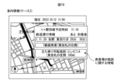
- FIG. 18 shows a specific example of guidance information displayed on the display screen of the display device 32 of the autonomous taxi 5 in case 1. In the specific example shown in FIG.
- the date and current time are displayed in the margins around the map screen on which the navigation device 31 shows the vehicle's travel route and on some blank areas on the map screen, and the destination on the vehicle's travel route and the estimated arrival time of the vehicle are displayed as "estimated arrival time at xx station", and the operation information of the transportation facility that the user plans to board (departure time, type of train (such as local, express, or limited express), and destination) are displayed as "railway operation information".
- the time difference ⁇ t between the expected arrival time of the vehicle and the departure time of the means of transport is displayed as " ⁇ minutes after arrival”
- the boarding and alighting location "Departing and alighting from platform 7 (to the right of the east ticket gate)" is displayed as information regarding the boarding and alighting location of the means of transport that the user plans to board.
- the time difference ⁇ t is 8 minutes. Therefore, as can be seen from Figure 17, this specific example corresponds to case 1, and therefore, as shown in Figure 18, information regarding the boarding and alighting locations of the means of transport that the user plans to board is displayed.
- the type of guidance information is information about the boarding and alighting locations of the transportation facility that the passenger plans to board, in addition to the information about the boarding and alighting locations of the transportation facility that the user plans to board in case 1, and information about the facilities at the departure and arrival points of the transportation facility that the passenger plans to board.
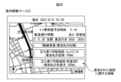
- FIG. 19 shows a specific example of guidance information displayed on the display screen of the display device 32 of the autonomous driving taxi 5 in case 2. In the specific example shown in FIG. 19, in addition to the display in case 1 shown in FIG.
- the remaining time until the departure time and the time difference ⁇ t between the vehicle's scheduled arrival time and the departure time of the transportation are displayed for the operation information of the transportation that the user plans to board, and in one specific example shown in FIG. 19, the time difference ⁇ t is 18 minutes. Therefore, as can be seen from FIG. 17, this specific example corresponds to case 2, and therefore, as shown in FIG. 19, information regarding the boarding and disembarking locations of the transportation that the user plans to board and information regarding the facilities at the departure and arrival points of the transportation that the passenger plans to board are displayed.
- the type of guidance information is information about the boarding and alighting locations of the transportation facility that the user plans to board in case 1, as well as information about facilities at the departure and arrival points that are more than those in case 2.
- FIG. 20 shows a specific example of guidance information displayed on the display screen of the display device 32 of the autonomous taxi 5 in case 3.
- information about another facility at the departure and arrival point of the transportation facility that the passenger plans to board is additionally displayed on a blank portion of a map screen showing the vehicle's driving route.
- this facility is also a facility that the passenger can stop by, and in FIG. 20, Restaurant B is displayed as the name of this facility.
- the distance from the station ticket gate to this facility i.e., Restaurant B, is also displayed.
- the remaining time until the departure time and the time difference ⁇ t between the scheduled arrival time of the vehicle and the departure time of the transportation facility are displayed for the operation information of the transportation facility that the user plans to board, and in one specific example shown in FIG. 20, the time difference ⁇ t is 28 minutes. Therefore, as can be seen from FIG. 17, this specific example corresponds to case 3, and therefore, as shown in FIG. 20, information on the boarding and alighting locations of the transportation facility that the user plans to board and information on facilities with more departure and arrival locations than in case 2 are displayed.
- case 3 since the time difference ⁇ t is larger than in case 2, there is more time until the departure time of the transportation facility compared to case 2, and therefore the facilities added in case 3 are facilities farther away from the alighting location of the autonomous driving taxi 5 compared to case 2.
- the contents of the guidance information for each type of guidance information corresponding to each of cases 1, 2, and 3 are stored in advance in the memory 13 of the electronic control unit 10 of the information processing server 3.
- the type of guidance information to be displayed on the display screen of the display device 32 of the autonomous taxi 5 is determined based on the time difference ⁇ t, that is, it is determined which of cases 1, 2, or 3 the case corresponds to.
- the information processing server 3 transmits the content of the guidance information corresponding to the determined type of guidance information, that is, the determined case number, to the autonomous taxi 5, and the autonomous taxi 5 thereby acquires the content of the guidance information corresponding to the determined type of guidance information, that is, the determined case number.
- the content of the acquired guidance information is output to the display device 32 of the autonomous taxi 5, and the guidance information as shown in FIG. 18 to FIG. 20 is displayed on the display screen of the display device 32.
- the content of the guidance information as shown in FIG. 18 to FIG. 20 can also be conveyed to passengers by voice from an in-vehicle speaker.
- FIG. 17 shows a specific example of a list of types of guidance information
- FIG. 18 to FIG. 20 show a specific example of guidance information displayed on the display screen of the display device 32.
- the time difference ⁇ t that marks the boundary between Case 1 and Case 2 and the time difference ⁇ t that marks the boundary between Case 2 and Case 3 can be set arbitrarily, and the time difference ⁇ t that marks the boundary between Case 1 and Case 2, and the time difference ⁇ t that marks the boundary between Case 2 and Case 3 are set to appropriate values depending on the situation at the departure and arrival points.
- a first reference value X and a second reference value Y are set for the time difference ⁇ t
- case 1 is a case where the time difference ⁇ t is less than the shortest first reference value X
- case 3 is a case where the time difference ⁇ t is equal to or greater than the longest second reference value Y
- case 2 is a case between case 1 and case 3, where the time difference ⁇ t is between the first reference value X and the second reference value Y.
- the type of guidance information is information about the boarding and alighting places of the transportation facility that the user plans to board, in addition to the information about the boarding and alighting places of the transportation facility that the user plans to board in case 1, and in case 3, the type of guidance information is information about facilities at the departure and arrival points of the transportation facility that the passenger plans to board in addition to the information about the boarding and alighting places of the transportation facility that the user plans to board in case 1, and information about facilities at more departure and arrival points than in case 2.
- the facility added in case 3 is a facility that is farther away from the drop-off location of the autonomous taxi 5 than in case 2.
- Fig. 22 shows a list of display contents of guidance information preset for each case 1 , 2, 3 for each departure and arrival point P1, P2, P3 ..., for example, for each station, i.e., guidance display a1, a2 , a3 , b1 , b2 , b3 , c1 , c2 , ca3 , ....
- the relationship between the first reference value X, the second reference value Y and the case number shown in Fig. 21 is stored in the memory 26 of the electronic control unit 23 of the autonomous driving taxi 5, and the display contents of the guidance information corresponding to the case number for each departure and arrival point P1, P2, P3 ... shown in Fig.
- guidance display a1 , a2 , a3 , b1 , b2 , b3 , c1 , c2 , ca3 , ... are stored in advance in the memory 13 of the electronic control unit 10 of the information processing server 3.
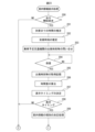
- FIGS. 23 and 24 show a guidance information display processing routine for executing the additional information processing flow shown in FIG. 16. This routine is repeatedly executed in the electronic control unit 23 of the autonomously driven taxi 5 selected for dispatch.
- step 200 after the completion of the ride in the autonomous taxi 5 of the user who requested the dispatch, it is determined whether or not a request to start driving the autonomous taxi 5 has been made.
- the processing cycle is terminated.
- the process proceeds to step 201, and the time until the autonomous taxi 5 arrives at the user's desired drop-off position is estimated based on the driving route of the autonomous taxi 5 to the user's desired drop-off position generated in step 106 of FIG. 13 showing the basic flow, and the traffic information received by the autonomous taxi 5 from the traffic information center.
- step 202 the arrival time when the autonomous taxi 5 arrives at the user's desired drop-off position is estimated based on the time until the user's desired drop-off position estimated in step 201 and the current time.
- step 203 the autonomous taxi 5 inquires of the information processing server 3 about the departure time of the train the user plans to board.
- FIG. 25 shows a search routine for departure times, etc., executed in the electronic control unit 10 of the information processing server 3 to respond to this inquiry.
- step 220 it is determined whether or not an inquiry has been received from an autonomous taxi 5.
- the process proceeds to step 221, where the departure time, boarding and alighting locations, type of train (local, express, limited express, etc.), and destination of the train that the user plans to board are searched for based on the received train operation information.
- the departure time and boarding and alighting locations of the train are the latest departure time and boarding and alighting locations.
- step 222 the search results for the departure times, etc. are transmitted from the information processing server 3 to the autonomous taxi 5.
- step 204 the process waits until the search results such as the departure time are received.
- the process proceeds to step 205, where the latest received departure time and boarding/alighting location are acquired, and the latest received departure time and boarding/alighting location are stored in the memory 26 of the electronic control unit 23 of the autonomous taxi 5.
- step 206 the time difference ⁇ t between the estimated arrival time of the autonomous taxi 5 at the user's desired alighting location and the departure time of the train the user plans to board is calculated.
- step 207 the display timing for displaying guidance information on the display screen of the display device 32 of the autonomous taxi 5 is determined.
- This display timing is, for example, a predetermined time before the estimated time until arrival at the user's desired alighting location, and this predetermined time is, for example, increased as the calculated time difference ⁇ t becomes shorter.
- step 208 it is determined whether the display timing has arrived. If it is determined that the display timing has not arrived, the processing cycle is terminated. On the other hand, if it is determined that the display timing has arrived, the process proceeds to step 209, where the type of guidance information is determined based on the time difference ⁇ t calculated in step 206.
- the routine for determining the type of guidance information is shown in FIG. 26, and this routine is executed in the electronic control unit 23 of the autonomous taxi 5.
- step 230 a list of types of guidance information shown in FIG. 21 stored in the memory 26 of the electronic control unit 23 of the autonomous taxi 5, i.e., a correspondence table between time difference ⁇ t and cases, is read out.
- step 231 it is determined which case applies depending on the time difference ⁇ t calculated in step 206.
- time difference ⁇ t is less than the first reference value, it is determined as case 1; if the time difference ⁇ t is between the first reference value X and the second reference value Y, it is determined as case 2; and if the time difference ⁇ t is equal to or greater than the second reference value Y, it is determined as case 3.
- step 210 in FIG. 24 shows a guidance information search routine executed in the electronic control unit 10 of the information processing server 3 to respond to this query.
- step 240 it is determined whether or not an inquiry from an autonomous taxi 5 has been received.
- the process proceeds to step 241, where a search is performed for guidance information corresponding to the determined case number based on the list of guidance information shown in FIG. 22 stored in the memory 13 of the electronic control unit 10 of the information processing server 3. That is, the guidance information corresponding to the departure and arrival points P1, P2, P3, etc. of the train that the user plans to board and the determined case number are searched for from among the guidance displays a1 , a2, a3 , b1 , b2 , b3, c1 , c2 , ca3 , etc. shown in the list of guidance information in FIG. 22.
- step 242 the contents of the searched guidance information are transmitted from the information processing server 3 to the autonomous taxi 5.
- step 211 the system waits until the contents of the searched guidance information are received.
- the system proceeds to step 212, where the search contents of the received guidance information are acquired, and the search contents of the received guidance information are stored in the memory 26 of the electronic control unit 23 of the autonomous taxi 5.
- step 213 a display process of the search contents of this guidance information, etc. is performed.
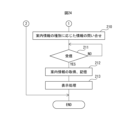
- step 250 the remaining time from the current time to the departure time of the train the user plans to board is calculated.
- step 251 the remaining time calculated in step 250, the time difference ⁇ t calculated in step 206, the estimated arrival time at the desired disembarking position calculated in step 202, the departure time of the train the user plans to board acquired in step 207, the boarding and disembarking locations, the type of train (local, express, limited express, etc.), the destination, and the contents of the guidance information acquired in step 212 are output to the display device 32 of the autonomous taxi 5, and the guidance information as shown in FIG. 18 to FIG. 20 is displayed on the display screen of the display device 32.
- the estimated arrival time at the desired disembarking location is displayed as "Scheduled arrival time at xx station”
- the departure time of the train to be boarded, the type of train (local, express, limited express, etc.), and the destination are displayed as "railway operation information”
- the remaining time until the departure time of the train to be boarded is displayed as " ⁇ minutes left”
- the time difference ⁇ t is displayed as " ⁇ minutes after arrival”.
- the boarding and disembarking location "Departure and arrival at platform 7 (to the right of the east ticket gate)" is displayed as guidance information regarding the boarding and disembarking location, and "Facility where you can stop by: Convenience store A (100 m to the left of the east ticket gate)" and “Facility where you can stop by: Restaurant B (200 m to the right of the east ticket gate)” are displayed as guidance information regarding the facility.
- the guidance information regarding the boarding and disembarking location is displayed, information regarding the way the passenger should proceed to the boarding and disembarking location, for example, a route to the boarding and disembarking location on a map displayed on the display screen of the display device 32, can also be presented.
- the electronic control unit 23 including the display device 32 constitutes a terminal that notifies the passengers of the vehicle of information.
- information about the operation of the train the passenger plans to board, and guidance information about boarding and alighting locations and facilities can also be displayed on the display screen of a terminal 6 owned by the user, for example, a mobile terminal owned by the user. Therefore, in an embodiment of the present invention, the terminal that notifies the passengers of the vehicle of information refers to both the electronic control unit 23 including the display device 32 of the autonomously driven taxi 5, and the terminal 6 owned by the user.
- the terminal that notifies the vehicle passengers of information is a terminal 6 owned by the user
- the notified information can basically only be viewed by the user alone.
- the terminal that notifies the vehicle passengers of information is an electronic control unit 23 including a display device 32
- the notified information can be viewed simultaneously by multiple passengers, including the user, through the display screen of the display device 32 installed inside the vehicle. Therefore, when the terminal that notifies the vehicle passengers of information is an electronic control unit 23 including a display device 32, as in the embodiment of the present invention, there is an advantage that information can be provided to multiple passengers simultaneously.
- an information processing device is provided with one or more processors, and the one or more processors notify a terminal that notifies information to passengers of guidance information when the passengers transfer to the scheduled regular transportation service that they plan to use, and this guidance information includes guidance information regarding possible actions of the passengers when transferring, depending on the time difference ⁇ t between the arrival of the vehicle at the departure or arrival point of the scheduled regular transportation service that the passengers plan to use and the departure of the scheduled regular transportation service that the passengers plan to use.
- the present invention also provides an information processing method that uses one or more processors to process information, and notifies a terminal that notifies information to vehicle passengers of guidance information when the passengers transfer to a scheduled transportation service that they plan to use, the guidance information including guidance information regarding possible actions the passengers can take when transferring depending on the time difference ⁇ t between the arrival of the vehicle at the departure/arrival point of the scheduled transportation service that the passengers plan to use and the departure of the scheduled transportation service that the passengers plan to use.
- a program causes a computer to function to notify a terminal that notifies information to vehicle passengers of guidance information when the passengers transfer to a scheduled transportation service that they plan to board, the guidance information including guidance information regarding possible actions of the passengers when transferring depending on the time difference ⁇ t between the arrival of the vehicle at the departure or arrival point of the scheduled transportation service that the passengers plan to board and the departure of the scheduled transportation service that the passengers plan to board.
- the timing for displaying guidance information on the display screen of the display device 32 of the autonomous taxi 5 is set to, for example, a predetermined time before the estimated time until arrival at the user's desired drop-off location, and this predetermined time is increased, for example, as the calculated time difference ⁇ t becomes shorter. That is, in an embodiment of the present invention, the timing for displaying the guidance on the terminal is determined based on the time difference ⁇ t so that the notified guidance information is displayed on the terminal before the vehicle arrives at the departure/arrival point, and in this case, the shorter the time difference ⁇ t, the earlier the display timing is made.
- the shorter the calculated time difference ⁇ t i.e., the shorter the transfer time
- the earlier the transfer preparations must be made and there is a risk of missing the planned transfer transportation facility, especially if there is a lot of luggage. Therefore, the shorter the time difference ⁇ t, the earlier the display timing is made to inform the passengers of the autonomous taxi 5 that the transfer time is short.
- Figs. 29 and 30 show modified examples in which the first reference value X and the second reference value Y are changed according to the departure and arrival points Q1, Q2, Q3, etc. of the scheduled transportation mode that the passenger plans to board.
- Fig. 29 shows a list of the first reference value X and the second reference value Y that are set for each departure and arrival point Q1, Q2, Q3, etc. according to the type of train (normal, express, limited express).
- the shock of missing a train with a long interval is greater than the shock of missing a train with a short interval, so it is normal to want to act with more leeway when taking a train with a long interval than when taking a train with a short interval. Therefore, as shown in FIG. 29, when the departure and arrival points Q1, Q2, Q3, etc. are the same, the first reference value X and the second reference value Y are set larger for express trains, which have a longer interval than ordinary trains, and the first reference value X and the second reference value Y are set larger for limited express trains, which have a longer interval than express trains, than express trains.
- the landing area sizes are Q1, Q2, Q3, and so on in Fig. 29, the first reference value X and the second reference value Y are set larger for ordinary trains, express trains, and limited express trains as the landing area size increases, as shown in Fig. 29.
- Fig. 29 shows an example of a specific time for each of the first reference values X and second reference values Y.
- the list of the first reference values X and second reference values Y shown in Fig. 29 is stored in the memory 13 of the electronic control unit 10 of the information processing server 3.
- the guidance information display processing routine shown in Figures 23 and 24, the search routine for departure times, etc. shown in Figure 25, the search routine for guidance information shown in Figure 27, and the display processing routine shown in Figure 28 are used.
- the guidance information type determination processing routine shown in Figure 30 is used instead of the guidance information type determination processing routine shown in Figure 26.
- the guidance information type determination processing routine shown in Figure 30 will be explained. Note that this guidance information type determination processing routine is executed within the electronic control unit 23 of the autonomous driving taxi 5.
- step 260 the list of the first reference value X and the second reference value Y shown in FIG. 29 stored in the memory 13 of the electronic control unit 10 of the information processing server 3 is accessed to obtain the first reference value X and the second reference value Y corresponding to the departure and arrival points Q1, Q2, Q3, ... and the type of the ordinary car, express, or limited express used by the user.
- step 261 the list of types of guidance information shown in FIG. 21 stored in the memory 26 of the electronic control unit 23 of the autonomous taxi 5, that is, the correspondence table between the time difference ⁇ t and the case, is read out.
- step 262 it is determined which case applies depending on the time difference ⁇ t calculated in step 206 of FIG. 23.
- time difference ⁇ t is less than the first reference value X, it is determined as case 1, if the time difference ⁇ t is between the first reference value X and the second reference value Y, it is determined as case 2, and if the time difference ⁇ t is equal to or greater than the second reference value Y, it is determined as case 3.
- This modified example shows a case where, by comparing the departure time of the transportation facility that the user plans to board, for example a train, with the time difference ⁇ t, when it is possible to board a transportation facility that departs earlier than the transportation facility that the user plans to board, guidance information regarding the departure time of the transportation facility that departs earlier than the transportation facility that the user plans to board is displayed on the display screen of the display device 32 of the autonomous driving taxi 5.
- the guidance information display processing routine shown in Figures 23 and 24, the search routine for departure times, etc. shown in Figure 25, the processing routine for determining the type of guidance information shown in Figure 26, and the display processing routine shown in Figure 28 are used.
- the guidance information search routine shown in Figure 31 is used instead of the guidance information search routine shown in Figure 27.
- the guidance information search routine shown in Figure 31 will be explained. Note that this guidance information search routine is executed in the electronic control unit 10 of the information processing server 3.
- step 270 it is determined whether or not an inquiry has been received from an autonomous taxi 5.
- the process proceeds to step 271, where a search is performed for guidance information corresponding to the determined case number based on the list of guidance information shown in FIG. 22 stored in the memory 13 of the electronic control unit 10 of the information processing server 3. That is, from among the guidance information a1 , a2 , a3 , b1 , b2 , b3 , c1 , c2 , ca3 , ... shown in the list of guidance information in FIG. 22, a search is performed for guidance information corresponding to the transportation facility that the user plans to board, for example, train departure and arrival points P1, P2, P3 ... and the determined case number.
- step 272 based on the railway operation information received from the railway operator, a search is performed for available transportation that departs before the transportation the user plans to board, for example, the departure time of the railway, based on the departure time and time difference ⁇ t of the transportation the user plans to board.
- a search is performed for available transportation that departs before the transportation the user plans to board, for example, the departure time of the railway, based on the departure time and time difference ⁇ t of the transportation the user plans to board.
- a railway in addition to the guidance information corresponding to the searched case number
- guidance information regarding the available transportation that departs before the transportation the user plans to board for example, a railway, such as the departure time, boarding and alighting place, and the type of ordinary car, express, or limited express, is transmitted from the information processing server 3 to the autonomous taxi 5.
- the transmitted guidance information i.e., the guidance information corresponding to the searched case number and the available transportation that departs before the transportation the user plans to board, for example, the railway, are displayed on the display
- FIG. 32 and 33 show two specific examples of guidance information a2 , a3 , b2, b3 , c2 , ca3 , ... in case 2 and case 3 for each departure and arrival point P1, P2, P3 , ... shown in Fig. 22.
- guidance information a2 , b2 , and c2 for case 2 adopt facilities that are relatively close to the drop-off location of the autonomously driving taxi 5, i.e., store A (100 m from), store B (50 m from), store D (30 m from), and store F (10 m from).
- store A 100 m from
- store B 50 m from
- store D 30 m from
- store F 10 m from
- guidance information a3 , b3 , and ca3 adopt facilities that are relatively long distances from the drop-off location of the autonomously driving taxi 5, i.e., store C (200 m from), store E (300 m from), and store G (250 m from), as well as guidance information a2 , b2 , and c2 for case 2.
- guidance information a3 , b3 , and ca3 only use facilities that are relatively far from the drop-off location of the autonomously driven taxi 5, namely, store C (200 m from), store E (300 m from), and store G (250 m from).
- each facility is classified into a facility belonging to case 2 and a facility belonging to case 3 based on the distance from the drop-off location of the autonomous driving taxi 5 to each facility. That is, a facility with a relatively short distance is considered to be a facility belonging to case 2, and a facility with a longer distance than the facility belonging to case 2, that is, a facility with a relatively long distance is considered to be a facility belonging to case 3.
- each facility is classified into a facility belonging to case 2 and a facility belonging to case 3 based on the standard stay time at each facility.
- a standard value is set for the standard stay time, and a facility with a standard stay time shorter than this standard value is considered to be a facility belonging to case 2, and a facility with a standard stay time longer than this standard value, that is, a facility with a standard stay time longer than the facility belonging to case 2 is considered to be a facility belonging to case 3.
- the standard stay time can be an average stay time calculated based on actual measurements at each facility, or an average stay time obtained from an external server site that provides this average stay time.
- the standard stay time can be stored in advance in the memory 13 of the electronic control unit 10 of the information processing server 3 in the form of a standard stay time for each facility, such as store A (5 minutes), store B (60 minutes), store C (35 minutes), store D (25 minutes), store E (10 minutes), store F (10 minutes), and store G (45 minutes), or can be stored in advance in the memory 13 of the electronic control unit 10 of the information processing server 3 in the form of a standard stay time for each facility category.
- the standard stay time is stored in advance in the memory 13 of the electronic control unit 10 of the information processing server 3 in the form of a standard stay time for each facility category.
- the standard stay time is stored in the memory 13 of the electronic control unit 10 of the information processing server 3 for each category of facility, for example, convenience store, souvenir shop, fast food restaurant, and restaurant.
- the electronic control unit 10 classifies each facility of each departure and arrival point P1, P2, P3, ... into a facility belonging to case 2 and a facility belonging to case 3, as shown in FIG. 35, using the table shown in FIG. 34.
- store A (convenience store) and store F (souvenir shop) are considered to be facilities belonging to case 2, which has a relatively short stay time
- store D fast food restaurant
- store E (restaurant) are considered to be facilities belonging to case 3, which has a relatively long stay time
- store H (convenience store) is considered to be a facility belonging to case 2, which has a relatively short stay time
- store I fast food restaurant
- store J restaurant
- the guidance information display processing routine shown in Figures 23 and 24, the search routine for departure times, etc. shown in Figure 25, the processing routine for determining the type of guidance information shown in Figure 26, and the display processing routine shown in Figure 28 are used.
- the guidance information search routine shown in Figure 36 is used instead of the guidance information search routine shown in Figure 27.
- the guidance information search routine shown in Figure 36 will be explained. Note that this guidance information search routine is executed in the electronic control unit 10 of the information processing server 3.
- step 280 it is determined whether or not an inquiry has been received from an autonomous taxi 5. If it is determined that an inquiry has been received from an autonomous taxi 5, the process proceeds to step 281. In step 281, using the standard stay time set for each facility category shown in FIG. 34, each facility at each departure and arrival point P1, P2, P3, etc. is classified as a facility belonging to case 2 and a facility belonging to case 3, as shown in FIG. 35, and a search is made for guidance information relating to the facility belonging to the determined case from among the facilities belonging to each classified case.
- the guidance information for the facilities that belong to this determined case will be, for example, Store A (convenience store) and Store F (souvenir shop), or convenience store Store A (100 m from the disembarking location) and souvenir store Store F (10 m from the disembarking location) (souvenir shop) as shown in FIG. 32 and FIG. 33.
- step 282 the departure time of the train the user plans to board, the boarding and disembarking location, the type of train (local, express, limited express, etc.), and the destination, as well as guidance information for the facilities that belong to the determined case, are transmitted from the information processing server 3 to the autonomous taxi 5, and are displayed on the display screen of the display device 32 of the autonomous taxi 5.
- the guidance information when a passenger transfers to a scheduled transportation service includes at least one of information about the boarding and alighting locations of the scheduled transportation service that the passenger plans to use, or information about facilities at the departure and arrival points of the scheduled transportation service that the passenger plans to use.
- the passenger when a passenger in a vehicle is provided with information about the boarding and alighting locations of this transportation service, or guidance information about facilities at the departure and arrival points, according to the time difference ⁇ t between the arrival of the vehicle at the departure point and the departure of the transportation service that the passenger plans to use, the passenger can use this guidance information to determine whether he or she should head to the transportation service boarding and alighting location without stopping at the facilities after disembarking, or whether it is possible to stop at the facilities. Therefore, by acting in accordance with this determination after disembarking, the passenger can make effective use of the transfer time.
- the guidance information when a passenger transfers to a scheduled transportation service includes information about the boarding and alighting locations of the scheduled transportation service if the time difference ⁇ t between the arrival of the vehicle at the departure point and the departure of the scheduled transportation service is shorter than the first reference value X, and includes information about the facilities at the departure point of the scheduled transportation service if the time difference ⁇ t is longer than the first reference value X.
- the information about the facilities at the departure and arrival points of the scheduled transportation service that the passenger plans to board is information about facilities that the passenger can stop at before the departure of the scheduled transportation service that the passenger plans to board, judging from the time difference ⁇ t.
- the facilities that the passenger can stop at are not limited to the convenience stores, restaurants, fast food restaurants, souvenir shops, etc. that have been exemplified so far, but include any facility that the passenger can stop at.
- the guidance information when the time difference ⁇ t is longer than a second reference value Y that is greater than the first reference value X, the guidance information includes information about facilities with a longer standard stay time or that are farther away from the disembarking location from the vehicle, compared to when the time difference ⁇ t is shorter than the second reference value Y.
- the time difference ⁇ t is notified along with the guidance information to the terminal that notifies the passengers of the vehicle.
- the passengers can use this time difference ⁇ t, i.e., the transfer time, to take actions that are not provided in the guidance information. Therefore, passengers can make even more effective use of their transfer time.
Landscapes
- Engineering & Computer Science (AREA)
- Remote Sensing (AREA)
- Radar, Positioning & Navigation (AREA)
- Physics & Mathematics (AREA)
- General Physics & Mathematics (AREA)
- Automation & Control Theory (AREA)
- Business, Economics & Management (AREA)
- Human Resources & Organizations (AREA)
- Strategic Management (AREA)
- Economics (AREA)
- Theoretical Computer Science (AREA)
- Tourism & Hospitality (AREA)
- Marketing (AREA)
- General Business, Economics & Management (AREA)
- General Health & Medical Sciences (AREA)
- Health & Medical Sciences (AREA)
- Primary Health Care (AREA)
- Entrepreneurship & Innovation (AREA)
- Operations Research (AREA)
- Game Theory and Decision Science (AREA)
- Quality & Reliability (AREA)
- Development Economics (AREA)
- Traffic Control Systems (AREA)
- Management, Administration, Business Operations System, And Electronic Commerce (AREA)
- Navigation (AREA)
Abstract
Description
1又は複数のプロセッサは、
車両の乗客に情報を通知する端末に対し、乗客が乗る予定の定時運行交通機関への乗換時の案内情報を通知し、
この案内情報は、乗客が乗る予定の定時運行交通機関の発着場に車両が到着したときから乗客が乗る予定の定時運行交通機関が出発するまでの時間差に応じた乗換時の乗客の可能な行動に関する案内情報を含んでいることを特徴とする情報処理装置が提供される。
更に、本発明によれば、1又は複数のプロセッサを用いて情報処理を行う情報処理方法であって、
車両の乗客に情報を通知する端末に対し、乗客が乗る予定の定時運行交通機関への乗換時の案内情報を通知し、
この案内情報は、乗客が乗る予定の定時運行交通機関の発着場に車両が到着したときから乗客が乗る予定の定時運行交通機関が出発するまでの時間差に応じた乗換時の乗客の可能な行動に関する案内情報を含んでいることを特徴とする情報処理方法が提供される。
更に、本発明によれば、車両の乗客に情報を通知する端末に対し、乗客が乗る予定の定時運行交通機関への乗換時の案内情報を通知させるように、コンピュータに機能させるプログラムであって、
この案内情報は、乗客が乗る予定の定時運行交通機関の発着場に車両が到着したときから乗客が乗る予定の定時運行交通機関が出発するまでの時間差に応じた乗換時の乗客の可能な行動に関する案内情報を含んでいるプログラムが提供される。
図7は、ユーザによる端末6への入力手順を示している。図7を参照すると、最初にA1において、移動ルート検索用アプリを用いて、端末6の表示画面上に、移動ルート検索用入力画面を表示させる。次いで、A2において、例えば、入力画面の出発地記入欄に出発地を記入する。この場合、端末6の表示画面上に表示された地図上において出発地を指定することもできる。次いで、A3において、入力画面の出発時刻記入欄に出発時刻を記入する。次いで、A4において、例えば、入力画面の目的地記入欄に目的地を記入する。この場合も、端末6の表示画面上に表示された地図上において目的地を指定することができる。次いで、A5において、入力画面の希望到着時刻記入欄に目的地への希望到着時刻を記入する。次いで、A6において、例えば、入力画面に表示されている検索要求ボタンにタッチする。検索要求ボタンにタッチすると、移動ルートの検索要求が、入力した出発地、出発時刻、目的地、目的地への希望到着時刻と共に情報処理サーバ3に送信される。
図9および図10を参照すると、最初に、ステップ60において、鉄道事業者から現在の鉄道の運行情報および現在の鉄道の遅延情報を受信し、受信した現在の鉄道の運行情報および現在の鉄道の遅延情報は電子制御ユニット10のメモリ13内に記憶される。次いで、ステップ61では、現在の鉄道の運行情報および遅延情報に関する提供要求があったか否かが判別される。現在の鉄道の運行情報および遅延情報に関する提供要求があったと判別されたときには、ステップ62に進んで、提供要求のあった情報の検索が行われる。次いで、ステップ63に進み、提供要求のあった情報の検索結果が提供要求者に送信される。次いで、ステップ64に進む。一方、ステップ61において、現在の鉄道の運行情報および遅延情報に関する提供要求がないと判別されたときにはステップ64にジャンプする。
図11を参照すると、最初に、ステップ80において、情報処理サーバ3から配車要求を受信したか否かが判別される。情報処理サーバ3から配車要求を受信していないと判別されたときには、処理サイクルを終了する。これに対し、情報処理サーバ3から配車要求を受信したと判別されたときには、ステップ81に進んで、受信したユーザの希望移動ルート、ユーザの希望移動ルートにおいて乗換が予定されている鉄道に関する情報、自動運転タクシー5の希望乗車位置、希望乗車時刻および希望降車位置、および、ユーザID等の受信データが電子制御ユニット15のメモリ18内に記憶される。
図12から図14を参照すると、最初に、ステップ90において、配車管理サーバ4から配車指示を受信したか否かが判別される。配車管理サーバ4から配車指示を受信していないと判別されたときには、処理サイクルを終了する。これに対し、配車管理サーバ4から配車指示を受信したと判別されたときには、ステップ91に進んで、受信したユーザの希望移動ルート、ユーザの希望移動ルートにおいて乗換が予定されている鉄道に関する情報、自動運転タクシー5の希望乗車位置、希望乗車時刻および希望降車位置、および、ユーザID等の受信データが電子制御ユニット23のメモリ26内に記憶される。
この場合には、図34に示されるように、施設のカテゴリ毎に、例えば、コンビニ、土産物店、ファストフード店、飲食店毎に標準滞在時間が情報処理サーバ3の電子制御ユニット10のメモリ13内に記憶されている。また、情報処理サーバ3内では、電子制御ユニット10により、図34に示される表を用いて、図35に示されるように、各発着場P1,P2,P3…の各施設が、ケース2に属する施設と、ケース3に属する施設とに分類される。例えば、発着場P1においては、A店(コンビニ)、F店(土産物店)が、比較的滞在時間の短いケース2に属する施設とされ、D店(ファストフード店)、E店(飲食店)が、比較的滞在時間の長いケース3に属する施設とされる。また、発着場P2においては、H店(コンビニ)が、比較的滞在時間の短いケース2に属する施設とされ、I店(ファストフード店)、J店(飲食店)が、比較的滞在時間の長いケース3に属する施設とされる。
3 情報処理サーバ
4 配車管理サーバ
5 自動運転タクシー
6 端末
10、15,23 電子制御ユニット
32 表示装置
Claims (11)
- 情報処理装置であって、1又は複数のプロセッサを備え、
前記1又は複数のプロセッサは、
車両の乗客に情報を通知する端末に対し、前記乗客が乗る予定の定時運行交通機関への乗換時の案内情報を通知し、
前記案内情報は、前記乗客が乗る予定の定時運行交通機関の発着場に前記車両が到着したときから前記乗客が乗る予定の定時運行交通機関が出発するまでの時間差に応じた乗換時の乗客の可能な行動に関する案内情報を含んでいることを特徴とする情報処理装置。 - 前記案内情報は、前記乗客が乗る予定の定時運行交通機関の乗降場所に関する情報、又は、前記乗客が乗る予定の定時運行交通機関の発着場の施設に関する情報の少なくとも一方を含む請求項1に記載の情報処理装置。
- 前記案内情報は、前記時間差が、第1基準値よりも短い場合は前記乗客が乗る予定の定時運行交通機関の乗降場所に関する情報を含み、前記時間差が、前記第1基準値よりも長い場合は前記乗客が乗る予定の定時運行交通機関の発着場の施設に関する情報を含む請求項2に記載の情報処理装置。
- 前記案内情報は、前記時間差が、前記第1基準値よりも大きい第2基準値よりも長い場合は、前記時間差が前記第2基準値よりも短い場合に比べて、より標準滞在時間の長い、又は、車両からの降車場所から距離の遠い前記施設に関する情報を含む請求項3に記載の情報処理装置。
- 前記乗客が乗る予定の定時運行交通機関の乗降場所に関する情報は、前記車両からの降車場所から前記乗客が乗る予定の定時運行交通機関の乗降場所へと前記乗客が向かう際に、前記乗客が進むべき方向に関する情報を含む請求項2に記載の情報処理装置。
- 前記乗客が乗る予定の定時運行交通機関の発着場の施設に関する情報は、前記時間差から判断して、前記乗客が乗る予定の定時運行交通機関の出発までの間に前記乗客が立ち寄ることが可能な施設に関する情報である請求項2に記載の情報処理装置。
- 前記車両の乗客に情報を通知する端末に対し、前記案内情報と共に前記時間差を通知する請求項1に記載の情報処理装置。
- 前記車両が前記発着場に到着するよりも前に、通知された案内情報が端末上に表示されるように、端末上における案内情報の表示タイミングを、前記時間差に基づいて決定する請求項1に記載の情報処理装置。
- 前記時間差が短いほど、前記表示タイミングを早くする請求項8に記載の情報処理装置。
- 1又は複数のプロセッサを用いて情報処理を行う情報処理方法であって、
車両の乗客に情報を通知する端末に対し、前記乗客が乗る予定の定時運行交通機関への乗換時の案内情報を通知し、
前記案内情報は、前記乗客が乗る予定の定時運行交通機関の発着場に前記車両が到着したときから前記乗客が乗る予定の定時運行交通機関が出発するまでの時間差に応じた乗換時の乗客の可能な行動に関する案内情報を含んでいることを特徴とする情報処理方法。 - 車両の乗客に情報を通知する端末に対し、前記乗客が乗る予定の定時運行交通機関への乗換時の案内情報を通知させるように、コンピュータに機能させるプログラムであって、
前記案内情報は、前記乗客が乗る予定の定時運行交通機関の発着場に前記車両が到着したときから前記乗客が乗る予定の定時運行交通機関が出発するまでの時間差に応じた乗換時の乗客の可能な行動に関する案内情報を含んでいるプログラム。
Priority Applications (3)
| Application Number | Priority Date | Filing Date | Title |
|---|---|---|---|
| KR1020257036884A KR20250168639A (ko) | 2023-05-11 | 2024-03-11 | 정보 처리 장치, 정보 처리 방법 및 프로그램 |
| EP24803273.2A EP4711719A1 (en) | 2023-05-11 | 2024-03-11 | Information processing device, information processing method, and program |
| CN202480031150.0A CN121079572A (zh) | 2023-05-11 | 2024-03-11 | 信息处理装置、信息处理方法以及程序 |
Applications Claiming Priority (2)
| Application Number | Priority Date | Filing Date | Title |
|---|---|---|---|
| JP2023-078554 | 2023-05-11 | ||
| JP2023078554A JP7800496B2 (ja) | 2023-05-11 | 2023-05-11 | 情報処理装置、情報処理方法およびプログラム |
Publications (1)
| Publication Number | Publication Date |
|---|---|
| WO2024232158A1 true WO2024232158A1 (ja) | 2024-11-14 |
Family
ID=93431542
Family Applications (1)
| Application Number | Title | Priority Date | Filing Date |
|---|---|---|---|
| PCT/JP2024/009332 Ceased WO2024232158A1 (ja) | 2023-05-11 | 2024-03-11 | 情報処理装置、情報処理方法およびプログラム |
Country Status (5)
| Country | Link |
|---|---|
| EP (1) | EP4711719A1 (ja) |
| JP (1) | JP7800496B2 (ja) |
| KR (1) | KR20250168639A (ja) |
| CN (1) | CN121079572A (ja) |
| WO (1) | WO2024232158A1 (ja) |
Citations (6)
| Publication number | Priority date | Publication date | Assignee | Title |
|---|---|---|---|---|
| JP2007271283A (ja) * | 2006-03-30 | 2007-10-18 | Navitime Japan Co Ltd | ナビゲーションシステム、経路探索サーバ、端末装置および広告表示方法 |
| JP2012117876A (ja) * | 2010-11-30 | 2012-06-21 | Canvas Mapple Co Ltd | ナビゲーション装置、及びナビゲーションプログラム |
| US20150113458A1 (en) * | 2013-10-21 | 2015-04-23 | Here Global B.V. | Method and apparatus for providing a user interface for presenting routing segments |
| JP2021043807A (ja) * | 2019-09-12 | 2021-03-18 | 富士ゼロックス株式会社 | 予約処理装置及びプログラム |
| JP2022130046A (ja) | 2021-02-25 | 2022-09-06 | トヨタ自動車株式会社 | 経路探索システム、経路探索装置および経路探索プログラム |
| JP2023000814A (ja) * | 2021-06-18 | 2023-01-04 | 日産自動車株式会社 | 情報提供装置及び情報提供方法 |
-
2023
- 2023-05-11 JP JP2023078554A patent/JP7800496B2/ja active Active
-
2024
- 2024-03-11 CN CN202480031150.0A patent/CN121079572A/zh active Pending
- 2024-03-11 WO PCT/JP2024/009332 patent/WO2024232158A1/ja not_active Ceased
- 2024-03-11 KR KR1020257036884A patent/KR20250168639A/ko active Pending
- 2024-03-11 EP EP24803273.2A patent/EP4711719A1/en active Pending
Patent Citations (6)
| Publication number | Priority date | Publication date | Assignee | Title |
|---|---|---|---|---|
| JP2007271283A (ja) * | 2006-03-30 | 2007-10-18 | Navitime Japan Co Ltd | ナビゲーションシステム、経路探索サーバ、端末装置および広告表示方法 |
| JP2012117876A (ja) * | 2010-11-30 | 2012-06-21 | Canvas Mapple Co Ltd | ナビゲーション装置、及びナビゲーションプログラム |
| US20150113458A1 (en) * | 2013-10-21 | 2015-04-23 | Here Global B.V. | Method and apparatus for providing a user interface for presenting routing segments |
| JP2021043807A (ja) * | 2019-09-12 | 2021-03-18 | 富士ゼロックス株式会社 | 予約処理装置及びプログラム |
| JP2022130046A (ja) | 2021-02-25 | 2022-09-06 | トヨタ自動車株式会社 | 経路探索システム、経路探索装置および経路探索プログラム |
| JP2023000814A (ja) * | 2021-06-18 | 2023-01-04 | 日産自動車株式会社 | 情報提供装置及び情報提供方法 |
Non-Patent Citations (1)
| Title |
|---|
| See also references of EP4711719A1 |
Also Published As
| Publication number | Publication date |
|---|---|
| JP7800496B2 (ja) | 2026-01-16 |
| KR20250168639A (ko) | 2025-12-02 |
| JP2024162721A (ja) | 2024-11-21 |
| CN121079572A (zh) | 2025-12-05 |
| EP4711719A1 (en) | 2026-03-18 |
Similar Documents
| Publication | Publication Date | Title |
|---|---|---|
| JP7191052B2 (ja) | 送迎管理装置、送迎管理方法、およびプログラム | |
| CN112823372B (zh) | 排队进入上车和下车位置 | |
| JP7149973B2 (ja) | 配車サービス提供装置、配車サービス提供方法、およびプログラム | |
| JP6731006B2 (ja) | 車両呼び出しシステム | |
| US20190103028A1 (en) | Demand responsive operation system | |
| KR20200022053A (ko) | 자율 차량들에 대한 미할당 승객들의 식별 | |
| JP2020074170A (ja) | サービス管理装置、サービス提供システム、サービス管理方法、およびプログラム | |
| JP2018205829A (ja) | ライドシェア管理装置、ライドシェア管理方法、およびプログラム | |
| CN110228472A (zh) | 车辆控制系统、车辆控制方法及存储介质 | |
| JP7087976B2 (ja) | 交通管理装置、交通管理システム、交通管理方法、及び交通管理用コンピュータプログラム | |
| CN113853638A (zh) | 车辆调度服务上车地点决定方法以及车辆调度服务上车地点决定系统 | |
| US20190258270A1 (en) | Traveling control system for autonomous traveling vehicles, server apparatus, and autonomous traveling vehicle | |
| JP2022030594A (ja) | 管理装置、管理システム、管理方法、およびプログラム | |
| US12502960B2 (en) | Information processing device, information processing method, and non-temporary storage medium | |
| JP2019073279A (ja) | 車両制御システム、車両制御方法、および車両制御プログラム | |
| JP2023152426A (ja) | 配車支援装置、配車支援方法、配車支援システム | |
| JP7800496B2 (ja) | 情報処理装置、情報処理方法およびプログラム | |
| JP7567575B2 (ja) | 自動運転車両の管理装置 | |
| JP2024167747A (ja) | 配車管理システム及び車両管理方法 | |
| US20240302177A1 (en) | Information processing device, information processing method, and non-transitory storage medium | |
| JP2024110578A (ja) | 情報処理装置、情報処理方法およびプログラム | |
| US12412130B1 (en) | Arranging tour trips using autonomous vehicles | |
| US20240300538A1 (en) | Vehicle control device, vehicle control method, and non-transitory storage medium | |
| JP2025173623A (ja) | 情報処理装置及び情報処理方法 |
Legal Events
| Date | Code | Title | Description |
|---|---|---|---|
| 121 | Ep: the epo has been informed by wipo that ep was designated in this application |
Ref document number: 24803273 Country of ref document: EP Kind code of ref document: A1 |
|
| ENP | Entry into the national phase |
Ref document number: 1020257036884 Country of ref document: KR Free format text: ST27 STATUS EVENT CODE: A-0-1-A10-A15-NAP-PA0105 (AS PROVIDED BY THE NATIONAL OFFICE) |
|
| WWE | Wipo information: entry into national phase |
Ref document number: KR1020257036884 Country of ref document: KR |
|
| WWE | Wipo information: entry into national phase |
Ref document number: 2501007589 Country of ref document: TH |
|
| WWE | Wipo information: entry into national phase |
Ref document number: 202517109080 Country of ref document: IN |
|
| REG | Reference to national code |
Ref country code: BR Ref legal event code: B01A Ref document number: 112025024507 Country of ref document: BR |
|
| WWP | Wipo information: published in national office |
Ref document number: 202517109080 Country of ref document: IN |
|
| WWE | Wipo information: entry into national phase |
Ref document number: 2024803273 Country of ref document: EP |
|
| NENP | Non-entry into the national phase |
Ref country code: DE |
|
| ENP | Entry into the national phase |
Ref document number: 2024803273 Country of ref document: EP Effective date: 20251211 |
|
| ENP | Entry into the national phase |
Ref document number: 2024803273 Country of ref document: EP Effective date: 20251211 |
|
| ENP | Entry into the national phase |
Ref document number: 2024803273 Country of ref document: EP Effective date: 20251211 |
|
| ENP | Entry into the national phase |
Ref document number: 2024803273 Country of ref document: EP Effective date: 20251211 |
|
| ENP | Entry into the national phase |
Ref document number: 2024803273 Country of ref document: EP Effective date: 20251211 |
|
| ENP | Entry into the national phase |
Ref document number: 2024803273 Country of ref document: EP Effective date: 20251211 |
|
| ENP | Entry into the national phase |
Ref document number: 2024803273 Country of ref document: EP Effective date: 20251211 |
|
| ENP | Entry into the national phase |
Ref document number: 2024803273 Country of ref document: EP Effective date: 20251211 |
|
| ENP | Entry into the national phase |
Ref document number: 2024803273 Country of ref document: EP Effective date: 20251211 |
|
| WWP | Wipo information: published in national office |
Ref document number: 2024803273 Country of ref document: EP |