WO2024232154A1 - 充電器用補助電子装置 - Google Patents
充電器用補助電子装置 Download PDFInfo
- Publication number
- WO2024232154A1 WO2024232154A1 PCT/JP2024/009224 JP2024009224W WO2024232154A1 WO 2024232154 A1 WO2024232154 A1 WO 2024232154A1 JP 2024009224 W JP2024009224 W JP 2024009224W WO 2024232154 A1 WO2024232154 A1 WO 2024232154A1
- Authority
- WO
- WIPO (PCT)
- Prior art keywords
- charger
- electronic device
- secondary battery
- auxiliary electronic
- switch
- Prior art date
- Legal status (The legal status is an assumption and is not a legal conclusion. Google has not performed a legal analysis and makes no representation as to the accuracy of the status listed.)
- Ceased
Links
Images



Classifications
-
- Y—GENERAL TAGGING OF NEW TECHNOLOGICAL DEVELOPMENTS; GENERAL TAGGING OF CROSS-SECTIONAL TECHNOLOGIES SPANNING OVER SEVERAL SECTIONS OF THE IPC; TECHNICAL SUBJECTS COVERED BY FORMER USPC CROSS-REFERENCE ART COLLECTIONS [XRACs] AND DIGESTS
- Y02—TECHNOLOGIES OR APPLICATIONS FOR MITIGATION OR ADAPTATION AGAINST CLIMATE CHANGE
- Y02E—REDUCTION OF GREENHOUSE GAS [GHG] EMISSIONS, RELATED TO ENERGY GENERATION, TRANSMISSION OR DISTRIBUTION
- Y02E60/00—Enabling technologies; Technologies with a potential or indirect contribution to GHG emissions mitigation
- Y02E60/10—Energy storage using batteries
Definitions
- the present invention relates to an auxiliary electronic device for a charger that is used when charging a secondary battery.
- Patent document 1 describes a charging system for a terminal.
- a charger power adapter
- a terminal equipped with a battery communicates with a terminal equipped with a battery and controls charging.
- the communication between the charger and the terminal involves sending and receiving information necessary for charging control, such as the terminal's battery voltage and current values.
- the charger controls the power supply for charging the battery based on the information it receives.
- Patent Document 1 describes control for switching between normal charging and rapid charging, it does not describe control for intermittent charging of the battery, and it is not possible to measure the OCV of the battery (secondary battery).
- the object of the present invention is therefore to provide an auxiliary electronic device for a charger that can measure the OCV while charging a secondary battery using a charger that does not have an intermittent charging function.
- the auxiliary electronic device for a charger of this invention comprises a voltage measuring unit, a current measuring unit, a normally-on switch, a control unit with a timer, an interface that outputs the voltage value measured by the voltage measuring unit and the current value measured by the current measuring unit, a secondary battery side terminal that connects to the secondary battery, and a charger side terminal that connects to a charger for charging the secondary battery.
- the switch is provided to open and close the power supply line or communication line between the secondary battery and the charger.
- the control unit controls the switch to turn off after a first time.
- the voltage measurement unit measures the terminal voltage of the secondary battery after a second time has elapsed since the switch was turned off, and outputs the measured voltage value to the control unit.
- the control unit outputs, through the interface, at least one of the measured voltage value and the current value measured during the first time or the capacity value charged to the secondary battery during the first time.
- the auxiliary electronic device for a charger of the present invention also includes a voltage measuring unit, a current measuring unit, a normally-on switch, a control unit having a timer, an interface that outputs the voltage value measured by the voltage measuring unit and the current value measured by the current measuring unit, a secondary battery side terminal that connects to the secondary battery, and a charger side terminal that connects to a charger for charging the secondary battery.
- the switch is provided to open and close the power supply line or communication line between the secondary battery and the charger.
- the control unit controls the switch to be turned on, and controls the switch to be turned off a first time after the switch is turned on.
- the voltage measurement unit measures the terminal voltage of the secondary battery a second time after the switch is turned off, and outputs the measured voltage to the control unit.
- the control unit outputs the measured voltage value and at least one of the current value measured during the first time or the capacity value charged to the secondary battery during the first time through the interface.
- the auxiliary electronic device for the charger can switch between supplying and cutting off power to the secondary battery. This makes it possible to charge the secondary battery intermittently.
- the auxiliary electronic device for the charger is equipped with a voltage measurement unit and a current measurement unit, it is possible to measure the OCV of the secondary battery even if the charger does not have the function to measure OCV.
- FIG. 1 is a circuit diagram of a charging system for a secondary battery including an auxiliary electronic device for a charger according to a first embodiment of the present invention.
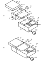
- 2A and 2B are perspective views showing an example of the structure of a charging system for a secondary battery including an auxiliary electronic device for a charger according to the first embodiment of the present invention.
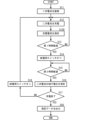
- FIG. 3 is a flowchart showing an example of charging control and OCV measurement of an auxiliary electronic device for a charger when the power supply switch according to the first embodiment is of a normally-on type.
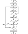
- FIG. 4 is a flowchart showing an example of charging control and OCV measurement of an auxiliary electronic device for a charger when the power supply switch according to the first embodiment is of a normally-off type.
- FIG. 1 is a circuit diagram of a charging system for a secondary battery including an auxiliary electronic device for a charger according to a first embodiment of the present invention.
- 2A and 2B are perspective views showing an example of the structure of a charging system for a secondary battery including an
- FIG. 5 is a circuit diagram of a charging system for a secondary battery including an auxiliary electronic device for a charger according to a second embodiment of the present invention.
- 6A and 6B are perspective views showing an example of the structure of a charging system for a secondary battery including an auxiliary electronic device for a charger according to a second embodiment of the present invention.
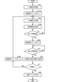
- FIG. 7 is a flowchart showing an example of charging control and OCV measurement of an auxiliary electronic device for a charger when the communication switch according to the second embodiment is of a normally-on type.
- FIG. 8 is a flowchart showing an example of charging control and OCV measurement of an auxiliary electronic device for a charger when the communication switch according to the second embodiment is of a normally-off type.
- circuit configuration of charging system 1 is a circuit diagram of a charging system for a secondary battery including an auxiliary electronic device for a charger according to a first embodiment of the present invention. As shown in FIG. 1, the charging system includes a lithium-ion battery pack 10, an auxiliary electronic device for a charger 40, and a charger 90.
- the lithium ion battery pack 10 includes a lithium ion battery cell 20, an MPU 21, a protection IC 22, an operational amplifier 23 (OP-AMP), an LDO 24, a relay circuit 25, a fuse 26, and a measurement resistor 200.
- the lithium ion battery pack 10 includes a positive terminal Pvcc+ and a negative terminal Pvcc-.
- the positive terminal Pvcc+ is connected to a relay circuit 25.
- the positive electrode of the lithium-ion battery cell 20 is connected to the relay circuit 25.
- the negative electrode of the lithium-ion battery cell 20 is connected to the negative terminal Pvcc- via a measuring resistor 200 and a fuse 26.
- the lithium ion battery cell 20 is composed of, for example, multiple individual lithium ion batteries connected in series.
- the MPU 21 is connected to the protection IC 22, the relay circuit 25, and the operational amplifier 23.
- the MPU 21 is connected to the positive terminal Pvcc+ and the negative terminal Pvcc-, which allows power to be supplied from the outside (the charger 90 via the auxiliary electronic device 40 for the charger).
- the protection IC 22 is connected to the lithium ion battery cell 20. More specifically, the protection IC 22 is connected to each of a number of nodes where a number of individual lithium ions are connected in series in sequence. The protection IC 22 is supplied with power through the LDO 24.
- the operational amplifier 23 is connected to both ends of the measurement resistor 200.
- the relay circuit 25 includes a series circuit of a switching element Q1 and a switching element Q2.
- the switching elements Q1 and Q2 are, for example, n-channel MOSFETs.
- the series circuit of the switching elements Q1 and Q2 is connected between the positive terminal Pvcc+ and the positive electrode of the lithium-ion battery cell 20.
- the source terminal of switching element Q1 and the source terminal of switching element Q2 are connected.
- the drain terminal of switching element Q1 is connected to the positive electrode of the lithium-ion battery cell 20.
- the drain terminal of switching element Q2 is connected to the positive electrode terminal Pvcc+.
- the gate terminal of switching element Q1 and the gate terminal of switching element Q2 are connected to the MPU 21.
- the MPU 21 and protection IC 22 control charging and discharging of the lithium-ion battery cell 20.
- the MPU 21 outputs control signals for charging and discharging to the relay circuit 25.
- the first control signal is a signal that connects or disconnects the drain and source terminals of the switching elements Q1 and Q2 to connect or cut off the power supply to the lithium-ion battery cell 20.
- the protection IC 22 protects the lithium-ion battery cell 20 from overcharging and over-discharging during charging and discharging based on the potential difference between multiple nodes of the lithium-ion battery cell 20.
- the operational amplifier 23 detects the voltage across the measurement resistor 200 and outputs it to the MPU 21.
- the MPU 21 controls the power supply to the lithium ion battery cell 20 based on the detected voltage across the resistor 20.
- the charger auxiliary electronic device 40 includes an MPU 41, a voltmeter 42, an ammeter 43, a communication unit 44, a power supply switch SWp, and an interface IF.
- the MPU 41 corresponds to the "control unit” of the present invention.
- the reference numeral 42 corresponds to the "voltage measuring section” of the present invention, and the ammeter 43 corresponds to the "current measuring section” of the present invention.
- the charger auxiliary electronic device 40 includes a first positive terminal 491, a second positive terminal 493, a first negative terminal 492, and a second negative terminal 494.
- the first positive terminal 491 and the first negative terminal 492 are terminals connected to the charger 90 and constitute a first terminal pair.
- the second positive terminal 493 and the second negative terminal 494 are terminals connected to the lithium ion battery pack 10 and constitute a second terminal pair.
- the power supply switch SWp is connected to the first positive terminal 491.
- the power supply switch SWp is connected to the ammeter 43.
- the ammeter 43 is connected to the second positive terminal 493. In this way, the power supply switch SWp is configured to open and close the power supply line.
- the voltmeter 42 is connected between the second positive terminal 493 and the second negative terminal 494.
- the power supply switch SWp is a semiconductor switch with a large current capacity for power, for example a power MOS-FET.
- the power supply switch SWp may be of either a normally-off type or a normally-on type.
- the charging control performed by the MPU 41 differs depending on the type of the power supply switch SWp.
- the MPU 41 is connected to a voltmeter 42, an ammeter 43, a power supply switch SWp, and a communication unit 44. Although not shown in the figure, the MPU 41 is connected to a first positive terminal 491 and a first negative terminal 492, which allows power to be supplied from the outside (charger 90).
- the MPU 41 is equipped with a timer, and performs intermittent charging of the lithium-ion battery pack 10 by controlling the opening and closing of the power supply switch SWp while keeping time with the timer.
- the voltage value measured by the voltmeter 42 and the current value measured by the ammeter 43 are also input to the MPU 41.
- the MPU 41 outputs the voltage value and current value during intermittent charging to the communication unit 44.
- the specific intermittent charging method, and the specific methods for measuring and outputting the voltage value and current value at this time will be described later.
- the communication unit 44 transmits pairs of voltage and current values from the MPU 41 to an external device (e.g., an SOC-OCV characteristic analysis device) via the interface IF.
- an external device e.g., an SOC-OCV characteristic analysis device
- the charger 90 includes a charging control unit 91 and an AC-DC converter 92.
- the charger 90 includes a positive terminal 991 and a negative terminal 992.
- the charging control unit 91 is connected to the AC-DC converter 92, the positive terminal 991, and the negative terminal 992.
- the AC-DC converter 92 is connected to a commercial AC power source.
- the AC-DC converter 92 converts AC power into DC power and outputs it to the charging control unit 91.
- the charging control unit 91 generates the voltage and current for charging using DC power from the AC-DC converter 92.
- FIG. 2A and 2B are perspective views showing an example of the structure of a charging system for a secondary battery including an auxiliary electronic device for a charger according to the first embodiment of the present invention.
- Fig. 2A shows a state in which the lithium ion battery pack, the auxiliary electronic device for a charger, and the charger are separated
- Fig. 2B shows a state in which the auxiliary electronic device for a charger is attached to the charger, and the lithium ion battery pack is attached to the auxiliary electronic device for a charger.
- the lithium-ion battery pack 10 includes a housing 100.
- the housing 100 is substantially rectangular.
- the lithium-ion battery cell 20, the MPU 21, the protection IC 22, the operational amplifier 23 (OP-AMP), the LDO 24, the relay circuit 25, the fuse 26, and the measurement resistor 200 are housed within the housing 100.
- the positive terminal Pvcc+ and the negative terminal Pvcc- are formed on one side of the housing 100.
- the charger auxiliary electronic device 40 includes a housing 400.
- the housing 400 includes a main body 401 and a protruding portion 402, each of which has a substantially rectangular parallelepiped shape.
- the main body 401 includes a recess 411.
- the MPU 41, voltmeter 42, ammeter 43, communication unit 44, and power supply switch SWp of the charger auxiliary electronic device 40 are housed in a housing 400.
- the interface IF is formed in the main body 401.
- the first positive electrode terminal 491 and the first negative electrode terminal 492 are formed on the tip surface of the protrusion 402.
- the second positive electrode terminal 493 and the second negative electrode terminal 494 are formed on the wall surface that constitutes the recess 411.
- the charger 90 includes a housing 900.
- the housing 900 has a substantially rectangular parallelepiped shape. However, the shape of the housing 900 is not limited to this.
- the housing 900 has a recess 911 formed therein.
- the charging control unit 91 and AC-DC converter 92 of the charger 90 are housed in a housing 900.
- the AC-DC converter 92 is connected to a power cable 914 that extends from the housing 900 to the outside.
- the positive electrode terminal 991 and the negative electrode terminal 992 are formed on the wall surface that constitutes the recess 911.
- the charger 90 includes a display unit 912 and multiple operation buttons 913 on the surface of the housing 900.
- the display unit 912 displays, for example, the operating status of the charger 90.
- the multiple operation buttons 913 accept operation inputs for charging.
- the protrusion 402 of the charger auxiliary electronic device 40 is attached to the recess 911 of the charger 90. This brings the first positive terminal 491 of the charger auxiliary electronic device 40 into contact with the positive terminal 991 of the charger 90 and electrically connects them. The first negative terminal 492 of the charger auxiliary electronic device 40 into contact with the negative terminal 992 of the charger 90 and electrically connects them.
- the lithium-ion battery pack 10 is also attached to the recess 411 of the charger auxiliary electronic device 40. This brings the second positive terminal 493 of the charger auxiliary electronic device 40 into contact with and electrically connects the positive terminal Pvcc+ of the lithium-ion battery pack 10. The second negative terminal 494 of the charger auxiliary electronic device 40 into contact with and electrically connects the negative terminal Pvcc- of the lithium-ion battery pack 10.
- the lithium-ion battery pack 10 is electrically connected to the charger 90 through the auxiliary charger electronic device 40, making it possible to charge it.
- FIG. 3 is a flowchart showing an example of charging control and OCV measurement of an auxiliary electronic device for a charger when the power supply switch according to the first embodiment is of a normally-on type.
- the lithium-ion battery pack 10 (secondary battery) is attached to the charger auxiliary electronic device 40 (S11: YES), and when the charger auxiliary electronic device 40 is attached to the charger 90, charging of the lithium-ion battery pack 10 (secondary battery) begins (S12).
- the MPU 41 is equipped with a timer, and when charging of the lithium-ion battery pack 10 (secondary battery) begins, it measures the charging time. The MPU 41 continues charging until the first charging time for intermittent charging has elapsed (S13: NO). At this time, the ammeter 43 measures the charging current value and outputs it to the MPU 41.
- the MPU 41 controls the power supply switch SWp to turn off (S14).
- the MPU 41 measures the charging pause time.
- the MPU 41 maintains the turn-off control of the power supply switch SWp until the charging pause time for intermittent charging has elapsed for the second time (S15: NO).
- the voltmeter 42 measures the terminal voltage value (OCV value) of the lithium-ion battery pack 10 (secondary battery). The voltmeter 42 outputs the terminal voltage value to the MPU 41.
- the MPU 41 has a memory and stores the charging current value and the terminal voltage value in pairs in the memory.
- the MPU 41 controls the power supply switch SWp to turn on (S18).
- the charging system then repeats the above-mentioned charging and measurement of the charging current value and terminal voltage value. The end of charging can be determined by detecting the full charge state of the lithium-ion battery pack 10 (secondary battery).
- the MPU 41 When charging of the lithium-ion battery pack 10 (secondary battery) is completed (S17: YES), the MPU 41 outputs a pair of the charging current value and terminal voltage value measured up to that point as measurement data to the communication unit 44 (S20). The communication unit 44 transmits the measurement data to an external device via the interface IF.
- the charger auxiliary electronic device 40 can be realized in a smaller shape than the charger 90. This makes it possible to measure the OCV while charging the lithium-ion battery pack 10 (secondary battery) without using a large-scale device.
- the MPU 41 may include a calculation unit and calculate the charged capacity value from the charging current value and store it in memory. Furthermore, the voltmeter 42 may measure the voltage value during charging, and the MPU 41 may calculate the charging power value from the voltage value during charging and the charging current value in the calculation unit and store it in memory. The MPU 41 may then output these capacity values and charging power values as measurement data.
- FIG. 4 is a flowchart showing an example of charging control and OCV measurement of an auxiliary electronic device for a charger when the power supply switch according to the first embodiment is of the normally-off type. Note that when the power supply switch SWp is of the normally-off type, only the control at the start of charging the lithium-ion battery pack 10 (secondary battery) is different from when the power supply switch SWp is of the normally-on type. Therefore, only the differences will be described below.
- the MPU 41 controls the power supply switch SWp to turn on (S111). This starts charging the lithium-ion battery pack 10 (secondary battery). Thereafter, the charger auxiliary electronic device 40 performs the same control as when the power supply switch SWp is of the normally-off type, and performs intermittent charging of the lithium-ion battery pack 10 (secondary battery) and OCV measurement.
- FIG. 5 is a circuit diagram of a charging system for a secondary battery including an auxiliary electronic device for a charger according to a second embodiment of the present invention.
- the charging system includes a lithium-ion battery pack 10A, an auxiliary electronic device for the charger 40A, and a charger 90A.
- the lithium-ion battery pack 10A differs from the lithium-ion battery pack 10 according to the first embodiment in that it includes an MPU 21A, a communication terminal Pcl+, and a communication terminal Pcl-.
- the rest of the configuration of the lithium-ion battery pack 10A is the same as that of the lithium-ion battery pack 10, and a description of similar parts will be omitted.
- the MPU 21A is connected to the communication terminals Pcl+ and Pcl-.
- the MPU 21A has the function of communicating with the outside world through the communication terminals Pcl+ and Pcl-.
- the MPU 21A stores the ID of the lithium-ion battery pack 10A and can communicate the ID to the outside world.
- the charger auxiliary electronic device 40A differs from the charger auxiliary electronic device 40 according to the first embodiment in that it does not have a power supply switch SWp, but has communication switches SWt1 and SWt2, an MPU 41A, and multiple communication terminals 495, 496, 497, and 498.
- the rest of the configuration of the charger auxiliary electronic device 40A is the same as that of the charger auxiliary electronic device 40, and a description of similar parts will be omitted.
- the ammeter 43 has a first positive terminal 491 and a second positive terminal 493.
- the communication terminals 495 and 496 constitute a charger side communication terminal pair.
- the communication terminals 497 and 498 constitute a secondary battery side communication terminal pair.
- Communication switch SWt1 is connected between communication terminal 495 and communication terminal 497.
- Communication switch SWt2 is connected between communication terminal 496 and communication terminal 498.
- communication switch SWt1 and communication switch SWt2 are arranged to open and close the communication line.
- the communication switches SWt1 and SWt2 are small current capacity semiconductor switches. By using small current capacity semiconductor switches, the communication switches SWt1 and SWt2 can be made smaller, which also leads to a smaller charger auxiliary electronic device 40A. Furthermore, by using small current capacity semiconductor switches, the amount of heat generated by the communication switches SWt1 and SWt2 can be reduced. This allows, for example, the heat dissipation structure of the charger auxiliary electronic device 40A to be simplified, making it easier to achieve miniaturization.
- the MPU 41A is connected to the communication switch SWt1 and the communication switch SWt2.
- the MPU 41A controls the turn-on and turn-off of the communication switch SWt1 and the communication switch SWt2.
- the charger 90A differs from the charger 90 according to the first embodiment in that it includes a charging control unit 91A, a communication terminal 993, and a communication terminal 994.
- the rest of the configuration of the charger 90A is the same as that of the charger 90, and a description of the similar parts will be omitted.
- the charging control unit 91A is connected to the communication terminal 993 and the communication terminal 994.
- the charging control unit 91A controls the supply of charging power based on the information of the lithium ion battery pack 10A received through the communication terminals 993 and 994. For example, the charging control unit 91A supplies charging power if the ID of the lithium ion battery pack 10A matches the ID of the charging permission, and does not supply charging power if they do not match.
- FIGS. 6A and 6B are perspective views showing an example of the structure of a charging system for a secondary battery including an auxiliary electronic device for a charger according to a second embodiment of the present invention, in which Fig. 6A shows a state in which the lithium ion battery pack, the auxiliary electronic device for a charger, and the charger are separated, and Fig. 6B shows a state in which the auxiliary electronic device for a charger is attached to the charger, and the lithium ion battery pack is attached to the auxiliary electronic device for a charger.
- the external shapes of the lithium-ion battery pack 10A, the auxiliary electronic device for the charger 40A, and the charger 90A are approximately the same as the external shapes of the lithium-ion battery pack 10, the auxiliary electronic device for the charger 40, and the charger 90, respectively, but differ in the arrangement of each terminal.
- the lithium-ion battery pack 10A has a positive terminal Pvcc+, a communication terminal Pcl+, a communication terminal Pcl-, and a negative terminal Pvcc- on one side of the housing 100.
- the charger auxiliary electronic device 40A has a first positive terminal 491, a communication terminal 495, a communication terminal 496, and a first negative terminal 492 on the tip surface of the protrusion 402.
- the charger auxiliary electronic device 40A has a second positive terminal 493, a communication terminal 497, a communication terminal 498, and a second negative terminal 494 on the wall surface that forms the recess 411.
- the charger 90A has a positive terminal 991, a communication terminal 993, a communication terminal 994, and a negative terminal 992 on the wall surface that forms the recess 911.
- the protrusion 402 of the charger auxiliary electronic device 40A is attached to the recess 911 of the charger 90A.
- the first positive terminal 491 of the charger auxiliary electronic device 40A and the positive terminal 991 of the charger 90A come into contact and are electrically connected.
- the first negative terminal 492 of the charger auxiliary electronic device 40A and the negative terminal 992 of the charger 90A come into contact and are electrically connected.
- the communication terminal 495 of the charger auxiliary electronic device 40A and the communication terminal 993 of the charger 90A come into contact and are electrically connected.
- the communication terminal 496 of the charger auxiliary electronic device 40A and the communication terminal 994 of the charger 90A come into contact and are electrically connected.
- the lithium-ion battery pack 10A is also attached to the recess 411 of the charger auxiliary electronic device 40A.
- the second positive terminal 493 of the charger auxiliary electronic device 40A and the positive terminal Pvcc+ of the lithium-ion battery pack 10A come into contact and are electrically connected.
- the second negative terminal 494 of the charger auxiliary electronic device 40A and the negative terminal Pvcc- of the lithium-ion battery pack 10A come into contact and are electrically connected.
- the communication terminal 497 of the charger auxiliary electronic device 40A and the communication terminal Pcl+ of the lithium-ion battery pack 10A come into contact and are electrically connected.
- the communication terminal 498 of the charger auxiliary electronic device 40A and the communication terminal Pcl- of the lithium-ion battery pack 10A come into contact and are electrically connected.
- the lithium ion battery pack 10A is electrically connected to the charger 90A through the charger auxiliary electronic device 40A, making it possible to charge and communicate.
- FIG. 7 is a flowchart showing an example of charging control and OCV measurement of an auxiliary electronic device for a charger when the communication switch according to the second embodiment is of a normally-on type.
- the MPU 41A controls the communication switches SWt1 and SWt2 to turn off (S14A).
- the charger 90A determines that the lithium-ion battery pack 10A is not connected and stops supplying charging power. This allows for a period of charging suspension for measuring the OCV.
- the MPU 41A controls the communication switches SWt1 and SWt2 to turn on (S18A). This restarts communication between the charger 90A and the lithium-ion battery pack 10A.
- the charger 90A determines that the lithium-ion battery pack 10A is connected and supplies charging power.
- FIG. 8 is a flowchart showing an example of charging control and OCV measurement of an auxiliary electronic device for a charger when the communication switch according to the second embodiment is of the normally-off type.
- the lithium-ion battery pack 10A (secondary battery) is attached to the charger auxiliary electronic device 40A (S11: YES), and when the charger auxiliary electronic device 40A is attached to the charger 90A, the MPU 41A controls the communication switches SWt1 and SWt2 to turn on (S111A).
- S11 YES
- the charger auxiliary electronic device 40A controls the communication switches SWt1 and SWt2 to turn on (S111A).
- the charger auxiliary electronic device 40A performs the same control as when the communication switches SWt1 and SWt2 are of the normally-off type, and performs intermittent charging of the lithium-ion battery pack 10A (secondary battery) and OCV measurement.
- the auxiliary electronic device for charger 40A can receive these values.
- the auxiliary electronic device for charger 40A can omit the voltmeter 42 and ammeter 43.
- the interface IF is described as a terminal for wired communication, but it may also be a wireless communication terminal.
- a voltage measuring unit A current measuring unit; A normally-on switch; A control unit having a timer; an interface for outputting the voltage value measured by the voltage measurement unit and the current value measured by the current measurement unit; A secondary battery side terminal to be connected to the secondary battery; a charger side terminal for connecting to a charger for charging the secondary battery;
- An auxiliary electronic device for a charger comprising: the switch is provided to open and close a power supply line or a communication line between the secondary battery and the charger, The control unit is When the secondary battery and the charger are connected through the auxiliary electronic device for the charger, the switch is turned off after a first time period.
- the voltage measurement unit is measuring a terminal voltage of the secondary battery after a second time has elapsed since the switch was turned off and outputting the measured voltage to the control unit;
- the control unit is An auxiliary electronic device for the charger outputs, via the interface, the measured voltage value and at least one of the current value measured during the first time period or the capacity value charged to the secondary battery during the first time period.
- a voltage measuring unit A current measuring unit; A normally-off switch; A control unit having a timer; an interface for outputting the voltage value measured by the voltage measurement unit and the current value measured by the current measurement unit;
- a secondary battery side terminal to be connected to the secondary battery;
- a charger side terminal for connecting to a charger for charging the secondary battery;
- An auxiliary electronic device for a charger comprising: the switch is provided to open and close a power supply line or a communication line between the secondary battery and the charger, The control unit is When the secondary battery and the charger are connected through the auxiliary electronic device for the charger, the switch is turned on.
- the voltage measurement unit is measuring a terminal voltage of the secondary battery after a second time has elapsed since the switch was turned off and outputting the measured voltage to the control unit;
- the control unit is An auxiliary electronic device for the charger outputs, via the interface, the measured voltage value and at least one of the current value measured during the first time period or the capacity value charged to the secondary battery during the first time period.
- the control unit is a calculation unit that calculates a power value from the current value and the voltage value during the first time period,
- the auxiliary electronic device for a charger according to ⁇ 1> or ⁇ 2> which outputs the power value through the interface.
- the control unit is a memory for temporarily storing the voltage value, the current value, and the power value;
- ⁇ 5> An auxiliary electronic device for a charger according to any one of ⁇ 1> to ⁇ 4>, wherein the interface is an interface for wireless communication.
- ⁇ 6> An auxiliary electronic device for a charger according to any one of ⁇ 1> to ⁇ 5>, wherein the switch is provided on the power supply line and is a semiconductor switch with a large current capacity for power.
- auxiliary electronic device for a charger according to any one of ⁇ 1> to ⁇ 5>, wherein the switch is provided on the communication line and is a semiconductor switch with a small current capacity for communication.
Landscapes
- Charge And Discharge Circuits For Batteries Or The Like (AREA)
Abstract
Description
本発明の第1の実施形態に係る充電器用補助電子装置および充電システムについて、図を参照して説明する。
図1は、本発明の第1の実施形態に係る充電器用補助電子装置を含む二次電池の充電システムの回路図である。図1に示すように、充電システムは、リチウムイオン電池パック10、充電器用補助電子装置40、および、充電器90を備える。
リチウムイオン電池パック10は、リチウムイオン電池セル20、MPU21、保護IC22、オペアンプ23(OP-AMP)、LDO24、リレー回路25、ヒューズ26、および、計測用抵抗200を備える。リチウムイオン電池パック10は、正極端子Pvcc+、および、負極端子Pvcc-を備える。
充電器用補助電子装置40は、MPU41、電圧計42、電流計43、通信部44、給電用スイッチSWp、および、インターフェースIFを備える。MPU41が、本発明の「制御部」に対応し、電圧計42が本発明の「電圧測定部」に対応し、電流計43が本発明の「電流測定部」に対応する。
充電器90は、充電制御部91、および、AC-DCコンバータ92を備える。充電器90は、正極端子991および負極端子992を備える。充電制御部91は、AC-DCコンバータ92、正極端子991、および、負極端子992に接続される。
図2(A)および図2(B)は、本発明の第1の実施形態に係る充電器用補助電子装置を含む二次電池の充電システムの構造の一例を示す斜視図である。図2(A)は、リチウムイオン電池パック、充電器用補助電子装置、および、充電器が分離した状態を示し、図2(B)は、充電器に充電器用補助電子装置が装着され、充電器用補助電子装置にリチウムイオン電池パックが装着された状態を示す。
図3は、第1の実施形態に係る給電用スイッチがノーマリーオン型の場合における充電器用補助電子装置の充電制御およびOCV測定の一例を示すフローチャートである。
本発明の第2の実施形態に係る充電器用補助電子装置および充電システムについて、図を参照して説明する。第2の実施形態に係る充電システムは、第1の実施形態に係る充電システムに対して、間欠充電のための構成および制御が異なる。
図5は、本発明の第2の実施形態に係る充電器用補助電子装置を含む二次電池の充電システムの回路図である。
との間に接続される。通信端子495と通信端子496は、充電器側通信端子対を構成する。通信端子497と通信端子498は、二次電池側通信端子対を構成する。
図6(A)および図6(B)は、本発明の第2の実施形態に係る充電器用補助電子装置を含む二次電池の充電システムの構造の一例を示す斜視図である。図6(A)は、リチウムイオン電池パック、充電器用補助電子装置、および、充電器が分離した状態を示し、図6(B)は、充電器に充電器用補助電子装置が装着され、充電器用補助電子装置にリチウムイオン電池パックが装着された状態を示す。
図7は、第2の実施形態に係る通信用スイッチがノーマリーオン型の場合における充電器用補助電子装置の充電制御およびOCV測定の一例を示すフローチャートである。
電流測定部と、
ノーマリーオン型のスイッチと、
タイマーを備えた制御部と、
前記電圧測定部にて測定した電圧値および前記電流測定部にて測定した電流値を出力するインターフェースと、
二次電池に接続する二次電池側端子と、
前記二次電池を充電するための充電器に接続する充電器側端子と、
を備えた充電器用補助電子装置であって、
前記スイッチは前記二次電池と前記充電器との間の電源ラインまたは通信ラインを開閉するように設けられ、
前記制御部は、
前記充電器用補助電子装置を通じて前記二次電池と前記充電器が接続されると、第1時間の後に前記スイッチをターンオフ制御し、
前記電圧測定部は、
前記スイッチのターンオフから第2時間が経過した後の前記二次電池の端子電圧を測定して前記制御部に出力し、
前記制御部は、
前記測定した電圧値と、前記第1時間の間に測定された前記電流値または前記第1時間の間に前記二次電池に充電された容量値の少なくとも一方とを、前記インターフェースを通じて出力する、充電器用補助電子装置。
電流測定部と、
ノーマリーオフ型のスイッチと、
タイマーを備えた制御部と、
前記電圧測定部にて測定した電圧値および前記電流測定部にて測定した電流値を出力するインターフェースと、
二次電池に接続する二次電池側端子と、
前記二次電池を充電するための充電器に接続する充電器側端子と、
を備えた充電器用補助電子装置であって、
前記スイッチは前記二次電池と前記充電器との間の電源ラインまたは通信ラインを開閉するように設けられ、
前記制御部は、
前記充電器用補助電子装置を通じて前記二次電池と前記充電器が接続されると、前記スイッチをターンオン制御し、
前記スイッチのターンオンから第1時間の後に前記スイッチをターンオフ制御し、
前記電圧測定部は、
前記スイッチのターンオフから第2時間が経過した後の前記二次電池の端子電圧を測定して前記制御部に出力し、
前記制御部は、
前記測定した電圧値と、前記第1時間の間に測定された前記電流値または前記第1時間の間に前記二次電池に充電された容量値の少なくとも一方とを、前記インターフェースを通じて出力する、充電器用補助電子装置。
前記第1時間の前記電流値と前記電圧値から電力値を算出する演算部を有し、
前記電力値を前記インターフェースを通じて出力する、<1>または<2>の充電器用補助電子装置。
前記電圧値、前記電流値、および、前記電力値を一時記憶するメモリを備え、
前記メモリで一時記憶した前記電圧値、前記電流値、および、前記電力値を一括して前記インターフェースを通じて出力する、<3>の充電器用補助電子装置。
20:リチウムイオン電池セル
21、21A:MPU
22:保護IC
23:オペアンプ
24:LDO
25:リレー回路
26:ヒューズ
40、40A:充電器用補助電子装置
41、41A:MPU
42:電圧計
43:電流計
44:通信部
90、90A:充電器
91、91A:充電制御部
92:AC-DCコンバータ
100:筐体
200:計測用抵抗
400:筐体
401:本体部
402:突出部
411:凹部
491:第1正極端子
492:第1負極端子
493:第2正極端子
494:第2負極端子
495、496、497、498:通信端子
900:筐体
911:凹部
912:表示部
913:操作ボタン
914:電源ケーブル
991:正極端子
992:負極端子
993、994:通信端子
IF:インターフェース
Pcl+、Pcl-:通信端子
Pvcc+:正極端子
Pvcc-:負極端子
Q1、Q2:スイッチング素子
SWp:給電用スイッチ
SWt1、SWt2:通信用スイッチ
Claims (7)
- 電圧測定部と、
電流測定部と、
ノーマリーオン型のスイッチと、
タイマーを備えた制御部と、
前記電圧測定部にて測定した電圧値および前記電流測定部にて測定した電流値を出力するインターフェースと、
二次電池に接続する二次電池側端子と、
前記二次電池を充電するための充電器に接続する充電器側端子と、
を備えた充電器用補助電子装置であって、
前記スイッチは前記二次電池と前記充電器との間の電源ラインまたは通信ラインを開閉するように設けられ、
前記制御部は、
前記充電器用補助電子装置を通じて前記二次電池と前記充電器が接続されると、第1時間の後に前記スイッチをターンオフ制御し、
前記電圧測定部は、
前記スイッチのターンオフから第2時間が経過した後の前記二次電池の端子電圧を測定して前記制御部に出力し、
前記制御部は、
前記測定した電圧値と、前記第1時間の間に測定された前記電流値または前記第1時間の間に前記二次電池に充電された容量値の少なくとも一方とを、前記インターフェースを通じて出力する、
充電器用補助電子装置。 - 電圧測定部と、
電流測定部と、
ノーマリーオフ型のスイッチと、
タイマーを備えた制御部と、
前記電圧測定部にて測定した電圧値および前記電流測定部にて測定した電流値を出力するインターフェースと、
二次電池に接続する二次電池側端子と、
前記二次電池を充電するための充電器に接続する充電器側端子と、
を備えた充電器用補助電子装置であって、
前記スイッチは前記二次電池と前記充電器との間の電源ラインまたは通信ラインを開閉するように設けられ、
前記制御部は、
前記充電器用補助電子装置を通じて前記二次電池と前記充電器が接続されると、前記スイッチをターンオン制御し、
前記スイッチのターンオンから第1時間の後に前記スイッチをターンオフ制御し、
前記電圧測定部は、
前記スイッチのターンオフから第2時間が経過した後の前記二次電池の端子電圧を測定して前記制御部に出力し、
前記制御部は、
前記測定した電圧値と、前記第1時間の間に測定された前記電流値または前記第1時間の間に前記二次電池に充電された容量値の少なくとも一方とを、前記インターフェースを通じて出力する、
充電器用補助電子装置。 - 前記制御部は、
前記第1時間の前記電流値と前記電圧値から電力値を算出する演算部を有し、
前記電力値を前記インターフェースを通じて出力する、
請求項1または請求項2に記載の充電器用補助電子装置。 - 前記制御部は、
前記電圧値、前記電流値、および、前記電力値を一時記憶するメモリを備え、
前記メモリで一時記憶した前記電圧値、前記電流値、および、前記電力値を一括して前記インターフェースを通じて出力する、
請求項3に記載の充電器用補助電子装置。 - 前記インターフェースは、無線通信用のインターフェースである、
請求項1乃至請求項4のいずれかに記載の充電器用補助電子装置。 - 前記スイッチは、前記電源ラインに設けられており、電力用の大電流容量の半導体スイッチである、
請求項1乃至請求項5のいずれかに記載の充電器用補助電子装置。 - 前記スイッチは、前記通信ラインに設けられており、通信用の小電流容量の半導体スイッチである、
請求項1乃至請求項5のいずれかに記載の充電器用補助電子装置。
Priority Applications (1)
| Application Number | Priority Date | Filing Date | Title |
|---|---|---|---|
| JP2025519327A JPWO2024232154A1 (ja) | 2023-05-10 | 2024-03-11 |
Applications Claiming Priority (2)
| Application Number | Priority Date | Filing Date | Title |
|---|---|---|---|
| JP2023-077627 | 2023-05-10 | ||
| JP2023077627 | 2023-05-10 |
Publications (1)
| Publication Number | Publication Date |
|---|---|
| WO2024232154A1 true WO2024232154A1 (ja) | 2024-11-14 |
Family
ID=93431489
Family Applications (1)
| Application Number | Title | Priority Date | Filing Date |
|---|---|---|---|
| PCT/JP2024/009224 Ceased WO2024232154A1 (ja) | 2023-05-10 | 2024-03-11 | 充電器用補助電子装置 |
Country Status (2)
| Country | Link |
|---|---|
| JP (1) | JPWO2024232154A1 (ja) |
| WO (1) | WO2024232154A1 (ja) |
Citations (6)
| Publication number | Priority date | Publication date | Assignee | Title |
|---|---|---|---|---|
| JP2008058260A (ja) * | 2006-09-04 | 2008-03-13 | Fujitsu Ltd | 電池制御装置、電池制御方法、電源制御装置、及び電子機器 |
| JP2010238585A (ja) * | 2009-03-31 | 2010-10-21 | Nec Corp | 移動体通信機器、移動体通信機器の制御方法、及びプログラム |
| JP2012202851A (ja) * | 2011-03-25 | 2012-10-22 | Nec Energy Devices Ltd | 劣化測定装置、二次電池パック、劣化測定方法、およびプログラム |
| US20160301226A1 (en) * | 2015-04-08 | 2016-10-13 | Intel Corporation | Systems, methods and devices for adaptable battery charging |
| WO2019181764A1 (ja) * | 2018-03-20 | 2019-09-26 | 株式会社村田製作所 | 電池制御装置、電池制御方法、無停電電源装置、電力システム及び電動車両 |
| WO2022014280A1 (ja) * | 2020-07-17 | 2022-01-20 | パナソニックIpマネジメント株式会社 | 情報処理方法及び充電制御装置 |
-
2024
- 2024-03-11 WO PCT/JP2024/009224 patent/WO2024232154A1/ja not_active Ceased
- 2024-03-11 JP JP2025519327A patent/JPWO2024232154A1/ja active Pending
Patent Citations (6)
| Publication number | Priority date | Publication date | Assignee | Title |
|---|---|---|---|---|
| JP2008058260A (ja) * | 2006-09-04 | 2008-03-13 | Fujitsu Ltd | 電池制御装置、電池制御方法、電源制御装置、及び電子機器 |
| JP2010238585A (ja) * | 2009-03-31 | 2010-10-21 | Nec Corp | 移動体通信機器、移動体通信機器の制御方法、及びプログラム |
| JP2012202851A (ja) * | 2011-03-25 | 2012-10-22 | Nec Energy Devices Ltd | 劣化測定装置、二次電池パック、劣化測定方法、およびプログラム |
| US20160301226A1 (en) * | 2015-04-08 | 2016-10-13 | Intel Corporation | Systems, methods and devices for adaptable battery charging |
| WO2019181764A1 (ja) * | 2018-03-20 | 2019-09-26 | 株式会社村田製作所 | 電池制御装置、電池制御方法、無停電電源装置、電力システム及び電動車両 |
| WO2022014280A1 (ja) * | 2020-07-17 | 2022-01-20 | パナソニックIpマネジメント株式会社 | 情報処理方法及び充電制御装置 |
Also Published As
| Publication number | Publication date |
|---|---|
| JPWO2024232154A1 (ja) | 2024-11-14 |
Similar Documents
| Publication | Publication Date | Title |
|---|---|---|
| CN101051760B (zh) | 电池组件以及使用该电池组件的电子设备 | |
| CN101192757B (zh) | 充电系统、充电装置以及电池组件 | |
| JP4627588B2 (ja) | 電池パックとその検査装置 | |
| EP2685270B1 (en) | Measurement system | |
| EP2221937B1 (en) | Built-in charge circuit for secondary battery and secondary battery with the built-in charge circuit | |
| JP3713770B2 (ja) | 二次電池パック | |
| JP4237804B2 (ja) | 組電池の保護装置及び電池パック装置 | |
| EP1921727A2 (en) | Hybrid battery and charging method thereof | |
| US20070103113A1 (en) | Methods of charging battery packs for cordless power tool systems | |
| CN102005733A (zh) | 电池组及其功能停止方法 | |
| EP1796243B1 (en) | Methods of charging battery packs for cordless power tool systems | |
| TWI404296B (zh) | Multi-series multi-parallel battery pack | |
| JP2009033843A (ja) | 充電装置および充電方法 | |
| EP1994624A2 (en) | Power supply for battery powered devices | |
| US20110025272A1 (en) | Charging method, charging device, and battery pack | |
| US20050112416A1 (en) | Battery assembly and battery pack | |
| JPH06325795A (ja) | 2次電池の充電方法および装置並びに2次電池装置 | |
| JP2014045551A (ja) | パック電池及びパック電池の放電制御方法 | |
| KR101569216B1 (ko) | 배터리 팩 | |
| JP2013005561A (ja) | 二次電池の放電方法及びパック電池 | |
| JPH08265984A (ja) | 電源装置 | |
| KR101628606B1 (ko) | 과방전 배터리의 충전제어회로 및 방법 | |
| JPH09159738A (ja) | 二次電池の充放電試験装置 | |
| JP2003023736A (ja) | 組電池の充電装置 | |
| JP2022047802A (ja) | 電子機器、電池パック、制御方法およびプログラム |
Legal Events
| Date | Code | Title | Description |
|---|---|---|---|
| 121 | Ep: the epo has been informed by wipo that ep was designated in this application |
Ref document number: 24803269 Country of ref document: EP Kind code of ref document: A1 |
|
| ENP | Entry into the national phase |
Ref document number: 2025519327 Country of ref document: JP Kind code of ref document: A |
|
| WWE | Wipo information: entry into national phase |
Ref document number: 2025519327 Country of ref document: JP |
|
| WWE | Wipo information: entry into national phase |
Ref document number: 202517103426 Country of ref document: IN |
|
| WWP | Wipo information: published in national office |
Ref document number: 202517103426 Country of ref document: IN |
|
| NENP | Non-entry into the national phase |
Ref country code: DE |