WO2024232147A1 - 非接触入力装置、及び、入力支援アプリケーション - Google Patents
非接触入力装置、及び、入力支援アプリケーション Download PDFInfo
- Publication number
- WO2024232147A1 WO2024232147A1 PCT/JP2024/007967 JP2024007967W WO2024232147A1 WO 2024232147 A1 WO2024232147 A1 WO 2024232147A1 JP 2024007967 W JP2024007967 W JP 2024007967W WO 2024232147 A1 WO2024232147 A1 WO 2024232147A1
- Authority
- WO
- WIPO (PCT)
- Prior art keywords
- input
- assistance application
- pointer
- display
- input assistance
- Prior art date
- Legal status (The legal status is an assumption and is not a legal conclusion. Google has not performed a legal analysis and makes no representation as to the accuracy of the status listed.)
- Ceased
Links
Images













Classifications
-
- G—PHYSICS
- G06—COMPUTING OR CALCULATING; COUNTING
- G06F—ELECTRIC DIGITAL DATA PROCESSING
- G06F3/00—Input arrangements for transferring data to be processed into a form capable of being handled by the computer; Output arrangements for transferring data from processing unit to output unit, e.g. interface arrangements
- G06F3/01—Input arrangements or combined input and output arrangements for interaction between user and computer
- G06F3/03—Arrangements for converting the position or the displacement of a member into a coded form
- G06F3/041—Digitisers, e.g. for touch screens or touch pads, characterised by the transducing means
- G06F3/0416—Control or interface arrangements specially adapted for digitisers
- G06F3/04166—Details of scanning methods, e.g. sampling time, grouping of sub areas or time sharing with display driving
-
- G—PHYSICS
- G06—COMPUTING OR CALCULATING; COUNTING
- G06F—ELECTRIC DIGITAL DATA PROCESSING
- G06F3/00—Input arrangements for transferring data to be processed into a form capable of being handled by the computer; Output arrangements for transferring data from processing unit to output unit, e.g. interface arrangements
- G06F3/01—Input arrangements or combined input and output arrangements for interaction between user and computer
- G06F3/03—Arrangements for converting the position or the displacement of a member into a coded form
- G06F3/041—Digitisers, e.g. for touch screens or touch pads, characterised by the transducing means
-
- G—PHYSICS
- G06—COMPUTING OR CALCULATING; COUNTING
- G06F—ELECTRIC DIGITAL DATA PROCESSING
- G06F3/00—Input arrangements for transferring data to be processed into a form capable of being handled by the computer; Output arrangements for transferring data from processing unit to output unit, e.g. interface arrangements
- G06F3/01—Input arrangements or combined input and output arrangements for interaction between user and computer
- G06F3/048—Interaction techniques based on graphical user interfaces [GUI]
- G06F3/0481—Interaction techniques based on graphical user interfaces [GUI] based on specific properties of the displayed interaction object or a metaphor-based environment, e.g. interaction with desktop elements like windows or icons, or assisted by a cursor's changing behaviour or appearance
- G06F3/04812—Interaction techniques based on cursor appearance or behaviour, e.g. being affected by the presence of displayed objects
-
- G—PHYSICS
- G06—COMPUTING OR CALCULATING; COUNTING
- G06F—ELECTRIC DIGITAL DATA PROCESSING
- G06F3/00—Input arrangements for transferring data to be processed into a form capable of being handled by the computer; Output arrangements for transferring data from processing unit to output unit, e.g. interface arrangements
- G06F3/01—Input arrangements or combined input and output arrangements for interaction between user and computer
- G06F3/048—Interaction techniques based on graphical user interfaces [GUI]
- G06F3/0487—Interaction techniques based on graphical user interfaces [GUI] using specific features provided by the input device, e.g. functions controlled by the rotation of a mouse with dual sensing arrangements, or of the nature of the input device, e.g. tap gestures based on pressure sensed by a digitiser
- G06F3/0488—Interaction techniques based on graphical user interfaces [GUI] using specific features provided by the input device, e.g. functions controlled by the rotation of a mouse with dual sensing arrangements, or of the nature of the input device, e.g. tap gestures based on pressure sensed by a digitiser using a touch-screen or digitiser, e.g. input of commands through traced gestures
-
- G—PHYSICS
- G06—COMPUTING OR CALCULATING; COUNTING
- G06F—ELECTRIC DIGITAL DATA PROCESSING
- G06F3/00—Input arrangements for transferring data to be processed into a form capable of being handled by the computer; Output arrangements for transferring data from processing unit to output unit, e.g. interface arrangements
- G06F3/01—Input arrangements or combined input and output arrangements for interaction between user and computer
- G06F3/048—Interaction techniques based on graphical user interfaces [GUI]
- G06F3/0487—Interaction techniques based on graphical user interfaces [GUI] using specific features provided by the input device, e.g. functions controlled by the rotation of a mouse with dual sensing arrangements, or of the nature of the input device, e.g. tap gestures based on pressure sensed by a digitiser
- G06F3/0488—Interaction techniques based on graphical user interfaces [GUI] using specific features provided by the input device, e.g. functions controlled by the rotation of a mouse with dual sensing arrangements, or of the nature of the input device, e.g. tap gestures based on pressure sensed by a digitiser using a touch-screen or digitiser, e.g. input of commands through traced gestures
- G06F3/04886—Interaction techniques based on graphical user interfaces [GUI] using specific features provided by the input device, e.g. functions controlled by the rotation of a mouse with dual sensing arrangements, or of the nature of the input device, e.g. tap gestures based on pressure sensed by a digitiser using a touch-screen or digitiser, e.g. input of commands through traced gestures by partitioning the display area of the touch-screen or the surface of the digitising tablet into independently controllable areas, e.g. virtual keyboards or menus
-
- G—PHYSICS
- G06—COMPUTING OR CALCULATING; COUNTING
- G06F—ELECTRIC DIGITAL DATA PROCESSING
- G06F2203/00—Indexing scheme relating to G06F3/00 - G06F3/048
- G06F2203/041—Indexing scheme relating to G06F3/041 - G06F3/045
- G06F2203/04101—2.5D-digitiser, i.e. digitiser detecting the X/Y position of the input means, finger or stylus, also when it does not touch, but is proximate to the digitiser's interaction surface and also measures the distance of the input means within a short range in the Z direction, possibly with a separate measurement setup
-
- G—PHYSICS
- G06—COMPUTING OR CALCULATING; COUNTING
- G06F—ELECTRIC DIGITAL DATA PROCESSING
- G06F2203/00—Indexing scheme relating to G06F3/00 - G06F3/048
- G06F2203/048—Indexing scheme relating to G06F3/048
- G06F2203/04803—Split screen, i.e. subdividing the display area or the window area into separate subareas
-
- G—PHYSICS
- G06—COMPUTING OR CALCULATING; COUNTING
- G06F—ELECTRIC DIGITAL DATA PROCESSING
- G06F3/00—Input arrangements for transferring data to be processed into a form capable of being handled by the computer; Output arrangements for transferring data from processing unit to output unit, e.g. interface arrangements
- G06F3/01—Input arrangements or combined input and output arrangements for interaction between user and computer
- G06F3/03—Arrangements for converting the position or the displacement of a member into a coded form
- G06F3/041—Digitisers, e.g. for touch screens or touch pads, characterised by the transducing means
- G06F3/044—Digitisers, e.g. for touch screens or touch pads, characterised by the transducing means by capacitive means
- G06F3/0443—Digitisers, e.g. for touch screens or touch pads, characterised by the transducing means by capacitive means using a single layer of sensing electrodes
Definitions
- This disclosure relates to a non-contact input device and an input assistance application.
- an input terminal device that inputs user operations via a position input object, and that includes a position detection unit that detects the position of the position input object operated by the user in a non-contact manner, a display unit that displays a pointer based on the position detected by the position detection unit, and an operation processing control unit that executes a corresponding operation process based on the position detected by the position detection unit.
- the operation processing control unit has a plurality of operation modes related to the execution of the operation process, one of which includes a state in which no operation process is executed other than the movement of the pointer according to the position of the position input object, and the operation processing control unit switches between the plurality of operation modes when the user performs a specific operation via the position input object (see, for example, Patent Document 1). It is also known that the size of the pointer is changed based on the three-dimensional spatial position of the hand approaching the operation screen, depending on which position on the operation screen the hand is heading toward and the distance between the hand and the operation screen (see, for example, Patent Document 2).
- conventional input terminal devices use a dedicated application program capable of detecting three-dimensional positions in order to detect the three-dimensional position of a position input object (object) without contact. For this reason, conventional input terminal devices cannot be realized with devices equipped with application programs that can only handle two-dimensional positions.
- the objective is to provide a non-contact input device and input support application that enable non-contact input with three-dimensional movements on a device equipped with an application program that can only handle two-dimensional positions.
- the non-contact input device of the embodiment of the present disclosure includes an operation surface, a detection unit that measures the two-dimensional position of an object that is operated on the operation surface without contact and the distance from the operation surface to the object, a display arranged on the rear side of the operation surface, and a control device having an OS that uses a planar GUI and an input assistance application, the input assistance application outputs a command to the OS to display a second pointer that is different from a first pointer that the OS displays on the display in an overlay on the display according to the two-dimensional position and the distance, and outputs the two-dimensional position and a click event to the OS based on the two-dimensional position and the distance.
- FIG. 1 illustrates an example of a configuration of a non-contact input device according to an embodiment.
- 1 is a diagram illustrating an example of a configuration of an electrostatic sensor, a control device, and the like of a non-contact input device according to an embodiment
- 11A and 11B are diagrams illustrating an example of four regions according to the distance in the Z direction from the operation surface of the non-contact input device according to the embodiment.
- 2 is a diagram illustrating an OS, an input assistance application, and a predetermined application program of a control unit of the non-contact input device according to the embodiment.
- FIG. 10A and 10B are diagrams illustrating an index of the positional accuracy of an object in the non-contact input device according to the embodiment.
- FIG. 4 is a diagram illustrating an example of a display on a display of the non-contact input device according to the embodiment.
- FIG. 4 is a diagram illustrating an example of a display on a display of the non-contact input device according to the embodiment.
- FIG. 4 is a diagram illustrating an example of a display on a display of the non-contact input device according to the embodiment.
- FIG. 4 is a diagram illustrating an example of a display on a display of the non-contact input device according to the embodiment.
- FIG. 4 is a diagram illustrating an example of a display on a display of the non-contact input device according to the embodiment.
- FIG. 4 is a diagram illustrating an example of a display on a display of the non-contact input device according to the embodiment.
- FIG. 4 is a diagram illustrating an example of a display on a display of the non-contact input device according to the embodiment.
- FIG. 4 is a diagram illustrating an example of a display on a display of the non-contact input device according to the embodiment.
- FIG. 11 is a diagram illustrating an example of a process executed by an input assistance application of the non-contact input device according to the embodiment.
- FIG. 11 is a diagram illustrating an example of a process executed by an input assistance application of the non-contact input device according to the embodiment.
- FIG. 11 is a diagram illustrating an example of a process executed by an input assistance application of the non-contact input device according to the embodiment.
- FIG. 11A and 11B are diagrams illustrating an example of a modified example of a process executed by an input assistance application of the non-contact input device according to the embodiment.
- FIG. 11 is a diagram illustrating an example of a process executed by an input assistance application of the non-contact input device according to the embodiment.
- 11 is a diagram illustrating an example of a process executed by an input assistance application of the non-contact input device according to the embodiment.
- FIG. 11 is a diagram illustrating an example of a process executed by an input assistance application of the non-contact input device according to the embodiment.
- FIG. 11 is a diagram illustrating an example of a process executed by an input assistance application of the non-contact input device according to the embodiment.
- FIG. 11 is a diagram illustrating an example of a process executed by an input assistance application of the non-contact input device according to the embodiment.
- FIG. 11 is a diagram illustrating an example of a process executed by an input assistance application of the non-contact input device according to the embodiment.
- FIG. 11 is a diagram illustrating an example of a process executed by an input assistance application of the non-contact input device according to the embodiment.
- FIG. 11 is a diagram illustrating an example of a process executed by an input assistance application of the non-contact input device according to the embodiment.
- FIG. 11 is a diagram illustrating an example of a process executed by an input assistance application of the non-contact input device according to the embodiment.
- FIG. 11 is a diagram illustrating an example of a process executed by an input assistance application of the non-contact input device according to the embodiment.
- FIG. 11 is a diagram illustrating an example of a process executed by an input assistance application of the non-contact input device according to the embodiment.
- FIG. 11 is a diagram illustrating an example of a process executed by an input assistance application of the non-contact input device according to the embodiment.
- FIG. 11 is a diagram illustrating an example of a process executed by an input assistance application of the non-contact input device according to the embodiment.
- FIG. 13 illustrates an example of a setting screen.
- FIG. 2 is a diagram illustrating an example of a folder structure. 13 is a flowchart illustrating an example of a setting process.
- Fig. 1 is a diagram showing an example of the configuration of a non-contact input device 100 according to an embodiment of the present invention.
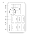
- Fig. 1 shows a state in which a display 110 displays an input image.
- FIG. 2 is a diagram showing an example of the configuration of the electrostatic sensor 120 and the control device 130 of the non-contact input device 100.
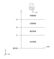
- FIG. 3 is a diagram showing four regions according to the distance in the Z direction from the operation surface 105A of the non-contact input device 100.
- the following description defines the XYZ coordinate system.
- the X axis is the first axis
- the Y axis is the second axis
- the Z axis is the third axis.
- the direction parallel to the X axis (X direction), the direction parallel to the Y axis (Y direction), and the direction parallel to the Z axis (Z direction) are mutually perpendicular.
- the -Z direction is the direction approaching the electrostatic sensor 120
- the +Z direction is the direction away from the electrostatic sensor 120.
- a planar view refers to a view from the XY plane.
- the length, width, thickness, etc. of each part may be exaggerated to make the configuration easier to understand.
- the non-contact input device 100 may be, for example, a tablet-type input device that is placed in a store or facility and used by an unspecified number of users, or the input section of an ATM (Automatic Teller Machine). It may also be an input section of a cooking appliance that needs to be kept clean.
- a tablet-type input device that is placed in a store or facility and used by an unspecified number of users, or the input section of an ATM (Automatic Teller Machine). It may also be an input section of a cooking appliance that needs to be kept clean.
- ATM Automatic Teller Machine
- the non-contact input device 100 includes a housing 101, a top panel 105, a display 110, an electrostatic sensor 120, an input sensor circuit 125A, an image display circuit 125B, and a control device 130.
- the input sensor circuit 125A calculates XYZ coordinates from the measurement results of the electrostatic sensor 120.
- the control device 130 (see FIG. 2) is omitted in FIG. 1, the control device 130 is provided, as an example, below the display 110 and the electrostatic sensor 120 inside the housing 101.
- the non-contact input device 100 includes the electrostatic sensor 120 and the control device 130 shown in FIG. 2.
- the housing 101 is a case made of resin, metal, or the like, that houses the display 110, the electrostatic sensor 120, and the control device 130.
- the display 110 is disposed below the transparent electrostatic sensor 120, and is visible through an operation surface 105A, which is the upper surface of a transparent top panel 105 provided in an opening at the top of the housing 101.
- the electrostatic sensor 120 may be retrofitted to an existing display 110.
- the display and the control device 130 may be integrated as in a tablet computer.
- the display and the control device 130 may be separate as in a desktop computer.
- the non-contact input device 100 can be operated in both a state where a pointer such as a user's hand is not in contact with the operation surface 105A and a state where a pointer such as a user's hand is in contact with the operation surface 105A.
- the non-contact input device 100 will be described together with the modes in which an input assistance application is executed.
- the input assistance application has four modes: a decision mode, a selection mode, a proximity mode, and a standby mode.
- the non-contact input device 100 is an input device that is operated by the user performing a pointing operation.
- a pointing operation is an operation performed by holding a finger substantially perpendicular to the operation surface 105A.
- the number of fingers used in the pointing operation may be multiple, but it is preferable to use one finger.
- the following describes a case where the user performs a pointing operation with the fingertip FT as the indicator.
- performing an operation (proximity operation, selection operation, decision operation, or contact operation) with the fingertip FT will simply be expressed as an operation (proximity operation, selection operation, decision operation, or contact operation) with the fingertip FT.
- the non-contact input device 100 uses the four areas shown in FIG. 3 to distinguish between the four operation methods.
- the four areas are, in order from the operation surface 105A side, a decision area, a selection area, a proximity area, and a standby area.
- the decision area is a first area whose Z-direction distance from the operation surface 105A is shorter than Z1 (e.g., 2 cm), and is an area in which the input assistance application sets the mode of the input assistance application to the decision mode.
- Z1 is an example of a first threshold value.
- the decision area also includes a Z-direction distance of 0 cm (contact) from the operation surface 105A. Note that the relationship between the Z-direction distance and the capacitance is affected by individual differences and the installation environment.
- the capacitance is inversely proportional to the Z-direction distance. Therefore, if it is sufficient to measure the relative distance to the same operator, the capacitance can be considered as the distance. Note that the decision area and the decision operation will be described in detail later.
- the input assistance application uses a value (Z value) proportional to the capacitance between the fingertip FT and the electrostatic sensor 120 instead of the distance in the Z direction.
- the input sensor circuit 125A calculates the position (XY coordinates) of the fingertip FT facing the operation surface 105A and a value (Z value) proportional to the capacitance from the operation surface 105A to the fingertip FT based on the capacitance at multiple intersections between the multiple sensor electrodes 121X and the multiple sensor electrodes 121Y.
- the decision area is an area where the Z value is greater than Cz1 (e.g., 60).
- Cz1 is a value proportional to the capacitance corresponding to the distance Z1.
- Cz1 is an example of a first threshold value.
- the decision area also includes the case where the fingertip FT touches the operation surface 105A.
- the selection area is a second area that is at a distance from the operation surface 105A that is equal to or greater than Z1 and shorter than Z2 (e.g., 4 cm) that is longer than Z1, and is an area in which the input assistance application sets the mode of the input assistance application to the selection mode.
- Z2 is an example of a second threshold.
- the selected region is the region where the Z value is greater than Cz2 (e.g., 40) and less than or equal to Cz1.
- Cz2 is a value smaller than Cz1.
- Cz2 and Cz1 are values proportional to the capacitances corresponding to the distances Z2 and Z1, respectively.
- the capacitance Cz2 is an example of a second threshold value.
- the proximity area is a third area whose distance from the operation surface 105A is equal to or greater than Z2 and shorter than Z3 (e.g., 7 cm) that is longer than Z2, and is an area in which the input assistance application sets the mode of the input assistance application to the proximity mode.
- Z3 is an example of a third threshold.
- the proximity region is a region where the Z value is greater than Cz3 (e.g., 10) and less than or equal to Cz2.
- Cz3 is a value smaller than Cz2.
- Cz3 and Cz2 are values proportional to the capacitances corresponding to distances Z3 and Z2, respectively.
- Cz3 is an example of a third threshold value.
- the standby area is a fourth area whose distance from the operation surface 105A is longer than Z3, and is an area where the input assistance application sets the mode of the input assistance application to standby mode.
- the standby area is an area where the Z value is equal to or less than Cz3.
- the capacitance value measured when there is no fingertip FT around the operation surface 105A is equal to the reference value.
- the Z value is calibrated to 0 when there is no fingertip FT around the operation surface 105A.
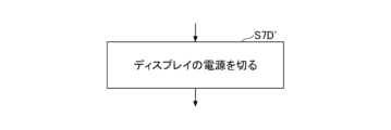
- the input assistance API may turn off the power to the display in standby mode.
- the proximity operation is an operation of bringing the fingertip FT close to the operation surface 105A of the non-contact input device 100 without touching it, and is an operation for switching the display on the display 110 from the standby mode display to the proximity mode display.
- the selection operation is an operation in which, after performing the proximity operation, the fingertip FT is brought even closer to the operation surface 105A of the non-contact input device 100 without touching it, and a GUI button displayed on the display 110 is selected.
- the decision operation is an operation of issuing a click event by bringing the fingertip FT closer to the operation surface 105A of the non-contact input device 100 from the state where the selection operation has been performed, without touching the operation surface 105A of the non-contact input device 100.
- the OS 140 and the application program 160 decide the operation input.
- the decision operation is a non-contact operation input, and is an operation of the non-contact input device 100 without touching the operation surface 105A with the fingertip FT.
- the operation input performed by the non-contact selection operation and decision operation may be called a hover input or a touchless input.
- the fingertip FT touches the operation surface 105A of the non-contact input device 100, it may be treated as a decision mode. Alternatively, when the fingertip FT touches the operation surface 105A of the non-contact input device 100, the input may be confirmed immediately. Alternatively, when the fingertip FT touches the operation surface 105A of the non-contact input device 100, a warning screen may be displayed.
- the display 110 is a liquid crystal display, an organic electroluminescence (EL) display, or the like.
- the display 110 is a display for realizing a GUI (Graphic User Interface).
- the display 110 displays an image (desktop screen, etc.: not shown) provided by a graphical shell of the OS, a second pointer 112 overlaid by the input assistance application 150, and an image 115 of the application software.
- the input assistance application 150 overlays the second pointer 112 by placing it at the top of the Z order (the order closest to the viewpoint).
- the image 115 of the application software includes an image of a GUI button 110A.
- the GUI button 110A is an operation unit, and is shaped like a push button, for example.
- the application software is designed to be operated with a two-dimensional position input device such as a mouse.
- FIG. 1 shows the screen of a restaurant ordering terminal as an example.
- the ordering screen shows a total of 17 GUI buttons 110A, including 8 GUI buttons 110A for menus and 9 GUI buttons 110A in the form of a numeric keypad for numbers, etc.
- the 17 GUI buttons 110A are arranged in 3 or 4 rows in the Y direction and 5 rows in the X direction. The rows extend in the X direction, and Y extends in the column direction.
- the GUI buttons 110A are not limited to those on the screen of a restaurant ordering terminal, and may be other applications as long as they are an operation screen for a touch panel.
- the electrostatic sensor 120 is disposed on top of the display 110, and has a plurality of sensor electrodes 121X extending in the X direction and a plurality of sensor electrodes 121Y extending in the Y direction, as shown in Fig. 2.
- An input sensor circuit 125A is also provided integrally with the electrostatic sensor 120.
- An image display circuit 125B is also provided integrally with the display 110.
- the input sensor circuit 125A is connected between the wirings 122X, 122Y and the control device 130.
- the image display circuit 125B is connected between the display 110 and the control device 130.
- the sensor electrodes 121X, 121Y are connected to the control device 130 via wiring 122X, 122Y and an input sensor circuit 125A.
- Such an electrostatic sensor 120 can be made by forming a transparent conductive film such as ITO (Indium Tin Oxide) on the surface of transparent glass and patterning it into the sensor electrodes 121X, 121Y and wiring 122X, 122Y. The capacitance detected by the electrostatic sensor 120 is input to the control device 130.
- ITO Indium Tin Oxide
- FIG. 2 shows multiple sensor electrodes 121X and multiple sensor electrodes 121Y. Note that it is preferable that the spacing between the sensor electrodes 121X and between the sensor electrodes 121Y is narrower than the spacing between the GUI buttons 110A. In other words, it is preferable to use electrostatic sensors 120 that correspond to the spacing between the GUI buttons 110A.
- the input sensor circuit 125A is mounted on a wiring board.
- the input sensor circuit 125A is provided between the wiring 122X, 122Y and the control device 130, and performs AD (Analog to Digital) conversion of the electrostatic capacitance of the electrostatic sensor 120 acquired by sequentially selecting the multiple wirings 122X and the multiple wirings 122Y.
- the input sensor circuit 125A calculates the XY coordinates of the fingertip FT and a Z value proportional to the electrostatic capacitance value between the operation surface 105A and the fingertip FT from the electrostatic capacitance value of each wiring.
- the input sensor circuit 125A is capable of outputting XY in the same format as a touch-operated digitizer, and is also capable of outputting XYZ in a unique format.
- the input assistance application 150 sends a command to stop the digitizer-format XY output to the input sensor circuit 125A via a coordinate device driver.
- the input assistance application 150 performs processing based on the XYZ output.
- the image display circuit 125B is provided between the display 110 and the control device 130, and displays an image on the display 110 according to image data sent from the control device 130.
- the control device 130 has a control unit 131 and a memory 132.
- the control device 130 is realized by a computer including a central processing unit (CPU), a random access memory (RAM), a read only memory (ROM), an input/output interface, an internal bus, etc.
- the control unit 131 represents the functions of the programs executed by the control device 130 as functional blocks.
- the memory 132 represents the memory of the control device 130 functionally.
- the control unit 131 controls the operation of the non-contact input device 100.
- the control unit 131 receives XY coordinates and Z values input from the input sensor circuit 125A.
- the control unit 131 controls the display of images on the display 110 through the image display circuit 125B.
- the control unit 131 outputs commands corresponding to the operation content determined by the determination operation of the fingertip FT. For example, if the non-contact input device 100 is an ordering terminal in a restaurant, it transmits the name and quantity of the dish ordered by the customer to an order management terminal in the kitchen.
- the control unit 131 has an OS that uses a planar GUI, a coordinate device driver, a display device driver, an input support application, and a specific application program.
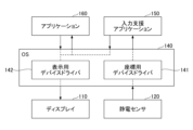
- Figure 4 is used to explain the OS, input support application, and specific application program.
- Figure 4 is a diagram explaining the OS, input support application, and specific application program of the control unit 131.
- FIG. 4 shows the OS 140, input assistance application 150, and application program 160 that the control unit 131 has.
- the OS 140 is an OS (Operating System) that uses a planar GUI such as Windows (registered trademark) or Android (registered trademark).
- An OS that uses a planar GUI does not provide a UI (User Interface) that is suitable for three-dimensional input.
- the application program 160 is an application program such as an ordering terminal at a restaurant.
- the OS 140 has a coordinate device driver 141 and a display device driver 142.
- the coordinate device driver 141 passes the XY coordinates and Z value input from the electrostatic sensor 120 to the input assistance application 150.
- the OS 140 causes the application program 160 to execute a command corresponding to the button on the input XY coordinates.
- the OS 140 passes data of the image to be displayed, the XY position of the image to be displayed, and the Z order of the image to be displayed (order of distance from the viewpoint) to the display device driver 142.
- the input assistance application 150 places the second pointer 112 at the top of the Z order.
- the display device driver 142 performs control to display the second pointer 112 at the XY coordinates input from the input assistance application 150, and control to display an image according to a command input from the application program 160 when a confirmation operation is performed.
- the OS treats the second pointer 112 simply as an image.
- the input assistance application 150 is an application that provides input assistance to a user who uses the non-contact input device 100.
- the input assistance application 150 may perform processing to calculate an index of the positional accuracy of the fingertip FT.
- the input assistance application 150 performs processing to cause the OS 140 to display an image of the second pointer 112, which is different from the first pointer 111 that the OS 140 displays on the display 110, based on the XY coordinates of the fingertip FT and the index of positional accuracy.
- the input assistance application 150 outputs the XY coordinates at the time of the confirmation operation to the OS 140 as the position of the mouse pointer, and then issues a click event.
- the OS 140 notifies the application program 160 that the GUI button corresponding to the position of the mouse pointer when the click event is issued has been pressed. Other processing performed by the input assistance application 150 and details of each processing will be described later.
- Application program 160 is designed to be operated with a normal mouse (which outputs two-dimensional coordinates) or a touch panel.
- OS 140 When application program 160 is notified by OS 140 that a click event has been issued on a GUI button, it performs processing according to the GUI button that was clicked.
- the display 110, control device 130, OS 140, display device driver 142, and application program 160 may be existing devices that do not support three-dimensional input (non-contact input).
- the existing device becomes a non-contact input device.
- the input sensor circuit 125A scans the sensor electrodes 121X row by row and the sensor electrodes 121Y column by column, and converts the capacitances at the intersections between the sensor electrodes 121X and the sensor electrodes 121Y into digital values.
- the control unit 131 counts the change in the output of the digital value of the capacitance and calculates a difference value ⁇ AD at each intersection.
- the difference value ⁇ AD is a count value of the change in the output of the input sensor circuit 125A relative to a reference value.
- the reference value is a value proportional to the capacitance of each intersection of the sensor electrodes 121X and 121Y when there is no target such as a fingertip FT around the sensor electrodes 121X and 121Y.
- the input sensor circuit 125A calculates the XY coordinates on the display facing the fingertip FT from the difference values at each intersection, and selects the maximum ⁇ AD of the difference values ⁇ AD at each intersection as the Z value.
- the Z value is a value proportional to the capacitance between the fingertip FT and the operation surface.
- the XY coordinates and the Z value may be calculated by the control unit 131.
- the coordinate device driver 141 may calculate the XY coordinates and the Z value.
- the hardware that performs the calculation is the control unit 131.
- the input assistance application 150 obtains an index of the positional accuracy of an object when displaying the second pointer 112 on the display 110.
- the object is an object for which the XY coordinates and the distance in the Z direction from the operation surface 105A are obtained based on the electrostatic capacitance with the electrostatic sensor 120, and is a part of the body such as the hand or fingertip of the user of the non-contact input device 100.
- the index of the positional accuracy of the object will be described.
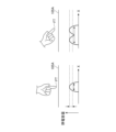
- FIGS. 5A and 5B are diagrams explaining an index of the positional accuracy of an object.
- the non-contact input device 100 uses the amount of variation in the XY coordinates (two-dimensional position) of the fingertip FT as an index of the positional accuracy of the object.
- FIG. 5A shows an example of the distribution of capacitance in the X direction measured at times t1 and t2. Assume that the X coordinate of the fingertip FT at time t1 is calculated as X1, and the X coordinate of the fingertip FT at time t2 is calculated as X2.
- the non-contact input device 100 uses the amount of fluctuation in coordinates measured within a certain period of time as an index of positional accuracy. More specifically, it uses the standard deviation of the measured coordinates as an index of positional accuracy. For example, if the second pointer 112 is a circle with a radius of 1 ⁇ of the standard deviation, the probability that a finger is inside the second pointer 112 is approximately 68%, and if the second pointer 112 is a circle with a radius of 2 ⁇ , the probability that a finger is inside the second pointer 112 is approximately 95%. In this way, by expressing the positional accuracy as the size of the pointer, it is possible to intuitively provide feedback of the positional accuracy to the user.
- Figure 5B shows an example of the capacitance distribution in the X direction when a fingertip FT is held upright against operation surface 105A and is gradually brought closer to operation surface 105A.
- the fingertip FT on the left side in Figure 5B is the furthest from operation surface 105A, and the fingertip FT on the right side in Figure 5B is the closest to operation surface 105A.
- the double arrows in Figure 5B indicate the range in which capacitance is detected. Note that although Figure 5B shows the capacitance distribution in the X direction, as explained in Figure 5C, the capacitance distribution in the Y direction is similar due to symmetry.
- the electrostatic sensor 120 is affected by the fingertip FT over a wide range, resulting in a flat capacitance distribution. If the magnitude of the noise is the distance between the two dotted lines, the range that can be detected as the X coordinate of the fingertip FT is the range where the capacitance is greater than the lower dotted line. In other words, the range in the X direction where the fingertip FT can be detected is the wide range shown by the left and right arrows.
- the electrostatic sensor 120 is affected by the fingertip FT in a narrow range, resulting in a steep distribution of capacitance. If the magnitude of the noise is the distance between the two dotted lines, the range that may be detected as the X coordinate of the fingertip FT is the range where the capacitance is greater than the lower dotted line. In other words, the range in the X direction where the fingertip FT may be detected is the narrow range shown by the left-right arrows.
- the distribution of capacitance in the X direction is intermediate between the gradual distribution on the left side and the steep distribution on the right side.
- the range in which the measured XY coordinates fluctuate due to noise is greater when the fingertip FT is farther from the operation surface 105A (left side) than when the fingertip FT is closer to the operation surface 105A (right side).
- Figure 5C shows an example of the capacitance distribution in the X direction when the fingertip FT is operated upright on the operation surface 105A (left side) and when the fingertip FT is operated horizontally on the operation surface 105A (right side).
- the double arrows indicate the range in which the capacitance is detected. Note that although Figure 5C shows the capacitance distribution in the X direction, the capacitance distribution in the Y direction is similar.
- the amount of variation in the measured XY coordinates due to noise is greater when the fingertip FT is laid down as shown on the right side of Figure 5C than when the fingertip FT is placed upright as shown on the left side of Figure 5C.
- the amount of variation in the measured XY coordinates due to noise varies depending on the distance from fingertip FT to operation surface 105A, the orientation of fingertip FT, and the like. Furthermore, the amount of variation also varies depending on the magnitude of noise. The amount of variation also increases when fingertip FT is actually moved. If the amount of variation increases for any reason, the measurement accuracy is poor, so the second pointer 112 is displayed larger. If the amount of variation decreases, the second pointer 112 is displayed smaller. In this way, the position accuracy is represented by the size of the second pointer, and the position accuracy can be intuitively fed back to the user.
- the non-contact input device 100 may determine that the fingertips FT are not held upright near the operation surface 105A and may display a message encouraging the user to hold the fingertips FT upright near the operation surface 105A.
- the input assistance application 150 calculates the moving average of the X coordinates acquired at multiple time points and the moving average of the Y coordinates acquired at multiple time points as the XY coordinates of the fingertip FT.
- the multiple time points are the most recent time points for calculating the moving average, and the interval between the time points is several milliseconds.
- the input assistance application 150 outputs a command to the OS 140 to display an image of the second pointer at the XY coordinates calculated as the moving average.
- the XY coordinates of the fingertip FT detected by the non-contact input device 100 using the electrostatic sensor 120 represent, as an example, the XY coordinates of the position with the largest capacitance in the area where the fingertip FT exists.
- the center of gravity of a figure consisting of multiple points whose difference from the largest capacitance is equal to or less than a threshold value may be regarded as the XY coordinates of the fingertip FT.
- the X coordinate (or Y coordinate) of the apex obtained by fitting the position with the largest capacitance and the capacitance of the three points adjacent to it in the X direction (or Y direction) to a quadratic curve may also be regarded as the X (Y) coordinate of the fingertip FT.
- the capacitance is inversely proportional to the distance. Since the capacitance and the distance correspond one-to-one, the capacitance can be used instead of the distance. Furthermore, in the non-contact input device 100 of the present invention, the unit of capacitance does not need to be expressed in farads [F]. In the present invention, a value proportional to the capacitance is called a Z value.
- the input sensor circuit 125A is designed to have a Z value of approximately 100 when the fingertip FT is in contact with the operation surface 105A, and a Z value of approximately 0 when the fingertip FT is not near the operation surface 105A.
- the input assistance application 150 may stop calculating the moving average of the XY coordinates or the amount of fluctuation in the XY coordinates.
- the display In the standby mode, the display may be turned off.
- the input assistance application 150 calculates the standard deviation of the XY coordinates as an index of the positional accuracy of the target object. A method for calculating the standard deviation of the XY coordinates will be described later with reference to FIG. 9D.
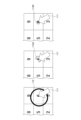
- 6A to 6F are diagrams showing an example of the display on the display 110 of the non-contact input device 100.
- the display 110 and the operation surface 105A are shown overlapping each other.
- the display on the display 110 is visible to the user through the operation surface 105A.
- Fig. 6C to Fig. 6F show a part of the image displayed on the display 110.
- FIG. 6A shows the display of the display 110 in standby mode.
- messages such as "Touchless operation is possible” and "Please place your finger on the screen” are displayed. This allows the user to guide the fingertip FT to the operation surface 105A even if it is their first time using the non-contact input device 100, leading to smooth use thereafter.
- FIG. 6B shows an example of a message in the proximity mode.
- the messages "The pointer will shrink depending on the position accuracy” and "If the pointer is too large, move your finger closer or hold it up” are displayed.
- a second pointer 112 is displayed on the display 110. Note that the pointer is a figure or symbol that indicates the current input position on the screen (image) displayed on the display 110.
- the second pointer 112 is a figure that the input assistance application 150 causes the OS 140 to display.
- the input assistance application 150 hides the first pointer (mouse pointer) 111 prepared by the OS.
- the second pointer 112 may be a circular or elliptical figure, in addition to the annular figure shown in FIG. 6B.
- the input assistance application 150 increases the radius of the second pointer 112 as the amount of variation in the XY coordinates, which is an index of positional accuracy, increases, and decreases the radius of the second pointer 112 as the amount of variation in the XY coordinates decreases.
- the input assistance application 150 causes the display 110 via the OS 140 to display a second pointer 112 with a larger radius as the amount of variation in the XY coordinates increases, and causes the display 110 via the OS 140 to display a second pointer 112 with a smaller radius as the amount of variation in the XY coordinates decreases.
- FIG. 6C a more specific operation will be described when the user brings fingertip FT closer to operation surface 105A to select the GUI button with the number 6 in selection mode.
- first pointer 111 is hidden, so only second pointer 112 is shown.
- second pointer 112 which has a circular shape, is displayed.
- the input assistance application 150 causes the OS 140 to display a second pointer 112 whose radius increases as the amount of variation in the XY coordinates increases. For example, when the fingertip FT is farther from the operation surface 105A, the amount of variation in the XY coordinates increases.
- the input assistance application 150 causes the OS 140 to display a second pointer 112 with a smaller radius as the amount of variation in the XY coordinates decreases. For example, when the fingertip FT is closer to the operation surface 105A, the amount of variation in the XY coordinates becomes smaller.
- the non-contact input device 100 can intuitively feed back the position accuracy to the user.
- FIG. 6D illustrates the operation when the user holds the fingertip FT close to the operation surface 105A in order to confirm the operation input of the GUI button number 6 in the confirmation mode.
- the second pointer 112A has a different display color from the second pointer 112 shown in FIG. 6C. For this reason, the second pointer 112A is shown with a double line in FIG. 6C.
- the input assistance application 150 intuitively indicates that the input mode has changed by changing the circular shape of the second pointer 112 to the arc of the second pointer 112A.
- the input assistance application 150 can emphasize the change in the input mode by changing the color of the second pointer 112 from red (112) to yellow (112A). Note that the color of the second pointer is not limited to being changed from red to yellow.
- the color of the second pointer (112, 112A) may be changeable on a setting screen described later. Instead of changing the color, the brightness may be changed, or both the color and the brightness may be changed.
- Figure 6D shows how the images change over time, starting from the top left, followed by the arrows, then to the top right, bottom left, and bottom right.
- an arc-shaped second pointer 112A is displayed as shown in the upper left, and as the fingertip FT is held close to the operation surface 105A, the arc extends as shown in the upper right, and then the arc of the second pointer 112A extends further as shown in the lower left.
- the second pointer 112A becomes a ring.
- the operation content is decided. That is, the operation content is decided by continuing to point the number 6 with the fingertip FT until the second pointer 112A becomes a ring. In this way, the non-contact input device 100 allows the user to perform a non-contact click operation instead of touching the operation surface 105A.
- the input assistance application 150 outputs a click event.
- the input assistance application 150 issues the same event as when a mouse is clicked, by inputting an operation with the fingertip FT without contact.
- the input assistance application 150 outputs the X and Y coordinates of the fingertip FT to the OS 140, and outputs a click event.
- the input assistance application 150 may also cause the OS 140 to play a click event output sound. Such output of the X and Y coordinates without contact and output of the click event corresponds to the operation of touching the GUI button 110A on the operation surface 105A.
- the input assistance application 150 When the input assistance application 150 outputs a click event, it displays a circular second pointer 112B with a smaller radius than the annulus for a predetermined period of time (e.g., about 1 to 2 seconds) as shown in the lower right of Figure 6D.
- a predetermined period of time e.g., about 1 to 2 seconds
- the circular second pointer 112B is displayed for the user's confirmation at the XY coordinates (moving average) of the fingertip FT when the operation input is confirmed.
- the second pointer 112B is displayed for a predetermined time (about 1 to 2 seconds) and becomes invisible when the predetermined time has elapsed.
- the second pointer 112B may have a display color different from the second pointers 112 and 112A.
- the input assistance application 150 intuitively indicates that the operation input has been confirmed by changing the second pointer 112B to a small circle immediately after the central angle of the second pointer 112A (arc) reaches 360 degrees. Furthermore, by changing the color, it is possible to emphasize that the operation input has been confirmed. Also, instead of changing the color, the brightness may be changed, or both the color and the brightness may be changed.
- FIG. 6C and 6D show an example in which the first pointer 111 of the OS 140 is erased, but as shown in FIG. 6E, both the first pointer 111 (mouse pointer) of the OS 140 and the second pointer 112 (pointer for a non-contact input device) of the input assistance application 150 may be displayed.
- the input assistance application 150 continues to output XY coordinates to the OS 140 in the selection mode and decision mode described below.
- the first pointer 111 performs the same function as a reticle that indicates the position of the XY coordinates with high precision.
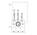
- Fig. 6F shows the function menu 112C.
- the input assistance application 150 causes the OS 140 to display the function menu 112C.
- This predetermined time is an example of a third predetermined time.
- Fig. 6E shows, as an example, the function menu 112C from which a click mode, a drag mode, and a pinch-in can be selected.
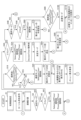
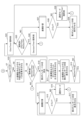
- FIGS. 7A to 7C, 8A to 8F, and 9A to 9F are diagrams showing an example of processing executed by the input assistance application 150 of the non-contact input device 100.
- Figures 7A to 7C show an example of main processing
- Figure 7D shows an example of a modified example of the processing shown in Figure 7C
- Figures 8A to 8F and 9A to 9F show an example of subroutine processing.
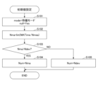
- Step S1 is a subroutine, the details of which will be described later with reference to FIG. 8A, and sets initial values such as the number of data Nma for calculating the moving average.
- the input assistance application 150 outputs a command to erase the first pointer 111 to the OS 140 (step S2). This causes the first pointer 111 to be erased from the display 110.
- the first pointer 111 (mouse pointer) may be displayed without performing the processing of step S2 (see FIG. 6E). In this case, both the first pointer 111 and the second pointer 112 will be displayed.
- the input assistance application 150 continues to output the XY coordinates of the fingertip FT to the OS. Since the position of the first pointer 111 and the center of the second pointer 112 coincide, it becomes easier to see the center of the second pointer 112 even if it is a large circle.
- the input assistance application 150 calculates the XY coordinates of the fingertip FT (step S3).
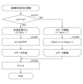
- Step S3 is a subroutine, the details of which will be described later, but it uses the XY coordinates of the fingertip FT calculated at multiple points in time to calculate a moving average of the XY coordinates of the fingertip FT.
- the input assistance application 150 determines whether the mode of the input assistance application 150 is the decision mode (step S4). To make the explanation easier to understand, the case where the mode of the input assistance application 150 is the decision mode will be explained first.
- the input assistance application 150 determines whether the mode of the input assistance application 150 is the decision mode (S4: YES), it determines whether the Z value is greater than Cz1 (step S5). If the Z value is greater than Cz1, the input assistance application 150 considers that the distance from the operation surface 105A to the fingertip FT is shorter than the first threshold value Z1. The input assistance application 150 determines from the Z value whether the fingertip FT is located within the decision area.
- the input assistance application 150 determines that the Z value is greater than Cz1 (S5: YES), it sets SelectionOffTime and ProximityOffTime to the current time (step S6).
- SelectionOffTime is updated to the time when it was determined that the Z value was greater than Cz1.
- SelectionOffTime indicates the last time when the Z value was determined to be greater than Cz1.
- ProximityOffTime is also updated when it is determined that the Z value is greater than Cz2.
- ProximityOffTime indicates the last time when the Z value was determined to be greater than Cz2.
- the input assistance application 150 determines whether DecisionTH is 0 (S7).
- DecisionTH is a value that can be set by the user. If DecisionTH is 0, the input is confirmed immediately upon entering decision mode, without displaying the arc cursor described below. On the other hand, if DecisionTH is other than 0, the input is confirmed after displaying the arc cursor described below.
- the input assistance application 150 determines that DecisionTH is not 0 (S7: No), it outputs to the OS 140 a command to display the second pointer 112A in an arc shape at the XY coordinates (moving average: Xave, Yave) calculated in step S3 (step S8).
- the command output to the OS 140 in step S8 is a command to display an arc with a radius of a predetermined value (fixed value) centered on the XY coordinates (moving average).
- the arc is an arc whose moving end extends clockwise relative to the fixed end, the fixed end is located at a position corresponding to 12 o'clock on the clock, and the moving end extends clockwise from 12 o'clock.
- DecisionTime is the time when drawing of the arc begins
- DecisionTH is the time required from when drawing of the arc begins until a click event is output.
- a click event is an event that occurs when the operation content is decided by an operation input with fingertip FT.
- the operation content is decided when second pointer 112A changes from an arc to a ring.
- input assistance application 150 outputs a click event.
- the user can decide the operation content by bringing fingertip FT close to operation surface 105A within the decision area and holding fingertip FT until second pointer 112A extends to become a ring.
- the input assistance application 150 determines whether the current time - DecisionTime > DecisionTH is true (step S9). In other words, it determines whether the time that has elapsed since the time (DecisionTime) when the mode transitioned to the decision mode has exceeded DecisionTH. This is to determine whether the operation content has been decided, and whether to output a click event that is performed when the operation content has been decided.
- the time that has elapsed since the time (DecisionTime) when the mode transitioned to the decision mode is an example of a first predetermined time.
- step S9 NO
- the input assistance application 150 determines that the current time - DecisionTime > DecisionTH is not true (S9: NO)
- it returns the flow to step S3.
- the processing of steps S3 to S8 is repeated, causing the arc to grow.
- the input assistance application 150 determines that Current Time - DecisionTime > DecisionTH is true (S9: YES), it proceeds with the process to output a click event.
- Current Time - DecisionTime > DecisionTH is true, the arc cursor becomes a ring.
- the input assistance application 150 erases the second pointer 112A (step S10).
- the input assistance application 150 outputs the XY coordinates (moving averages) calculated in step S3 to the OS 140, and then outputs a click event to the OS 140. Furthermore, the input assistance application 150 causes the OS 140 to play a click event output sound (step S11). This causes the click event output sound to be output from the speaker. Furthermore, when the XY coordinates overlap with the GUI button 110A of the application program 160 and a click event is issued, the application program 160 executes the process indicated by the GUI button 110A.
- step S11 If the input assistance application 150 determines that DecisionTH is 0 (S7: Yes), it executes the process of step S11 described above. That is, if the input assistance application 150 determines that DecisionTH is 0 (S7: Yes) or if it determines that "current time - DecisionTime > DecisionTH" is true (S9: YES), it outputs the XY coordinates and the click event to the OS 140 and causes the OS 140 to play the click event output sound.
- the input assistance application 150 causes the OS 140 to display the second pointer 112B centered on the XY coordinates (moving average) calculated in step S3 for a predetermined period of time (step S12).
- the center of the second pointer 112B is the XY coordinates (moving average) calculated in step S3.
- the specified time is, for example, about 1 to 2 seconds, and when the specified time has elapsed, the second pointer 112B becomes hidden.
- ReClickTH is the time (click re-output time) until the second pointer 112A starts to be displayed again if the fingertip FT continues to be located within the decision area after a click event is output.
- the user of the non-contact input device 100 can set ReClickTH for the input assistance application 150 via the setting screen displayed on the display 110.
- the input assistance application 150 determines whether the Z value is greater than Cz1 (step S15). After the operation content is determined, the input assistance application 150 determines whether the fingertip FT continues to be located within the determination area.
- step S16 If the input assistance application 150 determines that the Z value is not greater than Cz1 (S15: NO), it sets the selection mode (step S16). Then, the flow returns to step S3. If the Z value ⁇ AD is not greater than Cz1, this is the case when the fingertip FT has moved from the decision area to the selection area, the proximity area, etc. When the fingertip FT has moved from the decision area to the selection area, the proximity area, etc., the process of step S14 is provided to enable re-input.
- step S15 If the input assistance application 150 determines in step S15 that the Z value is greater than Cz1 (S15: YES), it causes the OS 140 to display the second pointer 112B at the XY coordinate (moving average) calculated in step S14 (step S17).
- the size of the circular second pointer 112B is a predetermined value.
- the input assistance application 150 will not re-output the click event unless the mode is changed from the decision mode to another mode, and will continue to display the second pointer 112B at the XY coordinate position of the fingertip FT.
- the input assistance application 150 When the input assistance application 150 finishes processing in step S17, it returns the flow to S14. If the operation content is decided as a result of YES in step S7 or YES in step S9, and the fingertip FT continues to be within the decision area after the second pointer 112B is displayed in step S12, the input assistance application 150 displays the second pointer 112B in step S17 and then returns the flow to step S14. In other words, the second pointer 112B continues to be displayed while updating its position. To decide the next operation content after the operation content has been decided once, it is sufficient to move the fingertip FT out of the decision area once.
- step S5 determines whether or not the relationship Current time - SelectionOffTime > SelectionOffTH is established (step S18). That is, when the fingertip FT is continuously positioned outside the decision area, it determines whether or not the elapsed time from the time (SelectionOffTime) when it was last determined that the fingertip FT was positioned within the decision area exceeds SelectionOffTH. This elapsed time is an example of a fourth predetermined time.
- SelectionOffTH is the time it takes to transition from decision mode to selection mode when the fingertip FT is moved into the selection area.
- the user of the non-contact input device 100 can set SelectionOffTH for the input assistance application 150 through a setting screen displayed on the display 110. Note that the time when the fingertip FT was last determined to be located within the decision area is the most recent time when the fingertip FT was determined to be located within the decision area.
- the input assistance application 150 determines whether the Z value is greater than Cz2 (step S19). If the Z value is greater than Cz2, the input assistance application 150 determines that the fingertip FT is staying in the first area. If Z is greater than Cz2 (S19: YES), the flow returns to step S7. As a result, operation in the decision mode continues. The Z value does not use a moving average, and a value smaller than the actual value may be measured due to noise. In other words, even if the fingertip FT is located in the decision area, there are cases where Z>Cz1 is not true (S5: NO).
- the input assistance application 150 sets the selection mode and sets SelectionTime to the current time (step S20). If the Z value is not greater than Cz2, the fingertip FT is considered not to be in the decision area.
- the input assistance application 150 determines that the current time - SelectionOffTime > SelectionOffTH is true (S18: YES), it sets the mode of the input assistance application 150 to the selection mode and sets SelectionTime to the current time (step S20). If the state in which the Z value is not greater than Cz1 (step S5) continues longer than SelectionOffTH, it considers that the fingertip FT is not in the decision area.
- the input assistance application 150 causes the OS 140 to hide the second pointer 112A (step S21).
- the input assistance application 150 displays the second pointer 112 on the OS 140 (step S22).
- the second pointer 112 is the second pointer for the selection mode shown in FIG. 6C.
- the input assistance application 150 hides the second pointer 112A.
- the center of the second pointer 112 is the XY coordinates (moving average) of the fingertip FT, and the radius of the second pointer 112 is a radius corresponding to the amount of fluctuation in the XY coordinates.
- the input assistance application 150 when displaying the second pointer 112 on the OS 140, the input assistance application 150 outputs the position of the second pointer 112 corresponding to the XY coordinates (moving average) of the fingertip FT to the OS 140.
- the input assistance application 150 sets the size of the second pointer 112 to a size corresponding to the amount of fluctuation in the XY coordinates.
- the input assistance application 150 executes a process for determining whether or not the function menu needs to be displayed (step S23).
- the process for determining whether or not the function menu needs to be displayed is a subroutine process, and will be described in detail later. After completing the process of step S23, the input assistance application 150 returns the flow to step S3.
- the input assistance application 150 determines whether current time - ClickTime > ReClickTH is true (step S25).
- step S26 the input assistance application 150 sets DecisionTime to the current time (step S26). Then, the flow returns to step S3. DecisionTime becomes the time when the flow returns to step S3.
- the time from when a click event is output until the drawing of the second pointer 112A (arc) starts again is the "predetermined time" in step S12 plus ReClickTH. It takes DecisionTimeTH from when the drawing of the second pointer 112A (arc) starts until the second pointer 112A becomes a ring.
- a click event is output every time the "predetermined time” in step S12 plus ReClickTH and DecisionTimeTH has elapsed.
- the second predetermined time is the sum of the "predetermined time” in step S12, ReClickTH, and DecisionTimeTH.
- step S27 If the input assistance application 150 determines in step S25 that the current time - ClickTime > ReClickTH is not true (S25: NO), it calculates the X and Y coordinates of the fingertip FT (step S27). Like step S3, step S27 is a subroutine, the details of which will be described later, but it uses the X and Y coordinates of the fingertip FT calculated at multiple points in time to calculate a moving average of the X and Y coordinates of the fingertip FT.
- the input assistance application 150 determines whether the Z value is greater than Cz1 (step S28). This is to determine whether the fingertip FT is located within the decision area.
- the input assistance application 150 determines that the Z value is greater than Cz1 (S28: YES), it displays the second pointer 112B at a position centered on the XY coordinates of the fingertip FT (step S29). If the input assistance application 150 remains in the decision mode, it causes the OS 140 to display the second pointer 112B until the click re-output time (ReClickTH) has elapsed.
- ReClickTH click re-output time
- step S27 If the input assistance application 150 determines in step S27 that the Z value is not greater than Cz1 (S28: NO), it sets the mode of the input assistance application 150 to the selection mode and sets the current time to SelectionTime (step S30).
- the mode When the fingertip FT moves from the decision area to the selection area, the mode immediately transitions to the selection mode. A user who wishes to perform the next operation input as soon as possible can switch to the selection mode by slightly removing the fingertip FT from the operation surface 105A.
- the input assistance application 150 finishes the processing of step S30 it returns the flow to step S3.
- step S4 determines whether the mode is not the decision mode (S4: NO). That is, the input assistance application 150 determines whether the fingertip FT is located within the decision area. If the Z value is greater than Cz1, the fingertip FT is located within the decision area.
- the input assistance application 150 determines that the Z value is greater than Cz1 (S4A: YES), it sets SelectionOffTime and ProximityOffTime to the current time (present time) (step S5A).
- SelectionOffTime is updated to the time when it is determined that the Z value is greater than Cz1, so SelectionOffTime indicates the last time when the Z value was determined to be greater than Cz1.
- ProximityOffTime is also updated when it is determined that the Z value is greater than Cz2. Therefore, ProximityOffTime indicates the last time when the Z value was determined to be greater than Cz2.
- the input assistance application 150 sets DecisionTime to the current time (step S6A).
- the input assistance application 150 outputs a click event. Since it was determined in step S4 that the decision mode was not in effect and then in step S4A that the Z value is greater than Cz1, the time at which step S6A is executed is the time at which the decision mode was in effect. In other words, the DecisionTime set in step S6A is the time at which the decision mode was in effect.
- the input assistance application 150 sets the mode of the input assistance application 150 to the decision mode (step S7A). Furthermore, the input assistance application 150 erases the second pointer 112 for the selection mode (step S8A). After completing the processing of step S8A, the flow proceeds to step S7.
- the mode immediately transitions to decision mode.
- the fingertip FT moves away from the operation surface 105A, the mode is not changed immediately.
- the Z value becomes small (when the state in which the fingertip FT moves away from the operation surface 105A is measured)
- the mode is not changed immediately, thereby stabilizing the operation.
- the mode without using a moving average for the Z value, when the fingertip FT approaches the operation surface 105A, the mode immediately transitions to decision mode, thereby realizing quick operation.
- step S4A determines whether the input assistance application 150 is in the selection mode (step S4B).
- the input assistance application 150 determines whether the Z value is greater than Cz2 (step S5B). In other words, the input assistance application 150 determines whether the fingertip FT is located within the selection area.
- the input assistance application 150 determines that the Z value is greater than Cz2 (S5B: YES), it sets ProximityOffTime to the current time (step S6B).
- ProximityOffTime is the time when the fingertip FT was last determined to be located within the selection area when it has been continuously located within the selection area.
- ProximityOffTime is updated, so that ProximityOffTime becomes the most recent time when the fingertip FT was determined to be located within the selection area.
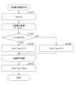
- the input assistance application 150 executes a second pointer radius setting process that sets the radius of the second pointer 112 according to the amount of variation in the X and Y coordinates (step S7B).
- the second pointer radius setting process is a subroutine process and will be described in detail later, but in the selection mode, the radius of the second pointer 112 (see FIG. 6C) is set according to the amount of variation in the X and Y coordinates.
- the input assistance application 150 advances the flow to step S21 and causes the second pointer 112 to be displayed on the OS 140.
- step S5B determines whether or not the current time-ProximityOffTime>ProximityOffTH is satisfied (step S8B). That is, when the fingertip FT is continuously located within the selection area, it determines whether or not the elapsed time from the time (ProximityOffTime) when it was last determined that the fingertip FT was located within the selection area exceeds ProximityOffTH.
- ProximityOffTH is the time until the transition from the selection mode to the proximity mode.
- the user of the non-contact input device 100 can set ProximityOffTH for the input assistance application 150 through the setting screen displayed on the display 110.
- the input assistance application 150 determines that the current time - ProximityOffTime > ProximityOffTH is not true (S8B: NO), it executes a second pointer radius setting process to set the radius of the second pointer 112 according to the amount of fluctuation in the X and Y coordinates (step S9B).
- the second pointer radius setting process is a subroutine process and will be described in detail later, but in the selection mode, the radius of the second pointer 112 (see FIG. 6C) is set according to the amount of fluctuation in the X and Y coordinates.
- the input assistance application 150 advances the flow to step S21 and causes the second pointer 112 to be displayed on the OS 140.
- the Z value does not use a moving average, and a smaller value than the actual value may be measured due to noise.
- a state in which Z > Cz2 is not true even though the actual position of the fingertip FT is in the selection area is resolved in a time shorter than ProximityOffTH. Therefore, even if a small Z value is measured due to noise while the second pointer 112 is displayed, the display of the second pointer 112 continues.
- the processing from S8B: NO to S9B can stabilize the operation without reducing the sensory reaction speed.
- step S8B If the input assistance application 150 determines in step S8B that (current time - ProximityOffTime > ProximityOffTH) is true (S8B: YES), it sets the mode of the input assistance application 150 to the proximity mode (step S10B).
- the input assistance application 150 causes the OS 140 to display an image and a message for the proximity mode (see FIG. 6B) (step S11B). As a result, as shown in FIG. 6B, the image and the message for the proximity mode are displayed on the display 110. After completing the processing of step S11B, the input assistance application 150 advances the flow to step S3.
- step S4B determines whether the mode of the input assistance application 150 is not the selection mode (S4B: NO). That is, the input assistance application 150 determines whether the fingertip FT has entered the selection area again.
- the input assistance application 150 determines that the Z value is greater than Cz2 (S4C: YES), it sets ProximityOffTime to the current time (step S5C). As described above, if Z>Cz1 (S5 or S4A) is YES, or Z>Cz2 (S5B or S4C) is YES, ProximityOffTime is updated to the current time. Thus, the last time when Z was greater than Cz2 is stored as ProximityOffTime.
- the input assistance application 150 sets the mode of the input assistance application 150 to the selection mode and sets SelectionTime to the current time (step S6C).
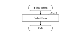
- the input assistance application 150 performs a process of setting the radius of the second pointer 112 to an initial value (step S7C).
- the process of setting the radius of the second pointer 112 to an initial value is a subroutine process, so the details will be described later, but this process sets the radius of the second pointer 112 to an initial value, not a radius according to the amount of variation in the XY coordinates.
- the input assistance application 150 advances the flow to step S21 and displays the second pointer 112 on the OS 140. Note that although the fingertip FT is actually in the proximity area, noise may cause the Z value to be measured as larger than it actually is, and the selection mode may be entered.
- the selection mode is entered when the fingertip FT is relatively close, most users do not recognize this as a malfunction. Conversely, if the fingertip FT is in a distant position (standby area), the selection mode will not be entered even if a noise level that is normally present is present.
- step S4C determines whether the mode of the input assistance application 150 is the proximity mode (step S4D).
- the input assistance application 150 determines whether the Z value is greater than Cz3 (step S5D). If the Z value is greater than Cz2, the input assistance application 150 considers the distance from the operation surface 105A to the fingertip FT to be shorter than the third threshold value Z3.
- step S11B an image and a message for the proximity mode are displayed on the display 110, as shown in FIG. 6B.
- step S5D determines in step S5D that the Z value is not greater than Cz3 (S5D: NO), it sets the mode of the input assistance application 150 to the standby mode (step S6D). If the Z value is not greater than Cz3, the input assistance application 150 considers that the distance from the operation surface 105A to the fingertip FT is longer than the third threshold value Z3.
- the input assistance application 150 causes the OS 140 to display an image and a message for the standby mode (step S7D). As a result, the image and the message for the standby mode are displayed on the display 110. After completing the process of step S7D, the input assistance application 150 advances the flow to step S3. Note that in the standby mode, the display may be powered off (S7D' in FIG. 7D).
- step S4D determines whether the mode of the input assistance application 150 is not the proximity mode (S4D: NO).
- the input assistance application 150 determines whether the Z value is greater than Cz3 (step S4E).
- the input assistance application 150 determines whether the fingertip FT has entered the proximity region again.
- the input assistance application 150 determines that the Z value is greater than Cz3 (S4E: YES), it sets the mode of the input assistance application 150 to the proximity mode (step S5E). The input assistance application 150 proceeds to step S11B and displays an image and a message for the proximity mode.
- step S4E determines in step S4E that the Z value is not greater than Cz3 (S4E: NO)
- the flow proceeds to step S7D.
- the input assistance application 150 since the input assistance application 150 is in standby mode, an image and message for standby mode are displayed on the display 110 in step S7D.
- the input assistance application 150 repeatedly executes the main flow. Next, each subroutine will be explained.
- ⁇ FIG. 8A Initial value setting>
- the input support application 150 sets the mode of the input support application 150 to a standby mode, and sets the flag null to YES (step S101).
- the input assistance application 150 sets Nma to a predetermined integer (step S102).
- the predetermined integer is obtained as int (MATime/Nmea).
- int (MATime/Nmea) represents an integer obtained by rounding down the decimal point of MATime/Nmea.
- the user of the non-contact input device 100 can set MATime for the input assistance application 150 through a setting screen displayed on the display 110.
- the input assistance application 150 compares Nma and Ndev to determine which is larger (step S103).
- Ndev is the number of multiple data items used when calculating the position accuracy index.
- the input assistance application 150 sets the number of arrays Num to the larger of Nma and Ndev (steps S104 and S105). In other words, the larger of the "number of data required to calculate the moving average" and the “number of data required to calculate the position accuracy index” is set to the number of arrays Num. Since the number of elements in the array is determined, the array may be declared at this stage. After completing the processing of step S104, the input assistance application 150 ends the initial value setting subroutine.
- the input assistance application 150 acquires the XY coordinates and the Z value from the input sensor circuit 125A (step S111).
- the input assistance application 150 obtains the current time from the OS 140 (step S112).
- the "current time” used in the main loop described above uses the value obtained in step S112.
- the input assistance application 150 updates the array of X coordinates (step S113). Since step S113 is a subroutine process, details will be described later, but in step S113, the input assistance application 150 removes the oldest value from the array used to calculate the moving average of the X coordinates and the index of positional accuracy, and adds the latest value.
- the input assistance application 150 updates the Y coordinate array (step S114). Since step S113 is a subroutine process, details will be described later, but in step S114, the input assistance application 150 removes the oldest value from the array used to calculate the moving average of the Y coordinate and the position accuracy index, and adds the latest value.
- the input assistance application 150 calculates the moving average from the array of X coordinates updated in step S113 (step S115).
- the input assistance application 150 calculates the moving average of the array of Y coordinates updated in step S114 (step S116).
- the input assistance application 150 determines whether the Z value acquired in step S111 is greater than Cz3 (step S117). If the Z value is not greater than Cz3, the Z value is within the waiting area, and the reliability of the latest XY coordinate acquired in step S111 and the XY coordinates acquired in step S111 before that is low, and they are not suitable coordinate values for calculating the moving average of the XY coordinates, so the process of step S117 is provided.
- step S111 determines that the Z value acquired in step S111 is greater than Cz3 (S117: YES)
- step S111 determines that the Z value acquired in step S111 is not greater than Cz3 (S117: NO)
- it sets the flag null to YES (step S119). Since the latest XY coordinates are not suitable for calculating the moving average of the XY coordinates, it sets the flag null to YES.
- FIG. 8C Updating the X-coordinate array>
- Fig. 8C shows details of the subroutine process for updating the X-coordinate array in step S113 in Fig. 8B.
- multiple X-coordinates acquired at multiple points in time are distinguished as X(i).
- the multiple X-coordinates X(i) were acquired at different times, and are multiple X-coordinates acquired continuously by the non-contact input device 100 at a predetermined sampling period.
- i 1 to Num
- X(1) is the latest X-coordinate.
- the input assistance application 150 determines whether the null flag is YES (step S121X). This is to determine whether the latest X coordinate is appropriate.
- the input assistance application 150 determines that the null flag is YES (S121X: YES), it performs a subroutine process to create the X coordinate by substituting the non-measured value into X(i).
- the input assistance application 150 selects Num-1 X coordinates (X(2) to X(Num)) one by one, where i is from 2 to Num, and assigns a non-measured value (step S122X).
- a non-measured value is a value that is not obtained by measurement, and is a dummy value.
- 0xFFFF is used as an example of a non-measured value.
- the non-measured value may be a value other than 0xFFFF, as long as it is a value that is not measured.
- the input assistance application 150 assigns the latest X coordinate to X(1) (step S123X). In this way, the input assistance application 150 updates Num X coordinates X(1) to X(Num).
- the input assistance application 150 determines that the null flag is NO (S121X: NO), it selects Num-1 X coordinates (X(1) to X(Num-1)) where i is 1 to Num-1, one by one, increments the i number by 1, and moves to the X coordinate (X(2) to X(Num)) (step S124X).
- step S124X When the input assistance application 150 finishes processing in step S124X, the flow proceeds to step S123X.
- the input assistance application 150 updates the array of X coordinates X(1) to X(Num) by adding the X coordinate X(1) to the X coordinates (X(2) to X(Num)) acquired in step S124X.
- Fig. 8D shows details of the subroutine process for updating the array of Y coordinates in step S114 of Fig. 8B.
- the multiple Y coordinates are distinguished as Y(i).
- the multiple Y coordinates Y(i) are acquired at different times, and are multiple Y coordinates acquired continuously by the non-contact input device 100 at a predetermined sampling period.
- the times when the multiple Y coordinates Y(i) are acquired are equal to the times when the multiple X coordinates X(i) are acquired.
- i 1 to Num
- Y(1) is the latest Y coordinate.
- steps S121Y to S124Y shown in FIG. 8D is executed by the input assistance application 150 for the Y coordinate Y(i), and is a replacement of the processing of steps S121X to S124X for the X coordinate X(i) shown in FIG. 8C with processing for the Y coordinate Y(i). For this reason, the explanation of FIG. 8D is omitted here. Note that instead of the processing of S121X to S123X and S121Y to S123Y, a process of replacing the oldest value in the array with the latest value may be performed. In this case, there is no need to copy each element of the array.
- FIG. 8E shows details of the subroutine process for calculating the moving average of the X coordinate in step S115 of FIG. 8B.
- the input assistance application 150 resets the accumulated value Xacc of the X coordinate to 0 (step S131X).
- the input assistance application 150 executes the processes of steps S132X, 133X, and 134X included in a subroutine that accumulates the X coordinate.
- the i in X(i) is accumulated one by one from 1 to Nma.
- the input assistance application 150 determines whether X(i) is 0xFFFF (step S132X). 0xFFFF means that there is no measured Z value to use in calculating the X coordinate.
- the input assistance application 150 repeatedly executes the processes of steps S132X, 133X, and 134X for i in X(i) from 1 to Nma, then ends the subroutine for accumulating the X coordinate, and advances the flow to step S135X.
- FIG. 8F shows details of the subroutine process for calculating the moving average of the Y coordinate in step S116 of FIG. 8B.
- steps S131Y to S135Y shown in FIG. 8F is executed by the input assistance application 150 for the Y coordinate Y(i), and is a replacement of the processing of steps S131X to S135X for the X coordinate X(i) shown in FIG. 8E with processing for the Y coordinate Y(i). For this reason, the explanation of FIG. 8F will be omitted here.
- FIG. 9A shows an example of the process of setting the radius of the second pointer 112 to an initial value in step S7C.
- the user of the non-contact input device 100 can set Rmax for the input assistance application 150 via the setting screen displayed on the display 110.
- FIG. 9B shows another example of the process of setting the radius of the second pointer 112 to the initial value in step S7C.
- the input assistance application 150 calculates the amount of variation D of the XY coordinates as an index of positional accuracy (step S141B).
- Step S141B is a subroutine process, and details will be described later with reference to FIG. 9E.
- the input assistance application 150 calculates the amount of variation D when the selection mode is entered.
- FIG. 9C is a diagram showing an example of the second pointer radius setting process in steps S7B and S9B.
- the input assistance application 150 calculates the amount of variation D of the XY coordinates as an index of positional accuracy (step S141C).
- Step S141C is a subroutine process, and details will be described later with reference to FIG. 9E.
- the input assistance application 150 calculates the amount of variation D when the selection mode is entered.
- the input assistance application 150 uses the amount of variation D calculated in step S141C to calculate the radius Radius of the second pointer 112 (step S142C).
- Radius Radius Rmin + (Rmax - Rmin) x (D/Rmax). Note that Rmin is the minimum value of the radius of the second pointer 112, and is, for example, a predetermined value.
- the input assistance application 150 determines whether the radius Radius calculated in step S142C is greater than the maximum value Rmax (step S143C).
- the input assistance application 150 determines that the radius Radius is not greater than the maximum value Rmax (S143C: NO), it uses the calculated radius Radius as is.
- the input assistance application 150 calculates the amount of variation D when the selection mode is entered.
- the size of the second pointer 112 gradually changes, making it easier to visually recognize the second pointer 112 with a size that corresponds to the positional accuracy.
- the input assistance application 150 may calculate the amount of movement D when the proximity mode is entered. By calculating the position accuracy before the second pointer 112 is displayed in the selection mode, the second pointer 112 can be displayed at a size according to the position accuracy from the time when the second pointer 112 starts to be displayed.
- FIG. 9D is a diagram showing an example of the calculation process of the variation amount D of the XY coordinates.
- Fig. 9D shows an example of the calculation process of the variation amount D in step S141C of Fig. 8C.
- the input assistance application 150 performs a subroutine process to calculate the cumulative amount of variation D.
- This subroutine includes steps S152A, S153A, and S154A, and is performed by setting i from 1 to Ndev for the X coordinate X(i) and the Y coordinate Y(i). In other words, the input assistance application 150 calculates the amount of variation D using the latest Ndev XY coordinates.
- the input assistance application 150 determines whether the X coordinate X(i) is 0xFFFF (step S152A).
- the input assistance application 150 includes steps S152A, S153A, and S154A, and once the X coordinate X(i) and the Y coordinate Y(i) are set with i ranging from 1 to Ndev, the flow proceeds to step S155A.
- the input assistance application 150 uses DX and DY calculated in the subroutine process to calculate the amount of change D in the XY coordinates according to the following formula (2) (step S155A).
- the amount of variation D is thus determined.
- the standard deviation of the XY coordinates can be determined as an index of positional accuracy.
- the input assistance application 150 determines whether the fingertip FT is near the operation surface 105A and is being operated with the finger upright based on the amount of movement D (step S156A). If the amount of movement D is large, the fingertip FT is either far from the operation surface 105A, the finger is not extended, or the finger is laid flat. If the amount of movement D is greater than the palm threshold (S156A: YES), a warning is displayed (step S157A). The warning is a message such as "Please operate with your finger upright and close to the operation surface.” Additionally, the entire screen may be colored red along with the warning.
- the amount of variation D will be a large value, resulting in poor positional accuracy. If the fingertip FT is kept close to the operation surface 105A, the dummy data substituted in step S122X will gradually be replaced by the measurement data, and the amount of variation D will become smaller. In this case, the positional accuracy will gradually improve.
- the amount of variation D may also be found by the process shown in FIG. 9E.
- FIG. 9E Modified example of calculation process of fluctuation amount D of XY coordinates>
- Fig. 9E is a diagram showing an example of the calculation process of the variation amount D of the XY coordinates.
- Fig. 9D shows an example of the calculation process of the variation amount D in step S141C of Fig. 8C.
- steps S151B to S154B in FIG. 9E are the same as steps S151A to S154A in FIG. 9D. Therefore, only step S155B will be described here.
- the input assistance application 150 uses DX and DY calculated in the subroutine process to calculate the amount of change D in the XY coordinates according to the following formula (3) (step S155A).
- the amount of fluctuation D is not divided by Ndev.
- Ndev is a constant
- the sum (total) of DX and DY not divided by Ndev may be used as the amount of fluctuation D.
- either DX or DY may be used as the amount of fluctuation D.
- it may be either the amount of fluctuation DX/Ndev of the X coordinate, or the amount of fluctuation DY/Ndev of the Y coordinate.
- FIG. 9F Determination process for whether or not to display the menu>
- Fig. 9F is a diagram showing an example of the process of determining whether or not the menu needs to be displayed, which is performed in step S23.
- Nmenu is the number of data items corresponding to the time slot for the process of determining whether or not the menu needs to be displayed. Nmenu may be determined at the time of design, or may be set by the user from a settings screen. Furthermore, Dmenu is the distance corresponding to the threshold for the amount of movement of the X and Y coordinates.
- the input assistance application 150 performs the X coordinate determination process (determination X) while incrementing the i number of X(i) by 1 from 2 to Nmenu.
- the X coordinate determination process is a subroutine process.
- the input assistance application 150 determines whether the absolute value of X(i)-X(1) is less than Dmenu (step S161). X(1) is the most recent X coordinate.
- the input assistance application 150 performs subroutine processing for the Y coordinate.
- the input assistance application 150 performs Y coordinate determination processing (determination Y) while incrementing the i number of Y(i) by 1 from 2 to Nmenu.
- the Y coordinate determination processing is a subroutine process.
- the input assistance application 150 determines whether the absolute value of Y(i)-Y(1) is less than Dmenu (step S162). Y(1) is the latest Y coordinate.
- step S163 If the absolute values of the differences between Y(2)-Y(Nmenu) and Y(1) are all less than Dmenu (all S162: YES), the input assistance application 150 advances the flow to step S163.
- the input assistance application 150 determines whether the current time - SelectionTime > SelectionTH is true (step S163). In other words, if the time that has elapsed since the selection mode was entered exceeds a predetermined time, the flow proceeds to step S164.
- the input assistance application 150 displays a menu (step S164).
- One example of the menu is function menu 112C (see FIG. 6E). If the finger is moving (S161: NO or S162: NO) or if the selection mode has just been entered (S163: NO), the function menu is not displayed.
- the menu is displayed in the selection mode when the Nmenu number of X and Y coordinates are not moving (are stationary). That is, in the selection mode, the input assistance application 150 causes the OS 140 to display the menu when the X and Y coordinates of the fingertip FT are stationary for the time period during which the Nmenu number of X and Y coordinates are acquired.
- the time period during which the Nmenu number of X and Y coordinates are acquired is an example of the third predetermined time.
- Fig. 10 is a diagram showing an example of a setting screen.
- the input assistance application 150 causes the OS 140 to display the setting screen shown in Fig. 10 on the display 110.
- the setting screen is an image showing a screen on which various settings can be input.
- the setting screen shown in FIG. 10 includes five text boxes for setting the mode switching threshold, messages to be displayed on the display 110 in the standby mode and the proximity mode, a moving average of the position of the second pointer 112, a click event issuance time, a minimum and maximum value of the radius of the second pointer 112, and text boxes for inputting the click re-output time.
- the threshold for the proximity mode corresponds to the Z value Cz3
- the threshold for the selection mode corresponds to the Z value Cz2
- the threshold for the decision mode corresponds to the Z value Cz1.
- FIG. 11 is a diagram showing an example of a folder configuration.
- the folders are stored inside the memory 132 (see FIG. 2), and the input assistance application 150 can access the folders.
- FIG 11 shows the audio file (Click.wav) that can be selected on the settings screen, and the background image files (Proximity.png, Waiting.png) for each mode. Note that here, the audio file and background image file are shown in one folder, but the folders for the audio file and background image file can be separate.
- ⁇ Flowchart of setting process> 12 is a flow chart showing an example of the setting process.
- the input assistance application 150 starts a setting program and executes the process shown in FIG.
- the input assistance application 150 causes the OS 140 to display a setting screen on the display 110 (step S201).
- the user can input various values, etc., into the setting screen shown in FIG. 10.
- the input assistance application 150 determines whether the Apply button has been clicked (step S202).
- the input assistance application 150 determines that the Apply button has been clicked (S202: YES), it sets each value, etc. (step S203). Specifically, the input assistance application 150 inputs the value of the proximity mode setting box to ProximityTH, the value of the selection mode setting box to SelectionTH, the value of the decision mode setting box to DecisionTH, the value of the proximity mode OFF determination to ProximityOffTH, and the value of the selection mode OFF determination to SelectionOffTH.
- the input assistance application 150 inputs the value of the click re-output time to ReClickTH, the time of the second pointer movement average to MATime, the value of the click event issuance time to DecisionTimeTH, the minimum radius to Rmin, the maximum radius to Rmax, saves a message for the standby mode, and saves a message for the proximity mode.
- step S202 determines whether the Apply button has not been clicked (S202: NO)
- step S204 determines whether the OK button has been clicked. Note that the input assistance application 150 repeatedly executes the processes from step S202 onwards until the OK button is clicked.
- step S204 determines that the OK button has been clicked (S204: YES)
- step S205 After completing the process of step S205, the input assistance application 150 ends the flow. Note that if the OK button has been clicked, the flow may be ended after each value, etc. has been set.
- the non-contact input device 100 includes an operation surface 105A, a detection unit (sensor electrodes 121X, 121Y, input sensor circuit 125A) that measures a two-dimensional position of an object operating on the operation surface 105A in a non-contact manner and the distance from the operation surface 105A to the object, a display 110 arranged on the back side of the operation surface 105A, and a control device 130 having an OS 140 that uses a planar GUI and an input assistance application 150, the input assistance application 150 outputs to the OS 140 a command to display a second pointer 112, which is different from a first pointer 111 displayed by the OS 140 on the display 110, in an overlay on the display 110 in accordance with the two-dimensional position and distance, and when it determines that an operation by the object has been determined based on the two-dimensional position and distance, outputs to the OS 140 the two-dimensional position at the time the operation was determined and a click event.
- a detection unit sensor electrodes 121X, 121Y, input sensor circuit 125
- a non-contact input device 100 that enables non-contact input with three-dimensional movements in a device equipped with an OS and application program that can only handle two-dimensional positions. Furthermore, by having the application display a second pointer instead of the first pointer (mouse pointer) provided by the OS, it is possible to display a second pointer that corresponds to a three-dimensional position even in an OS that displays a first pointer (mouse pointer) that only corresponds to a two-dimensional position.
- the input assistance application 150 may output a command to the OS 140 to hide the first pointer 111. Without making any changes to the OS 140, a second pointer whose size, arc length, etc. can be dynamically changed in response to operational input can be displayed on the display 110 as a function not provided by the OS 140.
- the decision area (first area) where the distance from the operation surface 105A to the fingertip FT is shorter than the first threshold value is the decision area where the input assistance application 150 executes the decision mode.
- the input assistance application 150 considers the fingertip to be in the decision area (first area) if the measured capacitance is greater than the first threshold value Cz1.
- the input assistance application 150 displays the second pointer 112 that moves according to the operation performed by the fingertip FT (object) when the distance from the operation surface 105A to the fingertip FT (object) is located within the decision area (first area).
- the input assistance application 150 displays as the second pointer 112A an arc that becomes longer with time and becomes a ring in a first predetermined time from rest.
- the input assistance application 150 determines that the operation content has been decided, displays a ring as the second pointer 112B, issues a click event to the OS 140, and may output to the OS 140 the two-dimensional position at which the operation content was decided.
- the user can intuitively understand that the operation content is decided when the fingertip FT is stopped for a certain period of time in the decision area.
- the input assistance application 150 causes the OS 140 to display an arc that grows longer over time and that becomes a ring in a second predetermined time from the start of drawing the arc as the second pointer 112A, and when the second predetermined time has elapsed since issuing the click event, causes the OS 140 to display the ring as the second pointer 112B and outputs the two-dimensional position and the click event to the OS 140.
- This enables continuous decision operations, and makes it possible to provide a non-contact input device 100 that is easier to use and allows non-contact input with three-dimensional movements.
- the input assistance application 150 may also cause the OS 140 to display an arc that gets longer over time as the fingertip FT (target object) moves from outside the decision area (first area) to back into the decision area (first area), as the second pointer 112A. When successive decision operations are performed, the pointer can be displayed immediately.
- a selection area (second area) in which the distance from operation surface 105A to fingertip FT is equal to or greater than the first threshold and shorter than a second threshold that is longer than the first threshold is a selection area in which input assistance application 150 executes a selection mode.
- input assistance application 150 causes OS 140 to display second pointer 112 that moves according to the two-dimensional position of the object, and when the object remains within the second area for a third predetermined time and the two-dimensional position of the object is stationary, causes OS 140 to display a function menu in an overlay.
- the input assistance application 150 may cause the OS 140 to display a second pointer 112A that moves in response to an operation performed by the fingertip FT (object) when the fingertip FT (object) is located within the selection area (second area) from the operation surface 105A, and may cause the OS 140 to display a function menu in an overlay when the fingertip FT (object) is stationary within the selection area (second area) for a third predetermined time from the operation surface 105A.
- the function menu can be displayed without making any changes to the OS 140.
- the input assistance application 150 may also calculate the amount of variation in the two-dimensional position calculated at multiple points in time when the distance from the operation surface 105A of the fingertip FT (object) is within the selection area (second area) as an index of the positional accuracy of the fingertip FT (object), and cause the OS 140 to display the second pointer 112 smaller as the positional accuracy of the fingertip FT (object) improves.
- the second pointer 112 can be displayed smaller depending on the positional accuracy by overlay without making any changes to the OS 140. Also, by displaying the second pointer 112 smaller depending on the positional accuracy, the positional accuracy can be visually communicated to the user.
- the input assistance application 150 may also transition from the decision mode to the selection mode when a fourth predetermined time has elapsed since the distance of the fingertip FT (target object) from the operation surface 105A moves from the decision area (first area) to the selection area (second area). This allows for a stable switch from the decision mode to the selection mode.
- a proximity area (third area) in which the distance from the operation surface 105A to the fingertip FT is equal to or greater than the second threshold and shorter than a third threshold longer than the second threshold is a proximity area in which the input assistance application 150 executes the proximity mode.
- the input assistance application 150 When the distance is within the third area, the input assistance application 150 outputs to the OS 140 a command to display an image or message for the proximity mode as an overlay on the display 110.
- the input assistance application 150 may output to the OS 140 a command to display an image or message for the proximity mode as an overlay on the display 110.
- the image or message for the proximity mode can be displayed as an overlay, the image or message for the proximity mode can be easily displayed to the user without making any changes to the OS 140. If an image showing an operation method is used as the image for the proximity mode, the operation method can be shown at an appropriate timing. In addition, by providing an operation screen on the input assistance application 150 side that allows easy replacement of images and messages, the administrator of the non-contact input device 100 can display images and messages on the display 110 that correspond to the application program.
- the fourth area where the distance from the operation surface 105A to the fingertip FT is equal to or greater than the third threshold, is a standby area in which the input assistance application 150 does not calculate the two-dimensional position of the fingertip FT (object).
- the input assistance application 150 outputs to the OS an instruction to display an image or message for standby mode as an overlay on the display.
- the input assistance application 150 may output to the OS 140 an instruction to display an image or message for standby mode as an overlay on the display 110.
- Images and messages for standby mode can be easily displayed to the user without making any changes to the OS 140.
- images and messages can be easily replaced on the input assistance application 150 side, so that images and messages in accordance with the application program can be displayed on the display 110.
- the input assistance application 150 may also calculate a moving average of the two-dimensional positions acquired at multiple points in time as the two-dimensional position of the fingertip FT (object), and cause the OS 140 to display the second pointer 112 (112A, 112B) at the calculated two-dimensional coordinate position.
- the moving average of the X and Y coordinates as the XY coordinates of the fingertip FT, the XY coordinates of the fingertip FT are obtained in which fluctuations due to external noise and hand movement are suppressed, and the second pointer 112 (112A, 112B) can be displayed at highly accurate XY coordinates in which the influence of the amount of fluctuation is suppressed.
- the input assistance application 150 may output to the OS 140 the two-dimensional position of the fingertip FT (object) calculated as a moving average of the two-dimensional position when the operation content was confirmed, and a click event. It is possible to output to the OS 140 that the confirmation operation was performed using highly accurate XY coordinates calculated using the moving average, and the content of the confirmation operation can be reflected with high accuracy. Furthermore, since the XY coordinates are not transmitted to the OS 140 until a click event is issued, the processing burden on the OS 140 can be reduced.
- the input assistance application 150 may also calculate the sum of the amount of variation in multiple two-dimensional positions as an index of the positional accuracy of the fingertip FT (target object) using multiple points in time where the number of pieces of data to be used for the calculation is set by the user.
- a positional accuracy index can be calculated according to the number of two-dimensional positions set by the user. The user can adjust the level of the positional accuracy index.
- the input assistance application 150 also outputs a command to the OS 140 to overlay the second pointer 112 on the display 110 at the size set by the user.
- the user can set the size of the second pointer 112 without making any changes to the OS 140.
- the user can set the size of the second pointer 112 via the input assistance application 150.
- the input assistance application 150 may also set the size of the second pointer to be proportional to the inverse of the Z value (a value proportional to capacitance). Even in this case, it is possible to encourage the fingertip FT to approach the operation surface 105A. However, the size of the second pointer based on the Z value has no statistical meaning.
- Non-contact input device 101 Housing 105 Top panel 105A Operation surface 110 Display 120 Electrostatic sensor 121X, 121Y Sensor electrode 125A Input sensor circuit 125B Image display circuit 130 Control device 131 Control unit 132 Memory 140 OS 150 Input support application 160 Application program
Landscapes
- Engineering & Computer Science (AREA)
- General Engineering & Computer Science (AREA)
- Theoretical Computer Science (AREA)
- Human Computer Interaction (AREA)
- Physics & Mathematics (AREA)
- General Physics & Mathematics (AREA)
- Position Input By Displaying (AREA)
- User Interface Of Digital Computer (AREA)
Abstract
二次元位置にのみ対応可能なアプリケーションプログラムを搭載した装置において、三次元的な動作での非接触入力を可能にする非接触入力装置を提供する。 操作面と、前記操作面に対して非接触で操作を行う対象物の二次元位置及び前記操作面から前記対象物までの距離を測定する検出部と、前記操作面の裏側に配置されるディスプレイと、平面GUIを用いるOSと入力支援アプリケーションとを有する制御装置とを含み、前記入力支援アプリケーションは、前記OSが前記ディスプレイに表示する第1ポインターとは異なる第2ポインターを前記二次元位置及び前記距離に応じて前記ディスプレイにオーバーレイで表示する命令を前記OSに出力し、前記二次元位置及び前記距離に基づいて前記対象物による操作が決定したと判定すると、前記操作が決定したときの前記二次元位置とクリックイベントとを前記OSに対して出力する。
Description
本開示は、非接触入力装置、及び、入力支援アプリケーションに関する。
従来より、位置入力対象物を介してユーザの操作を入力する入力端末装置において、前記ユーザが操作する前記位置入力対象物の位置を非接触で検出する位置検出部と、前記位置検出部で検出した位置に基づいてポインターを表示する表示部と、前記位置検出部で検出した位置に基づいて対応する操作処理を実行させる操作処理制御部を備える入力端末装置がある。前記操作処理制御部は、前記操作処理の実行に関する複数の動作モードを有し、該動作モードの1つには、前記位置入力対象物の位置に応じた前記ポインターの移動以外のいずれの操作処理も実行しない状態を含み、前記操作処理制御部は、前記ユーザが前記位置入力対象物を介して特定の操作を行った場合、前記複数の動作モードを切り替える(例えば、特許文献1参照)。また、操作画面に接近する手の3次元空間位置に基づき、手が操作画面のどの位置に向かい、かつ、手と操作画面の距離に応じて、ポインターの大きさを変えることも知られている(例えば、特許文献2)。
ところで、従来の入力端末装置は、位置入力対象物(対象物)の三次元の位置を非接触で検出するために、三次元の位置を検出可能な専用のアプリケーションプログラムを用いている。このため、二次元の位置にのみ対応可能なアプリケーションプログラムを搭載した装置で、従来の入力端末装置を実現することはできない。
そこで、二次元位置にのみ対応可能なアプリケーションプログラムを搭載した装置において、三次元的な動作での非接触入力を可能にする非接触入力装置、及び、入力支援アプリケーションを提供することを目的とする。
本開示の実施形態の非接触入力装置は、操作面と、前記操作面に対して非接触で操作を行う対象物の二次元位置及び前記操作面から前記対象物までの距離を測定する検出部と、前記操作面の裏側に配置されるディスプレイと、平面GUIを用いるOSと入力支援アプリケーションとを有する制御装置とを含み、前記入力支援アプリケーションは、前記OSが前記ディスプレイに表示する第1ポインターとは異なる第2ポインターを前記二次元位置及び前記距離に応じて前記ディスプレイにオーバーレイで表示する命令を前記OSに出力し、前記二次元位置及び前記距離に基づいて前記二次元位置とクリックイベントとを前記OSに対して出力する。
二次元位置にのみ対応可能なアプリケーションプログラムを搭載した装置において、三次元的な動作での非接触入力を可能にする非接触入力装置、及び、入力支援アプリケーションを提供することができる。
以下、本開示の非接触入力装置、及び、入力支援アプリケーションを適用した実施形態について説明する。
<実施形態>
図1は、実施形態の非接触入力装置100の構成の一例を示す図である。図1は、ディスプレイ110が入力画像を表示している状態を示す。
図1は、実施形態の非接触入力装置100の構成の一例を示す図である。図1は、ディスプレイ110が入力画像を表示している状態を示す。
図2は、非接触入力装置100の静電センサ120及び制御装置130等の構成の一例を示す図である。図3は、非接触入力装置100の操作面105AからのZ方向の距離に応じた4つの領域を示す図である。
以下では、XYZ座標系を定義して説明する。X軸は第1軸であり、Y軸は第2軸であり、Z軸は第3軸である。X軸に平行な方向(X方向)、Y軸に平行な方向(Y方向)、Z軸に平行な方向(Z方向)は、互いに直交する。また、以下では、-Z方向を静電センサ120に近づく方向、+Z方向を静電センサ120から離れる方向として説明する。また、平面視とはXY面視することをいう。また、以下では構成が分かり易くなるように各部の長さ、太さ、厚さ等を誇張して示す場合がある。
非接触入力装置100は、例えば、店舗や施設等に配置され不特定多数のユーザが利用するタブレット型の入力装置やATM(Automatic Teller Machine)の入力部であってよい。また、清潔な状態を保つ必要のある調理用電化製品の入力部であってもよい。
<非接触入力装置100の全体構成>
非接触入力装置100は、筐体101、トップパネル105、ディスプレイ110、静電センサ120、入力センサ回路125A、画像表示回路125B、及び制御装置130を含む。入力センサ回路125Aは、静電センサ120の測定結果からXYZ座標を算出する。図1では制御装置130(図2参照)を省略するが、制御装置130は、一例として筐体101の内部でディスプレイ110及び静電センサ120の下側に設けられる。非接触入力装置100は、図2に示す静電センサ120及び制御装置130を含む。
非接触入力装置100は、筐体101、トップパネル105、ディスプレイ110、静電センサ120、入力センサ回路125A、画像表示回路125B、及び制御装置130を含む。入力センサ回路125Aは、静電センサ120の測定結果からXYZ座標を算出する。図1では制御装置130(図2参照)を省略するが、制御装置130は、一例として筐体101の内部でディスプレイ110及び静電センサ120の下側に設けられる。非接触入力装置100は、図2に示す静電センサ120及び制御装置130を含む。
<筐体101とトップパネル105>
筐体101は、ディスプレイ110、静電センサ120、及び制御装置130を収容する樹脂製又は金属製等のケースである。ディスプレイ110は、透明な静電センサ120の下側に配置され、筐体101の上部にある開口部に設けられる透明なトップパネル105の上面である操作面105Aを介して視認可能である。既存のディスプレイ110に、静電センサ120を後付けしてもよい。タブレット型コンピュータのようにディスプレイと、制御装置130が一体になっていてもよい。デスクトップ型コンピュータのようにし、ディスプレイと、制御装置130が別体でもよい。
筐体101は、ディスプレイ110、静電センサ120、及び制御装置130を収容する樹脂製又は金属製等のケースである。ディスプレイ110は、透明な静電センサ120の下側に配置され、筐体101の上部にある開口部に設けられる透明なトップパネル105の上面である操作面105Aを介して視認可能である。既存のディスプレイ110に、静電センサ120を後付けしてもよい。タブレット型コンピュータのようにディスプレイと、制御装置130が一体になっていてもよい。デスクトップ型コンピュータのようにし、ディスプレイと、制御装置130が別体でもよい。
<非接触入力装置100の4つの領域と操作方法>
非接触入力装置100は、ユーザの手等の指示体が操作面105Aに対して非接触の状態と、ユーザの手等の指示体が操作面105Aに対して接触した状態との両方の状態で操作可能である。ここでは、非接触入力装置100の入力支援アプリケーションが実行するモードと併せて説明する。入力支援アプリケーションのモードは、決定モード、選択モード、近接モード、及び待機モードの4つである。
非接触入力装置100は、ユーザの手等の指示体が操作面105Aに対して非接触の状態と、ユーザの手等の指示体が操作面105Aに対して接触した状態との両方の状態で操作可能である。ここでは、非接触入力装置100の入力支援アプリケーションが実行するモードと併せて説明する。入力支援アプリケーションのモードは、決定モード、選択モード、近接モード、及び待機モードの4つである。
非接触入力装置100は、ユーザが指差操作を行うことによって操作する入力装置である。指差操作とは、操作面105Aに対して、指を略垂直に立てて行う操作である。指差操作で使用する指の本数は複数であってもよいが、1本であることが好ましい。
このような指差操作を行う際に、操作面105Aに対して指が略垂直でない場合には、掌全体が操作面105Aに近づくことになり、指先FTの位置の測定が難しい。
以下では、特に断らない限り、ユーザが指示体としての指先FTで指差操作を行う場合について説明する。また、以下では、指先FTで、操作(近接操作、選択操作、決定操作、又は接触操作)を行うことを、単に指先FTで操作(近接操作、選択操作、決定操作、又は接触操作)すると表現する。
非接触入力装置100の操作方法には、近接操作、選択操作、及び、決定操作の3種類がある。
非接触入力装置100は、4つの操作方法を判別するために、図3に示す4つの領域を用いる。4つの領域は、操作面105A側から順番に、決定領域、選択領域、近接領域、及び待機領域である。
<決定領域、選択領域、近接領域、及び待機領域>
決定領域は、操作面105AからのZ方向の距離がZ1(例えば2cm)より短い第1領域であり、入力支援アプリケーションが入力支援アプリケーションのモードを決定モードに設定する領域である。Z1は、第1閾値の例である。決定領域内に指先FTが位置すると入力支援アプリケーションが判定すると、決定操作が行われる。尚、操作面105AからのZ方向の距離が0cm(接触)も決定領域に含まれる。尚、Z方向距離と、静電容量の関係は、個人差や、設置環境の影響を受ける。しかし、操作者と使用環境が同一であれば、静電容量は、Z方向距離に反比例する。このため、同一の操作者に対する相対的な距離を測定できれば良い場合、静電容量を距離と見なすことができる。尚、決定領域と決定操作の詳細は、後述する。
決定領域は、操作面105AからのZ方向の距離がZ1(例えば2cm)より短い第1領域であり、入力支援アプリケーションが入力支援アプリケーションのモードを決定モードに設定する領域である。Z1は、第1閾値の例である。決定領域内に指先FTが位置すると入力支援アプリケーションが判定すると、決定操作が行われる。尚、操作面105AからのZ方向の距離が0cm(接触)も決定領域に含まれる。尚、Z方向距離と、静電容量の関係は、個人差や、設置環境の影響を受ける。しかし、操作者と使用環境が同一であれば、静電容量は、Z方向距離に反比例する。このため、同一の操作者に対する相対的な距離を測定できれば良い場合、静電容量を距離と見なすことができる。尚、決定領域と決定操作の詳細は、後述する。
なお、入力支援アプリケーションは、Z方向の距離の代わりに指先FTと静電センサ120との間の静電容量に比例した値(Z値)を用いる。入力センサ回路125Aは、複数のセンサ電極121Xと、複数のセンサ電極121Yとの複数の交点における静電容量に基づいて、操作面105Aに対向する指先FTの位置(XY座標)と、操作面105Aから指先FTまでの静電容量に比例した値(Z値)とを算出する。
決定領域は、Z値がCz1(例えば60)より大きい領域である。Cz1は、距離Z1に対応する静電容量に比例した値である。Cz1は、第1閾値の一例である。この実施形態では、指先FTが操作面105Aに触れた場合も、決定領域に含めている。但し、指先FTが操作面105Aに触れたこともZ値から判断できる。例えば、指先FTが操作面105Aに軽く触れたときにZ値が100になるように設計することも可能である。Z値が100より大きければ、指先FTが接触領域にあると判断し、接触モードとして動作してもよい。
選択領域は、操作面105Aからの距離がZ1以上で、かつ、Z1よりも長いZ2(例えば4cm)より短い第2領域であり、入力支援アプリケーションが入力支援アプリケーションのモードを選択モードに設定する領域である。Z2は第2閾値の一例である。選択領域内に指先FTが位置すると入力支援アプリケーションが判定すると選択操作が行われる。選択操作の詳細は後述する。
選択領域は、Z値がCz2(例えば40)より大きく、Cz1以下の領域である。Cz2は、Cz1よりも小さい値である。Cz2及びCz1は、それぞれ、距離Z2及び距離Z1に対応する静電容量に比例した値である。静電容量Cz2は、第2閾値の一例である。
近接領域は、操作面105Aからの距離がZ2以上、かつ、Z2よりも長いZ3(例えば7cm)より短い第3領域であり、入力支援アプリケーションが入力支援アプリケーションのモードを近接モードに設定する領域である。Z3は第3閾値の一例である。近接領域内に指先FTが位置すると入力支援アプリケーションが判定すると近接操作が行われる。近接領域は、対象物のXY座標を算出可能な領域のうち、操作面105Aから最も遠い領域である。近接操作の詳細は、後述する。
近接領域は、Z値がCz3(例えば10)より大きく、Cz2以下の領域である。Cz3は、Cz2よりも小さい値である。Cz3及びCz2は、それぞれ、距離Z3及び距離Z2に対応する静電容量に比例した値である。Cz3は、第3閾値の一例である。
待機領域は、操作面105Aからの距離がZ3よりも長い第4領域であり、入力支援アプリケーションが入力支援アプリケーションのモードを待機モードに設定する領域である。待機領域は、Z値がCz3以下の領域である。尚、操作面105A周辺に指先FTが無い場合に測定される静電容量値は、基準値に等しい。操作面105A周辺に指先FTが無い場合のZ値が0になるように較正する。入力支援APIは、待機モードにおいて、ディスプレイの電源を切断してもよい。
<近接操作、選択操作、決定操作、及び接触操作>
近接操作とは、指先FTを非接触入力装置100の操作面105Aに触れることなく、操作面105Aに対して近づける操作であり、ディスプレイ110の表示を待機モードの表示から近接モードの表示に切り換えるための操作である。
近接操作とは、指先FTを非接触入力装置100の操作面105Aに触れることなく、操作面105Aに対して近づける操作であり、ディスプレイ110の表示を待機モードの表示から近接モードの表示に切り換えるための操作である。
選択操作とは、近接操作を行った状態から、指先FTを非接触入力装置100の操作面105Aに触れることなく、操作面105Aに対してさらに近づけて、ディスプレイ110に表示されるGUIボタンを選択する操作である。
決定操作とは、選択操作を行った状態から、指先FTを非接触入力装置100の操作面105Aに触れることなく、操作面105Aに対してさらに近づけて、クリックイベントを発行する操作である。GUIボタン上でクリックイベントが発行されると、OS140とアプリケーションプログラム160が、操作入力を決定する。決定操作は、非接触で操作入力を行うことであり、指先FTで操作面105Aに触れずに、非接触で非接触入力装置100を操作することである。非接触での選択操作及び決定操作によって行う操作入力をホバー入力又はタッチレス入力と称してもよい。尚、指先FTを非接触入力装置100の操作面105Aに触れても、決定モードとして扱ってもよい。または、指先FTを非接触入力装置100の操作面105Aに触れた場合、即座に、入力を確定してもよい。または、指先FTを非接触入力装置100の操作面105Aに触れた場合、警告画面を表示してもよい。
<ディスプレイ110>
ディスプレイ110は、液晶ディスプレイや有機EL(Electroluminescence)ディスプレイ等である。ディスプレイ110は、GUI(Graphic User Interface)を実現するための表示である。ディスプレイ110は、OSのグラフィカルシェルが提供する画像(デスクトップ画面等:図示省略)と、入力支援アプリケーション150がオーバーレイ表示する第2ポインター112と、アプリケーションソフトの画像115を表示する。入力支援アプリケーション150は、第2ポインター112のZオーダーを最上位(視点に最も近い順序)にすることで、オーバーレイ表示する。アプリケーションソフトの画像115には、GUIボタン110Aの画像が含まれる。GUIボタン110Aは、操作部であり、一例として押しボタンを模した形状である。アプリケーションソフトは、マウス等の二次元位置入力装置で操作することを想定して作られている。
ディスプレイ110は、液晶ディスプレイや有機EL(Electroluminescence)ディスプレイ等である。ディスプレイ110は、GUI(Graphic User Interface)を実現するための表示である。ディスプレイ110は、OSのグラフィカルシェルが提供する画像(デスクトップ画面等:図示省略)と、入力支援アプリケーション150がオーバーレイ表示する第2ポインター112と、アプリケーションソフトの画像115を表示する。入力支援アプリケーション150は、第2ポインター112のZオーダーを最上位(視点に最も近い順序)にすることで、オーバーレイ表示する。アプリケーションソフトの画像115には、GUIボタン110Aの画像が含まれる。GUIボタン110Aは、操作部であり、一例として押しボタンを模した形状である。アプリケーションソフトは、マウス等の二次元位置入力装置で操作することを想定して作られている。
図1には、一例として飲食店の注文端末の画面を示す。注文画面には、メニュー用の8個のGUIボタン110Aと、数字などのテンキー形式の9個のGUIボタン110Aとの合計17個のGUIボタン110Aを示す。17個のGUIボタン110Aは、Y方向に3行または4行、X方向に5行にわたって配列されている。行はX方向に延在し、Yは列方向に延在する。なお、GUIボタン110Aは、飲食店の注文端末の画面に限らず、タッチパネル用の操作画面であれば、他のアプリケーションでもよい。
<静電センサ120、入力センサ回路125A、画像表示回路125B>
静電センサ120は、ディスプレイ110の上に重ねて配置され、図2に示すように、X方向に延在する複数のセンサ電極121Xと、Y方向に延在する複数のセンサ電極121Yとを有する。また、静電センサ120には、入力センサ回路125Aが一体に設けられている。また、ディスプレイ110には、画像表示回路125Bが一体に設けられている。入力センサ回路125Aは、配線122X、122Yと制御装置130との間に接続されている。画像表示回路125Bは、ディスプレイ110と制御装置130との間に接続されている。
静電センサ120は、ディスプレイ110の上に重ねて配置され、図2に示すように、X方向に延在する複数のセンサ電極121Xと、Y方向に延在する複数のセンサ電極121Yとを有する。また、静電センサ120には、入力センサ回路125Aが一体に設けられている。また、ディスプレイ110には、画像表示回路125Bが一体に設けられている。入力センサ回路125Aは、配線122X、122Yと制御装置130との間に接続されている。画像表示回路125Bは、ディスプレイ110と制御装置130との間に接続されている。
センサ電極121X、121Yは、配線122X、122Y及び入力センサ回路125Aを介して制御装置130に接続されている。このような静電センサ120は、透明ガラスの表面にITO(Indium Tin Oxide)等の透明導電膜を形成し、センサ電極121X、121Y及び配線122X、122Yにパターニングしたものを用いることができる。静電センサ120が検出する静電容量は、制御装置130に入力される。
図2には、複数のセンサ電極121X及び複数のセンサ電極121Yを示す。尚、GUIボタン110A同士の間隔より、センサ電極121X同士の間隔及びセンサ電極121Yの同士の間隔が狭いことが好ましい。つまり、GUIボタン110A同士の間隔に応じた、静電センサ120を用いることが好ましい。
入力センサ回路125Aは、配線基板に実装されている。入力センサ回路125Aは、配線122X、122Yと制御装置130との間に設けられており、複数の配線122X及び複数の配線122Yを順番に選択して取得した静電センサ120の静電容量をAD(Analog to Digital)変換する。入力センサ回路125Aは、各配線の静電容量値から、指先FTのXY座標と、操作面105Aと指先FTとの間の静電容量値に比例するZ値を算出する。入力センサ回路125Aは、接触操作式のデジタイザと同じ形式のXY出力が可能であると共に、独自の形式のXYZ出力が可能である。入力支援アプリケーション150は、デジタイザ形式のXY出力を停止する命令を、座標用デバイスドライバを介して、入力センサ回路125Aに送る。入力支援アプリケーション150は、XYZ出力に基づき、処理を行う。画像表示回路125Bは、ディスプレイ110と制御装置130との間に設けられており、制御装置130から送られる画像データに従って、ディスプレイ110に画像を表示する。
<制御装置130>
制御装置130は、制御部131及びメモリ132を有する。制御装置130は、CPU(Central Processing Unit)、RAM(Random Access Memory)、ROM(Read Only Memory)、入出力インターフェース、及び内部バス等を含むコンピュータによって実現される。制御部131は、制御装置130が実行するプログラムの機能を機能ブロックとして示したものである。また、メモリ132は、制御装置130のメモリを機能的に表したものである。
制御装置130は、制御部131及びメモリ132を有する。制御装置130は、CPU(Central Processing Unit)、RAM(Random Access Memory)、ROM(Read Only Memory)、入出力インターフェース、及び内部バス等を含むコンピュータによって実現される。制御部131は、制御装置130が実行するプログラムの機能を機能ブロックとして示したものである。また、メモリ132は、制御装置130のメモリを機能的に表したものである。
制御部131は、非接触入力装置100の動作を制御する。制御部131は、入力センサ回路125Aから入力されるXY座標と、Z値を受け取る。制御部131は、画像表示回路125Bを通じて行うディスプレイ110の画像の表示を制御する。制御部131は、指先FTの決定操作によって決定した操作内容に対応した命令の出力を行う。例えば、非接触入力装置100が飲食店の注文端末であれば、客が注文した料理の名前と個数を厨房の注文管理端末に送信する。
制御部131は、平面GUIを用いるOS、座標用デバイスドライバ、表示用デバイスドライバ、入力支援アプリケーション、及び所定のアプリケーションプログラムを有する。ここで、OS、入力支援アプリケーション、及び所定のアプリケーションプログラムについて説明するために、図4を用いる。図4は、制御部131のOS、入力支援アプリケーション、及び所定のアプリケーションプログラムを説明する図である。
図4には、制御部131が有するOS140、入力支援アプリケーション150、及びアプリケーションプログラム160を示す。OS140は、Windows(登録商標)やAndroid(登録商標)等の平面GUIを用いるOS(Operating System)である。平面GUIを用いるOSは、3次元入力に適したUI(User Interface)を提供しない。アプリケーションプログラム160は、飲食店の注文端末等のアプリケーションプログラムである。
OS140は、座標用デバイスドライバ141及び表示用デバイスドライバ142を有する。座標用デバイスドライバ141は、静電センサ120から入力されるXY座標とZ値を入力支援アプリケーション150に渡す。OS140は、入力支援アプリケーション150からXY座標及びクリックイベントが入力されると、入力されたXY座標上のボタンに対応する命令をアプリケーションプログラム160に実行させる。また、表示する画像のデータと、表示する画像のXY位置と、表示する画像のZオーダー(視点からの距離の順番)を表示用デバイスドライバ142に渡す。入力支援アプリケーション150により、第2ポインター112のZオーダーは最上位になっている。
表示用デバイスドライバ142は、入力支援アプリケーション150から入力されるXY座標に第2ポインター112を表示する制御や、決定操作が行われたときに、アプリケーションプログラム160から入力される命令に従って画像を表示する制御等を行う。尚、OSは、第2ポインター112を単なる画像として扱う。
入力支援アプリケーション150は、非接触入力装置100を利用するユーザの入力支援を行うアプリケーションである。入力支援アプリケーション150は、指先FTの位置精度の指標を算出する処理を行ってもよい。入力支援アプリケーション150は、指先FTのXY座標と位置精度の指標とに基づいて、OS140がディスプレイ110に表示する第1ポインター111とは異なる第2ポインター112の画像をOS140に表示させる処理を行う。また、入力支援アプリケーション150は、決定操作が行われた場合に、決定操作が行われたときのXY座標をマウスポインターの位置としてOS140に出力してから、クリックイベントを発行する。OS140は、クリックイベントが発行されたときのマウスポインターの位置に相当するGUIボタンが押されたことを、アプリケーションプログラム160に通知する。入力支援アプリケーション150が実行するその他の処理や、各処理の詳細については、後述する。
アプリケーションプログラム160は、通常の(二次元座標を出力する)マウスや、タッチパネルで操作することを想定して作られている。アプリケーションプログラム160は、OS140から、GUIボタン上で、クリックイベントが発行されたことを通知されると、クリックされたGUIボタンに応じた処理を行う。
ディスプレイ110、制御装置130、OS140、表示用デバイスドライバ142、アプリケーションプログラム160は、3次元入力(非接触入力)に対応していない既存の装置でよい。非接触入力可能な静電センサ120を、既存のディスプレイ110に固定すると共に、制御装置130に座標用デバイスドライバ141と、入力支援アプリケーション150をインストールすることで、既存の装置が非接触入力装置になる。
<入力センサ回路125AによるXY座標とZ値の算出>
入力センサ回路125Aは、複数のセンサ電極121Xを1行ずつ走査するとともに、複数のセンサ電極121Yを1列ずつ走査し、複数のセンサ電極121Xと複数のセンサ電極121Yとの複数の交点における静電容量をデジタル値に変換する。制御部131は、静電容量をデジタル値の出力の変化分をカウントし、各交点における差分値ΔADを算出する。差分値ΔADは、入力センサ回路125Aの出力の基準値に対する変化分のカウント値である。基準値は、センサ電極121X及び121Yの周辺に指先FT等の対象物が無い場合におけるセンサ電極121X及び121Yの各交点の静電容量に比例した値である。入力センサ回路125Aは、各交点における差分値から、指先FTと対向するディスプレイ上のXY座標を計算するとともに、各交点の差分値ΔADの内、最大のΔADをZ値として選択する。Z値は、指先FTと、操作面との間の静電容量に比例する値である。尚、XY座標とZ値は、制御部131が算出してもよい。
入力センサ回路125Aは、複数のセンサ電極121Xを1行ずつ走査するとともに、複数のセンサ電極121Yを1列ずつ走査し、複数のセンサ電極121Xと複数のセンサ電極121Yとの複数の交点における静電容量をデジタル値に変換する。制御部131は、静電容量をデジタル値の出力の変化分をカウントし、各交点における差分値ΔADを算出する。差分値ΔADは、入力センサ回路125Aの出力の基準値に対する変化分のカウント値である。基準値は、センサ電極121X及び121Yの周辺に指先FT等の対象物が無い場合におけるセンサ電極121X及び121Yの各交点の静電容量に比例した値である。入力センサ回路125Aは、各交点における差分値から、指先FTと対向するディスプレイ上のXY座標を計算するとともに、各交点の差分値ΔADの内、最大のΔADをZ値として選択する。Z値は、指先FTと、操作面との間の静電容量に比例する値である。尚、XY座標とZ値は、制御部131が算出してもよい。
なお、補間法により、センサ電極121X同士の間隔や、センサ電極121Y同士の間隔より、分解能を高めることも可能である。この場合、GUIボタン110A同士の間隔より、センサ電極121X同士の間隔及びセンサ電極121Yの同士の間隔が広くてもよい。尚、座標用デバイスドライバ141がXY座標とZ値を算出してもよい。座標用デバイスドライバ141がXY座標とZ値を算出する場合、算出を行うハードウェアは、制御部131である。
<対象物の位置精度の指標>
入力支援アプリケーション150は、ディスプレイ110に第2ポインター112を表示する際に、対象物の位置精度の指標を求める。対象物とは、静電センサ120との間の静電容量に基づいて、XY座標と操作面105AからのZ方向の距離とが求められる対象物であり、非接触入力装置100のユーザの手や指先等の体の一部分である。ここでは、対象物の位置精度の指標について説明する。
入力支援アプリケーション150は、ディスプレイ110に第2ポインター112を表示する際に、対象物の位置精度の指標を求める。対象物とは、静電センサ120との間の静電容量に基づいて、XY座標と操作面105AからのZ方向の距離とが求められる対象物であり、非接触入力装置100のユーザの手や指先等の体の一部分である。ここでは、対象物の位置精度の指標について説明する。
図5A~図5Bは、対象物の位置精度の指標を説明する図である。非接触入力装置100は、対象物の位置精度の指標として、指先FTのXY座標(二次元位置)の変動量を用いる。
図5Aには、時刻t1及びt2において測定される静電容量のX方向における分布の一例を示す。時刻t1において指先FTのX座標はX1と算出され、時刻t2において指先FTのX座標はX2と算出されたこととする。
指先FTを動かしていなくても、ノイズによってX座標は変動する。時刻t1におけるX座標X1と、時刻t2においてX座標X2とには差があり、このような座標の差が、座標の変動量として現れる。なお、これは、Y座標についても同様である。
非接触入力装置100は、一定時間内に測定された座標の変動量を位置精度の指標として用いる。より具体的には、測定される座標の標準偏差を位置精度の指標として用いる。例えば、標準偏差の1σを半径とする円を第2ポインター112とした場合には、第2ポインター112内に指がある可能性は約68%となり、2σを半径とする円を第2ポインター112とした場合には、第2ポインター112内に指がある可能性は約95%となる。このように、位置精度をポインターの大きさで表すことで、ユーザに対して直感的に位置精度をフィードバックすることができる。
図5Bには、操作面105Aに対して指先FTを立てて操作していて、徐々に指先FTを操作面105Aに近づけた場合のX方向における静電容量の分布の一例を示す。図5Bにおける左側の指先FTが操作面105Aから最も遠く、図5Bにおける右側の指先FTが操作面105Aから最も近い。図5Bにおける両矢印は、静電容量が検出される範囲を示す。なお、図5Bには、X方向における静電容量の分布を示すが、図5Cにおいて説明したように、対称性からY方向における静電容量の分布も同様である。
指先FTが操作面105Aから遠い場合(左側)には、静電センサ120は広い範囲で指先FTの影響を受けるため、静電容量が平坦な分布になる。ノイズの大きさが点線で示す二本の線の間隔ならば、指先FTのX座標として検出される可能性のある範囲は、下側の点線より静電容量が大きい範囲である。つまり、指先FTが検出される可能性のあるX方向の範囲は、左右方向の矢印で図示した広い範囲となる。
また、指先FTが操作面105Aに近い(右側)場合には、静電センサ120は狭い範囲で指先FTの影響を受けるため、静電容量が急峻な分布になる。ノイズの大きさが点線で示す二本の線の間隔ならば、指先FTのX座標として検出される可能性のある範囲は、下側の点線より静電容量が大きい範囲である。つまり、指先FTが検出される可能性のあるX方向の範囲は、左右方向の矢印で図示した狭い範囲となる。
また、図5Bの中央に示すように指先FTの操作面105Aからの距離が中間的な場合には、静電容量のX方向における分布は、左側の緩やかな分布と、右側の急峻な分布との中間的な分布になる。
このように、測定されるXY座標がノイズによって変動する範囲は、指先FTが操作面105Aから遠い場合(左側)の方が、指先FTが操作面105Aに近い(右側)場合よりも大きくなる。静電容量が検出される面積が大きい分だけ、座標の変動量が大きくなる。
図5Cには、操作面105Aに対して指先FTを立てて操作している場合(左側)と、操作面105Aに対して指先FTを寝かせて操作している場合(右側)とにおけるX方向における静電容量の分布の一例を示す。両矢印は、静電容量が検出される範囲を示す。なお、図5Cには、X方向における静電容量の分布を示すが、Y方向における静電容量の分布も同様である。
図5Cの左側に示すように、指先FTを立てて操作している場合には、静電容量の分布が急峻になり、指先FTが検出される範囲が狭くなる。図5Cの右側に示すように、指先FTを寝かせて掌が操作面105Aに近づいた状態で操作している場合には、静電容量の分布が平坦になり、指先FTが検出される範囲が広くなる。
このように、測定されるXY座標がノイズによって変動する変動量は、図5Cの左側に示すように指先FTを立てて操作している場合よりも、図5Cの右側に示すように指先FTを寝かせて操作している場合の方が大きくなる。
以上、図5A、図5B、図5Cを用いて説明したように、測定されるXY座標がノイズによって変動する変動量は、指先FTから操作面105Aまでの距離や、指先FTの向き等によって変わる。さらに、ノイズの大きさによっても、変動量が変化する。また、指先FTを実際に動かした場合にも、変動量が大きくなる。いずれの理由で変動量が大きくなっても、測定精度が悪いので、第2ポインター112を大きく表示する。また、変動量が小さくなれば、第2ポインター112を小さく表示する。これにより位置精度が第2ポインターの大きさで表されることになり、ユーザに対して直感的に位置精度をフィードバックできる。
また、図5Cを用いて説明したように、指先FTを立てて操作している場合よりも、指先FTを寝かせて掌が操作面105Aに近づいた状態で操作している場合の方が、測定されるXY座標の変動量が大きい。このため、非接触入力装置100は、XY座標の変動量が所定の閾値よりも大きい場合には、指先FTを操作面105Aの近くで立てて操作していない判定し、指先FTを操作面105Aの近くで立てて操作するように促すメッセージを表示してもよい。
<対象物のXY座標の算出(移動平均の算出)>
図5A~図5Cを用いて説明したように、入力センサ回路125Aによって計算されるXY座標は変動量を有するため、入力支援アプリケーション150は、複数の時点で取得されたX座標の移動平均と複数の時点で取得されたY座標の移動平均を指先FTのXY座標として算出する。複数の時点は、移動平均を算出するための直近の複数の時点であり、時点同士の間隔は、数ミリ秒である。
図5A~図5Cを用いて説明したように、入力センサ回路125Aによって計算されるXY座標は変動量を有するため、入力支援アプリケーション150は、複数の時点で取得されたX座標の移動平均と複数の時点で取得されたY座標の移動平均を指先FTのXY座標として算出する。複数の時点は、移動平均を算出するための直近の複数の時点であり、時点同士の間隔は、数ミリ秒である。
入力支援アプリケーション150は、移動平均として算出したXY座標に第2ポインターの画像を表示するようにOS140に命令を出力する。
非接触入力装置100が静電センサ120を用いて検出する指先FTのXY座標は、一例として、指先FTが存在する領域内において最も静電容量が大きい位置のXY座標を表す。尚、最も大きい静電容量との差が閾値以下の複数の点からなる図形の重心位置を指先FTのXY座標と見なしてもよい。また、最も静電容量が大きい位置、及びそれとX方向(又はY方向)に隣接する3点の静電容量を二次曲線に当てはめた頂点のX座標(又はY座標)を指先FTのX(Y)座標と見なしてもよい。また、静電容量は距離に反比例する。静電容量と距離は1対1に対応するので、距離の代わりに静電容量を用いることができる。また、本発明の非接触入力装置100では、静電容量の単位を、ファラッド[F]で表す必要がない。本発明では、静電容量に比例した値をZ値と呼ぶ。入力センサ回路125Aは、指先FTを操作面105Aに接触させたときのZ値を約100に、操作面105Aの近くに指先FTが無いときのZ値を約0に設計されている。
入力支援アプリケーション150は、近接モード、または待機モードの場合、XY座標の移動平均や、XY座標の変動量の算出を中止してもよい。また、待機モードでは、ディスプレイの電源を切断してもよい。
<入力支援アプリケーション150による対象物の位置精度の指標の算出>
非接触入力装置100によって測定されるXY座標の変動量による誤差大きさを示すために、入力支援アプリケーション150は、対象物の位置精度の指標として、XY座標の標準偏差を算出する。XY座標の標準偏差を算出する方法については、図9Dを用いて後述する。
非接触入力装置100によって測定されるXY座標の変動量による誤差大きさを示すために、入力支援アプリケーション150は、対象物の位置精度の指標として、XY座標の標準偏差を算出する。XY座標の標準偏差を算出する方法については、図9Dを用いて後述する。
<非接触入力装置100の表示例>
図6A~図6Fは、非接触入力装置100のディスプレイ110の表示の一例を示す図である。図6A及び図6Bには、ディスプレイ110と操作面105Aを重ねて示す。ディスプレイ110の表示は、操作面105Aを通じてユーザが視認可能である。図6C~図6Fには、ディスプレイ110に表示される画像の一部を示す。
図6A~図6Fは、非接触入力装置100のディスプレイ110の表示の一例を示す図である。図6A及び図6Bには、ディスプレイ110と操作面105Aを重ねて示す。ディスプレイ110の表示は、操作面105Aを通じてユーザが視認可能である。図6C~図6Fには、ディスプレイ110に表示される画像の一部を示す。
図6Aには、待機モードにおけるディスプレイ110の表示を示す。ユーザの指先FTが操作面105Aの近くにないとき、図6Aに示すように、「タッチレス操作が可能です」及び「画面上に指を出して下さい」というメッセージが表示される。これにより、ユーザが非接触入力装置100を初めて利用する場合であっても、指先FTを操作面105Aに案内でき、その後の円滑な利用に繋げることができる。
図6Bには、近接モードにおけるメッセージの一例を示す。図6Bでは、「位置精度に応じてポインターが縮小します」及び「ポインターが大きい場合、指を近づけるか、指を立てて下さい」というメッセージが表示される。ユーザが指先FTを操作面105Aに近づけると、ディスプレイ110には第2ポインター112が表示される。なお、ポインターとは、ディスプレイ110に表示される画面(画像)において、現在の入力位置を示す図形又は記号等である。
第2ポインター112は、入力支援アプリケーション150がOS140に表示させる図形である。尚、入力支援アプリケーション150は、OSが用意する第1ポインター(マウス用ポインター)111を非表示にする。第2ポインター112は、図6Bに示すような円環状の図形の他に、円形や楕円形等の図形であってもよい。入力支援アプリケーション150は、位置精度の指標であるXY座標の変動量が大きくなるほど第2ポインター112の半径を大きくし、XY座標の変動量が小さくなるほど第2ポインター112の半径を小さくする。換言すれば、入力支援アプリケーション150は、XY座標の変動量が大きくなるほど半径が大きい第2ポインター112をOS140を介して、ディスプレイ110に表示させ、XY座標の変動量が小さくなるほど半径が小さい第2ポインター112をOS140を介して、ディスプレイ110に表示させる。
ここで、図6Cを用いて、選択モードにおいて、数字の6のGUIボタンを選択するためにユーザが指先FTを操作面105Aに近づける際のより具体的な動作について説明する。図6Cでは、第1ポインター111は非表示になっているため、第2ポインター112のみを示す。選択モードでは、円環状の第2ポインター112が表示される。
図6Cの左側に示すように、入力支援アプリケーション150は、XY座標の変動量が大きくなるほど半径が大きい第2ポインター112をOS140によって表示させる。例えば、指先FTが操作面105Aから遠い場合、XY座標の変動量が大きくなる。
また、図6Cの右側に示すように、入力支援アプリケーション150は、XY座標の変動量が小さくなるほど半径が小さい第2ポインター112をOS140に表示させる。例えば、指先FTが操作面105Aに近い場合、XY座標の変動量が小さくなる。
すなわち、数字の6のGUIボタンを操作する際に、指先FTが操作面105Aから遠いときには、図6Cの左側に示すように、半径が大きい第2ポインター112が表示される。そして、指先FTを操作面105Aに近づけると、第2ポインター112の半径が小さくなり、図6Cの右側に示すように、半径が小さい第2ポインター112が表示される。このように、指先FTが操作面105Aから遠くてXY座標の精度が低い場合には、第2ポインター112の半径が大きく設定され、指先FTが操作面105Aに近くてXY座標の精度が高い場合には、第2ポインター112の半径が小さく設定される。このようにして、非接触入力装置100は、ユーザに対して直感的に位置精度をフィードバックすることができる。
また、図6Dには、決定モードにおいて、数字の6のGUIボタンの操作入力を決定するためにユーザが指先FTを操作面105Aに近づけて保持しているときの動作について説明する。第2ポインター112Aは、図6Cに示す第2ポインター112とは表示色を変更する。このため、図6Cでは、第2ポインター112Aを二重線で示す。入力支援アプリケーション150は、第2ポインター112の円環形状を、第2ポインター112Aの円弧に変えることで、入力モードが変わったことを直感的に示す。更に、入力支援アプリケーション150は、第2ポインターを赤色(112)から、黄色(112A)に変えることで、入力モードの変更を強調できる。尚、第2ポインターの色は、赤色から黄色への変更に限らない。第2ポインターの色(112、112A)は、後述する設定画面で変更可能にしてもよい。また、色を変更する代わりに輝度を変えてもよいし、色と輝度の両方を変えてもよい。
図6Dには、時間経過に沿って、左上から矢印に従って、右上、左下、右下の順に画像が切り替わる様子を示す。
決定モードでは、まず左上のように、円弧状の第2ポインター112Aが表示され、指先FTを操作面105Aに近づけて保持していると、右上に示すように円弧が伸び、さらに左下に示すように、第2ポインター112Aの円弧が伸びる。指先FTが操作面105Aに対して静止されてから第1所定時間T1が経過すると、第2ポインター112Aは円環になる。第2ポインター112Aが円環になることで、操作内容が決定する。すなわち、第2ポインター112Aが円環になるまで指先FTで数字の6を指し続けることで、操作内容が決定する。非接触入力装置100では、このようにして、操作面105Aを触る操作の代わりに非接触でのクリック操作をユーザが行えるようにしている。
操作内容が決定すると、入力支援アプリケーション150は、クリックイベントを出力する。入力支援アプリケーション150は、非接触での指先FTでの操作入力によって、マウスをクリックした場合と同一のイベントを発行する。入力支援アプリケーション150は、指先FTのXY座標をOS140に出力するとともに、クリックイベントを出力する。また、クリックイベント出力音をOS140に再生させてもよい。このような非接触でのXY座標の出力と、クリックイベントの出力は、操作面105AのGUIボタン110Aを触る操作に相当する。
入力支援アプリケーション150は、クリックイベントを出力すると、図6Dの右下に示すように円環よりも半径が小さい円形の第2ポインター112Bを所定時間(例えば1秒~2秒程度)にわたって表示する。
円形の第2ポインター112Bは、操作入力が決定したときの指先FTのXY座標(移動平均)に、ユーザへの確認用に表示される。第2ポインター112Bは、一例として、所定時間(1秒~2秒程度)表示され、所定時間が経過すると非表示になる。第2ポインター112Bは、第2ポインター112及び112Aとは表示色が異なっていてよい。入力支援アプリケーション150は、第2ポインター112A(円弧)の中心角が360度になった直後に、第2ポインター112Bを小さな円形に変えることで、操作入力が確定したことを直感的に示す。更に、色を変えることで、操作入力が確定したことを強調できる。また、色を変更する代わりに輝度を変えてもよいし、色と輝度の両方を変えてもよい。
図6C、図6Dでは、OS140の第1ポインター111を消去した例を図示したが、図6Eのように、OS140の第1ポインター111(マウスポインター)と、入力支援アプリケーション150による第2ポインター112(非接触入力装置用ポインター)の両方を表示してもよい。第1ポインター111と第2ポインター112の双方を表示する場合、後述する選択モード及び決定モードにおいて、入力支援アプリケーション150は、XY座標をOS140に出力し続ける。第1ポインター111は、XY座標の位置を高精度に示すレチクルと同じ機能を果たす。
<機能メニューの表示>
図6Fには、機能メニュー112Cを示す。選択モードにおいて、指先FTを操作面105Aに近づけて、第2ポインター112の半径が図6Cの右側のように小さくなった状態で、指先FTのXY座標が所定時間にわたって静止している場合に、入力支援アプリケーション150は、OS140に機能メニュー112Cを表示させる。この所定時間は、第3所定時間の一例である。図6Eには、一例として、クリックモード、ドラッグモード、及び、ピンチインを選択可能な機能メニュー112Cを示す。
図6Fには、機能メニュー112Cを示す。選択モードにおいて、指先FTを操作面105Aに近づけて、第2ポインター112の半径が図6Cの右側のように小さくなった状態で、指先FTのXY座標が所定時間にわたって静止している場合に、入力支援アプリケーション150は、OS140に機能メニュー112Cを表示させる。この所定時間は、第3所定時間の一例である。図6Eには、一例として、クリックモード、ドラッグモード、及び、ピンチインを選択可能な機能メニュー112Cを示す。
<フローチャート>
図7A~図7C、図8A~図8F、及び、図9A~図9Fは、非接触入力装置100の入力支援アプリケーション150が実行する処理の一例を示す図である。図7A~図7Cは、メインの処理の一例を示し、図7Dは、図7Cに示す処理の変形例の一例を示し、図8A~図8F、及び、図9A~図9Fは、サブルーチンの処理の一例を示す。
図7A~図7C、図8A~図8F、及び、図9A~図9Fは、非接触入力装置100の入力支援アプリケーション150が実行する処理の一例を示す図である。図7A~図7Cは、メインの処理の一例を示し、図7Dは、図7Cに示す処理の変形例の一例を示し、図8A~図8F、及び、図9A~図9Fは、サブルーチンの処理の一例を示す。
入力支援アプリケーション150は、処理を開始すると(図7A参照)、初期値設定を行う(ステップS1)。ステップS1はサブルーチンであり、その詳細については図8Aを用いて後述するが、移動平均を求めるためのデータの数Nma等の初期値を設定する。
入力支援アプリケーション150は、第1ポインター111の消去命令をOS140に出力する(ステップS2)。これにより、第1ポインター111がディスプレイ110から消去される。なお、ステップS2の処理を行わずに、第1ポインター111(マウスポインター)を表示してもよい(図6E参照)。この場合は、第1ポインター111及び第2ポインター112がともに表示されることになる。この場合は、入力支援アプリケーション150が、指先FTのXY座標を、OSに出力し続ける。第1ポインター111の位置と、第2ポインター112の中心が一致するので、第2ポインター112が大きい円でも、その中心が分かりやすくなる。
入力支援アプリケーション150は、指先FTのXY座標を計算する(ステップS3)。ステップS3はサブルーチンであり、その詳細については後述するが、複数の時点で算出した指先FTのXY座標を用いて、指先FTのXY座標の移動平均を求める。
入力支援アプリケーション150は、入力支援アプリケーション150のモードが決定モードであるかどうかを判定する(ステップS4)。ここでは、説明を分かり易くするために、入力支援アプリケーション150のモードが決定モードである場合を先に説明する。
入力支援アプリケーション150は、入力支援アプリケーション150のモードが決定モードである(S4:YES)と判定すると、Z値がCz1より大きいかどうかを判定する(ステップS5)。入力支援アプリケーション150は、Z値がCz1より大きい場合、操作面105Aから指先FTまでの距離が第1閾値Z1より短いとみなす。入力支援アプリケーション150は、Z値から、指先FTが決定領域内に位置するかどうかを判定する。
入力支援アプリケーション150は、Z値がCz1より大きい(S5:YES)と判定すると、SelectionOffTimeとProximityOffTimeを現在の時刻(現時刻)に設定する(ステップS6)。SelectionOffTimeは、Z値がCz1より大きいと判断されたときの時刻に更新される。よって、SelectionOffTimeは、Z値がCz1より大きいと判断された最後の時刻を示す。また、後述する通り、ProximityOffTimeは、Z値がCz2より大きいと判断されたときにも更新される。よって、ProximityOffTime は、Z値がCz2より大きいと判断された最後の時刻を示す。
入力支援アプリケーション150は、DecisionTHが0か判断する(S7)。DecisionTHは、ユーザが設定可能な値である。もし、DecisionTHが0ならば、後述する円弧のカーソルを表示せずに、決定モードになると即座に、入力を確定する。一方、DecisionTHが0以外であれば、後述する円弧のカーソルを表示した後に、入力を確定する。
入力支援アプリケーション150は、DecisionTHが0ではない(S7:No)と判定すると、ステップS3で計算したXY座標(移動平均:Xave、Yave)に円弧状の第2ポインター112Aを表示する命令をOS140に出力する(ステップS8)。ステップS8でOS140に出力される命令は、XY座標(移動平均)を中心として、半径が予め決められた所定値(固定値)の円弧を表示する命令である。円弧は、固定端に対して移動端が時計回りに伸びる円弧であり、固定端は時計の12時に相当する位置に位置し、移動端が12時から時計回りに伸びる円弧である。入力支援アプリケーション150は、固定端と移動端の間の円弧の角度を、一例として、次式(1)で算出する。
円弧の角度=360度×(現時刻-DecisionTime)/DecisionTH (1)
円弧の角度=360度×(現時刻-DecisionTime)/DecisionTH (1)
ここで、DecisionTimeは、円弧の描画を始めた時刻であり、DecisionTHは、円弧の描画を始めてからクリックイベントを出力するまでに要する時間である。クリックイベントとは、指先FTでの操作入力によって、操作内容が決定した場合に行うイベントである。操作内容は、第2ポインター112Aが円弧から円環になることで決定する。操作内容が決定すると、入力支援アプリケーション150は、クリックイベントを出力する。ユーザは、指先FTを決定領域内で操作面105Aに対して近づけ、第2ポインター112Aが伸びて円環になるまで指先FTを保持することで、操作内容を決定させることができる。
入力支援アプリケーション150は、現時刻-DecisionTime>DecisionTHが成立するかどうかを判定する(ステップS9)。すなわち、決定モードに遷移したときの時刻(DecisionTime)からの経過時間が、DecisionTHを超えたかどうかを判定する。操作内容が決定したかどうかを判定するためであり、操作内容が決定した場合に行うクリックイベントを出力するかどうかを判定するためである。決定モードに遷移したときの時刻(DecisionTime)からの経過時間は、第1所定時間の一例である。
入力支援アプリケーション150は、現時刻-DecisionTime>DecisionTHが成立しない(S9:NO)と判定すると、フローをステップS3にリターンする。ステップS3~S8の処理が繰り返し行われることにより、円弧が伸びて行く。
入力支援アプリケーション150は、現時刻-DecisionTime>DecisionTHが成立する(S9:YES)と判定すると、クリックイベントを出力するために処理を進める。現時刻-DecisionTime>DecisionTHが成立したとき、円弧のカーソルが円環になる。
入力支援アプリケーション150は、第2ポインター112Aを消去する(ステップS10)。
入力支援アプリケーション150は、ステップS3で算出したXY座標(移動平均)をOS140に出力してから、クリックイベントをOS140に出力する。更に、入力支援アプリケーション150は、クリックイベント出力音をOS140に再生させる(ステップS11)。これにより、スピーカからクリックイベント出力音が出力される。また、XY座標が、アプリケーションプログラム160のGUIボタン110Aと重なるときに、クリックイベントが発行されると、アプリケーションプログラム160は、GUIボタン110Aが示す処理を実行する。
入力支援アプリケーション150は、DecisionTHが0(S7:Yes)と判定すると、前述したステップS11の処理を実行する。つまり、入力支援アプリケーション150は、「DecisionTHが0と判定した場合」(S7:Yes)と、「現時刻-DecisionTime>DecisionTHが成立すると判定した場合(S9:YES)」に、XY座標と、クリックイベントとをOS140に出力すると共に、クリックイベント出力音をOS140に再生させる。
入力支援アプリケーション150は、ステップS3で算出したXY座標(移動平均)を中心とする第2ポインター112Bを所定時間OS140に表示させる(ステップS12)。
第2ポインター112Bの中心は、ステップS3で算出したXY座標(移動平均)である。所定時間は、一例として、1秒~2秒程度であり、所定時間が経過すると、第2ポインター112Bは非表示になる。
入力支援アプリケーション150は、ReClickTH=0が成立するかどうかを判定する(ステップS13)。ReClickTHは、クリックイベント出力後に、決定領域内に指先FTが位置し続けている場合に、再び第2ポインター112Aを表示し始めるまでの時間(クリック再出力時間)である。非接触入力装置100のユーザは、ディスプレイ110に表示された設定画面を通じて、入力支援アプリケーション150に対してReClickTHを設定することができる。
入力支援アプリケーション150は、ReClickTH=0が成立する(S13:YES)と判定すると、指先FTのXY座標を計算する(ステップS14)。ステップS14は、ステップS3と同様にサブルーチンであり、その詳細については後述するが、複数の時点で算出した指先FTのXY座標を用いて、指先FTのXY座標の移動平均を求める。
入力支援アプリケーション150は、Z値がCz1よりも大きいかどうかを判定する(ステップS15)。入力支援アプリケーション150は、操作内容が決定した後に、指先FTが引き続き決定領域内に位置するかどうかを判定する。
入力支援アプリケーション150は、Z値がCz1よりも大きくない(S15:NO)と判定すると、選択モードに設定する(ステップS16)。そして、フローをステップS3にリターンする。Z値ΔADがCz1よりも大きくない場合は、指先FTが決定領域から選択領域や近接領域等に移動した場合である。指先FTが決定領域から選択領域や近接領域等に移動した場合は、再入力可能にするために、ステップS14の処理を設けている。
入力支援アプリケーション150は、ステップS15において、Z値がCz1よりも大きい(S15:YES)と判定すると、ステップS14で算出したXY座標(移動平均)に、OS140に第2ポインター112Bを表示させる(ステップS17)。円形の第2ポインター112Bの大きさは、予め決められた所定値である。
クリック再出力時間(ReClickTH)を0に設定した場合は、入力支援アプリケーション150は、決定モードから他のモードに移行しない限り、クリックイベントを再出力せずに、第2ポインター112Bを指先FTのXY座標の位置に表示し続ける。
入力支援アプリケーション150は、ステップS17の処理を終えると、フローをS14にリターンする。ステップS7でYES、又は、ステップS9でYESになって操作内容が決定して、ステップS12で第2ポインター112Bを表示した後に、指先FTが引き続き決定領域内にある場合には、入力支援アプリケーション150は、ステップS17で第2ポインター112Bを表示した後に、フローをステップS14にリターンする。つまり、第2ポインター112Bの位置を更新しながら、第2ポインター112Bを表示し続ける。操作内容が一度決定した後に、次の操作内容を決定させるには、一度、指先FTを決定領域の外に出せばよい。
<S5:NO>
また、入力支援アプリケーション150は、ステップS5において、Z値がCz1よりも大きくない(S5:NO)と判定すると、現時刻-SelectionOffTime>SelectionOffTHが成立するかどうかを判定する(ステップS18)。すなわち、指先FTが決定領域外に継続的に位置しているときに、指先FTが決定領域内に位置すると最後に判定された時刻(SelectionOffTime)からの経過時間が、SelectionOffTHを超えたかどうかを判定する。この経過時間は、第4所定時間の一例である。
また、入力支援アプリケーション150は、ステップS5において、Z値がCz1よりも大きくない(S5:NO)と判定すると、現時刻-SelectionOffTime>SelectionOffTHが成立するかどうかを判定する(ステップS18)。すなわち、指先FTが決定領域外に継続的に位置しているときに、指先FTが決定領域内に位置すると最後に判定された時刻(SelectionOffTime)からの経過時間が、SelectionOffTHを超えたかどうかを判定する。この経過時間は、第4所定時間の一例である。
SelectionOffTHは、指先FTを選択領域に移動した場合に、決定モードから選択モードに遷移するまでの時間である。非接触入力装置100のユーザは、ディスプレイ110に表示された設定画面を通じて、入力支援アプリケーション150に対してSelectionOffTHを設定することができる。なお、指先FTが決定領域内に位置すると最後に判定された時刻とは、指先FTが決定領域内に位置すると判定された最新の時刻である。
入力支援アプリケーション150は、現時刻-SelectionOffTime>SelectionOffTHが成立しない(S18:NO)と判定すると、Z値がCz2より大きいかどうかを判定する(ステップS19)。入力支援アプリケーション150は、Z値がCz2より大きい場合、指先FTが第1領域に留まっているとみなす。ZがCz2より大きければ(S19:YES)、フローをステップS7にリターンする。この結果、決定モードでの動作が継続される。Z値は、移動平均を用いておらず、ノイズによって、実際よりも小さな値が測定されることがある。つまり、指先FTが決定領域に位置する場合でも、Z>Cz1が成立しない(S5:NO)の場合がある。このため、Z値がCz1より大きくなくても、Z値がCz2より大きければ、暫くの間(SelectionOffTHの間)、第2ポインター112Aの描画を継続する。一方、入力支援アプリケーション150は、Z値がCz2より大きくなければ(S19:NO)、選択モードに設定すると共にSelectionTimeに現時刻を設定する(ステップS20)。Z値がCz2より大きくなければ、指先FTは、決定領域に無いと見なす。
また、入力支援アプリケーション150は、現時刻-SelectionOffTime>SelectionOffTHが成立する(S18:YES)と判定すると、入力支援アプリケーション150のモードを選択モードに設定すると共にSelectionTimeに現時刻を設定する(ステップS20)。Z値が、Cz1より大きくない状態(ステップS5)が、SelectionOffTHより長く継続した場合、指先FTが、決定領域に無いと見なす。
入力支援アプリケーション150は、OS140に第2ポインター112Aを非表示にさせる(ステップS21)。
入力支援アプリケーション150は、OS140に第2ポインター112を表示させる(ステップS22)。第2ポインター112は、図6Cに示した選択モード用の第2ポインターである。入力支援アプリケーション150は、第2ポインター112をOS140に表示させる前に、第2ポインター112Aを非表示にさせる。第2ポインター112の中心は、指先FTのXY座標(移動平均)であり、第2ポインター112の半径は、XY座標の変動量に応じた半径である。入力支援アプリケーション150は、ステップS22において、OS140に第2ポインター112を表示させる際に、指先FTのXY座標(移動平均)に応じた第2ポインター112の位置をOS140に出力する。また、入力支援アプリケーション150は、第2ポインター112の大きさをXY座標の変動量に応じた大きさにする。
入力支援アプリケーション150は、機能メニュー表示要否の判定処理を実行する(ステップS23)。機能メニュー表示要否の判定処理は、サブルーチン処理であるため、詳細は後述する。入力支援アプリケーション150は、ステップS23の処理を終えると、フローをステップS3にリターンする。
<S12:NO>
入力支援アプリケーション150は、ステップS13において、ReClickTH=0が成立しない(S13:NO)と判定すると、ClickTimeを現在の時刻に設定する(ステップS24)。ClickTimeは、クリックイベントを出力したときの時刻である。
入力支援アプリケーション150は、ステップS13において、ReClickTH=0が成立しない(S13:NO)と判定すると、ClickTimeを現在の時刻に設定する(ステップS24)。ClickTimeは、クリックイベントを出力したときの時刻である。
入力支援アプリケーション150は、現時刻-ClickTime>ReClickTHが成立するかどうかを判定する(ステップS25)。
入力支援アプリケーション150は、現時刻-ClickTime>ReClickTHが成立する(S25:YES)と、DecisionTimeを現時刻に設定する(ステップS26)。そして、フローをステップS3にリターンする。よって、DecisionTimeは、ステップS3にリターンしたときの時刻になる。指先FTを決定領域に留めると、再び、徐々に長くなる円弧が描画される。一度、クリックイベントが出力されてから、再び、第2ポインター112A(円弧)の描画が開始されるまでの時間は、ステップS12の「所定時間」と、ReClickTHを加えた時間になる。第2ポインター112A(円弧)の描画が開始されてから、第2ポインター112Aが円環になるまでは、DecisionTimeTHの時間がかかる。ステップS12の「所定時間」と、ReClickTHと、DecisionTimeTHを加えた時間が、経過するたびに、クリックイベントが出力される。つまり、ステップS12の「所定時間」と、ReClickTHと、DecisionTimeTHを加えた時間が、第2所定時間になる。
入力支援アプリケーション150は、ステップS25において、現時刻-ClickTime>ReClickTHが成立しない(S25:NO)と判定すると、指先FTのXY座標を計算する(ステップS27)。ステップS27は、ステップS3と同様にサブルーチンであり、その詳細については後述するが、複数の時点で算出した指先FTのXY座標を用いて、指先FTのXY座標の移動平均を求める。
入力支援アプリケーション150は、Z値がCz1より大きいかどうかを判定する(ステップS28)。指先FTが決定領域内に位置するかどうかを判定するためである。
入力支援アプリケーション150は、Z値がCz1より大きい(S28:YES)と判定すると、指先FTのXY座標を中心とする位置に第2ポインター112Bを表示させる(ステップS29)。入力支援アプリケーション150は、決定モードに留まっている場合は、クリック再出力時間(ReClickTH)が経過するまで、第2ポインター112BをOS140に表示させる。
入力支援アプリケーション150は、ステップS27において、Z値がCz1より大きくない(S28:NO)と判定すると、入力支援アプリケーション150のモードを選択モードに設定すると共にSelectionTimeに現時刻を設定する(ステップS30)。指先FTが決定領域から選択領域に移動すると、直ちに選択モードに遷移する。できるだけ早く次の操作入力を行いたいユーザは、指先FTを操作面105Aから少し離すことで、選択モードに切り替えることができる。入力支援アプリケーション150は、ステップS30の処理を終えると、フローをステップS3にリターンする。
<S4:NO>
また、入力支援アプリケーション150は、ステップS4において、決定モードではない(S4:NO)と判定すると、Z値がCz1より大きいかどうかを判定する(ステップS4A)。すなわち、入力支援アプリケーション150は、指先FTが決定領域内に位置するかどうかを判定する。Z値がCz1より大きければ指先FTが決定領域内に位置することになる。
また、入力支援アプリケーション150は、ステップS4において、決定モードではない(S4:NO)と判定すると、Z値がCz1より大きいかどうかを判定する(ステップS4A)。すなわち、入力支援アプリケーション150は、指先FTが決定領域内に位置するかどうかを判定する。Z値がCz1より大きければ指先FTが決定領域内に位置することになる。
入力支援アプリケーション150は、Z値がCz1より大きい(S4A:YES)と判定すると、SelectionOffTimeとProximityOffTimeを現在の時刻(現時刻)に設定する(ステップS5A)。SelectionOffTimeは、Z値がCz1より大きいと判断されたときの時刻に更新されるので、SelectionOffTimeは、Z値がCz1より大きいと判断された最後の時刻を示す。また、後述する通り、ProximityOffTimeは、Z値がCz2より大きいと判断されたときにも更新される。よって、ProximityOffTime は、Z値がCz2より大きいと判断された最後の時刻を示す。
入力支援アプリケーション150は、DecisionTimeを現在の時刻に設定する(ステップS6A)。入力支援アプリケーション150は、決定モードを継続した時間がDecisionTHになると、クリックイベントを出力する。ステップS4において、決定モードではないと判定された後に、ステップS4AでZ値がCz1より大きいと判定されたので、ステップS6Aを実行する時刻は、決定モードなった時刻である。つまり、ステップS6Aで設定されたDecisionTimeは、決定モードになった時刻である。
入力支援アプリケーション150は、入力支援アプリケーション150のモードを決定モードに設定する(ステップS7A)。更に、入力支援アプリケーション150は、選択モード用の第2ポインター112を消去する(ステップS8A)。ステップS8Aの処理を終えると、フローをステップS7に進める。
フローがステップS4:NO、S4A:YESと進行するのは、指先FTが決定領域以外から、決定領域に入った場合である。このように、指先FTが操作面105Aに近づく場合には、すぐに決定モードに遷移することになる。その一方で、指先FTが操作面105Aから遠ざかる場合には、すぐにはモードを変更しないことになる。前述したとおり、Z値が小さくなった場合(指先FTが操作面105Aから遠ざかる状態が測定された場合)、すぐにはモードを変更しないことで、動作を安定化している。一方、Z値に移動平均を用いず、指先FTが操作面105Aに近づく場合には、すぐに決定モードに遷移することで、素早い操作を実現している。尚、ノイズの影響で決定モードになったとき、指先FTが決定領域に無いが、決定領域の近く(選択領域)にある。このため、ユーザは、誤動作と感じない。反応速度の低下防止と、誤入力の防止を両立できる。
<S4A:NO>
また、入力支援アプリケーション150は、ステップS4Aにおいて、Z値がCz1より大きくない(S4A:NO)と判定すると、入力支援アプリケーション150のモードが選択モードであるかどうかを判定する(ステップS4B)。
また、入力支援アプリケーション150は、ステップS4Aにおいて、Z値がCz1より大きくない(S4A:NO)と判定すると、入力支援アプリケーション150のモードが選択モードであるかどうかを判定する(ステップS4B)。
選択モードの場合、入力支援アプリケーション150は、Z値がCz2より大きいかを判定する(ステップS5B)。すなわち、入力支援アプリケーション150は、指先FTが選択領域内に位置するかどうかを判定する。
入力支援アプリケーション150は、Z値がCz2より大きい(S5B:YES)と判定すると、ProximityOffTimeを現在の時刻に設定する(ステップS6B)。ProximityOffTimeは、指先FTが選択領域内に継続的に位置しているときに、選択領域内に位置すると最後に判定された時刻である。指先FTが選択領域内に位置すると、ProximityOffTimeが更新されるので、ProximityOffTimeは、指先FTが選択領域内に位置すると判定された最新の時刻になる。
入力支援アプリケーション150は、XY座標の変動量に応じて第2ポインター112の半径を設定する第2ポインター半径設定処理を実行する(ステップS7B)。第2ポインター半径設定処理はサブルーチン処理であるため詳細は後述するが、選択モードにおいて、XY座標の変動量に応じて、第2ポインター112(図6C参照)の半径が設定される。入力支援アプリケーション150は、ステップS7Bの処理を終えると、フローをステップS21に進め、第2ポインター112をOS140に表示させる。
<S5B:NO>
入力支援アプリケーション150は、ステップS5Bにおいて、Z値がCz2より大きくない(S5B:NO)と判定すると、現時刻-ProximityOffTime>ProximityOffTHが成立するかどうかを判定する(ステップS8B)。すなわち、指先FTが選択領域内に継続的に位置しているときに、指先FTが選択領域内に位置すると最後に判定された時刻(ProximityOffTime)からの経過時間が、ProximityOffTHを超えたかどうかを判定する。ProximityOffTHは、選択モードから近接モードに遷移するまでの時間である。非接触入力装置100のユーザは、ディスプレイ110に表示された設定画面を通じて、入力支援アプリケーション150に対してProximityOffTHを設定することができる。
入力支援アプリケーション150は、ステップS5Bにおいて、Z値がCz2より大きくない(S5B:NO)と判定すると、現時刻-ProximityOffTime>ProximityOffTHが成立するかどうかを判定する(ステップS8B)。すなわち、指先FTが選択領域内に継続的に位置しているときに、指先FTが選択領域内に位置すると最後に判定された時刻(ProximityOffTime)からの経過時間が、ProximityOffTHを超えたかどうかを判定する。ProximityOffTHは、選択モードから近接モードに遷移するまでの時間である。非接触入力装置100のユーザは、ディスプレイ110に表示された設定画面を通じて、入力支援アプリケーション150に対してProximityOffTHを設定することができる。
入力支援アプリケーション150は、現時刻-ProximityOffTime>ProximityOffTHが成立しない(S8B:NO)と判定すると、XY座標の変動量に応じて第2ポインター112の半径を設定する第2ポインターの半径設定処理を実行する(ステップS9B)。第2ポインターの半径設定処理はサブルーチン処理であるため詳細は後述するが、選択モードにおいて、XY座標の変動量に応じて、第2ポインター112(図6C参照)の半径が設定される。入力支援アプリケーション150は、ステップS9Bの処理を終えると、フローをステップS21に進め、第2ポインター112をOS140に表示させる。Z値は、移動平均を用いておらず、ノイズによって、実際よりも小さな値が測定されることがある。しかし、指先FTの実際の位置が、選択領域にあるにも関わらず、Z>Cz2が成立しない状態は、ProximityOffTH より短い時間で解消する。このため、第2ポインター112を表示している最中に、ノイズによって、小さなZ値が測定されても、第2ポインター112の表示が継続する。一方、実際に指先FTを近接領域に移動しても、暫く、第2ポインター112の表示が継続する。大半のユーザは、第2ポインター112の表示が消える時間が遅くなっても、反応が遅いと感じない。このため、S8B:NOからS9Bの処理は、感覚的な反応速度を低下させずに、動作を安定化できる。
入力支援アプリケーション150は、ステップS8Bにおいて、現時刻-ProximityOffTime>ProximityOffTHが成立する(S8B:YES)と判定すると、入力支援アプリケーション150のモードを近接モードに設定する(ステップS10B)。
入力支援アプリケーション150は、近接モード用の画像及びメッセージ(図6B参照)をOS140に表示させる(ステップS11B)。この結果、図6Bに示すように、近接モード用の画像及びメッセージがディスプレイ110に表示される。入力支援アプリケーション150は、ステップS11Bの処理を終えると、フローをステップS3に進める。
<S4B:NO>
また、入力支援アプリケーション150は、ステップS4Bにおいて、入力支援アプリケーション150のモードが選択モードではない(S4B:NO)と判定すると、Z値がCz2より大きいかどうかを判定する(ステップS4C)。すなわち、入力支援アプリケーション150は、指先FTが再び選択領域内に入ったかどうかを判定する。
また、入力支援アプリケーション150は、ステップS4Bにおいて、入力支援アプリケーション150のモードが選択モードではない(S4B:NO)と判定すると、Z値がCz2より大きいかどうかを判定する(ステップS4C)。すなわち、入力支援アプリケーション150は、指先FTが再び選択領域内に入ったかどうかを判定する。
入力支援アプリケーション150は、Z値がCz2より大きい(S4C:YES)と判定すると、ProximityOffTimeを現在の時刻に設定する(ステップS5C)。前述したとおり、Z>Cz1(S5またはS4A)がYES、若しくは、Z>Cz2(S5BまたはS4C)がYESならば、ProximityOffTimeが現在の時刻に更新される。よって、ZがCz2より大きかったときの最後の時刻が、ProximityOffTimeとして記憶される。
入力支援アプリケーション150は、入力支援アプリケーション150のモードを選択モードに設定すると共にSelectionTimeに現時刻を設定する(ステップS6C)。
入力支援アプリケーション150は、第2ポインター112の半径を初期値に設定する処理を行う(ステップS7C)。第2ポインター112の半径を初期値に設定する処理はサブルーチン処理であるため詳細は後述するが、第2ポインター112の半径をXY座標の変動量に応じた半径ではなく、初期値に設定する処理である。入力支援アプリケーション150は、ステップS7Cの処理を終えると、フローをステップS21に進め、第2ポインター112をOS140に表示させる。尚、指先FTが実際には、近接領域に有るが、ノイズによって、Z値が実際よりも大きく測定され、選択モードになることがある。しかし、指先FTが、ある程度近くにある状態で、選択モードになるので、大半のユーザは、誤動作と認識しない。逆に言えば、指先FTが遠い位置(待機領域)にある場合は、通常存在するレベルのノイズが入っても、選択モードにならない。
<S4C:NO>
入力支援アプリケーション150は、ステップS4Cにおいて、Z値がCz2より大きくない(S4C:NO)と判定すると、入力支援アプリケーション150のモードが近接モードであるかどうかを判定する(ステップS4D)。
入力支援アプリケーション150は、ステップS4Cにおいて、Z値がCz2より大きくない(S4C:NO)と判定すると、入力支援アプリケーション150のモードが近接モードであるかどうかを判定する(ステップS4D)。
入力支援アプリケーション150は、入力支援アプリケーション150のモードが近接モードである(S4D:YES)と判定すると、Z値がCz3より大きいかどうかを判定する(ステップS5D)。入力支援アプリケーション150は、Z値がCz2より大きい場合、操作面105Aから指先FTまでの距離が、第3閾値Z3より短いとみなす。
入力支援アプリケーション150は、Z値がCz3より大きい(S5D:YES)と判定すると、フローをステップS11Bに進める。この結果、ステップS11Bにおいて、図6Bに示すように、近接モード用の画像及びメッセージがディスプレイ110に表示される。
<S5D:NO>
入力支援アプリケーション150は、ステップS5Dにおいて、Z値がCz3より大きくない(S5D:NO)と判定すると、入力支援アプリケーション150のモードを待機モードに設定する(ステップS6D)。入力支援アプリケーション150は、Z値がCz3より大きくない場合、操作面105Aから指先FTまでの距離が第3閾値Z3より長いとみなす。
入力支援アプリケーション150は、ステップS5Dにおいて、Z値がCz3より大きくない(S5D:NO)と判定すると、入力支援アプリケーション150のモードを待機モードに設定する(ステップS6D)。入力支援アプリケーション150は、Z値がCz3より大きくない場合、操作面105Aから指先FTまでの距離が第3閾値Z3より長いとみなす。
入力支援アプリケーション150は、待機モード用の画像及びメッセージをOS140に表示させる(ステップS7D)。この結果、待機モード用の画像及びメッセージがディスプレイ110に表示される。入力支援アプリケーション150は、ステップS7Dの処理を終えると、フローをステップS3に進める。尚、待機モードでは、ディスプレイの電源を切ってもよい(図7DのS7D')。
<S4D:NO>
入力支援アプリケーション150は、ステップS4Dにおいて、入力支援アプリケーション150のモードが近接モードではない(S4D:NO)と判定すると、Z値がCz3より大きいかどうかを判定する(ステップS4E)。入力支援アプリケーション150は、指先FTが再び近接領域内に入ったかどうかを判定する。
入力支援アプリケーション150は、ステップS4Dにおいて、入力支援アプリケーション150のモードが近接モードではない(S4D:NO)と判定すると、Z値がCz3より大きいかどうかを判定する(ステップS4E)。入力支援アプリケーション150は、指先FTが再び近接領域内に入ったかどうかを判定する。
入力支援アプリケーション150は、Z値がCz3より大きい(S4E:YES)と判定すると、入力支援アプリケーション150のモードを近接モードに設定する(ステップS5E)。入力支援アプリケーション150は、ステップS11Bに進み、近接モード用の画像及びメッセージを表示する。
また、入力支援アプリケーション150は、ステップS4Eにおいて、Z値がCz3より大きくない(S4E:NO)と判定すると、フローをステップS7Dに進める。この場合は、入力支援アプリケーション150のモードが待機モードであるため、ステップS7Dにおいて、待機モード用の画像及びメッセージがディスプレイ110に表示される。
以上で、一連のメインのフローが終了する。入力支援アプリケーション150は、メインのフローを繰り返し実行する。次に各サブルーチンについて説明する。
<図8A:初期値設定>
入力支援アプリケーション150は、入力支援アプリケーション150のモードを待機モードに設定し、フラグnullをYESに設定する(ステップS101)。
入力支援アプリケーション150は、入力支援アプリケーション150のモードを待機モードに設定し、フラグnullをYESに設定する(ステップS101)。
入力支援アプリケーション150は、Nmaを所定の整数に設定する(ステップS102)。
Nmaは、移動平均を計算する際に用いる複数のデータの個数の計算値であり、Nma=int(MATime/Nmea)として計算される。所定の整数は、int(MATime/Nmea)として求まる。int(MATime/Nmea)は、MATime/Nmeaの小数を切り捨てた整数を表す。MATimeは移動平均に用いる時間(始期から終期までの時間)であり、Nmeaは測定間隔である。すなわち、Nma=int(MATime/Nmea)となる。なお、非接触入力装置100のユーザは、ディスプレイ110に表示された設定画面を通じて、入力支援アプリケーション150に対してMATimeを設定することができる。
Nmaは、移動平均を計算する際に用いる複数のデータの個数の計算値であり、Nma=int(MATime/Nmea)として計算される。所定の整数は、int(MATime/Nmea)として求まる。int(MATime/Nmea)は、MATime/Nmeaの小数を切り捨てた整数を表す。MATimeは移動平均に用いる時間(始期から終期までの時間)であり、Nmeaは測定間隔である。すなわち、Nma=int(MATime/Nmea)となる。なお、非接触入力装置100のユーザは、ディスプレイ110に表示された設定画面を通じて、入力支援アプリケーション150に対してMATimeを設定することができる。
入力支援アプリケーション150は、NmaとNdevを比べ、どちらが大きいかを判定する(ステップS103)。Ndevは、位置精度の指標を計算する際に用いる複数のデータの個数である。
入力支援アプリケーション150は、Nmaと、Ndevの大きい方を、配列の個数Numに設定する(ステップS104、S105)。つまり、「移動平均の計算に必要なデータの個数」と、「位置精度の指標の計算に必要なデータの個数」のどちらか大きい方の値を、配列の個数Numに設定する。配列の要素の数が決まるので、この段階で、配列の宣言を行ってもよい。入力支援アプリケーション150は、ステップS104の処理を終えると、初期値設定のサブルーチンを終了する。
<図8B:座標計算>
入力支援アプリケーション150は、入力センサ回路125AからXY座標とZ値を取得する(ステップS111)。
入力支援アプリケーション150は、入力センサ回路125AからXY座標とZ値を取得する(ステップS111)。
入力支援アプリケーション150は、現在の時刻(現時刻)をOS140から取得する(ステップS112)。前述したメインループで用いる「現時刻」は、ステップS112で取得した値を用いる。
入力支援アプリケーション150は、X座標の配列を更新する(ステップS113)。ステップS113はサブルーチン処理であるため詳細は後述するが、入力支援アプリケーション150は、ステップS113において、X座標の移動平均や、位置精度の指標を算出する際に用いる配列から、最も古い値を除き、最新の値を追加する。
入力支援アプリケーション150は、Y座標の配列を更新する(ステップS114)。ステップS113はサブルーチン処理であるため詳細は後述するが、入力支援アプリケーション150は、ステップS114において、Y座標の移動平均や、位置精度の指標を算出する際に用いる配列から、最も古い値を除き、最新の値を追加する。
入力支援アプリケーション150は、ステップS113で更新したX座標の配列から移動平均を算出する(ステップS115)。
入力支援アプリケーション150は、ステップS114で更新したY座標の配列移動平均を算出する(ステップS116)。
入力支援アプリケーション150は、ステップS111で取得したZ値がCz3より大きいかを判定する(ステップS117)。Z値がCz3より大きくない場合には、Z値が待機領域内の値になり、ステップS111で取得した最新のXY座標及びそれ以前にステップS111で取得したXY座標の信頼性が低く、XY座標の移動平均を求めるのに適した座標値ではないため、ステップS117の処理を設けている。
入力支援アプリケーション150は、ステップS111で取得したZ値がCz3より大きい(S117:YES)と判定すると、フラグnullをNOに設定する(ステップS118)。最新のXY座標は、XY座標の移動平均や位置精度の指標を求めるのに適した座標値であるため、フラグnullをNOに設定する。
入力支援アプリケーション150は、ステップS111で取得したZ値がCz3より大きくない(S117:NO)と判定すると、フラグnullをYESに設定する(ステップS119)。最新のXY座標は、XY座標の移動平均を求めるのに適した座標値ではないため、フラグnullをYESに設定する。
以上で、座標計算のサブルーチンが終了する。
<図8C:X座標の配列の更新>
図8Cは、図8BのステップS113のX座標の配列を更新するサブルーチン処理の詳細を示す。以下では、複数の時点で取得された複数のX座標をX(i)として区別する。複数のX座標X(i)が取得された時刻は互いに異なり、非接触入力装置100が所定のサンプリング周期で連続的に取得した複数のX座標である。i=1~Numであり、X(1)は最新のX座標である。
図8Cは、図8BのステップS113のX座標の配列を更新するサブルーチン処理の詳細を示す。以下では、複数の時点で取得された複数のX座標をX(i)として区別する。複数のX座標X(i)が取得された時刻は互いに異なり、非接触入力装置100が所定のサンプリング周期で連続的に取得した複数のX座標である。i=1~Numであり、X(1)は最新のX座標である。
入力支援アプリケーション150は、フラグnullがYESであるかどうかを判定する(ステップS121X)。最新のX座標が適切であるかどうかを判定するためである。
入力支援アプリケーション150は、フラグnullがYESである(S121X:YES)と判定すると、非測定値をX(i)に代入してX座標を作成するサブルーチン処理を行う。
入力支援アプリケーション150は、iが2~NumまでのNum-1個のX座標(X(2)~X(Num))を1つずつ選択し、非測定値を代入する(ステップS122X)。非測定値は、測定して得た値ではない値であり、ダミーの値である。ここでは一例として非測定値として0xFFFFを用いる。入力支援アプリケーション150は、ステップS122Xを含むサブルーチン処理を終えると、フローをステップS123Xに進める。なお、非測定値は、測定されることがない値であればよく、0xFFFF以外の値であってもよい。
入力支援アプリケーション150は、X(1)に最新のX座標を代入する(ステップS123X)。このようにして、入力支援アプリケーション150は、Num個のX座標X(1)~X(Num)を更新する。
また、入力支援アプリケーション150は、フラグnullがNOである(S121X:NO)と判定すると、iが1~Num-1までのNum-1個のX座標(X(1)~X(Num-1))を1つずつ選択し、i番号を1ずつ加算して、X座標(X(2)~X(Num))に移動する(ステップS124X)。
入力支援アプリケーション150は、ステップS124Xの処理を終えると、フローをステップS123Xに進める。ステップS124Xで取得したX座標(X(2)~X(Num))に、X座標X(1)を加えることで、入力支援アプリケーション150は、X座標の配列X(1)~X(Num)を更新する。
<図8D:最新のNum個のY座標の取得>
図8Dは、図8BのステップS114のY座標の配列を更新するサブルーチン処理の詳細を示す。以下では、複数のY座標をY(i)として区別する。複数のY座標Y(i)が取得された時刻は互いに異なり、非接触入力装置100が所定のサンプリング周期で連続的に取得した複数のY座標である。複数のY座標Y(i)が取得された時刻は、それぞれ、複数のX座標X(i)が取得された時刻と等しい。i=1~Numであり、Y(1)は最新のY座標である。
図8Dは、図8BのステップS114のY座標の配列を更新するサブルーチン処理の詳細を示す。以下では、複数のY座標をY(i)として区別する。複数のY座標Y(i)が取得された時刻は互いに異なり、非接触入力装置100が所定のサンプリング周期で連続的に取得した複数のY座標である。複数のY座標Y(i)が取得された時刻は、それぞれ、複数のX座標X(i)が取得された時刻と等しい。i=1~Numであり、Y(1)は最新のY座標である。
図8Dに示すステップS121Y~S124Yの処理は、入力支援アプリケーション150がY座標Y(i)について実行する処理であり、図8Cに示したX座標X(i)についてのステップS121X~S124Xの処理をY座標Y(i)についての処理に置き換えた処理である。このため、ここでは図8Dの説明を省略する。尚、S121XからS123Xと、S121YからS123Yの処理に代えて、配列中の最も古い値を、最新の値に置き換える処理をしてもよい。この場合、配列の各要素をコピーする必要がなくなる。但し、最も古い値が格納されている要素を特定する添え字(index)と、最新の値が格納されている要素を特定する添え字(index)が必要になる。また、後述する移動平均や、変動量の算出の際のループ処理も変更する必要がある。
<図8E:X座標の移動平均>
図8Eは、図8BのステップS115のX座標の移動平均を算出するサブルーチン処理の詳細を示す。
図8Eは、図8BのステップS115のX座標の移動平均を算出するサブルーチン処理の詳細を示す。
入力支援アプリケーション150は、X座標の積算値Xaccを0にリセットする(ステップS131X)。
入力支援アプリケーション150は、X座標の積算を行うサブルーチンに含まれるステップS132X、133X、及び134Xの処理を実行する。このサブルーチンでは、X(i)のiが1からNmaまで1つずつ積算を行う。
入力支援アプリケーション150は、X(i)が0xFFFFであるかどうかを判定する(ステップS132X)。0xFFFFは、X座標の計算に用いるZ値の測定値がないことを意味する。
入力支援アプリケーション150は、X(i)が0xFFFFである(S132X:YES)と判定すると、積算値XaccをXacc+X(1)に更新する(ステップS133X)。すなわち、X(i)にダミーデータが格納されている場合、積算値の算出に最新のX座標(X(1))を用いる。このため、Xacc=Xacc+X(1)の計算をする。
また、入力支援アプリケーション150は、ステップS132Xにおいて、X(i)が0xFFFFではない(S132X:NO)と判定すると、積算値XaccをXacc+X(i)に更新する(ステップS134X)。すなわち、以前測定されたX座標(X(i))を順に累積する。このため、Xacc=Xacc+X(i)の計算をする。
入力支援アプリケーション150は、ステップS132X、133X、及び134Xの処理をX(i)のiについて1からNmaまで繰り返し実行すると、X座標の積算を行うサブルーチンの処理を終え、フローをステップS135Xに進める。
入力支援アプリケーション150は、積算値XaccをNmaで除算することで、X座標の移動平均を求める(ステップS135X)。すなわち、X座標の移動平均Xave=Xacc/Nmaである。
<図8F:Y座標の移動平均>
図8Fは、図8BのステップS116のY座標の移動平均を算出するサブルーチン処理の詳細を示す。
図8Fは、図8BのステップS116のY座標の移動平均を算出するサブルーチン処理の詳細を示す。
図8Fに示すステップS131Y~S135Yの処理は、入力支援アプリケーション150がY座標Y(i)について実行する処理であり、図8Eに示したX座標X(i)についてのステップS131X~S135Xの処理をY座標Y(i)についての処理に置き換えた処理である。このため、ここでは図8Fの説明を省略する。
<図9A:第2ポインター112の半径を初期値に設定する処理>
図9Aは、ステップS7Cの第2ポインター112の半径を初期値に設定する処理の一例を示す。
図9Aは、ステップS7Cの第2ポインター112の半径を初期値に設定する処理の一例を示す。
入力支援アプリケーション150は、第2ポインター112の半径Radiusの初期値を最大値Rmaxに設定する(ステップS141A)。すなわち、Radius=Rmaxである。非接触入力装置100のユーザは、ディスプレイ110に表示された設定画面を通じて、入力支援アプリケーション150に対してRmaxを設定することができる。
<図9B:第2ポインター112の半径を初期値に設定する処理>
図9Bは、ステップS7Cの第2ポインター112の半径を初期値に設定する処理の他の一例を示す。
図9Bは、ステップS7Cの第2ポインター112の半径を初期値に設定する処理の他の一例を示す。
入力支援アプリケーション150は、位置精度の指標としてのXY座標の変動量Dを算出する(ステップS141B)。ステップS141Bは、サブルーチン処理であり、詳細は図9Eを用いて後述する。入力支援アプリケーション150は、一例として、選択モードになると変動量Dを算出する。入力支援アプリケーション150は、第2ポインター112の半径の最大値RmaxをXY座標の変動量Dに定数を乗じた値に設定する(ステップS142B)。すなわち、Rmax=D×定数である。なお、所定の定数は、予め決められた値である。
入力支援アプリケーション150は、第2ポインター112の半径RadiusをステップS142Bで設定した最大値Rmaxに設定する(ステップS143B)。すなわち、Radius=Rmax=D×定数である。なお、図9Bの処理を行う場合は、入力支援アプリケーション150は、ユーザが最大値Rmaxを設定可能にする処理を行わない。
<図9C:第2ポインター112の半径を設定する処理>
図9Cは、ステップS7B及びS9Bの第2ポインターの半径設定処理の一例を示す図である。
図9Cは、ステップS7B及びS9Bの第2ポインターの半径設定処理の一例を示す図である。
入力支援アプリケーション150は、位置精度の指標としてのXY座標の変動量Dを算出する(ステップS141C)。ステップS141Cは、サブルーチン処理であり、詳細は図9Eを用いて後述する。入力支援アプリケーション150は、一例として、選択モードになると変動量Dを算出する。
入力支援アプリケーション150は、ステップS141Cで求めた変動量Dを用いて、第2ポインター112の半径Radiusを計算する(ステップS142C)。半径Radius=Rmin+(Rmax-Rmin)×(D/Rmax)である。なお、Rminは、第2ポインター112の半径の最小値であり、一例として予め決められた値である。
入力支援アプリケーション150は、ステップS142Cで計算した半径Radiusが、最大値Rmaxよりも大きいかどうかを判定する(ステップS143C)。
入力支援アプリケーション150は、半径Radiusが、最大値Rmaxよりも大きい(S143C:YES)と判定すると、半径Radiusを最大値Rmaxに設定する(ステップS144C)。すなわち、Radius=Rmaxである。
また、入力支援アプリケーション150は、半径Radiusが、最大値Rmaxよりも大きくない(S143C:NO)と判定すると、計算した半径Radiusをそのまま利用する。
以上のように、入力支援アプリケーション150は、一例として、選択モードになると変動量Dを算出する。選択モードで第2ポインター112を表示し始めるときに、第2ポインター112の大きさが徐々に変わることになり、位置精度に応じた大きさの第2ポインター112を視認し易くなる。
なお、入力支援アプリケーション150は、一例として、近接モードになると変動量Dを算出してもよい。選択モードで第2ポインター112を表示する前から位置精度を算出することで、第2ポインター112を表示し始めるときから、位置精度に応じた大きさの第2ポインター112を表示できる。
<図9D:XY座標の変動量Dの計算処理>
図9Dは、XY座標の変動量Dの計算処理の一例を示す図である。図9Dは、図8CのステップS141Cの変動量Dの計算処理の一例を示す。
図9Dは、XY座標の変動量Dの計算処理の一例を示す図である。図9Dは、図8CのステップS141Cの変動量Dの計算処理の一例を示す。
入力支援アプリケーション150は、X座標の変動量DX、及び、Y座標の変動量DYをリセットする(ステップS151A)。すなわち、DX=0、DY=0である。
入力支援アプリケーション150は、変動量Dの累積を計算するサブルーチン処理を行う。このサブルーチンは、ステップS152A、S153A、及びS154Aを含み、X座標X(i)、Y座標Y(i)について、iを1からNdevまで設定して行う。すなわち、入力支援アプリケーション150は、最新のNdev個のXY座標を用いて、変動量Dを計算する。
入力支援アプリケーション150は、X座標X(i)が0xFFFFであるかどうかを判定する(ステップS152A)。
入力支援アプリケーション150は、X座標X(i)が0xFFFFである(S152A:YES)と判定すると、X座標の変動量DX、及び、Y座標の変動量DYに定数を加算する(ステップS153A)。すなわち、DX=DX+定数、DY=DY+定数となる。
また、入力支援アプリケーション150は、X座標X(i)が0xFFFFではない(S152A:NO)と判定すると、X座標の変動量DX、及び、Y座標の変動量DYにX座標の移動平均Xave、Y座標の移動平均Xaveとの差分の二乗を加算する(ステップS154A)。すなわち、DX=DX+(X(i)-Xave)2、DY=DY+(Y(i)-Yave)2となる。
入力支援アプリケーション150は、ステップS152A、S153A、及びS154Aを含み、X座標X(i)、Y座標Y(i)について、iを1からNdevまで設定して行うと、フローをステップS155Aに進める。
入力支援アプリケーション150は、サブルーチン処理で計算したDX及びDYを用いて、XY座標の変動量Dを次式(2)に従って算出する(ステップS155A)。

以上で、変動量Dが求まる。ステップS154AでDX及びDYを求めて、ステップS155Aで変動量Dを求めることで、XY座標の標準偏差を位置精度の指標として求めることができる。
入力支援アプリケーション150は、変動量Dにより、指先FTが、操作面105Aの近くで、指を立てて操作しているか判断する(ステップS156A)。変動量Dが大きい場合、指先FTが、操作面105Aから遠いか、指を伸ばしていないか、指を寝かせているか、いずれかの状態である。変動量Dが掌閾値より大きい場合(S156A:YES)、警告を表示する(ステップS157A)。警告は、「指を立てて、操作面に近づけて操作してください」等のメッセージである。また、警告とともに、画面全体を赤い色にしてもよい。
なお、待機モードから急に指先FTを操作面105Aに近づけた場合には、変動量Dは大きな値になり、位置精度が悪いことになる。また、指先FTを操作面105A面の近くに留めておくと、徐々にステップS122Xで代入されるダミーデータが測定データに置き換わり、変動量Dが小さくなる。この場合は、位置精度が徐々に良くなることになる。また、変動量Dは、図9Eに示す処理で求めてもよい。
<図9E:XY座標の変動量Dの計算処理の変形例>
図9Eは、XY座標の変動量Dの計算処理の一例を示す図である。図9Dは、図8CのステップS141Cの変動量Dの計算処理の一例を示す。
図9Eは、XY座標の変動量Dの計算処理の一例を示す図である。図9Dは、図8CのステップS141Cの変動量Dの計算処理の一例を示す。
図9Eに示す処理は、図9Dに示す処理のステップS155Aの内容を変更したものである。このため、図9EにおけるステップS151B~S154Bまでの処理は、図9DにおけるステップS151A~S154Aまでの処理と同一である。このため、ここでは、ステップS155Bの処理について説明する。
入力支援アプリケーション150は、サブルーチン処理で計算したDX及びDYを用いて、XY座標の変動量Dを次式(3)に従って算出する(ステップS155A)。
D=DX+DY (3)
図9Eでは、変動量DをNdevで除算しない。例えば、Ndevが定数である場合には、Ndevで除算していないDXとDYの和(合計)を変動量Dとして用いてもよい。また、変動量Dは、XY座標の変動量Dではなく、DXやDYのいずれか一方を変動量Dとして用いてもよい。例えば、X座標の変動量DX/Ndev、または、Y座標の変動量DY/Ndevのいずれか一方であってもよい。
<図9F:メニュー表示要否の判定処理>
図9Fは、メニュー表示要否の判定処理の一例を示す図である。図9Fは、ステップS23のメニュー表示要否の判定処理を示す。
図9Fは、メニュー表示要否の判定処理の一例を示す図である。図9Fは、ステップS23のメニュー表示要否の判定処理を示す。
ここで、Nmenuは、メニュー表示要否の判定処理のタイムスロットに相当するデータ個数である。Nmenuは、設計時に定めてもよいし、ユーザが設定画面から設定できるようにしてもよい。また、Dmenuは、X座標及びY座標の移動量の閾値に相当する距離である。
入力支援アプリケーション150は、X(i)のi番号を2からNmenuまで1ずつ加算しながらX座標の判定処理(判定X)を行う。X座標の判定処理は、サブルーチン処理である。
入力支援アプリケーション150は、X(i)-X(1)の絶対値がDmenu未満であるかどうかを判定する(ステップS161)。X(1)は最新のX座標である。
入力支援アプリケーション150は、X(2)~X(Nmenu)とX(1)との差の絶対値がすべてDmenu未満(すべてのS161:YES)である場合には、フローをY座標についてのサブルーチン処理を行う。
入力支援アプリケーション150は、Y(i)のi番号を2からNmenuまで1ずつ加算しながらY座標の判定処理(判定Y)を行う。Y座標の判定処理は、サブルーチン処理である。
入力支援アプリケーション150は、Y(i)-Y(1)の絶対値がDmenu未満であるかどうかを判定する(ステップS162)。Y(1)は最新のY座標である。
入力支援アプリケーション150は、Y(2)~Y(Nmenu)とY(1)との差の絶対値がすべてDmenu未満(すべてのS162:YES)である場合には、フローをステップS163に進める。
入力支援アプリケーション150は、現時刻-SelectionTime>SelectionTHが成り立つか判定する(ステップS163)。つまり、選択モードになってからの経過時間が、所定時間を超えた場合には、フローをステップS164に進める。
入力支援アプリケーション150は、メニューを表示する(ステップS164)。メニューは、一例として、機能メニュー112C(図6E参照)である。もし、指が動いているか(S161:NO、または、S162:NO)、選択モードになった直後(S163:NO)であれば、機能メニューを表示しない。
メニューは、選択モードにおいて、Nmenu個のXY座標が略移動していない場合(静止している場合)に表示される。すなわち、入力支援アプリケーション150は、選択モードにおいて、Nmenu個のXY座標が取得される時間にわたって指先FTのXY座標が静止している場合に、OS140にメニューを表示させる。Nmenu個のXY座標が取得される時間は、第3所定時間の一例である。
<設定画面>
図10は、設定画面の一例を示す図である。入力支援アプリケーション150は、OS140に対して、ディスプレイ110に図10に示す設定画面を表示させる。設定画面は、各種設定を入力可能な画面を表す画像である。
図10は、設定画面の一例を示す図である。入力支援アプリケーション150は、OS140に対して、ディスプレイ110に図10に示す設定画面を表示させる。設定画面は、各種設定を入力可能な画面を表す画像である。
図10に示す設定画面は、モード切替閾値を設定する5つのテキストボックス、待機モード及び近接モードでディスプレイ110に表示するメッセージ、第2ポインター112の位置の移動平均、クリックイベント発行時間、第2ポインター112の半径の最小値及び最大値、及び、クリック再出力時間を入力するテキストボックスを含む。近接モードの閾値はZ値Cz3に相当し、選択モードの閾値はZ値Cz2に相当し、決定モードの閾値はZ値Cz1に相当する。
図11は、フォルダの構成の一例を示す図である。フォルダは、メモリ132(図2参照)の内部に格納されており、入力支援アプリケーション150は、フォルダにアクセス可能である。
図11には、設定画面で選択可能な音声ファイル(Click.wav)や、各モードにおける背景画像ファイル(Proximity.png, Waiting.png)を示す。なお、ここでは、音声ファイルと背景画像ファイルを1つのフォルダ内に示すが、音声ファイルと背景画像ファイルのフォルダは別々であってよい。
<設定処理のフローチャート>
図12は、設定処理の一例を示すフローチャートである。入力支援アプリケーション150は、タスクトレイ内のメニューから「設定」が選択されると、設定プログラムを起動し、図12に示す処理を実行する。
図12は、設定処理の一例を示すフローチャートである。入力支援アプリケーション150は、タスクトレイ内のメニューから「設定」が選択されると、設定プログラムを起動し、図12に示す処理を実行する。
入力支援アプリケーション150は、設定画面をOS140にディスプレイ110に表示させる(ステップS201)。ユーザは、図10に示した設定画面に各値等を入力することができる。
入力支援アプリケーション150は、適用ボタンがクリックされたかどうかを判定する(ステップS202)。
入力支援アプリケーション150は、適用ボタンがクリックされた(S202:YES)と判定すると、各値等を設定する(ステップS203)。具体的には、入力支援アプリケーション150は、近接モード設定ボックスの値をProximityTHに入力し、選択モード設定ボックスの値をSelectionTHに入力し、決定モード設定ボックスの値をDecisionTHに入力し、近接モードへのOFF判定の値をProximityOffTHに入力し、選択モードへのOFF判定の値をSelectionOffTHに入力する。また、入力支援アプリケーション150は、クリック再出力時間の値をReClickTHに入力し、第2ポインター移動平均の時間をMATimeに入力し、クリックイベント発行時間の値をDecisionTimeTHに入力し、半径の最小値をRminに入力し、半径の最大値をRmaxに入力し、待機モード用メッセージを保存し、近接モード用メッセージを保存する。
また、入力支援アプリケーション150は、ステップS202において、適用ボタンがクリックされていない(S202:NO)と判定すると、OKボタンがクリックされたかどうかを判定する(ステップS204)。なお、入力支援アプリケーション150は、OKボタンがクリックされるまで、ステップS202以降の処理を繰り返し実行する。
入力支援アプリケーション150は、OKボタンがクリックされた(S204:YES)と判定すると、OS140に設定画面を閉じさせる(ステップS205)。入力支援アプリケーション150は、ステップS205の処理を終えると、フローを終了する。尚、OKボタンがクリックされた場合、各値等を設定してから、フローを終了してもよい。
<効果>
非接触入力装置100は、操作面105Aと、操作面105Aに対して非接触で操作を行う対象物の二次元位置及び操作面105Aから対象物までの距離を測定する検出部(センサ電極121X、121Y、入力センサ回路125A)と、操作面105Aに裏側に配置されるディスプレイ110と、平面GUIを用いるOS140と入力支援アプリケーション150とを有する制御装置130とを含み、入力支援アプリケーション150は、OS140がディスプレイ110に表示する第1ポインター111とは異なる第2ポインター112を二次元位置及び距離に応じてディスプレイ110にオーバーレイで表示する命令をOS140に出力し、二次元位置及び距離に基づいて対象物による操作が決定したと判定すると、操作が決定したときの二次元位置とクリックイベントとをOS140に対して出力する。
非接触入力装置100は、操作面105Aと、操作面105Aに対して非接触で操作を行う対象物の二次元位置及び操作面105Aから対象物までの距離を測定する検出部(センサ電極121X、121Y、入力センサ回路125A)と、操作面105Aに裏側に配置されるディスプレイ110と、平面GUIを用いるOS140と入力支援アプリケーション150とを有する制御装置130とを含み、入力支援アプリケーション150は、OS140がディスプレイ110に表示する第1ポインター111とは異なる第2ポインター112を二次元位置及び距離に応じてディスプレイ110にオーバーレイで表示する命令をOS140に出力し、二次元位置及び距離に基づいて対象物による操作が決定したと判定すると、操作が決定したときの二次元位置とクリックイベントとをOS140に対して出力する。
したがって、二次元位置にのみ対応可能なOS及びアプリケーションプログラムを搭載した装置において、三次元的な動作での非接触入力を可能にする非接触入力装置100を提供することができる。また、OSが用意する第1ポインター(マウスポインター)に代えて、アプリケーションが第2ポインターを表示することで、二次元位置にのみ対応した第1ポインター(マウスポインター)を表示するOSでも、三次元位置に対応した第2ポインターを表示できる。
入力支援アプリケーション150は、第1ポインター111を非表示にする命令をOS140に出力してもよい。OS140に変更を加えずに、OS140が用意しない機能として、操作入力に応じて大きさや円弧の長さ等を動的に変更可能な第2ポインターをディスプレイ110に表示できる。
また、操作面105Aから指先FTまでの距離が第1閾値より短い決定領域(第1領域)は、入力支援アプリケーション150が決定モードを実行する決定領域である。入力支援アプリケーション150は、測定された静電容量が第1閾値Cz1より大きければ、指先が決定領域(第1領域)にあるとみなす。入力支援アプリケーション150は、指先FT(対象物)の操作面105Aからの距離が決定領域(第1領域)内に位置するときに、指先FT(対象物)によって行われる操作に応じて移動する第2ポインター112を表示する。入力支援アプリケーション150は、指先FT(対象物)の操作面105Aからの距離が決定領域(第1領域)内に留まると、時間経過に応じて長くなる円弧であって、静止から第1所定時間で円環になる円弧を第2ポインター112Aとして表示する。入力支援アプリケーション150は、指先FT(対象物)の操作面105Aからの距離が決定領域(第1領域)内で留まっている時間が第1所定時間経過すると、操作内容が決定したと判定し、円環を第2ポインター112Bとして表示して、クリックイベントをOS140に発行し、かつ、操作内容が決定したときの二次元位置をOS140に出力してもよい。決定領域で指先FTを一定時間静止すると操作内容が決定されることをユーザが直感的に理解できる。
また、入力支援アプリケーション150は、OS140にクリックイベントを発行してから指先FT(対象物)の操作面105Aからの距離が決定領域(第1領域)内に留まると、時間経過に応じて長くなる円弧であって、円弧の描画開始から第2所定時間で円環になる円弧を第2ポインター112AとしてOS140に表示させ、クリックイベントを発行してから第2所定時間が経過すると、円環を第2ポインター112BとしてOS140に表示させ、二次元位置とクリックイベントをOS140に出力する。連続的な決定操作が可能になり、三次元的な動作での非接触入力を可能で使い勝手がより良好な非接触入力装置100を提供することができる。
また、入力支援アプリケーション150は、指先FT(対象物)の操作面105Aからの距離が、決定領域(第1領域)の外に出てから決定領域(第1領域)内に戻ると、時間経過に応じて長くなる円弧を第2ポインター112AとしてOS140に表示させてもよい。連続的な決定操作が行われた場合に、即座にポインターを表示できる。
また、操作面105Aから指先FTまでの距離が第1閾値以上で、かつ、第1閾値よりも長い第2閾値よりも短い選択領域(第2領域)は、入力支援アプリケーション150が選択モードを実行する選択領域である。入力支援アプリケーション150は、対象物の距離が第2領域内に位置するときに、対象物の二次元位置に応じて移動する第2ポインター112をOS140に表示させ、対象物の距離が第2領域内で第3所定時間留まり、かつ、対象物の二次元位置が静止すると、OS140に機能メニューをオーバーレイで表示させる。入力支援アプリケーション150は、指先FT(対象物)の操作面105Aからの距離が選択領域(第2領域)内に位置するときに、指先FT(対象物)によって行われる操作に応じて移動する第2ポインター112AをOS140に表示させ、指先FT(対象物)の操作面105Aからの距離が選択領域(第2領域)内で第3所定時間静止すると、OS140に機能メニューをオーバーレイで表示させてもよい。第2ポインター112(112A、112B)と同様に、OS140に変更を加えることなく、機能メニューを表示することができる。
また、入力支援アプリケーション150は、指先FT(対象物)の操作面105Aからの距離が選択領域(第2領域)内に位置するときに、複数の時点で算出した二次元位置の変動量を指先FT(対象物)の位置精度の指標として算出し、指先FT(対象物)の位置精度が向上するほど、OS140に第2ポインター112を小さく表示させてもよい。OS140に変更を加えることなく、オーバーレイによって、位置精度に応じて第2ポインター112が小さくなるように表示することができる。また、位置精度に応じて第2ポインター112が小さくなるように表示することで、視覚的に位置精度をユーザに伝達することができる。
また、入力支援アプリケーション150は、指先FT(対象物)の操作面105Aからの距離が、決定領域(第1領域)から選択領域(第2領域)に移動してから第4所定時間が経過すると、決定モードから選択モードに遷移してもよい。決定モードから選択モードに安定的に切り替えることができる。
また、操作面105Aから指先FTまでの距離が第2閾値以上で、かつ、第2閾値よりも長い第3閾値より短い近接領域(第3領域)は、入力支援アプリケーション150が近接モードを実行する近接領域である。入力支援アプリケーション150は、距離が第3領域内に位置するときに、近接モード用の画像又はメッセージをディスプレイ110にオーバーレイで表示する命令をOS140に出力する。入力支援アプリケーション150は、指先FT(対象物)の二次元位置が近接領域(第3領域)内に位置するときに、近接モード用の画像又はメッセージをディスプレイ110にオーバーレイで表示する命令をOS140に出力してもよい。近接モード用の画像やメッセージをオーバーレイで表示できるので、OS140に変更を加えずに、ユーザに向けて容易に近接モード用の画像やメッセージを表示できる。近接モード用の画像として、操作方法を示す画像を用いると、適切なタイミングで操作方法を示すことができる。また、入力支援アプリケーション150側で画像やメッセージを簡単に差し替える操作画面を提供することで、非接触入力装置100の管理者が、ディスプレイ110にアプリケーションプログラムに即した画像やメッセージを表示できる。
操作面105Aから指先FTまでの距離が第3閾値以上の第4領域は、入力支援アプリケーション150が指先FT(対象物)の二次元位置を算出しない待機領域である。入力支援アプリケーション150は、対象物が第1領域、第2領域、及び第3領域で検出されないときに、待機モード用の画像又はメッセージをディスプレイにオーバーレイで表示する命令をOSに出力する。入力支援アプリケーション150は、指先FT(対象物)が決定領域(第1領域)、選択領域(第2領域)、及び近接領域(第3領域)で検出されないときに、待機モード用の画像又はメッセージをディスプレイ110にオーバーレイで表示する命令をOS140に出力してもよい。OS140に変更を加えずに、ユーザに向けて容易に待機モード用の画像やメッセージを表示できる。また、入力支援アプリケーション150側で画像やメッセージを簡単に差し替えられるので、ディスプレイ110にアプリケーションプログラムに即した画像やメッセージを表示できる。
また、入力支援アプリケーション150は、複数の時点で取得された二次元位置の移動平均を指先FT(対象物)の二次元位置として算出し、算出した二次元座標の位置に、OS140に第2ポインター112(112A,112B)を表示させてもよい。X座標及びY座標の移動平均を指先FTのXY座標として算出することで、外来ノイズや手の動きによる変動を抑制した指先FTのXY座標が得られ、変動量の影響を抑制した高精度なXY座標に第2ポインター112(112A,112B)を表示することができる。
また、入力支援アプリケーション150は、指先FT(対象物)による操作内容が決定したと判定すると、操作内容が決定したときに二次元位置の移動平均として算出した指先FT(対象物)の二次元位置とクリックイベントとをOS140に対して出力してもよい。移動平均で算出した精度の高いXY座標で決定操作が行われたことをOS140に出力でき、決定操作の内容を高精度に反映することができる。また、クリックイベントを発行するまでは、OS140に対してXY座標を伝達しないので、OS140の処理負担を軽減できる。
また、入力支援アプリケーション150は、ユーザによって計算に用いるデータの個数を設定された複数の時点を用いて、複数の二次元位置の変動量の合計を指先FT(対象物)の位置精度の指標として算出してもよい。ユーザが設定した数の二次元位置に応じた位置精度の指標を算出できる。ユーザは、位置精度の指標のレベルを調整できる。
また、入力支援アプリケーション150は、ユーザによって設定された第2ポインター112の大きさで、ディスプレイ110にオーバーレイで表示する命令をOS140に出力する。OS140に変更を加えずに、ユーザが第2ポインター112の大きさを設定できる。ユーザは、入力支援アプリケーション150を介して第2ポインター112の大きさを設定できる。
また、入力支援アプリケーション150は、第2ポインターの大きさをZ値(静電容量に比例した値)の逆数に比例する大きさとしてもよい。この場合でも、指先FTを操作面105Aに近づけることを促せる。但し、Z値に基づく第2ポインターの大きさは、統計学上の意味が無い。
以上、本開示の例示的な実施形態の非接触入力装置、及び、入力支援アプリケーションについて説明したが、本開示は、具体的に開示された実施形態に限定されるものではなく、特許請求の範囲から逸脱することなく、種々の変形や変更が可能である。
なお、本国際出願は、2023年5月11日に出願した日本国特許出願2023-078754に基づく優先権を主張するものであり、その全内容は本国際出願にここでの参照により援用されるものとする。
100 非接触入力装置
101 筐体
105 トップパネル
105A 操作面
110 ディスプレイ
120 静電センサ
121X、121Y センサ電極
125A 入力センサ回路
125B 画像表示回路
130 制御装置
131 制御部
132 メモリ
140 OS
150 入力支援アプリケーション
160 アプリケーションプログラム
101 筐体
105 トップパネル
105A 操作面
110 ディスプレイ
120 静電センサ
121X、121Y センサ電極
125A 入力センサ回路
125B 画像表示回路
130 制御装置
131 制御部
132 メモリ
140 OS
150 入力支援アプリケーション
160 アプリケーションプログラム
Claims (17)
- 操作面と、
前記操作面に対して非接触で操作を行う対象物の二次元位置及び前記操作面から前記対象物までの距離を測定する検出部と、
前記操作面の裏側に配置されるディスプレイと、
平面GUIを用いるOSと入力支援アプリケーションとを有する制御装置と
を含み、
前記入力支援アプリケーションは、
前記OSが前記ディスプレイに表示する第1ポインターとは異なる第2ポインターを前記二次元位置及び前記距離に応じて前記ディスプレイにオーバーレイで表示する命令を前記OSに出力し、
前記二次元位置及び前記距離に基づいて前記対象物による操作が決定したと判定すると、前記操作が決定したときの前記二次元位置とクリックイベントとを前記OSに対して出力する、非接触入力装置。 - 前記入力支援アプリケーションは、前記第1ポインターを非表示にする命令を前記OSに出力する、請求項1に記載の非接触入力装置。
- 前記距離が第1閾値より短い第1領域は、前記入力支援アプリケーションがクリックイベントを出力する決定領域であり、
前記入力支援アプリケーションは、
前記対象物の前記距離が前記第1領域内に位置するときに、前記対象物によって行われる操作に応じて移動する前記第2ポインターを前記OSに表示させ、
前記対象物の前記距離が前記第1領域内に留まると、時間経過に応じて長くなる円弧であって、前記対象物が前記第1領域内に入ってから第1所定時間で円環になる円弧を前記第2ポインターとして前記OSに表示させ、
前記対象物の前記距離が前記第1領域内に留まっている時間が、前記第1所定時間を超えると、前記操作が決定したと判定し、前記円環を前記第2ポインターとして前記OSを介して表示させ、クリックイベントを前記OSに発行し、かつ、前記操作が決定したときの前記二次元位置を前記OSに出力する、請求項1又は2に記載の非接触入力装置。 - 前記入力支援アプリケーションは、
前記OSにクリックイベントを発行してから前記対象物の前記距離が前記第1領域内に留まり続けると、時間経過に応じて長くなる円弧であって、前記円弧の描画開始から第2所定時間で円環になる円弧を前記第2ポインターとして前記OSに表示させ、
前記クリックイベントを発行してから前記第2所定時間が経過すると、前記円環を前記第2ポインターとして前記OSに表示させ、前記二次元位置と前記クリックイベントを前記OSに出力する、請求項3に記載の非接触入力装置。 - 前記入力支援アプリケーションは、前記対象物の前記距離が、前記第1領域の外に出てから前記第1領域内に戻ると、時間経過に応じて長くなる円弧を前記第2ポインターとして前記OSに表示させる、請求項4に記載の非接触入力装置。
- 前記入力支援アプリケーションは、前記第1所定時間が0に設定された場合、
前記対象物の前記距離が前記第1領域内に位置すると、前記操作が決定したと判定し、
クリックイベントを前記OSに発行し、かつ、前記操作が決定したときの前記二次元位置を前記OSに出力する、請求項3乃至5のいずれか1項に記載の非接触入力装置。 - 前記入力支援アプリケーションは、前記クリックイベントの出力後に、前記円環より小さな円を前記第2ポインターとして前記OSに表示させる請求項3乃至6のいずれか1項に記載の非接触入力装置。
- 前記距離が前記第1閾値以上、かつ、前記第1閾値よりも長い第2閾値より短い第2領域は、前記入力支援アプリケーションが選択モードを実行する選択領域であり、
前記入力支援アプリケーションは、
前記対象物の距離が、前記第1領域から前記第2領域に移動してから第4所定時間が経過すると、前記クリックイベントを出力する決定モードから前記選択モードに遷移する、請求項3乃至7のいずれか1項に記載の非接触入力装置。 - 前記入力支援アプリケーションは、
前記対象物の距離が前記第2領域内に位置するときに、複数の時点で算出した複数の前記二次元位置の変動量の合計を前記対象物の位置精度の指標として算出し、
前記対象物の位置精度が向上するほど、前記OSに前記第2ポインターを小さく表示させる、請求項8に記載の非接触入力装置。 - 前記入力支援アプリケーションは、
前記対象物の前記距離が前記第2領域内に位置するときに、前記対象物の二次元位置に応じて移動する前記第2ポインターを前記OSに表示させ、
前記対象物の前記距離が前記第2領域内で第3所定時間留まり、かつ、前記対象物の二次元位置が静止すると、前記OSに機能メニューをオーバーレイで表示させる、請求項8又は9に記載の非接触入力装置。 - 前記距離が前記第2閾値以上、かつ、前記第2閾値よりも長い第3閾値より短いの第3領域は、前記入力支援アプリケーションが近接モードを実行する近接領域であり、
前記入力支援アプリケーションは、前記距離が前記第3領域内に位置するときに、近接モード用の画像又はメッセージを前記ディスプレイにオーバーレイで表示する命令を前記OSに出力する、請求項8乃至10のいずれか1項に記載の非接触入力装置。 - 前記距離が前記第3閾値以上の第4領域は、前記入力支援アプリケーションが前記対象物の二次元位置を出力しない待機領域であり、
前記入力支援アプリケーションは、前記対象物が前記第1領域、前記第2領域、及び前記第3領域で検出されないときに、待機モード用の画像又はメッセージを前記ディスプレイにオーバーレイで表示する命令を前記OSに出力する、請求項11に記載の非接触入力装置。 - 前記入力支援アプリケーションは、
複数の時点で取得された前記二次元位置の移動平均を前記対象物の二次元位置として算出し、
前記算出した二次元座標の位置に、前記OSを介して、前記第2ポインターを表示させる、請求項9乃至12のいずれか1項に記載の非接触入力装置。 - 前記入力支援アプリケーションは、前記対象物による操作が決定したと判定すると、前記操作が決定したときに前記二次元位置の移動平均として算出した前記対象物の二次元位置と前記クリックイベントとを前記OSに対して出力する、請求項13に記載の非接触入力装置。
- 前記入力支援アプリケーションは、ユーザによって計算に用いるデータの個数を設定された前記複数の時点を用いて、複数の前記二次元位置の変動量の合計を前記対象物の位置精度の指標として算出する、請求項14に記載の非接触入力装置。
- 前記入力支援アプリケーションは、ユーザによって設定された前記第2ポインターの大きさで、前記ディスプレイにオーバーレイで表示する命令を前記OSに出力する、請求項1乃至15のいずれか1項に記載の非接触入力装置。
- 操作面に対して非接触で操作入力を行う対象物の二次元位置及び前記操作面から対象物までの距離を測定出する検出部によって、平面GUIを用いるOS上で動作するアプリケーションプログラムを操作するための入力支援アプリケーションであって、
前記入力支援アプリケーションは、
前記OSがディスプレイに表示する第1ポインターとは異なる第2ポインターを前記二次元位置及び前記距離に応じて前記ディスプレイにオーバーレイで表示する命令を前記OSに出力し、
前記二次元位置及び前記距離に基づいて前記対象物による操作が決定したと判定すると、前記操作が決定したときの前記二次元位置とクリックイベントとを前記OSに対して出力する、入力支援アプリケーション。
Priority Applications (1)
| Application Number | Priority Date | Filing Date | Title |
|---|---|---|---|
| US19/384,193 US20260072542A1 (en) | 2023-05-11 | 2025-11-10 | Non-contact input device and input assistance application |
Applications Claiming Priority (2)
| Application Number | Priority Date | Filing Date | Title |
|---|---|---|---|
| JP2023-078754 | 2023-05-11 | ||
| JP2023078754A JP2024162833A (ja) | 2023-05-11 | 2023-05-11 | 非接触入力装置、及び、入力支援アプリケーション |
Related Child Applications (1)
| Application Number | Title | Priority Date | Filing Date |
|---|---|---|---|
| US19/384,193 Continuation US20260072542A1 (en) | 2023-05-11 | 2025-11-10 | Non-contact input device and input assistance application |
Publications (1)
| Publication Number | Publication Date |
|---|---|
| WO2024232147A1 true WO2024232147A1 (ja) | 2024-11-14 |
Family
ID=93430006
Family Applications (1)
| Application Number | Title | Priority Date | Filing Date |
|---|---|---|---|
| PCT/JP2024/007967 Ceased WO2024232147A1 (ja) | 2023-05-11 | 2024-03-04 | 非接触入力装置、及び、入力支援アプリケーション |
Country Status (4)
| Country | Link |
|---|---|
| US (1) | US20260072542A1 (ja) |
| JP (1) | JP2024162833A (ja) |
| TW (1) | TWI906808B (ja) |
| WO (1) | WO2024232147A1 (ja) |
Citations (5)
| Publication number | Priority date | Publication date | Assignee | Title |
|---|---|---|---|---|
| JP2004303000A (ja) * | 2003-03-31 | 2004-10-28 | Fuji Xerox Co Ltd | 3次元指示入力装置 |
| JP2014219938A (ja) * | 2013-05-10 | 2014-11-20 | 株式会社ゲッシュ | 入力支援装置、入力支援方法、および、プログラム |
| US9411511B1 (en) * | 2013-09-19 | 2016-08-09 | American Megatrends, Inc. | Three-dimensional display devices with out-of-screen virtual keyboards |
| WO2017064771A1 (ja) * | 2015-10-14 | 2017-04-20 | 日立マクセル株式会社 | 入力端末装置および操作入力方法 |
| US20170364198A1 (en) * | 2016-06-21 | 2017-12-21 | Samsung Electronics Co., Ltd. | Remote hover touch system and method |
Family Cites Families (3)
| Publication number | Priority date | Publication date | Assignee | Title |
|---|---|---|---|---|
| US8432365B2 (en) * | 2007-08-30 | 2013-04-30 | Lg Electronics Inc. | Apparatus and method for providing feedback for three-dimensional touchscreen |
| GB2502087A (en) * | 2012-05-16 | 2013-11-20 | St Microelectronics Res & Dev | Gesture recognition |
| AU2017210751A1 (en) * | 2016-01-29 | 2018-09-20 | Xard Group Pty Ltd | System and method for updating firmware |
-
2023
- 2023-05-11 JP JP2023078754A patent/JP2024162833A/ja active Pending
-
2024
- 2024-03-04 WO PCT/JP2024/007967 patent/WO2024232147A1/ja not_active Ceased
- 2024-03-26 TW TW113111127A patent/TWI906808B/zh active
-
2025
- 2025-11-10 US US19/384,193 patent/US20260072542A1/en active Pending
Patent Citations (5)
| Publication number | Priority date | Publication date | Assignee | Title |
|---|---|---|---|---|
| JP2004303000A (ja) * | 2003-03-31 | 2004-10-28 | Fuji Xerox Co Ltd | 3次元指示入力装置 |
| JP2014219938A (ja) * | 2013-05-10 | 2014-11-20 | 株式会社ゲッシュ | 入力支援装置、入力支援方法、および、プログラム |
| US9411511B1 (en) * | 2013-09-19 | 2016-08-09 | American Megatrends, Inc. | Three-dimensional display devices with out-of-screen virtual keyboards |
| WO2017064771A1 (ja) * | 2015-10-14 | 2017-04-20 | 日立マクセル株式会社 | 入力端末装置および操作入力方法 |
| US20170364198A1 (en) * | 2016-06-21 | 2017-12-21 | Samsung Electronics Co., Ltd. | Remote hover touch system and method |
Also Published As
| Publication number | Publication date |
|---|---|
| TW202445315A (zh) | 2024-11-16 |
| US20260072542A1 (en) | 2026-03-12 |
| JP2024162833A (ja) | 2024-11-21 |
| TWI906808B (zh) | 2025-12-01 |
Similar Documents
| Publication | Publication Date | Title |
|---|---|---|
| US9459700B2 (en) | Keyboard with ntegrated touch surface | |
| US8139028B2 (en) | Proximity sensor and method for indicating extended interface results | |
| US8466934B2 (en) | Touchscreen interface | |
| EP2513760B1 (en) | Method and apparatus for changing operating modes | |
| US10627990B2 (en) | Map information display device, map information display method, and map information display program | |
| CN103270485B (zh) | 触摸输入处理装置、信息处理装置及触摸输入控制方法 | |
| US20130155018A1 (en) | Device and method for emulating a touch screen using force information | |
| US9213482B2 (en) | Touch control device and method | |
| US20140340318A1 (en) | Dynamic visual indications for input devices | |
| JP5780438B2 (ja) | 電子機器、位置指定方法及びプログラム | |
| KR20130052749A (ko) | 터치 기반 사용자 인터페이스 장치 및 방법 | |
| CN102541444A (zh) | 信息处理装置、图标选择方法和程序 | |
| EP3053006A1 (en) | Keyboard and touchpad areas | |
| US20100271301A1 (en) | Input processing device | |
| EP3008556B1 (en) | Disambiguation of indirect input | |
| CN101470575B (zh) | 电子装置及其输入方法 | |
| WO2013061326A1 (en) | Method for recognizing input gestures. | |
| CN102141883A (zh) | 信息处理装置、信息处理方法和程序 | |
| KR101154137B1 (ko) | 터치 패드 상에서 한손 제스처를 이용한 사용자 인터페이스 | |
| JP6370118B2 (ja) | 情報処理装置、情報処理方法、及びコンピュータプログラム | |
| CN101377725A (zh) | 手持式电子装置及其控制方法 | |
| JP5477108B2 (ja) | 情報処理装置及びその制御方法並びにプログラム | |
| JP2024162833A (ja) | 非接触入力装置、及び、入力支援アプリケーション | |
| WO2024232150A1 (ja) | 非接触入力装置 | |
| TWI439922B (zh) | 手持式電子裝置及其控制方法 |
Legal Events
| Date | Code | Title | Description |
|---|---|---|---|
| 121 | Ep: the epo has been informed by wipo that ep was designated in this application |
Ref document number: 24803262 Country of ref document: EP Kind code of ref document: A1 |
|
| NENP | Non-entry into the national phase |
Ref country code: DE |