WO2024232140A1 - 流路切替装置 - Google Patents
流路切替装置 Download PDFInfo
- Publication number
- WO2024232140A1 WO2024232140A1 PCT/JP2024/006286 JP2024006286W WO2024232140A1 WO 2024232140 A1 WO2024232140 A1 WO 2024232140A1 JP 2024006286 W JP2024006286 W JP 2024006286W WO 2024232140 A1 WO2024232140 A1 WO 2024232140A1
- Authority
- WO
- WIPO (PCT)
- Prior art keywords
- flow path
- rotating disk
- communication passage
- disk
- rotating
- Prior art date
- Legal status (The legal status is an assumption and is not a legal conclusion. Google has not performed a legal analysis and makes no representation as to the accuracy of the status listed.)
- Ceased
Links
Images

























Classifications
-
- F—MECHANICAL ENGINEERING; LIGHTING; HEATING; WEAPONS; BLASTING
- F16—ENGINEERING ELEMENTS AND UNITS; GENERAL MEASURES FOR PRODUCING AND MAINTAINING EFFECTIVE FUNCTIONING OF MACHINES OR INSTALLATIONS; THERMAL INSULATION IN GENERAL
- F16K—VALVES; TAPS; COCKS; ACTUATING-FLOATS; DEVICES FOR VENTING OR AERATING
- F16K11/00—Multiple-way valves, e.g. mixing valves; Pipe fittings incorporating such valves
- F16K11/02—Multiple-way valves, e.g. mixing valves; Pipe fittings incorporating such valves with all movable sealing faces moving as one unit
- F16K11/06—Multiple-way valves, e.g. mixing valves; Pipe fittings incorporating such valves with all movable sealing faces moving as one unit comprising only sliding valves, i.e. sliding closure elements
- F16K11/072—Multiple-way valves, e.g. mixing valves; Pipe fittings incorporating such valves with all movable sealing faces moving as one unit comprising only sliding valves, i.e. sliding closure elements with pivoted closure members
- F16K11/074—Multiple-way valves, e.g. mixing valves; Pipe fittings incorporating such valves with all movable sealing faces moving as one unit comprising only sliding valves, i.e. sliding closure elements with pivoted closure members with flat sealing faces
Definitions
- This disclosure relates to a flow path switching device that switches flow path patterns.
- Patent Document 1 discloses a flow path switching valve that switches the flow path pattern by rotating a main valve body with multiple communication paths to switch the combination of ports that are connected by the communication paths.
- a compression coil spring is provided to bias the main valve body (rotating member) toward the valve seat.
- the protrusion (sealing member) of the main valve body that contacts the seat surface of the valve seat may wear unevenly.
- the present disclosure has been made to solve the above-mentioned problems, and aims to provide a flow path switching device that can keep the posture of the rotating member in balance and prevent uneven wear of the sealing member.
- the flow path switching device has a fixed member and a disk-shaped rotating member that rotates relative to the fixed member, the fixed member has a fixed member communication passage that constitutes a part of the flow path, and the rotating member has a rotating member communication passage that constitutes a part of the flow path, and the flow path switching device switches the pattern of the flow path by rotating the rotating member relative to the fixed member to switch the combination that connects the fixed member communication passage and the rotating member communication passage, the flow path switching device has a seal member that is provided between the fixed member and the rotating member and seals the flow path from the outside, and a balance member that is provided between the fixed member and the rotating member and keeps the attitude of the rotating member in balance, and the balance member is provided in a position that is symmetrical about the central axis on at least four imaginary radial lines that are formed to pass through the central axis and are arranged at equal intervals around the circumferential direction of the rotating member when the rotating member is viewed from the central axi
- the balance member can keep the rotating member in a balanced position. This makes it possible to prevent uneven wear of the sealing member.
- the balancing member is provided on the radial lines at a position closer to the outer periphery than the midpoint of the line segment connecting the central axis and the outer periphery of the rotating member.
- the balance member can more effectively keep the rotating member in balance. This improves the robustness of the sealing member, i.e., its resistance to external forces such as vibration.
- the balance member is the sealing member.
- a sealing member is used as the balance maintaining member. Therefore, there is no need to add a separate dedicated part other than the sealing member for maintaining the posture of the rotating member in balance. Therefore, the posture of the rotating member can be maintained in balance while suppressing the number of parts and manufacturing costs.
- the sealing member and the rotating member communication passage are formed so that the rotation angle of the rotating member is minimized when switching the flow path pattern.
- the amount of sliding between the sealing member and the fixed member can be reduced, preventing wear on the sealing member.
- the flow path switching device disclosed herein can keep the rotating member in a balanced position and prevent uneven wear of the sealing member.
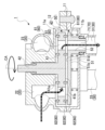
- FIG. 1 is an external perspective view of a flow path switching device (six-way valve) according to a first embodiment
- FIG. 2 is an exploded perspective view of the flow path switching device of the first embodiment (a driving unit is not shown).
- 1 is a cross-sectional view of a flow path switching device according to a first embodiment (a driving unit is not shown).
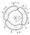
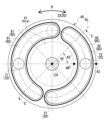
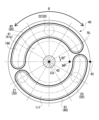
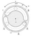
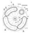
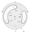
- FIG. 2 is a top view of a rotating disk of the flow path switching device (six-way valve) of the first embodiment.
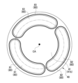
- FIG. 2 is a bottom view of the rotating disk of the flow path switching device (six-way valve) of the first embodiment.
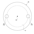
- FIG. 2 is a top view of a fixed disk of the flow path switching device (six-way valve) of the first embodiment.
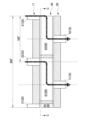
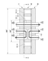
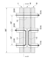
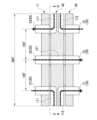
- FIG. 1 shows a first flow path pattern of the flow path switching device (six-way valve) of the first embodiment, and is an expanded view of the axial cross section of the housing, rotating disk, and fixed disk (i.e., a view showing the cross section as viewed from the position shown by the dotted line in FIGS. 4 to 6 toward the radially outward direction of the rotating disk and fixed disk, expanded in a planar circumferential direction).
- 8 is a view taken along the line AA in FIG. 7.
- FIG. 2 is a diagram showing a second flow path pattern of the flow path switching device (six-way valve) of the first embodiment, and is a development view of an axial cross section of the housing, the rotating disk, and the fixed disk.
- 10 is a view taken along the line BB in FIG.
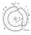
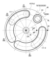
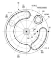
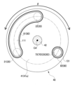
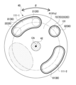
- FIG. 2 is a top view of a rotating disk of the flow path switching device (four-way valve) of the first embodiment.
- FIG. 2 is a bottom view of the rotating disk of the flow path switching device (four-way valve) of the first embodiment.
- FIG. 2 is a top view of a fixed disk of the flow path switching device (four-way valve) of the first embodiment.
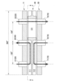
- FIG. 13 is a diagram showing the first flow path pattern of the flow path switching device (four-way valve) of the first embodiment, and is an expanded view of the axial cross section of the housing, rotating disk, and fixed disk (i.e., a diagram showing the cross section as viewed from the position shown by the dotted line in FIGS.
- FIG. 2 is a diagram showing a second flow path pattern of the flow path switching device (four-way valve) of the first embodiment, and is a development view of an axial cross section of the housing, the rotating disk, and the fixed disk. This is a view taken along the line D-D in Figure 16. This is a cross-sectional view taken along the line E-E of Figure 15.
- FIG. 1 is a diagram showing a second flow path pattern of the flow path switching device (four-way valve) of the first embodiment, and is a development view of an axial cross section of the housing, the rotating disk, and the fixed disk. This is a view taken along the line D-D in Figure 16. This is a cross-sectional view taken along the line E-E of Figure 15.
- FIG. 13 is a diagram showing a first flow path pattern of the flow path switching device (six-way valve) of the second embodiment, and is an expanded view of an axial cross section of a housing, a rotating disk, and a fixed disk (i.e., a diagram corresponding to FIG. 7 or FIG. 9 ).
- 20 is a view taken along the line FF in FIG. 19 .
- FIG. 13 is a diagram showing a second flow path pattern of the flow path switching device (six-way valve) of the second embodiment, and is a development view of an axial cross section of the housing, the rotating disk, and the fixed disk. This is a view taken along the line GG in Figure 21.
- FIG. 13 is a diagram showing a first flow path pattern of a flow path switching device (six-way valve) of a third embodiment, and is a development view of an axial cross section of a housing, a rotating disk, and a fixed disk. This is a view taken along the line HH in Figure 23. This is a cross-sectional view taken along line II of Figure 23.
- FIG. 13 is a diagram showing a second flow path pattern of the flow path switching device (six-way valve) of the third embodiment, and is a development view of an axial cross section of the housing, the rotating disk, and the fixed disk. This is a view taken along the line J-J in Figure 26. This is a cross-sectional view taken along the line K-K in FIG. 26.
- FIG. 13 is a development view of an axial cross section of a housing, a rotary disk, and a fixed disk in a flow path switching device (six-way valve) of a fourth embodiment. This is a view taken along the line L-L in Figure 29.
- FIG. 13 is a development view of an axial cross section of a housing, a rotating disk, and a fixed disk in a flow path switching device (six-way valve) according to a first modified example of the fourth embodiment. This is a view taken along the line M-M in Figure 31.
- FIG. 13 is a development view of an axial cross section of a housing, a rotary disk, and a fixed disk in a flow path switching device (six-way valve) according to a second modified example of the fourth embodiment.
- FIG. 13 is a development view of an axial cross section of a housing, a rotary disk, and a fixed disk in a flow path switching device (six-way valve) of a fifth embodiment.
- FIG. This is a view taken along the arrows O-O in Figure 35.
- FIG. 16 is a diagram showing a comparative example with respect to FIG. 15 .
- FIG. 18 is a diagram showing a comparative example with respect to FIG. 17 .
- FIG. 9 is a diagram showing a comparative example with respect to FIG. 8 .
- FIG. 11 is a diagram showing a comparative example with respect to FIG. 10 .
- FIG. 20 is a diagram showing a comparative example with respect to FIG. 19 . This is a view taken along the line QQ in Figure 42.
- FIG. 22 is a diagram showing a comparative example with respect to FIG. 21 . This is a view taken along the line R-R in Figure 44.
- FIG. 24 is a diagram showing a comparative example with respect to FIG. 23 . This is a view taken along the line S-S in Figure 46. This is a cross-sectional view taken along the line T-T of Figure 46. This is a cross-sectional view taken along the line UU in Figure 47.
- FIG. 30 is a diagram showing a comparative example with respect to FIG. 29 . This is a view taken along the line VV in Figure 50.
- FIG. 36 is a diagram showing a comparative example to FIG. 35 . This is a view taken along the line W-W in Figure 52.
- the flow path switching device 1 which is an embodiment of the present disclosure, is described below.
- the flow path switching device 1 of the present embodiment is a multi-way valve such as a four-way valve or a six-way valve.
- the flow path switching device 1 has a housing 11, a valve body portion 12, and a drive portion 13. Note that Figures 1 to 3 show an example in which the flow path switching device 1 is a six-way valve.
- the housing 11 has an inflow flow path 20 through which the fluid flows in, and an outflow flow path 30 through which the fluid flows out.
- the flow path switching device 1 is a six-way valve as an example, so the housing 11 has three inflow flow paths 20 and three outflow flow paths 30.
- the three inflow flow paths 20 include a first inflow flow path 21, a second inflow flow path 22, and a third inflow flow path 23.
- the three outflow flow paths 30 include a first outflow flow path 31, a second outflow flow path 32, and a third outflow flow path 33.
- the housing 11 is formed, for example, from resin.
- the housing 11 is also an example of a "fixed member” in the present disclosure.
- the inflow passage 20 is also an example of a "fixed member connecting passage constituting part of the passage" in the present disclosure.
- the valve body portion 12 is provided inside the housing 11. As shown in Figures 2 and 3, this valve body portion 12 includes a rotating plate-shaped rotating disk 40 and a plate-shaped fixed disk 50.
- the rotating disk 40 and the fixed disk 50 are stacked and arranged in the direction of the central axis CA (hereinafter simply referred to as the "axial direction") of the disk portion 41 of the rotating disk 40 and the disk portion 51 of the fixed disk 50, which will be described later.
- the rotating disk 40 and the fixed disk 50 are formed, for example, from resin.
- the rotating disk 40 is an example of a "rotating member" in this disclosure
- the fixed disk 50 is an example of a "fixed member” in this disclosure.
- the rotating disk 40 has a disk portion 41 and a rotating shaft portion 42.
- the disk portion 41 is formed in a disk shape and includes a rotating disk communication passage 60.
- This rotating disk communication passage 60 penetrates the disk portion 41 in the axial direction and can communicate with the inlet flow passage 20 and the fixed disk communication passage 70 described below.
- the disk portion 41 includes three rotating disk communication passages 60.
- the three rotating disk communication passages 60 include a first rotating disk communication passage 61, a second rotating disk communication passage 62, and a third rotating disk communication passage 63.
- the rotating disk communication passages 60 are an example of a "rotating member communication passage constituting a part of a flow passage" in this disclosure.
- the rotating shaft portion 42 is connected to the disk portion 41 at one end in the direction of its central axis, and is connected to the drive unit 13 at the other end.
- the rotating shaft portion 42 is provided at the center of the disk portion 41 so that its central axis coincides with the central axis CA of the disk portion 41.
- the rotating shaft portion 42 receives rotational power from the drive unit 13 and rotates around its central axis, causing the disk portion 41 connected to the rotating shaft portion 42 to rotate around its central axis CA. In this way, the rotating disk 40 receives rotational power from the drive unit 13 and rotates around the central axis CA.
- the fixed disk 50 has a disk portion 51 and a cylindrical portion 52.
- the disc portion 51 is formed in a disc shape and has a fixed disc communication passage 70 that penetrates in the axial direction.
- the disc portion 51 has three fixed disc communication passages 70.
- the three fixed disc communication passages 70 include a first fixed disc communication passage 71, a second fixed disc communication passage 72, and a third fixed disc communication passage 73.
- the fixed disc communication passage 70 is an example of a "fixed member communication passage that constitutes part of the flow path" in this disclosure.
- the cylindrical portion 52 is connected to the disk portion 51 and is formed to extend in the axial direction from the disk portion 51 so as to surround the fixed disk communication passage 70.
- three cylindrical portions 52 are formed to correspond to the three fixed disk communication passages 70, respectively.
- a seal member 80 is provided as an elastic member between the housing 11 and the rotating disk 40, and between the rotating disk 40 and the fixed disk 50.
- a first seal member 81, a second seal member 82, and a third seal member 83 are provided as three seal members 80.
- the seal member 80 is an example of the "balance member" of the present disclosure.
- the seal member 80 is provided circumferentially on the upper surface 41a and lower surface 41b of the disk portion 41 of the rotating disk 40 so as to surround the periphery of the rotating disk communication passage 60, which is formed in the shape of an elongated hole.
- the seal member 80 contacts the housing 11 and the fixed disk 50 to seal the flow passages (i.e., between the inflow flow passage 20 and the rotating disk communication passage 60 communicating with the inflow flow passage 20, and between the fixed disk communication passage 70 and the rotating disk communication passage 60 communicating with the fixed disk communication passage 70) from the outside.
- the sealing member 80 is formed, for example, from a fluororesin (e.g., Teflon (registered trademark)).
- the sealing member 80 may also be formed from rubber with a fluororesin attached.
- the sealing member 80 may also be formed from a material other than fluororesin or rubber.
- the drive unit 13 is equipped with a motor (not shown) for providing rotational power to the rotating shaft portion 42 of the rotating disk 40.
- the flow path switching device 1 configured as described above forms a flow path through which the fluid flows by combining the inflow flow path 20, the rotating disk communication path 60, and the fixed disk communication path 70 (outflow flow path 30).
- the flow path switching device 1 then switches the combination that connects the inflow flow path 20, the fixed disk communication path 70, and the rotating disk communication path 60 by rotating the rotating disk 40 relative to the housing 11 and the fixed disk 50 using the drive unit 13, thereby switching the flow path pattern through which the fluid flows.
- the first rotating disk communication path 61 connects the second inflow path 22 to the first fixed disk communication path 71.
- the second rotating disk communication path 62 connects the third inflow path 23 to the second fixed disk communication path 72.
- the third rotating disk communication path 63 connects the first inflow path 21 to the third fixed disk communication path 73.
- the first fixed disk communication passage 71 is connected to the first outlet flow passage 31
- the second fixed disk communication passage 72 is connected to the second outlet flow passage 32
- the third fixed disk communication passage 73 is connected to the third outlet flow passage 33.
- the rotating disk 40 can be rotated counterclockwise by the drive unit 13 from the first flow path pattern shown in Figures 7 and 8 to switch to the second flow path pattern shown in Figures 9 and 10.
- counterclockwise means that the rotating disk 40 is in the counterclockwise direction when viewed from the housing 11 side.
- the first rotating disk communication path 61 connects the first inflow flow path 21 to the first fixed disk communication path 71.
- the second rotating disk communication path 62 connects the second inflow flow path 22 to the second fixed disk communication path 72.
- the third rotating disk communication path 63 connects the third inflow flow path 23 to the third fixed disk communication path 73.
- rotating disk 40 can be rotated clockwise by the drive unit 13 from the second flow path pattern state shown in Figures 9 and 10 to switch to the first flow path pattern shown in Figures 7 and 8.
- clockwise means the direction that is clockwise when the rotating disk 40 is viewed from the housing 11 side.
- the disk portion 41 of the rotating disk 40 has two rotating disk communication passages 60, a first rotating disk communication passage 61 and a second rotating disk communication passage 62. Furthermore, as shown in Figure 13, the disk portion 51 of the fixed disk 50 has two fixed disk communication passages 70, a first fixed disk communication passage 71 and a second fixed disk communication passage 72.
- the second inflow flow path 22 and the first fixed disk communication path 71 are connected by a first rotating disk communication path 61.
- the first inflow flow path 21 and the second fixed disk communication path 72 are connected by a second rotating disk communication path 62.
- the rotating disk 40 can be rotated counterclockwise by the drive unit 13 from the first flow path pattern shown in Figures 14 and 15 to switch to the second flow path pattern shown in Figures 16 and 17.
- the first rotating disk communication passage 61 connects the first inflow passage 21 to the first fixed disk communication passage 71 as a second flow path pattern.
- the second rotating disk communication passage 62 connects the second inflow passage 22 to the second fixed disk communication passage 72.
- the rotating disk 40 can be rotated clockwise by the drive unit 13 from the second flow path pattern state shown in Figures 16 and 17 to switch to the first flow path pattern shown in Figures 14 and 15.
- the seal member 80 is not provided in the cross section of the flow path switching device 1 shown in FIG. 38, which is the P-P cross section of FIG. 37.
- the rotating disk 40 becomes prone to tilt. Therefore, when the rotating disk 40 tilts, the surface pressure of the seal member 80 becomes uneven, and there is a risk that the seal member 80 will wear unevenly when the rotating disk 40 rotates. There is also a risk that fluid will easily leak from the seal member 80.
- Figures 37 and 39 show the upper surface 41a of the disk portion 41 of the rotating disk 40, the amount of sliding between the seal member 80 and the fixed disk 50 also increases on the lower surface 41b of the disk portion 41, which accelerates wear of the seal member 80.
- switching rotation angle ⁇ is the rotation angle of the rotating disk 40 when the rotating disk 40 is rotated to switch the flow path pattern, and is, for example, 90° in the examples shown in Figures 37 and 39.
- the rotating disk communication passage 60 i.e., the first rotating disk communication passage 61 and the second rotating disk communication passage 62
- the seal member 80 i.e., the first seal member 81 and the second seal member 82
- the rotating disk communication passage 60 and the seal member 80 are formed so that the switching rotation angle ⁇ of the rotating disk 40 is minimized.
- the rotating disk communication passages 60 and the seal members 80 adjacent in the circumferential direction of the disk portion 41 are formed to be as close as possible to the limit position where the seal members 80 adjacent in the circumferential direction of the disk portion 41 do not come into contact with each other.
- the sealing members 80 are provided on four imaginary radial lines RL that are formed to pass through the central axis CA and are spaced equally (e.g., at 45° intervals) around the circumferential direction of the rotating disk 40, at positions that are symmetrical about the central axis CA.
- the sealing members 80 function to keep the attitude of the rotating disk 40 in balance.
- the radial lines RL are radially formed lines, and are straight lines indicated by dashed lines in FIG. 15.
- the seal member 80 is provided in the cross section of the flow path switching device 1 shown in FIG. 18, which is the E-E cross section of FIG. 15. Therefore, even if an external force such as vibration acts on the rotating disk 40, the seal member 80 can keep the attitude of the rotating disk 40 in balance, making it difficult for the rotating disk 40 to tilt. This makes the surface pressure of the seal member 80 uniform, and makes it possible to suppress uneven wear of the seal member 80 when the rotating disk 40 rotates. In addition, fluid is less likely to leak from the seal member 80.
- the switching rotation angle ⁇ of the rotating disk 40 can be made smaller than in the comparative example shown in Figs. 37 and 39.
- the switching rotation angle ⁇ of the rotating disk 40 can be set to 1/2 to 1/3 of the value in the comparative example shown in Figs. 37 and 39. This reduces the amount of sliding between the seal member 80 and the housing 11 or fixed disk 50, thereby suppressing wear of the seal member 80.
- the seal member 80 is also provided on the radial line RL at a position closer to the outer periphery 43 than the midpoint MP of the line segment connecting the central axis CA and the outer periphery 43 of the rotating disk 40.
- the position of the midpoint MP is indicated by a two-dot chain line.
- a sealing member 80 is used as a member for keeping the attitude of the rotating disk 40 in balance. Therefore, there is no need to add a separate dedicated part for keeping the attitude of the rotating disk 40 in balance other than the sealing member 80. Therefore, the attitude of the rotating disk 40 can be kept in balance while suppressing the number of parts and manufacturing costs.
- the flow path switching device 1 is a six-way valve
- the rotating disk communication passages 60 i.e., the first rotating disk communication passage 61, the second rotating disk communication passage 62, and the third rotating disk communication passage 63
- the seal members 80 i.e., the first seal member 81, the second seal member 82, and the third seal member 83
- the distance between adjacent rotating disk communication passages 60 and seal members 80 in the circumferential direction of the disc portion 41 is larger than in this embodiment shown in FIG. 8.
- Figures 40 and 41 show the upper surface 41a of the disk portion 41 of the rotating disk 40, the amount of sliding between the seal member 80 and the fixed disk 50 also increases on the lower surface 41b of the disk portion 41, which accelerates wear of the seal member 80.
- the rotating disk communication passage 60 i.e., the first rotating disk communication passage 61, the second rotating disk communication passage 62, and the third rotating disk communication passage 63
- the seal member 80 i.e., the first seal member 81, the second seal member 82, and the third seal member 83
- the rotating disk communication passage 60 and the seal member 80 are formed so that the switching rotation angle ⁇ of the rotating disk 40 is minimized.
- the rotating disk communication passages 60 and the seal members 80 adjacent in the circumferential direction of the disk portion 41 are formed to be as close as possible to the limit position where the seal members 80 adjacent in the circumferential direction of the disk portion 41 do not contact each other.
- the seal members 80 are provided at positions symmetrical about the central axis CA on six imaginary radial lines RL that are formed to pass through the central axis CA and are spaced equally (e.g., at 30° intervals) around the circumferential direction of the rotating disk 40.
- the seal members 80 function to keep the attitude of the rotating disk 40 in equilibrium.
- the switching rotation angle ⁇ of the rotating disk 40 can be made smaller than in the comparative example shown in Figures 40 and 41.
- the switching rotation angle ⁇ of the rotating disk 40 can be set to 1/2 to 3/4 of the value in the comparative example shown in Figures 40 and 41.
- the seal member 80 can keep the attitude of the rotating disk 40 in equilibrium, making it difficult for the rotating disk 40 to tilt. This makes the surface pressure of the seal member 80 uniform, and it is possible to suppress uneven wear of the seal member 80 when the rotating disk 40 rotates. In addition, fluid is less likely to leak from the seal member 80.
- the seal member 80 is provided on the radial line RL at a position closer to the outer periphery 43 than the midpoint MP of the line segment connecting the central axis CA and the outer periphery 43 of the rotating disk 40.
- the seal member 80 is used as a member for keeping the attitude of the rotating disk 40 in equilibrium.
- the rotating disk 40 has a housing side communication passage 111, a fixed disk side communication passage 112, and upper and lower straight communication passages 131.
- the housing side communication passage 111 is a passage that connects two inflow passages 20.
- the fixed disk side communication passage 112 is a passage that connects two fixed disk communication passages 70.
- the upper and lower straight communication passages 131 are passages that connect one inflow passage 20 and one fixed disk communication passage 70.
- Figure 20 shows the upper surface 41a of the disk portion 41 of the rotating disk 40
- the lower surface 41b of the disk portion 41 also has the fixed disk side communication passage 112 and the upper and lower straight communication passages 131 formed therein, similar to the housing side communication passage 111 and the upper and lower straight communication passages 131 shown in Figure 20.
- housing side communication passage 111 the fixed disk side communication passage 112, and the upper and lower straight communication passages 131 are each an example of a "rotating member communication passage" in this disclosure.
- the rotating disk 40 can be rotated counterclockwise by the driving unit 13 to switch to the second flow path pattern shown in Figures 21 and 22. Also, from the state of the second flow path pattern shown in Figures 21 and 22, the rotating disk 40 can be rotated clockwise by the driving unit 13 to switch to the first flow path pattern shown in Figures 19 and 20.
- the housing side communication passage 111 and the upper and lower straight communication passages 131 are formed on the upper surface 41a of the disc portion 41 of the rotating disc 40 as shown in Figures 42 and 43.
- the distance between the housing side communication passage 111 and the first seal member 81 and the upper and lower straight communication passages 131 and the second seal member 82 i.e., the distance in the circumferential direction of the disc portion 41
- the area in the circumferential direction of the disk portion 41 where the seal member 80 is not provided is large. Therefore, when an external force such as vibration acts on the rotating disk 40, the rotating disk 40 is likely to tilt. Therefore, when the rotating disk 40 tilts, the surface pressure of the seal member 80 becomes uneven, and there is a risk that the seal member 80 will wear unevenly when the rotating disk 40 rotates. There is also a risk that fluid will easily leak from the seal member 80.
- the housing side communication passage 111 and the first seal member 81, and the upper and lower straight communication passages 131 and the second seal member 82 are formed to be extended in the circumferential direction of the rotating disk 40 compared to the comparative example. This narrows the distance between the housing side communication passage 111 and the first seal member 81 and the upper and lower straight communication passages 131 and the second seal member 82 as much as possible.
- the housing side communication passage 111 and the upper and lower straight communication passages 131 are formed so that the switching rotation angle ⁇ of the rotating disk 40 is minimized.
- the housing side communication passage 111 (and the first seal member 81) and the upper and lower straight communication passages 131 (and the second seal member 82) adjacent in the circumferential direction of the disc portion 41 are formed to be closest to each other to the limit position where the seal members 80 adjacent in the circumferential direction of the disc portion 41 do not contact each other.
- the distance between the fixed disk side communication passage 112 and the first seal member 81 and the upper and lower straight communication passages 131 and the second seal member 82 is also narrowed as much as possible.
- the seal members 80 are provided on six imaginary radial lines RL that pass through the central axis CA and are arranged at equal intervals (e.g., 30° intervals) around the circumferential direction of the rotating disk 40, at positions that are symmetrical about the central axis CA.
- the seal member 80 is provided around almost the entire circumference of the rotating disk 40. Therefore, when an external force such as vibration acts on the rotating disk 40, the seal member 80 can keep the attitude of the rotating disk 40 in balance, making it difficult for the rotating disk 40 to tilt. Therefore, the surface pressure of the seal member 80 becomes uniform, making it difficult for the seal member 80 to wear unevenly when the rotating disk 40 rotates. In addition, fluid is less likely to leak from the seal member 80.
- the switching rotation angle ⁇ of the rotating disk 40 can be made smaller than in the comparative examples shown in Figures 42 and 44.
- the third embodiment will be described with respect to the points different from the first and second embodiments, and a description of the points common to the first and second embodiments will be omitted.
- the disk portion 41 of the rotating disk 40 has a housing side communication passage 111, a fixed disk side communication passage 112, and a rotating disk communication passage 160.
- the rotating disk communication passage 160 is an example of the "rotating member communication passage" of this disclosure.
- the rotating disk 40 can be rotated counterclockwise by the driving unit 13 to switch to the second flow path pattern shown in Figures 26 to 28. Also, from the second flow path pattern state shown in Figures 26 to 28, the rotating disk 40 can be rotated clockwise by the driving unit 13 to switch to the first flow path pattern shown in Figures 23 to 25.
- the housing side communication passage 111, the fixed disk side communication passage 112, and the rotating disk communication passage 160 are formed on the upper surface 41a and the lower surface 41b of the disc portion 41 of the rotating disk 40 as shown in Figures 47 and 48.
- the distance between the housing side communication passage 111 and the first seal member 81 and the rotating disk communication passage 160 and the second seal member 82 is larger than in this embodiment shown in Figure 24.
- the distance between the fixed disk side communication passage 112 and the first seal member 81 and the rotating disk communication passage 160 and the second seal member 82 is larger than in this embodiment shown in Figure 25.
- the switching rotation angle ⁇ of the rotating disk 40 becomes large. This increases the amount of sliding between the seal member 80 and the housing 11 or the fixed disk 50, accelerating wear of the seal member 80.
- the housing side communication passage 111 and the first seal member 81, and the rotating disk communication passage 160 and the second seal member 82 are formed to extend in the circumferential direction of the rotating disk 40 compared to the comparative example. This makes it possible to narrow the distance as much as possible between the housing side communication passage 111 and the first seal member 81 and the rotating disk communication passage 160 and the second seal member 82.
- the distance between the fixed disk side communication passage 112 and the first seal member 81 and the rotating disk side communication passage 160 and the second seal member 82 is narrowed as much as possible.
- the seal members 80 are provided at positions symmetrical about the central axis CA on six imaginary radial lines RL that are formed to pass through the central axis CA and are spaced equally (e.g., at 30° intervals) around the circumferential direction of the rotating disk 40.
- the seal member 80 is provided around almost the entire circumference of the rotating disk 40. Therefore, when an external force such as vibration acts on the rotating disk 40, the rotating disk 40 is less likely to tilt. Therefore, the surface pressure of the seal member 80 becomes uniform, and the seal member 80 is less likely to wear unevenly when the rotating disk 40 rotates. In addition, fluid is less likely to leak from the seal member 80.
- the switching rotation angle ⁇ of the rotating disk 40 can be made smaller than in the comparative example.
- the fourth embodiment will be described with respect to the points different from the first to third embodiments, and a description of the points in common with the first to third embodiments will be omitted.
- the disk portion 41 of the rotating disk 40 has a first housing side communication passage 111-1, a second housing side communication passage 111-2, a first fixed disk side communication passage 112-1, a second fixed disk side communication passage 112-2, and upper and lower straight communication passages 131.
- Figure 30 shows the upper surface 41a of the disk portion 41 of the rotating disk 40
- the lower surface 41b of the disk portion 41 also has the first fixed disk side communicating passage 112-1, the second fixed disk side communicating passage 112-2, and the upper and lower straight communicating passages 131 formed therein, similar to the first housing side communicating passage 111-1, the second housing side communicating passage 111-2, and the upper and lower straight communicating passages 131 shown in Figure 30.
- first housing side communication passage 111-1, the second housing side communication passage 111-2, the first fixed disk side communication passage 112-1, and the second fixed disk side communication passage 112-2 are each an example of a "rotating member communication passage" in this disclosure.
- the first seal member 81 is formed on the upper surface 41a of the disk portion 41 of the rotating disk 40 as shown in FIG. 51.
- the seal member 80 is not provided in the hatched area surrounded by the dashed-dotted ellipse in FIG. 51.
- the rotating disk 40 is likely to tilt. Therefore, when the rotating disk 40 tilts, the surface pressure of the seal member 80 (i.e., the first seal member 81 and the second seal member 82) becomes uneven, and there is a risk that the seal member 80 will wear unevenly when the rotating disk 40 rotates. There is also a risk that fluid will easily leak from the seal member 80.
- the first seal member 81 is extended in the circumferential direction of the rotating disk 40 compared to the comparative example. This narrows the gap as much as possible between the first seal member 81 provided around the first housing side communication passage 111-1 and the first seal member 81 provided around the second housing side communication passage 111-2.
- the seal members 80 i.e., the first seal member 81 or the second seal member 82
- the seal members 80 are provided at positions symmetrical about the central axis CA on six imaginary radial lines RL that are formed to pass through the central axis CA and are spaced equally (e.g., at 30° intervals) circumferentially around the rotating disk 40.
- the seal member 80 is provided around almost the entire circumference of the rotating disk 40. Therefore, when an external force such as vibration acts on the rotating disk 40, the rotating disk 40 is less likely to tilt. Therefore, the surface pressure of the seal member 80 becomes uniform, and the seal member 80 is less likely to wear unevenly when the rotating disk 40 rotates. In addition, fluid is less likely to leak from the seal member 80.
- the first seal member 81 provided around the first housing side communication passage 111-1 on the upper surface 41a of the disc portion 41 of the rotating disc 40 may be extended in the circumferential direction of the rotating disc 40 compared to the comparative example.
- the first seal member 81 provided around the first fixed disc side communication passage 112-1 on the lower surface 41b of the disc portion 41 of the rotating disc 40 is extended in the circumferential direction of the rotating disc 40 compared to the comparative example.
- a dummy elastic member 84 may be provided on the upper surface 41a of the disc portion 41 of the rotating disc 40 between the first seal member 81 provided around the first housing side communication passage 111-1 and the first seal member 81 provided around the second housing side communication passage 111-2.
- a dummy elastic member 84 is provided on the lower surface 41b of the disc portion 41 of the rotating disc 40 between the first seal member 81 provided around the first fixed disc side communication passage 112-1 and the first seal member 81 provided around the second fixed disc side communication passage 112-2.
- the fifth embodiment will be described with respect to the points different from the first to fourth embodiments, and a description of the points in common with the first to fourth embodiments will be omitted.
- the disk portion 41 of the rotating disk 40 has a housing side communication passage 111, a fixed disk side communication passage 112, and four upper and lower straight communication passages 131 (i.e., a first upper and lower straight communication passage 131-1, a second upper and lower straight communication passage 131-2, a third upper and lower straight communication passage 131-3, and a fourth upper and lower straight communication passage 131-4).
- Figure 36 shows the upper surface 41a of the disk portion 41 of the rotating disk 40
- the lower surface 41b of the disk portion 41 also has the fixed disk side communication passage 112 and the upper and lower straight communication passages 131 formed therein, similar to the housing side communication passage 111 and the upper and lower straight communication passages 131 shown in Figure 36.
- first vertical straight communication passage 131-1, the second vertical straight communication passage 131-2, the third vertical straight communication passage 131-3, and the fourth vertical straight communication passage 131-4 are each an example of a "rotating member communication passage" in this disclosure.
- the seal member 80 is not provided in the hatched area surrounded by the dashed-dotted ellipse in FIG. 53. This makes the rotating disk 40 prone to tilt when an external force such as vibration acts on the rotating disk 40. As a result, tilting of the rotating disk 40 causes the surface pressure of the seal member 80 to become uneven, and there is a risk that the seal member 80 will wear unevenly when the rotating disk 40 rotates. There is also a risk that fluid will easily leak from the seal member 80.
- a dummy elastic member 84 is provided between the third vertical straight communication passage 131-3 and the fourth vertical straight communication passage 131-4.
- the sealing members 80 are provided at positions symmetrical about the central axis CA on four imaginary radial lines RL that are formed to pass through the central axis CA and are spaced equally (e.g., at 45° intervals) circumferentially around the rotating disk 40.
- the seal members 80 are provided at approximately equal positions around the circumference of the rotating disk 40. Therefore, when an external force such as vibration acts on the rotating disk 40, the rotating disk 40 is less likely to tilt. Therefore, the surface pressure of the seal members 80 is uniform, and the seal members 80 are less likely to wear unevenly when the rotating disk 40 rotates. In addition, fluid is less likely to leak from the seal members 80.
- Flow path switching device 11 Housing 12 Valve body portion 20 Inflow flow path 21 First inflow flow path 22 Second inflow flow path 23 Third inflow flow path 30 Outflow flow path 31 First outflow flow path 32 Second outflow flow path 33 Third outflow flow path 40 Rotating disk 41 Disk portion 43 Outer periphery portion 50 Fixed disk 51 Disk portion 60 Rotating disk communication passage 61 First rotating disk communication passage 62 Second rotating disk communication passage 63 Third rotating disk communication passage 70 Fixed disk communication passage 71 First fixed disk communication passage 72 Second fixed disk communication passage 73 Third fixed disk communication passage 80 Seal member 81 First seal member 82 Second seal member 83 Third seal member 111 Housing side communication passage 111-1 First housing side communication passage 111-2 Second housing side communication passage 112 Fixed disk side communication passage 112-1 First fixed disk side communication passage 112-2 Second fixed disk side communication passage 131 Upper and lower straight communication passage 131-1 First upper and lower straight communication passage 131-2 Second upper and lower straight communication passage 131-3 Third upper and lower straight communication passage 131-4 Fourth upper and lower straight communication passage 160 Rotating disk communication passage CA Central axis RL Radi
Landscapes
- Engineering & Computer Science (AREA)
- General Engineering & Computer Science (AREA)
- Mechanical Engineering (AREA)
- Multiple-Way Valves (AREA)
Abstract
固定部材と、前記固定部材に対して相対的に回転する円板状の回転部材と、を有し、前記固定部材は、流路の一部を構成する固定部材連通路を備え、前記回転部材は、前記流路の一部を構成する回転部材連通路を備え、前記固定部材に対して前記回転部材を相対的に回転させて、前記固定部材連通路と前記回転部材連通路を連通させる組み合わせを切り替えることにより、前記流路のパターンを切り替える流路切替装置において、前記固定部材と前記回転部材の間に設けられ、前記流路を外部から封止するシール部材と、前記固定部材と前記回転部材の間に設けられ、前記回転部材の姿勢を平衡に保つ平衡保持部材と、を有し、前記平衡保持部材は、前記回転部材をその中心軸方向から見たときに、前記中心軸を通り前記回転部材の周方向に等間隔に配置されるように形成される少なくとも4本の仮想の放射状の線の上にて、前記中心軸を中心にして対称となる位置に設けられている。
Description
本開示は、流路のパターンを切り替える流路切替装置に関する。
特許文献1には、複数の連通路を備える主弁体を回転させて、連通路により連通させるポートの組み合わせを切り換えることにより、流路のパターンを切り換える流路切換弁が開示されている。
特許文献1の流路切換弁においては、主弁体(回転部材)を弁シート側に付勢する圧縮コイルばねが設けられているが、振動等の外力により主弁体が振れて主弁体の姿勢を平衡に保てないと、弁シートのシート面に接する主弁体の凸部(シール部材)が偏摩耗するおそれがある。
そこで、本開示は上記した課題を解決するためになされたものであり、回転部材の姿勢を平衡に保ち、シール部材が偏摩耗することを抑制できる流路切替装置を提供することを目的とする。
上記課題を解決するためになされた本開示の一形態は、固定部材と、前記固定部材に対して相対的に回転する円板状の回転部材と、を有し、前記固定部材は、流路の一部を構成する固定部材連通路を備え、前記回転部材は、前記流路の一部を構成する回転部材連通路を備え、前記固定部材に対して前記回転部材を相対的に回転させて、前記固定部材連通路と前記回転部材連通路を連通させる組み合わせを切り替えることにより、前記流路のパターンを切り替える流路切替装置において、前記固定部材と前記回転部材の間に設けられ、前記流路を外部から封止するシール部材と、前記固定部材と前記回転部材の間に設けられ、前記回転部材の姿勢を平衡に保つ平衡保持部材と、を有し、前記平衡保持部材は、前記回転部材をその中心軸方向から見たときに、前記中心軸を通り前記回転部材の周方向に等間隔に配置されるように形成される少なくとも4本の仮想の放射状の線の上にて、前記中心軸を中心にして対称となる位置に設けられていること、を特徴とする。
この態様によれば、回転部材に振動等の外力が作用しても、平衡保持部材により回転部材の姿勢を平衡に保つことができる。そのため、シール部材が偏摩耗することを抑制できる。
上記の態様においては、前記平衡保持部材は、前記放射状の線の上にて、前記中心軸と前記回転部材の外周部とを結ぶ線分の中点の位置よりも、前記外周部側の位置に設けられていること、が好ましい。
この態様によれば、より効果的に、平衡保持部材により回転部材の姿勢を平衡に保つことができる。そのため、シール部材のロバスト性、すなわち、振動等の外力に対する強靭性が向上する。
上記の態様においては、前記平衡保持部材は、前記シール部材であること、が好ましい。
この態様によれば、平衡保持部材として、シール部材を使用する。そのため、シール部材以外に、回転部材の姿勢を平衡に保つための専用の部品を別途追加する必要がない。したがって、部品点数や製造コストを抑えながら、回転部材の姿勢を平衡に保つことができる。
上記の態様においては、前記シール部材と前記回転部材連通路は、前記流路のパターンを切り替えるときの前記回転部材の回転角度が最小となるように形成されること、が好ましい。
この態様によれば、シール部材と固定部材の摺動量を少なくできるので、シール部材が摩耗することを抑制できる。
本開示の流路切替装置によれば、回転部材の姿勢を平衡に保ち、シール部材が偏摩耗することを抑制できる。
本開示の実施形態である流路切替装置1について説明する。
<第1実施形態>
(流路切替装置の概要説明)
まず、本実施形態の流路切替装置1の概要について説明する。本実施形態の流路切替装置1は、四方弁や六方弁などの多方弁である。
(流路切替装置の概要説明)
まず、本実施形態の流路切替装置1の概要について説明する。本実施形態の流路切替装置1は、四方弁や六方弁などの多方弁である。
図1~図3に示すように、流路切替装置1は、ハウジング11と、弁体部12と、駆動部13を有する。なお、図1~図3では、流路切替装置1を六方弁とした例を示している。
ハウジング11は、流体が流入する流入流路20と、流体が流出する流出流路30と、を備えている。ここでは、流路切替装置1は、一例として六方弁としているので、ハウジング11は、3つの流入流路20と3つの流出流路30とを備えている。そして、3つの流入流路20として、第1流入流路21と第2流入流路22と第3流入流路23とが設けられている。また、3つの流出流路30として、第1流出流路31と第2流出流路32と第3流出流路33とが設けられている。
なお、ハウジング11は、例えば樹脂により形成されている。また、ハウジング11は本開示の「固定部材」の一例である。また、流入流路20は、本開示の「流路の一部を構成する固定部材連通路」の一例である。
弁体部12は、ハウジング11の内部に設けられている。この弁体部12は、図2と図3に示すように、回転する板状の回転ディスク40と、板状の固定ディスク50と、を備えている。そして、回転ディスク40と固定ディスク50は、後述する回転ディスク40の円板部41や固定ディスク50の円板部51の中心軸CA方向(以下、単に「軸方向」という。)に積層して配置されている。
なお、回転ディスク40と固定ディスク50は、例えば樹脂により形成されている。また、回転ディスク40は本開示の「回転部材」の一例であり、固定ディスク50は本開示の「固定部材」の一例である。
図2~図5に示すように、回転ディスク40は、円板部41と回転軸部42を備えている。
円板部41は、円板状に形成されており、回転ディスク連通路60を備えている。この回転ディスク連通路60は、円板部41を軸方向に貫通し、流入流路20や後述する固定ディスク連通路70と連通可能である。ここでは、円板部41は、3つの回転ディスク連通路60を備えている。そして、図2や図4や図5に示すように、3つの回転ディスク連通路60として、第1回転ディスク連通路61と第2回転ディスク連通路62と第3回転ディスク連通路63を備えている。なお、回転ディスク連通路60は、本開示の「流路の一部を構成する回転部材連通路」の一例である。
回転軸部42は、その中心軸方向について、一端側にて円板部41と接続しており、他端側にて駆動部13に接続している。この回転軸部42は、その中心軸が円板部41の中心軸CAと一致するようにして、円板部41の中央の位置に設けられている。そして、駆動部13から回転する動力を得て回転軸部42がその中心軸を中心に回転することにより、回転軸部42に接続する円板部41がその中心軸CAを中心に回転する。このようにして、回転ディスク40は、駆動部13から回転する動力を得ることにより、中心軸CAを中心に回転する。
図2と図3と図6に示すように、固定ディスク50は、円板部51と円筒部52とを備えている。
円板部51は、円板状に形成されており、軸方向に貫通する固定ディスク連通路70を備えている。ここでは、円板部51は、3つの固定ディスク連通路70を備えている。そして、図2や図6に示すように、3つの固定ディスク連通路70として、第1固定ディスク連通路71と第2固定ディスク連通路72と第3固定ディスク連通路73を備えている。なお、固定ディスク連通路70は、本開示の「流路の一部を構成する固定部材連通路」の一例である。
円筒部52は、円板部51に接続しており、固定ディスク連通路70を囲うようにして円板部51から軸方向に延びるようにして形成されている。ここでは、円筒部52は、3つの固定ディスク連通路70のそれぞれに対応するようにして、3つ形成されている。
また、図3に示すように、ハウジング11と回転ディスク40との間、および、回転ディスク40と固定ディスク50との間には、それぞれ、弾性部材としてシール部材80が設けられている。ここでは、図4などに示すように、3つのシール部材80として、第1シール部材81と第2シール部材82と第3シール部材83が設けられている。なお、シール部材80は、本開示の「平衡保持部材」の一例である。
シール部材80は、図2~図5などに示すように、回転ディスク40における円板部41の上面41aと下面41bにて、長孔状に形成される回転ディスク連通路60の周囲を囲むようにして周状に設けられている。そして、シール部材80は、ハウジング11や固定ディスク50に接触して、流路(すなわち、流入流路20と当該流入流路20に連通する回転ディスク連通路60との間や、固定ディスク連通路70と当該固定ディスク連通路70に連通する回転ディスク連通路60との間)を、外部から封止(シール)する。
なお、シール部材80は、例えばフッ素樹脂(例えば、テフロン(登録商標))により形成されている。また、シール部材80は、フッ素樹脂を貼付したゴムにより形成されていてもよい。さらに、シール部材80は、フッ素樹脂やゴム以外の材料により形成されていてもよい。
駆動部13は、回転ディスク40の回転軸部42に回転する動力を与えるためのモータ(不図示)を備えている。
以上のような構成の流路切替装置1は、流入流路20と回転ディスク連通路60と固定ディスク連通路70(流出流路30)とを組み合わせることで、流体が流れる流路を形成する。そして、流路切替装置1は、駆動部13により回転ディスク40をハウジング11や固定ディスク50に対して相対的に回転させて、流入流路20や固定ディスク連通路70と回転ディスク連通路60とを連通させる組み合わせを切り替えることにより、流体が流れる流路パターンを切り替える。
例えば、図7と図8に示すように、第1の流路パターンとして、第1回転ディスク連通路61により、第2流入流路22と第1固定ディスク連通路71とを連通させる。また、第2回転ディスク連通路62により、第3流入流路23と第2固定ディスク連通路72とを連通させる。さらに、第3回転ディスク連通路63により、第1流入流路21と第3固定ディスク連通路73とを連通させる。
なお、第1固定ディスク連通路71は第1流出流路31に接続し、第2固定ディスク連通路72は第2流出流路32に接続し、第3固定ディスク連通路73は第3流出流路33に接続している。
そして、図7と図8に示す第1の流路パターンの状態から、駆動部13により回転ディスク40を反時計回りに回転させて、図9と図10に示す第2の流路パターンに切り替えることができる。なお、「反時計回り」とは、回転ディスク40をハウジング11側から見たときに反時計回りとなる方向である、という意味である。
これにより、図9と図10に示すように、第2の流路パターンとして、第1回転ディスク連通路61により、第1流入流路21と第1固定ディスク連通路71とを連通させる。また、第2回転ディスク連通路62により、第2流入流路22と第2固定ディスク連通路72とを連通させる。さらに、第3回転ディスク連通路63により、第3流入流路23と第3固定ディスク連通路73とを連通させる。
また、図9と図10に示す第2の流路パターンの状態から、駆動部13により回転ディスク40を時計回りに回転させて、図7と図8に示す第1の流路パターンに切り替えることができる。なお、「時計回り」とは、回転ディスク40をハウジング11側から見たときに時計回りとなる方向である、という意味である。
また、流路切替装置1が四方弁のときには、図11と図12に示すように、回転ディスク40の円板部41は、2つの回転ディスク連通路60として、第1回転ディスク連通路61と第2回転ディスク連通路62を備えている。さらに、図13に示すように、固定ディスク50の円板部51は、2つの固定ディスク連通路70として、第1固定ディスク連通路71と第2固定ディスク連通路72を備えている。
そして、例えば、図14と図15に示すように、第1の流路パターンとして、第1回転ディスク連通路61により、第2流入流路22と第1固定ディスク連通路71とを連通させる。また、第2回転ディスク連通路62により、第1流入流路21と第2固定ディスク連通路72とを連通させる。
そして、図14と図15に示す第1の流路パターンの状態から、駆動部13により回転ディスク40を反時計回りに回転させて、図16と図17に示す第2の流路パターンに切り替えることができる。
これにより、図16と図17に示すように、第2の流路パターンとして、第1回転ディスク連通路61により、第1流入流路21と第1固定ディスク連通路71とを連通させる。また、第2回転ディスク連通路62により、第2流入流路22と第2固定ディスク連通路72とを連通させる。
そして、図16と図17に示す第2の流路パターンの状態から、駆動部13により回転ディスク40を時計回りに回転させて、図14と図15に示す第1の流路パターンに切り替えることができる。
(回転ディスク連通路とシール部材について)
ここで、例えば、流路切替装置1が四方弁のときに、比較例として、回転ディスク40の円板部41において、回転ディスク連通路60(すなわち、第1回転ディスク連通路61と第2回転ディスク連通路62)とシール部材80(すなわち、第1シール部材81と第2シール部材82)が、図37に示すように形成されている場合を想定する。この比較例では、円板部41の周方向に隣り合う回転ディスク連通路60およびシール部材80同士の間隔が、図15に示す本実施形態よりも、大きく形成されている。
ここで、例えば、流路切替装置1が四方弁のときに、比較例として、回転ディスク40の円板部41において、回転ディスク連通路60(すなわち、第1回転ディスク連通路61と第2回転ディスク連通路62)とシール部材80(すなわち、第1シール部材81と第2シール部材82)が、図37に示すように形成されている場合を想定する。この比較例では、円板部41の周方向に隣り合う回転ディスク連通路60およびシール部材80同士の間隔が、図15に示す本実施形態よりも、大きく形成されている。
すると、この比較例では、図37のP-P断面図である図38に示す流路切替装置1の断面にて、シール部材80が設けられていない。そのため、回転ディスク40に振動などの外力が作用したときに、回転ディスク40が傾き易くなってしまう。したがって、回転ディスク40が傾くことにより、シール部材80の面圧が不均一になり、回転ディスク40が回転するときにシール部材80が偏摩耗するおそれがある。また、シール部材80から流体が漏れ易くなるおそれもある。
また、回転ディスク40を回転させて流路パターンを図37と図39に示すように切り替える場合に、回転ディスク40の切替え回転角度θが大きくなってしまう。そのため、シール部材80とハウジング11との摺動量が多くなるので、シール部材80の摩耗が促進されてしまう。
また、図37と図39は回転ディスク40の円板部41の上面41aを示しているが、円板部41の下面41bにおいても同様に、シール部材80と固定ディスク50との摺動量が多くなるので、シール部材80の摩耗が促進されてしまう。
なお、「切替え回転角度θ」は、回転ディスク40を回転させて流路パターンを切り替えるときの回転ディスク40の回転角度であり、図37と図39に示す例では例えば90°となる。
これに対し、本実施形態では、図15に示すように、比較例と比べて、回転ディスク連通路60(すなわち、第1回転ディスク連通路61と第2回転ディスク連通路62)とシール部材80(すなわち、第1シール部材81と第2シール部材82)を、回転ディスク40の周方向に延長させて形成している。そして、これにより、円板部41の周方向に隣り合う回転ディスク連通路60およびシール部材80同士の間隔を、可能な限り狭めている。具体的には、回転ディスク連通路60とシール部材80は、回転ディスク40の切替え回転角度θが最小となるように形成されている。より詳しくは、円板部41の周方向に隣り合うシール部材80同士が接しない限界の位置まで、円板部41の周方向に隣り合う回転ディスク連通路60およびシール部材80を最接近させるように形成されている。
このようにして、本実施形態では、図15に示すように、回転ディスク40をその中心軸CA方向から見たときに、中心軸CAを通り回転ディスク40の周方向に等間隔(例えば、45°間隔)に配置されるように形成される4本の仮想の放射状の線RLの上にて、中心軸CAを中心にして対称となる位置にシール部材80が設けられている。そして、このシール部材80が、回転ディスク40の姿勢を平衡に保つように機能している。なお、放射状の線RLは、放射状に形成される線であって、図15にて一点鎖線で示す直線である。
これにより、図15のE-E断面図である図18に示す流路切替装置1の断面にて、シール部材80が設けられている。そのため、回転ディスク40に振動などの外力が作用しても、シール部材80により回転ディスク40の姿勢を平衡に保つことができるので、回転ディスク40が傾き難くなる。したがって、シール部材80の面圧が均一になり、回転ディスク40が回転するときにシール部材80が偏摩耗することを抑制できる。また、シール部材80から流体が漏れ難くなる。
また、本実施形態では、図15と図17に示すように、図37と図39に示す比較例と比べて、回転ディスク40の切替え回転角度θを小さくすることができる。具体的には、例えば、回転ディスク40の切替え回転角度θを、図37と図39に示す比較例の値の1/2~1/3の値にすることができる。これにより、シール部材80とハウジング11や固定ディスク50との摺動量を少なくできるので、シール部材80が摩耗することを抑制できる。
また、シール部材80は、放射状の線RLの上にて、中心軸CAと回転ディスク40の外周部43とを結ぶ線分の中点MPの位置よりも、外周部43側の位置に設けられている。なお、図15では、中点MPの位置を2点鎖線で示している。
これにより、より効果的に、シール部材80により回転ディスク40の姿勢を平衡に保つことができる。そのため、シール部材80のロバスト性、すなわち、振動等の外力に対する強靭性が向上する。
また、回転ディスク40の姿勢を平衡に保つ部材として、シール部材80を使用している。そのため、シール部材80以外に、回転ディスク40の姿勢を平衡に保つための専用の部品を別途追加する必要がない。したがって、部品点数や製造コストを抑えながら、回転ディスク40の姿勢を平衡に保つことができる。
また、例えば、流路切替装置1が六方弁のときに、比較例として、回転ディスク40の円板部41の上面41aにおいて、回転ディスク連通路60(すなわち、第1回転ディスク連通路61と第2回転ディスク連通路62と第3回転ディスク連通路63)と、シール部材80(すなわち、第1シール部材81と第2シール部材82と第3シール部材83)とが、図40に示すように形成されている場合を想定する。そして、この比較例では、円板部41の周方向に隣り合う回転ディスク連通路60およびシール部材80同士の間隔が、図8に示す本実施形態よりも、大きく形成されている。
すると、この比較例では、回転ディスク40を回転させて流路パターンを図40と図41に切り替える場合に、回転ディスク40の切替え回転角度θが大きくなってしまう。そのため、シール部材80とハウジング11の摺動量が多くなるので、シール部材80の摩耗が促進されてしまう。
また、図40と図41は回転ディスク40の円板部41の上面41aを示しているが、円板部41の下面41bにおいても同様に、シール部材80と固定ディスク50との摺動量が多くなるので、シール部材80の摩耗が促進されてしまう。
これに対し、本実施形態では、図8に示すように、比較例と比べて、回転ディスク連通路60(すなわち、第1回転ディスク連通路61と第2回転ディスク連通路62と第3回転ディスク連通路63)およびシール部材80(すなわち、第1シール部材81と第2シール部材82と第3シール部材83)を回転ディスク40の周方向に延長させて形成している。そして、これにより、円板部41の周方向に隣り合う回転ディスク連通路60およびシール部材80同士の間隔を、可能な限り狭めている。具体的には、図8と図10に示すように、回転ディスク連通路60とシール部材80は、回転ディスク40の切替え回転角度θが最小となるように形成されている。より詳しくは、円板部41の周方向に隣り合うシール部材80同士が接しない限界の位置まで、円板部41の周方向に隣り合う回転ディスク連通路60およびシール部材80を最接近させるように形成されている。
このようにして、本実施形態では、図8に示すように、回転ディスク40をその中心軸CA方向から見たときに、中心軸CAを通り回転ディスク40の周方向に等間隔(例えば、30°間隔)に配置されるように形成される6本の仮想の放射状の線RLの上にて、中心軸CAを中心にして対称となる位置にシール部材80が設けられている。そして、このシール部材80が、回転ディスク40の姿勢を平衡に保つように機能している。
このようにして、本実施形態では、図40と図41に示す比較例と比べて、回転ディスク40の切替え回転角度θを小さくすることができる。例えば、回転ディスク40の切替え回転角度θを、図40と図41に示す比較例の値の1/2~3/4の値にすることができる。
また、回転ディスク40に振動などの外力が作用しても、シール部材80により回転ディスク40の姿勢を平衡に保つことができるので、回転ディスク40が傾き難くなる。そのため、シール部材80の面圧が均一になり、回転ディスク40が回転するときにシール部材80が偏摩耗することを抑制できる。また、シール部材80から流体が漏れ難くなる。
また、シール部材80は、放射状の線RLの上にて、中心軸CAと回転ディスク40の外周部43とを結ぶ線分の中点MPの位置よりも、外周部43側の位置に設けられている。また、回転ディスク40の姿勢を平衡に保つ部材として、シール部材80を使用している。
<第2実施形態>
次に、第2実施形態について、第1実施形態と異なる点を説明し、第1実施形態と共通する点の説明は省略する。
次に、第2実施形態について、第1実施形態と異なる点を説明し、第1実施形態と共通する点の説明は省略する。
本実施形態では、図19と図20に示すように、回転ディスク40は、ハウジング側連通路111と、固定ディスク側連通路112と、上下ストレート連通路131を備えている。ハウジング側連通路111は、2つの流入流路20を連通させる通路である。固定ディスク側連通路112は、2つの固定ディスク連通路70を連通させる通路である。上下ストレート連通路131は、1つの流入流路20と1つの固定ディスク連通路70を連通させる通路である。
なお、図20は回転ディスク40の円板部41の上面41aを示しているが、円板部41の下面41bにおいても、図20に示すハウジング側連通路111と上下ストレート連通路131と同様に、固定ディスク側連通路112と上下ストレート連通路131が形成されている。
なお、ハウジング側連通路111と固定ディスク側連通路112と上下ストレート連通路131は、それぞれ、本開示の「回転部材連通路」の一例である。
そして、図19と図20に示す第1の流路パターンの状態から、駆動部13により回転ディスク40を反時計回りに回転させて、図21と図22に示す第2の流路パターンに切り替えることができる。また、図21と図22に示す第2の流路パターンの状態から、駆動部13により回転ディスク40を時計回りに回転させて、図19と図20に示す第1の流路パターンに切り替えることができる。
ここで、比較例として、回転ディスク40の円板部41の上面41aにおいて、ハウジング側連通路111と上下ストレート連通路131が、図42と図43に示すように形成されている場合を想定する。この比較例では、ハウジング側連通路111および第1シール部材81と、上下ストレート連通路131および第2シール部材82との間隔(すなわち、円板部41の周方向の間隔)が、図19と図20に示す本実施形態よりも、大きく形成されている。
すると、この比較例では、円板部41の周方向において、シール部材80が設けられていない領域が大きい。そのため、回転ディスク40に振動などの外力が作用したときに、回転ディスク40が傾き易くなってしまう。したがって、回転ディスク40が傾くことにより、シール部材80の面圧が不均一になり、回転ディスク40が回転するときにシール部材80が偏摩耗するおそれがある。また、シール部材80から流体が漏れ易くなるおそれもある。
また、回転ディスク40を回転させて流路パターンを図43と図45に示すように切り替える場合に、回転ディスク40の切替え回転角度θが大きくなってしまう。そのため、シール部材80とハウジング11との摺動量が多くなるので、シール部材80の摩耗が促進されてしまう。なお、図43と図45は回転ディスク40の円板部41の上面41aを示しているが、円板部41の下面41bにおいても同様に、シール部材80と固定ディスク50との摺動量が多くなるので、シール部材80の摩耗が促進されてしまう。
これに対し、本実施形態では、図20に示すように、比較例と比べて、ハウジング側連通路111および第1シール部材81と、上下ストレート連通路131および第2シール部材82を、回転ディスク40の周方向に延長させて形成している。そして、これにより、ハウジング側連通路111および第1シール部材81と、上下ストレート連通路131および第2シール部材82との間隔を、可能な限り狭めている。具体的には、図20と図22に示すように、ハウジング側連通路111と上下ストレート連通路131は、回転ディスク40の切替え回転角度θが最小となるように形成されている。より詳しくは、円板部41の周方向に隣り合うシール部材80同士が接しない限界の位置まで、円板部41の周方向に隣り合うハウジング側連通路111(および第1シール部材81)と上下ストレート連通路131(および第2シール部材82)とを最接近させるように形成されている。なお、不図示であるが、固定ディスク側連通路112および第1シール部材81と、上下ストレート連通路131および第2シール部材82との間隔も、同様にして、可能な限り狭めている。
このようにして、本実施形態では、図20に示すように、回転ディスク40をその中心軸CA方向から見たときに、中心軸CAを通り回転ディスク40の周方向に等間隔(例えば、30°間隔)に配置されるように形成される6本の仮想の放射状の線RLの上にて、中心軸CAを中心にして対称となる位置にシール部材80が設けられている。
これにより、回転ディスク40の周方向の略全周に亘って、シール部材80が設けられている。そのため、回転ディスク40に振動などの外力が作用したときに、シール部材80により回転ディスク40の姿勢を平衡に保つことができるので、回転ディスク40が傾き難くなる。したがって、シール部材80の面圧が均一になり、回転ディスク40が回転するときにシール部材80が偏摩耗し難くなる。また、シール部材80から流体が漏れ難くなる。
また、図20と図22に示すように、図42と図44に示す比較例と比べて、回転ディスク40の切替え回転角度θを小さくすることができる。
<第3実施形態>
次に、第3実施形態について、第1,2実施形態と異なる点を説明し、第1,2実施形態と共通する点の説明は省略する。
次に、第3実施形態について、第1,2実施形態と異なる点を説明し、第1,2実施形態と共通する点の説明は省略する。
本実施形態では、図23~図28に示すように、回転ディスク40の円板部41は、ハウジング側連通路111と、固定ディスク側連通路112と、回転ディスク連通路160を備えている。なお、回転ディスク連通路160は、本開示の「回転部材連通路」の一例である。
そして、図23~図25に示す第1の流路パターンの状態から、駆動部13により回転ディスク40を反時計回りに回転させて、図26~図28に示す第2の流路パターンに切り替えることができる。また、図26~図28に示す第2の流路パターンの状態から、駆動部13により回転ディスク40を時計回りに回転させて、図23~図25に示す第1の流路パターンに切り替えることができる。
ここで、比較例として、回転ディスク40の円板部41の上面41aと下面41bにおいて、ハウジング側連通路111と、固定ディスク側連通路112と、回転ディスク連通路160が図47と図48に示すように形成されている場合を想定する。この比較例では、ハウジング側連通路111および第1シール部材81と、回転ディスク連通路160および第2シール部材82との間隔が、図24に示す本実施形態よりも、大きく形成されている。また、固定ディスク側連通路112および第1シール部材81と、回転ディスク連通路160および第2シール部材82との間隔が、図25に示す本実施形態よりも、大きく形成されている。
すると、この比較例では、図47のU-U断面図である図49に示す流路切替装置1の断面にて、シール部材80が設けられていない領域αが存在する。そのため、回転ディスク40に振動などの外力が作用したときに、回転ディスク40が傾き易くなってしまう。したがって、回転ディスク40が傾くことにより、シール部材80の面圧が不均一になり、回転ディスク40が回転するときにシール部材80が偏摩耗するおそれがある。また、シール部材80から流体が漏れ易くなるおそれもある。
また、回転ディスク40の切替え回転角度θが大きくなってしまう。そのため、シール部材80とハウジング11または固定ディスク50との摺動量が多くなるので、シール部材80の摩耗が促進されてしまう。
これに対し、本実施形態では、図24に示すように、比較例と比べて、ハウジング側連通路111および第1シール部材81と、回転ディスク連通路160および第2シール部材82を、回転ディスク40の周方向に延長させて形成している。そして、これにより、ハウジング側連通路111および第1シール部材81と、回転ディスク連通路160および第2シール部材82との間隔を、出来るだけ狭めている。
また、図25に示すように、比較例と比べて、同様に、固定ディスク側連通路112および第1シール部材81と、回転ディスク連通路160および第2シール部材82との間隔を、出来るだけ狭めている。
このようにして、本実施形態では、図24と図25に示すように、回転ディスク40をその中心軸CA方向から見たときに、中心軸CAを通り回転ディスク40の周方向に等間隔(例えば、30°間隔)に配置されるように形成される6本の仮想の放射状の線RLの上にて、中心軸CAを中心にして対称となる位置にシール部材80が設けられている。
これにより、回転ディスク40の周方向の略全周に亘って、シール部材80が設けられている。そのため、回転ディスク40に振動などの外力が作用したときに、回転ディスク40が傾き難くなる。したがって、シール部材80の面圧が均一になり、回転ディスク40が回転するときにシール部材80が偏摩耗し難くなる。また、シール部材80から流体が漏れ難くなる。
また、比較例と比べて、回転ディスク40の切替え回転角度θを小さくすることができる。
<第4実施形態>
次に、第4実施形態について、第1~3実施形態と異なる点を説明し、第1~3実施形態と共通する点の説明は省略する。
次に、第4実施形態について、第1~3実施形態と異なる点を説明し、第1~3実施形態と共通する点の説明は省略する。
本実施形態では、図29と図30に示すように、回転ディスク40の円板部41は、第1ハウジング側連通路111-1と、第2ハウジング側連通路111-2と、第1固定ディスク側連通路112-1と、第2固定ディスク側連通路112-2と、上下ストレート連通路131を備えている。
なお、図30は回転ディスク40の円板部41の上面41aを示しているが、円板部41の下面41bにおいても、図30に示す第1ハウジング側連通路111-1と第2ハウジング側連通路111-2と上下ストレート連通路131と同様に、第1固定ディスク側連通路112-1と第2固定ディスク側連通路112-2と上下ストレート連通路131が形成されている。
なお、第1ハウジング側連通路111-1と第2ハウジング側連通路111-2と第1固定ディスク側連通路112-1と第2固定ディスク側連通路112-2は、それぞれ、本開示の「回転部材連通路」の一例である。
ここで、比較例として、回転ディスク40の円板部41の上面41aにおいて第1シール部材81が図51に示すように形成されている場合を想定する。
すると、この比較例では、図51にて一点鎖線の楕円で囲んだハッチングされた領域において、シール部材80が設けられていない。そのため、回転ディスク40に振動などの外力が作用したときに、回転ディスク40が傾き易くなってしまう。したがって、回転ディスク40が傾くことにより、シール部材80(すなわち、第1シール部材81と第2シール部材82)の面圧が不均一になり、回転ディスク40が回転するときにシール部材80が偏摩耗するおそれがある。また、シール部材80から流体が漏れ易くなるおそれもある。
これに対し、本実施形態では、図30に示すように、比較例と比べて、第1シール部材81を、回転ディスク40の周方向に延長させて形成している。そして、これにより、第1ハウジング側連通路111-1の周囲に設けられる第1シール部材81と、第2ハウジング側連通路111-2の周囲に設けられる第1シール部材81との間隔を、出来るだけ狭めている。
このようにして、本実施形態では、図30に示すように、回転ディスク40をその中心軸CA方向から見たときに、中心軸CAを通り回転ディスク40の周方向に等間隔(例えば、30°間隔)に配置されるように形成される6本の仮想の放射状の線RLの上にて、中心軸CAを中心にして対称となる位置にシール部材80(すなわち、第1シール部材81または第2シール部材82)が設けられている。
そして、これにより、回転ディスク40の周方向の略全周に亘って、シール部材80が設けられている。そのため、回転ディスク40に振動などの外力が作用したときに、回転ディスク40が傾き難くなる。したがって、シール部材80の面圧が均一になり、回転ディスク40が回転するときにシール部材80が偏摩耗し難くなる。また、シール部材80から流体が漏れ難くなる。
また、第1の変形例として、図32に示すように、回転ディスク40の円板部41の上面41aにおいて、比較例と比べて、第1ハウジング側連通路111-1の周囲に設けられる第1シール部材81を、回転ディスク40の周方向に延長させて形成してもよい。また、このとき、同様に、不図示であるが、回転ディスク40の円板部41の下面41bにおいて、比較例と比べて、第1固定ディスク側連通路112-1の周囲に設けられる第1シール部材81を、回転ディスク40の周方向に延長させて形成しておく。
さらに、第2の変形例として、図34に示すように、回転ディスク40の円板部41の上面41aにおいて、第1ハウジング側連通路111-1の周囲に設けられる第1シール部材81と、第2ハウジング側連通路111-2の周囲に設けられる第1シール部材81との間に、ダミーの弾性部材84を設けてもよい。このとき、同様に、不図示であるが、回転ディスク40の円板部41の下面41bにおいて、第1固定ディスク側連通路112-1の周囲に設けられる第1シール部材81と、第2固定ディスク側連通路112-2の周囲に設けられる第1シール部材81との間に、ダミーの弾性部材84を設けておく。
<第5実施形態>
次に、第5実施形態について、第1~4実施形態と異なる点を説明し、第1~4実施形態と共通する点の説明は省略する。
次に、第5実施形態について、第1~4実施形態と異なる点を説明し、第1~4実施形態と共通する点の説明は省略する。
本実施形態では、図35と図36に示すように、回転ディスク40の円板部41は、ハウジング側連通路111と、固定ディスク側連通路112と、4つの上下ストレート連通路131(すなわち、第1上下ストレート連通路131-1と、第2上下ストレート連通路131-2と、第3上下ストレート連通路131-3と、第4上下ストレート連通路131-4)を備えている。
なお、図36は回転ディスク40の円板部41の上面41aを示しているが、円板部41の下面41bにおいても、図36に示すハウジング側連通路111と上下ストレート連通路131と同様に、固定ディスク側連通路112と上下ストレート連通路131が形成されている。
なお、第1上下ストレート連通路131-1と第2上下ストレート連通路131-2と第3上下ストレート連通路131-3と第4上下ストレート連通路131-4は、それぞれ、本開示の「回転部材連通路」の一例である。
ここで、比較例として、回転ディスク40の円板部41の上面41aにおいて、ハウジング側連通路111と4つの上下ストレート連通路131が図53に示すように形成されている場合を想定する。
すると、この比較例では、図53にて一点鎖線の楕円で囲んだハッチングされた領域において、シール部材80が設けられていない。そのため、回転ディスク40に振動などの外力が作用したときに、回転ディスク40が傾き易くなってしまう。したがって、回転ディスク40が傾くことにより、シール部材80の面圧が不均一になり、回転ディスク40が回転するときにシール部材80が偏摩耗するおそれがある。また、シール部材80から流体が漏れ易くなるおそれもある。
これに対し、本実施形態では、図36に示すように、第3上下ストレート連通路131-3と第4上下ストレート連通路131-4の間に、ダミーの弾性部材84が設けられている。
このようにして、本実施形態では、図36に示すように、回転ディスク40をその中心軸CA方向から見たときに、中心軸CAを通り回転ディスク40の周方向に等間隔(例えば、45°間隔)に配置されるように形成される4本の仮想の放射状の線RL上にて、中心軸CAを中心にして対称となる位置にシール部材80が設けられている。
これにより、回転ディスク40の周方向について略均等な位置に、シール部材80が設けられている。そのため、回転ディスク40に振動などの外力が作用したときに、回転ディスク40が傾き難くなる。したがって、シール部材80の面圧が均一になり、回転ディスク40が回転するときにシール部材80が偏摩耗し難くなる。また、シール部材80から流体が漏れ難くなる。
なお、上記した実施の形態は単なる例示にすぎず、本開示を何ら限定するものではなく、その要旨を逸脱しない範囲内で種々の改良、変形が可能であることはもちろんである。
1 流路切替装置
11 ハウジング
12 弁体部
20 流入流路
21 第1流入流路
22 第2流入流路
23 第3流入流路
30 流出流路
31 第1流出流路
32 第2流出流路
33 第3流出流路
40 回転ディスク
41 円板部
43 外周部
50 固定ディスク
51 円板部
60 回転ディスク連通路
61 第1回転ディスク連通路
62 第2回転ディスク連通路
63 第3回転ディスク連通路
70 固定ディスク連通路
71 第1固定ディスク連通路
72 第2固定ディスク連通路
73 第3固定ディスク連通路
80 シール部材
81 第1シール部材
82 第2シール部材
83 第3シール部材
111 ハウジング側連通路
111-1 第1ハウジング側連通路
111-2 第2ハウジング側連通路
112 固定ディスク側連通路
112-1 第1固定ディスク側連通路
112-2 第2固定ディスク側連通路
131 上下ストレート連通路
131-1 第1上下ストレート連通路
131-2 第2上下ストレート連通路
131-3 第3上下ストレート連通路
131-4 第4上下ストレート連通路
160 回転ディスク連通路
CA 中心軸
RL 放射状の線
θ 切替え回転角度
11 ハウジング
12 弁体部
20 流入流路
21 第1流入流路
22 第2流入流路
23 第3流入流路
30 流出流路
31 第1流出流路
32 第2流出流路
33 第3流出流路
40 回転ディスク
41 円板部
43 外周部
50 固定ディスク
51 円板部
60 回転ディスク連通路
61 第1回転ディスク連通路
62 第2回転ディスク連通路
63 第3回転ディスク連通路
70 固定ディスク連通路
71 第1固定ディスク連通路
72 第2固定ディスク連通路
73 第3固定ディスク連通路
80 シール部材
81 第1シール部材
82 第2シール部材
83 第3シール部材
111 ハウジング側連通路
111-1 第1ハウジング側連通路
111-2 第2ハウジング側連通路
112 固定ディスク側連通路
112-1 第1固定ディスク側連通路
112-2 第2固定ディスク側連通路
131 上下ストレート連通路
131-1 第1上下ストレート連通路
131-2 第2上下ストレート連通路
131-3 第3上下ストレート連通路
131-4 第4上下ストレート連通路
160 回転ディスク連通路
CA 中心軸
RL 放射状の線
θ 切替え回転角度
Claims (4)
- 固定部材と、
前記固定部材に対して相対的に回転する円板状の回転部材と、を有し、
前記固定部材は、流路の一部を構成する固定部材連通路を備え、
前記回転部材は、前記流路の一部を構成する回転部材連通路を備え、
前記固定部材に対して前記回転部材を相対的に回転させて、前記固定部材連通路と前記回転部材連通路を連通させる組み合わせを切り替えることにより、前記流路のパターンを切り替える流路切替装置において、
前記固定部材と前記回転部材の間に設けられ、前記流路を外部から封止するシール部材と、
前記固定部材と前記回転部材の間に設けられ、前記回転部材の姿勢を平衡に保つ平衡保持部材と、を有し、
前記平衡保持部材は、前記回転部材をその中心軸方向から見たときに、前記中心軸を通り前記回転部材の周方向に等間隔に配置されるように形成される少なくとも4本の仮想の放射状の線の上にて、前記中心軸を中心にして対称となる位置に設けられていること、
を特徴とする流路切替装置。 - 請求項1の流路切替装置において、
前記平衡保持部材は、前記放射状の線の上にて、前記中心軸と前記回転部材の外周部とを結ぶ線分の中点の位置よりも、前記外周部側の位置に設けられていること、
を特徴とする流路切替装置。 - 請求項1または2の流路切替装置において、
前記平衡保持部材は、前記シール部材であること、
を特徴とする流路切替装置。 - 請求項3の流路切替装置において、
前記シール部材と前記回転部材連通路は、前記流路のパターンを切り替えるときの前記回転部材の回転角度が最小となるように形成されること、
を特徴とする流路切替装置。
Applications Claiming Priority (2)
| Application Number | Priority Date | Filing Date | Title |
|---|---|---|---|
| JP2023078417A JP2024162675A (ja) | 2023-05-11 | 2023-05-11 | 流路切替装置 |
| JP2023-078417 | 2023-05-11 |
Publications (1)
| Publication Number | Publication Date |
|---|---|
| WO2024232140A1 true WO2024232140A1 (ja) | 2024-11-14 |
Family
ID=93430143
Family Applications (1)
| Application Number | Title | Priority Date | Filing Date |
|---|---|---|---|
| PCT/JP2024/006286 Ceased WO2024232140A1 (ja) | 2023-05-11 | 2024-02-21 | 流路切替装置 |
Country Status (2)
| Country | Link |
|---|---|
| JP (1) | JP2024162675A (ja) |
| WO (1) | WO2024232140A1 (ja) |
Citations (2)
| Publication number | Priority date | Publication date | Assignee | Title |
|---|---|---|---|---|
| JPH08303600A (ja) * | 1995-05-10 | 1996-11-19 | Toto Ltd | ロータリバルブ用リップパッキン |
| US20060042686A1 (en) * | 2004-08-25 | 2006-03-02 | Controle Analytique Inc. | Rotary valve and analytical chromatographic system using the same |
-
2023
- 2023-05-11 JP JP2023078417A patent/JP2024162675A/ja active Pending
-
2024
- 2024-02-21 WO PCT/JP2024/006286 patent/WO2024232140A1/ja not_active Ceased
Patent Citations (2)
| Publication number | Priority date | Publication date | Assignee | Title |
|---|---|---|---|---|
| JPH08303600A (ja) * | 1995-05-10 | 1996-11-19 | Toto Ltd | ロータリバルブ用リップパッキン |
| US20060042686A1 (en) * | 2004-08-25 | 2006-03-02 | Controle Analytique Inc. | Rotary valve and analytical chromatographic system using the same |
Also Published As
| Publication number | Publication date |
|---|---|
| JP2024162675A (ja) | 2024-11-21 |
Similar Documents
| Publication | Publication Date | Title |
|---|---|---|
| JP7685625B2 (ja) | ロータリーディスクバルブ | |
| CN113227620B (zh) | 多端口多平面阀 | |
| JP2024525305A (ja) | ロータリーディスクバルブ | |
| US11939981B2 (en) | Rotary disc valve | |
| JP2024527686A (ja) | ロータリーディスクバルブ | |
| CN116292976A (zh) | 旋转盘阀 | |
| TW202108924A (zh) | 旋轉接頭 | |
| JP2020051547A (ja) | バルブ装置 | |
| KR20160124652A (ko) | 유체 전환 밸브 및 유체 전환 밸브를 구비하는 기기 및 냉장고 | |
| JP2024162675A (ja) | 流路切替装置 | |
| JP7287245B2 (ja) | 制御弁 | |
| CN120390857A (zh) | 旋转阀的密封件 | |
| WO2024048798A1 (ja) | 流路切替装置 | |
| KR102728283B1 (ko) | 실링 부재 및 이를 포함하는 밸브 어셈블리 | |
| JP7548596B2 (ja) | ロータリバルブ | |
| JP7807353B2 (ja) | 流路切替装置 | |
| JP7235328B2 (ja) | バルブ | |
| JP2024115173A (ja) | 流路切替装置 | |
| WO2024135384A1 (ja) | ロータリバルブ | |
| JP7424688B1 (ja) | ロータリバルブ | |
| JP7248300B2 (ja) | ロータリバルブ | |
| WO2025009334A1 (ja) | 流路切替装置 | |
| CN120813793A (zh) | 流路切换装置 | |
| WO2026048577A1 (ja) | 切換弁 | |
| JP2024124299A (ja) | 流路切替装置 |
Legal Events
| Date | Code | Title | Description |
|---|---|---|---|
| 121 | Ep: the epo has been informed by wipo that ep was designated in this application |
Ref document number: 24803255 Country of ref document: EP Kind code of ref document: A1 |
|
| NENP | Non-entry into the national phase |
Ref country code: DE |