WO2024232099A1 - 計算装置 - Google Patents
計算装置 Download PDFInfo
- Publication number
- WO2024232099A1 WO2024232099A1 PCT/JP2023/017812 JP2023017812W WO2024232099A1 WO 2024232099 A1 WO2024232099 A1 WO 2024232099A1 JP 2023017812 W JP2023017812 W JP 2023017812W WO 2024232099 A1 WO2024232099 A1 WO 2024232099A1
- Authority
- WO
- WIPO (PCT)
- Prior art keywords
- criterion
- machining
- machining condition
- unit
- condition
- Prior art date
- Legal status (The legal status is an assumption and is not a legal conclusion. Google has not performed a legal analysis and makes no representation as to the accuracy of the status listed.)
- Ceased
Links
Images



Classifications
-
- G—PHYSICS
- G05—CONTROLLING; REGULATING
- G05B—CONTROL OR REGULATING SYSTEMS IN GENERAL; FUNCTIONAL ELEMENTS OF SUCH SYSTEMS; MONITORING OR TESTING ARRANGEMENTS FOR SUCH SYSTEMS OR ELEMENTS
- G05B19/00—Program-control systems
- G05B19/02—Program-control systems electric
- G05B19/18—Numerical control [NC], i.e. automatically operating machines, in particular machine tools, e.g. in a manufacturing environment, so as to execute positioning, movement or co-ordinated operations by means of program data in numerical form
- G05B19/406—Numerical control [NC], i.e. automatically operating machines, in particular machine tools, e.g. in a manufacturing environment, so as to execute positioning, movement or co-ordinated operations by means of program data in numerical form characterised by monitoring or safety
-
- B—PERFORMING OPERATIONS; TRANSPORTING
- B23—MACHINE TOOLS; METAL-WORKING NOT OTHERWISE PROVIDED FOR
- B23Q—DETAILS, COMPONENTS, OR ACCESSORIES FOR MACHINE TOOLS, e.g. ARRANGEMENTS FOR COPYING OR CONTROLLING; MACHINE TOOLS IN GENERAL CHARACTERISED BY THE CONSTRUCTION OF PARTICULAR DETAILS OR COMPONENTS; COMBINATIONS OR ASSOCIATIONS OF METAL-WORKING MACHINES, NOT DIRECTED TO A PARTICULAR RESULT
- B23Q15/00—Automatic control or regulation of feed movement, cutting velocity or position of tool or work
- B23Q15/007—Automatic control or regulation of feed movement, cutting velocity or position of tool or work while the tool acts upon the workpiece
- B23Q15/12—Adaptive control, i.e. adjusting itself to have a performance which is optimum according to a preassigned criterion
-
- B—PERFORMING OPERATIONS; TRANSPORTING
- B23—MACHINE TOOLS; METAL-WORKING NOT OTHERWISE PROVIDED FOR
- B23C—MILLING
- B23C3/00—Milling particular work; Special milling operations; Machines therefor
-
- G—PHYSICS
- G05—CONTROLLING; REGULATING
- G05B—CONTROL OR REGULATING SYSTEMS IN GENERAL; FUNCTIONAL ELEMENTS OF SUCH SYSTEMS; MONITORING OR TESTING ARRANGEMENTS FOR SUCH SYSTEMS OR ELEMENTS
- G05B19/00—Program-control systems
- G05B19/02—Program-control systems electric
- G05B19/18—Numerical control [NC], i.e. automatically operating machines, in particular machine tools, e.g. in a manufacturing environment, so as to execute positioning, movement or co-ordinated operations by means of program data in numerical form
- G05B19/182—Numerical control [NC], i.e. automatically operating machines, in particular machine tools, e.g. in a manufacturing environment, so as to execute positioning, movement or co-ordinated operations by means of program data in numerical form characterised by the machine tool function, e.g. thread cutting, cam making, tool direction control
-
- G—PHYSICS
- G05—CONTROLLING; REGULATING
- G05B—CONTROL OR REGULATING SYSTEMS IN GENERAL; FUNCTIONAL ELEMENTS OF SUCH SYSTEMS; MONITORING OR TESTING ARRANGEMENTS FOR SUCH SYSTEMS OR ELEMENTS
- G05B19/00—Program-control systems
- G05B19/02—Program-control systems electric
- G05B19/18—Numerical control [NC], i.e. automatically operating machines, in particular machine tools, e.g. in a manufacturing environment, so as to execute positioning, movement or co-ordinated operations by means of program data in numerical form
- G05B19/416—Numerical control [NC], i.e. automatically operating machines, in particular machine tools, e.g. in a manufacturing environment, so as to execute positioning, movement or co-ordinated operations by means of program data in numerical form characterised by control of velocity, acceleration or deceleration
- G05B19/4163—Adaptive control of feed or cutting velocity
-
- G—PHYSICS
- G05—CONTROLLING; REGULATING
- G05B—CONTROL OR REGULATING SYSTEMS IN GENERAL; FUNCTIONAL ELEMENTS OF SUCH SYSTEMS; MONITORING OR TESTING ARRANGEMENTS FOR SUCH SYSTEMS OR ELEMENTS
- G05B2219/00—Program-control systems
- G05B2219/30—Nc systems
- G05B2219/37—Measurements
- G05B2219/37434—Measuring vibration of machine or workpiece or tool
-
- G—PHYSICS
- G05—CONTROLLING; REGULATING
- G05B—CONTROL OR REGULATING SYSTEMS IN GENERAL; FUNCTIONAL ELEMENTS OF SUCH SYSTEMS; MONITORING OR TESTING ARRANGEMENTS FOR SUCH SYSTEMS OR ELEMENTS
- G05B2219/00—Program-control systems
- G05B2219/30—Nc systems
- G05B2219/49—Nc machine tool, till multiple
- G05B2219/49277—Oscillating, swinging feed drive, for grinding
-
- G—PHYSICS
- G05—CONTROLLING; REGULATING
- G05B—CONTROL OR REGULATING SYSTEMS IN GENERAL; FUNCTIONAL ELEMENTS OF SUCH SYSTEMS; MONITORING OR TESTING ARRANGEMENTS FOR SUCH SYSTEMS OR ELEMENTS
- G05B2219/00—Program-control systems
- G05B2219/30—Nc systems
- G05B2219/49—Nc machine tool, till multiple
- G05B2219/49314—Machine with oscillating workpiece, no full rotation
Definitions
- This disclosure relates to a computing device.
- Patent Documents 1 and 2 there is known a technique for performing oscillating machining in machine tools, in which a tool is oscillated relative to a workpiece to shred chips (see, for example, Patent Documents 1 and 2).
- Patent No. 6843313 International Publication No. 2021/167014
- the machining conditions for oscillating cutting include the spindle speed, feed rate, frequency multiplier, which is the number of oscillations per one rotation of the spindle, and oscillation amplitude multiplier, which is the amplitude ratio to the feed amount per one rotation of the spindle.
- the machining conditions must satisfy the operable conditions, such as the oscillation operation being within the upper limit of the oscillation acceleration, and the chip shredding.
- This disclosure has been made in consideration of the above problems, and aims to provide a technology that makes it easy to determine whether the numerical values of machining conditions satisfy the expected operating conditions in a machine tool that performs oscillating machining.
- the present disclosure relates to a calculation device for a machine tool that performs swing machining while swinging a cutting tool and a workpiece relative to one another, the calculation device including a machining condition acquisition unit that acquires at least one of a spindle speed, a feed rate, a frequency parameter, and an amplitude parameter included in the machining conditions as a first machining condition, a judgment unit that acquires as judgment criteria a first criterion that is set for a swing operation based on the first machining condition and at least one second machining condition that is not acquired as the first machining condition among the machining conditions, and a second criterion that is set for a swing operation determined only by the second machining condition, and an output unit that outputs a judgment result of the judgment unit, and the judgment unit is a calculation device that judges whether or not there is a numerical value of the second machining condition that satisfies the first criterion and the second criterion when the numerical value of the first machining condition is applied.
- FIG. 2 is a functional block diagram of a calculation device of the machine tool according to the first embodiment.
- 5 is a flowchart illustrating an example of a process flow of calculation control by the computing device of the first embodiment.
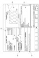
- FIG. 13 is a diagram showing an example of an image displayed on a display unit by a computing device.
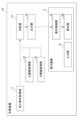
- FIG. 13 is a functional block diagram of a calculation device of a machine tool according to a fifth embodiment.
- FIG. 13 is a functional block diagram of a calculation device of a machine tool according to a sixth embodiment.
- [First embodiment] 1 is a functional block diagram of a calculation device 1 of a machine tool according to the first embodiment.
- the calculation device 1 according to the first embodiment is a computer that calculates various information of a machine tool that performs swing machining while swinging a cutting tool and a workpiece relative to one another.
- the calculation device 1 assists in setting machining conditions for swing cutting.
- the calculation device 1 is used, for example, by being connected to a control device (not shown) that is a computer that controls the machine tool.
- a machine tool processes a workpiece with a cutting tool by operating at least one spindle that rotates the cutting tool and the workpiece relative to one another, and at least one feed axis that moves the cutting tool relative to the workpiece.
- the machine tool performs various types of machining based on a machining program.
- the shape of the workpiece is not limited when machining with the machine tool according to this embodiment. In other words, it can be applied even when the workpiece has a tapered or arc-shaped portion on the machining surface, requiring multiple feed axes (Z-axis and X-axis), or when the workpiece is cylindrical or cylindrical and only one specific feed axis (Z-axis) is sufficient.
- the calculation device 1 is configured using a computer equipped with memories such as ROM (read only memory) and RAM (random access memory), a CPU (control processing unit), and a communication control unit, which are connected to each other via a bus, for example.
- memories such as ROM (read only memory) and RAM (random access memory), a CPU (control processing unit), and a communication control unit, which are connected to each other via a bus, for example.
- the computing device 1 of this embodiment also includes a display device 2 that displays various information.
- the display device 2 includes a display unit 20 and an input unit 21.
- the display unit 20 is, for example, configured by a display that displays various information.
- the input unit 21 is, for example, an operating means such as a touch panel, keyboard, or buttons through which an operator inputs various information.
- the calculation device 1 of the machine tool may be configured as a CNC (Computer Numerical Controller) and may be connected to a higher-level computer (not shown) such as a CNC or a PLC (Programmable Logic Controller).
- a higher-level computer such as a CNC or a PLC (Programmable Logic Controller).
- machining conditions such as rotation speed may be input to the calculation device 1 of the machine tool from the higher-level computer. It may also be an external computer for simulating oscillating cutting that is not connected to the machine tool.
- the calculation device 1 has a processing condition acquisition unit 11, an upper limit value acquisition unit 12, a judgment unit 13, and an output unit 14 as functional units. These functional units of the calculation device 1 are realized by the cooperation of the CPU, memory, and the control program stored in the memory.
- the machining condition acquisition unit 11 is a machining condition acquisition function that acquires the machining conditions for performing oscillation machining.
- the machining conditions are explained below.
- the machining conditions include information necessary for machining, such as the spindle rotation speed S (1/min), the feed amount per spindle rotation F (mm/rev), the command position of the feed axis, and the oscillation conditions.
- the feed amount per spindle rotation (mm/rev) can also be calculated from a combination of the spindle rotation speed (1/min) and the feed rate (mm/min) of the cutting tool.
- the oscillation conditions included in the machining conditions include at least a frequency parameter, which is information about the oscillation frequency of the cutting tool or workpiece, and an amplitude parameter, which is information about the oscillation amplitude of the cutting tool or workpiece, as information for uniquely identifying the vibration waveform.
- the frequency parameter may be the relative number of vibrations per rotation of the cutting tool and workpiece, or the number of vibrations per unit time. It may also be a periodic parameter of the forward and backward movement.
- the amplitude parameter may be information about the oscillation amplitude relative to the relative feed amount per rotation of the cutting tool and workpiece, or a distance parameter of the forward and backward movement.
- These periodic parameters of the forward and backward movement and distance parameters of the forward and backward movement may be determined from the forward speed, backward speed, forward distance, backward distance, spindle rotation speed, control period, etc.
- the frequency parameter and amplitude parameter may be determined from the spindle rotation speed, feed rate per minute, frequency magnification, which is the relative number of vibrations per rotation of the cutting tool and workpiece, and amplitude magnification, which is the oscillation amplitude relative to the relative feed amount per rotation of the cutting tool and workpiece.
- the oscillation frequency f (Hz) per rotation of the spindle and the oscillation frequency magnification I (times) are used as frequency parameters.
- the oscillation frequency magnification I (times) may be specified directly, or may be calculated from the oscillation frequency (Hz) and the rotation speed S (1/min) of the spindle after specifying the oscillation frequency (Hz).
- the oscillation amplitude A (mm) relative to the magnitude of the feed amount per revolution of the spindle and the oscillation amplitude magnification K (times) indicating the magnitude of the oscillation amplitude are used.
- the oscillation amplitude magnification K (times) may also be directly specified in the same way.
- the feed rate per minute can also be set as a processing condition.
- frequency parameters, and amplitude parameters instead of the feed rate, frequency parameters, and amplitude parameters, the forward amount, forward speed, retraction amount, retraction speed, control cycle, number of teeth, etc. can also be set as processing conditions.
- the machining condition acquisition unit 11 selects the first machining condition and the second machining condition from among the machining conditions.
- the first machining condition is a machining condition for which a numerical value has already been set.
- the first machining condition may be one arbitrarily designated by the operator from among the machining conditions for which a numerical value has already been set, or the first machining condition may be determined based on a rule previously determined in the calculation device.
- the numerical value of the first machining condition may be, for example, one designated by the operator to the calculation device 1 through the input unit 21 or an external computer according to the display of the display unit 20 of the calculation device 1, or one previously designated in the machining program or the setting parameters of the machine tool.
- the second machining condition is a machining condition that has not yet been determined, and is a machining condition for which a numerical value needs to be determined.
- the first machining condition and the second machining condition may each be one condition or multiple conditions.
- the numerical value of the second machining condition may already be determined, but even if a value has been input, the input value is ignored, and the present technology is applied based on a combination of setting values of the second machining condition that meets the second criterion again.
- the upper limit acquisition unit 12 is an upper limit acquisition function that acquires the upper limit of the oscillation status (parameter).
- the upper limit of the swing status is L A and the lower limit is L B.
- Examples of the swing status include a frequency upper limit (L A > S ⁇ I), an amplitude upper limit and a lower limit (L A >F ⁇ K> L B ), a swing maximum speed upper limit (L A > F ⁇ S+(F ⁇ K) ⁇ (2 ⁇ S ⁇ I)/2), a swing maximum acceleration upper limit (L A > (F ⁇ K) ⁇ (2 ⁇ S ⁇ I) 2 /2), a swing maximum jerk upper limit (L A > (F ⁇ K) ⁇ (2 ⁇ S ⁇ I) 3 /2), etc.
- a return speed upper limit, etc. can also be used. In this way, the upper and lower limits of the swing status can be set to various parameters related to the swing conditions.
- the determination unit 13 is a determination function that determines whether or not a combination of values of the second processing conditions exists based on a first criterion and a second criterion that are set in advance, assuming the values of the first processing conditions.
- the first criterion is a condition that is set for an operation that changes based on the first processing condition and the second processing condition.
- the first criterion is a condition that is set in advance for an operation that is based on the first processing condition and the second processing condition.
- the first criterion is set to be that the oscillation acceleration (oscillation parameter) of the oscillation operation based on the first processing condition and the second processing condition falls below the upper limit value acquired by the upper limit value acquisition unit 12. If the maximum acceleration is the upper limit value Amax , the first criterion can be expressed as in Equation (1).
- the second criterion is a condition that is set for an operation whose results change depending only on the second processing condition.
- the second criterion is set to be the ability to shred the chips.
- the second criterion can be expressed as in formula (2). From formula (2), it can be seen that the only conditions that determine whether or not the chips can be shredded are the oscillation frequency magnification I and oscillation amplitude magnification K, which are set as the second processing condition.
- the above formula (1) is written as the condition for an oscillating motion that allows chip shredding. This is the condition for the tool path paths of the nth rotation and the n+1th rotation to overlap and cause an air cut. However, in reality, even if an air cut does not occur, chip shredding may be possible if the cutting path distance is sufficiently short. Therefore, the condition for an oscillating motion that allows chip shredding may be determined by providing an additional margin to the above formula (1), or the machining conditions I and K and the table data of the actual machining results on whether or not chip shredding was actually possible at that time may be referenced to determine whether the conditions allow chip shredding.
- the determination unit 13 determines whether or not there is a value for the second processing condition that satisfies the first criterion while also satisfying the second criterion, given the value and range of the first processing condition that have been set in advance.
- the method of determining whether or not the numerical value of the second machining condition exists is not particularly limited.
- a table may be set in advance in which the numerical values or numerical ranges of the second machining conditions that satisfy the second criterion are set for the numerical values of the first machining conditions, and the presence or absence of the second machining conditions may be determined by inputting the numerical values of the first machining conditions.
- data of a table that can be set for chip shredding with respect to the oscillation frequency magnification I and the oscillation amplitude magnification K may be stored in advance in the calculation device 1, and it may be confirmed whether or not the upper limit value is below for all combinations.
- the presence or absence of a numerical value may be determined based on the results of plotting a graph showing the relationship between the input of the first machining conditions, the second machining conditions, the first criterion, and the second criterion.
- the output unit 14 is an output function that outputs the judgment result of the judgment unit 13. In this embodiment, the output unit 14 outputs the judgment result of the judgment unit 13 to the display device 2.
- the display device 2 has a display control unit 15 realized as a functional unit.
- the display control unit 15 is a display control function that displays various information of the computing device 1 and information in response to the operator's input results on the display unit 20.
- the display control unit 15 executes display control that displays on the display unit 20 an image based on the judgment result output from the output unit 14.
- FIG. 2 is a flowchart showing an example of the flow of calculation control processing by the calculation device 1 of the first embodiment.
- the order and content of the processing shown in the flowchart are merely examples, and the order and content of the processing can be changed as appropriate.
- the processing condition acquisition unit 11 acquires the first processing condition from among the processing conditions based on the input information from the operator, the setting information of the calculation device 1, etc. (step S11). In addition, among the processing conditions, the processing condition that was not set as the first processing condition becomes the second processing condition.
- the machining conditions include the spindle speed S, feed rate F, frequency magnification I, and oscillation amplitude magnification K.
- the feed rate may be the feed amount per spindle rotation, the feed amount per time, or the feed amount per oscillation.
- the upper limit acquisition unit 12 acquires the upper limit value of the oscillation parameter that is set in advance (step S12). In the first embodiment, the upper limit acquisition unit 12 acquires the acceleration upper limit value.
- the determination unit 13 determines whether or not there is a combination of numerical values of the second machining conditions that satisfy the first and second criteria (step S13). For example, the determination unit 13 acquires a numerical range of combinations of the oscillation frequency multiplier I and the oscillation amplitude multiplier K that satisfy the condition for chip shredding (formula (2)). Then, the determination unit 13 determines whether or not there is a combination of the oscillation frequency multiplier I and the oscillation amplitude multiplier K that satisfy the condition (formula (1)) that the maximum acceleration falls below the upper limit value for the first machining conditions (spindle rotation speed S and feed rate F) whose numerical values have already been determined.
- the output unit 14 outputs the judgment result of the judgment unit 13 in step S13 to the display control unit 15 of the display device 2 (step S14).
- the display control unit 15 executes display control to display an image based on the judgment result input from the output unit 14 on the display unit 20 (step S15).
- FIG. 3 is a diagram showing an example of an image displayed on the display unit 20 by the calculation device 1.
- the image shown in FIG. 3 includes a program display 51 that shows the contents of the machining program, a tool path check display 52 that shows the machining path of the cutting tool, an acceleration information display 53 that displays information about maximum acceleration, etc., a machining condition display 54 that displays the machining conditions, and a text display 57.
- the acceleration information display 53 shows the maximum acceleration A max and maximum jerk J max calculated from the machining conditions, as well as the upper limit machine load rate (%).
- oscillation frequency magnification I and oscillation amplitude magnification K are left blank as second machining conditions to be entered.
- column 56 indicates whether chip shredding is possible or not. In this example, column 56 indicates the second criterion.
- the text display 57 displays the judgment result of the judgment unit 13 and a message urging the operator to change the first machining conditions.
- the display control unit 15 executes a display that also urges the operator to make a change, which is a message indicating that there was no suitable oscillation frequency magnification I and oscillation amplitude magnification K.
- "Please reduce either S or F” is displayed in the text display 57 to suggest to the operator that the spindle speed S and feed rate F should be reduced.
- the oscillation frequency magnification I and oscillation amplitude magnification K items have not been entered, the above text may be displayed.
- “Please reduce F” may also be displayed. If S is reduced, there is a possibility that the relative cutting speed between the workpiece and the tool is insufficient and cutting cannot be performed, so by reducing the feed rate F, the possibility of machining defects can be reduced.
- the calculation device 1 for a machine tool that performs swing machining while swinging the cutting tool and workpiece relative to one another provides the following advantages:
- the calculation device 1 of the machine tool includes a machining condition acquisition unit 11 that acquires at least one of the spindle speed, feed rate, frequency parameter, and amplitude parameter included in the machining conditions as a first machining condition, a judgment unit 13 that acquires as judgment criteria a first criterion set for an oscillation operation based on the first machining condition and a second machining condition that was not acquired as the first machining condition among the machining conditions, and a second criterion set for an oscillation operation determined only by the second machining condition, and an output unit 14 that outputs the judgment result of the judgment unit 13, and the judgment unit 13 judges whether or not there is a numerical value of the second machining condition that satisfies the first criterion and the second criterion when the numerical value of the first machining condition is applied.
- the calculation device 1 further includes an upper limit value acquisition unit 12 that acquires the upper limit value of the oscillation parameter set in the oscillation processing, and the processing condition acquisition unit 11 acquires the spindle speed and the feed rate as the first processing condition, the first criterion is that the oscillation parameter becomes a value corresponding to the upper limit value (is below the upper limit value), the second criterion is that chip shredding is possible, and the judgment unit 13 judges whether or not a numerical value that satisfies the first criterion exists when each numerical value of the spindle speed and the feed rate is applied among the combinations of the set values of the second processing condition including the frequency parameter and the amplitude parameter that satisfy the second criterion.
- the first criterion is that the oscillation parameter becomes a value corresponding to the upper limit value (is below the upper limit value)
- the second criterion is that chip shredding is possible
- the judgment unit 13 judges whether or not a numerical value that satisfies the first criterion exists when each numerical
- whether or not an allowable oscillation processing is performed is determined by four factors: the spindle speed, the feed rate, the frequency multiplier, and the amplitude multiplier.
- whether or not chip shredding is possible is determined by two factors: the frequency multiplier and the amplitude multiplier.
- the spindle speed and the feed rate have already been determined, so that the oscillation processing adjustment is often adjusted to only two factors: the frequency multiplier and the amplitude multiplier.
- the calculation device 1 further includes a display control unit 15 that displays an image based on the output of the judgment result of the output unit 14 on the display unit 20. This allows the operator to visually grasp the situation more easily through the display on the display unit 20, even during the setting of processing conditions.
- the first machining conditions include a feed rate
- the display control unit 15 displays a message on the display unit 20 prompting the user to change the numerical value of the feed rate of the first machining condition.
- the first machining condition includes the spindle speed
- the display control unit 15 displays a message on the display unit 20 encouraging the operator to change the numerical value of the spindle speed of the first machining condition. This allows the operator to immediately understand that the numerical value of the spindle speed needs to be changed, making it even easier to understand the machining conditions.
- the feed rate F 0.10 (mm/rev) is set as the first machining condition whose value has already been determined.
- the oscillation frequency magnification I and oscillation amplitude magnification K are set as the second machining condition whose value needs to be determined.
- the values of the machining conditions other than F, I, and K may already be determined, but in this embodiment, the machining conditions other than F, I, and K do not correspond to the first machining condition and the second machining condition.
- the values of the second machining conditions may already be determined, but even if a value is input, the input value is ignored and the present technology is applied based on the combination of setting values of the second machining conditions that meet the second criteria.
- the first criterion is set to be that the index related to the target surface roughness of the oscillating operation based on the first machining condition and the second machining condition falls below a desired value (upper limit).
- a set range is calculated so that parameters such as a known function f(F,I,K) for calculating the target surface roughness, a feed rate F, an oscillation frequency magnification I, and an oscillation amplitude magnification K satisfy the surface roughness upper limit value Rmax >f(F,I,K).
- the known function f(F,I,K) may be calculated by separately acquiring a nose R[mm], calculating the surface roughness during oscillating cutting by numerical calculation based on the cutting path and nose R calculated based on F,I,K, and calculating the set range so that the surface roughness during oscillating cutting satisfies the surface roughness upper limit value Rmax .
- the second criterion for the second embodiment is that the rocking motion (see formula (2)) is capable of shredding chips in the same manner as in the first embodiment.
- the display control of the determination result is the same as in the above embodiment.
- the spindle speed S and oscillation frequency magnification I are set as the second machining conditions whose values need to be determined.
- the second machining conditions may already have their values determined, but even if values are input, the input values are ignored and the present technology is applied based on a new combination of setting values for the second machining conditions that satisfy the second criteria.
- the first criterion is set to be that the feed speed of the swing operation based on the first machining condition and the second machining condition is below a desired value (upper limit). For example, if the upper limit value of the speed is Vmax , the first criterion is satisfied when the condition shown in the formula (3) is satisfied.
- the second criterion in the third embodiment is that the frequency of the oscillation operation does not exceed a preset upper oscillation frequency limit. For example, if the upper oscillation frequency limit is Frq max , the second criterion is satisfied when the condition shown in the formula (4) is satisfied.
- the display control of the determination result is the same as in the above embodiment.
- an oscillation frequency magnification I 0.8 (times) is set as the first processing condition whose value has already been determined.
- An oscillation amplitude magnification K is set as the second processing condition whose value needs to be determined.
- the values of the processing conditions other than I and K may already be determined, but in this embodiment, processing conditions other than I and K do not fall under the first and second processing conditions.
- the values of the second processing conditions may already be determined, but even if a value is input, the input value is ignored and the present technology is applied based on a combination of setting values of the second processing conditions that meet the second criteria.
- the first criterion is set to be that the oscillation amplitude of the oscillation operation based on the first processing condition and the second processing condition is below the amplitude magnification upper limit value.
- the amplitude magnification upper limit value is Kmax
- the first criterion is satisfied by satisfying Kmax > K (the set oscillation amplitude magnification).
- the second criterion for the fourth embodiment is that the rocking motion (see formula (2)) is capable of shredding chips in the same manner as in the first embodiment.
- the display control of the determination result is the same as in the above embodiment.
- FIG. 4 is a functional block diagram of a calculation device 1A of a machine tool according to the fifth embodiment.
- the calculation device 1A of the fifth embodiment includes, as functional units, a processing condition acquisition unit 11, an upper limit value acquisition unit 12, a judgment unit 13, an output unit 14, and a lower limit value acquisition unit 16.
- the configuration of the calculation device 1A of the fifth embodiment differs from that of the first embodiment in that it further includes a lower limit value acquisition unit 16 in addition to the configuration of the first embodiment.
- the first processing condition, second processing condition, first criterion, and second criterion of the fifth embodiment are the same as those of the first embodiment.
- the lower limit value acquisition unit 16 acquires the lower limit value of the spindle speed based on input information from the operator and setting information of the calculation device 1, etc.
- the determination unit 13 determines whether or not there is a combination of numerical values of the second machining conditions that satisfy the first and second criteria. For example, the determination unit 13 acquires a numerical range of combinations of the oscillation frequency multiplier I and the oscillation amplitude multiplier K that satisfy the condition for chip shredding (formula (2)). The determination unit 13 then determines whether or not there are oscillation frequency multiplier I and oscillation amplitude multiplier K that satisfy the condition that the maximum acceleration falls below the upper limit value (formula (1)) for the feed rate F of the first machining conditions whose numerical values have already been determined and the lower limit value of the spindle rotation speed acquired by the lower limit value acquisition unit 16. The display control of the determination results is the same as in the above embodiment.
- the calculation device 1A of the fifth embodiment includes, in addition to the configuration of the calculation device 1, a lower limit value acquisition unit 16 that acquires a lower limit value of the spindle speed, and the judgment unit 13 judges whether or not a numerical value that satisfies the first criterion exists when the numerical values of the lower limit value of the spindle speed and the feed rate are applied among the combination of setting values of the second machining conditions including the frequency parameter and the amplitude parameter that satisfy the second criterion.
- This makes it possible to grasp whether or not the machining conditions that set both the first criterion and the second criterion are satisfied using the numerical value of the lower limit value of the spindle speed as the basis for judgment.
- FIG. 5 is a functional block diagram of the computing device 1B of a machine tool according to a sixth embodiment. Note that in Fig. 5, the computing device 1B is not configured to include a display device, but may further include the display device 2 as described in the first embodiment.
- the calculation device 1B includes, as functional units, a machining condition acquisition unit 11, an upper limit value acquisition unit 12, a judgment unit 13, and an output unit 14, in the same manner as in the first embodiment. Furthermore, the calculation device 1B may be configured to include a CNC, in the same manner as in the first embodiment.
- the computing device 1B also includes a control device 3 that executes machining control of the machine tool.
- the control device 3 is configured with a computer that is the same as or similar to the computing device 1B.
- a machining condition change unit 25 and a drive control unit 30 are realized as functional units that operate on a CPU.
- the drive control unit 30 is an axis control function that, when it receives information indicating the machining conditions changed by the machining condition change unit 25, controls the operating axis based on the contents of the machining conditions.
- the calculation device 1B of the sixth embodiment further includes a machining condition change unit 25 that changes the machining conditions based on the output of the judgment result of the output unit 14, and a drive control unit 30 that performs axis control based on the changed machining conditions.
- the apparatus further includes an upper limit value acquisition unit (12) for acquiring an upper limit value of the oscillation parameter set in the oscillation processing,
- the machining condition acquisition unit (11) acquires the spindle speed and the feed rate as the first machining conditions
- the first criterion is that the fluctuation parameter has a value corresponding to the upper limit value
- the second criterion is that the chips can be shredded
- the judgment unit (13) judges whether or not there is a numerical value that satisfies the first criterion when each numerical value of the spindle rotation speed and the feed rate is applied among a combination of setting values of the second machining condition including the frequency parameter and the amplitude parameter that satisfy the second criterion.
- the device further includes a display control unit (15) that displays an image based on the output of the determination result of the output unit (14) on a display unit (20).
- the first machining condition includes a feed rate
- the display control unit (15) displays a message on the display unit (20) prompting the user to change the numerical value of the feed speed of the first processing condition.
- the first machining condition includes the spindle rotation speed
- the display control unit (15) displays on the display unit (20) a message prompting the user to change the numerical value of the spindle rotation speed of the first machining condition.
- a lower limit value acquisition unit (16) that acquires a lower limit value of the spindle rotation speed is further provided.
- the judgment unit (13) judges whether or not a numerical value that satisfies the first criterion exists among a combination of setting values of the second machining condition including the frequency parameter and the amplitude parameter that satisfies the second criterion when the respective numerical values of the lower limit value of the spindle rotation speed and the feed rate are applied.
- a processing condition change unit (25) that changes the processing conditions based on an output of the judgment result of the output unit (14);
- the machine further includes a drive control unit (30) for controlling axes based on the changed machining conditions.
Landscapes
- Engineering & Computer Science (AREA)
- Mechanical Engineering (AREA)
- Human Computer Interaction (AREA)
- Manufacturing & Machinery (AREA)
- Physics & Mathematics (AREA)
- General Physics & Mathematics (AREA)
- Automation & Control Theory (AREA)
- Automatic Control Of Machine Tools (AREA)
- Numerical Control (AREA)
Priority Applications (4)
| Application Number | Priority Date | Filing Date | Title |
|---|---|---|---|
| DE112023005926.8T DE112023005926T5 (de) | 2023-05-11 | 2023-05-11 | Rechenvorrichtung |
| CN202380097780.3A CN121263752A (zh) | 2023-05-11 | 2023-05-11 | 计算装置 |
| PCT/JP2023/017812 WO2024232099A1 (ja) | 2023-05-11 | 2023-05-11 | 計算装置 |
| JP2025519298A JPWO2024232099A1 (cg-RX-API-DMAC7.html) | 2023-05-11 | 2023-05-11 |
Applications Claiming Priority (1)
| Application Number | Priority Date | Filing Date | Title |
|---|---|---|---|
| PCT/JP2023/017812 WO2024232099A1 (ja) | 2023-05-11 | 2023-05-11 | 計算装置 |
Publications (1)
| Publication Number | Publication Date |
|---|---|
| WO2024232099A1 true WO2024232099A1 (ja) | 2024-11-14 |
Family
ID=93430012
Family Applications (1)
| Application Number | Title | Priority Date | Filing Date |
|---|---|---|---|
| PCT/JP2023/017812 Ceased WO2024232099A1 (ja) | 2023-05-11 | 2023-05-11 | 計算装置 |
Country Status (4)
| Country | Link |
|---|---|
| JP (1) | JPWO2024232099A1 (cg-RX-API-DMAC7.html) |
| CN (1) | CN121263752A (cg-RX-API-DMAC7.html) |
| DE (1) | DE112023005926T5 (cg-RX-API-DMAC7.html) |
| WO (1) | WO2024232099A1 (cg-RX-API-DMAC7.html) |
Citations (3)
| Publication number | Priority date | Publication date | Assignee | Title |
|---|---|---|---|---|
| JP6843313B1 (ja) * | 2020-06-03 | 2021-03-17 | 三菱電機株式会社 | 制御システム |
| WO2022181594A1 (ja) * | 2021-02-26 | 2022-09-01 | ファナック株式会社 | 計算装置 |
| JP7252426B1 (ja) * | 2022-09-30 | 2023-04-04 | ファナック株式会社 | 工作機械の制御装置及び工作機械の表示装置 |
-
2023
- 2023-05-11 JP JP2025519298A patent/JPWO2024232099A1/ja active Pending
- 2023-05-11 DE DE112023005926.8T patent/DE112023005926T5/de active Pending
- 2023-05-11 CN CN202380097780.3A patent/CN121263752A/zh active Pending
- 2023-05-11 WO PCT/JP2023/017812 patent/WO2024232099A1/ja not_active Ceased
Patent Citations (3)
| Publication number | Priority date | Publication date | Assignee | Title |
|---|---|---|---|---|
| JP6843313B1 (ja) * | 2020-06-03 | 2021-03-17 | 三菱電機株式会社 | 制御システム |
| WO2022181594A1 (ja) * | 2021-02-26 | 2022-09-01 | ファナック株式会社 | 計算装置 |
| JP7252426B1 (ja) * | 2022-09-30 | 2023-04-04 | ファナック株式会社 | 工作機械の制御装置及び工作機械の表示装置 |
Also Published As
| Publication number | Publication date |
|---|---|
| CN121263752A (zh) | 2026-01-02 |
| DE112023005926T5 (de) | 2026-01-29 |
| JPWO2024232099A1 (cg-RX-API-DMAC7.html) | 2024-11-14 |
Similar Documents
| Publication | Publication Date | Title |
|---|---|---|
| JP7252426B1 (ja) | 工作機械の制御装置及び工作機械の表示装置 | |
| JP6802213B2 (ja) | 工具選定装置及び機械学習装置 | |
| EP2482157B1 (en) | Machine tool control system | |
| WO2022181594A1 (ja) | 計算装置 | |
| CN108604089A (zh) | 加工状态显示装置 | |
| CN107678396A (zh) | 加工状态显示装置及具备该装置的nc程序生成和编辑装置 | |
| US11747784B2 (en) | Optimisation of chip removal processes on machine tools | |
| WO2024062544A1 (ja) | 工作機械の表示装置 | |
| JP2005288563A (ja) | 加工プログラム作成方法、及び加工プログラム作成装置 | |
| KR100898034B1 (ko) | 공구경로 수정 방법 | |
| JP2000235411A (ja) | 加工情報を用いた数値制御装置 | |
| WO2024232099A1 (ja) | 計算装置 | |
| JP2018180586A (ja) | シミュレーション装置、プログラム生成装置、制御装置およびコンピュータの表示方法 | |
| US20230037816A1 (en) | Control device for machine tool | |
| WO2024232104A1 (ja) | 工作機械の表示装置及びプログラム | |
| JP7039772B1 (ja) | 表示装置、工作機械、および表示方法 | |
| WO2024232103A1 (ja) | 工作機械の表示装置 | |
| JP6935606B1 (ja) | 情報処理装置および情報処理プログラム | |
| KR100898035B1 (ko) | 공구경로 수정 방법 | |
| JP7827878B2 (ja) | 工作機械の制御装置及び工作機械の表示装置 | |
| WO2023181301A9 (ja) | 表示装置およびコンピュータ読み取り可能な記憶媒体 | |
| WO2024232100A1 (ja) | 工作機械の表示装置、工作機械の制御装置及びプログラム | |
| WO2024232102A1 (ja) | 工作機械の表示装置及び制御システム | |
| JP7799048B2 (ja) | 工作機械の制御装置 | |
| CN121152706A (zh) | 机床的显示装置 |
Legal Events
| Date | Code | Title | Description |
|---|---|---|---|
| 121 | Ep: the epo has been informed by wipo that ep was designated in this application |
Ref document number: 23936647 Country of ref document: EP Kind code of ref document: A1 |
|
| ENP | Entry into the national phase |
Ref document number: 2025519298 Country of ref document: JP Kind code of ref document: A |
|
| WWE | Wipo information: entry into national phase |
Ref document number: 2025519298 Country of ref document: JP |
|
| WWE | Wipo information: entry into national phase |
Ref document number: 112023005926 Country of ref document: DE |
|
| WWP | Wipo information: published in national office |
Ref document number: 112023005926 Country of ref document: DE |