WO2024232038A1 - 端子箱、太陽電池ユニットおよび太陽電池ユニット接続体 - Google Patents
端子箱、太陽電池ユニットおよび太陽電池ユニット接続体 Download PDFInfo
- Publication number
- WO2024232038A1 WO2024232038A1 PCT/JP2023/017536 JP2023017536W WO2024232038A1 WO 2024232038 A1 WO2024232038 A1 WO 2024232038A1 JP 2023017536 W JP2023017536 W JP 2023017536W WO 2024232038 A1 WO2024232038 A1 WO 2024232038A1
- Authority
- WO
- WIPO (PCT)
- Prior art keywords
- solar cell
- terminal
- positive electrode
- cell unit
- negative electrode
- Prior art date
- Legal status (The legal status is an assumption and is not a legal conclusion. Google has not performed a legal analysis and makes no representation as to the accuracy of the status listed.)
- Ceased
Links
Images



Classifications
-
- H—ELECTRICITY
- H02—GENERATION; CONVERSION OR DISTRIBUTION OF ELECTRIC POWER
- H02S—GENERATION OF ELECTRIC POWER BY CONVERSION OF INFRARED RADIATION, VISIBLE LIGHT OR ULTRAVIOLET LIGHT, e.g. USING PHOTOVOLTAIC [PV] MODULES
- H02S40/00—Components or accessories in combination with PV modules, not provided for in groups H02S10/00 - H02S30/00
- H02S40/30—Electrical components
- H02S40/34—Electrical components comprising specially adapted electrical connection means to be structurally associated with the PV module, e.g. junction boxes
-
- H—ELECTRICITY
- H10—SEMICONDUCTOR DEVICES; ELECTRIC SOLID-STATE DEVICES NOT OTHERWISE PROVIDED FOR
- H10F—INORGANIC SEMICONDUCTOR DEVICES SENSITIVE TO INFRARED RADIATION, LIGHT, ELECTROMAGNETIC RADIATION OF SHORTER WAVELENGTH OR CORPUSCULAR RADIATION
- H10F77/00—Constructional details of devices covered by this subclass
- H10F77/93—Interconnections
- H10F77/933—Interconnections for devices having potential barriers
- H10F77/935—Interconnections for devices having potential barriers for photovoltaic devices or modules
- H10F77/937—Busbar structures for modules
-
- H—ELECTRICITY
- H02—GENERATION; CONVERSION OR DISTRIBUTION OF ELECTRIC POWER
- H02S—GENERATION OF ELECTRIC POWER BY CONVERSION OF INFRARED RADIATION, VISIBLE LIGHT OR ULTRAVIOLET LIGHT, e.g. USING PHOTOVOLTAIC [PV] MODULES
- H02S40/00—Components or accessories in combination with PV modules, not provided for in groups H02S10/00 - H02S30/00
- H02S40/30—Electrical components
- H02S40/36—Electrical components characterised by special electrical interconnection means between two or more PV modules, e.g. electrical module-to-module connection
-
- H—ELECTRICITY
- H10—SEMICONDUCTOR DEVICES; ELECTRIC SOLID-STATE DEVICES NOT OTHERWISE PROVIDED FOR
- H10F—INORGANIC SEMICONDUCTOR DEVICES SENSITIVE TO INFRARED RADIATION, LIGHT, ELECTROMAGNETIC RADIATION OF SHORTER WAVELENGTH OR CORPUSCULAR RADIATION
- H10F19/00—Integrated devices, or assemblies of multiple devices, comprising at least one photovoltaic cell covered by group H10F10/00, e.g. photovoltaic modules
- H10F19/30—Integrated devices, or assemblies of multiple devices, comprising at least one photovoltaic cell covered by group H10F10/00, e.g. photovoltaic modules comprising thin-film photovoltaic cells
- H10F19/31—Integrated devices, or assemblies of multiple devices, comprising at least one photovoltaic cell covered by group H10F10/00, e.g. photovoltaic modules comprising thin-film photovoltaic cells having multiple laterally adjacent thin-film photovoltaic cells deposited on the same substrate
- H10F19/35—Structures for the connecting of adjacent photovoltaic cells, e.g. interconnections or insulating spacers
-
- H—ELECTRICITY
- H10—SEMICONDUCTOR DEVICES; ELECTRIC SOLID-STATE DEVICES NOT OTHERWISE PROVIDED FOR
- H10F—INORGANIC SEMICONDUCTOR DEVICES SENSITIVE TO INFRARED RADIATION, LIGHT, ELECTROMAGNETIC RADIATION OF SHORTER WAVELENGTH OR CORPUSCULAR RADIATION
- H10F77/00—Constructional details of devices covered by this subclass
- H10F77/93—Interconnections
- H10F77/933—Interconnections for devices having potential barriers
- H10F77/935—Interconnections for devices having potential barriers for photovoltaic devices or modules
- H10F77/939—Output lead wires or elements
-
- H—ELECTRICITY
- H10—SEMICONDUCTOR DEVICES; ELECTRIC SOLID-STATE DEVICES NOT OTHERWISE PROVIDED FOR
- H10K—ORGANIC ELECTRIC SOLID-STATE DEVICES
- H10K39/00—Integrated devices, or assemblies of multiple devices, comprising at least one organic radiation-sensitive element covered by group H10K30/00
- H10K39/10—Organic photovoltaic [PV] modules; Arrays of single organic PV cells
- H10K39/12—Electrical configurations of PV cells, e.g. series connections or parallel connections
-
- Y—GENERAL TAGGING OF NEW TECHNOLOGICAL DEVELOPMENTS; GENERAL TAGGING OF CROSS-SECTIONAL TECHNOLOGIES SPANNING OVER SEVERAL SECTIONS OF THE IPC; TECHNICAL SUBJECTS COVERED BY FORMER USPC CROSS-REFERENCE ART COLLECTIONS [XRACs] AND DIGESTS
- Y02—TECHNOLOGIES OR APPLICATIONS FOR MITIGATION OR ADAPTATION AGAINST CLIMATE CHANGE
- Y02E—REDUCTION OF GREENHOUSE GAS [GHG] EMISSIONS, RELATED TO ENERGY GENERATION, TRANSMISSION OR DISTRIBUTION
- Y02E10/00—Energy generation through renewable energy sources
- Y02E10/50—Photovoltaic [PV] energy
Definitions
- Embodiments of the present invention relate to a terminal box, a solar cell unit, and a solar cell unit connector.
- the solar cell unit has a solar cell element and a terminal box.
- the terminal box has a connection terminal.
- the connection terminals of adjacent solar cell units are connected to each other to form a solar cell unit assembly. It is desirable to reduce the costs of the terminal box, solar cell unit, and solar cell unit assembly.
- the problem that this invention aims to solve is to provide a terminal box, solar cell unit, and solar cell unit connector that can reduce costs.
- the terminal box of the embodiment has a terminal box body, a first connection terminal, and a second connection terminal.
- the terminal box body is attached to a monolithic solar cell element.
- the terminal box body has a connection portion that is electrically connected to the terminal of the solar cell element.
- the first connection terminal is electrically connected to the connection portion.
- the first connection terminal is disposed at the tip of a cable that extends from the terminal box body to the outside.
- the second connection terminal is electrically connected to the connection portion.
- the second connection terminal is formed on the outer surface of the terminal box body. The second connection terminal is connectable to the first connection terminal.
- FIG. 2 is a plan view of the solar cell unit according to the first embodiment.
- FIG. FIG. FIG. 2 is a plan view of the solar cell unit connection assembly according to the first embodiment.
- FIG. 11 is a plan view of a solar cell unit connection body according to a first modified example of the first embodiment.
- FIG. 11 is a plan view of a solar cell unit according to a second embodiment.
- FIG. FIG. 13 is a plan view of a solar cell unit connection assembly according to a second embodiment.
- (First embodiment) 1 is a plan view of a solar cell unit 20 according to a first embodiment.
- the solar cell unit 20 has a solar cell element (solar cell module) 1.
- the solar cell element 1 has a semiconductor layer 3, a scribe line 5, a positive electrode 7a, a negative electrode 7b, and a terminal box 10.
- the X direction (first direction) is parallel to the surface of the solar cell element 1 and is the direction in which the scribe line 5 extends.
- the X direction is the left-right direction of the paper.
- the +X direction (first side of the first direction) is the left direction of the paper, and the -X direction (second side of the first direction) is the right direction of the paper.
- the Y direction (second direction) is parallel to the surface of the solar cell element 1 and is the direction in which the positive electrode 7a and the negative electrode 7b are lined up.
- the +Y direction (first side of the second direction) is the direction from the negative electrode 7b to the positive electrode 7a
- the -Y direction (second side of the second direction) is the direction from the positive electrode 7a to the negative electrode 7b.
- the Z direction is a direction perpendicular to the surface of the solar cell element 1.
- the +Z direction is the direction in which the semiconductor layer 3 is formed on the substrate 2, and the -Z direction is the opposite direction to the +Z direction.
- the semiconductor layer 3 is disposed on the surface of a substrate 2 such as a glass substrate or a flexible film substrate.
- the semiconductor layer 3 is a perovskite semiconductor, a transparent cuprous oxide (Cu 2 O) semiconductor, or the like.
- the perovskite semiconductor at least partially includes a perovskite structure.
- the perovskite structure is one of the crystal structures, and is the same crystal structure as perovskite.
- the perovskite structure is composed of ions A, B, and X, and is represented by the following general formula (1). ABX 3 ... (1)
- A can be a primary ammonium ion. Specific examples include CH 3 NH 3 + , C 2 H 5 NH 3 + , C 3 H 7 NH 3 + , C 4 H 9 NH 3 + , and HC(NH 2 ) 2 + , with CH 3 NH 3 + being preferred but not limited thereto.
- A can also be Cs + , Rb + , or 1,1,1-trifluoro-ethylammonium iodide (FEAI) but is not limited thereto.
- B can be a divalent metal ion such as Pb 2+ or Sn 2+ but is not limited thereto.
- X can be a halide ion such as Cl - , Br - or I - .
- the materials constituting the ions A, B, and X may each be a single ion or a mixture. The constituent ions do not necessarily need to match the stoichiometric ratio of ABX3 to function.
- FIG. 10 is an explanatory diagram of a monolithic structure, and is a cross-sectional view taken along line XX in FIG.
- the scribe lines 5 are P1, P2, and P3 scribes of a so-called monolithic structure. That is, a lower electrode 4a is formed in the +Z direction of the substrate 2, and the lower electrode 4a is divided by the P1 scribe. Next, a semiconductor layer 3 is formed in the +Z direction of the lower electrode 4a, and the semiconductor layer 3 is divided by the P2 scribe. Next, an upper electrode 4b is formed in the +Z direction of the semiconductor layer 3, and the upper electrode 4b is divided by the P3 scribe. As shown in Fig. 1, the scribe line 5 extends in the X direction.
- a plurality of scribe lines 5 are formed side by side in the Y direction.
- the semiconductor layer 3 is divided by the scribe lines 5 into a plurality of cells side by side in the Y direction.
- the plurality of cells are electrically connected in series to form a so-called monolithic module.
- the power generation voltage of the solar cell element 1 is adjusted by the number of cells divided by the scribe lines 5.
- the positive electrode 7a is connected to the end of the semiconductor layer 3 in the +Y direction. From the viewpoint of carrier collection efficiency, it is desirable that the width of the positive electrode 7a in the X direction be equal to the width of the semiconductor layer 3 in the X direction, but this is not limited to the above.
- a positive electrode terminal 8a extends in the +Y direction from the center of the positive electrode 7a in the X direction. The positive electrode terminal 8a is disposed at the end of the solar cell element 1 in the +Y direction.
- the negative electrode 7b is connected to the end of the semiconductor layer 3 in the -Y direction.
- a negative electrode terminal 8b extends in the -Y direction from the center of the negative electrode 7b in the X direction.
- the negative electrode terminal 8b is disposed at the end of the solar cell element 1 in the -Y direction.
- the solar cell unit 20 has a terminal box (junction box) 10 consisting of a positive terminal box 10a connected to the positive terminal 8a and a negative terminal box 10b connected to the negative terminal 8b. Both the positive terminal box 10a and the negative terminal box 10b are formed in the +Z direction of the substrate 2, the same as the semiconductor layer 3, but may be formed in the -Z direction of the substrate 2, opposite the semiconductor layer 3.
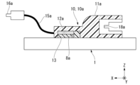
- FIG. 2 is a side cross-sectional view of the positive electrode terminal box 10a taken along line II-II in FIG.
- the positive electrode terminal box 10a has a positive electrode terminal box main body (terminal box main body) 11a, a first positive electrode connecting terminal (first connecting terminal) 16a, and a second positive electrode connecting terminal (second connecting terminal) 18a.
- the positive terminal box body 11a is formed from a resin material or the like.
- the positive terminal box body 11a has a positive electrode connection part (connection part) 12a inside.
- the positive electrode connection part 12a is a connection pad or the like.
- the positive electrode connection part 12a is electrically connected to the positive electrode terminal 8a of the solar cell element 1 by solder or the like.
- the connection part between the positive electrode connection part 12a and the positive electrode terminal 8a is sealed with a potting material 13.
- the potting material 13 is a resin adhesive or the like.
- the positive terminal box body 11a is attached to the solar cell element 1 by the potting material 13.
- the longitudinal direction of the positive terminal box body 11a is approximately parallel to the X direction.
- the first positive electrode connection terminal 16a is disposed at the +X-direction end of the positive electrode cable (cable) 15a.
- the positive electrode cable 15a extends outward from the +X-direction end of the positive electrode terminal box main body 11a.
- the -X-direction end of the positive electrode cable 15a is connected to the positive electrode connection part 12a.
- the first positive electrode connection terminal 16a is electrically connected to the positive electrode connection part 12a via the positive electrode cable 15a.
- the length of the positive electrode cable 15a is equal to the width of the solar cell element 1 in the X-direction.
- the second positive electrode connection terminal 18a is a connection port and is formed on the outer surface of the positive electrode terminal box body 11a in the -X direction.
- the second positive electrode connection terminal 18a is electrically connected to the positive electrode connection part 12a by wiring or the like (not shown).
- the first positive electrode connection terminal 16a and the second positive electrode connection terminal 18a are connectors based on standards such as MC4.
- the first positive electrode connection terminal 16a and the second positive electrode connection terminal 18a can be connected to each other.
- the first positive electrode connection terminal 16a is a plug (pin, male)
- the second positive electrode connection terminal 18a is a jack (socket, receptacle, female).
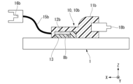
- FIG. 3 is a side cross-sectional view of the negative electrode terminal box 10b taken along line III-III in FIG.
- the negative electrode terminal box 10b has a negative electrode terminal box main body (terminal box main body) 11b, a first negative electrode connecting terminal (first connecting terminal) 16b, and a second negative electrode connecting terminal (second connecting terminal) 18b.
- the negative terminal box body 11b is formed from a resin material or the like.
- the negative terminal box body 11b has a negative electrode connection part (connection part) 12b inside.
- the negative electrode connection part 12b is a connection pad or the like.
- the negative electrode connection part 12b is electrically connected to the negative electrode terminal 8b of the solar cell element 1 by solder or the like.
- the connection part between the negative electrode connection part 12b and the negative electrode terminal 8b is sealed with a potting material 13.
- the potting material 13 is a resin adhesive or the like.
- the negative terminal box body 11b is attached to the solar cell element 1 by the potting material 13.
- the longitudinal direction of the negative terminal box body 11b is approximately parallel to the X direction.
- the first negative electrode connection terminal 16b is disposed at the +X-direction end of the negative electrode cable (cable) 15b.
- the negative electrode cable 15b extends outward from the +X-direction end of the negative electrode terminal box main body 11b.
- the -X-direction end of the negative electrode cable 15b is connected to the negative electrode connection part 12b.
- the first negative electrode connection terminal 16b is electrically connected to the negative electrode connection part 12b via the negative electrode cable 15b.
- the length of the negative electrode cable 15b is equal to the width of the solar cell element 1 in the X-direction.
- the second negative electrode connection terminal 18b is a connection port and is formed on the outer surface of the negative electrode terminal box body 11b in the -X direction.
- the second negative electrode connection terminal 18b is electrically connected to the negative electrode connection part 12b by wiring or the like (not shown).
- the first negative electrode connection terminal 16b and the second negative electrode connection terminal 18b are connectors based on standards such as MC4.
- the first negative electrode connection terminal 16b and the second negative electrode connection terminal 18b can be connected to each other.
- the first negative electrode connection terminal 16b is a jack (socket, receptacle, female)
- the second negative electrode connection terminal 18b is a plug (pin, male).
- the first negative electrode connection terminal 16b may be a plug (pin, male) and the second negative electrode connection terminal 18b may be a jack (socket, receptacle, female), but in that case, the first positive electrode connection terminal 16a must be changed to a jack (socket, receptacle, female) and the second positive electrode connection terminal 18a to a plug (pin, male).
- the first positive electrode connection terminal 16a of the positive electrode terminal box 10a is a plug based on a standard such as MC4.
- the first negative electrode connection terminal 16b of the negative electrode terminal box 10b is a jack based on a standard such as MC4.
- the first positive electrode connection terminal 16a and the first negative electrode connection terminal 16b can be connected.
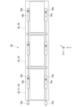
- FIG. 4 is a plan view of the parallel connection body 30.
- the parallel connection body 30 is formed by connecting multiple solar cell units 20 in parallel.
- the multiple solar cell units 20 are arranged side by side in the X direction.
- a pair of solar cell units 20 adjacent to each other in the X direction is defined as a first solar cell unit 21 and a second solar cell unit 22.
- the first solar cell unit 21 is in the +X direction, and the second solar cell unit 22 is in the -X direction.
- the second positive electrode connection terminal 18a of the first solar cell unit 21 is connected to the first positive electrode connection terminal 16a of the second solar cell unit 22.
- the second negative electrode connection terminal 18b of the first solar cell unit 21 is connected to the first negative electrode connection terminal 16b of the second solar cell unit 22.
- the multiple solar cell units 20 include a first end solar cell unit 28 and a second end solar cell unit 29.
- the first end solar cell unit 28 is at the end in the +X direction
- the second end solar cell unit 29 is at the end in the -X direction.
- the parallel connection body 30 is connected to the outside via the first positive electrode connection terminal 16a and the first negative electrode connection terminal 16b of the first end solar cell unit 28.
- the parallel connector 30 has a positive electrode cap 30a and a negative electrode cap 30b.
- the positive electrode cap 30a is attached to the second positive electrode connection terminal 18a of the second end solar cell unit 29.
- the negative electrode cap 30b is attached to the second negative electrode connection terminal 18b of the second end solar cell unit 29.
- the positive electrode cap 30a and the negative electrode cap 30b can be commercially available products based on standards such as MC4.
- the positive electrode cap 30a and the negative electrode cap 30b suppress leakage current from the parallel connector 30.
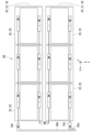
- FIG. 5 is a plan view of the solar cell unit connection body 40 in the first embodiment.
- the solar cell unit connection body 40 is formed by connecting multiple parallel connections 30 in series.
- the multiple parallel connections 30 are arranged side by side in the Y direction.
- a pair of parallel connections 30 adjacent to each other in the Y direction are referred to as a first parallel connection body 31 and a second parallel connection body 32.
- the first parallel connection body 31 is in the +Y direction
- the second parallel connection body 32 is in the -Y direction.
- the first negative electrode connection terminal 16b of the first end solar cell unit 28 of the first parallel connection body 31 is connected to the first positive electrode connection terminal 16a of the first end solar cell unit 28 of the second parallel connection body 32.
- the multiple parallel connections 30 include a first end parallel connection 38 and a second end parallel connection 39.
- the first end parallel connection 38 is at the end in the +Y direction
- the second end parallel connection 39 is at the end in the -Y direction.
- the solar cell unit connector 40 has a positive electrode cord 40a and a negative electrode cord 40b.
- the positive electrode cord 40a is connected to the first positive electrode connection terminal 16a of the first end solar cell unit 28 of the first end parallel connector 38.
- the negative electrode cord 40b is connected to the first negative electrode connection terminal 16b of the first end solar cell unit 28 of the second end parallel connector 39.
- the positive electrode cord 40a and the negative electrode cord 40b are arranged in the +X direction of the solar cell unit connector 40.
- the solar cell unit connector 40 is connected to the outside by the positive electrode cord 40a and the negative electrode cord 40b.
- the solar cell unit 20 of the embodiment has the solar cell element 1, the positive electrode terminal box 10a, and the negative electrode terminal box 10b.
- the solar cell element 1 includes a perovskite semiconductor and has the positive electrode terminal 8a and the negative electrode terminal 8b.
- the positive electrode terminal box 10a is connected to the positive electrode terminal 8a, and the negative electrode terminal box 10b is connected to the negative electrode terminal 8b.
- the positive terminal box 10a has a positive terminal box main body 11a, a first positive electrode connection terminal 16a, and a second positive electrode connection terminal 18a.
- the positive terminal box main body 11a is attached to the solar cell element 1 and has a positive electrode connection portion 12a that is electrically connected to the positive electrode terminal 8a of the solar cell element 1.
- the first positive electrode connection terminal 16a is electrically connected to the positive electrode connection portion 12a and is disposed at the tip of a positive electrode cable 15a that extends from the positive terminal box main body 11a to the outside.
- the second positive electrode connection terminal 18a is electrically connected to the positive electrode connection portion 12a, is formed on the outer surface of the positive terminal box main body 11a, and can be connected to the first positive electrode connection terminal 16a.
- the negative terminal box 10b has a negative terminal box main body 11b, a first negative electrode connection terminal 16b, and a second negative electrode connection terminal 18b.
- the negative terminal box main body 11b is attached to the solar cell element 1 and has a negative electrode connection part 12b that is electrically connected to the negative electrode terminal 8b of the solar cell element 1.
- the first negative electrode connection terminal 16b is electrically connected to the negative electrode connection part 12b and is disposed at the tip of a negative electrode cable 15b that extends from the negative terminal box main body 11b to the outside.
- the second negative electrode connection terminal 18b is electrically connected to the negative electrode connection part 12b, is formed on the outer surface of the negative terminal box main body 11b, and can be connected to the first negative electrode connection terminal 16b.
- the first positive electrode connection terminal 16a and the first negative electrode connection terminal 16b are connectable to each other.
- the amount of current generated by the solar cell element 1 including the perovskite semiconductor is small, and in practical use, a configuration in which multiple solar cell units 20 are connected in parallel is assumed.
- connection members are suitable for a configuration in which solar cell units are connected in series, and if a parallel connection is to be realized using these members, for example, a large number of special branch cables must be used, which is disadvantageous in terms of cost, number of parts, and effort of connection.
- the positive cable 15a of one solar cell unit 20 is extended, and the first positive electrode connection terminal 16a of one solar cell unit 20 is connected to the second positive electrode connection terminal 18a of the adjacent solar cell unit 20.
- the negative cable 15b of one solar cell unit 20 is extended, and the first negative electrode connection terminal 16b of one solar cell unit 20 is connected to the second negative electrode connection terminal 18b of the adjacent solar cell unit 20.
- Multiple solar cell units 20 can be easily connected in parallel.
- the number of solar cell units 20 connected in parallel can be easily changed.
- Special branch cables, etc. for connecting multiple solar cell units 20 in parallel are not required. This also helps prevent mistakes during construction, which contributes to shortening the construction period. As a result, the cost of the solar cell unit connector 40 can be reduced.
- the positive terminal box 10a and the negative terminal box 10b are each composed of two connection terminals and one cable.
- the structures of the positive terminal box 10a and the negative terminal box 10b are simple, and the costs of the terminal box 10 and the solar cell unit 20 can be reduced.
- the same positive terminal box 10a and negative terminal box 10b are attached to all the solar cell units 20. By mass-producing the positive terminal box 10a and the negative terminal box 10b, the costs of the terminal box 10 and the solar cell units 20 can be reduced.
- the first positive electrode connecting terminal 16a and the first negative electrode connecting terminal 16b have different shapes. Misconnections of the multiple solar cell units 20 are suppressed.
- the solar cell element 1 has a scribe line 5 that extends in the X direction.
- the direction parallel to the surface of the solar cell element 1 and perpendicular to the X direction is the Y direction.
- the positive electrode terminal 8a is disposed at the end of the solar cell element 1 in the +Y direction.
- the negative electrode terminal 8b is disposed at the end of the solar cell element 1 in the -Y direction.
- the positive terminal box 10a and the negative terminal box 10b are integrated, wiring is required to draw one of the positive terminal 8a and the negative terminal 8b close to the other terminal.
- the positive terminal box 10a and the negative terminal box 10b are separate, and wiring is not required. There is no need for an insulating film to be placed between the wiring and the solar cell element 1, and no work is required to align the insulating film. The cost of the solar cell unit 20 can be reduced.
- the positive cable 15a extends from the +X direction of the positive terminal box body 11a to the outside.
- the second positive connection terminal 18a is formed in the -X direction of the positive terminal box body 11a.
- the negative cable 15b extends from the +X direction of the negative terminal box body 11b to the outside.
- the second negative connection terminal 18b is formed in the -X direction of the negative terminal box body 11b.
- the positive electrode terminal box 10a and the negative electrode terminal box 10b are arranged parallel to the scribe line 5.
- the positive electrode terminal box 10a and the negative electrode terminal box 10b can be arranged close to the semiconductor layer 3.
- the lengths of the positive electrode terminal 8a and the negative electrode terminal 8b are shortened.
- the cost of the solar cell unit 20 can be reduced.
- both the positive cable 15a and the negative cable 15b extend in the +Y direction, which makes it easier to connect the multiple solar cell units 20.
- the solar cell unit connection body 40 has a parallel connection body 30, a positive pole cord 40a, and a negative pole cord 40b.
- a plurality of the above-described solar cell units 20 are arranged side by side in the X direction.
- the solar cell unit 20 in the +X direction is defined as a first solar cell unit 21
- the solar cell unit 20 in the -X direction is defined as a second solar cell unit 22.
- the second positive electrode connection terminal 18a of the first solar cell unit 21 and the first positive electrode connection terminal 16a of the second solar cell unit 22 are connected.
- the second negative electrode connection terminal 18b of the first solar cell unit 21 and the first negative electrode connection terminal 16b of the second solar cell unit 22 are connected.
- a plurality of parallel connections 30 are arranged side by side in the Y direction.
- the parallel connection 30 in the +Y direction is referred to as a first parallel connection 31, and the parallel connection 30 in the -Y direction is referred to as a second parallel connection 32.
- the first negative electrode connection terminal 16b of the solar cell unit 20 at the end of the first parallel connection 31 in the +X direction is connected to the first positive electrode connection terminal 16a of the solar cell unit 20 at the end of the second parallel connection 32 in the +X direction.
- the positive electrode cord 40a is connected to the first positive electrode connection terminal 16a of the solar cell unit 20 at the end in the +X direction of the parallel connector 30 at the end in the +Y direction.
- the negative electrode cord 40b is connected to the first negative electrode connection terminal 16b of the solar cell unit 20 at the end in the +X direction of the parallel connector 30 at the end in the -Y direction.
- the number of solar cell units 20 included in the parallel connection body 30 can be easily changed.
- the number of parallel connection bodies 30 included in the solar cell unit connection body 40 can be easily changed.
- the cost of the solar cell unit connection body 40 can be reduced.
- Both the positive electrode cord 40a and the negative electrode cord 40b are arranged in the +X direction of the solar cell unit connection body 40.
- the solar cell unit connection body 40 can be easily connected to the outside.
- the solar cell unit connection body 40 has a positive electrode cap 30a attached to the second positive electrode connection terminal 18a and a negative electrode cap 30b attached to the second negative electrode connection terminal 18b of the solar cell unit 20 at the end of the parallel connection body 30 in the -X direction. Electric leakage from the parallel connection body 30 of the solar cell unit connection body 40 is suppressed.
- FIG. 6 is a plan view of a solar cell unit connection body 40 in a first modified example of the first embodiment.
- the solar cell unit connection body 40 in the first embodiment has a positive electrode cap 30a and a negative electrode cap 30b.
- the solar cell unit connection body 40 in the first modified example has a bypass diode 35. Descriptions of the first modified example regarding parts that are similar to the first embodiment may be omitted.
- the parallel connection body 30 has a bypass diode 35.
- the bypass diode 35 is connected between the second positive electrode connection terminal 18a and the second negative electrode connection terminal 18b of the second end solar cell unit 29 at the end of the parallel connection body 30 in the -X direction.
- the current generated in the remaining parallel connections 30 flows through the bypass diodes of some of the parallel connections 30.
- the current can be extracted from the solar cell unit connection 40.
- the bypass diode 35 can be easily connected to the parallel connection body 30. No special cables or the like are required for connecting the bypass diode 35 to the parallel connection body 30. The cost of the solar cell unit connection body 40 can be reduced.
- Second Embodiment 7 is a plan view of the solar cell unit 20 in the second embodiment.
- the positive cable 15a and the negative cable 15b extend in the same direction.
- the positive cable 15a and the negative cable 15b extend in opposite directions. Descriptions of the second embodiment regarding the same parts as those of the first embodiment may be omitted.
- the negative electrode terminal box 10b of the second embodiment is attached to the solar cell element 1 in the same manner as in the first embodiment.
- the positive electrode terminal box 10a of the second embodiment is attached to the solar cell element 1, inverted in the X direction from the first embodiment.
- the positive electrode cable 15a extends outward from the -X direction end of the positive electrode terminal box main body 11a.
- the first positive electrode connection terminal 16a is disposed at the -X direction tip of the positive electrode cable 15a.
- the second positive electrode connection terminal 18a is formed on the +X direction outer surface of the positive electrode terminal box main body 11a.
- FIG. 8 is a plan view of the parallel connection body 30.
- the three solar cell units 20 arranged in the X direction are the first solar cell unit 21, the second solar cell unit 22, and the third solar cell unit 23.
- the first solar cell unit 21 is in the +X direction
- the third solar cell unit 23 is in the -X direction
- the second solar cell unit 22 is in the center.
- the first positive electrode connection terminal 16a of the second solar cell unit 22 is connected to the second positive electrode connection terminal 18a of the third solar cell unit 23.
- the first negative electrode connection terminal 16b of the second solar cell unit 22 is connected to the second negative electrode connection terminal 18b of the first solar cell unit 21.
- the parallel connection body 30 is connected to the outside via the first positive electrode connection terminal 16 a of the second end solar cell unit 29 and the first negative electrode connection terminal 16 b of the first end solar cell unit 28 .
- the positive electrode cap 30a is attached to the second positive electrode connection terminal 18a of the first end solar cell unit 28.
- the negative electrode cap 30b is attached to the second negative electrode connection terminal 18b of the second end solar cell unit 29.
- FIG. 9 is a plan view of the solar cell unit connection body 40 in the second embodiment.
- the positive electrode cap 30a attached to the second positive electrode connection terminal 18a of the first end solar cell unit 28 is removed.
- the negative electrode cap 30b is attached to the first positive electrode connection terminal 16a of the second end solar cell unit 29.
- the first negative electrode connection terminal 16b of the first end solar cell unit 28 of the first parallel connection body 31 and the second positive electrode connection terminal 18a of the first end solar cell unit 28 of the second parallel connection body 32 are connected via a conversion connector 45.
- both ends of the conversion connector 45 are plugs (pins, male).
- the conversion connector 45 a commercially available product based on standards such as MC4 can be used.
- the positive pole cord 40a is connected to the first positive pole connection terminal 16a of the second end solar cell unit 29 of the first end parallel connector 38.
- the negative pole cord 40b is connected to the first negative pole connection terminal 16b of the first end solar cell unit 28 of the second end parallel connector 39.
- the costs of the terminal box 10, the solar cell unit 20, and the solar cell unit connector 40 can be reduced.
- the first positive electrode connection terminal 16a is a plug
- the second positive electrode connection terminal 18a is a jack
- the first negative electrode connection terminal 16b is a jack
- the second negative electrode connection terminal 18b is a plug
- the first positive electrode connection terminal 16a may be a jack
- the second positive electrode connection terminal 18a may be a plug
- the first negative electrode connection terminal 16b may be a plug
- the second negative electrode connection terminal 18b may be a jack.
- the terminal boxes 10a, 10b have terminal box bodies 11a, 11b, first connection terminals 16a, 16b, and second connection terminals 18a, 18b.
- the first connection terminals 16a, 16b are disposed at the ends of cables 15a, 15b extending outward from the terminal box bodies 11a, 11b.
- the second connection terminals 18a, 18b are formed on the outer surfaces of the terminal box bodies 11a, 11b. This makes it possible to reduce the costs of the terminal box 10, the solar cell unit 20, and the solar cell unit connector 40.
Landscapes
- Photovoltaic Devices (AREA)
Priority Applications (5)
| Application Number | Priority Date | Filing Date | Title |
|---|---|---|---|
| CN202380091111.5A CN120677634A (zh) | 2023-05-10 | 2023-05-10 | 端子箱、太阳能电池单元以及太阳能电池单元连接体 |
| EP23936591.9A EP4712339A1 (en) | 2023-05-10 | 2023-05-10 | Terminal box, solar cell unit, and solar cell unit connection body |
| JP2025519246A JPWO2024232038A1 (https=) | 2023-05-10 | 2023-05-10 | |
| PCT/JP2023/017536 WO2024232038A1 (ja) | 2023-05-10 | 2023-05-10 | 端子箱、太陽電池ユニットおよび太陽電池ユニット接続体 |
| US19/269,180 US20250343506A1 (en) | 2023-05-10 | 2025-07-15 | Terminal box, solar cell unit, and solar cell unit connection body |
Applications Claiming Priority (1)
| Application Number | Priority Date | Filing Date | Title |
|---|---|---|---|
| PCT/JP2023/017536 WO2024232038A1 (ja) | 2023-05-10 | 2023-05-10 | 端子箱、太陽電池ユニットおよび太陽電池ユニット接続体 |
Related Child Applications (1)
| Application Number | Title | Priority Date | Filing Date |
|---|---|---|---|
| US19/269,180 Continuation US20250343506A1 (en) | 2023-05-10 | 2025-07-15 | Terminal box, solar cell unit, and solar cell unit connection body |
Publications (1)
| Publication Number | Publication Date |
|---|---|
| WO2024232038A1 true WO2024232038A1 (ja) | 2024-11-14 |
Family
ID=93431460
Family Applications (1)
| Application Number | Title | Priority Date | Filing Date |
|---|---|---|---|
| PCT/JP2023/017536 Ceased WO2024232038A1 (ja) | 2023-05-10 | 2023-05-10 | 端子箱、太陽電池ユニットおよび太陽電池ユニット接続体 |
Country Status (5)
| Country | Link |
|---|---|
| US (1) | US20250343506A1 (https=) |
| EP (1) | EP4712339A1 (https=) |
| JP (1) | JPWO2024232038A1 (https=) |
| CN (1) | CN120677634A (https=) |
| WO (1) | WO2024232038A1 (https=) |
Citations (9)
| Publication number | Priority date | Publication date | Assignee | Title |
|---|---|---|---|---|
| JPH08186280A (ja) * | 1994-12-28 | 1996-07-16 | Showa Shell Sekiyu Kk | 太陽電池モジュールおよび太陽電池装置 |
| JP3572265B2 (ja) | 2001-03-26 | 2004-09-29 | 三菱重工業株式会社 | 太陽電池モジュール、太陽光発電システム及びその施工方法 |
| WO2007015346A1 (ja) | 2005-08-02 | 2007-02-08 | Honda Motor Co., Ltd. | 太陽光発電装置 |
| JP2009302561A (ja) * | 2008-05-15 | 2009-12-24 | Kaneka Corp | 太陽電池モジュール、並びに、太陽電池アレイ |
| KR101077110B1 (ko) * | 2011-04-19 | 2011-10-26 | 김영춘 | 태양광 모듈의 정션박스 연결장치 |
| WO2013121840A1 (ja) * | 2012-02-14 | 2013-08-22 | 本田技研工業株式会社 | 太陽電池モジュール |
| JP2015154049A (ja) * | 2014-02-19 | 2015-08-24 | 三菱化学株式会社 | 薄膜太陽電池モジュール |
| JP2021132233A (ja) * | 2016-09-21 | 2021-09-09 | 株式会社東芝 | 太陽電池モジュール及び太陽光発電システム |
| WO2022059366A1 (ja) * | 2020-09-17 | 2022-03-24 | 株式会社東芝 | 太陽電池、および太陽電池システム |
-
2023
- 2023-05-10 JP JP2025519246A patent/JPWO2024232038A1/ja active Pending
- 2023-05-10 EP EP23936591.9A patent/EP4712339A1/en active Pending
- 2023-05-10 CN CN202380091111.5A patent/CN120677634A/zh active Pending
- 2023-05-10 WO PCT/JP2023/017536 patent/WO2024232038A1/ja not_active Ceased
-
2025
- 2025-07-15 US US19/269,180 patent/US20250343506A1/en active Pending
Patent Citations (9)
| Publication number | Priority date | Publication date | Assignee | Title |
|---|---|---|---|---|
| JPH08186280A (ja) * | 1994-12-28 | 1996-07-16 | Showa Shell Sekiyu Kk | 太陽電池モジュールおよび太陽電池装置 |
| JP3572265B2 (ja) | 2001-03-26 | 2004-09-29 | 三菱重工業株式会社 | 太陽電池モジュール、太陽光発電システム及びその施工方法 |
| WO2007015346A1 (ja) | 2005-08-02 | 2007-02-08 | Honda Motor Co., Ltd. | 太陽光発電装置 |
| JP2009302561A (ja) * | 2008-05-15 | 2009-12-24 | Kaneka Corp | 太陽電池モジュール、並びに、太陽電池アレイ |
| KR101077110B1 (ko) * | 2011-04-19 | 2011-10-26 | 김영춘 | 태양광 모듈의 정션박스 연결장치 |
| WO2013121840A1 (ja) * | 2012-02-14 | 2013-08-22 | 本田技研工業株式会社 | 太陽電池モジュール |
| JP2015154049A (ja) * | 2014-02-19 | 2015-08-24 | 三菱化学株式会社 | 薄膜太陽電池モジュール |
| JP2021132233A (ja) * | 2016-09-21 | 2021-09-09 | 株式会社東芝 | 太陽電池モジュール及び太陽光発電システム |
| WO2022059366A1 (ja) * | 2020-09-17 | 2022-03-24 | 株式会社東芝 | 太陽電池、および太陽電池システム |
Also Published As
| Publication number | Publication date |
|---|---|
| US20250343506A1 (en) | 2025-11-06 |
| CN120677634A (zh) | 2025-09-19 |
| JPWO2024232038A1 (https=) | 2024-11-14 |
| EP4712339A1 (en) | 2026-03-18 |
Similar Documents
| Publication | Publication Date | Title |
|---|---|---|
| US7833033B2 (en) | Solar panel junction box and components thereof | |
| CN109792028B (zh) | 连接模块 | |
| US7723609B2 (en) | Terminal box for solar battery module | |
| CN101584050A (zh) | 用于光伏模块的电缆连接器和安装方法 | |
| CN106165117B (zh) | 用于具有改进的电池连接拓扑的光伏模块的背侧接触层 | |
| EP2858124B1 (en) | Bridged solar cell and solar power generation system | |
| KR20120059049A (ko) | 배터리모듈 구조 | |
| US20120312347A1 (en) | Solar module and photovoltaic array | |
| US20190028057A1 (en) | Solar module and method for fabricating the same | |
| CN102237440B (zh) | 光电装置及其制造方法 | |
| WO2024232038A1 (ja) | 端子箱、太陽電池ユニットおよび太陽電池ユニット接続体 | |
| US12199207B2 (en) | Solar cell module | |
| JP2024518279A (ja) | 小型セルコネクタ配列体を有する高電圧蓄電装置 | |
| JP4416712B2 (ja) | 太陽光発電装置 | |
| JPS6314471Y2 (https=) | ||
| JP2004221151A (ja) | 屋根材一体型太陽電池モジュール | |
| CN112290884A (zh) | 一种串联式集成化分体式光伏组件接线盒及光伏组件 | |
| CN115842503B (zh) | Bipv光伏瓦片 | |
| CN111710741B (zh) | 一种光伏发电装置 | |
| CN102214718A (zh) | 太阳能电池装置 | |
| US20240072398A1 (en) | Power supply device and method for producing same | |
| CN110460304B (zh) | 光伏组件、系统和光伏幕墙 | |
| JP7841154B1 (ja) | 太陽光発電システム | |
| JP2004241789A (ja) | 太陽光発電システム、太陽電池モジュール、及び太陽光発電システムの施工方法 | |
| WO2025022532A1 (ja) | 太陽電池接続体 |
Legal Events
| Date | Code | Title | Description |
|---|---|---|---|
| 121 | Ep: the epo has been informed by wipo that ep was designated in this application |
Ref document number: 23936591 Country of ref document: EP Kind code of ref document: A1 |
|
| WWE | Wipo information: entry into national phase |
Ref document number: 2025519246 Country of ref document: JP |
|
| WWE | Wipo information: entry into national phase |
Ref document number: 202380091111.5 Country of ref document: CN |
|
| WWE | Wipo information: entry into national phase |
Ref document number: 202517066850 Country of ref document: IN |
|
| WWP | Wipo information: published in national office |
Ref document number: 202517066850 Country of ref document: IN |
|
| WWP | Wipo information: published in national office |
Ref document number: 202380091111.5 Country of ref document: CN |
|
| WWE | Wipo information: entry into national phase |
Ref document number: 2023936591 Country of ref document: EP |
|
| NENP | Non-entry into the national phase |
Ref country code: DE |
|
| ENP | Entry into the national phase |
Ref document number: 2023936591 Country of ref document: EP Effective date: 20251210 |
|
| ENP | Entry into the national phase |
Ref document number: 2023936591 Country of ref document: EP Effective date: 20251210 |
|
| ENP | Entry into the national phase |
Ref document number: 2023936591 Country of ref document: EP Effective date: 20251210 |
|
| ENP | Entry into the national phase |
Ref document number: 2023936591 Country of ref document: EP Effective date: 20251210 |
|
| ENP | Entry into the national phase |
Ref document number: 2023936591 Country of ref document: EP Effective date: 20251210 |
|
| ENP | Entry into the national phase |
Ref document number: 2023936591 Country of ref document: EP Effective date: 20251210 |
|
| ENP | Entry into the national phase |
Ref document number: 2023936591 Country of ref document: EP Effective date: 20251210 |
|
| ENP | Entry into the national phase |
Ref document number: 2023936591 Country of ref document: EP Effective date: 20251210 |
|
| ENP | Entry into the national phase |
Ref document number: 2023936591 Country of ref document: EP Effective date: 20251210 |