WO2024232012A1 - 通信制御装置、及び通信制御方法、及びプログラム - Google Patents
通信制御装置、及び通信制御方法、及びプログラム Download PDFInfo
- Publication number
- WO2024232012A1 WO2024232012A1 PCT/JP2023/017422 JP2023017422W WO2024232012A1 WO 2024232012 A1 WO2024232012 A1 WO 2024232012A1 JP 2023017422 W JP2023017422 W JP 2023017422W WO 2024232012 A1 WO2024232012 A1 WO 2024232012A1
- Authority
- WO
- WIPO (PCT)
- Prior art keywords
- optical
- switching
- splitter
- communication
- spc
- Prior art date
- Legal status (The legal status is an assumption and is not a legal conclusion. Google has not performed a legal analysis and makes no representation as to the accuracy of the status listed.)
- Ceased
Links
Images




Classifications
-
- H—ELECTRICITY
- H04—ELECTRIC COMMUNICATION TECHNIQUE
- H04B—TRANSMISSION
- H04B10/00—Transmission systems employing electromagnetic waves other than radio-waves, e.g. infrared, visible or ultraviolet light, or employing corpuscular radiation, e.g. quantum communication
- H04B10/27—Arrangements for networking
Definitions
- the embodiments relate to a communication control device, a communication control method, and a program.
- PON passive optical network
- OLT optical line terminal
- ONU optical network units
- the number of ONUs accommodated may differ between different PONs.
- the traffic volume of each of the multiple ONUs may differ from one another. For this reason, it is difficult to equalize the bandwidth allocated to ONUs between different PONs.
- the present invention was made with the above in mind, and its purpose is to provide a means to equalize the bandwidth allocated to ONUs across different PONs.
- a communication control device controls communication in an optical communication system.
- the optical communication system includes a first terminal device, a second terminal device, a first splitter that splits an optical signal from the first terminal device, a second splitter that splits an optical signal from the second terminal device, a plurality of third terminal devices, a switching device provided between the first splitter and the second splitter and the plurality of third terminal devices and configured to execute a switching operation for switching communication between at least one of the plurality of third terminal devices and the first terminal device via the first splitter to communication between the second terminal device and the first terminal device via the second splitter, and the communication control device.
- the communication control device includes an acquisition unit that acquires a usage status of communication via the first splitter and the second splitter by the plurality of third terminal devices, a selection unit that selects a switching target from the plurality of third terminal devices based on the acquired usage status, and an instruction unit that instructs the switching device to execute the switching operation for the selected switching target.
- a means can be provided for leveling out the bandwidth allocated to ONUs across different PONs.
- FIG. 1 is a block diagram illustrating an example of an optical communication system according to an embodiment.
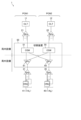
- FIG. 2 is a block diagram showing an example of a configuration of a portion including a switching device in an optical communication system according to an embodiment.
- FIG. 3 is a block diagram illustrating an example of a hardware configuration of the communication control device according to the embodiment.
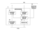
- FIG. 4 is a block diagram illustrating an example of a functional configuration of the communication control device according to the embodiment.
- FIG. 5 is a diagram illustrating an example of a data structure of a communication usage status DB used in the optical communication system according to the embodiment.
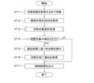
- FIG. 6 is a flowchart illustrating an example of a series of processes including a switching operation in the optical communication system according to the embodiment.
- FIG. 7 is a flowchart illustrating an example of a switching target selection process included in the switching operation in the optical communication system according to the embodiment.
- Fig. 1 is a block diagram showing an example of the configuration of the optical communication system according to the embodiment.
- the optical communication system 1 is an optical communication network including a communication control device 5 and multiple PONs (PON1 and PON2).
- the communication control device 5 is, for example, a server installed in a telecommunications carrier's station.
- the communication control device 5 is configured to control the operation of multiple PONs.
- PON1 and PON2 are passive optical networks. PON1 and PON2 provide information to users via the network NW. The number of users to which each of PON1 and PON2 provides information is arbitrary, but may be 32, for example.
- PON1 includes OLT 11, SPa 21, multiple SPbs 31, 32, 33, and 34, multiple ONUs 41 ⁇ 1: N1 >, 42 ⁇ 1: N2 >, 43 ⁇ 1: N3 >, and 44 ⁇ 1: N4 >, and a part of switching device 50 (1 ⁇ N1 to N4 ⁇ 8).
- PON2 includes OLT 12, SPa 22, multiple SPbs 35, 36, 37, and 38, multiple ONUs 45 ⁇ 1: N5 >, 46 ⁇ 1: N6 >, 47 ⁇ 1: N7 >, and 48 ⁇ 1: N8 >, and a part of switching device 50 (1 ⁇ N5 to N8 ⁇ 8 ).
- the plurality of ONUs 45 ⁇ 1:Nx> refers to Nx ONUs 45 ⁇ 1>, . . . , and 45 ⁇ Nx> (x is an integer).
- OLT11 and OLT12 are each optical line termination devices installed within a telecommunications carrier's office.
- OLT11 controls the communication of information between network NW and PON1.
- OLT11 is connected to SPa21 via an optical cable.
- OLT12 controls the communication of information between network NW and PON2. OLT12 is connected to SPa22 via an optical cable.
- Each of SPa21 and SPa22 is a passive element that does not require a power source.
- Each of SPa21 and SPa22 is, for example, an optical splitter with a maximum of four branches.
- the SPa21 branches the optical signal received from the OLT11.
- the optical signals branched by the SPa21 are transmitted to the switching device 50 via four different optical cables.
- the SPa21 also merges the four types of optical signals transmitted from the switching device 50 via the four different optical cables.
- the optical signals merged by the SPa21 are transmitted to the OLT11 via a single optical cable.
- the SPa 22 branches the optical signal received from the OLT 12.
- the optical signals branched by the SPa 22 are transmitted to the switching device 50 via four different optical cables.
- the SPa 22 also merges the four types of optical signals transmitted from the switching device 50 via the four different optical cables.
- the optical signal merged by the SPa 22 is transmitted to the OLT 12 via one optical cable. Note that the number of optical cables that the SPa 22 branches and merges is not limited to four, and any integer equal to or greater than two may be applied.
- Each of SPb31-38 is a passive element that does not require a power source.
- Each of SPb31-38 is, for example, an optical splitter with up to eight branches.
- Each of SPb31-38 branches the optical signal received from the switching device 50.
- the optical signals branched by SPb31 are transmitted to ONU41 ⁇ 1:N 1 > via N 1 different optical cables.
- SPb31 also combines N 1 types of optical signals transmitted from ONU41 ⁇ 1:N 1 > via N 1 different optical cables.
- the optical signals combined by SPb31 are transmitted to the switching device 50 via one optical cable.
- the optical signals branched by SPb 32 are transmitted to ONU 42 ⁇ 1:N 2 > via N 2 different optical cables.
- SPb 32 also combines N 2 types of optical signals transmitted from ONU 42 ⁇ 1:N 2 > via N 2 different optical cables.
- the optical signals combined by SPb 32 are transmitted to the switching device 50 via one optical cable.
- the optical signals branched by SPb 33 are transmitted to ONU 43 ⁇ 1: N3 > via N3 different optical cables.
- SPb 33 also combines N3 types of optical signals transmitted from ONU 43 ⁇ 1: N3 > via N3 different optical cables.
- the optical signals combined by SPb 33 are transmitted to the switching device 50 via one optical cable.
- the optical signals branched by SPb 34 are transmitted to ONUs 44 ⁇ 1: N4 > via N4 different optical cables.
- SPb 34 also combines N4 types of optical signals transmitted from ONUs 44 ⁇ 1: N4 > via N4 different optical cables.
- the optical signals combined by SPb 34 are transmitted to the switching device 50 via one optical cable.
- the optical signals branched by SPb 35 are transmitted to ONU 45 ⁇ 1: N5 > via N5 different optical cables.
- SPb 35 also combines N5 types of optical signals transmitted from ONU 45 ⁇ 1: N5 > via N5 different optical cables.
- the optical signals combined by SPb 35 are transmitted to the switching device 50 via one optical cable.
- the optical signals branched by SPb 36 are transmitted to ONUs 46 ⁇ 1: N6 > via N6 different optical cables.
- SPb 36 also combines N6 types of optical signals transmitted from ONUs 46 ⁇ 1: N6 > via N6 different optical cables.
- the optical signals combined by SPb 36 are transmitted to the switching device 50 via one optical cable.
- the optical signals branched by SPb 37 are transmitted to ONU 47 ⁇ 1: N7 > via N7 different optical cables.
- SPb 37 also combines N7 types of optical signals transmitted from ONU 47 ⁇ 1: N7 > via N7 different optical cables.
- the optical signals combined by SPb 37 are transmitted to the switching device 50 via one optical cable.
- the optical signals branched by SPb 38 are transmitted to ONUs 48 ⁇ 1:N 8 > via N 8 different optical cables.
- SPb 38 also combines N 8 types of optical signals transmitted from ONUs 48 ⁇ 1:N 8 > via N 8 different optical cables.
- the optical signals combined by SPb 38 are transmitted to the switching device 50 via one optical cable.
- Each of the ONUs 41 ⁇ 1:N 1 > to 44 ⁇ 1:N 8 > is an optical line terminal installed outside a telecommunications carrier's office (on the user side).
- Each of ONUs 41 ⁇ 1:N 1 > to 44 ⁇ 1:N 4 > controls the communication of information between users and PON 1.
- ONU 41 ⁇ 1:N 1 > is connected to SPb 31 via different optical cables.
- ONU 42 ⁇ 1:N 2 > is connected to SPb 32 via different optical cables.
- ONU 43 ⁇ 1:N 3 > is connected to SPb 33 via different optical cables.
- ONU 44 ⁇ 1:N 4 > is connected to SPb 34 via different optical cables.
- Each of ONUs 45 ⁇ 1:N 5 > to 48 ⁇ 1:N 8 > controls communication of information between users and PON 2.
- ONU 45 ⁇ 1:N 5 > is connected to SPb 35 via a different optical cable.
- ONU 46 ⁇ 1:N 6 > is connected to SPb 36 via a different optical cable.
- ONU 47 ⁇ 1:N 7 > is connected to SPb 37 via a different optical cable.
- ONU 48 ⁇ 1:N 8 > is connected to SPb 38 via a different optical cable.
- the switching device 50 is a device that switches the accommodation destination of the SPb 31-38 and the ONU 41 ⁇ 1:N 1 >-48 ⁇ 1:N 8 > between PON 1 and PON 2.
- the switching device 50 is provided between the SPa 21 and 22 and the SPb 31-38.
- the switching device 50 connects the SPa 21 and the SPb 31-34, and also connects the SPa 22 and the SPb 35-38.
- the switching device 50 is configured to be able to connect SPa21 to one of SPb35-38 and to connect SPa22 to SPb31 by switching between the connection between SPa21 and SPb31 and the connection between SPa22 and one of SPb35-38.
- the switching device 50 is configured to be able to connect SPa21 to one of SPb35-38 and to connect SPa22 to SPb32 by switching between the connection between SPa21 and SPb32 and the connection between SPa22 and one of SPb35-38.
- the switching device 50 is configured to be able to connect SPa21 to one of SPb35-38 and to connect SPa22 to SPb33 by switching between the connection between SPa21 and SPb33 and the connection between SPa22 and one of SPb35-38.
- the switching device 50 is configured to be able to connect SPa21 to one of SPb35-38 and to connect SPa22 to SPb33 by switching between the connection between SPa21 and SPb34 and the connection between SPa22 and one of SPb35-38.
- a switching device 50 includes optical switches 51, 52, 53, 54, 55, 56, 57, and 58, and SPcs 61, 62, 63, 64, 65, 66, 67, and 68.
- FIG. 2 is a block diagram showing an example of the configuration of a portion of an optical communication system according to an embodiment, including a switching device.
- OLTs 11 and 12, SPa 21 and 22, SPb 31 and 35, and a portion of switching device 50 that switches the connections between SPa 21 and 22 and SPb 31 and 35 are shown in optical communication system 1. Note that the configuration of the portion of switching device 50 that is not shown is equivalent to the portion of switching device 50 that switches the connections between SPa 21 and 22 and SPb 31 and 35.
- Each of the optical switches 51 to 58 is a switch device configured to selectively output the received optical signal to a pre-specified port.
- Each of the optical switches 51 to 58 is installed within the telecommunications carrier's office together with the OLTs 11 and 12 and the SPas 21 and 22.
- the optical switch 51 is connected to SPc 61, 65, 66, 67, and 68 via five different downstream optical cables.
- the optical switch 51 is connected to SPa 21 via one upstream optical cable.
- the optical switch 51 connects between SPa 21 and SPc 61.
- the optical switch 51 transfers the optical signal received from SPa 21 to SPc 61, but does not transfer it to SPc 65-68.
- the optical switch 51 transfers the optical signal received from SPc 61 to SPa 21, but does not transfer the optical signal received from SPc 65-68 to SPa 21.
- the optical switch 51 connects between SPa 21 and the specified port of SPc 65-68.
- the optical switch 51 transfers the optical signal received from the SPa 21 to a specified port among the SPc 65-68, but does not transfer it to an unspecified port among the SPc 61 and the SPc 65-68.
- the optical switch 51 also transfers the optical signal received from a specified port among the SPc 65-68 to the SPa 21, but does not transfer the optical signal received from an unspecified port among the SPc 61 and the SPc 65-68 to the SPa 21.
- the optical switch 52 is connected to SPc 62, 65, 66, 67, and 68 via five different downstream optical cables.
- the optical switch 52 is connected to SPa 21 via one upstream optical cable.
- the optical switch 52 connects between SPa 21 and SPc 62.
- the optical switch 52 transfers the optical signal received from SPa 21 to SPc 62, but does not transfer it to SPc 65-68.
- the optical switch 52 transfers the optical signal received from SPc 62 to SPa 21, but does not transfer the optical signal received from SPc 65-68 to SPa 21.
- the optical switch 52 connects between SPa 21 and the specified port of SPc 65-68.
- the optical switch 52 transfers the optical signal received from the SPa 21 to a specified port among the SPc 65-68, but does not transfer it to the unspecified port among the SPc 62 and the SPc 65-68.
- the optical switch 52 transfers the optical signal received from the specified port among the SPc 65-68 to the SPa 21, but does not transfer the optical signal received from the unspecified port among the SPc 62 and the SPc 65-68 to the SPa 21.
- the optical switch 53 is connected to SPc 63, 65, 66, 67, and 68 via five different downstream optical cables.
- the optical switch 53 is connected to SPa 21 via one upstream optical cable.
- the optical switch 53 connects between SPa 21 and SPc 63.
- the optical switch 53 transfers the optical signal received from SPa 21 to SPc 63, but does not transfer it to SPc 65-68.
- the optical switch 53 transfers the optical signal received from SPc 63 to SPa 21, but does not transfer the optical signal received from SPc 65-68 to SPa 21.
- the optical switch 53 connects between SPa 21 and the specified port of SPc 65-68.
- the optical switch 53 transfers the optical signal received from the SPa 21 to a specified port among the SPc 65 to 68, but does not transfer it to the unspecified port among the SPc 63 and the SPc 65 to 68.
- the optical switch 53 also transfers the optical signal received from a specified port among the SPc 65 to 68 to the SPa 21, but does not transfer the optical signal received from the unspecified port among the SPc 63 and the SPc 65 to 68 to the SPa 21.
- the optical switch 54 is connected to SPc 64, 65, 66, 67, and 68 via five different downstream optical cables.
- the optical switch 54 is connected to SPa 21 via one upstream optical cable.
- the optical switch 54 connects between SPa 21 and SPc 64.
- the optical switch 54 transfers the optical signal received from SPa 21 to SPc 64, but does not transfer it to SPc 65-68.
- the optical switch 54 transfers the optical signal received from SPc 64 to SPa 21, but does not transfer the optical signal received from SPc 65-68 to SPa 21.
- the optical switch 54 connects between SPa 21 and the specified port of SPc 65-68.
- the optical switch 54 transfers the optical signal received from the SPa 21 to a specified port among the SPc 65 to 68, but does not transfer it to the unspecified port among the SPc 64 and the SPc 65 to 68.
- the optical switch 54 also transfers the optical signal received from a specified port among the SPc 65 to 68 to the SPa 21, but does not transfer the optical signal received from the unspecified port among the SPc 64 and the SPc 65 to 68 to the SPa 21.
- the optical switch 55 is connected to SPc 65, 61, 62, 63, and 64 via five different downstream optical cables.
- the optical switch 55 is connected to SPa 22 via one upstream optical cable.
- the optical switch 55 connects between SPa 22 and SPc 65.
- the optical switch 55 transfers the optical signal received from SPa 22 to SPc 65, but does not transfer it to SPc 61-64.
- the optical switch 55 transfers the optical signal received from SPc 65 to SPa 22, but does not transfer the optical signal received from SPc 61-64 to SPa 22.
- the optical switch 55 connects between SPa 22 and the specified port of SPc 61-64.
- the optical switch 55 transfers the optical signal received from the SPa 22 to a specified port among the SPc 61 to 64, but does not transfer it to the unspecified port among the SPc 65 and the SPc 61 to 64.
- the optical switch 55 also transfers the optical signal received from a specified port among the SPc 61 to 64 to the SPa 22, but does not transfer the optical signal received from the unspecified port among the SPc 65 and the SPc 61 to 64 to the SPa 22.
- the optical switch 56 is connected to SPc 66, 61, 62, 63, and 64 via five different downstream optical cables.
- the optical switch 56 is connected to SPa 22 via one upstream optical cable.
- the optical switch 56 connects between SPa 22 and SPc 66.
- the optical switch 56 transfers the optical signal received from SPa 22 to SPc 66, but does not transfer it to SPc 61-64.
- the optical switch 56 transfers the optical signal received from SPc 66 to SPa 22, but does not transfer the optical signal received from SPc 61-64 to SPa 22.
- the optical switch 56 connects between SPa 22 and the specified port of SPc 61-64.
- the optical switch 56 transfers the optical signal received from the SPa 22 to a specified port among the SPc 61 to 64, but does not transfer it to an unspecified port among the SPc 66 and the SPc 61 to 64.
- the optical switch 56 also transfers the optical signal received from a specified port among the SPc 61 to 64 to the SPa 22, but does not transfer the optical signal received from an unspecified port among the SPc 66 and the SPc 61 to 64 to the SPa 22.
- the optical switch 57 is connected to SPc 67, 61, 62, 63, and 64 via five different downstream optical cables.
- the optical switch 57 is connected to SPa 22 via one upstream optical cable.
- the optical switch 57 connects between SPa 22 and SPc 67.
- the optical switch 57 transfers the optical signal received from SPa 22 to SPc 67, but does not transfer it to SPc 61-64.
- the optical switch 57 transfers the optical signal received from SPc 67 to SPa 22, but does not transfer the optical signal received from SPc 61-64 to SPa 22.
- the optical switch 57 connects between SPa 22 and the specified port of SPc 61-64.
- the optical switch 57 transfers the optical signal received from the SPa 22 to a specified port among the SPc 61 to 64, but does not transfer it to the unspecified port among the SPc 67 and the SPc 61 to 64.
- the optical switch 57 transfers the optical signal received from a specified port among the SPc 61 to 64 to the SPa 22, but does not transfer the optical signal received from the unspecified port among the SPc 67 and the SPc 61 to 64 to the SPa 22.
- the optical switch 58 is connected to SPc 68, 61, 62, 63, and 64 via five different downstream optical cables.
- the optical switch 58 is connected to SPa 22 via one upstream optical cable.
- the optical switch 58 connects between SPa 22 and SPc 68.
- the optical switch 58 transfers the optical signal received from SPa 22 to SPc 68, but does not transfer it to SPc 61-64.
- the optical switch 58 transfers the optical signal received from SPc 68 to SPa 22, but does not transfer the optical signal received from SPc 61-64 to SPa 22.
- the optical switch 58 connects between SPa 22 and the specified port of SPc 61-64.
- the optical switch 58 transfers the optical signal received from the SPa 22 to a specified port among the SPc 61 to 64, but does not transfer it to the unspecified port among the SPc 68 and the SPc 61 to 64.
- the optical switch 58 also transfers the optical signal received from a specified port among the SPc 61 to 64 to the SPa 22, but does not transfer the optical signal received from the unspecified port among the SPc 68 and the SPc 61 to 64 to the SPa 22.
- switching operation The operation of switching between the ONUs accommodated in PON1 and the ONUs accommodated in PON2 by the switching device 50 as described above (hereinafter referred to as the "switching operation") is preferably performed synchronously in order to prevent communication interruptions on the user side.
- Each of the SPcs 61 to 68 is a passive element that does not require a power source.
- Each of the SPcs 61 to 68 is, for example, an optical splitter with up to five branches.
- the SPcs 61 to 68, together with the SPcs 31 to 38 and the ONUs 41 ⁇ 1:N 1 > to 48 ⁇ 1:N 8 >, are provided outside the telecommunications carrier's office (i.e., on the user side).
- SPc 61 branches the optical signal received from SPb 31.
- the optical signals branched by SPc 61 are transmitted to optical switches 51 and 55-58 via five different optical cables.
- SPc 61 also combines the five types of optical signals transmitted from optical switches 51 and 55-58 via five different optical cables.
- the optical signals combined by SPc 61 are transmitted to SPb 31 via a single optical cable.
- SPc 62 branches the optical signal received from SPb 32.
- the optical signals branched by SPc 62 are transmitted to optical switches 52 and 55-58 via five different optical cables.
- SPc 62 also combines the five types of optical signals transmitted from optical switches 52 and 55-58 via five different optical cables.
- the optical signals combined by SPc 62 are transmitted to SPb 32 via a single optical cable.
- SPc 63 branches the optical signal received from SPb 33.
- the optical signals branched by SPc 63 are transmitted to optical switches 53 and 55-58 via five different optical cables.
- SPc 63 also combines the five types of optical signals transmitted from optical switches 53 and 55-58 via five different optical cables.
- the optical signals combined by SPc 63 are transmitted to SPb 33 via a single optical cable.
- SPc 64 branches the optical signal received from SPb 34.
- the optical signals branched by SPc 64 are transmitted to optical switches 54 and 55-58 via five different optical cables.
- SPc 64 also combines the five types of optical signals transmitted from optical switches 54 and 55-58 via five different optical cables.
- the optical signals combined by SPc 64 are transmitted to SPb 34 via a single optical cable.
- SPc 65 branches the optical signal received from SPb 35.
- the optical signals branched by SPc 65 are transmitted to optical switches 51-54 and 55 via five different optical cables.
- SPc 65 also combines the five types of optical signals transmitted from optical switches 51-54 and 55 via five different optical cables.
- the optical signals combined by SPc 65 are transmitted to SPb 35 via a single optical cable.
- SPc 66 branches the optical signal received from SPb 36.
- the optical signals branched by SPc 66 are transmitted to optical switches 51-54 and 56 via five different optical cables.
- SPc 66 also combines the five types of optical signals transmitted from optical switches 51-54 and 56 via five different optical cables.
- the optical signals combined by SPc 66 are transmitted to SPb 36 via a single optical cable.
- SPc 67 branches the optical signal received from SPb 37.
- the optical signals branched by SPc 67 are transmitted to optical switches 51-54 and 57 via five different optical cables.
- SPc 67 also combines the five types of optical signals transmitted from optical switches 51-54 and 57 via five different optical cables.
- the optical signals combined by SPc 67 are transmitted to SPb 37 via a single optical cable.
- SPc 68 branches the optical signal received from SPb 38.
- the optical signals branched by SPc 68 are sent to optical switches 51-54 and 58 via five different optical cables.
- SPc 68 also combines the five types of optical signals sent from optical switches 51-54 and 58 via five different optical cables.
- the optical signals combined by SPc 68 are sent to SPb 35 via a single optical cable.
- each of SPc 61-68 realizes 5 inputs and 1 output for downstream optical signals, and 1 input and 5 outputs for upstream optical signals.
- FIG. 3 is a block diagram showing an example of the hardware configuration of a communication control device according to an embodiment.
- the communication control device 5 includes a control circuit 71, a higher-level communication module 72, a PON communication module 73, a user interface 74, a storage 75, a drive 76, and a storage medium 77.
- the control circuit 71 is a circuit that provides overall control of each component of the communication control device 5.
- the control circuit 71 includes a CPU (Central Processing Unit), RAM (Random Access Memory), and ROM (Read Only Memory).
- the ROM of the control circuit 71 stores programs and the like used in various processes in the communication control device 5.
- the CPU of the control circuit 71 controls the entire communication control device 5 in accordance with the programs stored in the ROM of the control circuit 71.
- the RAM of the control circuit 71 is used as a working area for the CPU of the control circuit 71.
- the upper communication module 72 is a circuit used for data communication with the network NW (i.e., a layer higher than the PON).
- the PON communication module 73 is a circuit used for data communication with the PON.
- the user interface 74 is an interface that handles communication between the telecommunications carrier and the control circuit 71.
- the user interface 74 includes input devices and output devices.
- the input devices include, for example, a keyboard, a touch panel, and operation buttons.
- the output devices include, for example, an LCD (liquid crystal display) or an EL (electroluminescence) display.
- the user interface 74 converts the input from the telecommunications carrier into an electrical signal, and then transmits it to the control circuit 71.
- the user interface 74 outputs the execution result based on the input from the telecommunications carrier to the telecommunications carrier.
- Storage 75 includes, for example, a hard disk drive (HDD) or a solid state drive (SSD). Storage 75 stores information used in various processes in the communication control device 5.
- HDD hard disk drive
- SSD solid state drive
- the drive 76 is a device for reading software stored in the storage medium 77.
- the drive 76 includes, for example, a CD (compact disk) drive and a DVD (digital versatile disk) drive.
- the storage medium 77 is a medium that stores software electrically, magnetically, optically, mechanically, or chemically.
- the storage medium 77 may store programs for executing various processes in the communication control device 5.
- FIG. 4 is a block diagram showing an example of the functional configuration of a communication control device according to an embodiment.
- the CPU of the control circuit 71 loads a program stored in the ROM or storage medium 77 of the control circuit 71 into the RAM of the control circuit 71.
- the CPU of the control circuit 71 interprets and executes the program loaded into the RAM of the control circuit 71.
- the communication control device 5 functions as a computer including a switching request acquisition unit 81, a switching target selection unit 82, a switching instruction unit 83, a switching completion notification acquisition unit 84, and a control result output unit 85.
- the switching request acquisition unit 81 acquires a switching request from a higher layer via the network NW.
- the switching request is a command requesting the execution of a switching operation.
- the switching request may be issued periodically, for example. Also, for example, the switching request may be issued in response to an inquiry to a telecommunications carrier by a user who is communicating using an ONU with an unstable communication situation.
- the switching request acquisition unit 81 transmits the acquired switching request to the switching target selection unit 82.
- the switching target selection unit 82 When the switching target selection unit 82 receives a switching request, it inquires about the communication usage status within the optical communication system 1, for example, via the network NW. The switching target selection unit 82 acquires the communication usage status DB 90 as the result of the inquiry.
- FIG. 5 is a diagram showing an example of the data structure of a communication usage status DB used in the optical communication system according to the embodiment.
- the communication usage status DB 90 stores the communication usage status for each OSW accommodated in each OLT.
- FIG. 5 shows an example in which "emergency call usage status," "current usage bandwidth,” and "past usage bandwidth" are stored.
- “Emergency call usage” is information indicating whether or not there is an ONU using an emergency call among the ONUs communicating using the corresponding OSW. For example, when “emergency call usage” is “true,” it indicates that there is an ONU using an emergency call among the ONUs communicating using the corresponding OSW. When “emergency call usage” is “false,” it indicates that there is no ONU using an emergency call among the ONUs communicating using the corresponding OSW.
- “Current bandwidth usage” is information that indicates the total bandwidth usage of ONUs communicating using the corresponding OSW in real time or in a specified period of the most recent time.
- “Past bandwidth usage” is information that indicates the total bandwidth usage of ONUs communicating using the corresponding OSW in a specified period of time that is older than the aggregation period for "current bandwidth usage.”
- the switching target selection unit 82 determines whether or not to execute a switching operation based on the communication usage status DB 90. Specifically, for example, when making the determination, the switching target selection unit 82 determines at least one of the communication usage statuses stored in the communication usage status DB as a parameter. Then, the switching target selection unit 82 determines whether or not to execute a switching operation by comparing the determined parameter with a preset reference value (threshold value).
- the switching target selection unit 82 selects a pair of optical switches that are to be the target of the switching operation as the switching targets.
- the pair of optical switches that are to be the switching targets is, for example, a pair of one optical switch among OSWs 51-54 accommodated in PON1 and one optical switch among OSWs 55-58 accommodated in PON2.
- the switching target selection unit 82 then transmits the selected switching target to the switching instruction unit 83.
- the switching target selection unit 82 transmits a determination result indicating that a switching operation is not to be performed to the control result output unit 85.
- the switching instruction unit 83 When the switching instruction unit 83 receives the selected switching target, it instructs the switching target (i.e., one optical switch among OSWs 51-54 accommodated in PON1 and one optical switch among OSWs 55-58 accommodated in PON2) to change the designated port.
- the instruction is sent to the switching device 50, for example, via OLTs 11 and 12.
- the switching completion notification acquisition unit 84 acquires a completion notification of the execution result of the switching operation executed based on the instruction by the switching instruction unit 83 from the PON.
- the completion notification includes, for example, information indicating the connection status before switching and the connection status after switching.
- the switching completion notification acquisition unit 84 transmits the acquired completion notification to the control result output unit 85.
- control result output unit 85 When the control result output unit 85 receives a completion notification of the switching operation from the switching completion notification acquisition unit 84, it outputs the completion notification as a control result to the upper layer via the network NW. When the control result output unit 85 receives a determination result from the switching target selection unit 82 that the switching operation will not be executed, it outputs the determination result as a control result to the upper layer via the network NW.
- FIG. 6 is a flowchart showing an example of a series of processes including a switching operation in the optical communication system according to the embodiment.
- the communication control device 5 waits until the switching request acquisition unit 81 acquires a switching request from the upper layer (ST11).
- the switching target selection unit 82 acquires the communication usage status DB 90 (ST12).
- the switching target selection unit 82 executes a switching target selection process based on the communication usage status DB 90 acquired in the process of ST12 (ST13). The details of the switching target selection process will be described later.
- the switching target selection unit 82 determines whether a switching target has been selected by the switching target selection process of ST13 (ST14).
- the switching instruction unit 83 instructs the switching device 50 to switch the OSW connection based on the selection result by the switching target selection process in ST13. Then, the switching device 50 executes switching of the OSW connection based on the contents of the instruction from the switching instruction unit 83 (ST15).
- the switching completion notification acquisition unit 84 acquires a switching operation completion notification from the switching device 50 as a result of the execution of the process of ST15 (ST16).
- control result output unit 85 After processing in ST16, the control result output unit 85 outputs the completion notification of the switching operation acquired in processing in ST16 as the control result to the upper layer (ST17). If a switching target was not selected (ST14; yes), the control result output unit 85 outputs information indicating that a switching target was not selected in the switching target selection processing in ST13 to the upper layer (ST17).
- FIG. 7 is a flowchart showing an example of a switching target selection process in the optical communication system according to the embodiment.
- the processes in ST21 to ST26 shown in Fig. 7 correspond to the process in ST13 in Fig. 6.
- the switching target selection unit 82 refers to the communication usage status DB 90 and determines whether the difference in the current bandwidth usage between the PONs is equal to or greater than a threshold (ST21).
- the threshold can be determined based on, for example, the change in the difference in the past bandwidth usage between the PONs.
- the switching target selection unit 82 extracts the OSW with the largest bandwidth usage (hereinafter referred to as "OSW-A" for convenience) from among the multiple OSWs in the PON with large bandwidth usage and that are not used for emergency calls (ST22).
- OSW-A the OSW with the largest bandwidth usage
- the switching target selection unit 82 extracts the OSW with the smallest bandwidth usage (hereinafter, for convenience, referred to as "OSW-B") from among the multiple OSWs in the PON with small bandwidth usage and that are not used for emergency calls (ST23).
- OSW-B the OSW with the smallest bandwidth usage
- the switching target selection unit 82 determines whether the bandwidth used by OSW-A extracted in the process of ST22 is greater than the bandwidth used by OSW-B extracted in the process of ST23 (ST24).
- the switching target selection unit 82 selects the pair of OSW-A extracted in the process of ST22 and OSW-B extracted in the process of ST23 as switching targets (ST25).
- the switching target selection unit 82 determines that switching is not necessary (ST26).
- the communication control device 5 includes a switching request acquisition unit 81, a switching target selection unit 82, and a switching instruction unit 83.
- the switching request acquisition unit 81 acquires the usage status of the communication by the ONUs 41 ⁇ 1:N 1 > to 48 ⁇ 1:N 8 > via the SPas 21 and 22 as a communication usage status DB 90.
- the switching target selection unit 82 selects a switching target from the ONUs 41 ⁇ 1:N 1 > to 48 ⁇ 1:N 8 > based on the acquired communication usage status DB 90.
- the switching instruction unit 83 instructs the switching device 50 to execute a switching operation for the selected switching target.
- the communication usage status DB 90 also includes the bandwidths used in PON1 and PON2 by the ONUs 41 ⁇ 1:N 1 > to 48 ⁇ 1:N 8 >.
- the switching target selection unit 82 determines whether or not a switching operation needs to be performed based on whether or not the difference between the larger and smaller bandwidths used in each PON is equal to or greater than a threshold. This allows a part of the bandwidth used in a PON with a relatively large bandwidth to be switched to a PON with a relatively small bandwidth, thereby facilitating the equalization of the bandwidths used between the PONs.
- the communication usage status DB 90 also includes information indicating whether emergency calls are being used in each OSW.
- the switching target selection unit 82 selects a switching target from among OSWs that are not using emergency calls and ONUs that are communicating through the OSWs. This makes it possible to prevent emergency communications from being cut off due to communication failures such as momentary interruptions that may occur during switching operations.
- the switching device 50 further includes an SPc 65 that branches an optical signal from the SPb 35.
- the SPc 65 is connected to the optical switches 51 and 55 by different optical cables.
- the communication control device 5 executes a switching operation from the PON2 that accommodates the ONU 45 ⁇ 1:N 5 > to the PON1 in synchronization with a switching operation from the PON1 that accommodates the ONU 41 ⁇ 1:N 1 > to the PON2. This makes it possible to prevent the connection of the ONU 45 ⁇ 1:N 5 > from being disconnected by the switching operation of the ONU 41 ⁇ 1:N 1 > when the ONU 45 ⁇ 1:N 5 > exists.
- the optical switches 51 and 55 of the switching device 50 are provided within the telecommunications carrier's office. This makes it easy to secure power for the optical switches 51 and 55. Even if the switching operation is performed manually, the switching work can be easily performed.
- the signal loss of the optical switches 51 and 55 is, for example, about 0.5 dB.
- the signal loss caused by the SPcs 61 and 65 does not affect downstream signals, as they are simply multiplexed.
- the loss can be suppressed to about 3 dB by using a two-branch optical splitter. Therefore, the switching device 50 can perform switching operations with almost no effect on the service quality of optical communications.
- the switching device 50 is provided between the SPa 21 and 22 and the SPb 31 to 38, but the present invention is not limited to this.
- the switching device 50 may be provided between the SPb 31 to 38 and the ONUs 41 ⁇ 1:N 1 > to 48 ⁇ 1:N 8 >.
- the switching device 50 can switch the bandwidth used between the PONs on an ONU-by-ONU basis. This allows fine adjustment of the bandwidth used with higher accuracy.
- a switching operation is performed between PON1 and PON2 has been described, but this is not limited to the above.
- a switching operation may be performed between three or more PONs.
- the switching device 50 is provided so as to span three or more PONs.
- the communication control device 5 is configured so as to be able to transmit a switching instruction to three or more PONs.
- the program for executing the switching operation is executed by the communication control device 5 in the optical communication system 1, but this is not limited to the above.
- the program for executing the switching operation may be executed by a computing resource on the cloud.
- the present invention is not limited to the above-described embodiments, and can be modified in various ways during implementation without departing from the gist of the invention.
- the embodiments may also be implemented in appropriate combination, in which case the combined effects can be obtained.
- the above-described embodiments include various inventions, and various inventions can be extracted by combinations selected from the multiple constituent elements disclosed. For example, if the problem can be solved and an effect can be obtained even if some constituent elements are deleted from all the constituent elements shown in the embodiments, the configuration from which these constituent elements are deleted can be extracted as an invention.
- Optical communication system 5 Communication control device 11, 12... OLT 21, 22...SPa 31, 32, 33, 34, 35, 36, 37, 38...SPb 41, 42, 43, 44, 45, 46, 47, 48...ONU 50...switching device 51, 52, 53, 54, 55, 56, 57, 58...optical switch 61, 62, 63, 64, 65, 66, 67, 68...SPc 71: Control circuit 72: Upper communication module 73: PON communication module 74: User interface 75: Storage 76: Drive 77: Storage medium 81: Switching request acquisition unit 82: Switching target selection unit 83: Switching instruction unit 84: Switching completion notification acquisition unit 85: Control result output unit 90: Communication usage status DB
Landscapes
- Engineering & Computer Science (AREA)
- Computing Systems (AREA)
- Physics & Mathematics (AREA)
- Electromagnetism (AREA)
- Computer Networks & Wireless Communication (AREA)
- Signal Processing (AREA)
- Optical Communication System (AREA)
Abstract
Description
1.1 光通信システム
まず、実施形態に係る光通信システムの構成について説明する。図1は、実施形態に係る光通信システムの構成の一例を示すブロック図である。光通信システム1は、通信制御装置5、並びに複数のPON(PON1及びPON2)を含む光通信網である。
次に、図1及び図2を参照して、実施形態に係る光通信システムに含まれる切替装置の構成について説明する。図1に示されるように、切替装置50は、光スイッチ51、52、53、54、55、56、57、及び58、並びにSPc61、62、63、64、65、66、67、及び68を含む。
次に、実施形態に係る光通信システムに含まれる通信制御装置の構成について説明する。
次に、実施形態に係る光通信システムにおける動作について説明する。
図6は、実施形態に係る光通信システムにおける切替動作を含む一連の処理の一例を示すフローチャートである。
図7は、実施形態に係る光通信システムにおける切替対象選定処理の一例を示すフローチャートである。図7に示されるST21~ST26の処理は、図6におけるST13の処理に対応する。
実施形態によれば、通信制御装置5は、切替依頼取得部81、切替対象選定部82、及び切替指示部83を含む。切替依頼取得部81は、ONU41<1:N1>~48<1:N8>によるSPa21及び22を介した通信の利用状況を通信利用状況DB90として取得する。切替対象選定部82は、取得された通信利用状況DB90に基づき、ONU41<1:N1>~48<1:N8>から切替対象を選定する。切替指示部83は、選定された切替対象に対する切替動作の実行を切替装置50に指示する。これにより、切替装置50による切替動作の実行可否を、手動ではなく、通信制御装置5からの指示に応じた自動制御によって判定することができる。このため、手動の場合に比べて、切替動作の実行可否を判定するための情報の収集や、判定に要する時間を短縮することができる。すなわち、通信利用状況が常に変動している状況において、切替動作を実行すると判定した際に用いた情報が、切替動作の実行時に既に陳腐化してしまっているといった事態を回避できる。したがって、異なるPON間でONUに割り当てられる帯域幅を精度よく平準化することができる。
上述した実施形態では、SPa21及び22とSPb31~38との間に切替装置50が設けられる場合について説明したが、これに限られない。例えば、切替装置50は、SPb31~38とONU41<1:N1>~48<1:N8>との間に設けられてもよい。この場合、切替装置50は、PON間の利用帯域をONU単位で切り替えることができる。これにより、より精度の高い利用帯域の微調整が実行可能となる。
5…通信制御装置
11,12…OLT
21,22…SPa
31,32,33,34,35,36,37,38…SPb
41,42,43,44,45,46,47,48…ONU
50…切替装置
51,52,53,54,55,56,57,58…光スイッチ
61,62,63,64,65,66,67,68…SPc
71…制御回路
72…上位通信モジュール
73…PON通信モジュール
74…ユーザインタフェース
75…ストレージ
76…ドライブ
77…記憶媒体
81…切替依頼取得部
82…切替対象選定部
83…切替指示部
84…切替完了通知取得部
85…制御結果出力部
90…通信利用状況DB
Claims (8)
- 光通信システムの通信を制御する通信制御装置であって、
前記光通信システムは、
第1終端装置と、
第2終端装置と、
前記第1終端装置からの光信号を分岐する第1スプリッタと、
前記第2終端装置からの光信号を分岐する第2スプリッタと、
複数の第3終端装置と、
前記第1スプリッタ及び前記第2スプリッタと前記複数の第3終端装置との間に設けられ、前記複数の第3終端装置のうちの少なくとも1個の第3終端装置の前記第1スプリッタを介した前記第1終端装置との間の通信を前記第2スプリッタを介した前記第2終端装置との間の通信に切り替える切替動作を実行するように構成された切替装置と、
前記通信制御装置と、
を備え、
前記通信制御装置は、
前記複数の第3終端装置による前記第1スプリッタ及び前記第2スプリッタを介した通信の利用状況を取得する取得部と、
前記取得された利用状況に基づき、前記複数の第3終端装置から切替対象を選定する選定部と、
前記選定された切替対象に対する前記切替動作の実行を前記切替装置に指示する指示部と、
を備えた、通信制御装置。 - 前記利用状況は、前記複数の第3終端装置による前記第1終端装置を介した通信の第1利用帯域、及び前記第2終端装置を介した通信の第2利用帯域を含み、
前記選定部は、前記複数の第3終端装置のうち、前記第2利用帯域に対して前記第1利用帯域が閾値以上である場合、前記切替対象を選定するように構成された、
請求項1記載の通信制御装置。 - 前記利用状況は、前記複数の第3終端装置の各々による緊急呼の利用の有無を示す情報を更に含み、
前記選定部は、前記複数の第3終端装置のうち緊急呼の利用が無い第3終端装置から前記切替対象を選定するように構成された、
請求項2記載の通信制御装置。 - 前記切替装置は、
前記第1スプリッタに接続される第1光スイッチと、
前記第2スプリッタに接続される第2光スイッチと、
前記第1光スイッチ及び前記第2光スイッチと互いに異なる光ケーブルで接続され、前記少なくとも1個の第3終端装置からの光信号を分岐する第3スプリッタと、
を含む、
請求項1記載の通信制御装置。 - 前記指示部は、
前記第1終端装置及び前記第1スプリッタを介して、前記切替対象の前記第1スプリッタを介した前記第1終端装置との間の通信の停止を前記第1光スイッチに指示し、
前記第2終端装置及び前記第2スプリッタを介して、前記切替対象の前記第2スプリッタを介した前記第2終端装置との間の通信の開始を前記第2光スイッチに指示する
ように構成された、
請求項4記載の通信制御装置。 - 前記第1終端装置及び前記第2終端装置は、OLT(optical line terminal)であり、
前記第3終端装置は、ONU(optical network unit)である、
請求項1記載の通信制御装置。 - 第1終端装置と、第2終端装置と、前記第1終端装置からの光信号を分岐する第1スプリッタと、前記第2終端装置からの光信号を分岐する第2スプリッタと、複数の第3終端装置と、前記第1スプリッタ及び前記第2スプリッタと、前記第3終端装置と、前記第1スプリッタ及び前記第2スプリッタと前記複数の第3終端装置との間に設けられ、前記複数の第3終端装置のうちの少なくとも1個の第3終端装置の前記第1スプリッタを介した前記第1終端装置との間の接続を前記第2スプリッタを介した前記第2終端装置との間の接続に切り替える切替動作を実行するように構成される切替装置と、通信制御装置と、を備える光通信システムにおける、前記通信制御装置による通信制御方法であって、
前記複数の第3終端装置による前記第1スプリッタ及び前記第2スプリッタを介した通信の利用状況を取得することと、
前記取得された利用状況に基づき、前記複数の第3終端装置から切替対象を選定することと、
前記選定された切替対象に対する前記切替動作の実行を前記切替装置に指示することと、
を備えた、通信制御方法。 - 第1終端装置と、第2終端装置と、前記第1終端装置からの光信号を分岐する第1スプリッタと、前記第2終端装置からの光信号を分岐する第2スプリッタと、複数の第3終端装置と、前記第1スプリッタ及び前記第2スプリッタと前記複数の第3終端装置との間に設けられ、前記複数の第3終端装置のうちの少なくとも1個の第3終端装置の前記第1スプリッタを介した前記第1終端装置との間の接続を前記第2スプリッタを介した前記第2終端装置との間の接続に切り替える切替動作を実行するように構成される切替装置と、通信制御装置と、を備える光通信システムにおいて、
前記通信制御装置に、
前記複数の第3終端装置による前記第1スプリッタ及び前記第2スプリッタを介した通信の利用状況を取得することと、
前記取得された利用状況に基づき、前記複数の第3終端装置から切替対象を選定することと、
前記選定された切替対象に対する前記切替動作の実行を前記切替装置に指示することと、
を実行させるためのプログラム。
Priority Applications (2)
| Application Number | Priority Date | Filing Date | Title |
|---|---|---|---|
| PCT/JP2023/017422 WO2024232012A1 (ja) | 2023-05-09 | 2023-05-09 | 通信制御装置、及び通信制御方法、及びプログラム |
| JP2025519227A JPWO2024232012A1 (ja) | 2023-05-09 | 2023-05-09 |
Applications Claiming Priority (1)
| Application Number | Priority Date | Filing Date | Title |
|---|---|---|---|
| PCT/JP2023/017422 WO2024232012A1 (ja) | 2023-05-09 | 2023-05-09 | 通信制御装置、及び通信制御方法、及びプログラム |
Publications (1)
| Publication Number | Publication Date |
|---|---|
| WO2024232012A1 true WO2024232012A1 (ja) | 2024-11-14 |
Family
ID=93431499
Family Applications (1)
| Application Number | Title | Priority Date | Filing Date |
|---|---|---|---|
| PCT/JP2023/017422 Ceased WO2024232012A1 (ja) | 2023-05-09 | 2023-05-09 | 通信制御装置、及び通信制御方法、及びプログラム |
Country Status (2)
| Country | Link |
|---|---|
| JP (1) | JPWO2024232012A1 (ja) |
| WO (1) | WO2024232012A1 (ja) |
Citations (3)
| Publication number | Priority date | Publication date | Assignee | Title |
|---|---|---|---|---|
| JP2012114640A (ja) * | 2010-11-24 | 2012-06-14 | Fujitsu Ltd | 光切替装置、光挿入装置および光分岐装置 |
| JP2014093745A (ja) * | 2012-11-06 | 2014-05-19 | Fujitsu Ltd | 伝送装置及び伝送方法 |
| WO2021186714A1 (ja) * | 2020-03-19 | 2021-09-23 | 日本電信電話株式会社 | 通信システム及びonuシステム |
-
2023
- 2023-05-09 WO PCT/JP2023/017422 patent/WO2024232012A1/ja not_active Ceased
- 2023-05-09 JP JP2025519227A patent/JPWO2024232012A1/ja active Pending
Patent Citations (3)
| Publication number | Priority date | Publication date | Assignee | Title |
|---|---|---|---|---|
| JP2012114640A (ja) * | 2010-11-24 | 2012-06-14 | Fujitsu Ltd | 光切替装置、光挿入装置および光分岐装置 |
| JP2014093745A (ja) * | 2012-11-06 | 2014-05-19 | Fujitsu Ltd | 伝送装置及び伝送方法 |
| WO2021186714A1 (ja) * | 2020-03-19 | 2021-09-23 | 日本電信電話株式会社 | 通信システム及びonuシステム |
Also Published As
| Publication number | Publication date |
|---|---|
| JPWO2024232012A1 (ja) | 2024-11-14 |
Similar Documents
| Publication | Publication Date | Title |
|---|---|---|
| EP2717526B1 (en) | Software defined networking system and method via a path computation and control element | |
| EP2981004B1 (en) | Interconnection system and apparatus, and data transmission method | |
| CA2489954C (en) | Wdm layer-based ochp device and method thereof | |
| US8068483B2 (en) | Method for migration between a permanent connection and a switched connection in a transmission network | |
| KR101224865B1 (ko) | 광학 네트워크에서 접속의 확립을 제어하기 위한 방법 | |
| US12470463B2 (en) | Data processing method and device | |
| WO2016013616A1 (ja) | 光通信システム、局側装置、加入者装置及び光通信方法 | |
| CN101646104A (zh) | 一种调整功率的方法、设备及系统 | |
| EP1878210A1 (en) | Method and apparatus for non-disruptive call modification | |
| US20150215687A1 (en) | Wavelength multiplexer, and method and program for identifying failed portion | |
| JPWO2020217312A5 (ja) | ||
| Balanici et al. | A roadmap on optical X-haul technologies for next-generation mobile networks | |
| CN111064542A (zh) | 一种基于pon系统动态分配波长的方法 | |
| JP6965876B2 (ja) | 光ネットワーク制御装置および光パス設定方法 | |
| CN104065499A (zh) | 主控板、主备系统、信息的备份方法及装置 | |
| JP6781990B2 (ja) | 非同期光スイッチ制御を可能とする光パススイッチシステムおよび光パス制御方法 | |
| KR100585318B1 (ko) | 파장 분할 다중화 그물망 구조에서의 동적 파장 경로 제어방법 | |
| US10038514B2 (en) | Datacentre for processing a service | |
| WO2024228254A1 (ja) | 切替装置、切替方法、及びプログラム | |
| CN114650474A (zh) | 光交换机、数据中心网络、波长选择器及带宽分配方法 | |
| CN116095870A (zh) | Pon网络与5g网络数据流量迁转的实现方法、装置及系统 | |
| KR102943990B1 (ko) | 광섬유 연결 발견 방법, 전자 장치 및 컴퓨터 판독 가능한 저장 매체 | |
| US7518981B1 (en) | Method and system for a graceful reroute of connections on a link | |
| Marotta et al. | A Resilient Passive Optical Network Architecture Based on Dynamic Spatial Aggregation | |
| US20250096897A1 (en) | Device switching method and optical communication system |
Legal Events
| Date | Code | Title | Description |
|---|---|---|---|
| 121 | Ep: the epo has been informed by wipo that ep was designated in this application |
Ref document number: 23936565 Country of ref document: EP Kind code of ref document: A1 |
|
| ENP | Entry into the national phase |
Ref document number: 2025519227 Country of ref document: JP Kind code of ref document: A |
|
| WWE | Wipo information: entry into national phase |
Ref document number: 2025519227 Country of ref document: JP |
|
| NENP | Non-entry into the national phase |
Ref country code: DE |
|
| 122 | Ep: pct application non-entry in european phase |
Ref document number: 23936565 Country of ref document: EP Kind code of ref document: A1 |