WO2024232002A1 - 内燃機関の制御装置 - Google Patents
内燃機関の制御装置 Download PDFInfo
- Publication number
- WO2024232002A1 WO2024232002A1 PCT/JP2023/017384 JP2023017384W WO2024232002A1 WO 2024232002 A1 WO2024232002 A1 WO 2024232002A1 JP 2023017384 W JP2023017384 W JP 2023017384W WO 2024232002 A1 WO2024232002 A1 WO 2024232002A1
- Authority
- WO
- WIPO (PCT)
- Prior art keywords
- angle
- angular velocity
- interval
- section
- ideal
- Prior art date
- Legal status (The legal status is an assumption and is not a legal conclusion. Google has not performed a legal analysis and makes no representation as to the accuracy of the status listed.)
- Ceased
Links
Images










Classifications
-
- F—MECHANICAL ENGINEERING; LIGHTING; HEATING; WEAPONS; BLASTING
- F02—COMBUSTION ENGINES; HOT-GAS OR COMBUSTION-PRODUCT ENGINE PLANTS
- F02D—CONTROLLING COMBUSTION ENGINES
- F02D45/00—Electrical control not provided for in groups F02D41/00 - F02D43/00
Definitions
- This application relates to a control device for an internal combustion engine.
- Patent Document 1 is configured to calculate the crank angular velocity and crank angular acceleration based on the output signal of the crank angle sensor, calculate the gas pressure torque generated by combustion based on the crank angular velocity and crank angular acceleration, and calculate the amount of work due to the gas pressure torque.
- the crank angular acceleration includes an acceleration component due to the external load torque applied to the crankshaft from outside the internal combustion engine. Therefore, unless the gas pressure torque is calculated based on the crank angular velocity and crank angular acceleration after grasping the external load torque, the calculation accuracy will decrease. For this reason, it is possible to estimate the external load torque based on the crank angular velocity, etc. However, if the crank angular velocity, etc. fluctuates due to manufacturing errors in the teeth of the detection part detected by the crank angle sensor, the estimation accuracy of the external load torque will deteriorate.
- the present application aims to provide a control device for an internal combustion engine that can accurately estimate external load torque even if the crank angular velocity, etc., fluctuates due to variations in the teeth of the detection part, etc.
- the control device for an internal combustion engine is a control device for an internal combustion engine, the control device for an internal combustion engine including a plurality of detection targets provided at a plurality of predetermined crank angles on a rotating member that rotates integrally with a crankshaft, a specific crank angle sensor that is fixed to a non-rotating member and detects the detection targets, and a gas pressure sensor that detects a gas pressure in an intake pipe, an angle information detection unit that detects a crank angle and a detection time when the crank angle is detected based on an output signal of the specific crank angle sensor, calculates an angle interval corresponding to an angle section between the detected angles based on the detected crank angle, and calculates a time interval corresponding to the angle section based on the detection time; an angle information correction unit that corrects the angle interval or the time interval of each of the angle sections by a correction value provided corresponding to each of the angle sections; an intake pipe gas pressure detection unit that detects a gas pressure in the intake pipe based on an output signal of the gas pressure sensor;
- an estimated value of the first axial torque due to the gas pressure in the cylinder and the reciprocating motion of the piston is estimated using a physical model equation of the crank mechanism based on the detected value of the gas pressure in the intake pipe and the detected angle, and a first ideal section angular velocity in a first ideal state in which it is assumed that there is no angular variation in the multiple detected parts and no external load torque is calculated based on the estimated value of the first axial torque and the moment of inertia of the crankshaft system.
- a detection section angular velocity that reflects the effects of the angular variation in the multiple detected parts and the external load torque is calculated based on the output signal of a specific crank angle sensor.
- the detection section angular velocity fluctuates due to the angular variation in the multiple detected parts and the setting error of the correction value, etc. Therefore, the instantaneous difference between the first ideal section angular velocity and the detection section angular velocity is affected greatly by the fluctuation in the detection section angular velocity, and the external load torque cannot be accurately estimated.
- the difference between the average value of the detection section angular velocity and the average value of the first ideal section angular velocity in the average processing angle section is used, so the effect of fluctuations in the detection section angular velocity is smoothed, allowing the external load torque to be estimated with high accuracy.
- FIG. 1 is a schematic configuration diagram of an internal combustion engine and a control device according to a first embodiment.
- 1 is a schematic configuration diagram of an internal combustion engine and a control device according to a first embodiment.
- FIG. 2 is a block diagram of a control device according to the first embodiment.
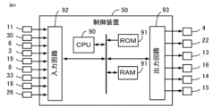
- FIG. 2 is a hardware configuration diagram of a control device according to the first embodiment.
- 4 is a time chart for explaining an angle information detection process according to the first embodiment.
- 5 is a diagram for explaining correction values stored in a storage device according to the first embodiment;
- FIG. 5 is a time chart for illustrating a process for calculating a crank acceleration and an angular acceleration according to the first embodiment.
- 5 is a diagram for explaining a process of a first ideal angular velocity calculation unit according to the first embodiment.
- FIG. 5 is a diagram for explaining the estimation principle of an external load torque according to the first embodiment.
- FIG. 5 is a diagram for explaining the estimation principle of an external load torque according to the first embodiment.
- FIG. 5 is a diagram for explaining the estimation principle of an external load torque according to the first embodiment.
- FIG. 5 is a diagram for explaining estimation of an external load torque according to the first embodiment.
- FIG. 10 is a diagram for explaining fluctuations in crank angular velocity when the correction process according to the first embodiment is not performed.
- FIG. 10 is a diagram for explaining fluctuations in crank angular velocity when the correction process according to the first embodiment is not performed.
- FIG. 6 is a diagram for explaining a process of a second ideal angular velocity calculation unit according to the first embodiment.
- FIG. 10A to 10C are diagrams for explaining the behavior of the crank angular velocity when the correction process according to the first embodiment is not performed.
- 5A to 5C are diagrams for explaining the behavior of the crank angular velocity when the correction process according to the first embodiment is performed.
- 5 is a diagram for explaining fluctuations in crank angular velocity when performing correction processing according to the first embodiment.
- FIG. 13 is a diagram for explaining a process of a first ideal angular velocity calculation unit according to the second embodiment.
- FIG. 13 is a diagram for explaining a process of a second ideal angular velocity calculation unit according to the second embodiment.
- FIG. 13 is a diagram for explaining the processing of a correction value changing unit according to the third embodiment.
- FIG. 1 A control device 50 for an internal combustion engine 1 according to a first embodiment (hereinafter simply referred to as the control device 50) will be described with reference to the drawings.
- Figures 1 and 2 are schematic configuration diagrams of the internal combustion engine 1 and the control device 50 according to this embodiment
- Figure 3 is a block diagram of the control device 50 according to this embodiment.
- the internal combustion engine 1 and the control device 50 are mounted on a vehicle, and the internal combustion engine 1 serves as a driving force source for the vehicle (wheels).
- the internal combustion engine 1 has a cylinder 7 that burns a mixture of air and fuel.
- the internal combustion engine 1 has an intake passage 23 that supplies air to the cylinder 7, and an exhaust passage 17 that discharges exhaust gas burned in the cylinder 7.
- the internal combustion engine 1 is a gasoline engine.
- the internal combustion engine 1 has a throttle valve 4 that opens and closes the intake passage 23.
- the throttle valve 4 is an electronically controlled throttle valve that is driven to open and close by an electric motor controlled by a control device 50.
- the throttle valve 4 is provided with a throttle opening sensor 19 that outputs an electric signal according to the opening of the throttle valve 4.
- the intake passage 23 upstream of the throttle valve 4 is provided with an airflow sensor 3 that outputs an electrical signal according to the amount of intake air drawn into the intake passage 23.
- the internal combustion engine 1 is provided with an exhaust gas recirculation device 20.
- the exhaust gas recirculation device 20 has an EGR flow path 21 that recirculates exhaust gas from the exhaust passage 17 to the intake manifold 12, and an EGR valve 22 that opens and closes the EGR flow path 21.
- the intake manifold 12 is the part of the intake passage 23 downstream of the throttle valve 4.
- the EGR valve 22 is an electronically controlled EGR valve that is driven to open and close by an electric motor controlled by the control device 50.
- the exhaust passage 17 is provided with an air-fuel ratio sensor 18 that outputs an electrical signal according to the air-fuel ratio of the exhaust gas in the exhaust passage 17.
- the intake manifold 12 is provided with a gas pressure sensor 8 that outputs an electrical signal corresponding to the pressure inside the intake manifold 12.
- An injector 13 that injects fuel is provided in the downstream portion of the intake manifold 12. The injector 13 may be provided so as to inject fuel directly into the cylinder 7.
- the internal combustion engine 1 is provided with an atmospheric pressure sensor 33 that outputs an electrical signal corresponding to the atmospheric pressure.
- the intake valve 14 is provided with an intake variable valve timing mechanism that varies the valve opening and closing timing.
- the exhaust valve 15 is provided with an exhaust variable valve timing mechanism that varies the valve opening and closing timing.
- the variable valve timing mechanisms 14 and 15 have electric actuators.
- the internal combustion engine 1 has a number of cylinders 7 (three in this example). Each cylinder 7 has a piston 5 inside. The piston 5 of each cylinder 7 is connected to the crankshaft 2 via a connecting rod 9 and a crank 32. The crankshaft 2 is rotationally driven by the reciprocating motion of the piston 5. The combustion gas pressure generated in each cylinder 7 presses against the top surface of the piston 5, and rotates the crankshaft 2 via the connecting rod 9 and the crank 32.
- the crankshaft 2 is connected to a power transmission mechanism that transmits driving force to the wheels.
- the power transmission mechanism is composed of a transmission, a differential gear, etc. Note that a vehicle equipped with the internal combustion engine 1 may be a hybrid vehicle equipped with a motor generator in the power transmission mechanism.
- the internal combustion engine 1 is equipped with a signal plate 10 that rotates integrally with the crankshaft 2.
- the signal plate 10 has multiple teeth at multiple predetermined crank angles.
- the signal plate 10 has teeth arranged at 10 degree intervals.
- the teeth of the signal plate 10 have missing teeth.
- the internal combustion engine 1 is equipped with a first crank angle sensor 11 that is fixed to the engine block 24 and detects the teeth of the signal plate 10.
- the internal combustion engine 1 is equipped with a camshaft 29 connected to the crankshaft 2 by a chain 28.
- the camshaft 29 drives the intake valve 14 and the exhaust valve 15 to open and close.
- the camshaft 29 rotates once while the crankshaft 2 rotates twice.
- the internal combustion engine 1 is equipped with a cam signal plate 31 that rotates together with the camshaft 29.
- the cam signal plate 31 has a number of teeth at a number of predetermined camshaft angles.
- the internal combustion engine 1 is equipped with a cam angle sensor 30 that is fixed to the engine block 24 and detects the teeth of the cam signal plate 31.
- the control device 50 detects the crank angle based on the top dead center of each piston 5 and determines the stroke of each cylinder 7 based on two types of output signals from the first crank angle sensor 11 and the cam angle sensor 30.
- the internal combustion engine 1 is a four-stroke engine with an intake stroke, a compression stroke, a combustion stroke, and an exhaust stroke.
- the internal combustion engine 1 is equipped with a flywheel 27 that rotates integrally with the crankshaft 2.
- the outer periphery of the flywheel 27 is the ring gear 25, which has multiple teeth at multiple predetermined crank angles.
- the teeth of the ring gear 25 are arranged at equal angular intervals in the circumferential direction. In this example, 60 teeth are provided at intervals of 6 degrees.
- the teeth of the ring gear 25 are not missing teeth.
- the internal combustion engine 1 is equipped with a second crank angle sensor 6 that is fixed to the engine block 24 and detects the teeth of the ring gear 25.
- the second crank angle sensor 6 is arranged radially outside the ring gear 25, facing the ring gear 25 with a gap between them.
- the side of the flywheel 27 opposite the crankshaft 2 is connected to a power transmission mechanism. Therefore, the output torque of the internal combustion engine 1 is transmitted to the wheels through the flywheel 27.
- the first crank angle sensor 11, cam angle sensor 30, and second crank angle sensor 6 output an electrical signal according to the change in distance between each sensor and the teeth due to the rotation of the crankshaft 2.
- the output signal of each angle sensor 11, 30, 6 is a square wave that turns on and off depending on whether the sensor is close to the teeth or far away.
- Each angle sensor 11, 30, 6 is, for example, an electromagnetic pickup type sensor.
- the flywheel 27 (ring gear 25) has a greater number of teeth than the signal plate 10 and is free of any missing teeth, allowing for high-resolution angle detection.
- the flywheel 27 also has a greater mass than the signal plate 10, suppressing high-frequency vibrations, allowing for high-precision angle detection.
- the second crank angle sensor 6 corresponds to the "specific crank angle sensor” in this application
- the flywheel 27 corresponds to the “rotating member” in this application
- the teeth of the ring gear 25 provided on the flywheel 27 correspond to the "detected part” in this application
- the engine block 24 corresponds to the "non-rotating member” in this application.
- the control device 50 is a control device that controls the internal combustion engine 1.
- the control device 50 includes control units such as an intake pipe gas pressure detection unit 51, an angle information detection unit 52, an angle information correction unit 53, an average interval setting unit 54, a one-revolution time detection unit 55, a first shaft torque estimation unit 56, a first ideal angular velocity calculation unit 57, a detection interval angular velocity calculation unit 58, an ideal average value calculation unit 59, a detection average value calculation unit 60, an external load torque estimation unit 61, a second shaft torque estimation unit 62, a second ideal angular velocity calculation unit 63, a correction value change unit 64, and an abnormality determination unit 65.
- control units such as an intake pipe gas pressure detection unit 51, an angle information detection unit 52, an angle information correction unit 53, an average interval setting unit 54, a one-revolution time detection unit 55, a first shaft torque estimation unit 56, a first ideal angular velocity calculation unit 57, a detection interval angular velocity calculation unit 58, an ideal average
- control device 50 includes, as processing circuits, a calculation processing device 90 (computer) such as a CPU (Central Processing Unit), a memory device 91 connected to the calculation processing device 90 via a signal line such as a bus, an input circuit 92 that inputs external signals to the calculation processing device 90, and an output circuit 93 that outputs signals from the calculation processing device 90 to the outside.
- a calculation processing device 90 computer
- CPU Central Processing Unit
- memory device 91 connected to the calculation processing device 90 via a signal line such as a bus
- input circuit 92 that inputs external signals to the calculation processing device 90
- output circuit 93 that outputs signals from the calculation processing device 90 to the outside.
- the arithmetic processing device 90 may be an ASIC (Application Specific Integrated Circuit), an IC (Integrated Circuit), a DSP (Digital Signal Processor), an FPGA (Field Programmable Gate Array), various logic circuits, and various signal processing circuits.
- ASIC Application Specific Integrated Circuit
- IC Integrated Circuit
- DSP Digital Signal Processor
- FPGA Field Programmable Gate Array
- various logic circuits and various signal processing circuits.
- multiple arithmetic processing devices 90 of the same type or different types may be provided, and each process may be shared and executed.
- the memory device 91 includes volatile and non-volatile memory devices such as RAM (Random Access Memory), ROM (Read Only Memory), and EEPROM (Electrically Erasable Programmable ROM).
- the input circuit 92 is connected to various sensors and switches and includes A/D converters and the like that input the output signals of these sensors and switches to the arithmetic processing device 90.
- the output circuit 93 is connected to electrical loads and includes drive circuits and the like that output control signals from the arithmetic processing device 90 to these electrical loads.
- control units 51 to 65 of the control device 50 are realized by the arithmetic processing device 90 executing software (programs) stored in a storage device 91 such as a ROM or EEPROM, and working in cooperation with other hardware of the control device 50 such as the storage device 91, input circuit 92, and output circuit 93.
- the setting data of the moment of inertia Icrk and judgment values used by the control units 51 to 65 are stored in the storage device 91 such as a ROM or EEPROM.
- the data of the calculated values and detected values of the correction value Kc, angle interval ⁇ d, time interval ⁇ Td, first shaft torque estimate value Tcrke1, first ideal interval angular velocity ⁇ id1, detection interval angular velocity ⁇ sd, and external load torque Tload calculated by the control units 51 to 65 are stored in a rewritable storage device 91 such as a RAM.
- the input circuit 92 is connected to the first crank angle sensor 11, the cam angle sensor 30, the second crank angle sensor 6, the airflow sensor 3, the throttle opening sensor 19, the gas pressure sensor 8, the atmospheric pressure sensor 33, the air-fuel ratio sensor 18, and the accelerator position sensor 26.
- the output circuit 93 is connected to the throttle valve 4 (electric motor), the EGR valve 22 (electric motor), the injector 13, the ignition coil 16, the intake variable valve timing mechanism 14, and the exhaust variable valve timing mechanism 15.
- various sensors, switches, actuators, etc. are connected to the control device 50.
- the control device 50 detects the operating state of the internal combustion engine 1, such as the intake air volume, the pressure in the intake manifold, the atmospheric pressure, the air-fuel ratio, and the accelerator opening, based on the output signals of the various sensors.
- the control device 50 calculates the fuel injection amount, ignition timing, etc. based on the output signals of various sensors inputted, and drives and controls the injector 13 and the ignition coil 16, etc.
- the control device 50 calculates the output torque of the internal combustion engine 1 requested by the driver based on the output signal of the accelerator position sensor 26, etc., and controls the throttle valve 4, etc. so that the intake air volume realizes the requested output torque.
- the control device 50 calculates the target throttle opening, and drives and controls the electric motor of the throttle valve 4 so that the throttle opening detected based on the output signal of the throttle opening sensor 19 approaches the target throttle opening.
- the control device 50 also calculates the target opening of the EGR valve 22 based on the output signals of various sensors inputted, and drives and controls the electric motor of the EGR valve 22.
- the control device 50 calculates the target opening and closing timing of the intake valve and the target opening and closing timing of the exhaust valve based on the output signals of various sensors input, and controls the operation of the intake and exhaust variable valve timing mechanisms 14, 15 based on each target opening and closing timing.
- the intake pipe gas pressure detection unit 51 detects the gas pressure Pind in the intake pipe based on the output signal of the gas pressure sensor 8. The gas pressure Pind in the intake pipe is detected at every predetermined detection period.
- the angle information detection unit 52 detects the crank angle ⁇ d based on the output signal of the second crank angle sensor 6 designated as the specific crank angle sensor, and detects the detection time Td at which the crank angle ⁇ d is detected. Then, the angle information detection unit 52 calculates an angle interval ⁇ d corresponding to an angle section Sd between the detected angles ⁇ d based on the detected crank angle ⁇ d, and calculates a time interval ⁇ Td corresponding to the angle section Sd based on the detection time Td.
- the angle information detection unit 52 is configured to determine the crank angle ⁇ d when the falling edge (or rising edge) of the output signal (rectangular wave) of the second crank angle sensor 6 is detected.
- the angle information detection unit 52 determines a base falling edge, which is a falling edge corresponding to a base angle (for example, 0 degrees, which is the top dead center of the piston 5 of the first cylinder 7), and determines the crank angle ⁇ d corresponding to the number n of the falling edge counted up from the base falling edge (hereinafter referred to as angle identification number n).
- angle identification number n For example, when the angle information detection unit 52 detects a base falling edge, it sets the crank angle ⁇ d to the base angle (for example, 0 degrees) and sets the angle identification number n to 1.
- each time the angle information detection unit 52 detects a falling edge it increases the crank angle ⁇ d by a preset angle interval ⁇ d (6 degrees in this example) and increases the angle identification number n by one.
- the angle information detection unit 52 may be configured to read out the crank angle ⁇ d corresponding to the current angle identification number n using an angle table in which the relationship between the angle identification number n and the crank angle ⁇ d is preset.
- the angle information detection unit 52 associates the crank angle ⁇ d (detected angle ⁇ d) with the angle identification number n. After the maximum number (60 in this example), the angle identification number n returns to 1.
- the detection time Td and detection angle ⁇ d in which the missing tooth portion is complemented with information before and after the missing tooth portion may be used, or the detection time Td and detection angle ⁇ d in which the missing tooth portion is not complemented may be used as is. If the missing tooth portion is not complemented, the angle interval ⁇ d corresponding to the missing tooth portion is used in each calculation.
- the angle information detection unit 52 determines the base point falling edge of the second crank angle sensor 6 by referring to the reference crank angle ⁇ r detected based on the first crank angle sensor 11 and the cam angle sensor 30, which will be described later. For example, the angle information detection unit 52 determines that the falling edge of the reference crank angle ⁇ r at the time when the falling edge of the second crank angle sensor 6 is detected is closest to the base point angle, as the base point falling edge.
- the angle information detection unit 52 also refers to the stroke of each cylinder 7 determined based on the first crank angle sensor 11 and the cam angle sensor 30 to determine the stroke of each cylinder 7 corresponding to the crank angle ⁇ d.
- the angle information detection unit 52 detects the detection time Td when it detects the falling edge of the output signal (rectangular wave) of the second crank angle sensor 6, and associates the detection time Td with the angle identification number n. Specifically, the angle information detection unit 52 detects the detection time Td using a timer function provided in the calculation processing device 90.
- the angle information detection unit 52 when the angle information detection unit 52 detects a falling edge, it sets the angle interval between the detection angle ⁇ d(n) corresponding to the current angle identification number (n) and the detection angle ⁇ d(n-1) corresponding to the previous angle identification number (n-1) to the angle interval Sd(n) corresponding to the current angle identification number (n).
- the angle information detection unit 52 when the angle information detection unit 52 detects a falling edge, it calculates the deviation between the detection angle ⁇ d(n) corresponding to the current angle identification number (n) and the detection angle ⁇ d(n-1) corresponding to the previous angle identification number (n-1), and sets this as the angle interval ⁇ d(n) corresponding to the current angle identification number (n) (current angle interval Sd(n)).
- the angular intervals of the teeth of the ring gear 25 are all equal, so the angle information detection unit 52 sets the angular intervals ⁇ d of all angle identification numbers n to a preset angle (6 degrees in this example).
- the angle information detection unit 52 when the angle information detection unit 52 detects a falling edge, it calculates the deviation between the detection time Td(n) corresponding to the current angle identification number (n) and the detection time Td(n-1) corresponding to the previous angle identification number (n-1), and sets this as the time interval ⁇ Td(n) corresponding to the current angle identification number (n) (current angle interval Sd(n)).
- the angle information detection unit 52 detects the reference crank angle ⁇ r based on the top dead center of the piston 5 of the first cylinder 7 based on two types of output signals from the first crank angle sensor 11 and the cam angle sensor 30, and determines the stroke of each cylinder 7. For example, the angle information detection unit 52 determines the falling edge immediately after the missing tooth part of the signal plate 10 from the time interval of the falling edges of the output signal (rectangular wave) of the first crank angle sensor 11. Then, the angle information detection unit 52 determines the correspondence between each falling edge based on the falling edge immediately after the missing tooth part and the reference crank angle ⁇ r based on the top dead center, and calculates the reference crank angle ⁇ r based on the top dead center when each falling edge is detected. In addition, the angle information detection unit 52 determines the stroke of each cylinder 7 from the relationship between the position of the missing tooth part in the output signal (rectangular wave) of the first crank angle sensor 11 and the output signal (rectangular wave) of the cam angle sensor 30.
- the angle information correction unit 53 corrects each angle interval ⁇ d or each time interval ⁇ Td of the angle interval Sd by a correction value Kc provided for each angle interval Sd.
- the angle information correction unit 53 provides one correction value Kc(n) for each angle interval Sd(n) of each angle identification number n.
- each correction value Kc is associated with each angle identification number n and stored in a rewritable storage device 91 such as a RAM of the control device 50.
- the angle information correction unit 53 multiplies the time interval ⁇ Td(n) corresponding to the current angle identification number (n) by the correction value Kc(n) corresponding to the current angle identification number (n) to calculate the corrected time interval ⁇ Tdc(n) corresponding to the current angle identification number (n).
- the angle information correction unit 53 divides the angle interval ⁇ d(n) corresponding to the current angle identification number (n) by the correction value Kc(n) corresponding to the current angle identification number (n) to calculate the corrected angle interval ⁇ dc(n) corresponding to the current angle identification number (n).
- the angle information correction unit 53 may be configured to correct the crank angular velocity ⁇ d(n) calculated based on the angle interval ⁇ d(n) and the time interval ⁇ Td(n) before correction with the correction value Kc(n).
- the time interval ⁇ Td is corrected by the correction value Kc.
- the angle interval ⁇ d that has not been corrected by the correction value Kc is also referred to as the angle interval ⁇ dc after correction processing.
- crank angular velocity ⁇ d which is the time rate of change of the crank angle ⁇ d
- crank angular acceleration ⁇ d which is the time rate of change of the crank angular velocity ⁇ d
- the angle information detection unit 52 calculates the crank angular velocity ⁇ d(n) corresponding to the angle interval Sd(n) to be processed based on the corrected angle interval ⁇ dc(n) and time interval ⁇ Tdc(n) corresponding to the angle interval Sd(n) to be processed. Specifically, as shown in equation (4), the angle information detection unit 52 calculates the crank angular velocity ⁇ d(n) by dividing the corrected angle interval ⁇ dc(n) corresponding to the angle interval Sd(n) to be processed by the corrected time interval ⁇ Tdc(n).
- the angle information detection unit 52 calculates the crank angular acceleration ⁇ d(n) corresponding to the detection angle ⁇ d(n) to be processed based on the crank angular velocity ⁇ d(n) corresponding to one angle section Sd(n) immediately before the detection angle ⁇ d(n) to be processed and the time interval after correction ⁇ Tdc(n), and the crank angular velocity ⁇ d(n+1) corresponding to one angle section Sd(n+1) immediately after the detection angle ⁇ d(n) to be processed and the time interval after correction ⁇ Tdc(n+1).
- the angle information detection unit 52 calculates the crank angular acceleration ⁇ d(n) by dividing the subtracted value obtained by subtracting the immediately preceding crank angular velocity ⁇ d(n) from the immediately following crank angular velocity ⁇ d(n+1) by the average value of the immediately following time interval after correction ⁇ Tdc(n+1) and the immediately preceding time interval after correction ⁇ Tdc(n).
- crank angular velocity ⁇ d(n) and the crank angular acceleration ⁇ d(n) are used to estimate the combustion state and control various known internal combustion engines.
- the averaging interval setting unit 54 sets an averaging processing angle interval Save within a one-rotation angle interval S360 that corresponds to one rotation of the crankshaft.
- the average interval setting unit 54 sets the angle interval that overlaps between the first one-rotation angle interval S360_1 and the second one-rotation angle interval S360_2 described below as the average processing angle interval Save.
- the average interval setting unit 54 sets the average processing angle interval Save in correspondence with the compression stroke of each cylinder.
- the average interval setting unit 54 sets the average processing angle interval Save to the compression stroke of each cylinder.
- the average processing angle interval Save is set to 180 degrees.
- the one-revolution time detection unit 55 detects a one-revolution time interval ⁇ T360, which is the time interval of the one-revolution angular interval S360 that the crankshaft takes to rotate once, based on the output signal of the second crank angle sensor 6, and calculates an average detected angular velocity ⁇ saved, which is the average angular velocity of the average processing angle interval Save set within the range of the one-revolution angular interval S360, based on the detected value ⁇ T360 of the one-revolution time interval.
- ⁇ T360 is the time interval of the one-revolution angular interval S360 that the crankshaft takes to rotate once
- the one-rotation time detection unit 55 detects a first one-rotation time interval ⁇ T360_1 and a second one-rotation time interval ⁇ T360_2 for a first one-rotation angle interval S360_1 and a second one-rotation angle interval S360_2 that overlap with each other but are offset in angle.
- the one-rotation time detection unit 55 then calculates a time interval ⁇ Tsave of the average processing angle interval based on the average value of the first one-rotation time interval ⁇ T360_1 and the second one-rotation time interval ⁇ T360_2, and calculates an average detected angular velocity ⁇ saved based on the time interval ⁇ Tsave of the average processing angle interval.
- the average processing angle interval Save is set to 180 degrees.
- the first one rotation angle interval S360_1 is set to an angle interval from an angle 180 degrees retarded from the start angle of the average processing angle interval Save to the end angle of the average processing angle interval Save.
- the second one rotation angle interval S360_2 is set to an angle interval from the start angle of the average processing angle interval Save to an angle 180 degrees advanced from the end angle of the average processing angle interval Save. The process of calculating the average detected angular velocity ⁇ saved is performed for each average processing angle interval Save.
- the one-rotation time detection unit 55 calculates the average detected angular velocity ⁇ saved by using the following equation.
- the average processing angle interval Save may be set to any angle within 360 degrees.
- the average processing angle interval Save may be set to 360 degrees.
- the first one-rotation angle interval S360_1 and the second one-rotation angle interval S360_2 are the same, so the average detected angular velocity ⁇ saved can be calculated based on the one-rotation time interval ⁇ T360 of one one-rotation angle interval S360.
- the first axial torque estimation unit 56 estimates a first axial torque estimate value Tcrke1(n), which is the axial torque of the crankshaft due to the gas pressure in the cylinder and the reciprocating motion of the piston, for each angle interval Sd(n) using a physical model equation of the crank mechanism based on the detected value Pind of the gas pressure in the intake pipe and the detected angle ⁇ d.
- the first axial torque estimation unit 56 calculates the gas pressure torque Tgas generated by the gas pressure Pcyl in the cylinder and the inertia torque Tin generated by the reciprocating motion of the piston, and calculates the first axial torque estimate Tcrke1 by summing the gas pressure torque Tgas and the inertia torque Tin.
- the first shaft torque estimation unit 56 uses a physical model equation to calculate the gas pressure torque generated by the gas pressure in the cylinder, and calculates the gas pressure torque Tgas generated by the gas pressure Pcyl in the cylinder based on the detected value Pind of the gas pressure in the intake pipe.
- the first shaft torque estimation unit 56 calculates the gas pressure torque Tgas generated by the gas pressure in the cylinder when it is assumed that the internal combustion engine is in an uncombusted state where no combustion is occurring.
- the first axial torque estimation unit 56 uses an equation for calculating gas pressure using a polytropic change to calculate the gas pressure in the cylinder i for a cylinder i whose intake valve and exhaust valve are closed, and calculates the gas pressure Pcyl_i in the cylinder based on the detection value Pind of the gas pressure in the intake pipe and the crank angle ⁇ d.
- the first axial torque estimation unit 56 calculates the gas pressure Pcyl_i in the cylinder i for a cylinder i whose intake valve is open and whose exhaust valve is closed based on the detection value Pind of the gas pressure in the intake pipe, and calculates the gas pressure Pcyl_i in the cylinder i for a cylinder i whose exhaust valve is open based on the gas pressure Pex in the exhaust pipe.
- Nply is a polytropic index
- Vcyl0 is the cylinder volume when the intake valve is closed, and a preset value may be used, or it may be changed according to the intake valve closing timing by the intake variable valve timing mechanism 14.
- Vcly_ ⁇ _i is the cylinder volume of each cylinder i at the crank angle ⁇ d_i of each cylinder i, and is a function of the crank angle ⁇ d_i of each cylinder i.
- Vcyltop is the cylinder volume when the piston is located at the top dead center
- Sp is the projected area of the top surface of the piston
- r is the crank length
- L is the connecting rod length
- ⁇ _i is the angle of the connecting rod of each cylinder i.
- crank angle ⁇ d_i of each cylinder i used in the calculation of the trigonometric function a crank angle obtained by shifting the crank angle ⁇ d so that the top dead center of the compression stroke is 0 degrees for each cylinder i is used.
- the detected value Pind of the gas pressure in the intake pipe may be a value obtained by averaging, such as the average value of the stroke period, or the detected value when the intake valve is closed.
- the detected value of the atmospheric pressure or a predetermined value may be used for the gas pressure Pex in the exhaust pipe.
- the first shaft torque estimation unit 56 calculates the gas pressure torque Tgas based on the gas pressure Pcyl_i in each cylinder i and the crank angle ⁇ d_i, using the following equation for converting gas pressure into torque.
- Pcase is the internal pressure in the crankcase (piston back pressure) and may be set to a predetermined value or may be changed according to the detected gas pressure value Pind in the intake pipe, atmospheric pressure, etc.
- R_i is a conversion coefficient that converts the force generated in the piston of each cylinder i into torque about the crankshaft and is a function of the crank angle ⁇ d_i of each cylinder i.
- map data in which the relationship between the crank angle ⁇ d and the conversion coefficient R is preset may be used. Note that in the case of an offset crank, the offset may be taken into account when calculating the conversion coefficient R_i.
- the first shaft torque estimation unit 56 uses a physical model equation that calculates the inertia torque generated by the reciprocating motion of the piston at each crank angle ⁇ d, and calculates the inertia torque Tin generated by the reciprocating motion of the piston based on the crank angular velocity ⁇ d.
- the first axial torque estimation unit 56 uses the following equation, which converts the piston acceleration and the piston inertia force into torque, to calculate the inertia torque Tin generated by the reciprocating motion of the piston of each cylinder i based on the crank angular velocity ⁇ d and the crank angle ⁇ d.
- mp is the mass of the piston
- Ka_i is a coefficient for calculating the acceleration of the piston based on the crank angular velocity ⁇ d, which is a function of the crank angle ⁇ d_i of each cylinder i.
- the acceleration calculation coefficient Ka_i of each cylinder i may be set based on the third equation of equation (9).
- the third equation of equation (9) is an approximation, but an exact value may be calculated.
- map data in which the relationship between the crank angle ⁇ d and the acceleration calculation coefficient Ka is preset may be used.
- an offset may be taken into account in the calculation of the acceleration calculation coefficient Ka_i of each cylinder i.
- the conversion coefficient R_i of each cylinder i is the same as equation (8).
- an inertia torque generated by the inertia of the connecting rod, etc. may be added to the inertia torque Tin.
- the first shaft torque estimating unit 56 sums up the gas pressure torque Tgas and the inertia torque Tin calculated at each crank angle ⁇ d to calculate an estimated value Tcrke1 of the first shaft torque for each crank angle ⁇ d.
- the first shaft torque estimator 56 calculates the first shaft torque estimate Tcrke1(n) of each angle section Sd(n) based on the first shaft torque estimate Tcrke1 of each crank angle ⁇ d. For example, the first shaft torque estimate Tcrke1(n) corresponding to the center position of each angle section Sd(n) is calculated.
- the first shaft torque estimator 56 calculates the average value of the first shaft torque estimate Tcrke1( ⁇ d(n-1)) of the start crank angle ⁇ d(n-1) of each angle section Sd(n) and the first shaft torque estimate Tcrke1( ⁇ d(n)) of the end crank angle ⁇ d(n) of each angle section Sd(n) as the first shaft torque estimate Tcrke1(n) of each angle section Sd(n).
- crank angle ⁇ d used to calculate the first shaft torque estimate value Tcrke1 may be set to the crank angle ⁇ d corresponding to the center position of each angle interval Sd, and the first shaft torque estimate value Tcrke1 corresponding to the center position of each angle interval Sd may be directly calculated.
- the first ideal angular velocity calculation unit 57 calculates a first ideal section angular velocity ⁇ id1, which is the angular velocity corresponding to each of the angle sections Sd(n) in a first ideal state assuming that there is no fluctuation in the multiple crank angles at which multiple teeth are arranged (hereinafter also referred to as tooth arrangement crank angles) and that there is no external load torque Tload, based on the first shaft torque estimate value Tcrke1(n) for each of the angle sections Sd(n) and the moment of inertia Icrk of the crankshaft system.
- the first shaft torque estimate Tcrke1 is calculated using a physical model equation for the crank mechanism, and therefore is the shaft torque in the first ideal state, which assumes that there is no variation in the tooth arrangement crank angle and no external load torque Tload.
- the first ideal interval angular velocity ⁇ id1 is calculated based on the first shaft torque estimate Tcrke1, and therefore is the interval angular velocity in the first ideal state.
- the first ideal angular velocity calculation unit 57 calculates the first ideal interval angular acceleration ⁇ id1(n), which is the angular acceleration of the first ideal state corresponding to each angle interval Sd(n), based on the estimated value Tcrke1(n) of the first shaft torque for each angle interval Sd(n) and the moment of inertia Icrk of the crankshaft system.
- the first ideal angular velocity calculation unit 57 sets the first ideal section angular velocity ⁇ id1(Q-1) of the angle section Sd(Q-1) immediately before the average processing angle section Save to the second ideal section angular velocity ⁇ id2(Q-1) calculated in the last angle section Sd(Q-1) of the previous average processing angle section Save, which corresponds to the angle section Sd(Q-1) immediately before the average processing angle section Save.
- the first ideal angular velocity calculation unit 57 may set the first ideal section angular velocity ⁇ id1(Q-1) of the angle section Sd(Q-1) immediately before the average processing angle section Save to the average value of the detection section angular velocities ⁇ sd of the angle section Sd(Q-1) immediately before the average processing angle section Save and the multiple angle sections Sd before and after it.
- the first ideal angular velocity calculation unit 57 integrates the first ideal section angular acceleration ⁇ id1(n) in the averaging processing angle section Save to calculate the first ideal section angular velocity ⁇ id1(n), which is the angular velocity of the first ideal state corresponding to each of the angle sections Sd(n).
- the first ideal angular velocity calculation unit 57 calculates the first ideal section angular velocity ⁇ id1 using the following formula.
- Q is an angle identification number corresponding to the first angle section of the averaging processing angle section Save, and the angle section corresponding to the start angle is set to the angle section immediately after the start angle of the averaging processing angle section Save.
- angle section corresponding to the start angle may be set to the angle section immediately before the start angle.
- R is an angle identification number corresponding to the last angle section of the averaging processing angle section Save. This calculation process is performed for each angle section Sd(n) of the averaging processing angle section Save.
- the detection section angular velocity calculation unit 58 calculates, for each angle section Sd, a detection section angular velocity ⁇ sd that is the angular velocity corresponding to the angle section Sd, based on the time interval ⁇ Tdc and the angle interval after correction processing using the correction value Kc.
- the detection section angular velocity calculation unit 58 calculates the detection section angular velocity ⁇ sd(n) corresponding to each of the angle sections Sd(n) using the following equation.
- the ideal average value calculation unit 59 calculates the average value ⁇ id1_ave of the first ideal interval angular velocity ⁇ id1 in the averaging processing angular interval Save.
- the detection average value calculation unit 60 calculates the average value ⁇ sd_ave of the detection section angular velocity ⁇ sd in the averaging processing angular section Save.
- the average detected angular velocity ⁇ saved calculated by the one-rotation time detection unit 55 may be used as the average value ⁇ sd_ave of the detected section angular velocity ⁇ sd.
- the external load torque estimating unit 61 estimates an external load torque Tload, which is a torque applied to the crankshaft from outside the internal combustion engine, based on the difference between the average value ⁇ sd_ave of the detection section angular velocity and the average value ⁇ id1_ave of the first ideal section angular velocity.
- the external load torque Tload causes a difference between the first ideal section angular velocity ⁇ id1 and the detection section angular velocity ⁇ sd.
- the detection section angular velocity ⁇ sd fluctuates due to variations in the angle of the teeth of the signal plate 10 and setting errors in the correction value Kc, etc. Therefore, the instantaneous difference between the first ideal section angular velocity ⁇ id1 and the detection section angular velocity ⁇ sd is greatly affected by the fluctuations in the detection section angular velocity ⁇ sd, and the external load torque Tload cannot be estimated accurately.
- the difference between the average detection section angular velocity ⁇ sd_ave and the average first ideal section angular velocity ⁇ id1_ave is used, so the influence of the fluctuations in the detection section angular velocity ⁇ sd is smoothed, and the external load torque Tload can be estimated accurately.
- the external load torque estimator 61 subtracts the average value ⁇ id1_ave of the first ideal section angular velocities from the average value ⁇ sd_ave of the detection section angular velocities, multiplies the result by 2, divides the result by the time interval ⁇ Tsave of the averaging processing angle section, and multiplies the result by the moment of inertia Icrk of the crankshaft system to calculate the external load torque Tload.
- the second ideal section angular velocity ⁇ id2(Q-1) calculated in the last angle section Sd(Q-1) of the previous average processing angle section Save which corresponds to the angle section Sd(Q-1) immediately before the average processing angle section Save, is set as the first ideal section angular velocity ⁇ id1(Q-1) of the angle section Sd(Q-1) immediately before the average processing angle section Save, so that it generally matches the behavior of the detection section angular velocity ⁇ sd.
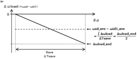
- the external load torque Tload is constant in the average processing angle section Save, and that the crank angular acceleration ⁇ load generated by the external load torque is constant. Therefore, as shown in FIG.
- the difference between the average value ⁇ sd_ave of the detection section angular velocity and the average value ⁇ id1_ave of the first ideal section angular velocity corresponds to the average value of the speed fluctuation amount ⁇ load in the averaging processing angle section Save.
- the average value of the speed fluctuation amount ⁇ load is a value obtained by dividing the speed fluctuation ⁇ load_end of the end angle of the averaging processing angle section Save by 2.
- the speed fluctuation ⁇ load_end of the end angle of the averaging processing angle section Save is a value obtained by multiplying the crank angular acceleration ⁇ load due to the external load torque by the averaging processing angle section Save.
- crank angular acceleration ⁇ load due to the external load torque is a value obtained by dividing the external load torque Tload by the moment of inertia Icrk.
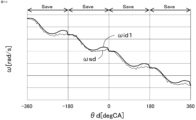
- Figure 10 shows a time chart of the test data. Note that the correction value Kc is set to 1, and the detection section angular velocity ⁇ sd fluctuates due to variation in the angle of the teeth of the signal plate 10.
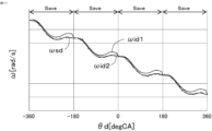
- FIG. 11 shows a time chart in which the second ideal interval angular velocity ⁇ id2 calculated using the accurately estimated external load torque Tload is overlaid on FIG. 10.
- the second ideal interval angular velocity ⁇ id2 overlaps with the detection interval angular velocity ⁇ sd, and it can be seen that the correction value Kc can be changed with high precision by comparing the second ideal interval angular velocity ⁇ id2 with the detection interval angular velocity ⁇ sd.
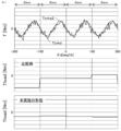
- the middle shows a time chart of a comparative example of the external load torque Tload calculated by multiplying the real shaft torque Tcrkd near the top dead center by the inertia torque Tin
- the bottom shows a time chart of the external load torque Tload according to this embodiment.
- the amount of fluctuation in the detection section angular velocity ⁇ sd near the top dead center differs for each average processing angle section Save
- the external load torque Tload fluctuates greatly for each average processing angle section Save.
- the effect of the fluctuation in the detection section angular velocity ⁇ sd during the average processing angle section Save is smoothed, so the amount of fluctuation in the external load torque Tload for each average processing angle section Save is small, and the external load torque Tload can be estimated with high accuracy.
- the external load torque estimation unit 61 estimates the external load torque Tload when the internal combustion engine is in an uncombusted state where no combustion is occurring (when the first condition is met). On the other hand, the external load torque estimation unit 61 does not estimate the external load torque Tload when the internal combustion engine is in a combusted state where combustion is occurring (when the first condition is not met).
- the uncombusted state includes a fuel cut state where the supply of fuel is stopped.
- the external load torque estimation unit 61 may calculate the final external load torque Tload by performing a smoothing process on the external load torque Tload estimated corresponding to the current and past average processing angle intervals Save.
- the rate of change of the external load torque Tload is slow, so by performing smoothing processing on multiple average processing angle intervals Save, the calculation accuracy of the external load torque Tload can be further improved.
- smoothing processes include moving average processing, weighted average processing, and low-pass filter processing such as first-order lag.
- Fig. 13 shows the behavior of the crank angular velocity ⁇ dcmp without correction processing calculated based on the angle interval ⁇ d and the time interval ⁇ Td that are not corrected by the correction value Kc, and the high-precision crank angular velocity ⁇ * detected by a high-precision rotation sensor provided for measurement, when the tooth arrangement crank angle varies.
- the crank angular velocity ⁇ dcmp without correction processing varies with respect to the high-precision crank angular velocity ⁇ * for measurement.
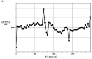
- FIG. 14 shows the angular velocity ratio at each crank angle, obtained by dividing the uncorrected crank angular velocity ⁇ dcmp by the high-precision crank angular velocity ⁇ * used for measurement.
- the angular velocity ratio is greater than 1, the actual angular interval is shorter than the specified angular interval (6 degrees), and when it is less than 1, the actual angular interval is longer than the specified angular interval (6 degrees). Therefore, unless the correction value Kc is appropriately changed and correction is performed using the correction value Kc to cancel out the fluctuations in the tooth arrangement crank angle, high-frequency components will be superimposed on the calculated crank angular velocity ⁇ d and crank angular acceleration ⁇ d, deteriorating the accuracy of internal combustion engine control, such as the estimation of the combustion state and combustion control.
- the process for appropriately changing the correction value Kc is described below.
- the second shaft torque estimation unit 62 adds the external load torque Tload to the estimated value Tcrke1(n) of the first shaft torque in each angle interval Sd(n) to calculate an estimated value Tcrke2(n) of the second shaft torque in each angle interval Sd(n).
- the second ideal angular velocity calculation unit 63 calculates a second ideal section angular velocity ⁇ id2, which is the angular velocity corresponding to each of the angle sections Sd(n) in a second ideal state assuming that there is no fluctuation in the multiple crank angles at which multiple teeth are arranged (hereinafter also referred to as tooth arrangement crank angles), based on the second shaft torque estimate value Tcrke2(n) for each of the angle sections Sd(n) and the moment of inertia Icrk of the crankshaft system.
- the second shaft torque estimate Tcrke2 is calculated by adding the external load torque Tload to the first shaft torque estimate Tcrk1 calculated using the physical model equation of the crank mechanism, and is therefore the shaft torque in the second ideal state assuming that there is no variation in the tooth arrangement crank angle.
- the second ideal interval angular velocity ⁇ id2 is calculated based on the second shaft torque estimate Tcrke2, and is therefore the interval angular velocity in the second ideal state.
- the second ideal angular velocity calculation unit 63 changes the correction value Kc(n) for each angle section Sd(n) so that the average value ⁇ sd_ave of the detection section angular velocity ⁇ sd in the average processing angle section Save does not deviate from the average detected angular velocity ⁇ saved, and matches the average value ⁇ id2_ave of the second ideal section angular velocity ⁇ id2 in the average processing angle section Save to the average detected angular velocity ⁇ saved.
- the second ideal angular velocity calculation unit 63 calculates the second ideal section angular acceleration ⁇ id2(n) which is the angular acceleration in the second ideal state corresponding to each of the angle sections Sd(n) based on the estimated value Tcrke2(n) of the second shaft torque in each of the angle sections Sd(n) and the moment of inertia Icrk of the crankshaft system, and integrates the second ideal section angular acceleration ⁇ id2(n) to calculate the provisional second ideal section angular velocity ⁇ id2tmp(n) which is the angular velocity in the second ideal state corresponding to each of the angle sections Sd(n).
- the second ideal angular velocity calculation unit 63 calculates the provisional second ideal section angular velocity ⁇ id2tmp using the following equation. This calculation process is performed for each angle section Sd(n) of the averaging processing angle section Save.
- the second ideal angular velocity calculation unit 63 calculates an average value ⁇ id2tmp_ave of the provisional second ideal section angular velocities ⁇ id2tmp in the averaging processing angle section Save, where Q is the angle identification number corresponding to the first angle section of the averaging processing angle section Save, and R is the angle identification number corresponding to the last angle section of the averaging processing angle section Save.
- the second ideal angular velocity calculation unit 63 subtracts the average value ⁇ id2tmp_ave of the provisional second ideal section angular velocity from the provisional second ideal section angular velocity ⁇ id2tmp and adds the average detected angular velocity ⁇ saved to calculate the second ideal section angular velocity ⁇ id2. This calculation process is performed for each angle section Sd(n) of the averaging processing angle section Save.
- This calculation process makes it possible to make the average value ⁇ id2_ave of the second ideal section angular velocity ⁇ id2 in the average processing angle section Save coincide with the average detected angular velocity ⁇ saved. Therefore, as described below, the correction value Kc is changed so that the detected section angular velocity ⁇ sd approaches the second ideal section angular velocity ⁇ id2, so that the correction value Kc can be changed so that the average value ⁇ sd_ave of the detected section angular velocity ⁇ sd in the average processing angle section Save does not deviate from the average detected angular velocity ⁇ saved.
- Figure 16 shows the control behavior when the provisional second ideal interval angular velocity ⁇ id2tmp is set as the second ideal interval angular velocity ⁇ id2 under the condition of a constant crank angular velocity.
- the average value ⁇ id2_ave of the second ideal interval angular velocity ⁇ id2 deviates from the average detected angular velocity ⁇ saved
- the average value ⁇ sd_ave of the detected interval angular velocity ⁇ sd deviates from the average detected angular velocity ⁇ saved
- Figure 17 shows the control behavior when corrected as in equation (21).
- the average value ⁇ id2_ave of the second ideal section angular velocity ⁇ id2 matches the average detected angular velocity ⁇ saved, so the average value ⁇ sd_ave of the detected section angular velocity ⁇ sd does not deviate from the average detected angular velocity ⁇ saved, the detected section angular velocity ⁇ sd does not shift, and no error occurs.
- the correction value changing unit 64 changes the correction value Kc(n) for each angle interval Sd(n) so that the detection interval angular velocity ⁇ sd(n), which is the angular velocity corresponding to the angle interval calculated from the time interval ⁇ Tdc and the angle interval ⁇ dc after correction processing using the correction value Kc, approaches the second ideal interval angular velocity ⁇ id2(n).
- the second ideal interval angular velocity ⁇ id2 is an interval angular velocity in the second ideal state, so high-frequency components due to fluctuations in the tooth arrangement crank angle are not superimposed.
- the second ideal interval angular velocity ⁇ id2 has good accuracy because it reflects the accurately estimated external load torque Tload. Therefore, by changing the correction value Kc(n) for each angle interval Sd(n) so that the detected interval angular velocity ⁇ sd(n) approaches the second ideal interval angular velocity ⁇ id2(n), the correction value Kc(n) can be appropriately changed to cancel out fluctuations in the tooth arrangement crank angle.
- the correction value change unit 64 increases the correction value Kc(n) when the detection section angular velocity ⁇ sd(n) exceeds the second ideal section angular velocity ⁇ id2(n) for each angle section Sd(n), and decreases the correction value Kc(n) when the detection section angular velocity ⁇ sd(n) falls below the second ideal section angular velocity ⁇ id2(n).
- the correction value changing unit 64 updates the correction value Kc(n) using the following equation: where Klrn is a learning rate, and a value of 1 or less is set.
- the correction value change unit 64 executes the process of changing the correction value Kc(n) for each angle section Sd(n) of the average processing angle section Save collectively each time the process of calculating the second ideal section angular velocity ⁇ id2(n) for each angle section Sd(n) of the average processing angle section Save is completed.
- the correction value change unit 64 changes the correction value Kc when the internal combustion engine is in an uncombusted state where no combustion is occurring (when the first condition is met). On the other hand, the correction value change unit 64 does not change the correction value Kc when the internal combustion engine is in a combusted state where combustion is occurring (when the first condition is not met).
- the uncombusted state includes a fuel cut state where the supply of fuel is stopped.
- the correction value change unit 64 also changes the correction value Kc when the absolute value of the amount of change in the average value of the detection section angular velocity ⁇ sd is equal to or less than the amount of change judgment value (when the second condition is satisfied). On the other hand, the correction value change unit 64 does not change the correction value Kc when the absolute value of the amount of change is greater than the amount of change judgment value (when the second condition is not satisfied).
- the average value of the detection section angular velocity ⁇ sd is set to, for example, the average value of an averaging period such as the average processing angle section Save or the stroke period.
- the correction value change unit 64 changes the correction value Kc when the operating amount of the brake mechanism of a vehicle equipped with an internal combustion engine is equal to or less than the operating amount judgment value (when the third condition is satisfied). On the other hand, the correction value change unit 64 does not change the correction value Kc when the operating amount of the brake mechanism is greater than the operating amount judgment value (when the third condition is not satisfied).
- the braking force of the brakes can cause the external load torque Tload to fluctuate significantly, which can lead to a deterioration in the accuracy of the change in the correction value Kc. Therefore, by changing the correction value Kc in a stable state where the amount of movement of the brake mechanism is small, the accuracy of the change in the correction value Kc can be improved.
- the correction value change unit 64 changes the correction value Kc when the clutch mechanism to which the crankshaft is connected is in a released state (when the fourth condition is satisfied). On the other hand, the correction value change unit 64 does not change the correction value Kc when the clutch mechanism is in a connected state (when the fourth condition is not satisfied).
- the clutch mechanism is provided between the crankshaft and the transmission.
- the accuracy of the change in the correction value Kc may deteriorate due to the external load torque Tload transmitted from the wheel side. Therefore, by changing the correction value Kc when the clutch mechanism is in a disengaged state, the accuracy of the change in the correction value Kc can be improved.
- the correction value change unit 64 changes the correction value Kc when the cooling water temperature of the internal combustion engine is equal to or higher than the first water temperature judgment value (when the fifth condition is satisfied). On the other hand, the correction value change unit 64 does not change the correction value Kc when the cooling water temperature is lower than the first water temperature judgment value (when the fifth condition is not satisfied). Alternatively, the correction value change unit 64 changes the correction value Kc when the cooling water temperature is equal to or higher than the first water temperature judgment value and is equal to or lower than a second water temperature judgment value higher than the first water temperature judgment value (when the fifth condition is satisfied).
- the correction value change unit 64 does not change the correction value Kc when the cooling water temperature is lower than the first water temperature judgment value or is higher than the second water temperature judgment value (when the fifth condition is not satisfied).
- the first water temperature judgment value and the second water temperature judgment value are preset to values such that the correction value Kc is changed when the internal combustion engine is warmed up and the cooling water temperature is at a normal operating temperature.
- the correction value change unit 64 changes the correction value Kc when all of the above first to fifth conditions are met, and does not change the correction value Kc when any one of the first to fifth conditions is not met.
- Figure 18 shows the behavior of the crank angular velocity ⁇ dcmp without correction calculated based on the angle interval ⁇ d and time interval ⁇ Td not corrected by the correction value Kc, the high-precision crank angular velocity ⁇ * detected by a high-precision rotation sensor provided for measurement, and the crank angular velocity ⁇ d after correction using the correction value Kc when a variation occurs in the tooth arrangement crank angle.
- the crank angular velocity ⁇ d after correction approaches the high-precision crank angular velocity ⁇ * used for measurement from the crank angular velocity ⁇ dcmp without correction. Therefore, the correction value Kc can be appropriately changed to cancel out the variation in the tooth arrangement crank angle, and the detection error of the crank angle ⁇ d can be accurately corrected.
- the abnormality determination unit 65 performs a smoothing process on the external load torque Tload estimated corresponding to the current and past average processing angle sections Save to calculate a smoothed value Tload_ave of the external load torque, calculates a torque difference ⁇ Tload between the external load torque Tload estimated corresponding to the current average processing angle section Save and the smoothed value Tload_ave of the external load torque, and determines the cylinder in which an abnormality has occurred based on the torque difference ⁇ Tload and the number i of the cylinder in the compression stroke corresponding to the current average processing angle section Save.
- the average section setting unit 54 sets the average processing angle section Save in correspondence with the compression stroke of each cylinder.
- the abnormality determination unit 65 determines that an abnormality has occurred in the cylinder in the compression stroke corresponding to the current average processing angle section Save.
- the judgment threshold may be different for the positive side and the negative side of the torque difference ⁇ Tload.
- the abnormality determination unit 65 may ultimately determine that an abnormality has been detected when the frequency at which an abnormality has been detected becomes greater than the judgment frequency. The abnormality determination unit 65 notifies the user of the occurrence of an abnormality by, for example, turning on a warning light.
- control device 50 according to a second embodiment will be described with reference to the drawings. Description of components similar to those of the first embodiment will be omitted.
- the basic configuration of the control device 50 according to the second embodiment is similar to that of the first embodiment, but the processing of the first ideal angular velocity calculation unit 57 and the second ideal angular velocity calculation unit 63 differs from that of the first embodiment.
- the first ideal angular velocity calculation unit 57 calculates the first ideal section angular velocity ⁇ id1, which is the angular velocity corresponding to each of the angle sections Sd in the first ideal state assuming that there is no fluctuation in the tooth arrangement crank angle and no external load torque Tload, based on the estimated value Tcrke1(n) of the first axial torque for each of the angle sections Sd(n) and the moment of inertia Icrk of the crankshaft system.
- the first ideal angular velocity calculation unit 57 calculates the first ideal section angular acceleration ⁇ id1(n), which is the angular acceleration in the first ideal state corresponding to each angle section Sd(n), based on the estimated value Tcrke1(n) of the first shaft torque for each angle section Sd(n) and the moment of inertia Icrk of the crankshaft system. This calculation process is performed for each angle section Sd(n) of the averaging processing angle section Save.
- the first ideal angular velocity calculation unit 57 changes the angle interval Sd one by one toward the advance angle side to set the angle interval Scal(n) to be calculated, calculates a first ideal time interval ⁇ Tid1(n) which is the time interval of the first ideal state corresponding to the angle interval Scal(n) to be calculated based on the first ideal interval angular acceleration ⁇ id1(n) corresponding to the angle interval Scal(n) to be calculated and the first ideal interval angular velocity ⁇ id1(n-1) calculated in the angle interval Scal(n-1) to be calculated one phase retard side, and calculates a first ideal interval angular velocity ⁇ id1(n) which is the angular velocity of the first ideal state corresponding to the angle interval Scal(n) to be calculated based on the first ideal time interval ⁇ Tid1(n) corresponding to the angle interval Scal(n).
- Q is the angle identification number corresponding to the first angle interval of the average processing angle interval Save
- R is the angle identification number corresponding to the end angle interval of the average processing angle interval Save.
- the first ideal angular velocity calculation unit 57 calculates a first ideal time interval ⁇ Tid1(n), which is the time interval of the first ideal state corresponding to the angle interval Scal(n) to be calculated, based on the first ideal interval angular acceleration ⁇ id1(n) corresponding to the angle interval Scal(n) to be calculated and the first ideal interval angular velocity ⁇ id1(n-1) calculated in the angle interval Scal(n-1) to be calculated on the one retard side.
- the first ideal angular velocity calculation unit 57 calculates the first ideal interval angular velocity ⁇ id1(n), which is the angular velocity of the first ideal state corresponding to the angle interval Scal(n) to be calculated, based on the first ideal time interval ⁇ Tid1(n) corresponding to the angle interval Scal(n) to be calculated.
- the angle identification number n is increased by one from Q to R, and the calculations of equations (24) and (25) are performed for each angle identification number n.
- the first ideal angular velocity calculation unit 57 sets the first ideal section angular velocity ⁇ id1 of the start angle of the average processing angle section Save to the detection section angular velocity ⁇ sd of the start angle of the average processing angle section Save.
- the second ideal angular velocity calculation unit 63 calculates the second ideal section angular velocity ⁇ id2, which is the angular velocity corresponding to each of the angle sections Sd in a second ideal state assuming that there is no fluctuation in the tooth arrangement crank angle, based on the second axial torque estimate value Tcrke2(n) for each of the angle sections Sd(n) and the moment of inertia Icrk of the crankshaft system.
- the second ideal angular velocity calculation unit 63 also changes the correction value Kc(n) for each angle section Sd(n) so that the average value ⁇ sd_ave of the detection section angular velocity ⁇ sd in the average processing angle section Save does not deviate from the average detected angular velocity ⁇ saved, and matches the average value ⁇ id2_ave of the second ideal section angular velocity ⁇ id2 in the average processing angle section Save to the average detected angular velocity ⁇ saved.
- the second ideal angular velocity calculation unit 63 calculates the second ideal section angular acceleration ⁇ id2(n), which is the angular acceleration in the second ideal state corresponding to each angle section Sd(n), based on the second shaft torque estimate value Tcrke2(n) for each angle section Sd(n) and the moment of inertia Icrk of the crankshaft system. This calculation process is performed for each angle section Sd(n) of the averaging processing angle section Save.
- the second ideal angular velocity calculation unit 63 changes the angle interval Sd one by one toward the advance angle side to set the angle interval Scal(n) to be calculated, calculates a second ideal time interval ⁇ Tid2(n) which is the time interval of the second ideal state corresponding to the angle interval Scal(n) to be calculated based on the second ideal interval angular acceleration ⁇ id2(n) corresponding to the angle interval Scal(n) to be calculated and the provisional second ideal interval angular velocity ⁇ id2tmp(n-1) calculated in the angle interval Scal(n-1) to be calculated one phase retard side, and calculates a provisional second ideal interval angular velocity ⁇ id2tmp(n) which is the angular velocity of the second ideal state corresponding to the angle interval Scal(n) to be calculated based on the second ideal time interval ⁇ Tid2(n) corresponding to the angle interval Scal(n).
- Q is the angle identification number corresponding to the first angle interval of the average processing angle interval Save
- R is the angle identification number corresponding to the end angle interval of the average processing angle interval Save.
- the second ideal angular velocity calculation unit 63 calculates a second ideal time interval ⁇ Tid2(n), which is the time interval of the second ideal state corresponding to the angle interval Scal(n) to be calculated, based on the second ideal interval angular acceleration ⁇ id2(n) corresponding to the angle interval Scal(n) to be calculated and the tentative second ideal interval angular velocity ⁇ id2tmp(n-1) calculated in the angle interval Scal(n-1) to be calculated on the one retard side.
- the second ideal angular velocity calculation unit 63 calculates a tentative second ideal interval angular velocity ⁇ id2tmp(n), which is the angular velocity of the second ideal state corresponding to the angle interval Scal(n) to be calculated, based on the second ideal time interval ⁇ Tid2(n) corresponding to the angle interval Scal(n) to be calculated.
- the angle identification number n is increased by one from Q to R, and the calculations of equations (27) and (28) are performed for each angle identification number n.
- the second ideal angular velocity calculation unit 63 calculates the average value ⁇ id2tmp_ave of the provisional second ideal section angular velocities ⁇ id2tmp in the averaging processing angle section Save.
- the second ideal angular velocity calculation unit 63 subtracts the average value ⁇ id2tmp_ave of the provisional second ideal section angular velocity from the provisional second ideal section angular velocity ⁇ id2tmp and adds the average detected angular velocity ⁇ saved to calculate the second ideal section angular velocity ⁇ id2. This calculation process is performed for each angle section Sd(n) of the averaging processing angle section Save.
- control device 50 according to a third embodiment will be described with reference to the drawings. Descriptions of components similar to those of the first or second embodiment will be omitted.
- the basic configuration of the control device 50 according to this embodiment is similar to that of the first or second embodiment, but the processing of the correction value changing unit 64 differs from that of the first or second embodiment.
- the correction value change unit 64 changes the correction value Kc(n) for each angle section Sd(n) so that the average value ⁇ sd_ave of the detection section angular velocity ⁇ sd in the average processing angle section Save does not deviate from the average detected angular velocity ⁇ saved, thereby matching the average value ⁇ sd_ave of the detection section angular velocity ⁇ sd in the average processing angle section Save to the average detected angular velocity ⁇ saved.
- the correction value changing unit 64 calculates the basic detection interval angular velocity ⁇ sdbs(n), which is the angular velocity corresponding to each angle interval Sd(n), based on the time interval ⁇ Tdc(n) and the angle interval ⁇ dc(n) after correction using the correction value. The following equation is used for this calculation. This calculation is performed for each angle interval Sd(n) of the averaging processing angle interval Save.
- the correction value change unit 64 calculates a basic detection section angular acceleration ⁇ sdbs(n), which is the angular acceleration corresponding to each angle section Sd(n), based on the basic detection section angular velocity ⁇ sdbs(n) corresponding to each angle section Sd(n) and the time interval ⁇ Tdc(n), and integrates the basic detection section angular acceleration ⁇ sdbs(n) to calculate a temporary detection section angular velocity ⁇ sdtmp(n), which is the angular velocity corresponding to each angle section Sd(n).
- the following equation is used for this calculation process. This calculation process is performed for each angle section Sd(n) of the averaging processing angle section Save.
- the correction value changing unit 64 calculates an average value ⁇ sdtmp_ave of the provisional detection section angular velocity ⁇ sdtmp in the averaging processing angle section Save.
- the correction value change unit 64 subtracts the average value ⁇ sdtmp_ave of the provisional detection section angular velocity ⁇ sdtmp(n) from the provisional detection section angular velocity ⁇ sdtmp(n) and adds the average detection angular velocity ⁇ saved to calculate the detection section angular velocity ⁇ sd(n). This calculation process is performed for the angle section Sd(n) of the averaging processing angle section Save.
- This calculation process makes it possible to make the average value ⁇ sd_ave of the detection section angular velocity in the averaging processing angle section Save coincide with the average detected angular velocity ⁇ saved. Therefore, the correction value Kc can be changed so that the average value ⁇ sd_ave of the detection section angular velocity ⁇ sd in the averaging processing angle section Save does not deviate from the average detected angular velocity ⁇ saved.
- the correction value change unit 64 changes the correction value Kc(n) for each angle interval Sd(n) so that the detection interval angular velocity ⁇ sd(n) approaches the second ideal interval angular velocity ⁇ id2(n) for each angle interval Sd(n).
- the second crank angle sensor 6 corresponds to the "specific crank angle sensor” in the present application
- the flywheel 27 corresponds to the "rotating member” in the present application
- the teeth of the ring gear 25 provided on the flywheel 27 correspond to the "detected portion” in the present application.
- the embodiments of the present application are not limited to this. That is, the first crank angle sensor 11 may correspond to the "specific crank angle sensor” in the present application, the signal plate 10 may correspond to the "rotating member” in the present application, and the multiple teeth provided on the signal plate 10 may correspond to the "detected portion” in the present application.
- the internal combustion engine 1 has been described as a gasoline engine. However, the embodiments of the present application are not limited to this. In other words, the internal combustion engine 1 may be any type of internal combustion engine, such as a diesel engine or an engine that performs Homogeneous-Charge Compression Ignition Combustion (HCCI combustion).
- HCCI combustion Homogeneous-Charge Compression Ignition Combustion
Landscapes
- Engineering & Computer Science (AREA)
- Chemical & Material Sciences (AREA)
- Combustion & Propulsion (AREA)
- Mechanical Engineering (AREA)
- General Engineering & Computer Science (AREA)
- Combined Controls Of Internal Combustion Engines (AREA)
Abstract
被検出部の歯のバラツキ等によりクランク角速度等が変動しても、精度よく外部負荷トルクを推定することができる内燃機関の制御装置を提供する。クランク機構の物理モデル式を用いて、第1の軸トルクの推定値(Tcrke1)を推定し、第1の軸トルクの推定値(Tcrke1)及び慣性モーメント(Icrk)に基づいて、被検出部のクランク角度に変動が無く、外部負荷トルクが無いと仮定した第1の理想状態における第1の理想区間角速度(αid1)を算出し、検出区間角速度の平均値(ωsd_ave)と第1の理想区間角速度の平均値(ωid1_ave)との差に基づいて、外部負荷トルク(Tload)を推定する内燃機関の制御装置(50)。
Description
本願は、内燃機関の制御装置に関するものである。
上記のような制御装置に関して、例えば下記の特許文献1及び特許文献2に記載された技術が既に知られている。特許文献1の技術では、クランク角センサの出力信号に基づいて、クランク角速度及びクランク角加速度を算出し、クランク角速度及びクランク角加速度に基づいて、燃焼により生じたガス圧トルクを算出し、ガス圧トルクによる仕事量を算出するように構成されている。
ところで、クランク角加速度には、内燃機関の外部からクランク軸にかかる外部負荷トルクによる加速度成分が含まれる。そのため、外部負荷トルクを把握した上で、クランク角速度及びクランク角加速度に基づいてガス圧トルクを算出しないと、算出精度が低下する。そのため、クランク角速度等に基づいて、外部負荷トルクを推定することが考えられる。しかし、クランク角センサが検出する被検出部の歯の製造誤差等によりクランク角速度等が変動すると、外部負荷トルクの推定精度が悪化する。
そこで、本願は、被検出部の歯のバラツキ等によりクランク角速度等が変動しても、精度よく外部負荷トルクを推定することができる内燃機関の制御装置を提供することを目的とする。
本願に係る内燃機関の制御装置は、クランク軸と一体回転する回転部材に、予め定められた複数のクランク角度に設けられた複数の被検出部と、非回転部材に固定され、前記被検出部を検出する特定クランク角センサと、吸気管内のガス圧を検出するガス圧センサと、を備えた内燃機関を制御する内燃機関の制御装置であって、
前記特定クランク角センサの出力信号に基づいて、クランク角度を検出すると共に前記クランク角度を検出した検出時刻を検出し、検出した前記クランク角度である検出角度に基づいて、前記検出角度の間の角度区間に対応する角度間隔を算出し、前記検出時刻に基づいて、前記角度区間に対応する時間間隔を算出する角度情報検出部と、
前記角度区間のそれぞれの前記角度間隔又は前記時間間隔を、前記角度区間のそれぞれに対応して1つずつ設けた補正値により補正する角度情報補正部と、
前記ガス圧センサの出力信号に基づいて、前記吸気管内のガス圧を検出する吸気管ガス圧検出部と、
前記吸気管内のガス圧の検出値、及び前記検出角度に基づき、クランク機構の物理モデル式を用いて、気筒内のガス圧及びピストンの往復運動によるクランク軸の軸トルクである第1の軸トルクの推定値を、前記角度区間のそれぞれに対応して推定する第1の軸トルク推定部と、
前記角度区間のそれぞれの前記第1の軸トルクの推定値、及びクランク軸系の慣性モーメントに基づいて、前記複数の被検出部が配置された前記複数のクランク角度に変動が無く、外部負荷トルクが無いと仮定した第1の理想状態における、前記角度区間のそれぞれに対応する角速度である第1の理想区間角速度を算出する第1の理想角速度算出部と、
前記角度区間のそれぞれについて、前記補正値による補正処理後の前記時間間隔及び前記角度間隔に基づいて、前記角度区間に対応する角速度である検出区間角速度を算出する検出区間角速度算出部と、
前記クランク軸が一回転する一回転角度間隔の範囲内に平均処理角度区間を設定する平均区間設定部と、
前記平均処理角度区間において、前記第1の理想区間角速度の平均値を算出する理想平均値算出部と、
前記平均処理角度区間において、前記検出区間角速度の平均値を算出する検出平均値算出部と、
前記検出区間角速度の平均値と前記第1の理想区間角速度の平均値との差に基づいて、内燃機関の外部からクランク軸にかかるトルクである前記外部負荷トルクを推定する外部負荷トルク推定部と、を備えたものである。
前記特定クランク角センサの出力信号に基づいて、クランク角度を検出すると共に前記クランク角度を検出した検出時刻を検出し、検出した前記クランク角度である検出角度に基づいて、前記検出角度の間の角度区間に対応する角度間隔を算出し、前記検出時刻に基づいて、前記角度区間に対応する時間間隔を算出する角度情報検出部と、
前記角度区間のそれぞれの前記角度間隔又は前記時間間隔を、前記角度区間のそれぞれに対応して1つずつ設けた補正値により補正する角度情報補正部と、
前記ガス圧センサの出力信号に基づいて、前記吸気管内のガス圧を検出する吸気管ガス圧検出部と、
前記吸気管内のガス圧の検出値、及び前記検出角度に基づき、クランク機構の物理モデル式を用いて、気筒内のガス圧及びピストンの往復運動によるクランク軸の軸トルクである第1の軸トルクの推定値を、前記角度区間のそれぞれに対応して推定する第1の軸トルク推定部と、
前記角度区間のそれぞれの前記第1の軸トルクの推定値、及びクランク軸系の慣性モーメントに基づいて、前記複数の被検出部が配置された前記複数のクランク角度に変動が無く、外部負荷トルクが無いと仮定した第1の理想状態における、前記角度区間のそれぞれに対応する角速度である第1の理想区間角速度を算出する第1の理想角速度算出部と、
前記角度区間のそれぞれについて、前記補正値による補正処理後の前記時間間隔及び前記角度間隔に基づいて、前記角度区間に対応する角速度である検出区間角速度を算出する検出区間角速度算出部と、
前記クランク軸が一回転する一回転角度間隔の範囲内に平均処理角度区間を設定する平均区間設定部と、
前記平均処理角度区間において、前記第1の理想区間角速度の平均値を算出する理想平均値算出部と、
前記平均処理角度区間において、前記検出区間角速度の平均値を算出する検出平均値算出部と、
前記検出区間角速度の平均値と前記第1の理想区間角速度の平均値との差に基づいて、内燃機関の外部からクランク軸にかかるトルクである前記外部負荷トルクを推定する外部負荷トルク推定部と、を備えたものである。
本願に係る内燃機関の制御装置によれば、吸気管内のガス圧の検出値、及び検出角度に基づき、クランク機構の物理モデル式を用いて、気筒内のガス圧及びピストンの往復運動による第1の軸トルクの推定値が推定され、第1の軸トルクの推定値、及びクランク軸系の慣性モーメントに基づいて、複数の被検出部の角度バラツキがなく、外部負荷トルクが無いと仮定した第1の理想状態における、第1の理想区間角速度を算出される。また、一方、特定クランク角センサの出力信号に基づいて、複数の被検出部の角度バラツキ及び外部負荷トルクの影響が表れた、検出区間角速度が算出される。よって、外部負荷トルクにより、第1の理想区間角速度と検出区間角速度との間に差が生じる。しかし、複数の被検出部の角度ばらつき及び補正値の設定誤差等により、検出区間角速度は変動する。そのため、瞬間的な第1の理想区間角速度と検出区間角速度の差では、検出区間角速度の変動の影響が大きくなり、外部負荷トルクを精度よく推定できない。平均処理角度区間における、検出区間角速度の平均値と第1の理想区間角速度の平均値との差が用いられるので、検出区間角速度の変動の影響を平滑化して、外部負荷トルクを精度よく推定することができる。
1.実施の形態1
実施の形態1に係る内燃機関1の制御装置50(以下、単に制御装置50と称す)について図面を参照して説明する。図1及び図2は、本実施の形態に係る内燃機関1及び制御装置50の概略構成図であり、図3は、本実施の形態に係る制御装置50のブロック図である。内燃機関1及び制御装置50は、車両に搭載され、内燃機関1は、車両(車輪)の駆動力源となる。
実施の形態1に係る内燃機関1の制御装置50(以下、単に制御装置50と称す)について図面を参照して説明する。図1及び図2は、本実施の形態に係る内燃機関1及び制御装置50の概略構成図であり、図3は、本実施の形態に係る制御装置50のブロック図である。内燃機関1及び制御装置50は、車両に搭載され、内燃機関1は、車両(車輪)の駆動力源となる。
1-1.内燃機関1の構成
まず、内燃機関1の構成について説明する。図1に示すように、内燃機関1は、空気と燃料の混合気を燃焼する気筒7を備えている。内燃機関1は、気筒7に空気を供給する吸気路23と、気筒7で燃焼した排気ガスを排出する排気路17とを備えている。内燃機関1は、ガソリンエンジンとされている。内燃機関1は、吸気路23を開閉するスロットルバルブ4を備えている。スロットルバルブ4は、制御装置50により制御される電気モータにより開閉駆動される電子制御式スロットルバルブとされている。スロットルバルブ4には、スロットルバルブ4の開度に応じた電気信号を出力するスロットル開度センサ19が設けられている。
まず、内燃機関1の構成について説明する。図1に示すように、内燃機関1は、空気と燃料の混合気を燃焼する気筒7を備えている。内燃機関1は、気筒7に空気を供給する吸気路23と、気筒7で燃焼した排気ガスを排出する排気路17とを備えている。内燃機関1は、ガソリンエンジンとされている。内燃機関1は、吸気路23を開閉するスロットルバルブ4を備えている。スロットルバルブ4は、制御装置50により制御される電気モータにより開閉駆動される電子制御式スロットルバルブとされている。スロットルバルブ4には、スロットルバルブ4の開度に応じた電気信号を出力するスロットル開度センサ19が設けられている。
スロットルバルブ4の上流側の吸気路23には、吸気路23に吸入される吸入空気量に応じた電気信号を出力するエアフローセンサ3が設けられている。内燃機関1は、排気ガス還流装置20を備えている。排気ガス還流装置20は、排気路17から吸気マニホールド12に排気ガスを還流するEGR流路21と、EGR流路21を開閉するEGRバルブ22と、を有している。吸気マニホールド12は、スロットルバルブ4の下流側の吸気路23の部分である。EGRバルブ22は、制御装置50により制御される電気モータにより開閉駆動される電子制御式EGRバルブとされている。排気路17には、排気路17内の排気ガスの空燃比に応じた電気信号を出力する空燃比センサ18を備えている。
吸気マニホールド12には、吸気マニホールド12内の圧力に応じた電気信号を出力するガス圧センサ8が設けられている。吸気マニホールド12の下流側の部分には、燃料を噴射するインジェクタ13が設けられている。なお、インジェクタ13は、気筒7内に直接燃料を噴射するように設けられてもよい。内燃機関1には、大気圧に応じた電気信号を出力する大気圧センサ33が設けられている。
気筒7の頂部には、空気と燃料の混合気に点火する点火プラグと、点火プラグに点火エネルギーを供給する点火コイル16と、が設けられている。また、気筒7の頂部には、吸気路23から気筒7内に吸入される吸入空気量を調節する吸気バルブ14と、シリンダ内から排気路17に排出される排気ガス量を調節する排気バルブ15と、が設けられている。吸気バルブ14には、そのバルブ開閉タイミングを可変にする吸気可変バルブタイミング機構が設けられている。排気バルブ15には、そのバルブ開閉タイミングを可変にする排気可変バルブタイミング機構が設けられている。可変バルブタイミング機構14、15は、電動アクチュエータを有している。
図2に示すように、内燃機関1は、複数の気筒7(本例では3つ)を備えている。各気筒7内には、ピストン5が備えられている。各気筒7のピストン5は、コンロッド9およびクランク32を介してクランク軸2に接続されている。クランク軸2は、ピストン5の往復運動によって回転駆動される。各気筒7で発生した燃焼ガス圧は、ピストン5の頂面を押圧し、コンロッド9およびクランク32を介してクランク軸2を回転駆動する。クランク軸2は、車輪に駆動力を伝達する動力伝達機構に連結されている。動力伝達機構は、変速装置、ディファレンシャルギヤ等から構成される。なお、内燃機関1を備えた車両は、動力伝達機構内にモータージェネレータを備えたハイブリッド車であってもよい。
内燃機関1は、クランク軸2と一体回転する信号板10を備えている。信号板10は、予め定められた複数のクランク角度に複数の歯を設けている。本実施の形態では、信号板10は、10度間隔で歯が並べられている。信号板10の歯には、一部の歯が欠けた欠け歯部分が設けられている。内燃機関1は、エンジンブロック24に固定され、信号板10の歯を検出する第1クランク角センサ11を備えている。
内燃機関1は、クランク軸2とチェーン28で連結されたカム軸29を備えている。カム軸29は、吸気バルブ14および排気バルブ15を開閉駆動する。クランク軸2が2回転する間に、カム軸29は1回転する。内燃機関1は、カム軸29と一体回転するカム用の信号板31を備えている。カム用の信号板31は、予め定められた複数のカム軸角度に複数の歯を設けている。内燃機関1は、エンジンブロック24に固定され、カム用の信号板31の歯を検出するカム角センサ30を備えている。
制御装置50は、第1クランク角センサ11およびカム角センサ30の2種類の出力信号に基づいて、各ピストン5の上死点を基準としたクランク角度を検出すると共に、各気筒7の行程を判別する。なお、内燃機関1は、吸入行程、圧縮行程、燃焼行程、および排気行程の4行程機関とされている。
内燃機関1は、クランク軸2と一体回転するフライホイール27を備えている。フライホイール27の外周部は、リングギア25とされており、リングギア25は、予め定められた複数のクランク角度に複数の歯を設けている。リングギア25の歯は、周方向に等角度間隔で設けられている。本例では6度間隔で、60個の歯が設けられている。リングギア25の歯には欠け歯部分は設けられていない。内燃機関1は、エンジンブロック24に固定され、リングギア25の歯を検出する第2クランク角センサ6を備えている。第2クランク角センサ6は、リングギア25の径方向外側に、リングギア25と間隔を空けて対向配置されている。フライホイール27のクランク軸2とは反対側は、動力伝達機構に連結されている。よって、内燃機関1の出力トルクは、フライホイール27の部分を通って、車輪側に伝達される。
第1クランク角センサ11、カム角センサ30、および第2クランク角センサ6は、クランク軸2の回転による、各センサと歯の距離の変化に応じた電気信号を出力する。各角センサ11、30、6の出力信号は、センサと歯の距離が近い場合と、遠い場合とで信号がオンオフする矩形波となる。各角センサ11、30、6には、例えば、電磁ピックアップ式のセンサが用いられる。
フライホイール27(リングギア25)は、信号板10の歯数よりも多い歯数を有しており、また、欠け歯部分もないため、高分解能の角度検出を期待できる。また、フライホイール27は、信号板10の質量よりも大きい質量を有しており、高周波振動が抑制されるため、高精度の角度検出を期待できる。
本実施の形態では、第2クランク角センサ6が、本願における「特定クランク角センサ」に相当し、フライホイール27が、本願における「回転部材」に相当し、フライホイール27に設けられたリングギア25の歯が、本願における「被検出部」に相当し、エンジンブロック24が、本願における「非回転部材」に相当する。
1-2.制御装置50の構成
次に、制御装置50について説明する。
制御装置50は、内燃機関1を制御対象とする制御装置である。図3に示すように、制御装置50は、吸気管ガス圧検出部51、角度情報検出部52、角度情報補正部53、平均区間設定部54、一回転時間検出部55、第1の軸トルク推定部56、第1の理想角速度算出部57、検出区間角速度算出部58、理想平均値算出部59、検出平均値算出部60、外部負荷トルク推定部61、第2の軸トルク推定部62、第2の理想角速度算出部63、補正値変化部64、及び異常判定部65等の制御部を備えている。制御装置50の各制御部51から65等は、制御装置50が備えた処理回路により実現される。具体的には、制御装置50は、図4に示すように、処理回路として、CPU(Central Processing Unit)等の演算処理装置90(コンピュータ)、演算処理装置90にバス等の信号線を介して接続された記憶装置91、演算処理装置90に外部の信号を入力する入力回路92、および演算処理装置90から外部に信号を出力する出力回路93等を備えている。
次に、制御装置50について説明する。
制御装置50は、内燃機関1を制御対象とする制御装置である。図3に示すように、制御装置50は、吸気管ガス圧検出部51、角度情報検出部52、角度情報補正部53、平均区間設定部54、一回転時間検出部55、第1の軸トルク推定部56、第1の理想角速度算出部57、検出区間角速度算出部58、理想平均値算出部59、検出平均値算出部60、外部負荷トルク推定部61、第2の軸トルク推定部62、第2の理想角速度算出部63、補正値変化部64、及び異常判定部65等の制御部を備えている。制御装置50の各制御部51から65等は、制御装置50が備えた処理回路により実現される。具体的には、制御装置50は、図4に示すように、処理回路として、CPU(Central Processing Unit)等の演算処理装置90(コンピュータ)、演算処理装置90にバス等の信号線を介して接続された記憶装置91、演算処理装置90に外部の信号を入力する入力回路92、および演算処理装置90から外部に信号を出力する出力回路93等を備えている。
演算処理装置90として、ASIC(Application Specific Integrated Circuit)、IC(Integrated Circuit)、DSP(Digital Signal Processor)、FPGA(Field Programmable Gate Array)、各種の論理回路、および各種の信号処理回路等が備えられてもよい。また、演算処理装置90として、同じ種類のもの又は異なる種類のものが複数備えられ、各処理が分担して実行されてもよい。
記憶装置91として、RAM(Random Access Memory)、ROM(Read Only Memory)、EEPROM(Electrically Erasable Programmable ROM)等の揮発性及び不揮発性の記憶装置が備えられている。入力回路92は、各種のセンサ及びスイッチが接続され、これらセンサ及びスイッチの出力信号を演算処理装置90に入力するA/D変換器等を備えている。出力回路93は、電気負荷が接続され、これら電気負荷に演算処理装置90から制御信号を出力する駆動回路等を備えている。
そして、制御装置50が備える各制御部51から65等の各機能は、演算処理装置90が、ROM、EEPROM等の記憶装置91に記憶されたソフトウェア(プログラム)を実行し、記憶装置91、入力回路92、および出力回路93等の制御装置50の他のハードウェアと協働することにより実現される。なお、各制御部51から65等が用いる慣性モーメントIcrk、判定値等の設定データは、ROM、EEPROM等の記憶装置91に記憶されている。また、各制御部51から65等が算出した補正値Kc、角度間隔Δθd、時間間隔ΔTd、第1の軸トルクの推定値Tcrke1、第1の理想区間角速度ωid1、検出区間角速度ωsd、外部負荷トルクTload等の各算出値及び各検出値等のデータは、RAM等の書き換え可能な記憶装置91に記憶される。
本実施の形態では、入力回路92には、第1クランク角センサ11、カム角センサ30、第2クランク角センサ6、エアフローセンサ3、スロットル開度センサ19、ガス圧センサ8、大気圧センサ33、空燃比センサ18、およびアクセルポジションセンサ26等が接続されている。出力回路93には、スロットルバルブ4(電気モータ)、EGRバルブ22(電気モータ)、インジェクタ13、点火コイル16、吸気可変バルブタイミング機構14、及び排気可変バルブタイミング機構15等が接続されている。なお、制御装置50には、図示していない各種のセンサ、スイッチ、およびアクチュエータ等が接続されている。制御装置50は、各種センサの出力信号に基づいて、吸入空気量、吸気マニホールド内の圧力、大気圧、空燃比、およびアクセル開度等の内燃機関1の運転状態を検出する。
制御装置50は、基本的な制御として、入力された各種センサの出力信号等に基づいて、燃料噴射量、点火時期等を算出し、インジェクタ13および点火コイル16等を駆動制御する。制御装置50は、アクセルポジションセンサ26の出力信号等に基づいて、運転者が要求している内燃機関1の出力トルクを算出し、当該要求出力トルクを実現する吸入空気量となるように、スロットルバルブ4等を制御する。具体的には、制御装置50は、目標スロットル開度を算出し、スロットル開度センサ19の出力信号に基づき検出したスロットル開度が、目標スロットル開度に近づくように、スロットルバルブ4の電気モータを駆動制御する。また、制御装置50は、入力された各種センサの出力信号等に基づいて、EGRバルブ22の目標開度を算出し、EGRバルブ22の電気モータを駆動制御する。制御装置50は、入力された各種センサの出力信号等に基づいて、吸気バルブの目標開閉タイミング及び排気バルブの目標開閉タイミングを算出し、各目標開閉タイミングに基づいて、吸気及び排気可変バルブタイミング機構14、15を駆動制御する。
<吸気管ガス圧検出部51>
吸気管ガス圧検出部51は、ガス圧センサ8の出力信号に基づいて、吸気管内のガス圧Pindを検出する。所定の検出周期ごとに吸気管内のガス圧Pindが検出される。
吸気管ガス圧検出部51は、ガス圧センサ8の出力信号に基づいて、吸気管内のガス圧Pindを検出する。所定の検出周期ごとに吸気管内のガス圧Pindが検出される。
<角度情報検出部52>
角度情報検出部52は、図5に示すように、特定クランク角センサとされた第2クランク角センサ6の出力信号に基づいてクランク角度θdを検出すると共にクランク角度θdを検出した検出時刻Tdを検出する。そして、角度情報検出部52は、検出したクランク角度である検出角度θdに基づいて、検出角度θdの間の角度区間Sdに対応する角度間隔Δθdを算出し、検出時刻Tdに基づいて、角度区間Sdに対応する時間間隔ΔTdを算出する。
角度情報検出部52は、図5に示すように、特定クランク角センサとされた第2クランク角センサ6の出力信号に基づいてクランク角度θdを検出すると共にクランク角度θdを検出した検出時刻Tdを検出する。そして、角度情報検出部52は、検出したクランク角度である検出角度θdに基づいて、検出角度θdの間の角度区間Sdに対応する角度間隔Δθdを算出し、検出時刻Tdに基づいて、角度区間Sdに対応する時間間隔ΔTdを算出する。
本実施の形態では、角度情報検出部52は、第2クランク角センサ6の出力信号(矩形波)の立下りエッジ(又は立上りエッジ)を検出した時のクランク角度θdを判定するように構成されている。角度情報検出部52は、基点角度(例えば、第1気筒7のピストン5の上死点である0度)に対応する立下りエッジである基点立下りエッジを判定し、基点立下りエッジを基点にカウントアップした立下りエッジの番号n(以下、角度識別番号nと称す)に対応するクランク角度θdを判定する。例えば、角度情報検出部52は、基点立下りエッジを検出した時に、クランク角度θdを基点角度(例えば、0度)に設定すると共に角度識別番号nを1に設定する。そして、角度情報検出部52は、立下りエッジを検出する毎に、クランク角度θdを、予め設定された角度間隔Δθd(本例では6度)ずつ増加させると共に角度識別番号nを1つずつ増加させる。或いは、角度情報検出部52は、角度識別番号nとクランク角度θdとの関係が予め設定された角度テーブルを用い、今回の角度識別番号nに対応するクランク角度θdを読み出すように構成されてもよい。角度情報検出部52は、クランク角度θd(検出角度θd)を角度識別番号nに対応付ける。角度識別番号nは、最大番号(本例では60)の後、1に戻る。角度識別番号n=1の前回の角度識別番号nは60になり、角度識別番号n=60の次回の角度識別番号nは1になる。
本実施の形態では、欠け歯が設けられていない場合を説明するが、欠け歯が設けられてもよい。この場合は、欠け歯部分を、欠け歯部分の前後の情報により補完した検出時刻Td及び検出角度θdが用いられてもよいし、欠け歯部分を補完していない検出時刻Td及び検出角度θdがそのまま用いられてもよい。欠け歯部分が補完されない場合は、各演算において欠け歯部分に対応する角度間隔Δθdが用いられる。
本実施の形態では、角度情報検出部52は、後述する、第1クランク角センサ11及びカム角センサ30に基づいて検出した参照クランク角度θrを参照して、第2クランク角センサ6の基点立下りエッジを判定する。例えば、角度情報検出部52は、第2クランク角センサ6の立下りエッジを検出した時の参照クランク角度θrが、基点角度に最も近い立下りエッジを、基点立下りエッジと判定する。
また、角度情報検出部52は、第1クランク角センサ11及びカム角センサ30に基づいて判別した各気筒7の行程を参照して、クランク角度θdに対応する各気筒7の行程を判定する。
角度情報検出部52は、第2クランク角センサ6の出力信号(矩形波)の立下りエッジを検出した時の検出時刻Tdを検出し、検出時刻Tdを角度識別番号nに対応付ける。具体的には、角度情報検出部52は、演算処理装置90が備えたタイマー機能を用いて、検出時刻Tdを検出する。
角度情報検出部52は、図5に示すように、立下りエッジを検出した時に、今回の角度識別番号(n)に対応する検出角度θd(n)と、前回の角度識別番号(n-1)に対応する検出角度θd(n-1)との間の角度区間を、今回の角度識別番号(n)に対応する角度区間Sd(n)に設定する。
また、角度情報検出部52は、式(1)に示すように、立下りエッジを検出した時に、今回の角度識別番号(n)に対応する検出角度θd(n)と、前回の角度識別番号(n-1)に対応する検出角度θd(n-1)との偏差を算出して、今回の角度識別番号(n)(今回の角度区間Sd(n))に対応する角度間隔Δθd(n)に設定する。

本実施の形態では、リングギア25の歯の角度間隔は、全て等しくされているので、角度情報検出部52は、全ての角度識別番号nの角度間隔Δθdを、予め設定された角度(本例では6度)に設定する。
また、角度情報検出部52は、式(2)に示すように、立下りエッジを検出した時に、今回の角度識別番号(n)に対応する検出時刻Td(n)と、前回の角度識別番号(n-1)に対応する検出時刻Td(n-1)との偏差を算出して、今回の角度識別番号(n)(今回の角度区間Sd(n))に対応する時間間隔ΔTd(n)に設定する。

角度情報検出部52は、第1クランク角センサ11及びカム角センサ30の2種類の出力信号に基づいて、第1気筒7のピストン5の上死点を基準とした参照クランク角度θrを検出すると共に、各気筒7の行程を判別する。例えば、角度情報検出部52は、第1クランク角センサ11の出力信号(矩形波)の立下りエッジの時間間隔から、信号板10の欠け歯部分の直後の立下りエッジを判定する。そして、角度情報検出部52は、欠け歯部分の直後の立下りエッジを基準にした各立下りエッジと、上死点を基準にした参照クランク角度θrと対応関係を判定し、各立下りエッジを検出した時の、上死点を基準とした参照クランク角度θrを算出する。また、角度情報検出部52は、第1クランク角センサ11の出力信号(矩形波)における欠け歯部分の位置と、カム角センサ30の出力信号(矩形波)との関係から、各気筒7の行程を判別する。
<角度情報補正部53>
角度情報補正部53は、角度区間Sdのそれぞれの角度間隔Δθd又は時間間隔ΔTdを、角度区間Sdのそれぞれに対応して1つずつ設けた補正値Kcにより補正する。
角度情報補正部53は、角度区間Sdのそれぞれの角度間隔Δθd又は時間間隔ΔTdを、角度区間Sdのそれぞれに対応して1つずつ設けた補正値Kcにより補正する。
本実施の形態では、角度情報補正部53は、各角度識別番号nの角度区間Sd(n)に1つずつ補正値Kc(n)を設けている。本例では、角度識別番号n及び角度区間Sdは60設けられているので、補正値Kcも60設けられている。各補正値Kcは、図6に示すように、各角度識別番号nに対応付けられて、制御装置50のRAM等の書き換え可能な記憶装置91に記憶される。
例えば、式(3)に示すように、角度情報補正部53は、今回の角度識別番号(n)に対応する時間間隔ΔTd(n)に、今回の角度識別番号(n)に対応する補正値Kc(n)を乗算して、今回の角度識別番号(n)に対応する補正後の時間間隔ΔTdc(n)を算出する。或いは、角度情報補正部53は、今回の角度識別番号(n)に対応する角度間隔Δθd(n)を、今回の角度識別番号(n)に対応する補正値Kc(n)で除算して、今回の角度識別番号(n)に対応する補正後の角度間隔Δθdc(n)を算出する。

或いは、角度情報補正部53は、補正前の角度間隔Δθd(n)及び時間間隔ΔTd(n)により算出したクランク角速度ωd(n)を、補正値Kc(n)で補正するように構成されてもよい。
本実施の形態では、補正値Kcにより時間間隔ΔTdが補正される場合について説明する。なお、補正値Kcにより補正されていない角度間隔Δθdも、説明の便宜上、補正処理後の角度間隔Δθdcと称す。
<クランク角速度ωd、クランク角加速度αdの算出>
角度情報検出部52は、補正値Kcにより補正処理後の角度間隔Δθdc及び時間間隔ΔTdcに基づいて、検出角度θd又は角度区間Sdのそれぞれに対応する、クランク角度θdの時間変化率であるクランク角速度ωd、およびクランク角速度ωdの時間変化率であるクランク角加速度αdを算出する。
角度情報検出部52は、補正値Kcにより補正処理後の角度間隔Δθdc及び時間間隔ΔTdcに基づいて、検出角度θd又は角度区間Sdのそれぞれに対応する、クランク角度θdの時間変化率であるクランク角速度ωd、およびクランク角速度ωdの時間変化率であるクランク角加速度αdを算出する。
本実施の形態では、図7に示すように、角度情報検出部52は、処理対象とする角度区間Sd(n)に対応する補正処理後の角度間隔Δθdc(n)及び時間間隔ΔTdc(n)に基づいて、処理対象の角度区間Sd(n)に対応するクランク角速度ωd(n)を算出する。具体的には、角度情報検出部52は、式(4)に示すように、処理対象の角度区間Sd(n)に対応する補正処理後の角度間隔Δθdc(n)を、補正処理後の時間間隔ΔTdc(n)で除算して、クランク角速度ωd(n)を算出する。

角度情報検出部52は、処理対象とする検出角度θd(n)の直前1つの角度区間Sd(n)に対応するクランク角速度ωd(n)及び補正処理後の時間間隔ΔTdc(n)、並びに処理対象の検出角度θd(n)の直後1つの角度区間Sd(n+1)に対応するクランク角速度ωd(n+1)および補正処理後の時間間隔ΔTdc(n+1)に基づいて、処理対象の検出角度θd(n)に対応するクランク角加速度αd(n)を算出する。具体的には、角度情報検出部52は、式(5)に示すように、直後のクランク角速度ωd(n+1)から直前のクランク角速度ωd(n)を減算した減算値を、直後の補正処理後の時間間隔ΔTdc(n+1)と直前の補正処理後の時間間隔ΔTdc(n)の平均値で除算して、クランク角加速度αd(n)を算出する。

なお、クランク角速度ωd(n)及びクランク角加速度αd(n)は、燃焼状態の推定等、公知の各種の内燃機関の制御に用いられる。
<平均区間設定部54>
平均区間設定部54は、クランク軸が一回転する一回転角度間隔S360の範囲内に平均処理角度区間Saveを設定する。
平均区間設定部54は、クランク軸が一回転する一回転角度間隔S360の範囲内に平均処理角度区間Saveを設定する。
本実施の形態では、平均区間設定部54は、後述する第1の一回転角度間隔S360_1と第2の一回転角度間隔S360_2との間で重複している角度区間を平均処理角度区間Saveとして設定する。
本実施の形態では、平均区間設定部54は、各気筒の圧縮行程に対応させて、平均処理角度区間Saveを設定している。本例では、平均区間設定部54は、平均処理角度区間Saveを各気筒の圧縮行程に設定している。平均処理角度区間Saveは、180度に設定されている。
<一回転時間検出部55>
一回転時間検出部55は、第2クランク角センサ6の出力信号に基づいて、クランク軸が一回転する一回転角度間隔S360の時間間隔である一回転時間間隔ΔT360を検出し、一回転時間間隔の検出値ΔT360に基づいて、一回転角度間隔S360の範囲内に設定した平均処理角度区間Saveの平均角速度である平均検出角速度ωsavedを算出する。
一回転時間検出部55は、第2クランク角センサ6の出力信号に基づいて、クランク軸が一回転する一回転角度間隔S360の時間間隔である一回転時間間隔ΔT360を検出し、一回転時間間隔の検出値ΔT360に基づいて、一回転角度間隔S360の範囲内に設定した平均処理角度区間Saveの平均角速度である平均検出角速度ωsavedを算出する。
本実施形態では、図8に示すように、一回転時間検出部55は、相互に重複しつつ角度をずらした第1の一回転角度間隔S360_1と第2の一回転角度間隔S360_2とのそれぞれについて、第1の一回転時間間隔ΔT360_1及び第2の一回転時間間隔ΔT360_2を検出する。そして、一回転時間検出部55は、第1の一回転時間間隔ΔT360_1と第2の一回転時間間隔ΔT360_2の平均値に基づいて、平均処理角度区間の時間間隔ΔTsaveを算出し、平均処理角度区間の時間間隔ΔTsaveに基づいて、平均検出角速度ωsavedを算出する。
本実施の形態では、平均処理角度区間Saveは、180度に設定されている。第1の一回転角度間隔S360_1は、平均処理角度区間Saveの開始角度よりも180度だけ遅角側の角度から、平均処理角度区間Saveの終了角度までの角度区間に設定される。第2の一回転角度間隔S360_2は、平均処理角度区間Saveの開始角度から、平均処理角度区間Saveの終了角度よりも180度だけ進角側の角度までの角度区間に設定される。平均検出角速度ωsavedを算出処理は、平均処理角度区間Saveごとに行われる。
本実施の形態では、一回転時間検出部55は、次式を用いて、平均検出角速度ωsavedを算出する。

なお、平均処理角度区間Saveは、360度以内の任意の角度に設定されてもよい。例えば、平均処理角度区間Saveは、360度に設定されてもよく、この場合は、第1の一回転角度間隔S360_1と第2の一回転角度間隔S360_2とが同じになるので、一つの一回転角度間隔S360の一回転時間間隔ΔT360に基づいて、平均検出角速度ωsavedが算出されればよい。
<第1の軸トルク推定部56>
第1の軸トルク推定部56は、吸気管内のガス圧の検出値Pind、及び検出角度θdに基づき、クランク機構の物理モデル式を用いて、気筒内のガス圧及びピストンの往復運動によるクランク軸の軸トルクである第1の軸トルクの推定値Tcrke1(n)を、角度区間Sd(n)のそれぞれに対応して推定する。
第1の軸トルク推定部56は、吸気管内のガス圧の検出値Pind、及び検出角度θdに基づき、クランク機構の物理モデル式を用いて、気筒内のガス圧及びピストンの往復運動によるクランク軸の軸トルクである第1の軸トルクの推定値Tcrke1(n)を、角度区間Sd(n)のそれぞれに対応して推定する。
本実施の形態では、以下で説明するように、第1の軸トルク推定部56は、気筒内のガス圧Pcylにより生じるガス圧トルクTgas、及びピストンの往復運動により生じる慣性トルクTinを算出し、ガス圧トルクTgasと慣性トルクTinとを合計して、第1の軸トルクの推定値Tcrke1を算出する。
第1の軸トルク推定部56は、気筒内のガス圧により生じるガス圧トルクを算出する物理モデル式を用い、吸気管内のガス圧の検出値Pindに基づいて、気筒内のガス圧Pcylにより生じるガス圧トルクTgasを算出する。
本実施の形態では、第1の軸トルク推定部56は、内燃機関が燃焼を行っていない未燃焼状態であると仮定した場合の気筒内のガス圧により生じるガス圧トルクTgasを算出する。
次式に示すように、第1の軸トルク推定部56は、吸気バルブ及び排気バルブが閉弁している気筒iに対しては、ポリトロープ変化によりガス圧を計算する式を用い、吸気管内のガス圧の検出値Pind、及びクランク角度θdに基づいて、気筒内のガス圧Pcyl_iを算出する。第1の軸トルク推定部56は、吸気バルブが開弁し、且つ排気バルブの閉弁している気筒iに対しては、吸気管内のガス圧の検出値Pindに基づいて、気筒内のガス圧Pcyl_iを算出し、排気バルブが開弁している気筒iに対して、排気管内のガス圧Pexに基づいて、気筒内のガス圧Pcyl_iを算出する。

ここで、Nplyは、ポリトロープ指数であり、予め設定された値が用いられる。Vcyl0は、吸気バルブの閉弁時のシリンダ容積であり、予め設定された値が用いられてもよいし、吸気可変バルブタイミング機構14による吸気バルブの閉弁タイミングに応じて変化されてよい。Vcly_θ_iは、各気筒iのクランク角度θd_iにおける各気筒iのシリンダ容積であり、各気筒iのクランク角度θd_iの関数になる。ここで、Vcyltopは、ピストンが上死点に位置する場合のシリンダ容積であり、Spは、ピストンの頂面の投影面積であり、rは、クランク長さであり、Lは、コンロッド長さであり、φ_iは、各気筒iのコンロッドの角度である。なお、三角関数の演算に用いられる各気筒iのクランク角度θd_iには、各気筒iについて、圧縮行程の上死点が0度になるように、クランク角度θdをシフトさせたクランク角度が用いられる。吸気管内のガス圧の検出値Pindには、行程周期の平均値等の平均化処理後の値が用いられてもよいし、吸気バルブの閉弁時の検出値が用いられもよい。排気管内のガス圧Pexには、大気圧の検出値が用いられてもよいし、所定値が用いられてもよい。
そして、第1の軸トルク推定部56は、ガス圧をトルクに変換する次式を用い、各気筒iの気筒内のガス圧Pcyl_i、及びクランク角度θd_iに基づいて、ガス圧トルクTgasを算出する。

ここで、Pcaseは、クランクケース内の内圧(ピストンの背圧)であり、所定値が設定されてもよいし、吸気管内のガス圧の検出値Pind、大気圧等に応じて変化されてもよい。R_iは、各気筒iのピストンに生じた力を、クランク軸回りのトルクに変換する変換係数であり、各気筒iのクランク角度θd_iの関数になる。或いは、クランク角度θdと変換係数Rとの関係が予め設定されたマップデータが用いられてもよい。なお、オフセットクランクの場合は、変換係数R_iの算出に、オフセットが考慮されてもよい。Nは、気筒数であり、本実施の形態では、N=3である。
第1の軸トルク推定部56は、各クランク角度θdにおいて、ピストンの往復運動により生じる慣性トルクを算出する物理モデル式を用い、クランク角速度ωdに基づいて、ピストンの往復運動により生じる慣性トルクTinを算出する。
第1の軸トルク推定部56は、ピストンの加速度及びピストンの慣性力をトルクに変換する次式を用い、クランク角速度ωd、及びクランク角度θdに基づいて、各気筒iのピストンの往復運動により生じる慣性トルクTinを算出する。
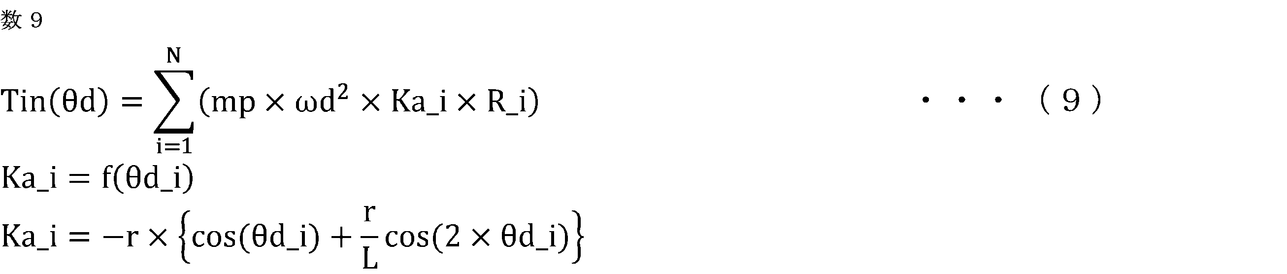
ここで、mpは、ピストンの質量であり、Ka_iは、クランク角速度ωdに基づいてピストンの加速度を演算するための係数であり、各気筒iのクランク角度θd_iの関数になる。例えば、各気筒iの加速度演算係数Ka_iは、式(9)の第3式に基づき、設定されるとよい。式(9)の第3式は、近似式であるが、厳密な値が算出されてもよい。或いは、クランク角度θdと加速度演算係数Kaとの関係が予め設定されたマップデータが用いられてもよい。なお、オフセットクランクの場合は、各気筒iの加速度演算係数Ka_iの算出に、オフセットが考慮されてもよい。各気筒iの変換係数R_iは、式(8)と同様である。また、慣性トルクTinに、コンロッドの慣性等により生じる慣性トルクが加算されてもよい。
そして、第1の軸トルク推定部56は、各クランク角度θdで算出されたガス圧トルクTgasと慣性トルクTinとを合計して、各クランク角度θdの第1の軸トルクの推定値Tcrke1を算出する。

そして、第1の軸トルク推定部56は、各クランク角度θdの第1の軸トルクの推定値Tcrke1に基づいて、各角度区間Sd(n)の第1の軸トルクの推定値Tcrke1(n)を算出する。例えば、各角度区間Sd(n)の中心位置に対応する第1の軸トルクの推定値Tcrke1(n)が算出される。次式に示すように、第1の軸トルク推定部56は、各角度区間Sd(n)の開始クランク角度θd(n-1)の第1の軸トルクの推定値Tcrke1(θd(n-1))と、各角度区間Sd(n)の終了クランク角度θd(n)の第1の軸トルクの推定値Tcrke1(θd(n))との平均値を、各角度区間Sd(n)の第1の軸トルクの推定値Tcrke1(n)として算出する。或いは、第1の軸トルクの推定値Tcrke1の算出に用いられるクランク角度θdが、各角度区間Sdの中心位置に対応するクランク角度θdに設定され、各角度区間Sdの中心位置に対応する第1の軸トルクの推定値Tcrke1が直接演算されてもよい。

<第1の理想角速度算出部57>
第1の理想角速度算出部57は、角度区間Sd(n)のそれぞれの第1の軸トルクの推定値Tcrke1(n)、及びクランク軸系の慣性モーメントIcrkに基づいて、複数の歯が配置された複数のクランク角度(以下、歯の配置クランク角度とも称す)に変動が無く、外部負荷トルクTloadが無いと仮定した第1の理想状態における、角度区間Sdのそれぞれに対応する角速度である第1の理想区間角速度ωid1を算出する。
第1の理想角速度算出部57は、角度区間Sd(n)のそれぞれの第1の軸トルクの推定値Tcrke1(n)、及びクランク軸系の慣性モーメントIcrkに基づいて、複数の歯が配置された複数のクランク角度(以下、歯の配置クランク角度とも称す)に変動が無く、外部負荷トルクTloadが無いと仮定した第1の理想状態における、角度区間Sdのそれぞれに対応する角速度である第1の理想区間角速度ωid1を算出する。
第1の軸トルクの推定値Tcrke1は、クランク機構の物理モデル式を用いて算出されるので、歯の配置クランク角度に変動が無く、外部負荷トルクTloadが無いと仮定した第1の理想状態における軸トルクになる。そして、第1の理想区間角速度ωid1は、第1の軸トルクの推定値Tcrke1に基づいて算出されるので、第1の理想状態における区間角速度になる。
図8に示すように、第1の理想角速度算出部57は、角度区間Sd(n)のそれぞれの第1の軸トルクの推定値Tcrke1(n)、及びクランク軸系の慣性モーメントIcrkに基づいて、角度区間Sd(n)のそれぞれに対応する第1の理想状態の角加速度である第1の理想区間角加速度αid1(n)を算出する。
第1の理想角速度算出部57は、平均処理角度区間Saveの直前の角度区間Sd(Q-1)の第1の理想区間角速度ωid1(Q-1)を、平均処理角度区間Saveの直前の角度区間Sd(Q-1)に対応する、1つ前の平均処理角度区間Saveの最後の角度区間Sd(Q-1)において算出された第2の理想区間角速度ωid2(Q-1)に設定する。或いは、第1の理想角速度算出部57は、平均処理角度区間Saveの直前の角度区間Sd(Q-1)の第1の理想区間角速度ωid1(Q-1)を、平均処理角度区間Saveの直前の角度区間Sd(Q-1)及びその前後の複数の角度区間Sdの検出区間角速度ωsdの平均値に設定してもよい。
そして、第1の理想角速度算出部57は、平均処理角度区間Saveにおいて、第1の理想区間角加速度αid1(n)を積分して、角度区間Sd(n)のそれぞれに対応する第1の理想状態の角速度である第1の理想区間角速度ωid1(n)を算出する。本実施の形態では、第1の理想角速度算出部57は、次式を用いて、第1の理想区間角速度ωid1を算出する。ここで、Qは、平均処理角度区間Saveの最初の角度区間に対応する角度識別番号であり、開始角度に対応する角度区間は、平均処理角度区間Saveの開始角度の直後の角度区間に設定されている。なお、開始角度に対応する角度区間は、開始角度の直前の角度区間に設定されてもよい。Rは、平均処理角度区間Saveの最後の角度区間に対応する角度識別番号である。この算出処理は、平均処理角度区間Saveの各角度区間Sd(n)について行われる。

<検出区間角速度算出部58>
検出区間角速度算出部58は、角度区間Sdのそれぞれについて、補正値Kcによる補正処理後の時間間隔ΔTdc及び角度間隔に基づいて、角度区間Sdに対応する角速度である検出区間角速度ωsdを算出する。
検出区間角速度算出部58は、角度区間Sdのそれぞれについて、補正値Kcによる補正処理後の時間間隔ΔTdc及び角度間隔に基づいて、角度区間Sdに対応する角速度である検出区間角速度ωsdを算出する。
本実施の形態では、次式を用いて、検出区間角速度算出部58は、角度区間Sd(n)のそれぞれに対応する検出区間角速度ωsd(n)を算出する。

<理想平均値算出部59>
理想平均値算出部59は、平均処理角度区間Saveにおいて、第1の理想区間角速度ωid1の平均値ωid1_aveを算出する。
理想平均値算出部59は、平均処理角度区間Saveにおいて、第1の理想区間角速度ωid1の平均値ωid1_aveを算出する。
本実施の形態では、次式が用いられる。ここで、Qは、平均処理角度区間Saveの最初の角度区間に対応する角度識別番号であり、Rは、平均処理角度区間Saveの最後の角度区間に対応する角度識別番号である。

<検出平均値算出部60>
検出平均値算出部60は、平均処理角度区間Saveにおいて、検出区間角速度ωsdの平均値ωsd_aveを算出する。
検出平均値算出部60は、平均処理角度区間Saveにおいて、検出区間角速度ωsdの平均値ωsd_aveを算出する。
本実施の形態では、次式が用いられる。

なお、検出区間角速度ωsdの平均値ωsd_aveとして、一回転時間検出部55により算出された平均検出角速度ωsavedが用いられてもよい。
<外部負荷トルク推定部61>
外部負荷トルク推定部61は、検出区間角速度の平均値ωsd_aveと第1の理想区間角速度の平均値ωid1_aveとの差に基づいて、内燃機関の外部からクランク軸にかかるトルクである外部負荷トルクTloadを推定する。
外部負荷トルク推定部61は、検出区間角速度の平均値ωsd_aveと第1の理想区間角速度の平均値ωid1_aveとの差に基づいて、内燃機関の外部からクランク軸にかかるトルクである外部負荷トルクTloadを推定する。
外部負荷トルクTloadにより、第1の理想区間角速度ωid1と検出区間角速度ωsdとの間に差が生じる。しかし、信号板10の歯の角度ばらつき及び補正値Kcの設定誤差等により、検出区間角速度ωsdは変動する。そのため、瞬間的な第1の理想区間角速度ωid1と検出区間角速度ωsdの差では、検出区間角速度ωsdの変動の影響が大きくなり、外部負荷トルクTloadを精度よく推定できない。上記の構成によれば、検出区間角速度の平均値ωsd_aveと第1の理想区間角速度の平均値ωid1_aveとの差が用いられるので、検出区間角速度ωsdの変動の影響を平滑化して、外部負荷トルクTloadを精度よく推定することができる。
本実施の形態では、次式に示すように、外部負荷トルク推定部61は、検出区間角速度の平均値ωsd_aveから第1の理想区間角速度の平均値ωid1_aveを減算し、2を乗算した値を、平均処理角度区間の時間間隔ΔTsaveで除算した値に、クランク軸系の慣性モーメントIcrkを乗算して、外部負荷トルクTloadを演算する。

式(16)の算出方法の原理を説明する。上述したように、平均処理角度区間Saveの直前の角度区間Sd(Q-1)に対応する、1つ前の平均処理角度区間Saveの最後の角度区間Sd(Q-1)において算出された第2の理想区間角速度ωid2(Q-1)が、平均処理角度区間Saveの直前の角度区間Sd(Q-1)の第1の理想区間角速度ωid1(Q-1)として設定されるため、概ね、検出区間角速度ωsdの挙動に一致する。また、平均処理角度区間Saveにおいて、外部負荷トルクTloadが一定であると仮定し、外部負荷トルクにより生じたクランク角加速度Δαloadは一定であると仮定する。そのため、図9に示すように、外部負荷トルクTloadによるクランク角加速度Δαloadにより生じた、第1の理想区間角速度ωid1からの検出区間角速度ωsdの速度変動量Δωload(=ωsd-ωid1)は、一定の傾きで変化すると仮定される。
そのため、次式に示すように、検出区間角速度の平均値ωsd_aveと第1の理想区間角速度の平均値ωid1_aveとの差は、平均処理角度区間Saveにおける速度変動量Δωloadの平均値に相当する。速度変動量Δωloadの平均値は、平均処理角度区間Saveの終了角度の速度変動Δωload_endを2で除算した値になる。また、平均処理角度区間Saveの終了角度の速度変動Δωload_endは、外部負荷トルクによるクランク角加速度Δαloadに平均処理角度区間Saveを乗算した値になる。外部負荷トルクによるクランク角加速度Δαloadは、外部負荷トルクTloadを慣性モーメントIcrkで除算した値になる。式(17)の各式を相互に代入し、整理すると、式(16)が得られる。
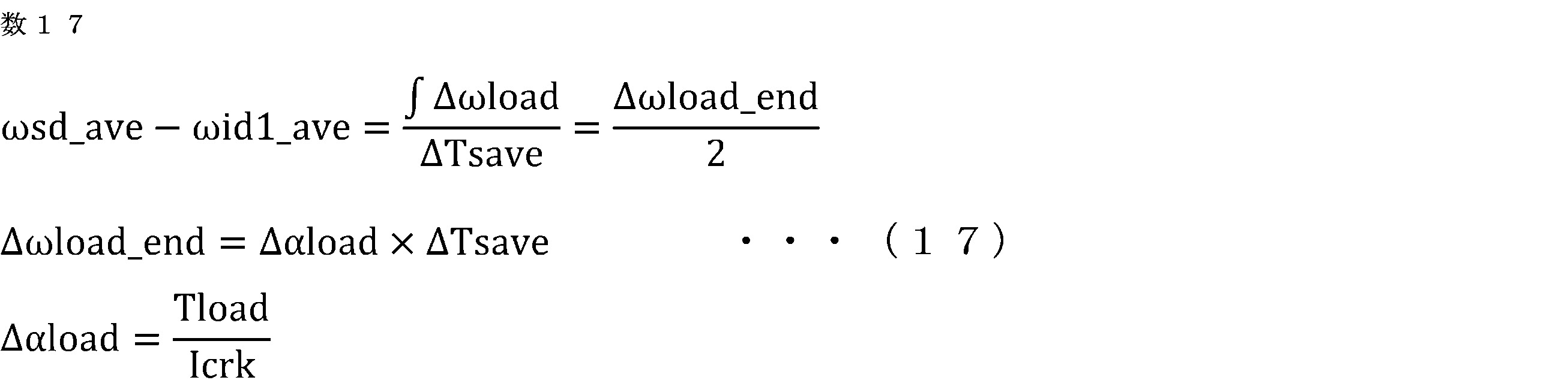
図10に、試験データのタイムチャートを示す。なお、補正値Kcは1に設定されており、検出区間角速度ωsdは、信号板10の歯の角度ばらつきにより変動している。平均処理角度区間Saveの開始角度では、第1の理想区間角速度ωid1は、検出区間角速度ωsdに一致しているが、その後、外部負荷トルクによるクランク角加速度Δαloadにより、検出区間角速度ωsdは、第1の理想区間角速度ωid1から次第に低下していき、速度変動量Δωload(=ωsd-ωid1)が次第に大きくなっている。一方、検出区間角速度ωsdは変動しているため、速度変動量Δωload(=ωsd-ωid1)も変動している。よって、瞬間的な第1の理想区間角速度ωid1と検出区間角速度ωsdの差では、検出区間角速度ωsdの変動の影響が大きくなり、外部負荷トルクTloadを精度よく推定できない。検出区間角速度の平均値ωsd_aveと第1の理想区間角速度の平均値ωid1_aveとの差が用いられるので、検出区間角速度ωsdの変動の影響を平滑化して、外部負荷トルクTloadを精度よく推定することができる。
図11に、図10に対して、精度よく推定された外部負荷トルクTloadを用いて算出された第2の理想区間角速度ωid2を重ね書きしたタイムチャートを示す。第2の理想区間角速度ωid2は、検出区間角速度ωsdに重なっており、第2の理想区間角速度ωid2と検出区間角速度ωsdとを比較することにより、補正値Kcを精度よく変化できることが理解できる。
図12の上段に、クランク角加速度αdに慣性トルクTinを乗算して得られた実軸トルクTcrkdと第2の軸トルクの推定値Tcrke2のタイムチャートを示し、中段に、上死点付近の実軸トルクTcrkdに慣性トルクTinを乗算して算出した外部負荷トルクTloadの比較例のタイムチャートを示し、下段に、本実施の形態による外部負荷トルクTloadのタイムチャートを示す。中段の比較例では、平均処理角度区間Saveごとに上死点付近の検出区間角速度ωsdの変動量が異なっており、平均処理角度区間Saveごとに外部負荷トルクTloadが大きく変動している。一方、下段の本実施の形態では、平均処理角度区間Saveの間の検出区間角速度ωsdの変動の影響が平滑化されているので、平均処理角度区間Saveごとの外部負荷トルクTloadの変動量が小さくなっており、外部負荷トルクTloadを精度よく推定できている。
本実施の形態では、外部負荷トルク推定部61は、内燃機関が燃焼を行っていない未燃焼状態である場合(第1条件の成立時)に、外部負荷トルクTloadを推定する。一方、外部負荷トルク推定部61は、内燃機関が燃焼を行っている燃焼状態である場合(第1条件の不成立時)は、外部負荷トルクTloadを推定しない。未燃焼状態には、燃料の供給を停止している燃料カット状態などがある。
未燃焼状態では、クランク機構の物理モデル式が想定していない燃焼による筒内圧の上昇がないため、第1の理想区間角速度ωid1の算出精度が向上する。よって、外部負荷トルクTloadの推定精度を向上させることができる。外部負荷トルクTloadの推定の詳細な実行条件は、後述する補正値Kcの変化の詳細な実行条件と同じであり、説明を省略する。
なお、外部負荷トルク推定部61は、今回及び過去の平均処理角度区間Saveに対応して推定された外部負荷トルクTloadに対して平滑化処理を行った値を、最終的な外部負荷トルクTloadとして算出してもよい。
外部負荷トルクTloadの推定の実行条件が成立している状態では、外部負荷トルクTloadの変化速度は遅いため、複数の平均処理角度区間Saveの平滑化処理を行うことにより、外部負荷トルクTloadの演算精度を更に向上させることができる。
例えば、平滑化処理として、移動平均処理、加重平均処理、一次遅れ等のローパスフィルタ処理が用いられる。
<歯の配置クランク角度の変動による課題>
リングギア25の歯の製造誤差及び経年変化により、各歯が配置されたクランク角度が6度ごとの規定の角度から変動する。図13に、歯の配置クランク角度に変動が生じた場合に、補正値Kcにより補正されていない角度間隔Δθd及び時間間隔ΔTdに基づいて算出された補正処理なしのクランク角速度ωdcmpと、計測用に設けられた高精度の回転センサにより検出した高精度のクランク角速度ω*との挙動を示す。図13に示すように、各歯の配置クランク角度の変動により、補正処理なしのクランク角速度ωdcmpは、計測用の高精度のクランク角速度ω*に対して変動している。
リングギア25の歯の製造誤差及び経年変化により、各歯が配置されたクランク角度が6度ごとの規定の角度から変動する。図13に、歯の配置クランク角度に変動が生じた場合に、補正値Kcにより補正されていない角度間隔Δθd及び時間間隔ΔTdに基づいて算出された補正処理なしのクランク角速度ωdcmpと、計測用に設けられた高精度の回転センサにより検出した高精度のクランク角速度ω*との挙動を示す。図13に示すように、各歯の配置クランク角度の変動により、補正処理なしのクランク角速度ωdcmpは、計測用の高精度のクランク角速度ω*に対して変動している。
図14に、各クランク角度における、補正処理なしのクランク角速度ωdcmpを計測用の高精度のクランク角速度ω*で除算した角速度比を示す。角速度比が、1より大きい場合は、実際の角度間隔が、規定の角度間隔(6度)よりも短くなっており、1よりも小さい場合は、実際の角度間隔が、規定の角度間隔(6度)よりも長くなっている。よって、歯の配置クランク角度の変動を打ち消すように、補正値Kcを適切に変化させ、補正値Kcにより補正を行わないと、算出したクランク角速度ωd及びクランク角加速度αdに高周波成分が重畳し、燃焼状態の推定、及び燃焼制御等の内燃機関の制御精度が悪化する。以下で、補正値Kcを適切に変化させるための処理について説明する。
<第2の軸トルク推定部62>
第2の軸トルク推定部62は、角度区間Sd(n)のそれぞれの第1の軸トルクの推定値Tcrke1(n)に外部負荷トルクTloadを加算して、角度区間Sd(n)のそれぞれの第2の軸トルクの推定値Tcrke2(n)を算出する。

第2の軸トルク推定部62は、角度区間Sd(n)のそれぞれの第1の軸トルクの推定値Tcrke1(n)に外部負荷トルクTloadを加算して、角度区間Sd(n)のそれぞれの第2の軸トルクの推定値Tcrke2(n)を算出する。
<第2の理想角速度算出部63>
第2の理想角速度算出部63は、角度区間Sd(n)のそれぞれの第2の軸トルクの推定値Tcrke2(n)、及びクランク軸系の慣性モーメントIcrkに基づいて、複数の歯が配置された複数のクランク角度(以下、歯の配置クランク角度とも称す)に変動が無いと仮定した第2の理想状態における、角度区間Sdのそれぞれに対応する角速度である第2の理想区間角速度ωid2を算出する。
第2の理想角速度算出部63は、角度区間Sd(n)のそれぞれの第2の軸トルクの推定値Tcrke2(n)、及びクランク軸系の慣性モーメントIcrkに基づいて、複数の歯が配置された複数のクランク角度(以下、歯の配置クランク角度とも称す)に変動が無いと仮定した第2の理想状態における、角度区間Sdのそれぞれに対応する角速度である第2の理想区間角速度ωid2を算出する。
第2の軸トルクの推定値Tcrke2は、クランク機構の物理モデル式を用いて算出された第1の軸トルクの推定値Tcrk1に外部負荷トルクTloadが加算されて算出されるので、歯の配置クランク角度に変動が無いと仮定した第2の理想状態における軸トルクになる。そして、第2の理想区間角速度ωid2は、第2の軸トルクの推定値Tcrke2に基づいて算出されるので、第2の理想状態における区間角速度になる。
本実施の形態では、第2の理想角速度算出部63は、平均処理角度区間Saveにおける検出区間角速度ωsdの平均値ωsd_aveが、平均検出角速度ωsavedから逸脱しないように、角度区間Sd(n)のそれぞれの補正値Kc(n)を変化させるために、平均処理角度区間Saveにおける第2の理想区間角速度ωid2の平均値ωid2_aveを平均検出角速度ωsavedに一致させる。
図15に示すように、第2の理想角速度算出部63は、角度区間Sd(n)のそれぞれの第2の軸トルクの推定値Tcrke2(n)、及びクランク軸系の慣性モーメントIcrkに基づいて、角度区間Sd(n)のそれぞれに対応する第2の理想状態の角加速度である第2の理想区間角加速度αid2(n)を算出し、第2の理想区間角加速度αid2(n)を積分して、角度区間Sd(n)のそれぞれに対応する第2の理想状態の角速度である仮の第2の理想区間角速度ωid2tmp(n)を算出する。本実施の形態では、第2の理想角速度算出部63は、次式を用いて、仮の第2の理想区間角速度ωid2tmpを算出する。この算出処理は、平均処理角度区間Saveの各角度区間Sd(n)について行われる。

次式に示すように、第2の理想角速度算出部63は、平均処理角度区間Saveにおける仮の第2の理想区間角速度ωid2tmpの平均値ωid2tmp_aveを算出する。ここで、Qは、平均処理角度区間Saveの最初の角度区間に対応する角度識別番号であり、Rは、平均処理角度区間Saveの最後の角度区間に対応する角度識別番号である。

そして、次式に示すように、第2の理想角速度算出部63は、仮の第2の理想区間角速度ωid2tmpから、仮の第2の理想区間角速度の平均値ωid2tmp_aveを減算し、平均検出角速度ωsavedを加算した値を、第2の理想区間角速度ωid2として算出する。この算出処理は、平均処理角度区間Saveの各角度区間Sd(n)について行われる。

この算出処理により、平均処理角度区間Saveにおける第2の理想区間角速度ωid2の平均値ωid2_aveを平均検出角速度ωsavedに一致させることができる。よって、後述するように、検出区間角速度ωsdが第2の理想区間角速度ωid2に近づくように、補正値Kcが変化されるので、平均処理角度区間Saveにおける検出区間角速度ωsdの平均値ωsd_aveが、平均検出角速度ωsavedから逸脱しないように、補正値Kcを変化させることができる。
図16に、一定のクランク角速度の条件で、仮の第2の理想区間角速度ωid2tmpが、そのまま第2の理想区間角速度ωid2に設定される場合の制御挙動を示す。この場合は、第2の理想区間角速度ωid2の平均値ωid2_aveが、平均検出角速度ωsavedからずれるため、検出区間角速度ωsdの平均値ωsd_aveが、平均検出角速度ωsavedから逸脱し、クランク角速度が一定であるにもかかわらず、検出区間角速度ωsdが、次第にシフトし、誤差が生じている。一方、図17に、式(21)のように補正した場合の制御挙動を示す。この場合は、第2の理想区間角速度ωid2の平均値ωid2_aveが、平均検出角速度ωsavedに一致しているため、検出区間角速度ωsdの平均値ωsd_aveが、平均検出角速度ωsavedから逸脱しないようにでき、検出区間角速度ωsdが、シフトしておらず、誤差が生じていない。
<補正値変化部64>
補正値変化部64は、角度区間Sd(n)のそれぞれについて、補正値Kcによる補正処理後の時間間隔ΔTdc及び角度間隔Δθdcにより算出される角度区間に対応する角速度である検出区間角速度ωsd(n)が、第2の理想区間角速度ωid2(n)に近づくように、角度区間Sd(n)のそれぞれの補正値Kc(n)を変化させる。
補正値変化部64は、角度区間Sd(n)のそれぞれについて、補正値Kcによる補正処理後の時間間隔ΔTdc及び角度間隔Δθdcにより算出される角度区間に対応する角速度である検出区間角速度ωsd(n)が、第2の理想区間角速度ωid2(n)に近づくように、角度区間Sd(n)のそれぞれの補正値Kc(n)を変化させる。
この構成によれば、第2の理想区間角速度ωid2は、第2の理想状態における区間角速度であるので、歯の配置クランク角度の変動による高周波成分が重畳していない。精度よく推定された外部負荷トルクTloadが反映されているので、第2の理想区間角速度ωid2の精度がよい。よって、検出区間角速度ωsd(n)が、第2の理想区間角速度ωid2(n)に近づくように、各角度区間Sd(n)の補正値Kc(n)を変化させることより、歯の配置クランク角度の変動を打ち消すように、補正値Kc(n)を適切に変化させることができる。
補正値変化部64は、角度区間Sd(n)のそれぞれについて、検出区間角速度ωsd(n)が第2の理想区間角速度ωid2(n)を上回った場合は、補正値Kc(n)を増加させ、検出区間角速度ωsd(n)が第2の理想区間角速度ωid2(n)を下回った場合は、補正値Kc(n)を減少させる。
例えば、補正値変化部64は、次式を用いて、補正値Kc(n)を更新する。ここで、Klrnは、学習率であり、1以下の値が設定される。

本実施の形態では、補正値変化部64は、平均処理角度区間Saveの各角度区間Sd(n)の第2の理想区間角速度ωid2(n)の算出処理が終了するごとに、平均処理角度区間Saveの各角度区間Sd(n)の補正値Kc(n)の変化処理をまとめて実行する。
本実施の形態では、補正値変化部64は、内燃機関が燃焼を行っていない未燃焼状態である場合(第1条件の成立時)に、補正値Kcを変化させる。一方、補正値変化部64は、内燃機関が燃焼を行っている燃焼状態である場合(第1条件の不成立時)は、補正値Kcを変化させない。未燃焼状態には、燃料の供給を停止している燃料カット状態などがある。
未燃焼状態では、クランク機構の物理モデル式が想定していない燃焼による筒内圧の上昇がないため、第2の理想区間角速度ωid2の算出精度が向上する。よって、補正値Kc変化の精度を向上させることができる。
また、補正値変化部64は、検出区間角速度ωsdの平均値の変化量の絶対値が、変化量判定値以下である場合(第2条件の成立時)に、補正値Kcを変化させる。一方、補正値変化部64は、変化量の絶対値が、変化量判定値を上回っている場合(第2条件の不成立時)は、補正値Kcを変化させない。検出区間角速度ωsdの平均値は、例えば、平均処理角度区間Save又は行程周期などの平均期間の平均値とされる。
検出区間角速度ωsdの平均値の変化量の絶対値が大きい場合は、外部負荷トルクTload等の外乱の影響が大きく、外乱の影響により、補正値Kc変化の精度が悪化する可能性がある。よって、検出区間角速度ωsdの平均値の変化量の絶対値が小さい安定した状態で、補正値Kcを変化させることで、補正値Kc変化の精度を向上させることができる。
補正値変化部64は、内燃機関が搭載された車両のブレーキ機構の動作量が、動作量判定値以下である場合(第3条件の成立時)に、補正値Kcを変化させる。一方、補正値変化部64は、ブレーキ機構の動作量が、動作量判定値を上回っている場合(第3条件の不成立時)は、補正値Kcを変化させない。
ブレーキ機構の動作量が大きい場合は、ブレーキの制動力により、外部負荷トルクTloadが大きく変動し、補正値Kc変化の精度が悪化する可能性がある。よって、ブレーキ機構の動作量が小さい安定した状態で、補正値Kcを変化させることで、補正値Kc変化の精度を向上させることができる。
補正値変化部64は、クランク軸が連結されたクラッチ機構が解放状態である場合(第4条件の成立時)に、補正値Kcを変化させる。一方、補正値変化部64は、クラッチ機構が連結状態である場合(第4条件の不成立時)は、補正値Kcを変化させない。例えば、クラッチ機構は、クランク軸と変速装置との間に設けられる。
クラッチ機構が連結状態である場合は、車輪側から伝達される外部負荷トルクTloadにより、補正値Kc変化の精度が悪化する可能性がある。よって、クラッチ機構が解放状態である場合に、補正値Kcを変化させることで、補正値Kc変化の精度を向上させることができる。
補正値変化部64は、内燃機関の冷却水温が、第1の水温判定値以上である場合(第5条件の成立時)に、補正値Kcを変化させる。一方、補正値変化部64は、冷却水温が、第1の水温判定値未満である場合(第5条件の不成立時)は、補正値Kcを変化させない。或いは、補正値変化部64は、冷却水温が、第1の水温判定値以上でかつ、第1の水温判定値よりも高い第2の水温判定値以下である場合(第5条件の成立時)に、補正値Kcを変化させる。補正値変化部64は、冷却水温が、第1の水温判定値未満である、又は冷却水温が、第2の水温判定値よりも大きい場合(第5条件の不成立時)は、補正値Kcを変化させない。第1の水温判定値及び第2の水温判定値は、内燃機関が暖機され、冷却水温が通常の運転温度である場合に、補正値Kcが変化されるような値に予め設定される。
冷却水温が通常の運転温度になると、内燃機関のフリクション等の状態が安定し、補正値Kc変化の精度を向上させることができる。
本実施の形態では、補正値変化部64は、上記の第1条件から第5条件が全て成立している場合に、補正値Kcを変化させ、第1条件から第5条件のいずれか一つが成立していない場合に、補正値Kcを変化させない。或いは、第1条件から第5条件の全てが用いられなくてもよく、少なくとも第1条件が用いられてもよい。
図18に、歯の配置クランク角度に変動が生じた場合に、補正値Kcにより補正されていない角度間隔Δθd及び時間間隔ΔTdに基づいて算出した補正処理なしのクランク角速度ωdcmpと、計測用に設けられた高精度の回転センサにより検出した高精度のクランク角速度ω*と、補正値Kcによる補正処理後のクランク角速度ωdと、の挙動を示す。図18に示すように、補正処理後のクランク角速度ωdは、補正処理なしのクランク角速度ωdcmpから計測用の高精度のクランク角速度ω*に近づいている。よって、歯の配置クランク角度の変動を打ち消すように、補正値Kcを適切に変化させることができ、クランク角度θdの検出誤差を精度良く補正することができている。
<異常判定部65>
異常判定部65は、今回及び過去の平均処理角度区間Saveに対応して推定された外部負荷トルクTloadに対して平滑化処理を行って、外部負荷トルクの平滑値Tload_aveを算出し、今回の平均処理角度区間Saveに対応して推定された外部負荷トルクTloadと外部負荷トルクの平滑値Tload_aveとのトルク差ΔTloadを算出し、トルク差ΔTloadと、今回の平均処理角度区間Saveに対応する圧縮行程の気筒の番号iに基づいて、異常が発生した気筒を判定する。上述したように、平均区間設定部54は、各気筒の圧縮行程に対応させて、平均処理角度区間Saveを設定する。
異常判定部65は、今回及び過去の平均処理角度区間Saveに対応して推定された外部負荷トルクTloadに対して平滑化処理を行って、外部負荷トルクの平滑値Tload_aveを算出し、今回の平均処理角度区間Saveに対応して推定された外部負荷トルクTloadと外部負荷トルクの平滑値Tload_aveとのトルク差ΔTloadを算出し、トルク差ΔTloadと、今回の平均処理角度区間Saveに対応する圧縮行程の気筒の番号iに基づいて、異常が発生した気筒を判定する。上述したように、平均区間設定部54は、各気筒の圧縮行程に対応させて、平均処理角度区間Saveを設定する。
気筒の圧縮抜け、気筒内のカーボン堆積が生じると、圧縮行程の実ガス圧が、正常なガス圧及び推定した気筒内のガス圧Pcylから逸脱する。このガス圧の異常が生じた気筒の圧縮行程において、外部負荷トルクTloadが、外部負荷トルクの平滑値Tload_aveから逸脱する。よって、上記の構成によれば、内燃機関の異常を判定することができる。
異常判定部65は、今回の平均処理角度区間Saveに対応して算出されたトルク差ΔTloadの絶対値が、判定閾値を超えた場合に、今回の平均処理角度区間Saveに対応する圧縮行程の気筒に異常が発生したと判定する。トルク差ΔTloadの正側と負側とで、判定閾値を異ならせてもよい。また、異常判定部65は、異常判定された頻度が、判定頻度よりも大きくなった場合に、最終的に異常が判定したと判定してもよい。異常判定部65は、警告灯をオンにするなどして、異常の発生をユーザに報知する。
2.実施の形態2
実施の形態2に係る制御装置50について図面を参照して説明する。上記の実施の形態1と同様の構成部分は説明を省略する。本実施の形態に係る制御装置50の基本的な構成は実施の形態1と同様であるが、第1の理想角速度算出部57及び第2の理想角速度算出部63の処理が実施の形態1と異なる。
実施の形態2に係る制御装置50について図面を参照して説明する。上記の実施の形態1と同様の構成部分は説明を省略する。本実施の形態に係る制御装置50の基本的な構成は実施の形態1と同様であるが、第1の理想角速度算出部57及び第2の理想角速度算出部63の処理が実施の形態1と異なる。
<第1の理想角速度算出部57>
実施の形態1と同様に、第1の理想角速度算出部57は、角度区間Sd(n)のそれぞれの第1の軸トルクの推定値Tcrke1(n)、及びクランク軸系の慣性モーメントIcrkに基づいて、歯の配置クランク角度に変動が無く、外部負荷トルクTloadが無いと仮定した第1の理想状態における、角度区間Sdのそれぞれに対応する角速度である第1の理想区間角速度ωid1を算出する。
実施の形態1と同様に、第1の理想角速度算出部57は、角度区間Sd(n)のそれぞれの第1の軸トルクの推定値Tcrke1(n)、及びクランク軸系の慣性モーメントIcrkに基づいて、歯の配置クランク角度に変動が無く、外部負荷トルクTloadが無いと仮定した第1の理想状態における、角度区間Sdのそれぞれに対応する角速度である第1の理想区間角速度ωid1を算出する。
図19に示すように、第1の理想角速度算出部57は、角度区間Sd(n)のそれぞれの第1の軸トルクの推定値Tcrke1(n)、及びクランク軸系の慣性モーメントIcrkに基づいて、角度区間Sd(n)のそれぞれに対応する第1の理想状態の角加速度である第1の理想区間角加速度αid1(n)を算出する。この算出処理は、平均処理角度区間Saveの各角度区間Sd(n)について行われる。

実施の形態1と異なり、第1の理想角速度算出部57は、角度区間Sdを一つずつ進角側に変化させて演算対象の角度区間Scal(n)を設定し、演算対象の角度区間Scal(n)に対応する第1の理想区間角加速度αid1(n)、及び一つ遅角側の演算対象の角度区間Scal(n-1)において算出された第1の理想区間角速度ωid1(n-1)に基づいて、演算対象の角度区間Scal(n)に対応する第1の理想状態の時間間隔である第1の理想時間間隔ΔTid1(n)を算出し、演算対象の角度区間Scal(n)に対応する第1の理想時間間隔ΔTid1(n)に基づいて、演算対象の角度区間Scal(n)に対応する第1の理想状態の角速度である第1の理想区間角速度ωid1(n)を算出する。
本実施の形態では、平均処理角度区間Saveの各角度区間Sd(n)が、平均処理角度区間Saveの最初の角度区間Sd(Q)から最後の角度区間Sd(R)まで一つずつ進角側に変化され、演算対象の角度区間Scal(n)に設定される(n=Q、Q+1、・・・、R-1、R)。ここで、Qは、平均処理角度区間Saveの最初の角度区間に対応する角度識別番号であり、Rは、平均処理角度区間Saveの終了角度間隔に対応する角度識別番号である。
次式を用いて、第1の理想角速度算出部57は、演算対象の角度区間Scal(n)に対応する第1の理想区間角加速度αid1(n)、及び一つ遅角側の演算対象の角度区間Scal(n-1)において算出された第1の理想区間角速度ωid1(n-1)に基づいて、演算対象の角度区間Scal(n)に対応する第1の理想状態の時間間隔である第1の理想時間間隔ΔTid1(n)を算出する。

次式を用いて、第1の理想角速度算出部57は、演算対象の角度区間Scal(n)に対応する第1の理想時間間隔ΔTid1(n)に基づいて、演算対象の角度区間Scal(n)に対応する第1の理想状態の角速度である第1の理想区間角速度ωid1(n)を算出する。

角度識別番号nをQからRまで一つずつ増加させながら、各角度識別番号nで、式(24)及び式(25)の演算が行われる。
第1の理想角速度算出部57は、平均処理角度区間Saveの開始角度の第1の理想区間角速度ωid1を、平均処理角度区間Saveの開始角度の検出区間角速度ωsdに設定する。
<第2の理想角速度算出部63>
実施の形態1と同様に、第2の理想角速度算出部63は、角度区間Sd(n)のそれぞれの第2の軸トルクの推定値Tcrke2(n)、及びクランク軸系の慣性モーメントIcrkに基づいて、歯の配置クランク角度に変動が無いと仮定した第2の理想状態における、角度区間Sdのそれぞれに対応する角速度である第2の理想区間角速度ωid2を算出する。
実施の形態1と同様に、第2の理想角速度算出部63は、角度区間Sd(n)のそれぞれの第2の軸トルクの推定値Tcrke2(n)、及びクランク軸系の慣性モーメントIcrkに基づいて、歯の配置クランク角度に変動が無いと仮定した第2の理想状態における、角度区間Sdのそれぞれに対応する角速度である第2の理想区間角速度ωid2を算出する。
また、第2の理想角速度算出部63は、平均処理角度区間Saveにおける検出区間角速度ωsdの平均値ωsd_aveが、平均検出角速度ωsavedから逸脱しないように、角度区間Sd(n)のそれぞれの補正値Kc(n)を変化させるために、平均処理角度区間Saveにおける第2の理想区間角速度ωid2の平均値ωid2_aveを平均検出角速度ωsavedに一致させる。
図20に示すように、第2の理想角速度算出部63は、角度区間Sd(n)のそれぞれの第2の軸トルクの推定値Tcrke2(n)、及びクランク軸系の慣性モーメントIcrkに基づいて、角度区間Sd(n)のそれぞれに対応する第2の理想状態の角加速度である第2の理想区間角加速度αid2(n)を算出する。この算出処理は、平均処理角度区間Saveの各角度区間Sd(n)について行われる。

実施の形態1と異なり、第2の理想角速度算出部63は、角度区間Sdを一つずつ進角側に変化させて演算対象の角度区間Scal(n)を設定し、演算対象の角度区間Scal(n)に対応する第2の理想区間角加速度αid2(n)、及び一つ遅角側の演算対象の角度区間Scal(n-1)において算出された仮の第2の理想区間角速度ωid2tmp(n-1)に基づいて、演算対象の角度区間Scal(n)に対応する第2の理想状態の時間間隔である第2の理想時間間隔ΔTid2(n)を算出し、演算対象の角度区間Scal(n)に対応する第2の理想時間間隔ΔTid2(n)に基づいて、演算対象の角度区間Scal(n)に対応する第2の理想状態の角速度である仮の第2の理想区間角速度ωid2tmp(n)を算出する。
本実施の形態では、平均処理角度区間Saveの各角度区間Sd(n)が、平均処理角度区間Saveの最初の角度区間Sd(Q)から最後の角度区間Sd(R)まで一つずつ進角側に変化され、演算対象の角度区間Scal(n)に設定される(n=Q、Q+1、・・・、R-1、R)。ここで、Qは、平均処理角度区間Saveの最初の角度区間に対応する角度識別番号であり、Rは、平均処理角度区間Saveの終了角度間隔に対応する角度識別番号である。
次式を用いて、第2の理想角速度算出部63は、演算対象の角度区間Scal(n)に対応する第2の理想区間角加速度αid2(n)、及び一つ遅角側の演算対象の角度区間Scal(n-1)において算出された仮の第2の理想区間角速度ωid2tmp(n-1)に基づいて、演算対象の角度区間Scal(n)に対応する第2の理想状態の時間間隔である第2の理想時間間隔ΔTid2(n)を算出する。
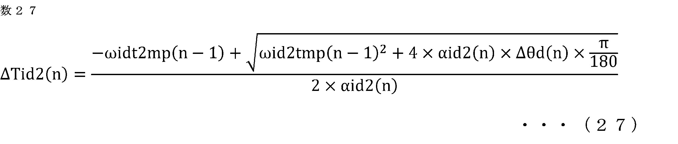
次式を用いて、第2の理想角速度算出部63は、演算対象の角度区間Scal(n)に対応する第2の理想時間間隔ΔTid2(n)に基づいて、演算対象の角度区間Scal(n)に対応する第2の理想状態の角速度である仮の第2の理想区間角速度ωid2tmp(n)を算出する。

角度識別番号nをQからRまで一つずつ増加させながら、各角度識別番号nで、式(27)及び式(28)の演算が行われる。
そして、次式に示すように、第2の理想角速度算出部63は、平均処理角度区間Saveにおける仮の第2の理想区間角速度ωid2tmpの平均値ωid2tmp_aveを算出する。

次式に示すように、第2の理想角速度算出部63は、仮の第2の理想区間角速度ωid2tmpから、仮の第2の理想区間角速度の平均値ωid2tmp_aveを減算し、平均検出角速度ωsavedを加算した値を、第2の理想区間角速度ωid2として算出する。この算出処理は、平均処理角度区間Saveの各角度区間Sd(n)について行われる。

3.実施の形態3
実施の形態3に係る制御装置50について図面を参照して説明する。上記の実施の形態1又は2と同様の構成部分は説明を省略する。本実施の形態に係る制御装置50の基本的な構成は実施の形態1又は2と同様であるが、補正値変化部64の処理が実施の形態1又は2と異なる。
実施の形態3に係る制御装置50について図面を参照して説明する。上記の実施の形態1又は2と同様の構成部分は説明を省略する。本実施の形態に係る制御装置50の基本的な構成は実施の形態1又は2と同様であるが、補正値変化部64の処理が実施の形態1又は2と異なる。
本実施の形態では、補正値変化部64は、平均処理角度区間Saveにおける検出区間角速度ωsdの平均値ωsd_aveが、平均検出角速度ωsavedから逸脱しないように、角度区間Sd(n)のそれぞれの補正値Kc(n)を変化させるために、平均処理角度区間Saveにおける検出区間角速度ωsdの平均値ωsd_aveを平均検出角速度ωsavedに一致させる。
図21に示すように、補正値変化部64は、補正値による補正処理後の時間間隔ΔTdc(n)及び角度間隔Δθdc(n)に基づいて、角度区間Sd(n)のそれぞれに対応する角速度である基礎の検出区間角速度ωsdbs(n)を算出する。この算出処理には、次式が用いられる。この算出処理は、平均処理角度区間Saveの各角度区間Sd(n)について行われる。

補正値変化部64は、角度区間Sd(n)のそれぞれに対応する基礎の検出区間角速度ωsdbs(n)及び時間間隔ΔTdc(n)に基づいて、角度区間Sd(n)のそれぞれに対応する角加速度である基礎の検出区間角加速度αsdbs(n)を算出し、基礎の検出区間角加速度αsdbs(n)を積分して、角度区間Sd(n)のそれぞれに対応する角速度である仮の検出区間角速度ωsdtmp(n)を算出する。この算出処理には、次式が用いられる。この算出処理は、平均処理角度区間Saveの各角度区間Sd(n)について行われる。

補正値変化部64は、平均処理角度区間Saveにおける仮の検出区間角速度ωsdtmpの平均値ωsdtmp_aveを算出する。

そして、次式に示すように、補正値変化部64は、仮の検出区間角速度ωsdtmp(n)から、仮の検出区間角速度の平均値ωsdtmp_aveを減算し、平均検出角速度ωsavedを加算した値を、検出区間角速度ωsd(n)として算出する。この算出処理は、平均処理角度区間Saveの角度区間Sd(n)について行われる。

この算出処理により、平均処理角度区間Saveにおける検出区間角速度の平均値ωsd_aveを平均検出角速度ωsavedに一致させることができる。よって、平均処理角度区間Saveにおける検出区間角速度ωsdの平均値ωsd_aveが、平均検出角速度ωsavedから逸脱しないように、補正値Kcを変化させることができる。
そして、実施の形態1と同様に、補正値変化部64は、角度区間Sd(n)のそれぞれについて、検出区間角速度ωsd(n)が、第2の理想区間角速度ωid2(n)に近づくように、角度区間Sd(n)のそれぞれの補正値Kc(n)を変化させる。
〔その他の実施の形態〕
(1)上記の各実施の形態においては、第2クランク角センサ6が、本願における「特定クランク角センサ」に相当し、フライホイール27が、本願における「回転部材」に相当し、フライホイール27に設けられたリングギア25の歯が、本願における「被検出部」に相当する場合を例に説明した。しかし、本願の実施の形態はこれに限定されない。すなわち、第1クランク角センサ11が、本願における「特定クランク角センサ」に相当し、信号板10が、本願における「回転部材」に相当し、信号板10に設けられた複数の歯が、本願における「被検出部」に相当してもよい。
(1)上記の各実施の形態においては、第2クランク角センサ6が、本願における「特定クランク角センサ」に相当し、フライホイール27が、本願における「回転部材」に相当し、フライホイール27に設けられたリングギア25の歯が、本願における「被検出部」に相当する場合を例に説明した。しかし、本願の実施の形態はこれに限定されない。すなわち、第1クランク角センサ11が、本願における「特定クランク角センサ」に相当し、信号板10が、本願における「回転部材」に相当し、信号板10に設けられた複数の歯が、本願における「被検出部」に相当してもよい。
(2)上記の各実施の形態においては、内燃機関1は、ガソリンエンジンとされている場合を例として説明した。しかし、本願の実施の形態はこれに限定されない。すなわち、内燃機関1は、ディーゼルエンジン、HCCI燃焼(Homogeneous-Charge Compression Ignition Combustion)を行うエンジン等の各種の内燃機関とされてもよい。
本願は、様々な例示的な実施の形態及び実施例が記載されているが、1つ、または複数の実施の形態に記載された様々な特徴、態様、及び機能は特定の実施の形態の適用に限られるのではなく、単独で、または様々な組み合わせで実施の形態に適用可能である。従って、例示されていない無数の変形例が、本願明細書に開示される技術の範囲内において想定される。例えば、少なくとも1つの構成要素を変形する場合、追加する場合または省略する場合、さらには、少なくとも1つの構成要素を抽出し、他の実施の形態の構成要素と組み合わせる場合が含まれるものとする。
1:内燃機関、50:内燃機関の制御装置、51:吸気管ガス圧検出部、52:角度情報検出部、53:角度情報補正部、54:平均区間設定部、55:一回転時間検出部、56:第1の軸トルク推定部、57:第1の理想角速度算出部、58:検出区間角速度算出部、59:理想平均値算出部、60:検出平均値算出部、61:外部負荷トルク推定部、62:第2の軸トルク推定部、63:第2の理想角速度算出部、64:補正値変化部、65:異常判定部、Icrk:慣性モーメント、Kc:補正値、Pcyl:ガス圧、Save:平均処理角度区間、Sd:角度区間、Tcrkd:実軸トルク、Tcrke1:第1の軸トルクの推定値、Tcrke2:第2の軸トルクの推定値、Td:検出時刻、Tload:外部負荷トルク、Tload_ave:外部負荷トルクの平滑値、αd:クランク角加速度、αid1:第1の理想区間角加速度、αid2:第2の理想区間角加速度、θd:クランク角度(検出角度)、θd:検出角度、ωd:クランク角速度、ωid1:第1の理想区間角速度、ωid1_ave:第1の理想区間角速度の平均値、ωid2:第2の理想区間角速度、ωid2_ave:第2の理想区間角速度の平均値、ωsaved:平均検出角速度、ωsd:検出区間角速度、ωsd_ave:検出区間角速度の平均値
Claims (8)
- クランク軸と一体回転する回転部材に、予め定められた複数のクランク角度に設けられた複数の被検出部と、非回転部材に固定され、前記被検出部を検出する特定クランク角センサと、吸気管内のガス圧を検出するガス圧センサと、を備えた内燃機関を制御する内燃機関の制御装置であって、
前記特定クランク角センサの出力信号に基づいて、クランク角度を検出すると共に前記クランク角度を検出した検出時刻を検出し、検出した前記クランク角度である検出角度に基づいて、前記検出角度の間の角度区間に対応する角度間隔を算出し、前記検出時刻に基づいて、前記角度区間に対応する時間間隔を算出する角度情報検出部と、
前記角度区間のそれぞれの前記角度間隔又は前記時間間隔を、前記角度区間のそれぞれに対応して1つずつ設けた補正値により補正する角度情報補正部と、
前記ガス圧センサの出力信号に基づいて、前記吸気管内のガス圧を検出する吸気管ガス圧検出部と、
前記吸気管内のガス圧の検出値、及び前記検出角度に基づき、クランク機構の物理モデル式を用いて、気筒内のガス圧及びピストンの往復運動によるクランク軸の軸トルクである第1の軸トルクの推定値を、前記角度区間のそれぞれに対応して推定する第1の軸トルク推定部と、
前記角度区間のそれぞれの前記第1の軸トルクの推定値、及びクランク軸系の慣性モーメントに基づいて、前記複数の被検出部が配置された前記複数のクランク角度に変動が無く、外部負荷トルクが無いと仮定した第1の理想状態における、前記角度区間のそれぞれに対応する角速度である第1の理想区間角速度を算出する第1の理想角速度算出部と、
前記角度区間のそれぞれについて、前記補正値による補正処理後の前記時間間隔及び前記角度間隔に基づいて、前記角度区間に対応する角速度である検出区間角速度を算出する検出区間角速度算出部と、
前記クランク軸が一回転する一回転角度間隔の範囲内に平均処理角度区間を設定する平均区間設定部と、
前記平均処理角度区間において、前記第1の理想区間角速度の平均値を算出する理想平均値算出部と、
前記平均処理角度区間において、前記検出区間角速度の平均値を算出する検出平均値算出部と、
前記検出区間角速度の平均値と前記第1の理想区間角速度の平均値との差に基づいて、内燃機関の外部からクランク軸にかかるトルクである前記外部負荷トルクを推定する外部負荷トルク推定部と、を備えた内燃機関の制御装置。 - 前記第1の理想角速度算出部は、前記角度区間のそれぞれの前記第1の軸トルクの推定値、及びクランク軸系の慣性モーメントに基づいて、前記角度区間のそれぞれに対応する前記第1の理想状態の角加速度である第1の理想区間角加速度を算出し、
前記平均処理角度区間において、前記第1の理想区間角加速度を積分して、前記角度区間のそれぞれに対応する前記第1の理想状態の角速度である前記第1の理想区間角速度を算出し、
前記外部負荷トルク推定部は、前記外部負荷トルクをTloadとし、前記第1の理想区間角速度の平均値をωid1_aveとし、前記検出区間角速度の平均値をωsd_aveとし、前記平均処理角度区間の時間間隔をΔTsaveとし、前記クランク軸系の慣性モーメントをIcrkとし、
Tload=(ωsd_ave-ωid1_ave)×2/ΔTsave×Icrk
の算出式を用いて、前記外部負荷トルクを演算する請求項1に記載の内燃機関の制御装置。 - 前記角度区間のそれぞれの前記第1の軸トルクの推定値に、前記外部負荷トルクを加算して、前記角度区間のそれぞれの第2の軸トルクの推定値を算出する第2の軸トルク推定部と、
前記角度区間のそれぞれの前記第2の軸トルクの推定値、及びクランク軸系の慣性モーメントに基づいて、前記複数の被検出部が配置された前記複数のクランク角度に変動が無いと仮定した第2の理想状態における、前記角度区間のそれぞれに対応する角速度である第2の理想区間角速度を算出する第2の理想角速度算出部と、
前記角度区間のそれぞれについて、前記補正値による補正処理後の前記時間間隔及び前記角度間隔により算出される前記角度区間に対応する角速度である検出区間角速度が、前記第2の理想区間角速度に近づくように、前記角度区間のそれぞれの前記補正値を変化させる補正値変化部と、を備えた請求項1又は2に記載の内燃機関の制御装置。 - 前記外部負荷トルク推定部は、今回及び過去の前記平均処理角度区間に対応して推定された前記外部負荷トルクに対して平滑化処理を行った値を、最終的な前記外部負荷トルクとして算出する請求項1から3のいずれか一項に記載の内燃機関の制御装置。
- 異常判定部を更に備え、
前記内燃機関は、複数の気筒を備え、
前記平均区間設定部は、各前記気筒の圧縮行程に対応させて、前記平均処理角度区間を設定し、
前記異常判定部は、今回及び過去の前記平均処理角度区間に対応して推定された前記外部負荷トルクに対して平滑化処理を行って、外部負荷トルクの平滑値を算出し、今回の前記平均処理角度区間に対応して推定された前記外部負荷トルクと前記外部負荷トルクの平滑値とのトルク差を算出し、前記トルク差と、今回の前記平均処理角度区間に対応する前記圧縮行程の前記気筒の番号に基づいて、異常が発生した前記気筒を判定する請求項1から4のいずれか一項に記載の内燃機関の制御装置。 - 前記特定クランク角センサの出力信号に基づいて、前記クランク軸が一回転する一回転角度間隔の時間間隔である一回転時間間隔を検出し、前記一回転時間間隔の検出値に基づいて、前記平均処理角度区間の平均角速度である平均検出角速度を算出する一回転時間検出部を、更に備え、
前記補正値変化部及び前記理想角速度算出部は、前記平均処理角度区間における前記検出区間角速度の平均値が、前記平均検出角速度から逸脱しないように、前記角度区間のそれぞれの前記補正値を変化させる請求項3に記載の内燃機関の制御装置。 - 前記一回転時間検出部は、相互に重複しつつ角度をずらした第1の一回転角度間隔と第2の一回転角度間隔とのそれぞれについて、第1の一回転時間間隔及び第2の一回転時間間隔を検出し、前記第1の一回転時間間隔と前記第2の一回転時間間隔の平均値に基づいて、前記平均処理角度区間の時間間隔を算出し、前記平均処理角度区間の時間間隔に基づいて、前記平均検出角速度を算出し、
前記平均区間設定部は、前記第1の一回転角度間隔と前記第2の一回転角度間隔との間で重複している角度区間を前記平均処理角度区間として設定する請求項6に記載の内燃機関の制御装置。 - 前記外部負荷トルク推定部は、前記内燃機関が燃焼を行っていない未燃焼状態である場合に、前記外部負荷トルクを推定する請求項1から7のいずれか一項に記載の内燃機関の制御装置。
Priority Applications (2)
| Application Number | Priority Date | Filing Date | Title |
|---|---|---|---|
| JP2025519218A JP7756839B2 (ja) | 2023-05-09 | 2023-05-09 | 内燃機関の制御装置 |
| PCT/JP2023/017384 WO2024232002A1 (ja) | 2023-05-09 | 2023-05-09 | 内燃機関の制御装置 |
Applications Claiming Priority (1)
| Application Number | Priority Date | Filing Date | Title |
|---|---|---|---|
| PCT/JP2023/017384 WO2024232002A1 (ja) | 2023-05-09 | 2023-05-09 | 内燃機関の制御装置 |
Publications (1)
| Publication Number | Publication Date |
|---|---|
| WO2024232002A1 true WO2024232002A1 (ja) | 2024-11-14 |
Family
ID=93431451
Family Applications (1)
| Application Number | Title | Priority Date | Filing Date |
|---|---|---|---|
| PCT/JP2023/017384 Ceased WO2024232002A1 (ja) | 2023-05-09 | 2023-05-09 | 内燃機関の制御装置 |
Country Status (2)
| Country | Link |
|---|---|
| JP (1) | JP7756839B2 (ja) |
| WO (1) | WO2024232002A1 (ja) |
Citations (7)
| Publication number | Priority date | Publication date | Assignee | Title |
|---|---|---|---|---|
| JP2006233941A (ja) * | 2005-02-28 | 2006-09-07 | Daihatsu Motor Co Ltd | 内燃機関の回転数制御方法 |
| JP2009275618A (ja) * | 2008-05-15 | 2009-11-26 | Mitsubishi Electric Corp | 角速度及び角加速度算出装置、トルク推定装置、燃焼状態推定装置 |
| JP2017072086A (ja) * | 2015-10-08 | 2017-04-13 | 三菱電機株式会社 | 内燃機関の制御装置 |
| JP2018199373A (ja) * | 2017-05-26 | 2018-12-20 | 日産自動車株式会社 | ハイブリッド車両のクランク角度推定方法、クランク角度制御方法およびクランク角度推定装置 |
| WO2022044092A1 (ja) * | 2020-08-24 | 2022-03-03 | 日産自動車株式会社 | ハイブリッド車両の制御方法、及び、ハイブリッド車両の制御装置 |
| JP7146131B1 (ja) * | 2022-04-15 | 2022-10-03 | 三菱電機株式会社 | 内燃機関の制御装置 |
| JP2022164167A (ja) * | 2021-04-16 | 2022-10-27 | 三菱電機株式会社 | 内燃機関の制御装置及び制御方法 |
-
2023
- 2023-05-09 JP JP2025519218A patent/JP7756839B2/ja active Active
- 2023-05-09 WO PCT/JP2023/017384 patent/WO2024232002A1/ja not_active Ceased
Patent Citations (7)
| Publication number | Priority date | Publication date | Assignee | Title |
|---|---|---|---|---|
| JP2006233941A (ja) * | 2005-02-28 | 2006-09-07 | Daihatsu Motor Co Ltd | 内燃機関の回転数制御方法 |
| JP2009275618A (ja) * | 2008-05-15 | 2009-11-26 | Mitsubishi Electric Corp | 角速度及び角加速度算出装置、トルク推定装置、燃焼状態推定装置 |
| JP2017072086A (ja) * | 2015-10-08 | 2017-04-13 | 三菱電機株式会社 | 内燃機関の制御装置 |
| JP2018199373A (ja) * | 2017-05-26 | 2018-12-20 | 日産自動車株式会社 | ハイブリッド車両のクランク角度推定方法、クランク角度制御方法およびクランク角度推定装置 |
| WO2022044092A1 (ja) * | 2020-08-24 | 2022-03-03 | 日産自動車株式会社 | ハイブリッド車両の制御方法、及び、ハイブリッド車両の制御装置 |
| JP2022164167A (ja) * | 2021-04-16 | 2022-10-27 | 三菱電機株式会社 | 内燃機関の制御装置及び制御方法 |
| JP7146131B1 (ja) * | 2022-04-15 | 2022-10-03 | 三菱電機株式会社 | 内燃機関の制御装置 |
Also Published As
| Publication number | Publication date |
|---|---|
| JP7756839B2 (ja) | 2025-10-20 |
| JPWO2024232002A1 (ja) | 2024-11-14 |
Similar Documents
| Publication | Publication Date | Title |
|---|---|---|
| CN107269409B (zh) | 内燃机的控制装置及其控制方法 | |
| CN106988919B (zh) | 内燃机的控制装置及其控制方法 | |
| US10724461B2 (en) | Controller and control method for internal combustion engine | |
| JP7146131B1 (ja) | 内燃機関の制御装置 | |
| US11480121B2 (en) | Controller and control method for internal combustion engine | |
| US11473517B1 (en) | Controller and control method for internal combustion engine | |
| US11555462B2 (en) | Controller and control method for internal combustion engine | |
| CN102589888A (zh) | 发动机负荷检测装置以及发动机负荷检测方法 | |
| JP7030884B2 (ja) | 内燃機関の制御装置 | |
| JP7756839B2 (ja) | 内燃機関の制御装置 | |
| JP7191187B1 (ja) | 内燃機関の制御装置 | |
| US11703418B2 (en) | Controller for internal combustion engine | |
| WO2025182061A1 (ja) | 内燃機関の制御装置 | |
| WO2025182062A1 (ja) | 内燃機関の制御装置 | |
| JP7621562B2 (ja) | 内燃機関のトルク推定装置 | |
| JP7191188B1 (ja) | 内燃機関の制御装置 | |
| WO2024224500A1 (ja) | 内燃機関の制御装置 | |
| WO2025197019A1 (ja) | 内燃機関の制御装置 |
Legal Events
| Date | Code | Title | Description |
|---|---|---|---|
| 121 | Ep: the epo has been informed by wipo that ep was designated in this application |
Ref document number: 23936556 Country of ref document: EP Kind code of ref document: A1 |
|
| WWE | Wipo information: entry into national phase |
Ref document number: 2025519218 Country of ref document: JP |
|
| NENP | Non-entry into the national phase |
Ref country code: DE |
|
| 122 | Ep: pct application non-entry in european phase |
Ref document number: 23936556 Country of ref document: EP Kind code of ref document: A1 |