WO2024225114A1 - 液圧回転機 - Google Patents
液圧回転機 Download PDFInfo
- Publication number
- WO2024225114A1 WO2024225114A1 PCT/JP2024/015129 JP2024015129W WO2024225114A1 WO 2024225114 A1 WO2024225114 A1 WO 2024225114A1 JP 2024015129 W JP2024015129 W JP 2024015129W WO 2024225114 A1 WO2024225114 A1 WO 2024225114A1
- Authority
- WO
- WIPO (PCT)
- Prior art keywords
- port
- volume chamber
- working fluid
- block
- rotation
- Prior art date
- Legal status (The legal status is an assumption and is not a legal conclusion. Google has not performed a legal analysis and makes no representation as to the accuracy of the status listed.)
- Ceased
Links
Images





Classifications
-
- F—MECHANICAL ENGINEERING; LIGHTING; HEATING; WEAPONS; BLASTING
- F03—MACHINES OR ENGINES FOR LIQUIDS; WIND, SPRING, OR WEIGHT MOTORS; PRODUCING MECHANICAL POWER OR A REACTIVE PROPULSIVE THRUST, NOT OTHERWISE PROVIDED FOR
- F03C—POSITIVE-DISPLACEMENT ENGINES DRIVEN BY LIQUIDS
- F03C1/00—Reciprocating-piston liquid engines
- F03C1/02—Reciprocating-piston liquid engines with multiple-cylinders, characterised by the number or arrangement of cylinders
- F03C1/04—Reciprocating-piston liquid engines with multiple-cylinders, characterised by the number or arrangement of cylinders with cylinders in star or fan arrangement
- F03C1/0447—Controlling
- F03C1/0457—Controlling by changing the effective piston stroke
- F03C1/046—Controlling by changing the effective piston stroke by changing the excentricity of one element relative to another element
-
- F—MECHANICAL ENGINEERING; LIGHTING; HEATING; WEAPONS; BLASTING
- F03—MACHINES OR ENGINES FOR LIQUIDS; WIND, SPRING, OR WEIGHT MOTORS; PRODUCING MECHANICAL POWER OR A REACTIVE PROPULSIVE THRUST, NOT OTHERWISE PROVIDED FOR
- F03C—POSITIVE-DISPLACEMENT ENGINES DRIVEN BY LIQUIDS
- F03C1/00—Reciprocating-piston liquid engines
- F03C1/02—Reciprocating-piston liquid engines with multiple-cylinders, characterised by the number or arrangement of cylinders
- F03C1/04—Reciprocating-piston liquid engines with multiple-cylinders, characterised by the number or arrangement of cylinders with cylinders in star or fan arrangement
- F03C1/047—Reciprocating-piston liquid engines with multiple-cylinders, characterised by the number or arrangement of cylinders with cylinders in star or fan arrangement the pistons co-operating with an actuated element at the outer ends of the cylinders
-
- F—MECHANICAL ENGINEERING; LIGHTING; HEATING; WEAPONS; BLASTING
- F04—POSITIVE - DISPLACEMENT MACHINES FOR LIQUIDS; PUMPS FOR LIQUIDS OR ELASTIC FLUIDS
- F04B—POSITIVE-DISPLACEMENT MACHINES FOR LIQUIDS; PUMPS
- F04B1/00—Multi-cylinder machines or pumps characterised by number or arrangement of cylinders
- F04B1/04—Multi-cylinder machines or pumps characterised by number or arrangement of cylinders having cylinders in star- or fan-arrangement
- F04B1/06—Control
- F04B1/07—Control by varying the relative eccentricity between two members, e.g. a cam and a drive shaft
-
- F—MECHANICAL ENGINEERING; LIGHTING; HEATING; WEAPONS; BLASTING
- F04—POSITIVE - DISPLACEMENT MACHINES FOR LIQUIDS; PUMPS FOR LIQUIDS OR ELASTIC FLUIDS
- F04B—POSITIVE-DISPLACEMENT MACHINES FOR LIQUIDS; PUMPS
- F04B1/00—Multi-cylinder machines or pumps characterised by number or arrangement of cylinders
- F04B1/04—Multi-cylinder machines or pumps characterised by number or arrangement of cylinders having cylinders in star- or fan-arrangement
- F04B1/10—Multi-cylinder machines or pumps characterised by number or arrangement of cylinders having cylinders in star- or fan-arrangement the cylinders being movable, e.g. rotary
- F04B1/107—Multi-cylinder machines or pumps characterised by number or arrangement of cylinders having cylinders in star- or fan-arrangement the cylinders being movable, e.g. rotary with actuating or actuated elements at the outer ends of the cylinders
- F04B1/1071—Multi-cylinder machines or pumps characterised by number or arrangement of cylinders having cylinders in star- or fan-arrangement the cylinders being movable, e.g. rotary with actuating or actuated elements at the outer ends of the cylinders with rotary cylinder blocks
Definitions
- the present invention relates to a hydraulic rotating machine.
- JP2009-121420A discloses a variable displacement radial piston pump in which the displacement of the radial piston pump is changed by sliding a cam ring in the axial direction.
- the objective of the present invention is to make variable displacement hydraulic rotating machines more compact.
- a variable displacement hydraulic rotary machine includes a housing, a cylinder block accommodated in the housing and rotating with a shaft, a plurality of cylinders formed in the cylinder block radially around the central axis of rotation of the shaft, a plurality of pistons slidably inserted into the cylinders and each defining a volume chamber inside the cylinder, a port block having a first port through which the working fluid supplied to the volume chamber flows and a second port through which the working fluid discharged from the volume chamber flows and disposed in the housing so as to slide against the cylinder block, a cam ring having a cam surface with which the tip of the piston contacts as the cylinder block rotates, and a capacity change unit that changes the amount of working fluid introduced into the volume chamber by rotating at least one of the port block and the cam ring around the central axis of rotation to change the relative positional relationship between the port block and the cam ring.
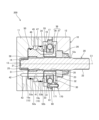
- FIG. 1 is a cross-sectional view of a hydraulic rotating machine according to an embodiment of the present invention.
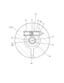
- FIG. 2 is a cross-sectional view taken along line II-II of FIG.
- FIG. 3 is a cross-sectional view taken along line III-III in FIG.
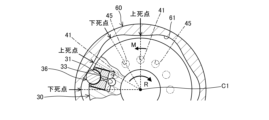
- FIG. 4 is a process sequence diagram showing a state in which the amount of working fluid introduced into the volumetric chamber is at a maximum.
- FIG. 5 is a diagram showing, in a process order, a state in which the amount of working fluid introduced into the volumetric chamber is maximized, and is a diagram showing a state following FIG.
- FIG. 6 is a diagram showing the state when the amount of working fluid introduced into the volumetric chamber is maximized in the order of steps, and is a diagram showing the state following FIG. FIG.
- FIG. 7 is a diagram showing the state when the amount of working fluid guided to the volumetric chamber is maximized in the order of steps, and is a diagram showing the state following FIG.
- FIG. 8 is a diagram showing the state when the amount of working fluid guided to the volumetric chamber is maximized in the order of steps, and is a diagram showing the state following FIG.
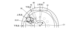
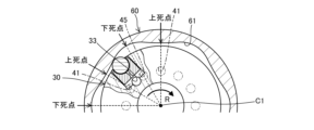
- FIG. 9 is a process sequence diagram showing a state in which the amount of working fluid introduced into the volumetric chamber is minimized.
- FIG. 10 is a diagram showing, in a process order, a state in which the amount of working fluid introduced into the volumetric chamber is minimized, and is a diagram showing a state following FIG. FIG.
- FIG. 11 is a diagram showing the process sequence of the state when the amount of working fluid introduced into the volumetric chamber is minimized, and shows the state following FIG.
- FIG. 12 is a diagram showing the process sequence of the state when the amount of working fluid introduced into the volumetric chamber is minimized, and shows the state following FIG.
- FIG. 13 is a diagram showing, in a process order, a state in which the amount of working fluid introduced into the volumetric chamber is minimized, and shows a state following FIG. 12.
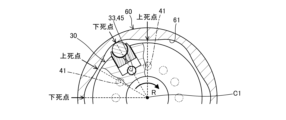
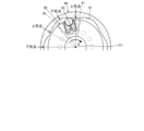
- FIG. 14 is a diagram for explaining when the amount of working fluid guided to the volumetric chamber is maximum and when the amount of working fluid guided to the volumetric chamber is minimum.
- FIG. 15 is a cross-sectional view of a modified example of the hydraulic rotating machine according to the embodiment of the present invention.
- the hydraulic rotating machine is a variable displacement radial piston pump motor 100, which functions as a pump capable of supplying a working fluid by rotating the shaft 20 with external power and reciprocating the piston 36, and also functions as a motor capable of outputting a rotational driving force by rotating the shaft 20 with the piston 36 reciprocating due to the fluid pressure of the working fluid supplied from the outside.
- the working fluid may be water, oil, a water-soluble alternative liquid, or the like, but is not limited to these.
- FIG. 1 is a cross-sectional view showing a cross section of the radial piston pump motor 100
- FIG. 2 is a cross-sectional view taken along line II-II in FIG. 1
- FIG. 3 is a cross-sectional view taken along line III-III in FIG. 1.
- the pump 100 is mounted on a vehicle such as a construction machine, and is used as a working fluid supply source that supplies working fluid to a fluid pressure actuator, etc., by driving the shaft 20 to rotate using the power of an engine or electric motor mounted on the vehicle.
- the pump 100 includes a housing 10, a shaft 20 rotatably supported by the housing 10, a cylinder block 30 housed within the housing 10 and rotating together with the shaft 20 about a central axis of rotation C1, a plurality of cylinders 31 formed in the cylinder block 30, a plurality of pistons 36 slidably inserted into the cylinders 31 and each defining a volume chamber 32 inside the cylinder 31, a port block 50 having a suction port 41 as a first port through which the working fluid supplied to the volume chamber 32 flows and a discharge port 45 as a second port through which the working fluid discharged from the volume chamber 32 flows, and a cam ring 60 having a cam surface 61 with which the piston 36 comes into contact as the cylinder block 30 rotates.
- the housing 10 has a housing body 11 in which a receiving recess 13 is formed to receive the shaft 20, the cylinder block 30, the port block 50, and the cam ring 60, and a housing cover 12 that seals the open end of the housing body 11 and has a through hole 12a through which the shaft 20 is inserted.
- a first accommodating recess 14 that accommodates the tip 21 of the shaft 20 a second accommodating recess 15 that accommodates the port block 50, a third accommodating recess 16 that accommodates the cylinder block 30, and a fourth accommodating recess 17 that accommodates the cam ring 60 are provided in this order from the bottom side of the accommodating recess 13 along the direction of the central axis of rotation C1.
- the bottom of the first accommodating recess 14 may not be closed, but may be open to allow an auxiliary pump or a rotation sensor (not shown) to be attached to the tip 21 of the shaft 20.
- the space for accommodating the cylinder block 30 is formed not only on the housing body 11 side, but also on the housing cover 12 side.
- the housing body 11 is formed with a suction passage 43 through which the working fluid supplied from a tank (not shown) or an auxiliary pump (not shown) flows, a connection passage 42 that connects the suction passage 43 to a plurality of suction ports 41 formed in the port block 50, and a discharge passage 47 through which the working fluid discharged from the volume chamber 32 flows toward a working fluid pressure device (not shown).
- the housing body 11 also has an accommodation section 75 that accommodates a capacity change section 70 (described below).
- the shaft 20 is rotatably supported by the housing body 11 via a first bearing 25 provided in the first accommodating recess 14, and is rotatably supported by the housing cover 12 via a second bearing 26.
- a connecting portion 22 is formed at the end of the shaft 20 that protrudes to the outside through the through hole 12a of the housing cover 12, to which a power source (not shown) that drives the pump 100 is connected.
- a splined shaft portion 23 is formed on the outer circumferential surface of the shaft 20 between the first bearing 25 and the second bearing 26, and is splined to a spline hole portion 35 (described below) formed in the cylinder block 30.
- the cylinder block 30 is an annular member with a through hole in the center through which the shaft 20 passes, and has a number of cylinders 31 formed radially around the central axis of rotation C1, communication holes 33 that can connect the cylinders 31 to the suction port 41 and the discharge port 45, and a spline hole portion 35 formed on the inner surface of the through hole through which the shaft 20 passes.
- FIG. 2 shows an example in which eight cylinders 31 are provided, but the number of cylinders 31 provided is not limited to this, and may be more or less than eight.
- the communication hole 33 is formed along the direction of the central axis of rotation C1 so that one end opens at the bottom of the cylinder 31 and the other end opens at a sliding surface 34 formed on the side of the cylinder block 30.
- the sliding surface 34 where the communication hole 33 opens is the surface that comes into sliding contact with a sliding surface 55 (described below) of the port block 50 when the cylinder block 30 rotates.
- the piston 36 has a columnar portion 37 that is inserted into the cylinder 31, and a sphere 38 provided at the end of the columnar portion 37.
- a hole formed in a concave spherical shape to hold the sphere 38 is formed at one end of the columnar portion 37, and with the sphere 38 more than halfway housed in this hole, the open end of the columnar portion 37 is drawn (crimped) from the radially outside, so that the sphere 38 is rotatably held by the columnar portion 37.
- the piston 36 is also configured to be able to supply the working fluid in the volume chamber 32 to the surface of the sphere 38 as a lubricant.
- the sphere 38 located at the very tip of the piston 36 protruding from the open end of the cylinder 31 is pressed against the cam surface 61 of the cam ring 60. Therefore, the sphere 38 functions as a transmission part that reciprocates the piston 36 in accordance with the profile of the cam surface 61.
- a spring that biases the piston 36 radially outward may be installed inside the cylinder 31 to keep the sphere 38 constantly pressed against the cam surface 61 of the cam ring 60.
- the cam ring 60 is an annular member having a cam surface 61 formed on its inner peripheral surface, and is sandwiched between the housing body 11 and the housing cover 12 when the housing cover 12 is attached and fixed to the housing body 11 while it is housed in the fourth housing recess 17.
- the shape of the cam surface 61 in the circumferential direction has a cam profile in which the top dead center, at which the amount of insertion of the piston 36 into the cylinder 31 is maximized, and the bottom dead center, at which the amount of insertion of the piston 36 into the cylinder 31 is minimized, are alternately provided.
- the surface of the cam surface 61 has an arc-shaped groove formed in the circumferential direction to match the curvature of the sphere 38. Therefore, the sphere 38, which is rotatably mounted on the piston 36, moves smoothly while rolling on the cam surface 61 without coming off the cam surface 61.
- the shape of the piston 36 in contact with the cam surface 61 is not limited to the sphere 38 as described above, and may be, for example, a convex spherical portion formed directly on the end of the columnar portion 37, or a cylinder rotatably held by the columnar portion 37.
- a sphere 38 as described above is preferable.
- the port block 50 is a cylindrical member having a through hole 51 through which the shaft 20 passes, a sliding surface 55 that is in surface contact with the sliding surface 34 of the cylinder block 30, and a number of suction ports 41 and discharge ports 45 that open at one end on the sliding surface 55.
- the port block 50 is pressed toward the cylinder block 30 by the biasing force of a spring 58 arranged in the accommodation recess 13 so that the sliding surface 55 where the suction port 41 and the discharge port 45 open is always in surface contact with the sliding surface 34 of the cylinder block 30.
- the port block 50 is arranged in the housing 10 so as to be in sliding contact with the rotating cylinder block 30.
- the second accommodating recess 15 in which the port block 50 is accommodated is composed of a small diameter recess 15a and a large diameter recess 15b whose inner diameter is larger than that of the small diameter recess 15a.
- the port block 50 is provided with a small diameter portion 52a that is accommodated in the small diameter recess 15a, and a large diameter portion 52b whose outer diameter is larger than that of the small diameter portion 52a and that is accommodated in the large diameter recess 15b.
- an annular space 46 communicating with the discharge passage 47 is formed.
- an O-ring 53a provided on the small diameter portion 52a and an O-ring 53b provided on the large diameter portion 52b prevent the working fluid from flowing into the annular space 46 and the working fluid from flowing out of the annular space 46 through the gap between the small diameter recess 15a and the small diameter portion 52a and the gap between the large diameter recess 15b and the large diameter portion 52b.
- the suction ports 41 are formed in the port block 50 in such a way that one end opens at the sliding surface 55 and the other end connects to the connecting passage 42, and the discharge ports 45 are formed in the port block 50 in such a way that one end opens at the sliding surface 55 and the other end opens in the annular space 46.
- the opening positions of the suction ports 41 and the discharge ports 45 on the sliding surface 55 are set to be alternately positioned at equal intervals in the circumferential direction.
- the suction ports 41 and the discharge ports 45 are arranged to alternately communicate with the communication holes 33 as the cylinder block 30 rotates.
- the suction ports 41 are shown by dashed lines
- the discharge ports 45 are shown by dashed lines. Note that in FIG. 2, some of the suction ports 41 and discharge ports 45 overlap with the communication holes 33.
- connection passage 42 to which the other end of the suction port 41 is connected is not formed in a ring shape as shown in FIG. 3. For this reason, some of the suction ports 41 are formed in a three-dimensional bent shape within the port block 50. Also, as described below, the opening position of the other end of each suction port 41 is appropriately set according to the maximum amount of rotation of the port block 50 so that the other end of the suction port 41 remains connected to the connection passage 42 even when the port block 50 rotates around the central axis of rotation C1.
- the pump 100 configured as described above further includes a capacity change unit 70 that changes the amount of working fluid introduced into each volume chamber 32 as a mechanism for varying the discharge volume.
- the capacity change unit 70 shown in Figures 1 and 3 changes the relative positional relationship between the port block 50 and the cam ring 60 around the rotation center axis C1 by rotating the port block 50 around the rotation center axis C1, and more specifically, changes the positions of the suction port 41 and the discharge port 45 relative to the cam surface 61 around the rotation center axis C1.
- the capacity change unit 70 may also rotate the cam ring 60 around the rotation center axis C1, as described below.
- the capacity change section 70 has a rod-shaped control pin 71, one end of which is rotatably inserted into a hole formed in the end face of the small diameter section 52a of the port block 50, a control piston 72 that can press the control pin 71 in a direction perpendicular to the central axis of rotation C1, a control pressure chamber 73 formed on the opposite side of the control piston 72 from the control pin 71, and a control spring 74 that biases the control pin 71 toward the control piston 72.
- the control pin 71 is installed so that its tip passes through a first housing hole 75a formed from the bottom of the second housing recess 15 along the direction of the central axis of rotation C1, and enters a second housing hole 75b that houses the control piston 72 and the control spring 74.
- the second housing hole 75b is formed along a direction perpendicular to the central axis of rotation C1, as shown in FIG. 3.
- the tip portion of the control pin 71 that protrudes into the second receiving hole 75b has a shape with two parallel flat surfaces, with the pressing force of the control piston 72 acting on one flat surface and the biasing force of the control spring 74 acting on the other flat surface.
- the pressing force of the control piston 72 and the biasing force of the control spring 74 act on the port block 50 via the control pin 71.
- the capacity change unit 70 further includes a control valve (not shown) that controls the flow of working fluid into and out of the control pressure chamber 73.
- the control pin 71 moves in a direction that contracts the control pressure chamber 73 due to the biasing force of the control spring 74.
- the port block 50 rotates around the central axis of rotation C1 in the direction in which the control pin 71 moves.
- control piston 72, control pressure chamber 73, and control spring 74 function as a load applying section that applies a load to the port block 50 via the control pin 71 to rotate the port block 50 around the central axis of rotation C1, and the amount of rotation of the port block 50 can be adjusted to any desired amount by changing the pressure of the working fluid supplied to the control pressure chamber 73.
- the maximum rotation amount of the port block 50 required to change the amount of working fluid led to the volume chamber 32 (maximum required rotation angle) is approximately 15°.
- the maximum rotation amount of the port block 50 i.e., the maximum movement amount (maximum required stroke) of the control piston 72 that rotates the port block 50 via the control pin 71, becomes larger the fewer the number of times the piston 36 reciprocates during one rotation of the cylinder block 30, and becomes smaller the more the number of times the piston 36 reciprocates during one rotation of the cylinder block 30.
- the load applying unit that applies the load to the port block 50 via the control pin 71 to rotate the port block 50 is not limited to the above-mentioned one that uses the pressure of the fluid supplied to the control pressure chamber 73 or the biasing force of the control spring 74, and may be, for example, an electric linear actuator that can move the control pin 71 along a direction perpendicular to the central axis of rotation C1.
- the rotation mechanism that rotates the port block 50 is not limited to the above-mentioned configuration, and may be any mechanism that can rotate the port block 50 a predetermined amount around the central axis of rotation C1, and may be, for example, a mechanism that is composed of a rack gear formed in an arc shape on the small diameter portion 52a of the port block 50, a pinion gear that meshes with the rack gear, and a stepping motor that rotates the pinion gear.
- the capacity change unit 70 is disposed on the opposite side of the port block 50 from the cylinder block 30 in the axial direction of the central axis of rotation C1. Therefore, even if the capacity change unit 70 is provided to make the pump 100 a variable capacity type, it is possible to prevent the pump 100 from becoming too large in the radial direction.
- FIGS. 4 to 13 show a cross section equivalent to the cross section shown in FIG. 2, and FIGS. 4 to 8 show the state in process order when the amount of working fluid led to each volume chamber 32 is at a maximum, and FIGS. 9 to 13 show the state in process order when the amount of working fluid led to each volume chamber 32 is at a minimum. Note that FIGS. 4 to 13 only show the movement of one piston 36 relative to the cam surface 61 of the cam ring 60, but the movement of the other pistons 36 is similar.
- the port block 50 is rotated to a preset position by the capacity change unit 70, so that the suction port 41 and the discharge port 45 are each open at an intermediate position between the top dead center and the bottom dead center of the cam surface 61, as shown in FIG. 4.
- the capacity change unit 70 sets the relative positional relationship between the port block 50 and the cam ring 60 about the rotation central axis C1 so that the suction port 41 is located at the midpoint between the top dead center and the bottom dead center of the cam surface 61, and the discharge port 45 is located at the midpoint between the bottom dead center and the top dead center of the cam surface 61.
- the suction port 41 is located at the midpoint between the top dead center and bottom dead center of the cam surface 61.
- the opening center of the suction port 41 is located on a bisector that equally divides the angle between the line connecting the top dead center of the cam surface 61 and the central axis C1 of rotation and the line connecting the bottom dead center of the cam surface 61 and the central axis C1 of rotation, and the phase difference in the circumferential direction between the suction port 41 and the top dead center is equal to the phase difference in the circumferential direction between the suction port 41 and the bottom dead center.
- the discharge port 45 is located at the midpoint between the bottom dead center and top dead center of the cam surface 61.
- the opening center of the discharge port 45 is located on a bisector that equally divides the angle between the line connecting the bottom dead center of the cam surface 61 and the central axis C1 of rotation and the line connecting the top dead center of the cam surface 61 and the central axis C1 of rotation, and the phase difference in the circumferential direction between the discharge port 45 and the bottom dead center is equal to the phase difference in the circumferential direction between the discharge port 45 and the top dead center.
- the piston 36 which was at top dead center, will begin to move radially outward along the cam surface 61 as soon as the suction process begins.
- the volume chamber 32 begins to expand, and the working fluid is sucked into the volume chamber 32 from the tank (not shown) through the suction port 41, which communicates with the communication hole 33, the connection passage 42, and the suction passage 43.
- the piston 36 which was at the bottom dead center, will begin to move radially inward along the cam surface 61 at the same time that the discharge process begins.
- the volume chamber 32 begins to contract, and the working fluid in the volume chamber 32 is discharged through the discharge port 45, which communicates with the communication hole 33, the annular space 46, and the discharge passage 47 to a working fluid pressure device (not shown).
- the port block 50 is rotated to a preset position by the capacity change unit 70, so that the suction port 41 is positioned at the same position as the top dead center of the cam surface 61 in the circumferential direction, and the discharge port 45 is positioned at the same position as the bottom dead center of the cam surface 61 in the circumferential direction, as shown in FIG. 9.
- the capacity change unit 70 rotates the port block 50 by a predetermined angle (e.g., 15°) about the central axis of rotation C1 in the direction indicated by arrow M in FIG. 9 (the opposite direction to arrow R) from the state shown in FIG.
- a predetermined angle e.g. 15°
- the suction port 41 is located at the same position in the circumferential direction as the top dead center of the cam surface 61" means that the opening center of the suction port 41 is located on the line connecting the top dead center of the cam surface 61 and the central axis of rotation C1
- the discharge port 45 is located at the same position in the circumferential direction as the bottom dead center of the cam surface 61” means that the opening center of the discharge port 45 is located on the line connecting the bottom dead center of the cam surface 61 and the central axis of rotation C1.
- working fluid is discharged from the volume chamber 32 from when the communication hole 33 and the suction port 41 start to communicate with each other while the piston 36 is moving toward the top dead center until the piston 36 reaches the top dead center as shown in FIG. 10, and working fluid is sucked into the volume chamber 32 from when the communication hole 33 and the suction port 41 are connected with each other while the piston 36 starts to move toward the bottom dead center until the communication between the communication hole 33 and the suction port 41 is cut off as shown in FIG. 11.
- working fluid is sucked into the volume chamber 32 from when the communication hole 33 and the discharge port 45 start to communicate with each other while the piston 36 is moving toward the bottom dead center until the piston 36 reaches the bottom dead center as shown in FIG. 12, and working fluid is discharged from the volume chamber 32 from when the communication hole 33 and the discharge port 45 start to communicate with each other while the piston 36 starts to move toward the top dead center until the communication between the communication hole 33 and the discharge port 45 is cut off as shown in FIG. 13.
- the same amount of working fluid is discharged from the volume chamber 32 through the discharge port 45 as was sucked into the volume chamber 32 through the discharge port 45, so the actual discharge amount from the volume chamber 32 is zero.
- the suction port 41 opens at the same position in the circumferential direction as the top dead center of the cam surface 61
- the discharge port 45 opens at the same position in the circumferential direction as the bottom dead center of the cam surface 61
- the amount of working fluid sucked into the volume chamber 32 through the suction port 41 during the suction stroke is substantially zero
- the amount of working fluid discharged from the volume chamber 32 through the discharge port 45 during the discharge stroke is also substantially zero.
- the discharge volume of the pump 100 is substantially zero, i.e., at a minimum.
- the amount of working fluid discharged from each volume chamber 32 varies depending on how two periods overlap with each other: a contraction period during which the volume of the volume chamber 32 contracts, i.e., the period during which the piston 36 moves from the bottom dead center toward the top dead center, and an expansion period during which the volume of the volume chamber 32 expands, i.e., the period during which the piston 36 moves from the top dead center toward the bottom dead center, a suction period during which the communication hole 33 and the suction port 41 communicate and the working fluid can be sucked into the volume chamber 32, i.e., a supply period during which the communication hole 33 and the discharge port 45 communicate and the working fluid in the volume chamber 32 can be discharged.
- a contraction period during which the volume of the volume chamber 32 contracts i.e., the period during which the piston 36 moves from the bottom dead center toward the top dead center
- an expansion period during which the volume of the volume chamber 32 expands i.e., the period during which the piston 36 moves from the top dead center toward the bottom dead center
- the suction period corresponds to the period of the suction process described above, and can also be said to be a communication state period during which the communication hole 33 and the suction port 41 are in communication.
- the dischargeable period corresponds to the period of the discharge process described above, and can also be considered a communication state period during which the communication hole 33 and the discharge port 45 are in communication.
- the suction port 41 and the discharge port 45 are each open at an intermediate position between the top dead center and the bottom dead center of the cam surface 61, so that the suction period overlaps with the expansion period, and the discharge period overlaps with the contraction period.
- the suction port 41 opens at a position in the circumferential direction that is the same as the top dead center of the cam surface 61
- the discharge port 45 opens at a position in the circumferential direction that is the same as the bottom dead center of the cam surface 61.
- the amount of working fluid discharged from the volume chamber 32 through the suction port 41 during the suction possible period and the amount of working fluid sucked into the volume chamber 32 through the suction port 41 are approximately the same, and as a result, the amount of working fluid discharged from each volume chamber 32 is substantially zero, i.e., minimal.
- the amount of working fluid discharged from each volume chamber 32 is maximized by making the first period T1 in which the suction possible period and the contraction period overlap zero or close to zero, i.e., by making the ratio of the first period T1 and the second period T2 0:100.
- the suction port 41 and the discharge port 45 are open between the position shown in FIG. 4 and the position shown in FIG. 9, during the suction process, the working fluid is discharged from the volume chamber 32, but the amount discharged from the volume chamber 32 through the suction port 41 is less than the amount sucked into the volume chamber 32 through the suction port 41, and during the discharge process, the working fluid is sucked into the volume chamber 32, but the amount sucked into the volume chamber 32 through the discharge port 45 is less than the amount discharged from the volume chamber 32 through the discharge port 45.
- the amount of working fluid discharged from each volume chamber 32 changes by changing the position at which the suction port 41 and the discharge port 45 open between the position shown in FIG. 4 and the position shown in FIG. 9, and decreases as the circumferential phase difference between the top dead center and the suction port 41 is reduced and the circumferential phase difference between the bottom dead center and the discharge port 45 is reduced, i.e., the above-mentioned first period T1 during which the suction period and the contraction period overlap is lengthened.
- the circumferential phase difference between the top dead center and the suction port 41 becomes smaller means that the opening center of the suction port 41 is moved closer to the line connecting the top dead center of the cam surface 61 and the central axis of rotation C1, thereby reducing the circumferential difference between the position of the top dead center and the position of the suction port 41; and "the circumferential phase difference between the bottom dead center and the discharge port 45 becomes smaller” means that the opening center of the discharge port 45 is moved closer to the line connecting the bottom dead center of the cam surface 61 and the central axis of rotation C1, thereby reducing the circumferential difference between the position of the bottom dead center and the position of the discharge port 45.
- the port block 50 by rotating the port block 50 around the central axis of rotation C1 using the capacity changing unit 70 and appropriately changing the magnitude of the phase difference between the top dead center and the suction port 41 and the phase difference between the bottom dead center and the discharge port 45, that is, by appropriately changing the ratio between the first period T1 in which the suction possible period and the contraction period overlap and the second period T2 in which the suction possible period and the expansion period overlap, the amount of working fluid guided to each volume chamber 32 can be easily increased or decreased.
- the position of the port block 50 can be appropriately changed between a maximum position when the discharge rate is maximum and a minimum position when the discharge rate is minimum, thereby adjusting the discharge rate of the pump 100 to a desired amount.
- the discharge rate of the pump 100 can be set to approximately 50% of the maximum discharge rate.
- the amount of working fluid guided to each volume chamber 32 i.e., the discharge volume of the pump 100, can be changed by rotating the port block 50 around the central axis of rotation C1 and changing the relative positional relationship between the port block 50 and the cam ring 60.
- variable displacement pump 100 it is only necessary to rotate the port block 50 about the central axis of rotation C1, and since there is no need to move any parts along the direction of the central axis of rotation C1 or along the radial direction, there is no need to secure space to allow movement of parts in the axial and radial directions. This allows the variable displacement pump 100 to be made compact.
- the relative positional relationship between the port block 50 and the cam ring 60 is changed by rotating the port block 50 around the central axis of rotation C1.
- the relative positional relationship between the port block 50 and the cam ring 60 may be changed by rotating the cam ring 60 around the central axis of rotation C1, as in the modified example shown in FIG. 15.
- the capacity change unit 170 has a control pin 171, one end of which is rotatably inserted into a hole formed in the side of the cam ring 60, and a load application unit (not shown) that applies a load to the cam ring 60 via the control pin 171 to rotate the cam ring 60 around the rotation center axis C1.
- the cam ring 60 is rotated by applying the pressing force of a control piston (not shown) or the biasing force of a control spring (not shown) that functions as a load application unit to the control pin 171.
- variable displacement pump 200 can be made compact.
- the capacity change unit 170 of this modified example is disposed on the opposite side of the cam ring 60 from the sliding surfaces 34, 55 between the cylinder block 30 and the port block 50 in the axial direction of the central axis of rotation C1. Therefore, even if the capacity change unit 170 is provided to make the pump 200 a variable capacity type, it is possible to prevent the pump 200 from becoming too large in the radial direction.
- the amount of working fluid guided to each volume chamber 32 is reduced by moving the suction port 41 from an intermediate position between the top dead center and bottom dead center of the cam surface 61 toward the top dead center side, and moving the discharge port 45 from an intermediate position between the bottom dead center and top dead center of the cam surface 61 toward the bottom dead center side.
- the amount of working fluid guided to each volume chamber 32 may be reduced by moving the suction port 41 from the intermediate position toward the bottom dead center side instead of the top dead center side, and moving the discharge port 45 from the intermediate position toward the top dead center side instead of the bottom dead center side.
- the discharge port 45 opens at the same position in the circumferential direction as the top dead center of the cam surface 61
- the amount of working fluid sucked into the volume chamber 32 through the suction port 41 during the suction stroke is substantially zero
- the amount of working fluid discharged from the volume chamber 32 through the discharge port 45 during the discharge stroke is also substantially zero.
- the discharge volume of the pump 100 is substantially zero, i.e., at a minimum.
- the amount of working fluid discharged from each volume chamber 32 decreases as the circumferential phase difference between the bottom dead center and the suction port 41 is reduced and the circumferential phase difference between the top dead center and the discharge port 45 is reduced, i.e., the period during which the suction period and the contraction period overlap is lengthened.
- the capacity change unit 70 rotates the port block 50 around the central axis of rotation C1 in the direction opposite to the arrow M in FIG. 9, and the magnitude of the phase difference between the bottom dead center and the suction port 41 and the phase difference between the top dead center and the discharge port 45 are appropriately changed, the amount of working fluid guided to each volume chamber 32 can be easily increased or decreased, just like in the above embodiment.
- the radial piston pump motor 100 functions as a pump, but the radial piston pump motor 100 may also function as a motor.
- the first port 41 serves as a supply port that supplies pressurized working fluid to the volume chamber 32
- the second port 45 serves as a discharge port that discharges the working fluid from the volume chamber 32 to a tank.
- the output of the radial piston pump motor 100 when it functions as a motor can be adjusted by changing the relative positional relationship between the port block 50 and the cam ring 60, as in the above embodiment.
- the period during which the communication hole 33 and the supply port (first port 41) communicate with each other and the pressurized working fluid can be supplied to the volume chamber 32 corresponds to the suction period in the above embodiment, that is, the supply period during which the working fluid can be supplied to the volume chamber 32.
- the cross-sectional shapes of the communication hole 33, the suction port 41, and the discharge port 45 are circular, but these cross-sectional shapes are not limited to circular and may be, for example, elliptical or rectangular.
- the communication hole 33 opens at the center of the volume chamber 32, but the communication hole 33 may open at a location offset from the center of the volume chamber 32. Even if the communication hole 33 does not open at the center of the volume chamber 32 in this way, as described above, it is possible to increase or decrease the amount of working fluid guided to each volume chamber 32 by changing the ratio between the first period T1 in which the contraction period and the suction-enabled period overlap and the second period T2 in which the expansion period and the suction-enabled period overlap.
- the radial piston pump motor 100, 200 comprises a housing 10, a cylinder block 30 accommodated within the housing 10 and rotating with the shaft 20, a number of cylinders 31 formed in the cylinder block 30 radially around the central axis C1 of rotation of the shaft 20, a number of pistons 36 slidably inserted into the cylinders 31 and each defining a volume chamber 32 inside the cylinder 31, a suction port 41 (first port) through which the working fluid supplied to the volume chamber 32 flows, and a piston 36 (second port) through which the working fluid discharged from the volume chamber 32 flows.
- the port block 50 has a discharge port 45 (second port) and is disposed in the housing 10 so as to be in sliding contact with the cylinder block 30; the cam ring 60 has a cam surface 61 with which the tip of the piston 36 comes into contact as the cylinder block 30 rotates; and the capacity change unit 70, 170 changes the amount of working fluid led to the volume chamber 32 by rotating at least one of the port block 50 and the cam ring 60 about the central axis of rotation C1 to change the relative positional relationship between the port block 50 and the cam ring 60.
- the amount of working fluid guided to each volume chamber 32 can be changed by rotating at least one of the port block 50 and the cam ring 60 around the central axis of rotation C1 and changing the relative positional relationship between the port block 50 and the cam ring 60.
- the capacity change unit 70, 170 is a mechanism that rotates either the port block 50 or the cam ring 60 around the central axis of rotation C1, and is positioned on the opposite side of the sliding surfaces 34, 55 between the cylinder block 30 and the port block 50, sandwiching either the port block 50 or the cam ring 60 in the axial direction of the central axis of rotation C1.
- the capacity change unit 70 that rotates the port block 50 around the rotation center axis C1 is not disposed radially outside the port block 50 or radially outside the cam ring 60, but is disposed on the opposite side of the sliding surfaces 34, 55 between the cylinder block 30 and the port block 50 in the axial direction of the rotation center axis C1, sandwiching the port block 50.
- the capacity change unit 170 that rotates the cam ring 60 around the rotation center axis C1 is not disposed radially outside the cam ring 60, but is disposed on the opposite side of the sliding surfaces 34, 55 between the cylinder block 30 and the port block 50 in the axial direction of the rotation center axis C1, sandwiching the cam ring 60. This makes it possible to prevent the variable capacity radial piston pump motor 100, 200 from becoming larger radially outward.
- the capacity change unit 70, 170 also has a control pin 71, 171 with one end inserted into the port block 50 or cam ring 60, and a load application unit that applies a load to the port block 50 or cam ring 60 via the control pin 71, 171 to rotate the port block 50 or cam ring 60 into which the control pin 71, 171 is inserted about the central axis of rotation C1.
- the cylinder block 30 also has a communication hole 33 that can connect the cylinder 31 to the suction port 41 (first port) and the discharge port 45 (second port), and the amount of working fluid guided to the volume chamber 32 is changed by changing the ratio between a first period T1 during which the supply period during which the communication hole 33 and the suction port 41 (first port) are connected overlaps with a contraction period during which the volume of the volume chamber 32 contracts, and a second period T2 during which the supply period overlaps with an expansion period during which the volume of the volume chamber 32 expands, by the capacity change unit 70, 170.
- the capacity change unit 70, 170 rotates at least one of the port block 50 and the cam ring 60 around the central axis of rotation C1, and the amount of working fluid guided to each volume chamber 32 can be easily increased or decreased by appropriately changing the ratio between the first period T1 in which the suction period and the contraction period overlap, and the second period T2 in which the suction period and the expansion period overlap.
- the piston 36 also has a sphere 38 that rotates with the rotation of the cylinder block 30 and comes into contact with the cam surface 61, and the surface of the cam surface 61 has an arc-shaped groove formed in the circumferential direction to match the curvature of the sphere 38.
- an arc-shaped groove formed to match the curvature of the sphere 38 provided on the piston 36 is provided along the circumferential direction on the surface of the cam surface 61.
- the sphere 38 provided on the piston 36 moves smoothly while rolling on the cam surface 61 without coming off the cam surface 61. This allows the piston 36 to smoothly reciprocate within the cylinder 31 in accordance with the profile of the cam surface 61.
Landscapes
- Engineering & Computer Science (AREA)
- Mechanical Engineering (AREA)
- General Engineering & Computer Science (AREA)
- Chemical & Material Sciences (AREA)
- Combustion & Propulsion (AREA)
- Reciprocating Pumps (AREA)
Priority Applications (3)
| Application Number | Priority Date | Filing Date | Title |
|---|---|---|---|
| JP2025516747A JPWO2024225114A1 (https=) | 2023-04-28 | 2024-04-16 | |
| CN202480025768.6A CN120958234A (zh) | 2023-04-28 | 2024-04-16 | 液压旋转机 |
| EP24796867.0A EP4703587A1 (en) | 2023-04-28 | 2024-04-16 | Hydraulic rotary machine |
Applications Claiming Priority (2)
| Application Number | Priority Date | Filing Date | Title |
|---|---|---|---|
| JP2023074501 | 2023-04-28 | ||
| JP2023-074501 | 2023-04-28 |
Publications (1)
| Publication Number | Publication Date |
|---|---|
| WO2024225114A1 true WO2024225114A1 (ja) | 2024-10-31 |
Family
ID=93256514
Family Applications (1)
| Application Number | Title | Priority Date | Filing Date |
|---|---|---|---|
| PCT/JP2024/015129 Ceased WO2024225114A1 (ja) | 2023-04-28 | 2024-04-16 | 液圧回転機 |
Country Status (4)
| Country | Link |
|---|---|
| EP (1) | EP4703587A1 (https=) |
| JP (1) | JPWO2024225114A1 (https=) |
| CN (1) | CN120958234A (https=) |
| WO (1) | WO2024225114A1 (https=) |
Citations (3)
| Publication number | Priority date | Publication date | Assignee | Title |
|---|---|---|---|---|
| JPS4820082Y1 (https=) * | 1970-09-24 | 1973-06-09 | ||
| JP2009121420A (ja) | 2007-11-16 | 2009-06-04 | Toyota Motor Corp | ラジアルピストンポンプおよびラジアルピストンモータ |
| JP2023074501A (ja) | 2021-11-17 | 2023-05-29 | シァメン ホンファ エレクトリック パワー コントロールズ カンパニー リミテッド | 絶縁能力を向上することができる高電圧直流リレー |
-
2024
- 2024-04-16 EP EP24796867.0A patent/EP4703587A1/en active Pending
- 2024-04-16 WO PCT/JP2024/015129 patent/WO2024225114A1/ja not_active Ceased
- 2024-04-16 CN CN202480025768.6A patent/CN120958234A/zh active Pending
- 2024-04-16 JP JP2025516747A patent/JPWO2024225114A1/ja active Pending
Patent Citations (3)
| Publication number | Priority date | Publication date | Assignee | Title |
|---|---|---|---|---|
| JPS4820082Y1 (https=) * | 1970-09-24 | 1973-06-09 | ||
| JP2009121420A (ja) | 2007-11-16 | 2009-06-04 | Toyota Motor Corp | ラジアルピストンポンプおよびラジアルピストンモータ |
| JP2023074501A (ja) | 2021-11-17 | 2023-05-29 | シァメン ホンファ エレクトリック パワー コントロールズ カンパニー リミテッド | 絶縁能力を向上することができる高電圧直流リレー |
Also Published As
| Publication number | Publication date |
|---|---|
| EP4703587A1 (en) | 2026-03-04 |
| JPWO2024225114A1 (https=) | 2024-10-31 |
| CN120958234A (zh) | 2025-11-14 |
Similar Documents
| Publication | Publication Date | Title |
|---|---|---|
| US8074558B2 (en) | Axial piston device having rotary displacement control | |
| CN101680435B (zh) | 对置式斜板型活塞泵和活塞式液压马达的组装体 | |
| CA2588811C (en) | Variable capacity gerotor pump | |
| JP6993950B2 (ja) | 液圧回転機 | |
| US9133830B2 (en) | Fluid device with flexible ring | |
| US11674505B2 (en) | Swash-plate type piston pump | |
| WO2014156548A1 (ja) | 液圧回転機 | |
| JP5393815B2 (ja) | 流体圧機械 | |
| WO2024225114A1 (ja) | 液圧回転機 | |
| JPH0343680A (ja) | 水圧式変位機械 | |
| CN222046310U (zh) | 调零装置和可变排量液压单元 | |
| KR101582615B1 (ko) | 가변 베인 펌프 | |
| KR102715433B1 (ko) | 유체 기계 및 건설 기계 | |
| US6832903B2 (en) | Functionalties of axially movable spool valve | |
| US8052401B2 (en) | Double-acting radial piston hydraulic apparatus | |
| JP3569759B2 (ja) | 可変容量型斜板式液圧機械 | |
| JP7809003B2 (ja) | 回転斜板式液圧ポンプ | |
| JP3607306B2 (ja) | 可変容量形ポンプ | |
| JP7809002B2 (ja) | 回転斜板式液圧ポンプ | |
| CN222067041U (zh) | 活塞组件和可变排量液压单元 | |
| US8302525B2 (en) | Hydraulic stepless transmission | |
| WO2023189944A1 (ja) | 回転斜板式液圧ポンプ | |
| JP2002276560A (ja) | 液圧パワーパッケージ |
Legal Events
| Date | Code | Title | Description |
|---|---|---|---|
| 121 | Ep: the epo has been informed by wipo that ep was designated in this application |
Ref document number: 24796867 Country of ref document: EP Kind code of ref document: A1 |
|
| WWE | Wipo information: entry into national phase |
Ref document number: 2025516747 Country of ref document: JP |
|
| WWE | Wipo information: entry into national phase |
Ref document number: 2024796867 Country of ref document: EP |
|
| NENP | Non-entry into the national phase |
Ref country code: DE |
|
| ENP | Entry into the national phase |
Ref document number: 2024796867 Country of ref document: EP Effective date: 20251128 |
|
| ENP | Entry into the national phase |
Ref document number: 2024796867 Country of ref document: EP Effective date: 20251128 |
|
| ENP | Entry into the national phase |
Ref document number: 2024796867 Country of ref document: EP Effective date: 20251128 |
|
| ENP | Entry into the national phase |
Ref document number: 2024796867 Country of ref document: EP Effective date: 20251128 |
|
| ENP | Entry into the national phase |
Ref document number: 2024796867 Country of ref document: EP Effective date: 20251128 |
|
| ENP | Entry into the national phase |
Ref document number: 2024796867 Country of ref document: EP Effective date: 20251128 |
|
| ENP | Entry into the national phase |
Ref document number: 2024796867 Country of ref document: EP Effective date: 20251128 |
|
| ENP | Entry into the national phase |
Ref document number: 2024796867 Country of ref document: EP Effective date: 20251128 |
|
| ENP | Entry into the national phase |
Ref document number: 2024796867 Country of ref document: EP Effective date: 20251128 |
|
| WWP | Wipo information: published in national office |
Ref document number: 2024796867 Country of ref document: EP |