WO2024225009A1 - 撮像装置、表示制御方法、プログラム - Google Patents
撮像装置、表示制御方法、プログラム Download PDFInfo
- Publication number
- WO2024225009A1 WO2024225009A1 PCT/JP2024/014284 JP2024014284W WO2024225009A1 WO 2024225009 A1 WO2024225009 A1 WO 2024225009A1 JP 2024014284 W JP2024014284 W JP 2024014284W WO 2024225009 A1 WO2024225009 A1 WO 2024225009A1
- Authority
- WO
- WIPO (PCT)
- Prior art keywords
- lens
- display
- indicator
- imaging device
- control unit
- Prior art date
- Legal status (The legal status is an assumption and is not a legal conclusion. Google has not performed a legal analysis and makes no representation as to the accuracy of the status listed.)
- Ceased
Links
Images












Classifications
-
- H—ELECTRICITY
- H04—ELECTRIC COMMUNICATION TECHNIQUE
- H04N—PICTORIAL COMMUNICATION, e.g. TELEVISION
- H04N23/00—Cameras or camera modules comprising electronic image sensors; Control thereof
- H04N23/60—Control of cameras or camera modules
- H04N23/63—Control of cameras or camera modules by using electronic viewfinders
- H04N23/633—Control of cameras or camera modules by using electronic viewfinders for displaying additional information relating to control or operation of the camera
-
- G—PHYSICS
- G03—PHOTOGRAPHY; CINEMATOGRAPHY; ANALOGOUS TECHNIQUES USING WAVES OTHER THAN OPTICAL WAVES; ELECTROGRAPHY; HOLOGRAPHY
- G03B—APPARATUS OR ARRANGEMENTS FOR TAKING PHOTOGRAPHS OR FOR PROJECTING OR VIEWING THEM; APPARATUS OR ARRANGEMENTS EMPLOYING ANALOGOUS TECHNIQUES USING WAVES OTHER THAN OPTICAL WAVES; ACCESSORIES THEREFOR
- G03B17/00—Details of cameras or camera bodies; Accessories therefor
- G03B17/18—Signals indicating condition of a camera member or suitability of light
- G03B17/20—Signals indicating condition of a camera member or suitability of light visible in viewfinder
-
- G—PHYSICS
- G03—PHOTOGRAPHY; CINEMATOGRAPHY; ANALOGOUS TECHNIQUES USING WAVES OTHER THAN OPTICAL WAVES; ELECTROGRAPHY; HOLOGRAPHY
- G03B—APPARATUS OR ARRANGEMENTS FOR TAKING PHOTOGRAPHS OR FOR PROJECTING OR VIEWING THEM; APPARATUS OR ARRANGEMENTS EMPLOYING ANALOGOUS TECHNIQUES USING WAVES OTHER THAN OPTICAL WAVES; ACCESSORIES THEREFOR
- G03B19/00—Cameras
- G03B19/02—Still-picture cameras
- G03B19/04—Roll-film cameras
- G03B19/07—Roll-film cameras having more than one objective
-
- G—PHYSICS
- G06—COMPUTING OR CALCULATING; COUNTING
- G06F—ELECTRIC DIGITAL DATA PROCESSING
- G06F1/00—Details not covered by groups G06F3/00 - G06F13/00 and G06F21/00
- G06F1/16—Constructional details or arrangements
- G06F1/1613—Constructional details or arrangements for portable computers
- G06F1/1633—Constructional details or arrangements of portable computers not specific to the type of enclosures covered by groups G06F1/1615 - G06F1/1626
- G06F1/1684—Constructional details or arrangements related to integrated I/O peripherals not covered by groups G06F1/1635 - G06F1/1675
- G06F1/1686—Constructional details or arrangements related to integrated I/O peripherals not covered by groups G06F1/1635 - G06F1/1675 the I/O peripheral being an integrated camera
-
- G—PHYSICS
- G06—COMPUTING OR CALCULATING; COUNTING
- G06F—ELECTRIC DIGITAL DATA PROCESSING
- G06F3/00—Input arrangements for transferring data to be processed into a form capable of being handled by the computer; Output arrangements for transferring data from processing unit to output unit, e.g. interface arrangements
- G06F3/01—Input arrangements or combined input and output arrangements for interaction between user and computer
- G06F3/048—Interaction techniques based on graphical user interfaces [GUI]
- G06F3/0484—Interaction techniques based on graphical user interfaces [GUI] for the control of specific functions or operations, e.g. selecting or manipulating an object, an image or a displayed text element, setting a parameter value or selecting a range
- G06F3/04845—Interaction techniques based on graphical user interfaces [GUI] for the control of specific functions or operations, e.g. selecting or manipulating an object, an image or a displayed text element, setting a parameter value or selecting a range for image manipulation, e.g. dragging, rotation, expansion or change of colour
-
- G—PHYSICS
- G06—COMPUTING OR CALCULATING; COUNTING
- G06F—ELECTRIC DIGITAL DATA PROCESSING
- G06F3/00—Input arrangements for transferring data to be processed into a form capable of being handled by the computer; Output arrangements for transferring data from processing unit to output unit, e.g. interface arrangements
- G06F3/01—Input arrangements or combined input and output arrangements for interaction between user and computer
- G06F3/048—Interaction techniques based on graphical user interfaces [GUI]
- G06F3/0484—Interaction techniques based on graphical user interfaces [GUI] for the control of specific functions or operations, e.g. selecting or manipulating an object, an image or a displayed text element, setting a parameter value or selecting a range
- G06F3/04847—Interaction techniques to control parameter settings, e.g. interaction with sliders or dials
-
- H—ELECTRICITY
- H04—ELECTRIC COMMUNICATION TECHNIQUE
- H04N—PICTORIAL COMMUNICATION, e.g. TELEVISION
- H04N23/00—Cameras or camera modules comprising electronic image sensors; Control thereof
- H04N23/60—Control of cameras or camera modules
- H04N23/62—Control of parameters via user interfaces
-
- H—ELECTRICITY
- H04—ELECTRIC COMMUNICATION TECHNIQUE
- H04N—PICTORIAL COMMUNICATION, e.g. TELEVISION
- H04N23/00—Cameras or camera modules comprising electronic image sensors; Control thereof
- H04N23/60—Control of cameras or camera modules
- H04N23/63—Control of cameras or camera modules by using electronic viewfinders
- H04N23/631—Graphical user interfaces [GUI] specially adapted for controlling image capture or setting capture parameters
-
- H—ELECTRICITY
- H04—ELECTRIC COMMUNICATION TECHNIQUE
- H04N—PICTORIAL COMMUNICATION, e.g. TELEVISION
- H04N23/00—Cameras or camera modules comprising electronic image sensors; Control thereof
- H04N23/60—Control of cameras or camera modules
- H04N23/63—Control of cameras or camera modules by using electronic viewfinders
- H04N23/631—Graphical user interfaces [GUI] specially adapted for controlling image capture or setting capture parameters
- H04N23/632—Graphical user interfaces [GUI] specially adapted for controlling image capture or setting capture parameters for displaying or modifying preview images prior to image capturing, e.g. variety of image resolutions or capturing parameters
-
- H—ELECTRICITY
- H04—ELECTRIC COMMUNICATION TECHNIQUE
- H04N—PICTORIAL COMMUNICATION, e.g. TELEVISION
- H04N23/00—Cameras or camera modules comprising electronic image sensors; Control thereof
- H04N23/60—Control of cameras or camera modules
- H04N23/63—Control of cameras or camera modules by using electronic viewfinders
- H04N23/633—Control of cameras or camera modules by using electronic viewfinders for displaying additional information relating to control or operation of the camera
- H04N23/634—Warning indications
-
- H—ELECTRICITY
- H04—ELECTRIC COMMUNICATION TECHNIQUE
- H04N—PICTORIAL COMMUNICATION, e.g. TELEVISION
- H04N23/00—Cameras or camera modules comprising electronic image sensors; Control thereof
- H04N23/60—Control of cameras or camera modules
- H04N23/63—Control of cameras or camera modules by using electronic viewfinders
- H04N23/633—Control of cameras or camera modules by using electronic viewfinders for displaying additional information relating to control or operation of the camera
- H04N23/635—Region indicators; Field of view indicators
-
- H—ELECTRICITY
- H04—ELECTRIC COMMUNICATION TECHNIQUE
- H04N—PICTORIAL COMMUNICATION, e.g. TELEVISION
- H04N23/00—Cameras or camera modules comprising electronic image sensors; Control thereof
- H04N23/60—Control of cameras or camera modules
- H04N23/64—Computer-aided capture of images, e.g. transfer from script file into camera, check of taken image quality, advice or proposal for image composition or decision on when to take image
-
- H—ELECTRICITY
- H04—ELECTRIC COMMUNICATION TECHNIQUE
- H04N—PICTORIAL COMMUNICATION, e.g. TELEVISION
- H04N23/00—Cameras or camera modules comprising electronic image sensors; Control thereof
- H04N23/60—Control of cameras or camera modules
- H04N23/667—Camera operation mode switching, e.g. between still and video, sport and normal or high- and low-resolution modes
-
- H—ELECTRICITY
- H04—ELECTRIC COMMUNICATION TECHNIQUE
- H04N—PICTORIAL COMMUNICATION, e.g. TELEVISION
- H04N23/00—Cameras or camera modules comprising electronic image sensors; Control thereof
- H04N23/60—Control of cameras or camera modules
- H04N23/69—Control of means for changing angle of the field of view, e.g. optical zoom objectives or electronic zooming
-
- H—ELECTRICITY
- H04—ELECTRIC COMMUNICATION TECHNIQUE
- H04N—PICTORIAL COMMUNICATION, e.g. TELEVISION
- H04N23/00—Cameras or camera modules comprising electronic image sensors; Control thereof
- H04N23/90—Arrangement of cameras or camera modules, e.g. multiple cameras in TV studios or sports stadiums
-
- G—PHYSICS
- G06—COMPUTING OR CALCULATING; COUNTING
- G06F—ELECTRIC DIGITAL DATA PROCESSING
- G06F2203/00—Indexing scheme relating to G06F3/00 - G06F3/048
- G06F2203/048—Indexing scheme relating to G06F3/048
- G06F2203/04803—Split screen, i.e. subdividing the display area or the window area into separate subareas
Definitions
- This technology relates to imaging devices, display control methods, and programs, and in particular to the technical field of the user interface of imaging devices.
- Patent Document 1 listed below discloses an example of a screen displayed when a camera application is running on a smartphone.
- the user When taking a picture using the camera function of a smartphone, the user may look at the display side of the smartphone body and point the lens on the back side of the smartphone at the subject to take the picture.
- the captured monitor image (through image) is displayed on the display, so the user can look at the monitor image to decide on the composition, etc., and operate the shutter.
- This disclosure therefore proposes technology that allows users to easily recognize the lens position.
- the imaging device includes a display provided on a first surface of a housing, a lens for imaging provided on a second surface of the housing that is in a front-back relationship with the first surface, and a control unit that controls displaying an indicator indicating the lens at a position on the display where the lens is projected from the second surface onto the first surface.
- a display provided on a first surface of a housing
- a lens for imaging provided on a second surface of the housing that is in a front-back relationship with the first surface
- a control unit that controls displaying an indicator indicating the lens at a position on the display where the lens is projected from the second surface onto the first surface.
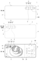
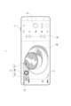
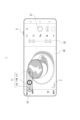
- FIG. 1A and 1B are explanatory diagrams illustrating a display example of an imaging device according to an embodiment of the present technology.
- 5 is an explanatory diagram of a display position of a lens indicator according to an embodiment.
- FIG. This is an explanatory diagram of how the composition changes depending on the lens used.
- 5 is an explanatory diagram of a display position of a lens indicator according to an embodiment.
- FIG. 1 is a block diagram of an imaging apparatus according to an embodiment; 4 is a flowchart of a lens indicator display control according to an embodiment. 4 is a flowchart of a lens indicator display control according to an embodiment. 4 is a flowchart of a lens indicator display control according to an embodiment. 4 is an explanatory diagram of a manipulator for a specific operation according to the embodiment; FIG.
- 5A to 5C are explanatory diagrams of display examples of a lens indicator according to an embodiment.
- 4 is a flowchart of a lens indicator display control according to an embodiment.
- 11 is an explanatory diagram of an example in which a lens indicator display is performed according to an embodiment.
- FIG. 4 is a flowchart of a lens indicator display control according to an embodiment.
- 4 is a flowchart of a lens indicator display control according to an embodiment.
- 5A to 5C are explanatory diagrams of display examples of a lens indicator according to an embodiment.
- FIG. 11 is an explanatory diagram of a lens indicator in which a magnification display is added according to an embodiment.
- 11A to 11C are explanatory diagrams of a slide operation for a lens indicator according to an embodiment.
- 11 is a flowchart of an example of a process for an operation of a lens indicator according to an embodiment.
- 11A and 11B are explanatory diagrams of an operation mode using a display in which a lens indicator and a slider are combined according to an embodiment.
- 5A to 5C are explanatory diagrams of display examples of a lens indicator according to an embodiment.
- 11 is a flowchart of a process for changing a display mode of a lens indicator according to an embodiment.
- FIG. 4 is an explanatory diagram of a background blurring function according to an embodiment.
- Lens indicator display> 2. Imaging device configuration 3. Lens indicator display control process ⁇ 4. Examples of displays and operations> 5. Summary and Modifications
- image refers to both still images and moving images.
- image capture includes both still image capture and moving image capture.
- FIG. 1 shows an example of a display on a first surface 100 of a housing of an imaging device 1 according to an embodiment.
- the imaging device 1 in the embodiment is a smartphone, which is a general-purpose information processing device.
- the smartphone functions as the imaging device 1 when a camera application is launched.
- the housing of the imaging device 1 in the embodiment refers to the housing of a smartphone, for example a housing having a flat, approximately rectangular parallelepiped shape.
- a display 2 is formed on a first surface 100 of the housing, and various images are displayed by the application program that is started.
- a monitor area 20 is provided in a part of the display 2, and a monitor image (through image) of the subject side is displayed here. Also displayed are a still image and video recording button 21, a zoom magnification button 22, a menu button 23, and various other buttons and icons. Depending on the set value of the captured image size (aspect ratio), the entire screen may be used as the monitor area 20 to display the monitor image, and the above-mentioned record button 21, the lens indicator 10 described below, and other icons may be superimposed on the monitor image.
- the user can use the record button 21 to capture still images and start/stop recording moving images.
- a shutter button 3 is provided on the side of the housing. A user can also use the shutter button 3 to take a still image.
- the user can also change the zoom magnification by tapping or sliding the zoom magnification button 22.
- the operation of the zoom magnification includes switching the lens. For example, by selecting the "x0.7" button, the ultra-wide lens 6U is selected.
- the zoom magnification can also be changed by sliding the "x0.7” or "x3.5 x5.2" button. In some cases, the lens may be automatically switched during the slide.
- the above is an example of the zoom magnification operation, but various operation modes are possible using the zoom magnification button 22. For example, by operating any of the zoom magnification buttons 22, icons or sliders of magnifications with different granularity may be displayed, and the user may specify an arbitrary magnification by pinching or the like on the icons or sliders.
- Various operation menus are displayed by the menu button 23.
- the user can make various settings using the operation menu.
- mode settings related to the lens indicator 10, which will be described next, can also be made.
- a lens indicator 10 is displayed on the display 2 .
- position marks 11 (11U, 11W, 11T) indicate the actual position of the lens provided on the second surface 200, which is the reverse side of the first surface 100 on which the display 2 is provided.
- the second surface 200, the second surface 200 viewed from the first surface 100 side, and the first surface 100 are shown for comparison.
- the second surface 200 is the back surface of the smartphone, and has the lens unit 5 disposed thereon.
- the lens unit 5 has, as an example, three lenses 6, such as an ultra-wide lens 6U, a wide lens 6W, and a telephoto lens 6T.
- the lens unit 5 also has a TOF (Time Of Flight) sensor 9 disposed between the wide lens 6W and the telephoto lens 6T.
- the TOF sensor 9 has an exposed light emitting portion and a light receiving portion as shown in the figure. Adjacent to the lens unit 5, there are provided a flash unit 8 and a photometry unit 7 that measures the ambient light.
- the lens unit 5 is disposed in the upper left part of the drawing when viewed from the display 2 side.
- a lens indicator 10 is displayed corresponding to the position of this lens unit 5, and position marks 11U, 11W, and 11T are displayed corresponding to each of the three lenses 6.
- the position mark 11U is displayed at a position where the ultra wide lens 6U is vertically projected from the second surface 200 onto the first surface 100.
- the position mark 11W is displayed at a position where the wide lens 6W is vertically projected from the second surface 200 onto the first surface 100.
- the position mark 11T is displayed at a position where the tele lens 6T is vertically projected from the second surface 200 onto the first surface 100.
- the lens indicator 10 is displayed at the position on the display 2 where each lens 6 is projected from the second surface 200 to the first surface 100, and the position mark 11 shows the user the position of each lens 6 on the back surface of the display 2 that is being viewed. That is, the lens indicator 10 is displayed so that the position mark 11 is located at a position on the display 2 directly behind the arrangement position of each lens 6 .
- the lens indicator 10 allows the user to recognize the position of the lens on the back surface.
- the position mark 11W is displayed in a highlighted manner so as to be more noticeable than the position marks 11U and 11T.
- the position mark 11W is displayed in a high brightness or a specific color. This indicates that the wide lens 6W is currently being used for imaging. That is, the user can recognize the lens currently being used by the difference in the display mode of the position marks 11U, 11W, and 11T.
- FIGs 3A and 3B show an example in which lenses 6a, 6b, and 6c are provided in the lens unit 5, and a captured image.
- the composition of the captured image differs as shown in the figure when shooting with the left lens 6a as in Figure 3A and when shooting with the right lens 6c as in Figure 3B in the same positional relationship.
- the lens position cannot be grasped, the user may not be able to obtain the composition intended by the user even when shooting.
- the lens 6 used in macro photography varies depending on the model and manufacturer, making it difficult for the user to know which lens 6 will be used.
- the lens indicator 10 allows the user to recognize the lens position to be used, which significantly improves usability.
- FIG. 1 and 2 show an example of a smartphone equipped with three lenses 6, but the lens indicator 10 is also useful for a smartphone equipped with one lens 6.
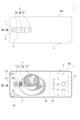
- Fig. 4 shows an example of a smartphone equipped with one lens 6 in a format similar to that of Fig. 2.
- a lens unit 5 having one lens 6 is disposed on the second surface 200.
- the lens indicator 10 and the position mark 11 are displayed at corresponding positions on the first surface 100.
- the composition may not be as desired unless the user is aware of the position of the lens 6. Also, the user may end up placing his/her finger on the surface of the lens 6. Therefore, even if the smartphone is not equipped with multiple lenses, the display of the lens indicator 10 is useful.
- Imaging device configuration An example of the configuration of an imaging device 1 that performs a display including the lens indicator 10 as described above is shown in Fig. 5.
- the imaging device 1 includes a control unit 30, a lens unit 31, a display unit 32, an operation unit 33, a sensor unit 34, a distance measurement unit 35, a storage control unit 36, and a memory unit 37.
- the configuration in Fig. 5 is merely an example showing the main parts, and the imaging device 1 may include components that are not shown, and it is not necessary to include all of the components shown.
- the lens section 31 corresponds to the above-mentioned lens unit 5 and one or more lenses 6 of the lens unit 5, and includes an image sensor that receives incident light, and a processing circuit for processing signals photoelectrically converted by the image sensor.
- the lens unit 5 in the lens section 31 includes optical systems such as a zoom lens, a focus lens, and an aperture mechanism, as well as a drive mechanism for these optical elements.
- the above-mentioned "lens 6" collectively refers to the optical system up to the image sensor. This optical system guides light from the subject and focuses it on the image sensor.
- the image sensor in the lens unit 31 is configured as, for example, a CCD (Charge Coupled Device) type or a CMOS (Complementary Metal Oxide Semiconductor) type.
- the image sensor performs, for example, CDS (Correlated Double Sampling) processing, AGC (Automatic Gain Control) processing, etc. on the electrical signal obtained by photoelectrically converting the received light, and further performs A/D (Analog/Digital) conversion processing.
- the captured image signal is then output as digital data to the control unit 30.
- the display unit 32 is made up of the above-mentioned display 2 and its display drive circuit, and displays various information to the user.
- the display 2 is made up of a liquid crystal panel (LCD: Liquid Crystal Display), an organic EL (Electro-Luminescence) panel, etc.
- This display unit 32 executes various displays on the display screen based on instructions from the control unit 30.
- the display unit 32 displays a monitor image (through image) during shooting, and various icons and controls as a user interface.
- it executes displays as a GUI (Graphical User Interface) on the screen.
- GUI Graphic User Interface
- the operation unit 33 collectively indicates input devices for the user to input various operations, specifically, physical operators such as the shutter button 3, a touch panel provided on the display 2, and the like that detects operations on operators (buttons, icons, sliders, etc.) displayed on the display 2, and the like.
- the operation unit 33 detects the operation of the user, and sends a signal corresponding to the input operation to the control unit 30 .
- the sensor unit 34 indicates various sensors mounted on the imaging device 1 .
- the sensor unit 34 is equipped with, for example, an IMU (inertial measurement unit), and can detect angular velocity using a three-axis angular velocity (gyro) sensor of pitch, yaw, and roll, and can detect acceleration using an acceleration sensor.
- an illuminance sensor constituting the photometry section 7 is mounted.
- Various information detected by the sensor unit 34 is supplied to the control unit 30.
- the distance measurement unit 35 includes a light emitting unit, a light receiving unit, and a calculation control unit that controls the light emission and performs calculations based on the light receiving signal, and performs processing to calculate the distance (depth) to the subject.
- the calculated distance information is supplied to the control unit 30.
- the storage control unit 36 performs processing for recording image files (content files) such as still image data and video data, attribute information of the image files, thumbnail images, and the like, onto a recording medium such as a non-volatile memory.
- image files content files
- the storage control unit 36 may be a circuit unit that performs recording and playback on a flash memory built into the imaging device 1, or a card recording and playback circuit that performs recording and playback access on a memory card (e.g., a portable flash memory) that can be attached to and detached from the imaging device 1.
- the storage control unit 36 may also be realized as a hard disk drive (HDD) or solid state drive (SSD) built into the imaging device 1.
- HDD hard disk drive
- SSD solid state drive
- the control unit 30 is configured by a microcomputer (arithmetic processing device) equipped with a CPU (Central Processing Unit).
- the memory unit 37 stores information and the like used for processing by the control unit 30.
- the memory unit 37 includes, for example, a read only memory (ROM), a random access memory (RAM), a flash memory, and the like.
- the memory unit 37 may be a memory area built into the microcomputer chip that constitutes the control unit 30, or may be configured as a separate memory chip.
- the RAM in the memory unit 37 serves as a working area for the CPU of the control unit 30 to process various data, and is used for temporarily storing data, programs, and the like.
- the ROM and flash memory (non-volatile memory) in the memory unit 37 are used to store an OS (Operating System) for the CPU to control each unit, application programs for various operations, various setting information, and the like.
- OS Operating System
- the control unit 30 executes a program stored in the ROM or flash memory of the memory unit 37 to control the entire imaging device 1 .
- the control unit 30 controls the zoom, focus, aperture adjustment, etc. of the optical system of the lens unit 31, controls the shutter speed of the image sensor, performs signal processing on captured image data, performs imaging operations and recording operations in response to user operations, and performs playback operations of recorded image files.
- the diagram shows the functions provided by the camera application of this embodiment in the control unit 30, including an image capture signal processing unit 30a, a UI (User Interface) processing unit 30b, and a calculation/determination unit 30c.
- the imaging signal processing unit 30a processes the image data captured and input by the lens unit 31, such as RAW correction processing, Y/C development processing, codec processing, file generation processing, etc.
- the image data output through these processes by the imaging signal processing unit 30a is stored in a storage medium by the storage control unit 36.
- the UI processing unit 30b detects display control of the display unit 32 and operation information from the operation unit 33, and executes processing accordingly. For example, it performs control processing related to the display of the monitor area 20 on the display 2 as shown in FIG. 1, the display of various icons, and the display of the lens indicator 10.
- the calculation and determination unit 30c is shown here as a function for carrying out calculation and determination processes related to the display of the lens indicator 10 and the like. For example, it determines whether or not to display the lens indicator 10, and calculates data relating to distance, attitude, etc. for that determination.
- Lens indicator display control process A description will now be given of examples of processing related to the lens indicator 10 by the imaging device 1.
- Each of the processing examples described below is an example of processing executed by the control unit 30 using the functions of the UI processing unit 30b and the calculation/determination unit 30c.
- FIG. 6 shows an example of the display processing when a camera application is started on a smartphone serving as the imaging device 1.
- step S101 the control unit 30 launches a camera application, for example, in response to a user operation.
- the control unit 30 checks the lens position display mode.
- the lens position display mode is, for example, a mode that is arbitrarily selected and set by the user, and examples of the mode that can be set include “ON”, “OFF", and "AUTO".
- “ON” is a mode in which the lens indicator 10 is always displayed
- “OFF” is a mode in which the lens indicator 10 is always hidden
- “AUTO” is a mode in which the display or non-display of the lens indicator 10 is controlled by the control unit 30.
- a mode selection switch may be displayed on the screen so that the user can make a selection.
- step S103 sets the lens indicator 10 to a hidden state.
- step S111 it is determined that the camera application is to be terminated. For example, when the user turns off the smartphone or transitions to another application, it is determined that the camera application is to be terminated. If it is not determined that the camera has been ended, the process returns to step S102. Therefore, when the lens position display mode is OFF, the lens indicator 10 continues to be hidden in the process of step S103 unless the lens position display mode is switched. A user who does not consider the lens indicator 10 necessary can simply turn off the lens position display mode.
- the control unit 30 proceeds to step S104 and sets the lens indicator 10 to a display state.
- the lens indicator 10 displays position marks 11 corresponding to the multiple lenses 6, and sets the display mode of the position mark 11 corresponding to the lens being used so that the lens currently being used for image capture (hereinafter referred to as the "lens in use") can be recognized.
- the position mark 11 corresponding to the lens in use is highlighted. Highlighting can be achieved by using different colors or brightness.
- the position mark 11 of the lens in use is red, and the position marks 11 of the other lenses are black.
- the position mark 11 of the lens in use is displayed with high brightness, and the position marks 11 of the other lenses are displayed with low brightness.
- the position mark 11 of the lens in use may be lower in transmittance or larger in size than the position marks 11 of the other lenses.
- the control unit 30 then proceeds to step S111, and returns to step S102 if the camera application has not been terminated. Therefore, when the lens position display mode is ON, the lens indicator 10 will continue to be displayed unless the lens position display mode is switched. Users who consider that the lens indicator 10 is always necessary can simply keep the lens position display mode ON.
- the control unit 30 automatically controls whether the lens indicator 10 is displayed or not.
- the lens indicator 10 is suitable for recognizing the lens position, if it is constantly displayed, it may interfere with viewing of the subject image in the monitor area 20. Therefore, it is configured to be displayed only when necessary.
- step S105 the control unit 30 determines whether the macro shooting mode is currently ON.
- control unit 30 controls the display of the lens indicator 10 in step S110. It also ensures that the lens used in macro shooting is highlighted.
- the lens indicator 10 is always displayed. In the case of macro photography, it is difficult to adjust the composition unless the user is aware of the lens position, as explained in Fig. 3. Therefore, the lens indicator 10 is displayed so that the user can recognize the lens position.
- step S106 determines whether the camera application is currently running.
- step S108 controls the display of the lens indicator 10 for a predetermined time. For example, control is started to display the lens indicator 10 for several seconds. In this case, the lens in use is also highlighted. Then, the control unit 30 proceeds to step S111. In this case, the control unit 30 performs a process of making the lens indicator 10 non-displayable when a predetermined time has elapsed since the start of display.
- the lens indicator 10 is displayed for the first few seconds, allowing the user to initially recognize the lens position. After that, it is hidden, so there is no reduction in visibility of the display in the monitor area 20, etc.
- the control unit 30 checks in step S107 whether or not a lens change has been performed. For example, it checks whether or not it is the timing to perform the determination in step S107 for the first time immediately after the lens 6 to be used has been changed. If the lens has been switched immediately before, the control unit 30 proceeds to step S108 and controls the display of the lens indicator 10 for a predetermined period of time. Therefore, immediately after the lens is switched, the lens indicator 10 is automatically displayed, and the user can recognize the lens being used after the switch.
- lens switching should not only refer to cases where the lens 6 is switched manually by the user, but also to cases where the lens is automatically switched by the user's zoom operation.
- control unit 30 proceeds to step S109 and sets the lens indicator 10 to a hidden state.
- the display/non-display of the lens indicator 10 is controlled in a state desired by the user.
- FIG. 6 is just one example.
- the lens position display mode setting may not be set and the lens indicator 10 may be always displayed, or a button for switching between display/hide may be displayed on the display 2, and the lens indicator 10 may be switched between display/hide in response to a user operation.
- the "OFF” mode and the "AUTO” mode may be selectable.
- mode selection may not be possible and the processing described as the "AUTO" mode may always be performed.
- FIG. 6 gives examples of whether or not the mode is macro shooting mode, whether or not startup has occurred, and whether or not lens switching has been performed, but various other conditions are possible, which will be explained below.
- the processes explained in the following FIG. 7, FIG. 8, FIG. 11, FIG. 13, and FIG. 14 can be incorporated into FIG. 6 as the processes for the "AUTO" mode. Any combination of conditions may be used. It is sufficient that the processes for the "AUTO" mode are realized by at least one of the determination conditions in FIG. 6 or those explained below.
- FIG. 7 shows an example in which the determination condition is whether or not the zoom magnification has been changed.
- the control unit 30 determines whether or not the zoom magnification has been changed. For example, when it is detected that the zoom magnification has been changed by the user's zoom operation or lens selection operation, the control unit 30 proceeds to step S108 and controls the display of the lens indicator 10 for a predetermined time. On the other hand, if the zoom magnification has not been changed, the control unit 30 performs processing to make the lens indicator 10 invisible in step S109.
- step S109 if there is no change in the zoom magnification, the process proceeds to step S109. However, if it is combined with other judgment conditions, the process proceeds to step S109 after going through a judgment that all images are hidden based on each judgment condition. The same applies to FIG. 8, FIG. 11, FIG. 13, and FIG. 14.
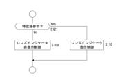
- FIG. 8 shows an example in which the determination condition is whether or not a specific operation has been performed by the user.
- the control unit 30 determines whether or not a specific operation is being performed. If a specific operation is being performed, the control unit 30 proceeds to step S110 and controls the display of the lens indicator 10. On the other hand, if the specific operation is not being performed, the control unit 30 performs processing for making the lens indicator 10 non-displayable in step S109.
- the specific operation may be, for example, a half-press of the shutter button 3.
- Half-pressing the shutter button 3 is an operation by the user to decide on a subject and execute autofocus. This is also the timing for the user to adjust the composition. Therefore, by displaying the lens indicator 10 when the button is half-pressed, it becomes easier for the user to adjust the composition.
- the specific operation may also be an operation other than half-pressing the shutter button 3 that triggers autofocus.
- the touch operation on the subject is regarded as a specific operation, and the lens indicator 10 is displayed.
- step S110 the process may proceed to step S108 shown in FIG. 6 or FIG. 7, and the display control of the lens indicator 10 may be performed for a predetermined period of time.
- the specific operation may be a dedicated button operation, etc.
- an indicator display button 24 is displayed on the display 2. While the user is pressing the indicator display button 24, the control unit 30 controls the display of the lens indicator 10 in step S110. In response to a single tap of the indicator display button 24, the control unit 30 may proceed to step S108 in FIG. 6 and perform display control for a predetermined period of time.
- Another possible display example is that, in a non-display state of the lens indicator 10, an indicator display button 24 is displayed at the position of the lens indicator 10, and when the user taps the indicator display button 24, the indicator display button 24 changes to (or is replaced by) the lens indicator 10.
- the lens indicator 10 is returned to the original indicator display button 24 upon a predetermined operation or the passage of a predetermined time.
- a predetermined operation a x button (close button) is displayed on the lens indicator 10, and the lens indicator 10 is returned to the indicator display button 24 by operating the x button.
- the predetermined operation may be a swipe operation of the lens indicator 10 to the edge of the screen.
- a specific operation by the user is used as a trigger for displaying the lens indicator 10, and this allows the display to be performed when necessary according to the user's will.
- the lens unit 5 is provided in the center of the short side direction of the second surface 200.
- the lens indicator 10 is displayed in a conspicuous position in the monitor area 20 on the display 2 of the first surface 100, which is highly likely to interfere with checking the subject.
- FIG. 11 shows an example in which the posture and movement state of the imaging device 1 (smartphone) itself are used as the judgment conditions.
- step S130 the control unit 30 determines the attitude and movement of the imaging device 1. For example, the control unit 30 obtains IMU data from the sensor unit 34 to detect the attitude and movement. It is also possible to predict the movement of the imaging device 1 from changes in the time axis direction of the captured image (monitor image).
- step S131 the control unit 30 determines whether or not a specific posture has been taken or a specific movement has been made.
- the specific posture and movement are, for example, the posture and movement of the imaging device 1 when the user assumes a posture to capture an image with the imaging device 1 .
- FIG. 12A shows an example of a state where the camera is not in a photographing posture
- FIG. 12B shows an example of a state where the camera is in a photographing posture.
- control unit 30 detects the posture of FIG. 12B or movement leading to this posture, it determines that a specific posture or movement has been detected, and proceeds from step S131 to step S108, and controls the display of the lens indicator 10 for a predetermined period of time. On the other hand, when it is determined that the posture or movement is not a specific one, the control unit 30 performs processing for making the lens indicator 10 non-displayable in step S109.
- the lens indicator 10 allows the lens indicator 10 to be displayed when the user is ready to take a photograph, that is, when the user is about to decide on the composition.
- the specific posture or movement may be determined to be a posture or movement other than a posture or movement that puts the user in a shooting position. For example, when the user gently shakes the imaging device 1 up and down, the lens indicator 10 may be displayed as the specific movement.
- the lens indicator 10 may be displayed only when camera shake or the like has subsided and the imaging device 1 is stationary.
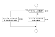
- FIG. 13 shows an example in which the use of a macro lens is set as a judgment condition.
- the control unit 30 determines whether or not a specific lens, which is a macro lens, among the plurality of lenses 6 has become available for use. If the macro lens is ready to be used, the control unit 30 proceeds to step S108 and controls the display of the lens indicator 10 for a predetermined period of time. On the other hand, if it is not time to use the macro lens, the control unit 30 performs processing to make the lens indicator 10 non-display in step S109.
- step S110 see FIG. 6
- the lens indicator 10 may continue to be displayed.
- FIG. 14 shows an example in which the distance from the image capture device 1 to the subject is used as a determination condition.
- the control unit 30 determines the distance to the subject from the distance measurement unit 35. For example, the control unit 30 obtains information as a depth map from the distance measurement unit 35, determines a main subject, and obtains distance information to the main subject from the position of the main subject and the depth map.
- step S151 the control unit 30 determines whether the obtained distance information is equal to or smaller than a predetermined distance as a preset threshold value. If the distance is equal to or shorter than the predetermined distance, the control unit 30 proceeds to step S108 and controls the display of the lens indicator 10 for a predetermined period of time. On the other hand, if the distance is not equal to or less than the predetermined distance, the control unit 30 performs processing for making the lens indicator 10 non-displayable in step S109.
- the lens indicator 10 allows the lens indicator 10 to be displayed when the subject is close, particularly when the parallax between the lenses 6 has a large effect on the composition.
- a method of measuring the distance by providing so-called image plane phase difference pixels in an image sensor.
- AI Artificial Intelligence
- any combination may be adopted, including the conditions in Fig. 6.
- the display/non-display of the lens indicator 10 can be controlled based on at least one of the conditions. Also, display/non-display control may be performed using a determination condition other than those exemplified. For example, it is possible to determine the type of subject and display the lens indicator 10 if the subject is a specific type.
- the display position of the lens indicator 10 is always directly behind the lens unit 5. For example, it is displayed in a position that covers the monitor area 20. For this reason, there is a possibility that the lens indicator 10 may get in the way of the display. Therefore, it is conceivable to display the lens indicator 10 with the transmittance as high as possible.
- Fig. 15A shows an example in which the lens indicator 10 is faintly displayed with the transmittance increased. For example, in the case of constant display, it is desirable to keep the transmittance increased in this way.
- Fig. 15B shows an example in which the lens indicator 10 is clearly displayed in a non-transparent state. This means that part of the display content is hidden by the lens indicator 10, but it is good for the user to check the lens position. For this reason, it is good to display it in this manner, for example, in cases where it is to be displayed only when the user wishes. For example, if you want the lens indicator 10 to be displayed only while the indicator display button 24 is pressed, it can be displayed non-transparently as in Fig. 15B.
- the transmittance may be varied depending on the display case. For example, when the display is to be performed in step S104 in the "ON" mode in the process of Fig. 6, the display is performed with the transmittance increased as shown in Fig. 15A. When the display is to be controlled for a predetermined time in step S108 in the "AUTO" mode, the transmittance may be decreased or the display may be performed in a non-transparent state as shown in Fig. 15B.
- the transmittance may also be changed depending on the subject position. For example, when the main subject determined by the main subject determination overlaps with the display position of the lens indicator 10, the transmittance of the lens indicator 10 is increased. This makes it possible to prevent the lens indicator 10 from interfering with the user's confirmation of the main subject.
- FIG. 16 shows an example in which the magnification of each lens 6 is displayed on the position mark 11 of the lens indicator 10.
- the control unit 30 when controlling the display of the lens indicator 10 in steps S104, S108, and S110 of FIG. 6, the control unit 30 also displays the zoom magnification of each lens 6.
- control unit 30 when the zoom magnification is changed by operating the zoom magnification button 22, the control unit 30 also changes the magnification value at the position mark 11.
- zoom magnification is displayed as "x1.0" here, the focal length may be displayed instead, or the user may be allowed to switch between the magnification display and the focal length display.
- the position mark 11 of the lens indicator 10 may be used as a zoom operator.
- Fig. 17 shows an example in which the position marks 11W and 11T can be slid sideways as indicated by the dashed lines.
- the user touches and slides the position mark 11T.
- This is a zoom operation of the telephoto lens 6T, and the zoom magnification is changed.
- the displayed magnification value is also updated.
- the slid position mark 11 may be displayed as an animation that returns to the original position when the operation is completed.
- each of the position marks 11U, 11W, and 11T may be used as a selection operator for the corresponding lens 6 (6U, 6W, and 6T).
- FIG. 18 shows an example of processing by the control unit 30.
- the control unit 30 monitors a touch operation on the position mark 11 of the lens indicator 10.
- control unit 30 proceeds to step S210 and performs lens switching control. For example, if the position mark 11U is touched, control is performed to set the ultra-wide lens 6U as the lens to be used.
- step S211 the control unit 30 performs processing to update the display of the lens indicator 10 in response to the lens switching. For example, the position mark 11 corresponding to the lens 6 that has become the newly used lens is highlighted.
- step S201 the control unit 30 monitors whether or not a slide operation has been performed on the position mark 11. If a slide operation is performed, the control unit 30 proceeds to step S220 and changes the zoom magnification in accordance with the amount of slide. That is, the control unit 30 instructs the lens unit 31 to drive the zoom lens. Alternatively, the control unit 30 may change the zoom magnification by electronic zoom processing performed by the imaging signal processing unit 30a.
- step S221 the control unit 30 performs processing to update the display of the lens indicator 10 in response to the change in zoom magnification. That is, it controls the movement of the position mark 11 in response to the slide operation and the change in the displayed magnification value.
- This type of processing also makes it possible to use the lens indicator 10 as a control for lens selection and zoom operation.
- the zoom magnification button 22 remains, but in cases where operation is possible using the lens indicator 10, the zoom magnification button 22 does not need to be displayed. For example, when the lens indicator 10 is not displayed, the zoom magnification button 22 may be displayed, and when the lens indicator 10 is displayed, the zoom magnification button 22 may be erased to widen the monitor area 20.
- the zoom magnification may be changed due to optical zoom by the lens system or due to electronic zoom by signal processing. It is preferable to be able to show the user whether the zoom magnification change is due to optical zoom or electronic zoom. Therefore, for example, during a slide operation, it is advisable to change the display mode, such as by changing the color of the position mark 11 during optical zoom and electronic zoom.
- This process can also be used in cases where the position mark 11 is not used as an operator.
- a slider 15 may be combined with the position mark 11 of the lens indicator 10.
- a pointer 16 indicates the current position (zoom magnification).
- the slider 15 indicates the zoom magnification range of the currently used lens with a solid line, and the zoom magnification range of other lenses with a dashed line.
- the telelens 6T corresponding to the position mark 11T is the currently used lens
- the zoom magnification range of the telelens 6T is indicated by a solid line.
- the zoom magnification can be changed by sliding the pointer 16 on a slider 15 .
- the zoom magnification can be changed by sliding the position mark 11T in FIG. 19A as in the example of FIG.
- the zoom magnification (and the lens used) is changed as shown in Fig. 19B.
- the zoom magnification range of the wide lens 6W corresponding to the position mark 11W is represented by a solid line.
- the slider 15 is shown with solid and dashed lines to distinguish the zoom magnification range of the lens being used, but this is not limited to solid and dashed lines, and the zoom magnification range of the currently used lens can be expressed in various display formats, such as using different colors.
- an operator that changes the zoom magnification by a sliding operation such as the slider 15 in FIG. 19, may be superimposed on or displayed near the lens indicator 10, but it does not have to be displayed all the time.
- the slider 15 or a gauge may be displayed, the zoom magnification may be presented, or a sliding operation may be possible.
- Fig. 20 shows an example of changing the display mode for lenses that are not compatible with the current state (lenses that cannot capture appropriate images). For example, in Fig. 20, position mark 11W is highlighted, indicating that wide lens 6W is currently the lens being used, while position mark 11T is grayed out (shown by a dashed line in the figure). This indicates that telephoto lens 6T is a lens that is not compatible with the current situation.
- control unit 30 performs the process shown in FIG. In step S250, the control unit 30 determines the distance to the subject, which is the same process as in step S150 in FIG.
- step S251 the control unit 30 determines whether or not there is a lens 6 that cannot be used with the current distance to the subject. For example, a lens that cannot focus because the distance is too close is determined to be an incompatible lens. If there is such a lens 6 that is incompatible with the current subject distance, the control unit 30 performs control to gray out the position mark 11 that corresponds to the lens 6 in question in step S252.
- step S260 the control unit 30 determines the current shooting mode.
- step S261 the control unit 30 determines whether or not there is a lens 6 that cannot support the current shooting mode. For example, in a configuration in which the optical system (and image sensor) of some lenses has a continuous shooting function, when the continuous shooting mode is selected, the lens 6 of the optical system that does not have the continuous shooting function is incompatible. Also, in a configuration in which the panoramic shooting function is possible only with some lenses 6, when the panoramic shooting mode is selected, the lens 6 of the optical system that does not have the panoramic shooting function is incompatible.
- control unit 30 performs control in step S262 to gray out the position mark 11 that corresponds to that lens 6.
- a touch operation on a grayed-out position mark 11 may be considered an invalid lens switching operation.
- an incompatible lens 6 is determined from the viewpoints of the distance from the subject and the shooting mode, but an incompatible lens 6 may be determined from other viewpoints and the display mode of the position mark 11 may be changed, such as by graying out.
- the background blurring function is a function that uses the parallax between the two lenses 6 to create a depth map, and performs blurring processing on the background area based on the depth map.
- Figure 22A shows an image captured by the ultra wide lens 6U
- Figure 22B shows an image captured by the wide lens 6W
- a depth map like that shown in Figure 22C is created by utilizing the parallax between these two captured images.
- the whiter the area in the map the closer the distance.
- range AR1 in Figure 22D is the range captured by the ultra wide lens 6U
- range AR2 is the range captured by the wide lens 6W
- a depth map can only be created for range AR2 captured by both lenses.
- the ultra-wide lens 6U is actually being used, from the user's perspective, only the range of the wide lens 6W can be captured. In this case, it may be possible to gray out the position mark 11U corresponding to the ultra-wide lens 6U.
- the imaging device 1 of the embodiment includes a display 2 provided on a first surface 100 of a housing, a lens 6 for imaging provided on a second surface 200 that is opposite to the first surface 100 of the housing, and a control unit 30 that performs control to display a lens indicator 10 indicating the lens 6 at a position on the display 2 where the lens 6 is projected from the second surface 200 onto the first surface 100. That is, the position of the lens 6 on the back surface of the display 2 is presented. This allows the user to recognize the position of the lens 6 on the back surface while viewing the subject image on the display 2 on the first surface 100. This makes it extremely easy to handle the smartphone (imaging device 1) so as to take an appropriate position relative to the subject.
- the control unit 30 causes the lens indicator 10 to display the positions of the plurality of lenses 6 and to execute a display that enables the lens being used to be identified.
- the position marks 11 of the lens indicator 10 of the display 2 allow the user to recognize the positions of the multiple lenses 6 on the back side of the surface being viewed.
- one of the position marks 11 is displayed in a high brightness or in a specific color, or the position marks 11 are highlighted in a different manner that is distinguishable from the other position marks 11, allowing the user to recognize the lens 6 currently being used for image capture.
- a smartphone since the user often does not know which lens 6 is being used, being able to recognize the lens being used makes it easier to take an appropriate position state with respect to the subject.
- the lens indicator 10 includes information on the zoom magnification of the lens 6 (see Figs. 16, 17, 20, etc.). This allows the user to recognize the zoom magnification of each lens. Additionally, the lens being used is clearly displayed, allowing you to see the current zoom ratio. Note that the focal length may be displayed instead of the zoom magnification, and the user may be allowed to select between the zoom magnification and the focal length.
- control unit 30 performs control to change the display of the zoom magnification on the lens indicator 10 in response to a change in the zoom magnification (see Figs. 16, 17, 18, etc.). This allows the user to recognize the zoom magnification of each lens and the zoom magnification of the lens 6 currently in use, and further allows the user to recognize the changed zoom magnification from the lens indicator 10 when the zoom magnification is changed by zooming operation.
- the control unit 30 performs switching control of the lens used for image capture in response to detection of a user operation on the lens indicator 10 (see FIG. 18). Since the position marks 11 of the lens indicator 10 correspond to the respective lenses 6, the user can intuitively perform an operation to specify a lens using the lens indicator 10. In other words, the lens indicator 10 (position marks 11) is also suitable for use as an operator for specifying a lens.
- the control unit 30 controls the display of the lens indicator 10 to display or not display depending on conditions (see Figs. 6 to 14).
- the lens indicator 10 is not always displayed, but is hidden or displayed according to conditions. Hiding the lens indicator 10 may make it easier to see the subject image in the monitor area 20, while displaying the lens indicator 10 may be more suitable for the user's shooting operation. Therefore, by turning on the lens indicator 10 at an appropriate timing when the lens indicator 10 is desired, comfortable operability can be provided to the user. Since the lens indicator 10 is always displayed at a position corresponding to the lens position, it may overlap with other icons displayed on the screen. Therefore, when the lens indicator 10 is displayed, control may be performed to change the display position of the overlapping icons to a position where they do not overlap.
- control unit 30 controls whether to display or hide the lens indicator 10 in accordance with the display mode of the lens indicator 10 selected by the user (see FIG. 6).
- the user can select "ON", “OFF”, or "AUTO” as the lens position display mode, and the display or non-display of the lens indicator 10 is controlled according to the selected mode. This makes it possible to realize the display of the lens indicator 10 according to the user's desire.
- control unit 30 performs control to display the lens indicator 10 in response to a specific operation by the user (see FIG. 8).
- a function of presenting the lens indicator 10 in conjunction with the user's operation can be realized.
- the display may end after a certain period of time, or the lens indicator 10 may continue to be displayed during the operation (or until an operation to cancel the display is performed).
- the half-press operation of the shutter button 3 is given (see FIG. 8).
- Half-pressing the shutter button 3 is an operation that triggers the start of autofocus.
- the control unit 30 displays the lens indicator 10, thereby informing the user of the lens position in a timely manner when the user is deciding on the composition of the subject.
- an operation that triggers the execution of autofocus is given (see FIG. 8).
- touching a specific subject in the monitor area 20 can be an operation to instruct the execution of autofocus on that subject.
- an autofocus button or the like can be displayed as a user interface and made operable.
- the control unit 30 can display the lens indicator 10 in response to an operation that triggers the start of the autofocus, thereby informing the user of the lens position in a timely manner when the user is deciding on the composition of the subject.
- the indicator display button 24 may be prepared and operated arbitrarily by the user.
- the control unit 30 may display the lens indicator 10 in response to the operation of the indicator display button 24, thereby making it possible to present the lens position at a timing desired by the user.
- the indicator display button 24 itself may be switched between display and non-display.
- the indicator display button 24 may be switched between display and non-display depending on the shooting mode, the display mode, the distance to the subject, the attitude or movement of the housing of the imaging device 1, the zoom operation, an operation to instruct execution of autofocus, etc. This allows the indicator display button 24 to be displayed when necessary, and the user to operate it as desired to display the lens indicator 10.
- an operation in which a zoom magnification is changed in response to the operation is given (see FIG. 7).
- the zoom magnification is changed by zooming to the telephoto side or the wide-angle side.
- the lens 6 may also be switched accordingly.
- the zoom magnification is also changed by the lens switching operation by the user. Therefore, the control unit 30 displays the lens indicator 10 in response to an operation that causes a change in the zoom magnification, such as a zoom operation or a lens switching operation, etc. This makes it possible to inform the user of the lens position when there is a lens switching or when the angle of view changes.
- control unit 30 performs control to display the lens indicator 10 in accordance with the determination result of the attitude or movement of the housing of the imaging device 1 (see Figs. 11 and 12).
- the control unit 30 estimates from detection information on the attitude and movement of the housing of the imaging device 1 itself that the user has taken a stance as if aiming at a subject, it displays the lens indicator 10. This allows the lens indicator 10 to be displayed at a timing when the user wants to recognize the lens position.
- control unit 30 performs control to display the lens indicator 10 when a specific lens 6 out of a plurality of lenses 6 is used (see steps S105 and S110 in FIG. 6).
- the control unit 30 displays the lens indicator 10 when the lens to be used in macro mode is selected. This allows the lens indicator 10 to be displayed at the required timing.
- control unit 30 performs control to display the lens indicator 10 in accordance with the measurement result of the distance to the subject (see FIG. 14).
- control unit 30 displays the lens indicator 10 when the distance to the main subject is equal to or shorter than a predetermined distance based on depth information to the main subject detected by the distance measuring unit 35. This makes it possible to display the lens indicator 10 at the required timing.
- control unit 30 controls the lens indicator 10 so that the display mode differs depending on whether the zoom operation is performed by optical zoom or electronic zoom (see FIG. 18).
- This allows the user to easily check whether the zoom operation is optical zoom or digital zoom, and also makes it easy to recognize when the zoom has switched from optical zoom to digital zoom.
- Such switching of the display mode can be applied to both an imaging device 1 equipped with a plurality of lenses and an imaging device 1 equipped with a single lens.
- control unit 30 controls the display mode of the lens indicator 10 to differ depending on the measurement result of the distance to the subject (see FIG. 21).
- the control unit 30 performs display control, such as graying out the position mark 11 of the incompatible lens. This allows the user to recognize the lens that cannot be selected.
- the display mode can be controlled to highlight or blink the position mark 11 of the recommended lens to prompt the user to perform a switching operation.
- the lens indicator 10 position mark 11 may be grayed out when the distance falls outside the range that can be handled.
- control unit 30 controls the indicator so that its display mode differs depending on the shooting mode (see FIG. 21).
- the control unit 30 performs display control such as graying out the position mark 11 of the incompatible lens. This allows the user to recognize the lens that cannot be selected in the current shooting mode.
- the display mode can be controlled so as to highlight or blink the position mark 11 of the recommended lens to prompt the user to perform a switching operation.
- the program of the embodiment is a program that causes the control unit 30 of the imaging device 1, which has a display 2 provided on the first surface 100 of the housing, and a lens 6 for capturing images provided on the second surface 200 of the housing that is the front and back surface of the first surface 100, to execute processing.
- the program causes an information processing device such as a CPU or DSP, or a device including these, to execute processing such as that shown in Figures 6, 7, 8, 11, 13, 14, 18, and 21.
- the program of the embodiment is a program that causes the control unit 30 of the imaging device 1 to execute control to display the lens indicator 10 indicating the lens 6 at the position on the display 2 where the lens 6 is projected from the second surface 200 onto the first surface 100.
- the functionality of this embodiment can be realized by including such a program in, for example, a smartphone camera application.
- Such a program can be recorded in advance in a HDD serving as a recording medium built into a device such as a computer device, or in a ROM within a microcomputer having a CPU.
- the software may be temporarily or permanently stored (recorded) on a removable recording medium such as a flexible disk, a CD-ROM (Compact Disc Read Only Memory), an MO (Magneto Optical) disk, a DVD (Digital Versatile Disc), a Blu-ray Disc (registered trademark), a magnetic disk, a semiconductor memory, a memory card, etc.
- a removable recording medium may be provided as a so-called package software.
- such a program can be installed in a personal computer or the like from a removable recording medium, or can be downloaded from a download site via a network such as a LAN (Local Area Network) or the Internet.
- LAN Local Area Network
- such a program is suitable for widespread provision of the imaging device 1 of the embodiment.
- a mobile terminal device such as a smartphone or tablet, an imaging device, a mobile phone, a personal computer, a game device, etc.
- the present technology can also be configured as follows. (1) A display provided on a first surface of the housing; a lens for capturing an image provided on a second surface of the housing, the second surface being in a front-back relationship with the first surface; a control unit that performs control to display an indicator indicating the lens at a position on the display where the lens is projected from the second surface to the first surface. (2) A plurality of the lenses are mounted on the first surface, The imaging device according to (1) above, wherein the control unit causes the indicator to display positions of the plurality of lenses and executes a display that enables identification of the lens being used for imaging. (3) The imaging device according to (1) or (2) above, wherein the indicator includes information on the zoom magnification of the lens.
- the indicator includes information about the zoom magnification of the lens;
- the imaging device according to any one of (1) to (3) above, wherein the control unit performs control to change the display of the zoom magnification on the indicator in response to a change in the zoom magnification.
- a plurality of the lenses are mounted on the first surface,
- the imaging device according to any one of (1) to (4), wherein the control unit performs switching control of a lens used for imaging in response to detecting a user operation on the indicator.
- the control unit controls display or non-display of the indicator depending on a condition.
- the imaging device controls whether to display or hide the indicator depending on a display mode of the indicator selected by a user.
- the control unit performs control to display the indicator in response to a specific operation by a user.
- the specific operation is a half-press of a shutter button.
- the specific operation is an operation that triggers the execution of autofocus.
- the specific operation is an operation of an operator for instructing display of an indicator.
- the imaging device according to any one of (8) to (11), wherein the specific operation is an operation in which a zoom magnification is changed in response to the operation.
- the control unit performs control to display the indicator depending on a determination result of an attitude or a movement of a housing of the imaging device.
- a plurality of the lenses are mounted on the first surface, The imaging device according to any one of (1) to (13) above, wherein the control unit performs control to display the indicator when a specific lens among the plurality of lenses is used.
- the control unit performs control to display the indicator depending on a measurement result of a distance to a subject.
- a display control method for an imaging device including a display provided on a first surface of a housing, and a lens for capturing an image provided on a second surface of the housing that is in a front-back relationship with the first surface, comprising: a display control method for displaying an indicator showing the lens at a position on the display where the lens is projected from the second surface to the first surface.
- a control unit of an imaging device including a display provided on a first surface of a housing, and a lens for capturing an image provided on a second surface of the housing that is in a front-back relationship with the first surface; a program that causes control to be executed to display an indicator showing the lens at a position on the display where the lens is projected from the second surface to the first surface.
Landscapes
- Engineering & Computer Science (AREA)
- Multimedia (AREA)
- Signal Processing (AREA)
- Human Computer Interaction (AREA)
- Theoretical Computer Science (AREA)
- General Engineering & Computer Science (AREA)
- Physics & Mathematics (AREA)
- General Physics & Mathematics (AREA)
- Computer Hardware Design (AREA)
- Indication In Cameras, And Counting Of Exposures (AREA)
- Studio Devices (AREA)
Priority Applications (3)
| Application Number | Priority Date | Filing Date | Title |
|---|---|---|---|
| JP2025516680A JPWO2024225009A1 (https=) | 2023-04-28 | 2024-04-08 | |
| EP24796765.6A EP4704435A1 (en) | 2023-04-28 | 2024-04-08 | Imaging device, display control method, and program |
| CN202480027024.8A CN121014210A (zh) | 2023-04-28 | 2024-04-08 | 成像装置、显示控制方法和程序 |
Applications Claiming Priority (2)
| Application Number | Priority Date | Filing Date | Title |
|---|---|---|---|
| JP2023074361 | 2023-04-28 | ||
| JP2023-074361 | 2023-04-28 |
Publications (1)
| Publication Number | Publication Date |
|---|---|
| WO2024225009A1 true WO2024225009A1 (ja) | 2024-10-31 |
Family
ID=93256324
Family Applications (1)
| Application Number | Title | Priority Date | Filing Date |
|---|---|---|---|
| PCT/JP2024/014284 Ceased WO2024225009A1 (ja) | 2023-04-28 | 2024-04-08 | 撮像装置、表示制御方法、プログラム |
Country Status (4)
| Country | Link |
|---|---|
| EP (1) | EP4704435A1 (https=) |
| JP (1) | JPWO2024225009A1 (https=) |
| CN (1) | CN121014210A (https=) |
| WO (1) | WO2024225009A1 (https=) |
Citations (7)
| Publication number | Priority date | Publication date | Assignee | Title |
|---|---|---|---|---|
| JP2007142793A (ja) * | 2005-11-18 | 2007-06-07 | Sony Corp | 撮影装置、表示制御方法、プログラム |
| JP2011205345A (ja) * | 2010-03-25 | 2011-10-13 | Nec Casio Mobile Communications Ltd | 撮像装置及びプログラム |
| WO2016174942A1 (ja) * | 2015-04-28 | 2016-11-03 | ソニー株式会社 | 情報処理装置、情報処理方法、およびプログラム |
| WO2020016966A1 (ja) | 2018-07-18 | 2020-01-23 | ソニー株式会社 | 情報処理装置、情報処理方法、およびプログラム |
| WO2020195292A1 (ja) * | 2019-03-26 | 2020-10-01 | ソニー株式会社 | 感覚器オブジェクトを表示する情報処理装置 |
| US20210191133A1 (en) * | 2019-12-23 | 2021-06-24 | Apple Inc. | External recording indicators |
| WO2022081283A1 (en) * | 2020-10-12 | 2022-04-21 | Qualcomm Incorporated | Under-display camera and sensor control |
-
2024
- 2024-04-08 WO PCT/JP2024/014284 patent/WO2024225009A1/ja not_active Ceased
- 2024-04-08 JP JP2025516680A patent/JPWO2024225009A1/ja active Pending
- 2024-04-08 CN CN202480027024.8A patent/CN121014210A/zh active Pending
- 2024-04-08 EP EP24796765.6A patent/EP4704435A1/en active Pending
Patent Citations (7)
| Publication number | Priority date | Publication date | Assignee | Title |
|---|---|---|---|---|
| JP2007142793A (ja) * | 2005-11-18 | 2007-06-07 | Sony Corp | 撮影装置、表示制御方法、プログラム |
| JP2011205345A (ja) * | 2010-03-25 | 2011-10-13 | Nec Casio Mobile Communications Ltd | 撮像装置及びプログラム |
| WO2016174942A1 (ja) * | 2015-04-28 | 2016-11-03 | ソニー株式会社 | 情報処理装置、情報処理方法、およびプログラム |
| WO2020016966A1 (ja) | 2018-07-18 | 2020-01-23 | ソニー株式会社 | 情報処理装置、情報処理方法、およびプログラム |
| WO2020195292A1 (ja) * | 2019-03-26 | 2020-10-01 | ソニー株式会社 | 感覚器オブジェクトを表示する情報処理装置 |
| US20210191133A1 (en) * | 2019-12-23 | 2021-06-24 | Apple Inc. | External recording indicators |
| WO2022081283A1 (en) * | 2020-10-12 | 2022-04-21 | Qualcomm Incorporated | Under-display camera and sensor control |
Also Published As
| Publication number | Publication date |
|---|---|
| CN121014210A (zh) | 2025-11-25 |
| EP4704435A1 (en) | 2026-03-04 |
| JPWO2024225009A1 (https=) | 2024-10-31 |
Similar Documents
| Publication | Publication Date | Title |
|---|---|---|
| JP6748582B2 (ja) | 撮像装置及びその制御方法、プログラム、並びに記録媒体 | |
| US9560261B2 (en) | Display control for a camera | |
| US8466996B2 (en) | Condition changing device | |
| US9363439B2 (en) | Photographing apparatus and operation control method for the same | |
| JP2010263425A (ja) | 撮像装置および撮像装置におけるモード切換え方法 | |
| CN108886565B (zh) | 相机 | |
| US10778892B2 (en) | Camera, setting method of camera, and setting program of camera | |
| CN110661946B (zh) | 电子设备、电子设备的控制方法和计算机可读介质 | |
| US12137288B2 (en) | Imaging device with blur indication | |
| JP5830564B2 (ja) | 撮像装置および撮像装置におけるモード切換え方法 | |
| JP2013009189A (ja) | 撮影装置および撮像方法 | |
| JP7423248B2 (ja) | 電子機器、電子機器の制御方法、プログラム及び記憶媒体 | |
| WO2021255975A1 (ja) | 撮像装置、撮像制御装置、撮像装置の制御方法、プログラム | |
| JP2019054378A (ja) | 撮像装置及びその制御方法、並びにプログラム | |
| WO2023058328A1 (ja) | 撮像装置、制御方法、プログラム | |
| US20250168510A1 (en) | Imaging device and zoom control method | |
| EP4704435A1 (en) | Imaging device, display control method, and program | |
| GB2598171A (en) | Display control apparatus and control method therefor and recording medium | |
| US11064128B2 (en) | Exposure setting apparatus, control method thereof, and storage medium | |
| JP7466304B2 (ja) | 撮像装置及びその制御方法、プログラム、記憶媒体 | |
| WO2024257425A1 (ja) | 撮像装置、撮像装置の制御方法、プログラム、および記憶媒体 | |
| JP2019053255A (ja) | 電子機器およびその制御方法 | |
| JP2025169795A (ja) | 撮像装置、その制御方法およびプログラム |
Legal Events
| Date | Code | Title | Description |
|---|---|---|---|
| 121 | Ep: the epo has been informed by wipo that ep was designated in this application |
Ref document number: 24796765 Country of ref document: EP Kind code of ref document: A1 |
|
| ENP | Entry into the national phase |
Ref document number: 2025516680 Country of ref document: JP Kind code of ref document: A |
|
| WWE | Wipo information: entry into national phase |
Ref document number: 2025516680 Country of ref document: JP |
|
| WWE | Wipo information: entry into national phase |
Ref document number: 2024796765 Country of ref document: EP |
|
| NENP | Non-entry into the national phase |
Ref country code: DE |
|
| ENP | Entry into the national phase |
Ref document number: 2024796765 Country of ref document: EP Effective date: 20251128 |
|
| ENP | Entry into the national phase |
Ref document number: 2024796765 Country of ref document: EP Effective date: 20251128 |
|
| ENP | Entry into the national phase |
Ref document number: 2024796765 Country of ref document: EP Effective date: 20251128 |
|
| ENP | Entry into the national phase |
Ref document number: 2024796765 Country of ref document: EP Effective date: 20251128 |
|
| ENP | Entry into the national phase |
Ref document number: 2024796765 Country of ref document: EP Effective date: 20251128 |
|
| ENP | Entry into the national phase |
Ref document number: 2024796765 Country of ref document: EP Effective date: 20251128 |
|
| ENP | Entry into the national phase |
Ref document number: 2024796765 Country of ref document: EP Effective date: 20251128 |
|
| ENP | Entry into the national phase |
Ref document number: 2024796765 Country of ref document: EP Effective date: 20251128 |
|
| ENP | Entry into the national phase |
Ref document number: 2024796765 Country of ref document: EP Effective date: 20251128 |
|
| WWP | Wipo information: published in national office |
Ref document number: 2024796765 Country of ref document: EP |