WO2024224949A1 - 電源装置、電源制御装置、及び電源制御プログラム - Google Patents
電源装置、電源制御装置、及び電源制御プログラム Download PDFInfo
- Publication number
- WO2024224949A1 WO2024224949A1 PCT/JP2024/013563 JP2024013563W WO2024224949A1 WO 2024224949 A1 WO2024224949 A1 WO 2024224949A1 JP 2024013563 W JP2024013563 W JP 2024013563W WO 2024224949 A1 WO2024224949 A1 WO 2024224949A1
- Authority
- WO
- WIPO (PCT)
- Prior art keywords
- power supply
- switch
- inverter
- storage battery
- control device
- Prior art date
- Legal status (The legal status is an assumption and is not a legal conclusion. Google has not performed a legal analysis and makes no representation as to the accuracy of the status listed.)
- Pending
Links
Images


Classifications
-
- B—PERFORMING OPERATIONS; TRANSPORTING
- B60—VEHICLES IN GENERAL
- B60L—PROPULSION OF ELECTRICALLY-PROPELLED VEHICLES; SUPPLYING ELECTRIC POWER FOR AUXILIARY EQUIPMENT OF ELECTRICALLY-PROPELLED VEHICLES; ELECTRODYNAMIC BRAKE SYSTEMS FOR VEHICLES IN GENERAL; MAGNETIC SUSPENSION OR LEVITATION FOR VEHICLES; MONITORING OPERATING VARIABLES OF ELECTRICALLY-PROPELLED VEHICLES; ELECTRIC SAFETY DEVICES FOR ELECTRICALLY-PROPELLED VEHICLES
- B60L1/00—Supplying electric power to auxiliary equipment of vehicles
-
- B—PERFORMING OPERATIONS; TRANSPORTING
- B60—VEHICLES IN GENERAL
- B60L—PROPULSION OF ELECTRICALLY-PROPELLED VEHICLES; SUPPLYING ELECTRIC POWER FOR AUXILIARY EQUIPMENT OF ELECTRICALLY-PROPELLED VEHICLES; ELECTRODYNAMIC BRAKE SYSTEMS FOR VEHICLES IN GENERAL; MAGNETIC SUSPENSION OR LEVITATION FOR VEHICLES; MONITORING OPERATING VARIABLES OF ELECTRICALLY-PROPELLED VEHICLES; ELECTRIC SAFETY DEVICES FOR ELECTRICALLY-PROPELLED VEHICLES
- B60L50/00—Electric propulsion with power supplied within the vehicle
- B60L50/50—Electric propulsion with power supplied within the vehicle using propulsion power supplied by batteries or fuel cells
- B60L50/60—Electric propulsion with power supplied within the vehicle using propulsion power supplied by batteries or fuel cells using power supplied by batteries
-
- B—PERFORMING OPERATIONS; TRANSPORTING
- B60—VEHICLES IN GENERAL
- B60L—PROPULSION OF ELECTRICALLY-PROPELLED VEHICLES; SUPPLYING ELECTRIC POWER FOR AUXILIARY EQUIPMENT OF ELECTRICALLY-PROPELLED VEHICLES; ELECTRODYNAMIC BRAKE SYSTEMS FOR VEHICLES IN GENERAL; MAGNETIC SUSPENSION OR LEVITATION FOR VEHICLES; MONITORING OPERATING VARIABLES OF ELECTRICALLY-PROPELLED VEHICLES; ELECTRIC SAFETY DEVICES FOR ELECTRICALLY-PROPELLED VEHICLES
- B60L53/00—Methods of charging batteries, specially adapted for electric vehicles; Charging stations or on-board charging equipment therefor; Exchange of energy storage elements in electric vehicles
- B60L53/10—Methods of charging batteries, specially adapted for electric vehicles; Charging stations or on-board charging equipment therefor; Exchange of energy storage elements in electric vehicles characterised by the energy transfer between the charging station and the vehicle
- B60L53/14—Conductive energy transfer
-
- B—PERFORMING OPERATIONS; TRANSPORTING
- B60—VEHICLES IN GENERAL
- B60L—PROPULSION OF ELECTRICALLY-PROPELLED VEHICLES; SUPPLYING ELECTRIC POWER FOR AUXILIARY EQUIPMENT OF ELECTRICALLY-PROPELLED VEHICLES; ELECTRODYNAMIC BRAKE SYSTEMS FOR VEHICLES IN GENERAL; MAGNETIC SUSPENSION OR LEVITATION FOR VEHICLES; MONITORING OPERATING VARIABLES OF ELECTRICALLY-PROPELLED VEHICLES; ELECTRIC SAFETY DEVICES FOR ELECTRICALLY-PROPELLED VEHICLES
- B60L53/00—Methods of charging batteries, specially adapted for electric vehicles; Charging stations or on-board charging equipment therefor; Exchange of energy storage elements in electric vehicles
- B60L53/20—Methods of charging batteries, specially adapted for electric vehicles; Charging stations or on-board charging equipment therefor; Exchange of energy storage elements in electric vehicles characterised by converters located in the vehicle
-
- H—ELECTRICITY
- H02—GENERATION; CONVERSION OR DISTRIBUTION OF ELECTRIC POWER
- H02J—CIRCUIT ARRANGEMENTS OR SYSTEMS FOR SUPPLYING OR DISTRIBUTING ELECTRIC POWER; SYSTEMS FOR STORING ELECTRIC ENERGY
- H02J1/00—Circuit arrangements for DC mains or DC distribution networks
-
- H—ELECTRICITY
- H02—GENERATION; CONVERSION OR DISTRIBUTION OF ELECTRIC POWER
- H02J—CIRCUIT ARRANGEMENTS OR SYSTEMS FOR SUPPLYING OR DISTRIBUTING ELECTRIC POWER; SYSTEMS FOR STORING ELECTRIC ENERGY
- H02J7/00—Circuit arrangements for charging or depolarising batteries or for supplying loads from batteries
Definitions
- This disclosure relates to a power supply device, a power supply control device, and a power supply control program.
- This disclosure has been made in consideration of the above circumstances, and its main purpose is to provide a power supply device, a power supply control device, and a power supply control program for miniaturizing the entire device.
- the first means for solving the above problem is a power supply device having a storage battery and connected to a motor via an inverter, the power supply device comprising: a first switch provided in a positive power supply path connected to the positive terminal of the storage battery; a second switch provided in a negative power supply path connected to the negative terminal of the storage battery; an insulated voltage conversion circuit in which an input section and an output section are electrically insulated; and a housing that accommodates the storage battery, the first switch, the second switch, and the voltage conversion circuit, in which the high-potential side electrical path of the input section is connected to a first end of both ends of the first switch, the high-potential side electrical path of the output section is connected to the remaining second end of both ends of the first switch, the low-potential side electrical path of the input section is connected to a first end of both ends of the second switch, and the low-potential side electrical path of the output section is connected to the remaining second end of both ends of the second switch.
- the first switch and the second switch for cutting off the current between the power supply path and the storage battery which are located outside the housing, are used when using the voltage conversion circuit and when cutting off the current between the storage battery and the inverter. This makes it possible to reduce the number of switches, simplifying and miniaturizing the device.
- the second means is a power supply control device for a power supply system including a storage battery, an inverter, and a motor connected to the storage battery via the inverter, the power supply system including a first switch provided in a positive power supply path between a positive terminal of the storage battery and a high potential terminal of the inverter, a second switch provided in a negative power supply path between a negative terminal of the storage battery and a low potential terminal of the inverter, and an insulated voltage conversion circuit in which an input section and an output section are electrically insulated, the high potential side electrical path of the input section being connected to a first end of the first switch, and the first switch is connected to a high potential side electrical path of the input section.
- the high-potential side electrical path of the output section is connected to the remaining second end of the switch
- the low-potential side electrical path of the input section is connected to the first end of the second switch
- the low-potential side electrical path of the output section is connected to the remaining second end of the second switch.
- a smoothing capacitor is provided between the positive power supply path and the negative power supply path, and the power supply control device inputs the power output from the storage battery to the smoothing capacitor via the voltage conversion circuit to charge it before switching the first switch and the second switch from off to on.
- the third means is a power supply device having a storage battery and connected to a motor via an inverter, and a power supply control program implemented by a power supply control device connected to the inverter and controlling the power supply device and the inverter, the power supply device having a first switch provided in a positive power supply path connected to a positive terminal of the storage battery, a second switch provided in a negative power supply path connected to a negative terminal of the storage battery, an insulated voltage conversion circuit in which an input section and an output section are electrically insulated, and a housing that houses the storage battery, the first switch, the second switch, and the voltage conversion circuit, the first end of the first switch is connected to a high-potential side electrical path of the input section, and the second switch is connected to a high-potential side electrical path of the input section.
- the high-potential side electrical path of the output section is connected to the remaining second end of the first switch
- the low-potential side electrical path of the input section is connected to the first end of the second switch
- the low-potential side electrical path of the output section is connected to the remaining second end of the second switch.
- the first switch and the second switch for cutting off the current between the power supply path and the storage battery which are located outside the housing, are used when using the voltage conversion circuit and when cutting off the current between the storage battery and the inverter. This makes it possible to reduce the number of switches, simplifying and miniaturizing the device.
- the fourth means is a power supply control program implemented by a power supply control device of a power supply system including a storage battery, an inverter, and a motor connected to the storage battery via the inverter, the power supply system including a first switch provided in a positive power supply path between a positive terminal of the storage battery and a high potential terminal of the inverter, a second switch provided in a negative power supply path between a negative terminal of the storage battery and a low potential terminal of the inverter, and an insulated voltage conversion circuit in which an input section and an output section are electrically insulated, and a first end of the first switch is connected to the high potential side electrical path of the input section.
- the high-potential side electrical path of the output section is connected to the remaining second end of the first switch
- the low-potential side electrical path of the input section is connected to the first end of the second switch
- the low-potential side electrical path of the output section is connected to the remaining second end of the second switch.
- a smoothing capacitor is provided between the positive power supply path and the negative power supply path, and the power supply control device inputs the power output from the storage battery to the smoothing capacitor via the voltage conversion circuit to charge it before switching the first switch and the second switch from off to on.
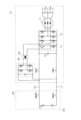
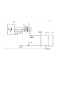
- FIG. 1 is a configuration diagram of a power supply system according to a first embodiment
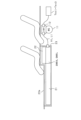
- FIG. 2 is a schematic diagram showing a housing of a battery pack
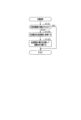
- FIG. 3 is a flowchart showing a procedure of a charging process.
- FIG. 4 is a configuration diagram of a power supply system of a comparative example.
- FIG. 5 is a configuration diagram of a power supply system of a comparative example.
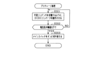
- FIG. 6 is a flowchart showing a procedure of a precharge process.
- FIG. 7 is a time chart showing changes in potential difference and current amount.
- FIG. 8 is a configuration diagram of a modified power supply system;
- FIG. 1 is a configuration diagram of a power supply system according to a first embodiment
- FIG. 2 is a schematic diagram showing a housing of a battery pack
- FIG. 3 is a flowchart showing a procedure of a charging process.
- FIG. 4 is a configuration diagram of a power supply system of a comparative example.
- FIG. 9 is a configuration diagram of a power supply system according to a modified example.
- FIG. 10 is a configuration diagram of a power supply system according to a modified example.
- FIG. 11 is a configuration diagram of a power supply system according to a modified example.
- FIG. 12 is a configuration diagram of a power supply system according to a modified example.
- FIG. 13 is a configuration diagram of a power supply system according to a modified example.
- FIG. 14 is a configuration diagram of a power supply system according to a modified example.
- the power supply system 100 includes a drive unit 10, a battery pack 20 as a power supply device, and a control device 50 as a power supply control device.
- the drive unit 10 is connected to the battery pack 20 via a positive power supply path H1 and a negative power supply path L1, and is supplied with power from the battery pack 20.
- the drive unit 10 is also configured to be connectable to an external charger 40, and power supplied from the external charger 40 can be supplied to the battery pack 20 via the drive unit 10.
- Each component will be described in detail below.
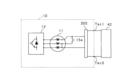
- the drive unit 10 includes a motor 11 and an inverter 12.
- the motor 11 is a three-phase synchronous machine, and includes star-connected armature windings 11a-11c of U, V, and W phases, and a rotor (not shown).
- the armature windings 11a-11c of each phase are arranged with an electrical angle of 120°.
- the motor 11 is, for example, a permanent magnet synchronous machine.
- the rotor is capable of transmitting power to the drive wheels of the vehicle. Therefore, the motor 11 serves as a source of torque that drives the vehicle.
- the inverter 12 is a three-phase full-bridge inverter having three phases of series connections (hereinafter referred to as legs) of upper arm switches SWH and lower arm switches SWL, which are connected in parallel.
- An upper arm diode DH which is a freewheel diode, is connected in inverse parallel (reverse polarity) to the upper arm switch SWH, and a lower arm diode DL, which is also a freewheel diode, is connected in inverse parallel to the lower arm switch SWL.
- each switch SWH, SWL is a semiconductor switch element, for example an IGBT, but may also be a MOSFET.
- the inverter 12 is equipped with a smoothing capacitor 13.
- the high-potential terminal of the smoothing capacitor 13 is connected to the positive power supply path H1.
- the low-potential terminal of the smoothing capacitor 13 is connected to the negative power supply path L1.
- the smoothing capacitor 13 may be provided outside the inverter 12.
- the first ends of the armature windings 11a to 11c are connected to the connection point between the emitter, which is the low potential terminal of the upper arm switch SWH, and the collector, which is the high potential terminal of the lower arm switch SWL, via a conductive member 14 such as a bus bar.
- the second ends of the armature windings 11a to 11c of each phase are configured to be connectable to each other at the neutral point. More specifically, the second end of the armature winding 11a is connected to the second end of the armature winding 11b via the relay switch 15a, and the second end of the armature winding 11b is connected to the second end of the armature winding 11c via the relay switch 15b. Therefore, by turning the relay switches 15a and 15b on and off, it is possible to switch between energization and de-energization between the second ends of the armature windings 11a to 11c. By turning the relay switches 15a and 15b on, the second ends of the armature windings 11a to 11c are connected to each other at the neutral point.
- the second ends of the armature windings 11a to 11c of each phase are connected to AC terminals Tac1 to Tac3 of the power supply system 100, respectively.
- the AC terminals Tac1 to Tac3 can be connected to a three-phase AC power supply (three-phase charger 41) as an external charger 40.
- the AC terminals Tac1 and Tac3 can be connected to a single-phase AC power supply (single-phase charger 42) as an external charger 40.
- the collector of the upper arm switch SWH of each phase is connected to the positive power supply path H1.
- the emitter of the lower arm switch SWL of each phase is connected to the negative power supply path L1. This connects the inverter 12 to the battery pack 20 via the positive power supply path H1 and the negative power supply path L1.
- the battery pack 20 includes a storage battery 21, a DC-DC converter 22 as an insulated voltage conversion circuit, a positive main switch SMRH provided in the positive power supply path H1, a negative main switch SMRL provided in the negative power supply path L1, and a housing 23 that houses them.
- the storage battery 21 is a power supply source for driving the rotor of the motor 11 to rotate.
- the storage battery 21 is a battery pack configured as a series connection of battery cells, which are single batteries.
- the positive terminal of the storage battery 21 is connected to the positive power supply path H1, and the negative terminal is connected to the negative power supply path L1.
- the inter-terminal voltages (e.g., rated voltages) of the battery cells that make up the battery pack are set to be the same, for example.
- the battery cells are, for example, secondary batteries such as lithium-ion batteries.
- the positive main switch SMRH is a switch that switches between energizing and de-energizing the positive power supply path H1 that connects the storage battery 21 and the inverter 12.
- the negative main switch SMRL is a switch that switches between energizing and de-energizing the negative power supply path L1 that connects the storage battery 21 and the inverter 12.
- the main switches SMRH and SMRL are mechanical relays. When the main switches SMRH and SMRL are turned off, they block the flow of current in both directions, and when they are turned on, they allow the flow of current in both directions.
- the main switch SMRH on the positive side and the main switch SMRL on the negative side are not limited to mechanical relays, and may be, for example, semiconductor switching elements.
- the DCDC converter 22 includes a primary circuit 31, a secondary circuit 32, and a transformer 33.
- One of the primary circuit 31 and the secondary circuit 32 is an input section, and the other is an output section. Note that the DCDC converter 22 switches between the input section and the output section as appropriate depending on its role.
- the transformer 33 includes a primary winding 34, a core 35, and a secondary winding 36 that is magnetically coupled to the primary winding 34 via the core 35.
- the primary winding 34 of the transformer 33 is connected to a primary circuit 31, and the secondary winding 36 of the transformer 33 is connected to a secondary circuit 32.
- the primary circuit 31 is a single-phase full-bridge circuit and includes two series connections (legs) of an upper arm switch SWH and a lower arm switch SWL, which are connected in parallel.
- An upper arm diode DH which is a freewheel diode, is connected in inverse parallel (reverse polarity) to the upper arm switch SWH, and a lower arm diode DL, which is also a freewheel diode, is connected in inverse parallel to the lower arm switch SWL.
- each switch SWH, SWL is a semiconductor switch element and may be an IGBT or a MOSFET.
- a first end of the primary winding 34 is connected to the first of the two legs that make up the primary circuit 31, and the remaining second end is connected to the second of the two legs that make up the primary circuit 31. More specifically, in each leg, an end of the primary winding 34 is connected to the connection point between the upper arm switch SWH and the lower arm switch SWL.
- the secondary circuit 32 is configured in the same way as the primary circuit 31, so a detailed description will be omitted.
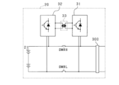
- the collectors (high potential terminals) of the upper arm switches SWH constituting the primary circuit 31 are connected to the positive power supply path H1 between the positive main switch SMRH and the inverter 12 via a high potential electrical path H11.
- the collectors (high potential terminals) of the upper arm switches SWH constituting the secondary circuit 32 are connected to the positive power supply path H1 between the positive main switch SMRH and the positive terminal of the storage battery 21 via a high potential electrical path H12.
- the high-potential side electrical path H11 of the primary circuit 31 is connected to the first end of the positive pole side main switch SMRH, and the high-potential side electrical path H12 of the secondary circuit 32 is connected to the remaining second end of the main switch SMRH.
- the emitters (low potential terminals) of the lower arm switches SWL constituting the primary circuit 31 are connected to the negative power supply path L1 between the negative main switch SMRL and the inverter 12 via a low potential electrical path L11.
- the emitters (low potential terminals) of the lower arm switches SWL constituting the secondary circuit 32 are connected to the negative power supply path L1 between the negative main switch SMRL and the negative terminal of the storage battery 21 via a low potential electrical path L12.
- the low-potential side electrical path L11 of the primary circuit 31 is connected to the first terminal of the negative main switch SMRL, and the low-potential side electrical path L12 of the secondary circuit 32 is connected to the remaining second terminal of the main switch SMRL.
- the housing 23 of the battery pack 20 will be described.
- the housing 23 is configured to be able to house the storage battery 21, the DCDC converter 22, the main switches SMRH and SMRL, at least a part of the positive power path H1, and at least a part of the negative power path L1. It is preferable that the housing 23 houses the contents in a manner that makes them inaccessible from the outside, but it does not matter if some of the contents are exposed.
- the material of the housing 23 may be a metal such as aluminum, or may be a resin.
- a part of the vehicle body (floor 23a in Fig. 2) may be used as a cover member that covers the opening of the housing 23.
- the control device 50 may be housed inside the battery pack 20, i.e., the housing 23, or may be located externally.
- the control device 50 of the power supply system 100 is mainly composed of a microcomputer, which has a CPU.
- the functions provided by the microcomputer can be provided by software recorded in a physical memory device and a computer that executes the software, software only, hardware only, or a combination of these.
- a microcontroller when a microcontroller is provided by an electronic circuit, which is hardware, it can be provided by a digital circuit including a large number of logic circuits, or an analog circuit.
- a microcontroller executes a program stored in a non-transitory tangible storage medium serving as a memory unit provided in the microcontroller.
- the program includes, for example, a program for the processing shown in FIG. 2, which will be described later.
- a program is executed, a method corresponding to the program is performed.
- the memory unit is, for example, a non-volatile memory.
- the program stored in the memory unit can be updated via a communication network such as the Internet, for example, over the air (OTA).
- OTA over the air
- the control device 50 performs switching control of the switches SWH, SWL that make up the inverter 12 to feedback control the control amount of the motor 11 to a command value based on the detection values of various sensors (not shown, such as a voltage sensor, a current sensor, and a rotation angle sensor).
- the control amount is, for example, torque.
- the upper arm switch SWH and the lower arm switch SWL are alternately turned on. This feedback control transmits the rotational power of the rotor to the drive wheels, causing the vehicle to run.
- the control device 50 performs charging processing related to charging control based on the battery state of the storage battery 21.
- the charging processing is executed at predetermined intervals while the vehicle is stopped and the storage battery 21's charge state (SOC: State Of Charge) is below a threshold value.
- SOC State Of Charge
- the control device 50 determines whether or not the external charger 40 is connected (step S101). If the result of this determination is negative, the charging processing is terminated.
- step S101 determines whether the power factor closer to 1.0 or reduce high-frequency components.
- the control device 50 controls the switches SWH, SWL of the inverter 12 to convert the power from the external charger 40 (step S102). Specifically, the control device 50 converts AC current to DC current. In doing so, the control device 50 uses the armature windings 11a-11c of the motor 11, the legs that constitute the inverter 12, and the smoothing capacitor 13 as a power factor correction circuit (PFC circuit) to convert the AC current to DC current so as to bring the power factor closer to 1.0 or reduce high-frequency components.
- PFC circuit power factor correction circuit
- control device 50 controls the DCDC converter 22 so that the converted power is input to the storage battery 21 for charging (step S103). More specifically, the control device 50 appropriately converts the voltage of the direct current input from the drive unit 10 via the power supply paths H1 and L1 using the DCDC converter 22, and inputs it to the storage battery 21 for charging.
- the first end of the positive main switch SMRH is connected to the high-potential side electrical path H11 of the primary circuit 31, and the second end is connected to the high-potential side electrical path H12 of the secondary circuit 32.
- the first end of the negative main switch SMRL is connected to the low-potential side electrical path L11 of the primary circuit 31, and the second end is connected to the low-potential side electrical path L12 of the secondary circuit 32.
- the voltage of the direct current converted by the inverter 12 can be converted by the DCDC converter 22 to charge the storage battery 21 while the main switches SMRH and SMRL are kept off, i.e., while remaining insulated. Therefore, the main switches SMRH and SMRL, which are arranged outside the housing 23 and are used to cut off the flow of electricity between the power supply paths H1 and L1 and the storage battery 21, can be used to cut off the flow of electricity between the storage battery 21 and the inverter 12 when the DCDC converter 22 is used.
- the comparative example shown in FIG. 4 is an example in which a DC-DC converter is housed in the drive unit 10, and part of the inverter 12 is used as the primary circuit. More specifically, a leg 71 is provided for the power supply paths H1, L1, and the primary circuit is formed by this leg 71 and any one of the multiple legs that make up the inverter 12. In this configuration, part of the electrical paths H12, L12 that connect the battery pack 20 and the secondary circuit 32 is disposed outside the battery pack 20 and drive unit 10. For this reason, for safety reasons, it becomes necessary to place relay switches SW1, SW2 on the electrical paths H12, L12 in the battery pack 20.
- the number of relay switches SW1 and SW2 can be reduced compared to the comparative example shown in FIG. 4.
- the comparative example shown in FIG. 5 is an example in which a DCDC converter is housed in the drive unit 10, similar to the comparative example shown in FIG. 4, and part of the inverter 12 is used as the primary circuit.
- the comparative example shown in FIG. 5 connects the electrical paths H12, L12 connected to the secondary circuit 32 to the power paths H1, L1 within the drive unit 10.
- the comparative example of FIG. 5 there is no need to provide a wire harness to connect the battery pack 20 and the drive unit 10, but in order to maintain insulation of the DCDC converter 22, it is necessary to provide new relay switches SW3, SW4 in the power paths H1, L1 within the drive unit 10.
- the DCDC converter 22 is housed in the battery pack 20. Therefore, in the power supply system 100, the main switches SMRH, SMRL for cutting off the current between the storage battery 21 and the power supply paths H1, L1 arranged outside the housing 23 can be used to cut off the current between the storage battery 21 and the inverter 12 when the DCDC converter 22 is used. Therefore, in the power supply system 100, the relay switches SW3, SW4 can be reduced compared to the comparative example shown in FIG. 5.
- the power supply system 100 can reduce the number of switches, wire harnesses, etc., simplifying the device and making it smaller.
- the inverter 12 is used in place of a PFC circuit and an AC/DC converter, so the circuit configuration can be simplified and made smaller.
- Second Embodiment A second embodiment will be described.
- the power output from the storage battery 21 is input to the smoothing capacitor 13 via the DCDC converter 22 to charge the smoothing capacitor 13. This suppresses the occurrence of an inrush current.
- the control device 50 performs the precharge process when it is determined that the main switches SMRH, SMRL should be switched from off to on.
- the timing for switching the main switches SMRH, SMRL from off to on is, for example, when the ignition switch is turned on, or when the start switch or power switch is turned on.
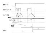
- the control device 50 When the precharge process is started, as shown in FIG. 6, the control device 50 operates the DCDC converter 22 while keeping the main switches SMRH and SMRL off to transfer power from the storage battery 21 to the smoothing capacitor 13 (step S201).
- step S201 as shown in FIG. 7, the control device 50 operates the DCDC converter 22 intermittently so that the smoothing capacitor 13 is gradually charged. At that time, the control device 50 gradually lengthens the operating time of the DCDC converter 22 so that the amount of current input to the smoothing capacitor 13 gradually increases, as shown in FIG. 7.
- the control device 50 After performing the process of step S201 for a predetermined time, the control device 50 acquires the potential difference between the first end and the second end of the main switch SMRH from a voltage sensor (not shown) or the like, and determines whether the potential difference is equal to or less than the threshold value (step S202). If the result of this determination is negative, the control device 50 performs the process of step S201 again. On the other hand, if the result of this determination is positive, the control device 50 switches the main switches SMRH and SMRL from off to on (step S203).
- the control device 50 Before switching the main switches SMRH and SMRL from off to on, the control device 50 inputs the power output from the storage battery 21 to the smoothing capacitor 13 via the DCDC converter 22 to charge it. This suppresses the occurrence of inrush current. Therefore, the inrush current can be suppressed without connecting a precharge circuit in parallel to the main switches SMRH and SMRL, and the circuit configuration can be simplified and made smaller.
- the control device 50 When charging the smoothing capacitor 13, the control device 50 operates the DCDC converter 22 intermittently as shown in FIG. 7 to gradually charge the smoothing capacitor 13. This ensures that inrush current is suppressed. Furthermore, when charging the smoothing capacitor 13, the control device 50 controls the DCDC converter 22 so that the operating time of the DCDC converter 22 gradually increases and the amount of current input to the smoothing capacitor 13 gradually increases. This makes it possible to shorten the charging time while suppressing the inrush current.
- a noise suppression circuit 300 such as a filter may be provided near the interface section of the battery pack 20.
- reactors 111a to 111c may be provided in place of the armature windings 11a to 11c, respectively, without using the motor 11.
- switches SW24 to SW25 for switching between energization and cut-off between the first ends of the armature windings 11b and 11c and the inverter 12.
- FIG. 10(b) may be used. In this way, by providing reactors 111a to 111c dedicated to charging, loss and noise can be reduced. Note that the noise reduction circuit 300 in FIG. 10 does not need to be provided.
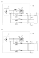
- FIG. 11 When only a single-phase charger 42 is used as the external charger 40, the circuit configuration shown in FIG. 11 may be used.
- a switch SW25 is provided between the armature winding 11c and the inverter 12, and a connection point P10 between the switch SW25 and the inverter 12 is connected to an AC terminal Tac3.
- a switch SW23 and a reactor 111c are provided in the electrical path between the connection point P10 and the AC terminal Tac3.
- An AC terminal Tac1 is connected to the neutral point of the armature windings 11a to 11c of the motor 11.
- a switch SW24 is provided in the electrical path between the neutral point and the AC terminal Tac1. Note that the noise reduction circuit 300 in FIG. 11 does not need to be provided.
- the drive unit 10 is equipped with a DCDC converter 22, and AC terminals Tac1 to Tac3 are connected to the primary circuit 31 of the DCDC converter 22 via a PFC circuit 212 and reactors 211a to 211c. Note that the noise reduction circuit 300 does not need to be provided in FIG. 12.
- AC terminals Tac1 to Tac3 are connected to the primary circuit 31 of the DCDC converter 22 housed in the battery pack 20 via the PFC circuit 212 and reactors 211a to 211c. Note that the noise reduction circuit 300 does not need to be provided in FIG. 13.
- the DCDC converter 22 is mounted on an on-board charger 500 separate from the battery pack 20 and the drive unit 10, and the AC terminals Tac1 to Tac3 are connected to the primary circuit 31 of the DCDC converter 22 via the PFC circuit 212 and reactors 211a to 211c. Note that the noise reduction circuit 300 in FIG. 13 does not need to be provided.
- control unit and the method described in the present disclosure may be realized by a dedicated computer provided by configuring a processor and memory programmed to execute one or more functions embodied in a computer program.
- control unit and the method described in the present disclosure may be realized by a dedicated computer provided by configuring a processor with one or more dedicated hardware logic circuits.
- control unit and the method described in the present disclosure may be realized by one or more dedicated computers configured by combining a processor and memory programmed to execute one or more functions with a processor configured with one or more hardware logic circuits.
- the computer program may be stored in a computer-readable non-transient tangible recording medium as instructions executed by the computer.
- a power supply control device for controlling the inverter, the first switch, the second switch, and the voltage conversion circuit
- the power supply control device when the first switch and the second switch are turned off and an external charger (40, 41, 42) is connected via the inverter, controls the inverter to convert AC current from the external charger into DC current, and controls the voltage conversion circuit to convert the voltage of the DC current converted by the inverter to charge the storage battery.
- a power supply control device for controlling the inverter, the first switch, the second switch, and the voltage conversion circuit
- a smoothing capacitor (13) is provided between the positive power supply path and the negative power supply path
- the power supply control device of configuration 1 or 2 wherein before switching the first switch and the second switch from off to on, the power output from the storage battery is input to the smoothing capacitor via the voltage conversion circuit to charge it.
- [Configuration 4] 4 4. The power supply device according to configuration 3, wherein the power supply control device controls the voltage conversion circuit so that an amount of current input to the smoothing capacitor gradually increases when the smoothing capacitor is charged.
- the power supply system includes: A first switch (SMRH) provided in a positive power supply path (H1) between a positive terminal of the storage battery and a high potential terminal of the inverter; a second switch (SMRL) provided in a negative power supply path (L1) between the negative terminal of the storage battery and the low potential terminal of the inverter; an insulation type voltage conversion circuit (22) in which an input section (31, 32) and an output section (31, 32) are electrically insulated from each other; a first end of the first switch is connected to a high potential side electrical path of the input unit, and a second end of the first switch is connected to a high potential side electrical path of the output unit, a first end of the second switch is connected to a low potential side electrical path of the input unit, and a second end of the second switch is connected to
- the power supply control device according to configuration 5, wherein, when the smoothing capacitor is charged, the power supply control device controls the voltage conversion circuit so that an amount of current input to the smoothing capacitor gradually increases.
- the power supply system includes a housing (23) that houses the storage battery, the first switch, the second switch, and the voltage conversion circuit, The power supply control device according to configuration 5 or 6, when the first switch and the second switch are turned off and an external charger (40, 41, 42) is connected via the inverter, controls the inverter to convert AC current from the external charger into DC current, and controls the voltage conversion circuit to convert the voltage of the DC current converted by the inverter to charge the storage battery.
- the power supply device is A first switch (SMRH) provided in a positive power supply path (H1) connected to a positive terminal of the storage battery;
- a second switch (SMRL) provided in a negative power supply path (L1) connected to a negative terminal of the storage battery;
- the power supply system includes: A first switch (SMRH) provided in a positive power supply path (H1) between a positive terminal of the storage battery and a high potential terminal of the inverter; a second switch (SMRL) provided in a negative power supply path (L1) between the negative terminal of the storage battery and the low potential terminal of the inverter; an insulation type voltage conversion circuit (22) in which an input section (31, 32) and an output section (31, 32) are electrically insulated from each other; a first end of the first switch is connected to a high potential side electrical path of the input unit, and a second end of the first switch is connected to a high potential side electrical path of the output unit, a first end of the second switch is connected to a low potential side electrical path of the input unit, and
Landscapes
- Engineering & Computer Science (AREA)
- Power Engineering (AREA)
- Transportation (AREA)
- Mechanical Engineering (AREA)
- Life Sciences & Earth Sciences (AREA)
- Sustainable Development (AREA)
- Sustainable Energy (AREA)
- Direct Current Feeding And Distribution (AREA)
- Electric Propulsion And Braking For Vehicles (AREA)
- Charge And Discharge Circuits For Batteries Or The Like (AREA)
Applications Claiming Priority (2)
| Application Number | Priority Date | Filing Date | Title |
|---|---|---|---|
| JP2023-071473 | 2023-04-25 | ||
| JP2023071473A JP2024157231A (ja) | 2023-04-25 | 2023-04-25 | 電源装置、電源制御装置、及び電源制御プログラム |
Publications (1)
| Publication Number | Publication Date |
|---|---|
| WO2024224949A1 true WO2024224949A1 (ja) | 2024-10-31 |
Family
ID=93256245
Family Applications (1)
| Application Number | Title | Priority Date | Filing Date |
|---|---|---|---|
| PCT/JP2024/013563 Pending WO2024224949A1 (ja) | 2023-04-25 | 2024-04-02 | 電源装置、電源制御装置、及び電源制御プログラム |
Country Status (2)
| Country | Link |
|---|---|
| JP (1) | JP2024157231A (enExample) |
| WO (1) | WO2024224949A1 (enExample) |
Citations (4)
| Publication number | Priority date | Publication date | Assignee | Title |
|---|---|---|---|---|
| JPH05336611A (ja) * | 1992-06-01 | 1993-12-17 | Fuji Electric Co Ltd | 電気自動車の電気システム |
| JP2017022805A (ja) * | 2015-07-07 | 2017-01-26 | トヨタ自動車株式会社 | 電気自動車 |
| JP2020058177A (ja) * | 2018-10-03 | 2020-04-09 | 日産自動車株式会社 | 充電制御方法および充電制御装置 |
| JP2020528254A (ja) * | 2018-02-14 | 2020-09-17 | エルジー・ケム・リミテッド | バッテリーと平滑キャパシタとの間のエネルギー伝達のための電源回路、バッテリー管理システム及びバッテリーパック |
-
2023
- 2023-04-25 JP JP2023071473A patent/JP2024157231A/ja active Pending
-
2024
- 2024-04-02 WO PCT/JP2024/013563 patent/WO2024224949A1/ja active Pending
Patent Citations (4)
| Publication number | Priority date | Publication date | Assignee | Title |
|---|---|---|---|---|
| JPH05336611A (ja) * | 1992-06-01 | 1993-12-17 | Fuji Electric Co Ltd | 電気自動車の電気システム |
| JP2017022805A (ja) * | 2015-07-07 | 2017-01-26 | トヨタ自動車株式会社 | 電気自動車 |
| JP2020528254A (ja) * | 2018-02-14 | 2020-09-17 | エルジー・ケム・リミテッド | バッテリーと平滑キャパシタとの間のエネルギー伝達のための電源回路、バッテリー管理システム及びバッテリーパック |
| JP2020058177A (ja) * | 2018-10-03 | 2020-04-09 | 日産自動車株式会社 | 充電制御方法および充電制御装置 |
Also Published As
| Publication number | Publication date |
|---|---|
| JP2024157231A (ja) | 2024-11-07 |
Similar Documents
| Publication | Publication Date | Title |
|---|---|---|
| CN103260931B (zh) | 电动车辆的电源装置及其控制方法 | |
| JP7241467B2 (ja) | 電気自動車またはハイブリッド自動車のための3相または単相充電システム | |
| JP6668930B2 (ja) | 電力変換装置および電動車両の制御装置 | |
| US20180361865A1 (en) | Power supply unit for a vehicle | |
| KR20210084758A (ko) | 차량용 배터리 시스템 및 그것의 동작 방법 | |
| JP7732234B2 (ja) | 電力変換装置 | |
| JP7790585B2 (ja) | 電力変換装置、プログラム及び制御方法 | |
| JP7244075B2 (ja) | 充電システム | |
| US20250167696A1 (en) | Power converter and non-transitory computer readable medium | |
| US20250038675A1 (en) | In-vehicle charging device | |
| WO2024224949A1 (ja) | 電源装置、電源制御装置、及び電源制御プログラム | |
| JP7718601B2 (ja) | 電力変換装置、プログラム | |
| JP2014239599A (ja) | 充電装置及び制御方法 | |
| WO2013046315A1 (ja) | 電動車両の電源システム | |
| KR102748614B1 (ko) | 차량용 인버터 시스템 및 그 제어 방법 | |
| KR102478188B1 (ko) | 차량용 인버터 시스템 및 그 제어 방법 | |
| KR102511726B1 (ko) | 멀티 충전 인버터 시스템 및 그 제어 방법 | |
| WO2024224950A1 (ja) | 電源システム及び電源制御プログラム | |
| US20240317090A1 (en) | Charging system for electric vehicle | |
| JP7708322B2 (ja) | 電力変換装置、プログラム | |
| CN119037114B (zh) | 具有集成充电功能的电动汽车三电机驱动系统及其工作方法 | |
| US20250074226A1 (en) | Electrified vehicle and method for controlling charging and discharging operations of the same | |
| WO2024214506A1 (ja) | 絶縁型電源装置、電源システム、及び電源制御プログラム | |
| WO2025177794A1 (ja) | 電力変換装置 | |
| WO2024209945A1 (ja) | 電源システム |
Legal Events
| Date | Code | Title | Description |
|---|---|---|---|
| 121 | Ep: the epo has been informed by wipo that ep was designated in this application |
Ref document number: 24796707 Country of ref document: EP Kind code of ref document: A1 |
|
| NENP | Non-entry into the national phase |
Ref country code: DE |