WO2024219433A1 - 光学ユニットおよび画像表示システム - Google Patents
光学ユニットおよび画像表示システム Download PDFInfo
- Publication number
- WO2024219433A1 WO2024219433A1 PCT/JP2024/015304 JP2024015304W WO2024219433A1 WO 2024219433 A1 WO2024219433 A1 WO 2024219433A1 JP 2024015304 W JP2024015304 W JP 2024015304W WO 2024219433 A1 WO2024219433 A1 WO 2024219433A1
- Authority
- WO
- WIPO (PCT)
- Prior art keywords
- liquid crystal
- light
- crystal layer
- optical unit
- layer
- Prior art date
- Legal status (The legal status is an assumption and is not a legal conclusion. Google has not performed a legal analysis and makes no representation as to the accuracy of the status listed.)
- Ceased
Links
Images






Classifications
-
- G—PHYSICS
- G02—OPTICS
- G02F—OPTICAL DEVICES OR ARRANGEMENTS FOR THE CONTROL OF LIGHT BY MODIFICATION OF THE OPTICAL PROPERTIES OF THE MEDIA OF THE ELEMENTS INVOLVED THEREIN; NON-LINEAR OPTICS; FREQUENCY-CHANGING OF LIGHT; OPTICAL LOGIC ELEMENTS; OPTICAL ANALOGUE/DIGITAL CONVERTERS
- G02F1/00—Devices or arrangements for the control of the intensity, colour, phase, polarisation or direction of light arriving from an independent light source, e.g. switching, gating or modulating; Non-linear optics
- G02F1/01—Devices or arrangements for the control of the intensity, colour, phase, polarisation or direction of light arriving from an independent light source, e.g. switching, gating or modulating; Non-linear optics for the control of the intensity, phase, polarisation or colour
- G02F1/13—Devices or arrangements for the control of the intensity, colour, phase, polarisation or direction of light arriving from an independent light source, e.g. switching, gating or modulating; Non-linear optics for the control of the intensity, phase, polarisation or colour based on liquid crystals, e.g. single liquid crystal display cells
- G02F1/133—Constructional arrangements; Operation of liquid crystal cells; Circuit arrangements
- G02F1/1333—Constructional arrangements; Manufacturing methods
- G02F1/1335—Structural association of cells with optical devices, e.g. polarisers or reflectors
- G02F1/133504—Diffusing, scattering, diffracting elements
-
- G—PHYSICS
- G02—OPTICS
- G02B—OPTICAL ELEMENTS, SYSTEMS OR APPARATUS
- G02B27/00—Optical systems or apparatus not provided for by any of the groups G02B1/00 - G02B26/00, G02B30/00
- G02B27/02—Viewing or reading apparatus
-
- G—PHYSICS
- G02—OPTICS
- G02B—OPTICAL ELEMENTS, SYSTEMS OR APPARATUS
- G02B5/00—Optical elements other than lenses
- G02B5/18—Diffraction gratings
-
- G—PHYSICS
- G02—OPTICS
- G02B—OPTICAL ELEMENTS, SYSTEMS OR APPARATUS
- G02B5/00—Optical elements other than lenses
- G02B5/30—Polarising elements
-
- G—PHYSICS
- G02—OPTICS
- G02B—OPTICAL ELEMENTS, SYSTEMS OR APPARATUS
- G02B5/00—Optical elements other than lenses
- G02B5/32—Holograms used as optical elements
-
- G—PHYSICS
- G02—OPTICS
- G02F—OPTICAL DEVICES OR ARRANGEMENTS FOR THE CONTROL OF LIGHT BY MODIFICATION OF THE OPTICAL PROPERTIES OF THE MEDIA OF THE ELEMENTS INVOLVED THEREIN; NON-LINEAR OPTICS; FREQUENCY-CHANGING OF LIGHT; OPTICAL LOGIC ELEMENTS; OPTICAL ANALOGUE/DIGITAL CONVERTERS
- G02F1/00—Devices or arrangements for the control of the intensity, colour, phase, polarisation or direction of light arriving from an independent light source, e.g. switching, gating or modulating; Non-linear optics
- G02F1/01—Devices or arrangements for the control of the intensity, colour, phase, polarisation or direction of light arriving from an independent light source, e.g. switching, gating or modulating; Non-linear optics for the control of the intensity, phase, polarisation or colour
- G02F1/13—Devices or arrangements for the control of the intensity, colour, phase, polarisation or direction of light arriving from an independent light source, e.g. switching, gating or modulating; Non-linear optics for the control of the intensity, phase, polarisation or colour based on liquid crystals, e.g. single liquid crystal display cells
-
- G—PHYSICS
- G02—OPTICS
- G02F—OPTICAL DEVICES OR ARRANGEMENTS FOR THE CONTROL OF LIGHT BY MODIFICATION OF THE OPTICAL PROPERTIES OF THE MEDIA OF THE ELEMENTS INVOLVED THEREIN; NON-LINEAR OPTICS; FREQUENCY-CHANGING OF LIGHT; OPTICAL LOGIC ELEMENTS; OPTICAL ANALOGUE/DIGITAL CONVERTERS
- G02F1/00—Devices or arrangements for the control of the intensity, colour, phase, polarisation or direction of light arriving from an independent light source, e.g. switching, gating or modulating; Non-linear optics
- G02F1/01—Devices or arrangements for the control of the intensity, colour, phase, polarisation or direction of light arriving from an independent light source, e.g. switching, gating or modulating; Non-linear optics for the control of the intensity, phase, polarisation or colour
- G02F1/13—Devices or arrangements for the control of the intensity, colour, phase, polarisation or direction of light arriving from an independent light source, e.g. switching, gating or modulating; Non-linear optics for the control of the intensity, phase, polarisation or colour based on liquid crystals, e.g. single liquid crystal display cells
- G02F1/133—Constructional arrangements; Operation of liquid crystal cells; Circuit arrangements
- G02F1/1333—Constructional arrangements; Manufacturing methods
- G02F1/1335—Structural association of cells with optical devices, e.g. polarisers or reflectors
-
- G—PHYSICS
- G02—OPTICS
- G02F—OPTICAL DEVICES OR ARRANGEMENTS FOR THE CONTROL OF LIGHT BY MODIFICATION OF THE OPTICAL PROPERTIES OF THE MEDIA OF THE ELEMENTS INVOLVED THEREIN; NON-LINEAR OPTICS; FREQUENCY-CHANGING OF LIGHT; OPTICAL LOGIC ELEMENTS; OPTICAL ANALOGUE/DIGITAL CONVERTERS
- G02F1/00—Devices or arrangements for the control of the intensity, colour, phase, polarisation or direction of light arriving from an independent light source, e.g. switching, gating or modulating; Non-linear optics
- G02F1/01—Devices or arrangements for the control of the intensity, colour, phase, polarisation or direction of light arriving from an independent light source, e.g. switching, gating or modulating; Non-linear optics for the control of the intensity, phase, polarisation or colour
- G02F1/13—Devices or arrangements for the control of the intensity, colour, phase, polarisation or direction of light arriving from an independent light source, e.g. switching, gating or modulating; Non-linear optics for the control of the intensity, phase, polarisation or colour based on liquid crystals, e.g. single liquid crystal display cells
- G02F1/133—Constructional arrangements; Operation of liquid crystal cells; Circuit arrangements
- G02F1/1333—Constructional arrangements; Manufacturing methods
- G02F1/1335—Structural association of cells with optical devices, e.g. polarisers or reflectors
- G02F1/133528—Polarisers
- G02F1/133541—Circular polarisers
-
- G—PHYSICS
- G02—OPTICS
- G02F—OPTICAL DEVICES OR ARRANGEMENTS FOR THE CONTROL OF LIGHT BY MODIFICATION OF THE OPTICAL PROPERTIES OF THE MEDIA OF THE ELEMENTS INVOLVED THEREIN; NON-LINEAR OPTICS; FREQUENCY-CHANGING OF LIGHT; OPTICAL LOGIC ELEMENTS; OPTICAL ANALOGUE/DIGITAL CONVERTERS
- G02F1/00—Devices or arrangements for the control of the intensity, colour, phase, polarisation or direction of light arriving from an independent light source, e.g. switching, gating or modulating; Non-linear optics
- G02F1/01—Devices or arrangements for the control of the intensity, colour, phase, polarisation or direction of light arriving from an independent light source, e.g. switching, gating or modulating; Non-linear optics for the control of the intensity, phase, polarisation or colour
- G02F1/13—Devices or arrangements for the control of the intensity, colour, phase, polarisation or direction of light arriving from an independent light source, e.g. switching, gating or modulating; Non-linear optics for the control of the intensity, phase, polarisation or colour based on liquid crystals, e.g. single liquid crystal display cells
- G02F1/133—Constructional arrangements; Operation of liquid crystal cells; Circuit arrangements
- G02F1/1333—Constructional arrangements; Manufacturing methods
- G02F1/1335—Structural association of cells with optical devices, e.g. polarisers or reflectors
- G02F1/133553—Reflecting elements
-
- G—PHYSICS
- G02—OPTICS
- G02F—OPTICAL DEVICES OR ARRANGEMENTS FOR THE CONTROL OF LIGHT BY MODIFICATION OF THE OPTICAL PROPERTIES OF THE MEDIA OF THE ELEMENTS INVOLVED THEREIN; NON-LINEAR OPTICS; FREQUENCY-CHANGING OF LIGHT; OPTICAL LOGIC ELEMENTS; OPTICAL ANALOGUE/DIGITAL CONVERTERS
- G02F1/00—Devices or arrangements for the control of the intensity, colour, phase, polarisation or direction of light arriving from an independent light source, e.g. switching, gating or modulating; Non-linear optics
- G02F1/01—Devices or arrangements for the control of the intensity, colour, phase, polarisation or direction of light arriving from an independent light source, e.g. switching, gating or modulating; Non-linear optics for the control of the intensity, phase, polarisation or colour
- G02F1/13—Devices or arrangements for the control of the intensity, colour, phase, polarisation or direction of light arriving from an independent light source, e.g. switching, gating or modulating; Non-linear optics for the control of the intensity, phase, polarisation or colour based on liquid crystals, e.g. single liquid crystal display cells
- G02F1/137—Devices or arrangements for the control of the intensity, colour, phase, polarisation or direction of light arriving from an independent light source, e.g. switching, gating or modulating; Non-linear optics for the control of the intensity, phase, polarisation or colour based on liquid crystals, e.g. single liquid crystal display cells characterised by the electro-optical or magneto-optical effect, e.g. field-induced phase transition, orientation effect, guest-host interaction or dynamic scattering
- G02F1/139—Devices or arrangements for the control of the intensity, colour, phase, polarisation or direction of light arriving from an independent light source, e.g. switching, gating or modulating; Non-linear optics for the control of the intensity, phase, polarisation or colour based on liquid crystals, e.g. single liquid crystal display cells characterised by the electro-optical or magneto-optical effect, e.g. field-induced phase transition, orientation effect, guest-host interaction or dynamic scattering based on orientation effects in which the liquid crystal remains transparent
- G02F1/1396—Devices or arrangements for the control of the intensity, colour, phase, polarisation or direction of light arriving from an independent light source, e.g. switching, gating or modulating; Non-linear optics for the control of the intensity, phase, polarisation or colour based on liquid crystals, e.g. single liquid crystal display cells characterised by the electro-optical or magneto-optical effect, e.g. field-induced phase transition, orientation effect, guest-host interaction or dynamic scattering based on orientation effects in which the liquid crystal remains transparent the liquid crystal being selectively controlled between a twisted state and a non-twisted state, e.g. TN-LC cell
- G02F1/1398—Devices or arrangements for the control of the intensity, colour, phase, polarisation or direction of light arriving from an independent light source, e.g. switching, gating or modulating; Non-linear optics for the control of the intensity, phase, polarisation or colour based on liquid crystals, e.g. single liquid crystal display cells characterised by the electro-optical or magneto-optical effect, e.g. field-induced phase transition, orientation effect, guest-host interaction or dynamic scattering based on orientation effects in which the liquid crystal remains transparent the liquid crystal being selectively controlled between a twisted state and a non-twisted state, e.g. TN-LC cell the twist being below 90°
-
- G—PHYSICS
- G03—PHOTOGRAPHY; CINEMATOGRAPHY; ANALOGOUS TECHNIQUES USING WAVES OTHER THAN OPTICAL WAVES; ELECTROGRAPHY; HOLOGRAPHY
- G03H—HOLOGRAPHIC PROCESSES OR APPARATUS
- G03H1/00—Holographic processes or apparatus using light, infrared or ultraviolet waves for obtaining holograms or for obtaining an image from them; Details peculiar thereto
- G03H1/0005—Adaptation of holography to specific applications
-
- G—PHYSICS
- G02—OPTICS
- G02F—OPTICAL DEVICES OR ARRANGEMENTS FOR THE CONTROL OF LIGHT BY MODIFICATION OF THE OPTICAL PROPERTIES OF THE MEDIA OF THE ELEMENTS INVOLVED THEREIN; NON-LINEAR OPTICS; FREQUENCY-CHANGING OF LIGHT; OPTICAL LOGIC ELEMENTS; OPTICAL ANALOGUE/DIGITAL CONVERTERS
- G02F2203/00—Function characteristic
- G02F2203/01—Function characteristic transmissive
-
- G—PHYSICS
- G03—PHOTOGRAPHY; CINEMATOGRAPHY; ANALOGOUS TECHNIQUES USING WAVES OTHER THAN OPTICAL WAVES; ELECTROGRAPHY; HOLOGRAPHY
- G03H—HOLOGRAPHIC PROCESSES OR APPARATUS
- G03H1/00—Holographic processes or apparatus using light, infrared or ultraviolet waves for obtaining holograms or for obtaining an image from them; Details peculiar thereto
- G03H1/0005—Adaptation of holography to specific applications
- G03H2001/0088—Adaptation of holography to specific applications for video-holography, i.e. integrating hologram acquisition, transmission and display
Definitions
- the present invention relates to an optical unit that constitutes a folded optical system, and an image display system that has this optical unit.
- a half mirror and a reflective polarizer are used to fold the optical path of the light (image) emitted by the image display device so that the user can observe it, thereby lengthening the optical path length and allowing the user to perceive the perspective of the image.
- a half mirror and a reflective polarizer are attached to a lens such as a convex lens, and light is collected by the lens, thereby widening the FOV (Field of View).
- Patent Document 1 discloses an image display system that uses a liquid crystal diffraction element (hologram) instead of a lens, an example of which is conceptually shown in FIG.
- hologram liquid crystal diffraction element
- an image display device 102 that is, a displayed image
- a circular polarizer 104 made up of a linear polarizer and a ⁇ /4 waveplate.
- This right-handed circularly polarized light then enters the half mirror 106 and is partially transmitted therethrough.
- the circularly polarized light transmitted through the half mirror 106 is then converted by the ⁇ /4 wave plate 108 into linearly polarized light, for example, in the up-down direction in the figure.
- This linearly polarized light then enters the reflective polarizer 110.
- the reflective polarizer 110 reflects linearly polarized light in the up-down direction in the figure. Therefore, the incident linearly polarized light in the up-down direction in the figure is reflected by the reflective polarizer 110. In other words, the optical path is folded back.
- the linearly polarized light in the vertical direction in the figure that is reflected, i.e., that has its optical path folded back, by the reflective polarizer 110 is incident again on the ⁇ /4 waveplate 108.
- the ⁇ /4 waveplate 108 converts right-handed circularly polarized light into linearly polarized light in the vertical direction in the figure. Therefore, the linearly polarized light in the vertical direction in the figure that is incident on the ⁇ /4 waveplate 108 is converted into right-handed circularly polarized light.
- This right-handed circularly polarized light is again incident on the half mirror 106 and is partially reflected.
- the right-handed circularly polarized light becomes left-handed circularly polarized light due to reflection by the half mirror 106, and is again incident on the ⁇ /4 wave plate 108.
- the ⁇ /4 wave plate 108 converts right-handed circularly polarized light into linearly polarized light in the up-down direction in the drawing. Therefore, left-handed circularly polarized light incident on the ⁇ /4 wave plate 108 is converted into linearly polarized light in the direction perpendicular to the paper surface.
- the linearly polarized light perpendicular to the paper surface converted by the ⁇ /4 wave plate 108 then enters the reflective polarizer 110.
- the reflective polarizer 110 reflects linearly polarized light in the up and down directions in the figure. Therefore, the linearly polarized light perpendicular to the paper surface that has entered the reflective polarizer 110 passes through the reflective polarizer 110 and enters the ⁇ /4 wave plate 114.
- the ⁇ /4 wave plate 114 converts linearly polarized light in the vertical direction in the figure into left-handed circularly polarized light. Therefore, the linearly polarized light in the vertical direction in the figure that is incident on the ⁇ /4 wave plate 114 becomes left-handed circularly polarized light and is incident on the liquid crystal diffraction element (hologram) 112.
- the liquid crystal diffraction element 112 has a liquid crystal orientation pattern in which the direction of the optical axis derived from the liquid crystal compound changes while rotating in one direction in the plane, in a radial or concentric manner (see FIG. 2). In this liquid crystal orientation pattern, when the length of the optical axis rotating 180° is taken as one period, this one period becomes gradually shorter from the center toward the outside.
- Such a liquid crystal diffraction element (liquid crystal diffraction lens) focuses right-handed or left-handed circularly polarized light and diverges the other.
- the liquid crystal diffraction element 112 in the illustrated example focuses left-handed circularly polarized light and diverges right-handed circularly polarized light.
- the left-handed circularly polarized light incident on the liquid crystal diffraction element 112 is focused by the liquid crystal diffraction element 112 and observed by the user U.
- a wide FOV is realized by the light collection using the liquid crystal diffraction element 112.
- the liquid crystal diffraction element 112 is a sheet-like member. Therefore, the image display system 100 that realizes a wide FOV by light collection using the liquid crystal diffraction element 112 can be made thinner than an image display system having a folding optical system using a conventional convex lens or the like.
- the bending angle of the liquid crystal diffraction element 112 increases from the center toward the periphery in the image display system 100.
- the diffraction efficiency of the liquid crystal diffraction element 112 is low near the ends.
- uneven brightness occurs in the observed image between the center and near the ends.
- the object of the present invention is to solve these problems with the conventional technology and to provide an optical unit that, when used in an image display system, produces an image with little uneven brightness, and an image display system that uses this optical unit.
- a light emitting device comprising, in order, a first partially reflective element, a second partially reflective element, and a polarizing diffractive element; the first partially reflective element and the second partially reflective element reflect a portion of the incident light and transmit a portion of the incident light;
- the polarizing diffraction element includes a liquid crystal layer formed using a liquid crystal composition containing a liquid crystal compound, the liquid crystal layer having a liquid crystal orientation pattern in which the direction of an optical axis derived from the liquid crystal compound changes while continuously rotating along at least one direction in a plane;
- the liquid crystal alignment pattern when the length of an optical axis direction originating from a liquid crystal compound rotates 180° in a plane as one period, there are regions in the plane where the length of one period is different, and further An optical unit having regions in its plane where an optical axis derived from a liquid crystal compound rotates twisted in the thickness direction of a liquid crystal layer, and having regions where the total magnitude of
- An optical element has a function of refracting incident light and has regions with different refractive indices at different positions in a plane.
- the optical unit according to any one of [1] to [7], comprising an optical element, a first partially reflective element, a second partially reflective element, and a polarizing diffraction element, in this order.
- An optical element comprising a liquid crystal layer formed using a liquid crystal composition containing a liquid crystal compound; the liquid crystal layer has a liquid crystal alignment pattern in which the direction of the optical axis derived from the liquid crystal compound changes while continuously rotating along at least one direction in the plane;
- the optical unit described in [8], wherein the liquid crystal orientation pattern has regions in the plane where the length of one period varies when the direction of the optical axis derived from the liquid crystal compound rotates 180° in the plane.
- An image display system comprising the optical unit according to any one of [1] to [9] and an image display device.
- the present invention provides an optical unit that, when used in an image display system, can reduce unevenness in the brightness of an observed image, and an image display system that uses this optical unit and reduces unevenness in the brightness of an observed image.
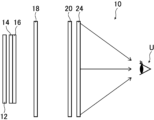
- FIG. 1 is a diagram conceptually showing an example of an image display system according to the present invention.
- FIG. 2 is a plan view conceptually illustrating an example of a polarizing diffraction element.
- FIG. 3 is a partial cross-sectional view conceptually showing the polarizing diffraction element shown in FIG.
- FIG. 4 is a partial cross-sectional view for explaining the polarizing diffraction element shown in FIG.
- FIG. 5 is a plan view for explaining the polarizing diffraction element shown in FIG.
- FIG. 6 is a conceptual diagram for explaining the function of the polarizing diffraction element shown in FIG.
- FIG. 7 is a conceptual diagram for explaining the function of the polarizing diffraction element shown in FIG.
- FIG. 1 is a diagram conceptually showing an example of an image display system according to the present invention.
- FIG. 2 is a plan view conceptually illustrating an example of a polarizing diffraction element.
- FIG. 3 is a partial cross
- FIG. 8 is a conceptual diagram for explaining the function of the polarizing diffraction element shown in FIG.
- FIG. 9 is a conceptual diagram for explaining another example of the liquid crystal layer.
- FIG. 10 is a conceptual diagram showing an exposure apparatus for forming a liquid crystal alignment pattern.
- FIG. 11 is a conceptual diagram for explaining another example of the liquid crystal layer.
- FIG. 12 is a conceptual diagram for explaining the liquid crystal layer shown in FIG.
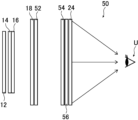
- FIG. 13 is a diagram conceptually showing another example of the image display system of the present invention.
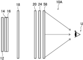
- FIG. 14 is a diagram conceptually showing another example of the image display system of the present invention.
- FIG. 15 is a diagram conceptually showing another example of the image display system of the present invention.
- FIG. 16 is a diagram conceptually showing another example of a conventional image display system.
- a numerical range expressed using "to” means a range that includes the numerical values before and after "to” as the lower and upper limits.
- light in the wavelength range of 420 to 490 nm is blue light (B light)
- light in the wavelength range of 495 to 570 nm is green light (G light)
- light in the wavelength range of 620 to 750 nm is red light (R light).
- FIG. 1 conceptually shows an example of an image display system of the present invention that uses an optical unit of the present invention.
- this image display system 10 is an image display system (VR system) for experiencing the above-mentioned virtual reality (VR).
- the half mirror 18 is the first partially reflecting element of the present invention.
- the circularly reflective polarizer 20 is the second partially reflecting element of the present invention.
- the polarizing diffraction element 24 is the polarizing diffraction element of the present invention. Therefore, in the illustrated image display system 10, the half mirror 18, the circularly reflective polarizer 20, and the polarizing diffraction element 24 constitute an optical unit of the present invention.
- the light emitted by the image display device 12 i.e., the displayed image
- a circular polarizer consisting of a linear polarizer 14 and a ⁇ /4 wavelength plate 16.
- the circular polarizer converts the light emitted by the image display device 12 into right-handed circularly polarized light.
- This right-handed circularly polarized light then enters the half mirror 18 and is partially transmitted therethrough.
- the right-handed circularly polarized light that has transmitted through the half mirror 18 then enters the circular reflective polarizer 20.
- the circular reflective polarizer 20 is a circular reflective polarizer that selectively reflects right-handed circularly polarized light and transmits left-handed circularly polarized light. Therefore, the right-handed circularly polarized light that has transmitted through the half mirror 18 is reflected by the circular reflective polarizer 20.
- the right-handed circularly polarized light reflected by the circularly reflective polarizer 20 then enters the half mirror 18 again, where a part of the light is reflected.
- the optical path of the light emitted from the image display device 12 is folded back. Due to this reflection by the half mirror 18, the right-handed circularly polarized light becomes left-handed circularly polarized light.
- the left circularly polarized light reflected by the half mirror 18 is again incident on the circular reflective polarizer 20.
- the circular reflective polarizer 20 is a circular reflective polarizer that selectively reflects right circularly polarized light and transmits left circularly polarized light. Therefore, the left circularly polarized light reflected by the half mirror 18 is transmitted through the circular reflective polarizer 20 and enters the polarizing diffraction element 24.
- the polarizing diffraction element 24 is a transmissive liquid crystal diffractive lens that selectively focuses right-handed or left-handed circularly polarized light.
- the polarizing diffraction element 24 is, as an example, a transmissive liquid crystal diffractive lens that selectively focuses left-handed circularly polarized light. Therefore, the left-handed circularly polarized light incident on the polarizing diffraction element 24 is condensed by the polarizing diffraction element 24 and observed by the user U.
- a wide FOV is achieved by focusing light using the polarizing diffraction element 24.
- the image display device 12 may be any of various known image display devices (displays).
- the image display device 12 include a liquid crystal display device (LCD (Liquid Crystal Display)), an organic electroluminescence display device (OLED (Organic Light Emitting Diode)), a CRT (cathode-ray tube), a plasma display device, an LED (Light Emitting Diode) display device, a micro LED display device, a DLP (Digital Light Processing), and a MEMS (Micro-Electro-Mechanical Systems) type display device.
- the liquid crystal display device includes an LCOS (Liquid Crystal On Silicon).
- the linear polarizer 14 and the ⁇ /4 wave plate 16 that constitute the circular polarizer are not limited, and various known ones can be used. Therefore, the polarizer may be a reflective polarizer or an absorptive polarizer, and various known linear polarizers can be used, such as an iodine-based polarizer, a dye-based polarizer using a dichroic dye, a polyene-based polarizer, a wire-grid polarizer, and a film obtained by stretching a dielectric multilayer film as described in JP2011-053705A, etc.
- various known ⁇ /4 wave plates can be used, such as a stretched polycarbonate film, a stretched norbornene-based polymer film, a transparent film containing and oriented with inorganic particles having birefringence such as strontium carbonate, a thin film formed by obliquely depositing an inorganic dielectric on a support, a film in which a polymerizable liquid crystal compound is uniaxially oriented and fixed in orientation, and a film in which a liquid crystal compound is uniaxially oriented and fixed in orientation.
- the image display device 12 emits linearly polarized light, such as a liquid crystal display device or an organic electroluminescence display device with an anti-reflection film, it is possible to use only the ⁇ /4 wave plate 16 without using the linear polarizer 14.
- the circular reflective polarizer 20 is not limited, and various known reflective circular polarizers that reflect right-handed or left-handed circularly polarized light and transmit circularly polarized light with the opposite rotation direction can be used.
- a preferred example of the circular reflective polarizer 20 is a cholesteric liquid crystal layer.
- the cholesteric liquid crystal layer is a liquid crystal layer in which a liquid crystal phase (cholesteric liquid crystal phase) made of a cholesterically oriented liquid crystal compound is fixed.
- a cholesteric liquid crystal layer has a helical structure in which liquid crystal compounds are spirally rotated and stacked, and a configuration in which the liquid crystal compounds are stacked in a spiral shape and rotated one turn (360° rotation) is defined as one helical pitch (helical pitch), and the helically rotating liquid crystal compounds are stacked at multiple pitches.
- a cholesteric liquid crystal layer selectively reflects right-handed or left-handed circularly polarized light in a specific wavelength range and transmits other light depending on the direction of rotation (sense) of the helix of the liquid crystal compound.
- the cholesteric liquid crystal layer selectively reflects light in a specific wavelength range and transmits light in other wavelength ranges according to the length of one helical pitch.
- One helical pitch P of the helical structure is the period of the helix, and is the length in the thickness direction that the liquid crystal compound rotates 360°.
- the cholesteric liquid crystal layer reflects right-handed circularly polarized light and transmits left-handed circularly polarized light, or reflects left-handed circularly polarized light and transmits right-handed circularly polarized light, depending on the sense of the helix.
- the sense of the helix of the cholesteric liquid crystal phase corresponds to the direction of rotation of the circularly polarized light reflected by the cholesteric liquid crystal layer.
- the cholesteric liquid crystal layer various known cholesteric liquid crystal layers having a fixed cholesteric liquid crystal phase can be used.
- the cholesteric liquid crystal layer may be a so-called pitch gradient cholesteric liquid crystal layer in which the helical pitch changes in the thickness direction.
- the cholesteric liquid crystal layer selectively reflects light in a specific wavelength range and transmits light in other wavelength ranges. Therefore, when the circular reflective polarizer 20 is constructed of a cholesteric liquid crystal layer, the circular reflective polarizer 20 may have only one cholesteric liquid crystal layer, or may have multiple cholesteric liquid crystal layers, depending on the image displayed by the image display device 12.
- the circular reflective polarizer 20 may have three cholesteric liquid crystal layers: a cholesteric liquid crystal layer having a selective reflection center wavelength in the wavelength range of blue light, a cholesteric liquid crystal layer having a selective reflection center wavelength in the wavelength range of green light, and a cholesteric liquid crystal layer having a selective reflection center wavelength in the wavelength range of red light.
- a volume hologram may be used as the first partially reflecting element instead of the half mirror 18.
- a volume hologram may be used as the second partially reflecting element instead of the circular reflecting polarizer 20 and a reflecting polarizer 54 (see FIG. 13) described later.
- a volume hologram also reflects part of the incident light and transmits part of it.
- various known types can be used, such as commercially available photopolymer films such as "BAYFOL HX120" and “BAYFOL HX200" (both trade names) available from Covestro, and "LithHolo C-RT20" (trade name) available from Liti Holographic.
- the polarizing diffraction element 24 is a transmissive liquid crystal diffractive lens that selectively focuses right-handed or left-handed circularly polarized light.
- the polarizing diffraction element 24 selectively focuses left-handed circularly polarized light, for example.
- the polarizing diffraction element 24 is the polarizing diffraction element (liquid crystal polarizing diffraction element) of the present invention, and is a characteristic member of the present invention.
- the polarizing diffraction element 24 has a liquid crystal layer 36 formed using a liquid crystal composition containing a liquid crystal compound 38 .
- the liquid crystal layer 36 has a liquid crystal orientation pattern in which the direction of the optical axis derived from the liquid crystal compound 38 changes while continuously rotating along at least one direction in the plane.
- the liquid crystal layer 36 when the length of the optical axis direction derived from the liquid crystal compound 38 rotating 180° in the plane is defined as one period, the liquid crystal layer 36 has regions in the plane where the length of one period is different. Furthermore, the liquid crystal layer 36 has regions within its plane where the optical axis originating from the liquid crystal compound 38 is twisted and rotated in the thickness direction of the liquid crystal layer 36, and has regions where the total magnitude of the twist angle in the thickness direction is different.
- the optical unit of the present invention comprises a half mirror 18 (first partially reflective element), a circularly reflective polarizer 20 (second partially reflective element), and a polarizing diffraction element 24, in that order, and the polarizing diffraction element 24 has the above-mentioned configuration, so that when used in an image display system such as a VR system, it is possible to display an image with little unevenness in the brightness of the observed image.
- the polarization diffraction element 24 has a substrate 32, an alignment film 34, and a liquid crystal layer 36.
- the liquid crystal layer 36 acts as a polarization diffraction element. Therefore, the polarizing diffraction element 24 may be composed of only the liquid crystal layer 36, or may be composed of the alignment film 34 and the liquid crystal layer 36 after the substrate 32 has been peeled off, or may be composed of the liquid crystal layer 36 laminated onto another substrate after the substrate 32 and alignment film 34 have been peeled off from the liquid crystal layer 36.
- the liquid crystal layer 36 is a liquid crystal layer formed on the alignment film 34 using a composition containing a liquid crystal compound 38, and the liquid crystal compound 38 is aligned and fixed in the liquid crystal alignment pattern described below.
- the liquid crystal layer 36 has a liquid crystal orientation pattern in which the direction of the optical axis derived from the liquid crystal compound 38 changes while continuously rotating in one direction, radially from the inside to the outside. That is, the liquid crystal orientation pattern of the liquid crystal layer 36 shown in Figures 2 and 3 is a concentric pattern in which the direction of the optical axis derived from the liquid crystal compound 38 changes while continuously rotating in one direction, concentrically from the inside to the outside.
- the liquid crystal layer 36 has a configuration in which the liquid crystal compound 38 is stacked in the thickness direction, similar to a liquid crystal layer formed using a composition containing a normal liquid crystal compound, as shown in Fig. 3.
- the liquid crystal layer 36 has a region in its plane where the liquid crystal compound 38 is twisted and rotated in the thickness direction, and has a region where the total magnitude of the twist angle in the thickness direction is different, as described above.
- a rod-shaped liquid crystal compound is exemplified as the liquid crystal compound 38 in FIGS. 2 and 3, the direction of the optical axis coincides with the longitudinal direction of the liquid crystal compound 38.
- the direction of the optical axis of the liquid crystal compound 38 changes while continuously rotating along a number of directions from the center, i.e., the optical axis, of the liquid crystal layer 36 toward the outside, for example, the direction indicated by the arrow A1 , the direction indicated by the arrow A2 , the direction indicated by the arrow A3 , the direction indicated by the arrow A4, .... Therefore, the rotation direction of the optical axis of the liquid crystal compound 38 is the same in all directions (one direction) in the liquid crystal layer 36.
- the rotation direction of the optical axis of the liquid crystal compound 38 is counterclockwise in all directions, including the direction indicated by the arrow A1 , the direction indicated by the arrow A2 , the direction indicated by the arrow A3, and the direction indicated by the arrow A4 . That is, if the arrows A1 and A4 are regarded as one straight line, the rotation direction of the optical axis of the liquid crystal compound 38 is reversed at the center of the liquid crystal layer 36 on this straight line. As an example, the straight line formed by the arrows A1 and A4 is directed to the right direction in the figure (the direction of the arrow A1 ).
- the optical axis of the liquid crystal compound 38 first rotates clockwise from the outside of the liquid crystal layer 36 to the center, the rotation direction is reversed at the center of the liquid crystal layer 36, and then rotates counterclockwise from the center of the liquid crystal layer 36 to the outside.
- the center of the liquid crystal layer 36 is the optical axis of the polarizing diffraction element.
- a liquid crystal layer having a liquid crystal orientation pattern in which the direction of the optical axis derived from liquid crystal compound 38 changes while continuously rotating in one direction acts as a transmissive liquid crystal diffraction element that diffracts the incident circularly polarized light in one direction and the opposite direction of the rotation of the optical axis depending on the rotation direction of the optical axis and the rotation direction of the incident circularly polarized light.
- the diffraction direction (refractive direction) of the transmitted light depends on the rotation direction of the optical axis of the liquid crystal compound 38. That is, in this liquid crystal orientation pattern, when the rotation direction of the optical axis of the liquid crystal compound 38 facing in one direction is reversed, the diffraction direction of the transmitted light becomes the opposite direction to the one direction in which the optical axis rotates.
- the diffraction direction of the transmitted light differs depending on the rotation direction of the incident circularly polarized light. That is, in this liquid crystal orientation pattern, the diffraction direction of the transmitted light is reversed when the incident light is right-handed circularly polarized light and when it is left-handed circularly polarized light.
- the length of one period of the liquid crystal orientation pattern is gradually shortened from the inside to the outside, when the length of the optical axis direction originating from the liquid crystal compound rotates 180° in one direction in which the direction of the optical axis of the liquid crystal compound 38 changes while rotating continuously.
- the shorter the length of one period the larger the diffraction angle. Therefore, in the liquid crystal layer 36 having a concentric liquid crystal orientation pattern, the diffraction angle gradually increases from the center of the concentric circles toward the outside.
- the liquid crystal layer 36 having a concentric liquid crystal orientation pattern in which the optical axis derived from the liquid crystal compound has a radially changing liquid crystal orientation pattern that continuously rotates can transmit incident light by diverging or converging it depending on the rotation direction of the optical axis of the liquid crystal compound 38 and the rotation direction of the incident circularly polarized light.
- the polarization diffraction element 24 having such a liquid crystal layer 36 acts, for example, as a concave lens when right-handed circularly polarized light is incident, and as a convex lens when left-handed circularly polarized light is incident, depending on the rotation direction of the incident circularly polarized light.
- the polarization diffraction element 24 acts as a convex lens when right-handed circularly polarized light is incident, and as a concave lens when left-handed circularly polarized light is incident.
- the liquid crystal layer 36 acts as a convex lens when left-handed circularly polarized light is incident, and focuses the left-handed circularly polarized light.
- the liquid crystal layer 36 is shown with only the liquid crystal compounds 38 (liquid crystal compound molecules) on the surface of the alignment film 34.
- the liquid crystal layer 36 has a structure in which aligned liquid crystal compounds 38 are stacked, similar to a liquid crystal layer formed using a composition containing a normal liquid crystal compound.
- this liquid crystal layer 36 will be described in detail below with reference to a liquid crystal layer 36A having a liquid crystal orientation pattern in which an optical axis 38A derived from a liquid crystal compound 38 changes while continuously rotating in one direction as indicated by arrow A, as conceptually shown in a plan view in Figure 5.
- the optical axis 38A originating from the liquid crystal compound 38 is also referred to as the "optical axis 38A of the liquid crystal compound 38" or the "optical axis 38A”.
- the liquid crystal compound 38 is two-dimensionally aligned in a plane parallel to one direction indicated by an arrow A and a Y direction perpendicular to the direction of the arrow A.
- the Y direction is perpendicular to the paper surface.
- the direction indicated by the arrow A will also be simply referred to as "the direction of the arrow A.”
- the circumferential direction of the concentric circles in the concentric liquid crystal alignment pattern corresponds to the Y direction in FIG.
- the liquid crystal layer 36A has a liquid crystal alignment pattern in which the direction of an optical axis 38A derived from the liquid crystal compound 38 changes while continuously rotating along the direction of the arrow A within the plane of the liquid crystal layer 36A.
- the direction of optical axis 38A of liquid crystal compound 38 changes while continuously rotating in the direction of arrow A (a predetermined direction), specifically means that the angle between optical axis 38A of liquid crystal compound 38 arranged along the direction of arrow A and the direction of arrow A differs depending on the position in the direction of arrow A, and the angle between optical axis 38A and the direction of arrow A changes sequentially from ⁇ to ⁇ +180° or ⁇ -180° along the direction of arrow A.
- the liquid crystal compounds 38 forming the liquid crystal layer 36A are arranged at equal intervals in the Y direction perpendicular to the direction of the arrow A, i.e., in the Y direction perpendicular to the direction in which the optical axis 38A continuously rotates, with the liquid crystal compounds 38 having the same orientation of the optical axis 38A being aligned.
- the angles between the optical axes 38A and the direction of the arrow A are equal between the liquid crystal compounds 38 aligned in the Y direction.
- regions in which the optical axis 38A is oriented in the same direction are formed in annular shapes that coincide with the center, forming a concentric liquid crystal orientation pattern.
- the length (distance) over which the optical axis 38A of the liquid crystal compound 38 rotates 180° is the length ⁇ of one period in the liquid crystal alignment pattern.
- one period ⁇ in the liquid crystal orientation pattern is defined as the length (distance) over which the optical axis 38A of the liquid crystal compound 38 rotates 180° in the direction of the arrow A, in which the orientation of the optical axis 38A continuously rotates and changes within the plane.
- one period ⁇ in the liquid crystal orientation pattern is defined as the distance over which the angle between the optical axis 38A of the liquid crystal compound 38 and the direction of the arrow A changes from ⁇ to ⁇ +180°.
- one period ⁇ is the distance between the centers of two liquid crystal compounds 38 that are at the same angle with respect to the direction of arrow A. Specifically, as shown in Fig. 5, one period ⁇ is the distance between the centers of two liquid crystal compounds 38 whose directions of arrow A and optical axes 38A coincide with each other.
- the liquid crystal orientation pattern repeats this one period ⁇ in the direction of arrow A, that is, in one direction in which the orientation of the optical axis 38A continuously rotates and changes.
- the liquid crystal layer 36A having such a liquid crystal orientation pattern is also a transmission type liquid crystal diffraction element, and this one period ⁇ is the period (one period) of the diffraction structure.
- the liquid crystal compounds aligned in the Y direction have the same angle between their optical axes 38A and the direction of the arrow A.
- a region R is defined as a region in which the liquid crystal compounds 38, whose optical axes 38A and the direction of the arrow A form the same angle, are arranged in the Y direction.
- the value of the in-plane retardation (Re) in each region R is preferably half the wavelength, i.e., ⁇ /2. This in-plane retardation is calculated by the product of the refractive index difference ⁇ n associated with the refractive index anisotropy of the region R and the thickness of the liquid crystal layer.
- the refractive index difference associated with the refractive index anisotropy of the region R in the liquid crystal layer is a refractive index difference defined by the difference between the refractive index in the direction of the slow axis in the plane of the region R and the refractive index in the direction perpendicular to the direction of the slow axis. That is, the refractive index difference ⁇ n associated with the refractive index anisotropy of the region R is equal to the difference between the refractive index of the liquid crystal compound 38 in the direction of the optical axis 38A and the refractive index of the liquid crystal compound 38 in the direction perpendicular to the optical axis 38A in the plane of the region R.
- the refractive index difference ⁇ n is equal to the refractive index difference of the liquid crystal compound.
- the region formed in a circular ring shape with the same center and in which the optical axis 38A has the same direction corresponds to region R in Figure 5.
- the incident light L1 which is left-handed circularly polarized
- the transmitted light L2 which is right-handed circularly polarized and inclined at a certain angle in the direction of the arrow A with respect to the incident direction.
- the transmitted light L5 travels in a direction different from that of the transmitted light L2 , that is, in the opposite direction to the direction of the arrow A with respect to the incident direction.
- the incident light L4 is converted into the transmitted light L5 of left-handed circular polarization tilted at a certain angle in the direction of the arrow A with respect to the incident direction.
- the in-plane retardation value of the multiple regions R is preferably a half wavelength
- the in-plane retardation Re(550) ⁇ n550 ⁇ d of the multiple regions R of the liquid crystal layer 36A satisfies formula (1), a sufficient amount of the circularly polarized component of the light incident on the liquid crystal layer 36A can be converted into circularly polarized light traveling in a direction tilted forward or backward with respect to the direction of arrow A.
- the in-plane retardation values of the multiple regions R in the liquid crystal layer 36A can be outside the range of the above formula (1).
- ⁇ n 550 ⁇ d ⁇ 200 nm or 350 nm ⁇ n 550 ⁇ d
- light can be separated into light traveling in the same direction as the incident light and light traveling in a direction different from the incident light.
- ⁇ n 550 ⁇ d approaches 0 nm or 550 nm
- the component of light traveling in the same direction as the incident light increases, and the component of light traveling in a direction different from the incident light decreases.
- the formula (2) indicates that the liquid crystal compound 38 contained in the liquid crystal layer 36A has reverse dispersion. That is, when the formula (2) is satisfied, the liquid crystal layer 36A can accommodate incident light with a wide band of wavelengths.
- the liquid crystal layer 36A can adjust the angles of diffraction of the transmitted light L2 and L5 by changing one period ⁇ of the formed liquid crystal orientation pattern. Specifically, the shorter one period ⁇ of the liquid crystal orientation pattern is, the stronger the interference between the lights that have passed through the adjacent liquid crystal compounds 38 becomes, so that the transmitted light L2 and L5 can be diffracted to a greater extent.
- the liquid crystal layer 36A by reversing the rotation direction of the optical axis 38A of the liquid crystal compound 38, which rotates along the direction of the arrow A, the direction of diffraction of the transmitted light can be reversed. Furthermore, the liquid crystal layer 36A diffracts transmitted light in opposite directions depending on the rotation direction of the incident circularly polarized light.
- the liquid crystal layer 36A diffracts transmitted light in opposite directions for right-handed circularly polarized light and left-handed circularly polarized light. As described above, the same can be said about the liquid crystal layer 36 having a concentric liquid crystal alignment pattern.
- the liquid crystal layer 36 has regions where the optical axis twists and rotates in the thickness direction of the liquid crystal layer 36, and has regions where the twist angle in the thickness direction is different. This point will be described in more detail later.
- the liquid crystal layer 36 is formed using a liquid crystal composition containing a rod-shaped liquid crystal compound or a discotic liquid crystal compound, and has a liquid crystal orientation pattern in which the optical axis of the rod-shaped liquid crystal compound or the optical axis of the discotic liquid crystal compound is oriented as described above.
- An alignment film 34 having an alignment pattern corresponding to the above-mentioned liquid crystal alignment pattern is formed on a substrate 32, and a liquid crystal composition is applied onto the alignment film 34 and cured, thereby forming a liquid crystal layer 36 consisting of a cured layer of the liquid crystal composition.
- the liquid crystal composition for forming the liquid crystal layer 36 contains a rod-shaped liquid crystal compound or a discotic liquid crystal compound, and may further contain other components such as a leveling agent, an alignment control agent, a polymerization initiator, and an alignment assistant.
- the liquid crystal layer 36 is preferably broadband with respect to the wavelength of the incident light, and is preferably constructed using a liquid crystal material with a birefringence that exhibits reverse dispersion. It is also preferable to make the liquid crystal layer 36 substantially broadband with respect to the wavelength of the incident light by imparting a twist component to the liquid crystal composition and by laminating different retardation layers. For example, a method of realizing a patterned ⁇ /2 plate with a broadband by laminating two layers of liquid crystal with different twist directions in the liquid crystal layer 36 is shown in JP 2014-089476 A and the like, and can be preferably used in the present invention.
- Rod-shaped liquid crystal compounds As the rod-shaped liquid crystal compound, azomethines, azoxys, cyanobiphenyls, cyanophenyl esters, benzoates, cyclohexane carboxylic acid phenyl esters, cyanophenylcyclohexanes, cyano-substituted phenylpyrimidines, alkoxy-substituted phenylpyrimidines, phenyldioxanes, tolanes, and alkenylcyclohexylbenzonitriles are preferably used. Not only the above-mentioned low molecular weight liquid crystal molecules, but also polymeric liquid crystal molecules can be used.
- the orientation of the rod-shaped liquid crystal compound it is more preferable to fix the orientation of the rod-shaped liquid crystal compound by polymerization, and an example of a polymerizable rod-shaped liquid crystal compound is Makromol. Chem. , Vol. 190, p. 2255 (1989), Advanced Materials, Vol. 5, p. 107 (1993), U.S. Patent Nos. 4,683,327, 5,622,648, and 5,770,107, International Publication Nos. 95/22586, 95/24455, 97/00600, 98/23580, and 98/52905, JP-A Nos. 1-272551, 6-16616, 7-110469, and 11-80081, and Japanese Patent Application No. 2001-64627 can be used.
- rod-shaped liquid crystal compounds those described in, for example, JP-T-11-513019 and JP-A-2007-279688 can also be preferably used.
- the discotic liquid crystal compound for example, those described in JP-A-2007-108732 and JP-A-2010-244038 can be preferably used.
- the liquid crystal compound 38 stands up in the thickness direction in the liquid crystal layer, and the optical axis 38A derived from the liquid crystal compound is defined as an axis perpendicular to the disc surface, that is, a so-called fast axis.
- the liquid crystal composition for forming the liquid crystal layer 36 may contain a photoreactive chiral agent.
- the photoreactive chiral agent is, for example, a compound represented by the following general formula (I), and has the property of being able to control the orientation structure of a liquid crystal compound and also being able to change the helical pitch of the liquid crystal compound, i.e., the twisting power (HTP: helical twisting power) of the helical structure by irradiation with light.
- the photoreactive chiral agent represented by the following general formula (I) can particularly greatly change the HTP of the liquid crystal molecule.
- R represents a hydrogen atom, an alkoxy group having 1 to 15 carbon atoms, an acryloyloxyalkyloxy group having a total of 3 to 15 carbon atoms, or a methacryloyloxyalkyloxy group having a total of 4 to 15 carbon atoms.
- the alkoxy group having 1 to 15 carbon atoms include a methoxy group, an ethoxy group, a propoxy group, a butoxy group, a hexyloxy group, and a dodecyloxy group.
- an alkoxy group having 1 to 12 carbon atoms is preferred, and an alkoxy group having 1 to 8 carbon atoms is particularly preferred.
- Examples of the acryloyloxyalkyloxy group having a total of 3 to 15 carbon atoms include an acryloyloxyethyloxy group, an acryloyloxybutyloxy group, and an acryloyloxydecyloxy group. Among these, an acryloyloxyalkyloxy group having 5 to 13 carbon atoms is preferred, and an acryloyloxyalkyloxy group having 5 to 11 carbon atoms is particularly preferred.
- Examples of the methacryloyloxyalkyloxy group having a total of 4 to 15 carbon atoms include a methacryloyloxyethyloxy group, a methacryloyloxybutyloxy group, and a methacryloyloxydecyloxy group.
- a methacryloyloxyalkyloxy group having 6 to 14 carbon atoms is preferred, and a methacryloyloxyalkyloxy group having 6 to 12 carbon atoms is particularly preferred.
- the molecular weight of the photoreactive chiral agent represented by the above general formula (I) is preferably 300 or more.
- the photoreactive chiral agent may be, for example, a photoreactive optically active compound represented by the following general formula (II):
- R represents a hydrogen atom, an alkoxy group having 1 to 15 carbon atoms, an acryloyloxyalkyloxy group having a total of 3 to 15 carbon atoms, or a methacryloyloxyalkyloxy group having a total of 4 to 15 carbon atoms.
- the alkoxy group having 1 to 15 carbon atoms include a methoxy group, an ethoxy group, a propoxy group, a butoxy group, a hexyloxy group, an octyloxy group, and a dodecyloxy group.
- an alkoxy group having 1 to 10 carbon atoms is preferable, and an alkoxy group having 1 to 8 carbon atoms is particularly preferable.
- Examples of the acryloyloxyalkyloxy group having a total of 3 to 15 carbon atoms include an acryloyloxy group, an acryloyloxyethyloxy group, an acryloyloxypropyloxy group, an acryloyloxyhexyloxy group, an acryloyloxybutyloxy group, and an acryloyloxydecyloxy group.
- an acryloyloxyalkyloxy group having 3 to 13 carbon atoms is preferred, and an acryloyloxyalkyloxy group having 3 to 11 carbon atoms is particularly preferred.
- Examples of the methacryloyloxyalkyloxy group having a total of 4 to 15 carbon atoms include a methacryloyloxy group, a methacryloyloxyethyloxy group, and a methacryloyloxyhexyloxy group.
- a methacryloyloxyalkyloxy group having 4 to 14 carbon atoms is preferred, and a methacryloyloxyalkyloxy group having 4 to 12 carbon atoms is particularly preferred.
- the molecular weight of the photoreactive optically active compound represented by the above general formula (II) is preferably 300 or more.
- the compound has high solubility with the liquid crystal compound described below, and it is more preferable that the solubility parameter SP value is close to that of the liquid crystal compound.
- photoreactive optically active compound represented by the above general formula (II) exemplary compounds (21) to (32) are shown below, but the present invention is not limited to these.
- the photoreactive chiral agent can also be used in combination with a non-photoreactive chiral agent, such as a chiral compound whose twisting power is highly temperature-dependent.
- a non-photoreactive chiral agent such as a chiral compound whose twisting power is highly temperature-dependent.
- non-photoreactive chiral agents include the chiral agents described in JP-A-2000-44451, JP-T-10-509726, WO98/00428, JP-T-2000-506873, JP-T-9-506088, Liquid Crystals (1996, 21, 327), Liquid Crystals (1998, 24, 219), etc.
- liquid crystal layer formed using a composition containing a liquid crystal compound and having a liquid crystal orientation pattern in which the direction of the optical axis 38A rotates along the direction of arrow A refracts circularly polarized light, and the smaller the period ⁇ of the liquid crystal orientation pattern, the larger the angle of refraction (diffraction). Therefore, for example, when a pattern is formed such that one period ⁇ of the liquid crystal orientation pattern is different in different regions in the plane, the brightness of the transmitted light changes depending on the angle of refraction when the light is incident on different regions in the plane and refracted at different angles. In particular, the transmitted light with a large angle of refraction becomes dark.
- the liquid crystal layer 36 constituting the polarizing diffraction element 24 has a liquid crystal orientation pattern in which the direction of the optical axis derived from the liquid crystal compound rotates in one direction, and further has a region in which the optical axis rotates twisted in the thickness direction of the liquid crystal layer, and has a region in which the total magnitude of the rotational twist angle in the thickness direction is different in the plane.
- the structure in which the optical axis of the liquid crystal compound rotates twisted in the thickness direction of the liquid crystal layer can be formed by adding the above-mentioned chiral agent to the liquid crystal composition.
- a configuration in which the twist angle in the thickness direction is different for each region in the plane can be formed by adding the above-mentioned photoreactive chiral agent to the liquid crystal composition and irradiating each region with a different amount of light.
- a polarizing diffraction element having such a liquid crystal layer has a small dependence of the amount of transmitted light within the plane on the refraction angle, and for example, when incident light is refracted at different angles in different regions within the plane, the transmitted light can be made brighter.
- the polarizing diffraction element 24 The function of the polarizing diffraction element 24 will now be described in detail with reference to the conceptual diagram of FIG.
- the polarization diffraction element 24 it is basically only the liquid crystal layer that exerts an optical effect. Therefore, in order to simplify the drawing and clearly show the configuration and the effects, in Fig. 8, the polarization diffraction element 24 is shown with only the liquid crystal layer 36.
- the liquid crystal layer 36 of the polarizing diffraction element 24 refracts the incident light in a predetermined direction and transmits it, targeting circularly polarized light. Note that in FIG. 8, the incident light is left-handed circularly polarized light.
- the liquid crystal layer 36 has three regions A0, A1, and A2 from the left side in Fig. 8, and the length ⁇ of one period is different in each region. Specifically, the length ⁇ of one period is shorter in the order of region A0, A1, and A2. Furthermore, regions A1 and A2 have a structure in which the optical axis is twisted and rotated in the thickness direction of the liquid crystal layer. In the following description, this structure in which the optical axis is twisted and rotated in the thickness direction of the liquid crystal layer is also referred to as a "twisted structure.”
- the twist angle in the thickness direction of the region A1 is smaller than the twist angle in the thickness direction of the region A2.
- the region A0 does not have a twist structure. That is, the twist angle in the thickness direction of the region A0 is 0°.
- the twist angle is the twist angle in the entire thickness direction.
- the polarizing diffraction element 24A when left-handed circularly polarized light LC1 is incident on the region A1 in the plane of the liquid crystal layer 36, as described above, it is refracted at a predetermined angle in the direction of arrow A with respect to the incident direction, i.e., in one direction in which the direction of the optical axis of the liquid crystal compound changes while continuously rotating, and is then transmitted.
- left-handed circularly polarized light LC2 is incident on the region A2 in the plane of the liquid crystal layer 36, it is refracted at a predetermined angle in the direction of arrow A with respect to the incident direction and is then transmitted.
- left-handed circularly polarized light LC0 when left-handed circularly polarized light LC0 is incident on the region A0 in the plane of the liquid crystal layer 36, it is refracted at a predetermined angle in the direction of arrow A with respect to the incident direction and is then transmitted.
- the angle of refraction by the liquid crystal layer 36 is shorter than the period ⁇ A1 of the liquid crystal orientation pattern in the region A1, the angle of refraction of the incident light, ⁇ A2 , of the transmitted light in the region A2 is larger than the angle ⁇ A1 of the transmitted light in the region A1, as shown in Fig. 8.
- the angle of refraction of the incident light, ⁇ A0 , of the transmitted light in the region A0 is smaller than the angle ⁇ A1 of the transmitted light in the region A1, as shown in Fig. 6 .
- the liquid crystal layer is configured to have regions with different lengths of one period in which the direction of the optical axis of the liquid crystal compound rotates 180° in the plane, the diffraction angle differs depending on the position of incidence of the light, and thus the amount of diffracted light differs depending on the position of incidence in the plane. In other words, regions in which the transmitted and diffracted light becomes dark are created depending on the position of incidence in the plane.
- the liquid crystal layer of the polarizing diffraction element has a region where it is twisted and rotated in the thickness direction, and has regions where the magnitude of the twist angle in the thickness direction varies.
- the twist angle ⁇ A2 in the thickness direction of the region A2 of the liquid crystal layer 36 is larger than the twist angle ⁇ A1 in the thickness direction of the region A1.
- the region A0 does not have a twist structure in the thickness direction. This makes it possible to suppress a decrease in the diffraction efficiency of the refracted light.
- the optical unit of the present invention can reduce the refraction angle dependency of the amount of transmitted light within the plane of the polarization diffraction element 24.
- the optical unit of the present invention can reduce luminance unevenness within the plane of the polarization diffraction element 24. Therefore, when the optical unit of the present invention is used in an image display system such as a VR system, it can display an image with less luminance unevenness in the observed image.
- the angle of light refraction within the plane of the liquid crystal layer 36 increases as one period ⁇ of the liquid crystal alignment pattern becomes shorter.
- the twist angle of the liquid crystal compound 38 in the thickness direction in the plane of the liquid crystal layer 36 is larger in a region with a short period ⁇ in which the direction of the optical axis 38A rotates 180° along the direction of the arrow A in the liquid crystal orientation pattern than in a region with a long period ⁇ .
- one period ⁇ A2 of the liquid crystal orientation pattern in the region A2 of the liquid crystal layer 36 is shorter than one period ⁇ A1 of the liquid crystal orientation pattern in the region A1, and the twist angle ⁇ A2 in the thickness direction is larger.
- the region A2 of the liquid crystal layer 36 on the light incident side refracts light more. Therefore, by setting the in-plane twist angle ⁇ in the thickness direction for one period ⁇ of the target liquid crystal orientation pattern, it is possible to suitably brighten the transmitted light that is refracted at different angles in different regions in the plane.
- the liquid crystal layer 36 has a larger thickness-direction twist angle (total of thickness-direction twist angles) of the liquid crystal compound 38 in a region having a shorter period in the liquid crystal alignment pattern.
- one period ⁇ of the liquid crystal orientation pattern becomes gradually shorter from the center toward the outside, so that it is preferable that the twist angle of the liquid crystal compound 38 in the thickness direction becomes gradually larger from the center toward the outside.
- the change in the period ⁇ and/or the change in the twist angle in the thickness direction of the liquid crystal compound 38 may be either stepwise or continuous.
- the present invention is not limited thereto, and there may be a region in which the permutation of the length of one period of the liquid crystal orientation pattern of the liquid crystal layer 36 coincides with the permutation of the magnitude of the twist angle in the thickness direction in the region where the length of one period is different.
- the twist angle in the thickness direction has a preferred range according to one period ⁇ of the in-plane liquid crystal orientation pattern, and may be set appropriately.
- the liquid crystal layer 36 of the polarizing diffraction element 24 preferably has a region in which the twist angle in the thickness direction is 10° to 360°.
- the twist angle in the thickness direction of the liquid crystal layer 36 of the polarizing diffraction element 24 may be appropriately set in accordance with one period ⁇ of the in-plane liquid crystal orientation pattern.
- one period ⁇ of the liquid crystal orientation pattern in the liquid crystal layer 36 may be set appropriately according to the angle of refraction (diffraction) required for the polarizing diffraction element 24.
- the liquid crystal layer 36 has a region in which the length of one period is 0.6 ⁇ m or less.
- a configuration in which the liquid crystal layer 36 has regions with different twist angles of the in-plane twist structure can be formed by using a liquid crystal composition containing a liquid crystal compound and a photoreactive chiral agent whose helical structure's twisting power (HTP) changes when irradiated with the above-mentioned light, and irradiating each region with light of a wavelength that changes the HTP of the chiral agent before or during curing of the liquid crystal composition that forms the liquid crystal layer 36, with different amounts of light being irradiated to each region.
- HTP helical structure's twisting power
- the HTP of the chiral agent decreases when irradiated with light.
- the amount of light irradiation for each region for example, in a region with a large amount of irradiation, the HTP decreases significantly and the induction of the helix decreases, so the twist angle of the twisted structure decreases.
- the decrease in HTP is small, so the twist angle of the twisted structure increases.
- a gradation mask is a mask whose transmittance to the irradiated light varies within its surface.
- the liquid crystal layer of the polarizing diffraction element may have regions that are twisted and rotated in the thickness direction (directions of twist angle) different from one another.
- a liquid crystal layer may have a liquid crystal orientation pattern in which the optical axis rotates in one direction, and further have a region in which the optical axis twists and rotates in the thickness direction of the liquid crystal layer, and have regions in which the twist angle of rotation is different within the plane, and the regions may have mutually different directions of twisting and rotating in the thickness direction. In this way, by having regions that are twisted and rotated in different directions in the thickness direction, transmitted light can be refracted efficiently for incident light of various polarization states in the regions having a twist angle in the thickness direction.
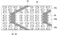
- a liquid crystal layer having the above-described liquid crystal orientation pattern has light and dark areas extending from one surface to the other surface in a cross-sectional image observed with a scanning electron microscope (SEM) at a cross section cut in the thickness direction along the direction in which the optical axis rotates continuously.
- the bright and dark portions have different tilt directions and angles depending on the presence or absence of twist in the liquid crystal compound 38 in the thickness direction, the twist direction and angle, and one period of the liquid crystal alignment pattern. For example, when the liquid crystal compound 38 is not twisted and rotated in the thickness direction, as in the above-mentioned region A0, it has light and dark portions extending in the thickness direction.
- the liquid crystal compound 38 when the liquid crystal compound 38 is twisted and rotated in the thickness direction as in the above-mentioned regions A1 and A2, the light and dark portions are inclined with respect to the thickness direction.
- the twist direction (rotation direction) of the liquid crystal compound when the twist direction (rotation direction) of the liquid crystal compound is reversed, the inclination directions of the light and dark portions are reversed.
- a region 36b in which the liquid crystal compound 38 is not twisted in the thickness direction is sandwiched between regions 36a and 36c in which the liquid crystal compound 38 is twisted in the thickness direction, so that a region having light portions 42 and dark portions 44 extending in the thickness direction is sandwiched between regions in which the light portions 42 and dark portions 44 are inclined in the opposite directions.
- the configuration in which the liquid crystal layer has a plurality of regions with different twist directions of the liquid crystal compound 38 is not limited to the region shown in FIG. 9, and various configurations can be used. That is, in the present invention, the liquid crystal layer can have various configurations, such as a configuration consisting of two regions, region 36a and region 36b, in which the twist directions of liquid crystal compound 38 in the thickness direction are opposite, a configuration consisting of four regions obtained by stacking two of these two regions, a configuration consisting of two regions, region 36a and region 36b, in which liquid crystal compound 38 is not twisted in the thickness direction, a configuration having a plurality of regions in which the inclination direction of the dark portions is the same but the inclination angles, i.e., the twist angles of the liquid crystal compound, are different, and a configuration in which region 36b in which liquid crystal compound 38 is not twisted is further stacked on top of the three regions shown in FIG. 9 .
- the twist angle of the liquid crystal compound 38 in the liquid crystal layer is the sum of the twist angles of the respective regions.
- the twist angle of liquid crystal compound 38 in region 36a is 80°
- the twist angle of liquid crystal compound 38 in central region 36b is 0°
- the twist angle of liquid crystal compound 38 in region 36c is -80°
- the twist angle of liquid crystal compound 38 in the liquid crystal layer will be "(80°) + (0°) + (-80°)", which is 0°.
- the absolute value of the total twist angle of the liquid crystal compound 38 increases toward the periphery.
- the polarizing diffraction element 24 includes the substrate 32, the alignment film 34, and the liquid crystal layer 36 described above.
- the substrate 32 constituting the polarizing diffraction element 24 may be made of various sheet-like materials as long as it can support the alignment film 34 and the liquid crystal layer 36 (described later).
- the substrate 32 is preferably a transparent support, and examples of the support include a polyacrylic resin film such as polymethyl methacrylate, a cellulose resin film such as cellulose triacetate, a cycloolefin polymer film (for example, trade name "Arton” manufactured by JSR Corporation, trade name "ZEONOR” manufactured by Zeon Corporation), polyethylene terephthalate (PET), polycarbonate, and polyvinyl chloride.
- an alignment film 34 is formed on the surface of such a substrate 32.
- the liquid crystal orientation pattern in the liquid crystal layer 36 follows the orientation pattern formed in the orientation film 34. Therefore, the same orientation pattern as the liquid crystal orientation pattern in the liquid crystal layer 36 is formed in the orientation film 34 for forming a liquid crystal layer having such a liquid crystal orientation pattern.
- Figure 10 conceptually shows an example of an exposure device that exposes a coating film that will become the alignment film 34 (photoalignment film) for forming the liquid crystal layer 36, to form an alignment pattern that corresponds to a concentric liquid crystal alignment pattern in which the optical axis changes radially by continuously rotating.
- a light source 84 equipped with a laser 82, a polarizing beam splitter 86 that splits laser light M from the laser 82 into S-polarized light MS and P-polarized light MP, a mirror 90A arranged in the optical path of the P-polarized light MP, a mirror 90B arranged in the optical path of the S-polarized light MS, a lens 92 arranged in the optical path of the S-polarized light MS, a beam splitter 94, and a ⁇ /4 plate 96.
- the P-polarized light MP split by the polarizing beam splitter 86 is reflected by a mirror 90A and enters a beam splitter 94.
- the S-polarized light MS split by the polarizing beam splitter 86 is reflected by a mirror 90B, collected by a lens 92, and enters the beam splitter 94.
- the P-polarized light MP and S-polarized light MS are combined by a beam splitter 94 , and are converted by a ⁇ /4 plate 96 into right-handed circularly polarized light and left-handed circularly polarized light according to the polarization direction, and are incident on the alignment film 34 on the substrate 32 .
- the polarization state of the light irradiated onto the alignment film 34 changes periodically in the form of interference fringes.
- an exposure pattern is obtained in which the pitch (one period) changes from the inside to the outside.
- a radial (concentric) alignment pattern in which the alignment state changes periodically is obtained in the alignment film 34.
- one period ⁇ of the liquid crystal orientation pattern in which the optical axis of the liquid crystal compound 38 continuously rotates 180° along one direction can be controlled by changing the refractive power of the lens 92, the focal length of the lens 92, and the distance between the lens 92 and the orientation film 34, etc.
- the refractive power of the lens 92 the F-number of the lens 92
- the length of one period of the liquid crystal alignment pattern can be changed in one direction in which the optical axis rotates continuously.
- the length of one period of the liquid crystal orientation pattern can be changed in one direction in which the optical axis rotates continuously, depending on the spread angle of the light spread by the lens 92 that interferes with the parallel light.
- the refractive power of the lens 92 when the refractive power of the lens 92 is weakened, the light approaches parallel light, and the length ⁇ of one period of the liquid crystal orientation pattern gradually shortens from the inside to the outside. Conversely, when the refractive power of the lens 92 is strengthened, the length ⁇ of one period of the liquid crystal orientation pattern suddenly shortens from the inside to the outside. That is, by adjusting the refractive index of the lens 92, it is possible to adjust the refractive index of the polarizing diffraction element 24 (liquid crystal layer 36) which acts as a concave lens or a convex lens depending on the rotation direction of the incident circularly polarized light.
- a liquid crystal composition containing a liquid crystal compound and a photoreactive chiral agent for forming the above-mentioned liquid crystal layer 36 is applied to the exposed alignment film 34 thus formed, dried, and exposed using the gradation mask as described above, and further cured by ultraviolet irradiation or the like as necessary.
- This allows the formation of a liquid crystal layer 36 having a concentric liquid crystal orientation pattern as described above, regions in the plane where the length of one period of the liquid crystal orientation pattern is different, regions in the plane where the liquid crystal compound twists and rotates in the thickness direction, and further regions where the total magnitude of the twist angle is different, thereby producing a polarizing diffraction element 24 as shown in Figures 2 and 3.
- Photoalignment materials used in photoalignment films are described, for example, in JP-A-2006-285197, JP-A-2007-76839, JP-A-2007-138138, JP-A-2007-94071, JP-A-2007-121721, JP-A-2007-140465, and JP-A-2007-156439.
- photocrosslinkable polyimides photocrosslinkable polyamides and photocrosslinkable esters described in JP-T-2003-520878, JP-T-2004-529220 and Japanese Patent No. 4162850
- photodimerizable compounds described in JP-A-9-118717, JP-T-10-506420, JP-T-2003-505561, WO 2010 / 150748, JP-A-2013-177561 and JP-A-2014-12823, in particular cinnamate compounds, chalcone compounds and coumarin compounds are exemplified as preferred examples.
- azo compounds photocrosslinkable polyimides, photocrosslinkable polyamides, photocrosslinkable esters, cinnamate compounds, and chalcone compounds are preferably used.
- the present invention is not limited to this. That is, in the optical unit of the present invention, the polarizing diffraction element may have a plurality of liquid crystal layers.
- a polarizing diffraction element having a plurality of liquid crystal layers and having wavelength-selective retardation layers provided between the liquid crystal layers is exemplified.
- the wavelength-selective retardation layer is a member that converts circularly polarized light in a specific wavelength range into circularly polarized light having the opposite rotation direction.
- the liquid crystal layer having the above-mentioned liquid crystal orientation pattern refracts and transmits circularly polarized light, but the refractive index differs depending on the wavelength of the transmitted light. That is, among red light, green light, and blue light, the refractive index (refractive angle) of red light, which has the longest wavelength, is the largest, and the refractive index of blue light, which has the shortest wavelength, is the smallest. Therefore, when red, green, and blue light corresponding to a full-color image are incident on one liquid crystal layer, the refractive index, i.e., the degree of focusing, of each light differs, which may result in color shifts in the observed image.
- the refractive indexes i.e., the angles of refraction, of red light, green light, and blue light in the polarizing diffraction element can be made approximately equal.
- the polarizing diffraction element is shown as only a liquid crystal layer and a wavelength-selective retardation layer.
- the polarizing diffraction element 24A has a first liquid crystal layer 36C, a second liquid crystal layer 36D, and a third liquid crystal layer 36E in this order in the light traveling direction.
- the period ⁇ of the liquid crystal orientation pattern is the shortest in the first liquid crystal layer 36C, and the longest in the second liquid crystal layer 36D.
- the first liquid crystal layer 36C and the third liquid crystal layer 36E have the same rotation direction of the optical axis facing in one direction (the direction of arrow A), while the second liquid crystal layer 36D has the opposite rotation direction.
- the polarization diffraction element 24A has a wavelength-selective retardation layer 46R between the first liquid crystal layer 36C and the second liquid crystal layer 36D, and a wavelength-selective retardation layer 46G between the second liquid crystal layer 36D and the third liquid crystal layer 36E.
- the wavelength-selective retardation layer 46R is a retardation layer that selectively converts the rotation direction of the circularly polarized light of red light.
- the wavelength-selective retardation layer 46G is a retardation layer that selectively converts the rotation direction of the circularly polarized light of green light.
- the circularly polarized light incident on the polarizing diffraction element 24A is right-handed circularly polarized light, and the light is therefore refracted in the opposite direction to the left-handed circularly polarized light described above.
- the polarization diffraction element 24A when the right-handed circularly polarized red light R R , the right-handed circularly polarized green light G R, and the right-handed circularly polarized blue light B R are incident on the first liquid crystal layer 36C, each circularly polarized light is refracted as described above and converted into left-handed circularly polarized red light R 1L , left-handed circularly polarized green light G 1L, and left-handed circularly polarized blue light B 1L .
- the left-handed circularly polarized light R 1L of red light, the left-handed circularly polarized light G 1L of green light, and the left-handed circularly polarized light B 1L of blue light are incident on the wavelength-selective retardation layer 46R and transmitted therethrough, the left-handed circularly polarized light G 1L of green light and the left-handed circularly polarized light B 1L of blue light are transmitted as they are.
- the left-handed circularly polarized light R 1L of red light is converted into the right-handed circularly polarized light R 1R of red light.
- the right-handed circularly polarized red light R 1R , left-handed green light G 1L , and left-handed blue light B 1L that enter the second liquid crystal layer 36D are similarly refracted and converted into circularly polarized light with the opposite rotation direction, and are emitted as left-handed circularly polarized red light R 2L , right-handed green light G 2R , and right-handed blue light B 2R .
- both the green light and the blue light incident on the second liquid crystal layer 36D are left-handed circularly polarized light, whereas the red light incident on the second liquid crystal layer 36D is right-handed circularly polarized light different from the green light and the blue light, the direction of which has been converted by the wavelength-selective retardation layer 46R.
- the first liquid crystal layer 36C and the second liquid crystal layer 36D have the optical axis 30A of the liquid crystal compound 38 rotated in opposite directions.
- the left-handed circularly polarized green light G2L and the left-handed circularly polarized blue light B2L that are incident on the second liquid crystal layer 36D are further refracted in the same direction as before, and are emitted at angles ⁇ G2 and ⁇ B2 relative to the incident light (right-handed circularly polarized green light G R and right-handed circularly polarized blue light B R ), as shown in Figure 12 .
- right-handed circularly polarized red light R1R which has an opposite rotation direction and is incident on the second liquid crystal layer 36D, is refracted in the opposite direction to that of the first liquid crystal layer 36C, as shown on the right side of Fig. 12.
- left-handed circularly polarized red light R2L emitted from the second liquid crystal layer 36D is emitted at an angle ⁇ R2 smaller than the angle ⁇ R1 with respect to the incident light (right-handed circularly polarized red light R R ). Since the period ⁇ B of the second liquid crystal layer 36D is the longest, the angle of refraction of each light is smallest when it is transmitted through the second liquid crystal layer 36D.
- the left-handed circularly polarized red light R 2L , the right-handed circularly polarized green light G 2R and the right-handed circularly polarized blue light B 2R that have been transmitted through the second liquid crystal layer 36D then enter the wavelength-selective retardation layer 46G.
- the wavelength-selective retardation layer 46G converts only the circularly polarized green light into circularly polarized light having the opposite rotation direction, and transmits the other light as is.
- the left-handed circularly polarized red light R2L , the right-handed circularly polarized green light G2R, and the right-handed circularly polarized blue light B2R enter the wavelength-selective retardation layer 46G and are transmitted therethrough, the left-handed circularly polarized red light R2L and the right-handed circularly polarized blue light B2R are transmitted as they are, whereas the right-handed circularly polarized green light G2R is converted into the left-handed circularly polarized green light G2L .
- Left-handed circularly polarized red light R2L , left-handed circularly polarized green light G2L, and right-handed circularly polarized blue light B2R that enter the third liquid crystal layer 36E are similarly refracted and converted into circularly polarized light with the opposite rotation direction, and are emitted as right-handed circularly polarized red light R3R , right-handed circularly polarized green light G3R , and left-handed circularly polarized blue light B3L .
- the blue light incident on the third liquid crystal layer 36E is right-handed circularly polarized blue light B2R . Since the direction of circular polarization of the red light has already been converted by the wavelength-selective retardation layer 46R, the red light incident on the third liquid crystal layer 36E is left-handed circularly polarized red light R2L, which has a different direction of circular polarization from that of the blue light. Furthermore, the green light incident on the third liquid crystal layer 36E is left-handed circularly polarized green light G2L , whose direction of circular polarization has been converted by the wavelength-selective retardation layer 46G.
- the blue light incident on the third liquid crystal layer 36E is right-handed circularly polarized light, and the red and green lights are left-handed circularly polarized light whose circular polarization direction has been changed by the wavelength-selective retardation layer.
- the second liquid crystal layer 36D and the third liquid crystal layer 36E have the optical axis 30A of the liquid crystal compound 38 rotated in opposite directions.
- the right-handed circularly polarized blue light B2R that enters the third liquid crystal layer 36E is further refracted in the same direction and, as shown in Figure 10, is emitted at an angle ⁇ B3 with respect to the incident light (right-handed circularly polarized blue light B R ).
- left-handed circularly polarized red light R2L which has the opposite direction of circular polarization, is further refracted back when it enters the third liquid crystal layer 36E.
- right-handed circularly polarized red light R3R exits the third liquid crystal layer 36E at an angle ⁇ R3 relative to the incident light (right-handed circularly polarized red light R R ), which is smaller than the previous angle ⁇ R2 .
- left-handed circularly polarized green light G2L which has the opposite circular polarization to the blue light, enters the third liquid crystal layer 36E, it is refracted in the opposite direction as shown in the center of Fig. 7.
- right-handed circularly polarized green light G3R exits the third liquid crystal layer 36E at an angle ⁇ G3 smaller than the angle ⁇ G2 with respect to the incident light (right-handed circularly polarized green light G R ) .
- red light which has the longest wavelength and is subject to the greatest refraction by the liquid crystal layer, is refracted by the first liquid crystal layer 36C, and then refracted twice in the opposite direction to the first liquid crystal layer 36C, by the second liquid crystal layer 36D and the third liquid crystal layer 36E.
- green light which has the second longest wavelength and is second most refracted by the liquid crystal layers, is refracted in the same direction by the first liquid crystal layer 36C and the second liquid crystal layer 36D, and then refracted once in the opposite direction by the third liquid crystal layer 36E.
- blue light which has the shortest wavelength and is least refracted by the liquid crystal layers, is refracted three times in the same direction by the first liquid crystal layer 36C, the second liquid crystal layer 36D, and the third liquid crystal layer 36E.
- the polarizing diffraction element 24A first refracts all light in the same direction, and then refracts the longest wavelength light the greatest number of times in the opposite direction to the initial refraction according to the magnitude of refraction by the liquid crystal layer depending on the wavelength, and as the wavelength of the light becomes shorter, the number of times of refraction in the opposite direction to the initial refraction is reduced, and the shortest wavelength light is refracted the least number of times in the opposite direction to the initial refraction.
- the polarizing diffraction element 24A having a plurality of liquid crystal layers and wavelength-selective retardation layers can refract the incident red, blue and green light at approximately the same angles and emit them in approximately the same direction.
- the design wavelength of the longest wavelength light is ⁇ a
- the design wavelength of the intermediate wavelength light is ⁇ b
- the design wavelength of the shortest wavelength light is ⁇ c ( ⁇ a> ⁇ b> ⁇ c).
- One period of the liquid crystal orientation pattern in the first liquid crystal layer is ⁇ 1
- one period of the liquid crystal orientation pattern in the second liquid crystal layer is ⁇ 2
- one period of the liquid crystal orientation pattern in the third liquid crystal layer is ⁇ 3.
- the emission directions of the light of the two wavelength regions can be made to be substantially the same.
- either the first liquid crystal layer or the third liquid crystal layer may be the first layer.
- the wavelength-selective retardation layer is a member that converts circularly polarized light in a specific wavelength range into circularly polarized light having the opposite rotation direction.
- the wavelength-selective retardation layer shifts the phase by ⁇ only in a specific wavelength range.
- Such a wavelength-selective retardation layer can also be called, for example, a ⁇ /2 plate that acts only in a specific wavelength range.
- Such a wavelength-selective retardation layer can be produced, for example, by laminating a plurality of retardation plates having different retardations.
- the wavelength selective retardation layer may be the wavelength selective retardation layer described in JP-A-2000-510961 and SID 99 DIGEST, pp. 1072-1075.
- This wavelength-selective retardation layer converts linearly polarized light in a specific wavelength range into reverse linearly polarized light by stacking multiple retardation layers (retardation layers) with different slow axis angles (slow axis orientations).
- the multiple retardation plates are not limited to a configuration in which all the angles of the slow axes are different from each other, and it is sufficient that the slow axis angle of at least one layer is different from that of the other retardation plates.
- At least one of the retardation plates preferably has normal dispersion.
- a ⁇ /2 plate that acts only in a specific wavelength range can be realized by stacking a plurality of retardation plates with different slow axis angles.
- the wavelength-selective retardation layer described in JP-A-2000-510961 and SID 99 DIGEST, pp. 1072-1075 selectively converts linearly polarized light into the opposite linearly polarized light.
- the wavelength-selective retardation layer converts circularly polarized light in a specific wavelength range into circularly polarized light in the opposite rotation direction. Therefore, as described in JP-A-2000-510961 and SID 99 DIGEST, pp.1072-1075, it is preferable to provide a ⁇ /4 plate on both sides of the wavelength-selective retardation layer.
- a ⁇ /4 plate various retardation plates such as a polymer, a hardened layer of a liquid crystal compound, and a structural birefringent layer can be used.
- the ⁇ /4 plate preferably has reverse dispersion, which allows it to handle incident light of a wide wavelength range.
- a retardation layer that effectively functions as ⁇ /4 by laminating a plurality of retardation plates as the ⁇ /4 plate.
- a ⁇ /4 plate that combines a ⁇ /2 plate and a ⁇ /4 plate to broaden the band can be used preferably because it can handle incident light with a wide band of wavelengths.
- a polarizing diffraction element has multiple liquid crystal layers
- a configuration that uses multiple liquid crystal layers that diffract polarized light in a specific wavelength range and does not diffract polarized light in a wavelength range other than the specific wavelength range.
- a red liquid crystal layer that diffracts only red light and does not diffract light in other wavelength ranges a green liquid crystal layer that diffracts only green light and does not diffract light in other wavelength ranges, and a blue liquid crystal layer that diffracts only blue light and does not diffract light in other wavelength ranges are used, and the refractive indices (refractive angles) of the corresponding lights are made the same for the red liquid crystal layer, the green liquid crystal layer, and the blue liquid crystal layer.
- a liquid crystal layer that diffracts polarized light in a specific wavelength range and does not diffract polarized light in a wavelength range other than the specific wavelength range can be produced, for example, by stacking multiple liquid crystal layers with different twist angles and/or film thicknesses.
- a configuration using a plurality of liquid crystal layers, as described in Proc. SPIE 11472, Liquid Crystals XXIV, 1147219, etc. can be used.
- This polarizing diffraction element diffracts polarized light in a specific wavelength range by stacking multiple liquid crystal layers with different twist angles and/or thicknesses, and does not diffract polarized light in a wavelength range other than the specific wavelength range. For example, in Proc.
- SPIE 11472, Liquid Crystals XXIV, 1147219, a polarizing diffraction element that diffracts polarized light in a specific wavelength range is realized by alternately stacking liquid crystal layers with and without twist and appropriately setting the thickness of each liquid crystal layer.
- the optical unit and image display system 10 shown in FIG. 1 employs a circular reflective polarizer 20 as the second partially reflective element
- the invention is not limited in this respect. That is, in the optical unit (image display system) of the present invention, a reflective polarizer that reflects linearly polarized light in a predetermined direction and transmits the rest may be used as the second partially reflecting element.
- FIG. 13 An example is conceptually shown in FIG. 13. Note that the image display system 50 shown in FIG. 13 uses many of the same components as the image display system 10 described above, so the same components are given the same reference numerals, and the following explanation will mainly focus on the differences.
- the optical unit 50 shown in Figure 13 has an image display device 12, a circular polarizer consisting of a linear polarizer 14 and a ⁇ /4 wavelength plate 16, a half mirror 18, a ⁇ /4 wavelength plate 52, a reflective polarizer 54, a ⁇ /4 wavelength plate 56, and a polarizing diffraction element 24.
- the half mirror 18 is the first partially reflecting element of the present invention
- the polarizing diffraction element 24 is the polarizing diffraction element of the present invention.
- the reflective polarizer 54 is the second partially reflecting member of the present invention. Therefore, in the image display system 50 of the illustrated example, the half mirror 18, the reflective polarizer 54, and the polarizing diffraction element 24 constitute the optical unit of the present invention.
- an image display system 50 shown in FIG. 13 light emitted by an image display device 12, i.e., a displayed image, is converted into, for example, right-handed circularly polarized light by a circular polarizer consisting of a linear polarizer 14 and a ⁇ /4 wave plate 16.
- This right-handed circularly polarized light then enters the half mirror 18, and a portion of it is transmitted through it.
- the right-handed circularly polarized light that has transmitted through the half mirror 18 is then converted into linearly polarized light, for example, in the up-down direction in the figure, by the ⁇ /4 waveplate 52.
- the ⁇ /4 waveplate 52 various known products can be used for the ⁇ /4 waveplate 52 and the ⁇ waveplate 56.
- This linearly polarized light then enters the reflective polarizer 54.
- the reflective polarizer 54 reflects linearly polarized light in the up-down direction in the figure and transmits the rest. Therefore, the incident linearly polarized light in the up-down direction in the figure is reflected by the reflective polarizer 54. In other words, the optical path is folded back.
- the linearly polarized light in the vertical direction in the figure that is reflected, i.e., that has its optical path folded back, by the reflective polarizer 54 is incident again on the ⁇ /4 waveplate 52.
- the ⁇ /4 waveplate 52 converts right-handed circularly polarized light into linearly polarized light in the vertical direction in the figure. Therefore, the linearly polarized light in the vertical direction in the figure that is incident on the ⁇ /4 waveplate 52 is converted into right-handed circularly polarized light.
- This right-handed circularly polarized light is again incident on the half mirror 18 and is partially reflected therefrom. Furthermore, due to this reflection, the right-handed circularly polarized light becomes left-handed circularly polarized light.
- the left-handed circularly polarized light reflected by the half mirror 18 is incident on the ⁇ /4 wave plate 52 again.
- the ⁇ /4 wave plate 54 converts right-handed circularly polarized light into linearly polarized light in the vertical direction in the drawing. Therefore, left-handed circularly polarized light incident on the ⁇ /4 wave plate 54 is converted into linearly polarized light in the vertical direction on the drawing.
- the linearly polarized light perpendicular to the paper surface converted by the ⁇ /4 wave plate 54 then enters the reflective polarizer 54.
- the reflective polarizer 54 reflects linearly polarized light in the up-down direction in the figure. Therefore, the linearly polarized light perpendicular to the paper surface that has entered the reflective polarizer 54 passes through the reflective polarizer 54 and enters the polarizing diffraction element 24.
- the linearly polarized light perpendicular to the paper surface that is incident on the polarization diffraction element 24 then enters the ⁇ /4 wave plate 56.
- the ⁇ /4 wave plate 56 converts the linearly polarized light perpendicular to the paper surface into left-handed circularly polarized light. Therefore, the ⁇ /4 wave plate 56 converts the light into left-handed circularly polarized light, which then enters the polarizing diffraction element 24 .
- the polarization diffraction element 24 collects left-handed circularly polarized light and disperses right-handed circularly polarized light.
- the left-handed circularly polarized light incident on the polarization diffraction element 24 is collected by the polarization diffraction element 24 in the same manner as described above, and is observed by the user U.
- a wide FOV is achieved by light collection using the polarizing diffraction element 24 .
- the reflective polarizer 54 can be a known reflective polarizer (reflective linear polarizer) as long as it selectively reflects linearly polarized light in a certain direction in the visible light wavelength range and transmits other light.
- the reflective polarizer 54 include a film obtained by stretching a dielectric multilayer film as described in JP-A-2011-053705 and a wire grid polarizer.
- a commercially available product may be suitably used as the reflective polarizer 54.
- Examples of commercially available reflective polarizers include a reflective polarizer (product name: APF) manufactured by 3M and a wire grid polarizer (product name: WGF) manufactured by AGC.
- the optical unit of the present invention may further have a circular polarizer in addition to the first partial reflection element, second partial reflection element, and polarizing diffraction element described above.
- the optical unit has a first partial reflection element, a second partial reflection element, a polarizing diffraction element, and a circular polarizer in this order.
- FIG. 14 conceptually shows one example of this.
- FIG. 14 shows an example in which a configuration having a circular polarizing plate is applied to the image display system 10 shown in FIG. 1, a similar configuration can also be used in the image display system 50 shown in FIG.
- An image display system 10A shown in FIG. 14 further includes a circular polarizer 58 downstream of the polarizing diffraction element 24, that is, between the polarizing diffraction element 24 and the user U, in addition to the components of the image display system 10 shown in FIG.
- the circular polarizing plate like the circular polarizing plate disposed downstream of the image display device 12, has a linear polarizer and a ⁇ /4 wave plate.
- the circular reflective polarizer 20 selectively reflects right-handed circularly polarized light and transmits left-handed circularly polarized light.
- the right-handed circularly polarized light that has transmitted through the half mirror 18 may not be entirely reflected by the circular reflective polarizer 20, and a portion of it may be unnecessarily transmitted.
- the right-handed circularly polarized light that unnecessarily passes through the circularly reflective polarizer 20 is collected by the polarizing diffraction element 24, just like the correct light, and is observed by the user U as leakage light (ghost light), thereby causing a decrease in image quality.
- the image display system 10 A (optical unit) shown in FIG. 14 has a circular polarizer 58 downstream of the polarizing diffraction element 24 . Therefore, right-handed circularly polarized light that is unnecessarily transmitted through the circularly reflective polarizer 20 can be converted by the ⁇ /4 wavelength plate into linearly polarized light that does not transmit through the linear polarizer, and can be blocked, preferably absorbed, by the linear polarizer.
- the circular polarizing plate 58 for preventing this leakage of light may be provided between the circular reflective polarizer 20 and the polarizing diffraction element 24 .
- a circular polarizing plate 58 is provided downstream of the circular reflective polarizer 20, and a ⁇ /4 wave plate for converting linearly polarized light into left-handed circularly polarized light is provided downstream of the circular polarizing plate 58.
- Circular polarizing plates for preventing this leakage of light may be provided both downstream of the polarizing diffraction element and between the circular reflective polarizer 20 and the polarizing diffraction element 24 .
- the optical unit of the present invention may further have an optical element in addition to the first partial reflection element, the second partial reflection element, and the polarizing diffraction element described above.
- the optical element, the first partial reflection element, the second partial reflection element, and the polarizing diffraction element are arranged in this order.
- FIG. 15 conceptually shows one example of this.
- FIG. 15 shows an example in which a configuration having an optical element is applied to the image display system 10 shown in FIG. 1, a similar configuration can also be used in the image display system 50 shown in FIG.
- the image display system 10B shown in FIG. 15 is the image display system 10 shown in FIG. 1, and further includes an optical element 60 upstream of the half mirror 18, i.e., between the image display device 12 (circular polarizer) and the half mirror 18.
- the optical element 60 has a function of refracting incident light, and has regions with different refractive indices at different positions within its surface.
- the optical element 60 comprises a liquid crystal layer formed using a liquid crystal composition containing a liquid crystal compound, and the liquid crystal layer has a liquid crystal orientation pattern in which the orientation of the optical axis derived from the liquid crystal compound changes while rotating continuously along at least one direction in the plane, and the liquid crystal orientation pattern has regions in the plane where the length of one period differs when the length of the orientation of the optical axis derived from the liquid crystal compound rotates 180° in the plane is defined as one period.
- the optical element 60 is preferably a polarizing diffraction element of the present invention described above that does not have a region in which the orientation of the optical axis derived from the liquid crystal compound is twisted and rotated in the thickness direction, and is a so-called general liquid crystal diffraction lens.
- the position of the optical element 60 is not limited to the position shown in Fig. 15.
- the optical element 60 may be disposed between the backlight unit and the liquid crystal display panel. Even in this configuration, the light emitted by the image display device 12 has directionality, and similarly, the luminance at the end side of the displayed image can be improved to uniform the luminance distribution.
- the optical unit (image display system) of the present invention may have only one of the circular polarizer 58 and the optical element 60, or may have both the circular polarizer 58 and the optical element 60.
- optical unit and image display system of the present invention have been described in detail above, but the present invention is not limited to the above-mentioned examples, and various improvements and modifications may of course be made without departing from the spirit of the present invention.
- the following coating solution for forming an alignment film was applied onto the support by spin coating.
- the support on which the coating film of the coating solution for forming an alignment film was formed was dried on a hot plate at 60° C. for 60 seconds to form an alignment film.
- the alignment film was exposed using the exposure apparatus shown in FIG. 10 to form an alignment film P-1 having a concentric circular alignment pattern.
- the exposure device used was a laser emitting laser light with a wavelength of 355 nm.
- the exposure dose of the interference light was 1000 mJ/cm 2 .
- composition A-1 As a liquid crystal composition for forming a first liquid crystal layer (first region), the following composition A-1 was prepared.
- Composition A-1 ⁇ Liquid crystal compound L-1 10.00 parts by mass Liquid crystal compound L-2 90.00 parts by mass Chiral agent C1 0.73 parts by mass Polymerization initiator (manufactured by BASF, Irgacure OXE01) 1.00 part by mass Surfactant F1 0.30 part by mass Methyl ethyl ketone 550.00 parts by mass Cyclopentanone 550.00 parts by mass
- Liquid crystal compound L-1 Liquid crystal compound L-2
- the liquid crystal layer was formed by applying the composition A-1 in multiple layers onto the alignment film P-1.
- the multi-layer coating refers to a process in which the first layer of Composition A-1 is first coated on the alignment film, heated and then cured with ultraviolet light to produce a liquid crystal fixing layer, and then the second and subsequent layers are coated on the liquid crystal fixing layer, heated and then cured with ultraviolet light in the same manner, and the process is repeated.
- the alignment direction of the alignment film is reflected from the lower surface to the upper surface of the liquid crystal layer even when the total thickness of the liquid crystal layer is large.
- the above composition A-1 was applied onto the alignment film P-1, the coating film was heated to 80°C on a hot plate, and then, in a nitrogen atmosphere, the coating film was irradiated with ultraviolet light having a wavelength of 365 nm at an exposure dose of 300 mJ/ cm2 using a high-pressure mercury lamp, thereby fixing the alignment of the liquid crystal compound.
- the second and subsequent layers were applied over this liquid crystal fixation layer, heated under the same conditions as above, and then cured with ultraviolet light to create the liquid crystal fixation layer. In this way, the layers were repeatedly applied until the desired total thickness was reached, forming a liquid crystal layer.
- the complex refractive index ⁇ n of the cured layer of liquid crystal composition A-1 was determined by measuring the retardation value and film thickness of the liquid crystal fixed layer (cured layer) obtained by applying liquid crystal composition A-1 onto a support with an alignment film for retardation measurement prepared separately, aligning the director of the liquid crystal compound so that it was horizontal to the substrate, and then irradiating with ultraviolet light to fix it.
- ⁇ n can be calculated by dividing the retardation value by the film thickness.
- the retardation value was measured at the desired wavelength using an Axoscan manufactured by Axometrix, and the film thickness was measured using a SEM.
- the liquid crystal layer finally had a liquid crystal ⁇ n 550 ⁇ thickness (Re(550)) of 150 nm, and had a periodic alignment surface. Furthermore, in this liquid crystal layer, the liquid crystal compound had a twist angle in the thickness direction of -83°.
- the optical axis of the liquid crystal compound rotated 180° in one period, with one period at a distance of 4 mm from the center being 1.74 ⁇ m, one period at a distance of 15 mm from the center being 0.64 ⁇ m, and one period at a distance of 18 mm from the center being 0.59 ⁇ m, and the period being shorter toward the outside.
- composition A-2 As a liquid crystal composition for forming the second liquid crystal layer (second region), the following composition A-2 was prepared.
- Composition A-2 ⁇ Liquid crystal compound L-1 10.00 parts by mass Liquid crystal compound L-2 90.00 parts by mass Chiral agent C1 0.02 parts by mass Polymerization initiator (manufactured by BASF, Irgacure OXE01) 1.00 part by mass Surfactant F1 0.30 part by mass Methyl ethyl ketone 550.00 parts by mass Cyclopentanone 550.00 parts by mass
- the second liquid crystal layer was formed in the same manner as the first liquid crystal layer, except that composition A-2 was used and the thickness of the liquid crystal layer was adjusted.
- the liquid crystal layer finally had a liquid crystal ⁇ n 550 ⁇ thickness (Re(550)) of 335 nm and had a periodic alignment surface.
- the liquid crystal compound had a twist angle of -5° in the thickness direction.
- the optical axis of the liquid crystal compound rotated 180° in one period, with one period at a distance of 4 mm from the center being 1.74 ⁇ m, one period at a distance of 15 mm from the center being 0.64 ⁇ m, and one period at a distance of 18 mm from the center being 0.59 ⁇ m, and the period being shorter toward the outside.
- composition A-3 As a liquid crystal composition for forming the third liquid crystal layer (third region), the following composition A-3 was prepared.
- Composition A-3 ⁇ Liquid crystal compound L-1 10.00 parts by mass Liquid crystal compound L-2 90.00 parts by mass Chiral agent C2 0.57 parts by mass Polymerization initiator (Irgacure OXE01, manufactured by BASF) 1.00 part by mass Surfactant F1 0.30 part by mass Methyl ethyl ketone 550.00 parts by mass Cyclopentanone 550.00 parts by mass
- the third liquid crystal layer was formed in the same manner as the first liquid crystal layer, except that composition A-3 was used and the thickness of the liquid crystal layer was adjusted, and polarizing diffraction element 1 was obtained.
- the liquid crystal layer finally had a liquid crystal ⁇ n 550 ⁇ thickness (Re(550)) of 170 nm and had a periodic alignment surface.
- the twist angle of the liquid crystal compound in the thickness direction was 78°.
- the optical axis of the liquid crystal compound rotated 180° in one period, with one period at a distance of 4 mm from the center being 1.74 ⁇ m, one period at a distance of 15 mm from the center being 0.64 ⁇ m, and one period at a distance of 18 mm from the center being 0.59 ⁇ m, and the period being shorter toward the outside.
- the total twist angle of the liquid crystal compound in the thickness direction of the first to third liquid crystal layers formed was -10° at a distance of 4 mm from the center, -10° at a distance of 15 mm from the center, and -10° at a distance of 18 mm from the center.
- ⁇ Reflective Layer Coating Solution R-1> The composition shown below was stirred and dissolved in a container kept at 70° C. to prepare a coating solution R-1 for a reflective layer, where R represents a coating solution using a rod-like liquid crystal compound.
- Chiral agent A is a chiral agent whose helical twisting power (HTP) is reduced by light.
- ⁇ Reflective Layer Coating Solution D-1> The composition shown below was stirred and dissolved in a container kept at 50° C. to prepare a coating solution D-1 for a reflective layer, where D represents a coating solution using a discotic liquid crystal.
- Circular Reflective Polarizer 1 As a temporary support, a 50 ⁇ m-thick PET (polyethylene terephthalate) film (A4100, manufactured by Toyobo Co., Ltd.) was prepared. This PET film had an easy-adhesion layer on one side.
- the surface of the PET film without the easy-adhesion layer shown above was subjected to rubbing treatment, and the reflective layer coating solution R-1 prepared above was applied with a wire bar coater, and then dried at 110 ° C. for 120 seconds. Thereafter, in a low-oxygen atmosphere (100 ppm or less), the film was cured by irradiating light from a metal halide lamp at 100 ° C. with an illuminance of 80 mW / cm 2 and an irradiation amount of 500 mJ / cm 2 to form a yellow light reflective layer (first light reflective layer) made of a cholesteric liquid crystal layer. In both cases, the light irradiation was performed from the cholesteric liquid crystal layer side. At this time, the coating thickness was adjusted so that the film thickness of the yellow light reflective layer after curing was 2.5 ⁇ m.
- the yellow light reflecting layer surface was subjected to a corona treatment at a discharge amount of 150 W ⁇ min/m 2, and then the reflecting layer coating solution D-1 was applied to the corona-treated surface with a wire bar coater.
- the coating film was then dried at 70° C. for 2 minutes, and the solvent was evaporated, followed by heating and aging at 115° C. for 3 minutes to obtain a uniform alignment state. Thereafter, the coating film was held at 45° C., and irradiated with ultraviolet light (300 mJ/cm 2 ) using a metal halide lamp under a nitrogen atmosphere to harden the film, thereby forming a green light reflecting layer (second light reflecting layer) on the yellow light reflecting layer. The light irradiation was performed from the cholesteric liquid crystal layer side in all cases. At this time, the coating thickness was adjusted so that the film thickness of the green light reflecting layer after hardening was 2.4 ⁇ m.
- the coating solution R-2 for the reflective layer was applied onto the green light reflective layer using a wire bar coater, and then dried at 110°C for 120 seconds. After that, the coating solution was cured by irradiating light from a metal halide lamp at 100°C with an illuminance of 80 mW and an irradiation amount of 500 mJ/ cm2 under a low-oxygen atmosphere (100 ppm or less), thereby forming a red light reflective layer (third light reflective layer) on the green light reflective layer. The light irradiation was performed from the cholesteric liquid crystal layer side in all cases. At this time, the coating thickness was adjusted so that the film thickness of the red light reflective layer after curing was 2.4 ⁇ m.
- the green light reflecting layer surface was subjected to a corona treatment at a discharge amount of 150 W ⁇ min/m 2, and then the reflecting layer coating solution D-2 was applied to the corona-treated surface with a wire bar coater.
- the coating film was then dried at 70° C. for 2 minutes, and the solvent was evaporated, followed by heating and aging at 115° C. for 3 minutes to obtain a uniform alignment state. Thereafter, the coating film was held at 45° C., and irradiated with ultraviolet light (300 mJ/cm 2 ) using a metal halide lamp under a nitrogen atmosphere to harden the film, thereby forming a blue light reflecting layer (fourth light reflecting layer) on the red light reflecting layer.
- the light irradiation was performed from the cholesteric liquid crystal layer side in all cases. At this time, the coating thickness was adjusted so that the film thickness of the blue light reflecting layer after hardening was 2.6 ⁇ m. This resulted in the production of circular reflective polarizer 1.
- Table 3 shows the coating solution for the reflective layer, the central reflection wavelength, and the film thickness used in the production of circular reflective polarizer 1.
- the circular reflective polarizer 1 was transferred in the following manner.
- the obtained circular reflection polarizer 1 was transferred to the surface opposite to the antireflection layer of the glass substrate on which the antireflection layer was formed.
- the circular reflection polarizer 1 was attached with an adhesive layer so that the fourth light reflection layer was on the glass substrate side, and the layer on the temporary support side (first light reflection layer) was exposed, and then the liquid crystal diffraction element 1 prepared above was attached via the adhesive layer.
- the liquid crystal diffraction element was once transferred to a temporary support having an adhesive layer, peeled off from the glass substrate and the alignment film, and attached onto the reflective polarizer 1, and then the temporary support was peeled off to expose the liquid crystal diffraction element. Next, an antireflection film was attached to the surface of the liquid crystal diffraction element 1 to obtain a laminated optical body 1.
- the half mirror prepared above was positioned so that it faced the laminated optical body 1.
- the aluminum vapor deposition surface of the half mirror was positioned on the side facing the laminated optical body 1.
- the laminated optical body 1 was also positioned in the order of the half mirror, circular reflective polarizer 1, and liquid crystal diffraction element 1, and the optical unit 1 was prepared with the distance between the aluminum vapor deposition surface and the liquid crystal diffraction element being 4 mm.
- composition B-1 As a liquid crystal composition for forming the first liquid crystal layer (first region), the following composition B-1 was prepared.
- Composition B-1 ⁇ Liquid crystal compound L-1 10.00 parts by mass Liquid crystal compound L-2 90.00 parts by mass Chiral agent C3 0.25 parts by mass Chiral agent C4 0.85 parts by mass Polymerization initiator (Irgacure OXE01, manufactured by BASF) 1.00 part by mass Surfactant F1 0.30 part by mass Methyl ethyl ketone 550.00 parts by mass Cyclopentanone 550.00 parts by mass
- the liquid crystal layer was formed by coating the composition B-1 on the alignment film P-1 in multiple layers in the same manner as above.
- the above composition B-1 was applied onto the alignment film P-1, the coating film was heated to 80°C on a hot plate, and then the coating film was irradiated with ultraviolet light having a wavelength of 365 nm from an LED-UV exposure machine.
- the coating film was irradiated with ultraviolet light while changing the amount of irradiation within the plane.
- the coating film was irradiated with ultraviolet light while changing the amount of irradiation within the plane so that the amount of irradiation increased from the center to the edge. Thereafter, the coating film was heated to 80° C.
- the liquid crystal layer finally had a liquid crystal ⁇ n 550 ⁇ thickness (Re(550)) of 150 nm and had a periodic alignment surface.
- the optical axis of the liquid crystal compound rotated 180° in one period, which was 1.74 ⁇ m at a distance of 4 mm from the center, 0.64 ⁇ m at a distance of 15 mm from the center, and 0.59 ⁇ m at a distance of 18 mm from the center, and the period became shorter toward the outside.
- the twist angle of the liquid crystal compound in the thickness direction was ⁇ 83° at a distance of 4 mm from the center, ⁇ 110° at a distance of 15 mm from the center, and ⁇ 115° at a distance of 18 mm from the center.
- composition B-2 As a liquid crystal composition for forming the second liquid crystal layer (second region), the following composition B-2 was prepared.
- Composition B-2 ⁇ Liquid crystal compound L-1 10.00 parts by mass Liquid crystal compound L-2 90.00 parts by mass Chiral agent C3 0.55 parts by mass Chiral agent C4 0.68 parts by mass Polymerization initiator (Irgacure OXE01, manufactured by BASF) 1.00 part by mass Surfactant F1 0.30 part by mass Methyl ethyl ketone 550.00 parts by mass Cyclopentanone 550.00 parts by mass
- Composition B-2 was applied in multiple layers onto the first liquid crystal layer to form a second liquid crystal layer.
- Composition B-2 was applied onto the first liquid crystal layer, and a liquid crystal layer was formed in the same manner as in the preparation of the first liquid crystal layer in Example 1, except that the amount of ultraviolet light irradiated onto the coating film from the center to the edges was changed (the amount of irradiation was increased from the center to the edges) so that the total thickness became the desired film thickness.
- the second and subsequent layers were coated on the liquid crystal fixing layer under the same conditions as above to form a liquid crystal fixing layer. In this manner, coating was repeated until the total thickness reached the desired film thickness to form a second liquid crystal layer.
- the liquid crystal layer finally had a liquid crystal ⁇ n 550 ⁇ thickness (Re(550)) of 335 nm and had a periodic alignment surface.
- the optical axis of the liquid crystal compound rotates 180° in one period, which is 1.74 ⁇ m at a distance of 4 mm from the center, 0.64 ⁇ m at a distance of 15 mm from the center, and 0.59 ⁇ m at a distance of 18 mm from the center, and the period becomes shorter toward the outside.
- the twist angle of the liquid crystal compound in the thickness direction is ⁇ 5° at a distance of 4 mm from the center, ⁇ 75° at a distance of 15 mm from the center, and ⁇ 85° at a distance of 18 mm from the center.
- composition B-3 As a liquid crystal composition for forming the third liquid crystal layer (third region), the following composition B-3 was prepared.
- Composition B-3 ⁇ Liquid crystal compound L-1 10.00 parts by mass Liquid crystal compound L-2 90.00 parts by mass Chiral agent C3 0.50 parts by mass Polymerization initiator (Irgacure OXE01, manufactured by BASF) 1.00 part by mass Surfactant F1 0.30 part by mass Methyl ethyl ketone 550.00 parts by mass Cyclopentanone 550.00 parts by mass
- Composition B-3 was applied in multiple layers onto the second liquid crystal layer to form a third liquid crystal layer.
- Composition B-3 was applied onto the second liquid crystal layer, and a liquid crystal layer was formed in the same manner as in the preparation of the first region in Example 1, except that the amount of ultraviolet light irradiated onto the coating film from the center to the edges was changed (the amount of irradiation was increased from the center to the edges) so that the total thickness became the desired film thickness.
- the second and subsequent layers were coated on the liquid crystal fixing layer under the same conditions as above to form a liquid crystal fixing layer. In this manner, coating was repeated until the total thickness reached the desired film thickness, forming a third liquid crystal layer, and a polarizing diffraction element 2 was obtained.
- the liquid crystal layer finally had a liquid crystal ⁇ n 550 ⁇ thickness (Re(550)) of 170 nm and had a periodic alignment surface.
- the optical axis of the liquid crystal compound rotates 180° in one period, which is 1.74 ⁇ m at a distance of 4 mm from the center, 0.64 ⁇ m at a distance of 15 mm from the center, and 0.59 ⁇ m at a distance of 18 mm from the center, and the period becomes shorter toward the outside.
- the twist angle of the liquid crystal compound in the thickness direction is 78° at a distance of 4 mm from the center, 45° at a distance of 15 mm from the center, and 40° at a distance of 18 mm from the center.
- the total twist angle of the liquid crystal compound in the thickness direction of the first to third liquid crystal layers (first to third regions) formed was -10° at a distance of 4 mm from the center, -140° at a distance of 15 mm from the center, and -160° at a distance of 18 mm from the center.
- a laminated optical body 2 was produced in the same manner as in the production of the laminated optical body 1 of Comparative Example 1, except that the polarizing diffraction element 2 produced in Example 1 was used.
- An optical unit 2 was produced in the same manner as in the production of the optical unit 1 of Comparative Example 1, except that the laminated optical body 2 was used instead of the laminated optical body 1.
- Preparation of Circularly Polarizing Plate> ⁇ Preparation of ⁇ /4 Plate 1>> (Preparation of positive A plate 1)
- a film having a cellulose acylate film "Z-TAC”, an alignment film and a liquid crystal layer was obtained in the same manner as the positive A plate described in paragraphs 0102 to 0126 of JP2019-215416A.
- the liquid crystal layer is a positive A plate (phase difference plate) having reverse wavelength dispersion, and the thickness of the positive A plate is controlled so that Re(550) is 138 nm.
- Composition QC-1 Liquid crystal compound L-1 34.00 parts by mass Liquid crystal compound L-3 44.00 parts by mass Liquid crystal compound L-4 22.00 parts by mass Polymerization initiator PI-1 1.50 parts by mass Surfactant T-2 0.40 parts by mass Surfactant T-3 0.20 parts by mass Compound S-1 0.50 parts by mass Compound M-1 14.00 parts by mass Tons 248.00 parts by mass ⁇
- the film was further dried by conveying it between rolls of a heat treatment device to prepare an optical film having a thickness of 40 ⁇ m, which was used as cellulose acylate film 1.
- the in-plane retardation of the obtained cellulose acylate film 1 was 0 nm.
- the coating solution for forming an alignment layer S-PA-1 described later was continuously applied onto the cellulose acylate film 1 using a wire bar.
- the support on which the coating film was formed was dried with hot air at 140° C. for 120 seconds, and then the coating film was irradiated with polarized ultraviolet light (10 mJ/cm 2 , using an ultra-high pressure mercury lamp) to form a photoalignment layer PA1.
- the film thickness was 0.3 ⁇ m.
- the following coating solution S-P-1 for forming an optically absorbing anisotropic layer was continuously coated with a wire bar.
- the coating layer P1 was heated at 140°C for 30 seconds, and the coating layer P1 was cooled to room temperature (23°C).
- the film thickness was 1.6 ⁇ m.
- the prepared ⁇ /4 plate 1 and a linear polarizer were laminated to obtain a circular polarizing plate 1.
- the lambda/4 plate 1 was laminated so that the slow axis of the ⁇ /4 plate 1 and the absorption axis of the light absorption anisotropic layer P1 formed an angle of 45°.
- the circularly polarizing plate 1 produced above was placed opposite an optical unit, and evaluation was performed.
- the circular polarizer 1 and the optical unit were arranged in the following order: circular polarizer 1 (linear polarizer, ⁇ /4 plate 1), optical unit (half mirror, circular reflective polarizer 1, liquid crystal diffraction element).
- the distance between the linear polarizer of the circular polarizer 1 and the liquid crystal diffraction element of the optical unit was 7 mm, and light was incident from the linear polarizer side to perform the evaluation.
- the light intensity of the light emitted from the optical unit when the light was incident on the circular polarizer was evaluated.
- the in-plane position of each element was set to 0 mm from the center of the concentric circle of the liquid crystal diffraction element to the intersection of the normal direction and each element (linear polarizer, ⁇ /4 plate, half mirror, circular reflective polarizer, etc.).
- a laser (wavelength: 532 nm) was incident at a position 3 mm from the circular polarizer 1 at an incident angle of -2.7°, a photodetector was placed at a position 15 mm away from the optical unit, and the light intensity of the light emitted from the optical unit was measured.
- the light intensity of the light emitted from the optical unit when a laser (wavelength: 532 nm) was incident at a position 13 mm from the circular polarizer 1 at an incident angle of -7.4° and a position 16 mm from the circular polarizer 1 at an incident angle of -8° was measured.
- Light made by a laser (wavelength: 532 nm) incident at an incident angle of -2.7° at a position 3 mm on the circular polarizer 1 is emitted from the optical unit at a position 4 mm and an emission angle of 15°.
- the circular polarizing plate 1 prepared above was attached to the display of the "Huawei VR Glass” (the display, the linear polarizer, and the ⁇ /4 plate 1 were laminated in this order).
- the virtual reality display device of Comparative Example 1 was produced by placing the optical unit 1 on the front (a half mirror was placed on the circular polarizing plate side). At this time, the distance between the linear polarizer of the polarizing plate 1 and the liquid crystal diffraction element of the optical unit was arranged to be 7 mm.
- the virtual reality display device of Comparative Example 1 In the production of the virtual reality display device of Comparative Example 1, the virtual reality display device of Example 1 was produced in the same manner except that the optical unit 1 was changed to the optical unit 2 produced in Example 1. In the produced virtual reality display device, a green and black checkered pattern was displayed on the image display panel, and the distribution of brightness of the display was visually evaluated. In the virtual reality display device of Comparative Example 1, the green display in the periphery was darker than the center of the display image. On the other hand, in the virtual reality display device of Example 1, the brightness of the green display in the periphery was improved compared to Comparative Example 1, and the distribution of brightness of the display image (viewing angle dependency) was improved.
- the liquid crystal diffraction element was once transferred to a temporary support having an adhesive layer, peeled off from the glass substrate and the alignment film, and attached to the positive C plate 1, and then the temporary support was peeled off to expose the liquid crystal diffraction element.
- an anti-reflection film was attached to the surface of the liquid crystal diffraction element to obtain a laminated optical body 3.
- the half mirror produced in Comparative Example 1 was arranged so as to face the laminated optical body 3.
- the aluminum vapor deposition surface of the half mirror was arranged on the side facing the laminated optical body.
- the laminated optical body 3 was arranged in the order of the half mirror, the ⁇ /4 plate 1, the linear polarization type reflective polarizer, the ⁇ /4 plate 1, and the liquid crystal diffraction element, and the distance between the aluminum vapor deposition surface and the liquid crystal diffraction element was set to 4 mm, to produce the optical unit 3.
- Example 2 [Preparation of Laminated Optical Body 4] A laminated optical body 4 was produced in the same manner as in the production of the laminated optical body 3 of Comparative Example 2, except that the polarizing diffraction element 2 produced in Example 1 was used.
- An optical unit 4 was produced in the same manner as in the production of the optical unit 3 of Comparative Example 2, except that the laminated optical body 4 was used instead of the laminated optical body 3 .
- the circularly polarizing plate 1 produced above was placed opposite an optical unit, and evaluation was performed.
- the circular polarizer 1 and the optical unit were arranged in the following order: circular polarizer 1 (linear polarizer, ⁇ /4 plate 1), optical unit (half mirror, ⁇ /4 plate 1, linearly polarized reflective polarizer, ⁇ /4 plate 1, liquid crystal diffraction element).
- the distance between the linear polarizer of the circular polarizer 1 and the liquid crystal diffraction element of the optical unit was 7 mm, and light was incident from the linear polarizer side to perform the evaluation.
- the light intensity of the light emitted from the optical unit when the light was incident on the circular polarizer was evaluated.
- the in-plane position of each element was set to 0 mm from the center of the concentric circle of the liquid crystal diffraction element to the intersection of the normal direction and each element (linear polarizer, ⁇ /4 plate, half mirror, circular reflective polarizer, etc.).
- a laser (wavelength: 532 nm) was incident at a position 3 mm from the circular polarizer 1 at an incident angle of -2.7°, and a photodetector was placed at a position 15 mm away from the optical unit to measure the light intensity of the light emitted from the optical unit.
- the light intensity of the light emitted from the optical unit when a laser (wavelength: 532 nm) was incident at a position 13 mm from the circular polarizer 1 at an incident angle of -7.4° and at a position 16 mm at an incident angle of -8° was measured.
- the light incident on the circular polarizer 1 at a position 3 mm from the laser (wavelength: 532 nm) at an incident angle of -2.7° is light that is emitted from the optical unit at a position 4 mm and an emission angle of 15°.
- light that is incident on the circular polarizer 1 at a position 13 mm from a laser (wavelength: 532 nm) at an incident angle of -7.4° exits the optical unit at a position 15 mm from the optical unit at an exit angle of 45°
- light that is incident on the circular polarizer 1 at a position 16 mm from the optical unit at an incident angle of -8° exits the optical unit at a position 18 mm from the optical unit at an exit angle of 50°.
- a virtual reality display device of Comparative Example 2 was produced in the same manner as in the production of the virtual reality display device of Comparative Example 1, except that optical unit 1 was changed to optical unit 3 produced in Comparative Example 2. Similarly, a virtual reality display device of Example 2 was produced using optical unit 4.
- a green and black checkered pattern was displayed on the image display panel, and the brightness distribution of the display was evaluated visually.
- the green display in the peripheral area was darker than in the center of the displayed image.
- the brightness of the green display in the peripheral area was improved compared to Comparative Example 2, and the brightness distribution (viewing angle dependency) of the displayed image was improved.
- Example 3 [Preparation of Laminated Optical Body 5] A laminated optical body 5 was obtained in the same manner as in the preparation of the laminated optical body 2 of Example 1, except that after a liquid crystal diffraction element was bonded onto the reflective polarizer 1, a circular polarizing plate 1 and an antireflection film were bonded in this order to the exposed surface of the liquid crystal diffraction element. The circular polarizing plate 1 was laminated in the order of the liquid crystal diffraction element, the ⁇ /4 plate 1 and the linear polarizer.
- An optical unit 5 was produced in the same manner as in the production of the optical unit 2 in Example 1, except that a laminated optical body 5 was used instead of the laminated optical body 2 .
- the circular polarizer 1 and the optical unit 5 prepared above were placed facing each other and evaluated.
- the circular polarizer 1 and the optical unit were arranged in the following order: circular polarizer 1 (linear polarizer, ⁇ /4 plate 1), optical unit (half mirror, circular reflective polarizer 1, liquid crystal diffraction element, ⁇ /4 plate 1, linear polarizer).
- the distance between the linear polarizer of the circular polarizer 1 and the liquid crystal diffraction element of the optical unit was 7 mm, and light was incident from the linear polarizer side to perform the evaluation.
- the light intensity of the light emitted from the optical unit when the light was incident on the circular polarizer was evaluated.
- the in-plane position of each element was set to 0 mm from the center of the concentric circle of the liquid crystal diffraction element to the intersection of the normal direction and each element (linear polarizer, ⁇ /4 plate, half mirror, circular reflective polarizer, etc.).
- a laser (wavelength: 532 nm) was incident at a position 3 mm from the circular polarizer 1 at an incident angle of -2.7°, and a photodetector was placed at a position 15 mm away from the optical unit to measure the light intensity of the light emitted from the optical unit.
- the light intensity of the light emitted from the optical unit when a laser (wavelength: 532 nm) was incident at a position 13 mm from the circular polarizer 1 at an incident angle of -7.4° and at a position 16 mm at an incident angle of -8° was measured.
- the light incident on the circular polarizer 1 at a position 3 mm from the laser (wavelength: 532 nm) at an incident angle of -2.7° is light that is emitted from the optical unit at a position 4 mm and an emission angle of 15°.
- light that is incident on the circular polarizer 1 at a position 13 mm from a laser (wavelength: 532 nm) at an incident angle of -7.4° exits the optical unit at a position 15 mm from the optical unit at an exit angle of 45°
- light that is incident on the circular polarizer 1 at a position 16 mm from the optical unit at an incident angle of -8° exits the optical unit at a position 18 mm from the optical unit at an exit angle of 50°.
- a virtual reality display device of Example 3 was produced in the same manner as in the production of the virtual reality display device of Comparative Example 1, except that the optical unit 1 was changed to the optical unit 5 produced in Example 3.
- the produced virtual reality display device a green and black checkered pattern was displayed on the image display panel, and the brightness distribution of the display was visually evaluated.
- the green display in the periphery was darker than the center of the displayed image.
- the brightness of the green display in the periphery was improved compared to Comparative Example 1, and the brightness distribution (viewing angle dependency) of the displayed image was improved.
- a positive C plate 2 was prepared by adjusting the film thickness with reference to the method described in paragraphs 0132 to 0134 of JP 2016-053709 A.
- a retardation layer 2 having reverse dispersion properties was prepared with reference to the method described in paragraphs 0151 to 0163 of JP-A-2020-084070.
- the retardation was evaluated using AxoScan OPMF-1 (manufactured by Optoscience Corporation).
- the circular reflective polarizer 1 was transferred by the following procedure.
- the circular reflective polarizer 1 was transferred to the support side of the positive C plate 2.
- the circular reflective polarizer 1 was transferred to a temporary support having an adhesive layer once so that the layer on the temporary support side (first light reflection layer) of the circular reflective polarizer 1 was on the positive C plate 2 side, and the layer on the temporary support side was exposed, and then the circular reflective polarizer 1 was attached to the positive C plate 2.
- the temporary support of the circular reflective polarizer 1 was peeled off and removed after attachment.
- the retardation layer 2 was attached to the opposite side of the support of the positive C plate 2 obtained.
- the light absorption anisotropic layer P1 was transferred.
- the layer on the opposite side of the temporary support of the light absorption anisotropic layer P1 was transferred to the retardation layer 2 side.
- the temporary support of the light absorption anisotropic layer P1 was peeled off and removed after transfer.
- the light absorption anisotropic layer P1 was transferred by the following procedure. (1) A UV adhesive Chemiseal U2084B (manufactured by Chemitech Corporation, refractive index after curing n 1.60) was applied to a thickness of 2 ⁇ m using a wire bar coater on the support side of the positive C plate 2.
- the optically absorptive anisotropic layer P1 was attached thereon using a laminator so that the side opposite the temporary support was in contact with the UV adhesive.
- the light absorption anisotropic layer P1 was cured by irradiating it with ultraviolet light from a high-pressure mercury lamp from the temporary support side.
- the illuminance was 25 mW/ cm2 and the dose was 1000 mJ/ cm2 .
- the temporary support of the optically absorptive anisotropic layer P1 was peeled off.
- the retardation layer 2 was laminated so that the slow axis and the absorption axis of the light absorption anisotropic layer P1 were at an angle of 45°. Finally, the support of the positive C plate 2 was peeled off.
- the light absorption anisotropic layer P1 was laminated with the ⁇ /4 plate 1 and the polarizing diffraction element 2 prepared in Example 1.
- the ⁇ /4 plate 1 was laminated in the order of the light absorption anisotropic layer P1, the positive A plate 1, the positive C plate 1, and the liquid crystal diffraction element 2.
- the polarizing diffraction element 2 was once transferred to a temporary support having an adhesive layer, peeled off from the glass substrate and the alignment film, and laminated on the positive C plate 1, and then the temporary support was peeled off to expose the liquid crystal diffraction element.
- an anti-reflection film was laminated on the surface of the liquid crystal diffraction element 2 to obtain a laminated optical body 6.
- An optical unit 6 was produced in the same manner as in the production of the optical unit 2 in Example 1, except that a laminated optical body 6 was used instead of the laminated optical body 2 .
- the circularly polarizing plate 1 produced above and an optical unit 6 were disposed facing each other and evaluated.
- the circular polarizer 1 and the optical unit were arranged in the following order: circular polarizer 1 (linear polarizer, ⁇ /4 plate 1), optical unit (half mirror, circular reflective polarizer 1, positive C plate 2, retardation layer 2, linear polarizer, ⁇ /4 plate 1, liquid crystal diffraction element).
- the distance between the linear polarizer of the circular polarizer 1 and the liquid crystal diffraction element of the optical unit was 7 mm, and light was incident from the linear polarizer side to perform the evaluation.
- the light intensity of the light emitted from the optical unit when the light was incident on the circular polarizer was evaluated.
- the in-plane position of each element was set to 0 mm from the center of the concentric circle of the liquid crystal diffraction element to the intersection of the normal direction and each element (linear polarizer, ⁇ /4 plate, half mirror, circular reflective polarizer, etc.).
- a laser (wavelength: 532 nm) was incident at a position 3 mm from the circular polarizer 1 at an incident angle of -2.7°, and a photodetector was placed at a position 15 mm away from the optical unit to measure the light intensity of the light emitted from the optical unit.
- the light intensity of the light emitted from the optical unit when a laser (wavelength: 532 nm) was incident at a position 13 mm from the circular polarizer 1 at an incident angle of -7.4° and at a position 16 mm at an incident angle of -8° was measured.
- the light incident on the circular polarizer 1 at a position 3 mm from the laser (wavelength: 532 nm) at an incident angle of -2.7° is light that is emitted from the optical unit at a position 4 mm and an emission angle of 15°.
- light that is incident on the circular polarizer 1 at a position 13 mm from a laser (wavelength: 532 nm) at an incident angle of -7.4° exits the optical unit at a position 15 mm from the optical unit at an exit angle of 45°
- light that is incident on the circular polarizer 1 at a position 16 mm from the optical unit at an incident angle of -8° exits the optical unit at a position 18 mm from the optical unit at an exit angle of 50°.
- a virtual reality display device of Example 4 was produced in the same manner as in the production of the virtual reality display device of Comparative Example 1, except that the optical unit 1 was changed to the optical unit 6 produced in Example 4.
- the produced virtual reality display device a green and black checkered pattern was displayed on the image display panel, and the brightness distribution of the display was visually evaluated.
- the green display in the periphery was darker than the center of the displayed image.
- the brightness of the green display in the periphery was improved compared to Comparative Example 1, and the brightness distribution (viewing angle dependency) of the displayed image was improved.
- Example 5 [Preparation of Laminated Optical Body 7] A laminated optical body 5 was obtained in the same manner as in the preparation of the laminated optical body 6 of Example 4, except that after a liquid crystal diffraction element was bonded onto the reflective polarizer 1, a circular polarizing plate 1 and an antireflection film were bonded in this order to the exposed surface of the liquid crystal diffraction element. The circular polarizing plate 1 was bonded in the order of the liquid crystal diffraction element, circular polarizing plate 1 ( ⁇ /4 plate 1, linear polarizer).
- An optical unit 7 was produced in the same manner as in the production of the optical unit 2 in Example 1, except that a laminated optical body 7 was used instead of the laminated optical body 2 .
- the circular polarizer 1 and the optical unit 7 prepared above were placed facing each other and evaluated.
- the circular polarizer 1 and the optical unit were arranged in the following order: circular polarizer 1 (linear polarizer, ⁇ /4 plate 1), optical unit (half mirror, circular reflective polarizer 1, positive C plate 2, retardation layer 2, linear polarizer, ⁇ /4 plate 1, liquid crystal diffraction element, ⁇ /4 plate 1, linear polarizer).
- the distance between the linear polarizer of the circular polarizer 1 and the liquid crystal diffraction element of the optical unit was 7 mm, and light was incident from the linear polarizer side to perform the evaluation.
- the light intensity of the light emitted from the optical unit when the light was incident on the circular polarizer was evaluated.
- the in-plane position of each element was set to 0 mm from the center of the concentric circle of the liquid crystal diffraction element to the intersection of the normal direction and each element (linear polarizer, ⁇ /4 plate, half mirror, circular reflective polarizer, etc.).
- a laser (wavelength: 532 nm) was incident at a position 3 mm from the circular polarizer 1 at an incident angle of -2.7°, and a photodetector was placed at a position 15 mm away from the optical unit to measure the light intensity of the light emitted from the optical unit.
- the light intensity of the light emitted from the optical unit when a laser (wavelength: 532 nm) was incident at a position 13 mm from the circular polarizer 1 at an incident angle of -7.4° and at a position 16 mm at an incident angle of -8° was measured.
- the light incident on the circular polarizer 1 at a position 3 mm from the laser (wavelength: 532 nm) at an incident angle of -2.7° is light that is emitted from the optical unit at a position 4 mm and an emission angle of 15°.
- light that is incident on the circular polarizer 1 at a position 13 mm from a laser (wavelength: 532 nm) at an incident angle of -7.4° exits the optical unit at a position 15 mm from the optical unit at an exit angle of 45°
- light that is incident on the circular polarizer 1 at a position 16 mm from the optical unit at an incident angle of -8° exits the optical unit at a position 18 mm from the optical unit at an exit angle of 50°.
- the virtual reality display device of Example 5 was produced in the same manner as in the production of the virtual reality display device of Comparative Example 1, except that optical unit 1 was changed to optical unit 7 produced in Example 5.
- a green and black checkered pattern was displayed on the image display panel, and the brightness distribution of the display was evaluated visually.
- the green display in the peripheral area was darker than in the center of the displayed image.
- the brightness of the green display in the peripheral area was improved compared to Comparative Example 1, and the brightness distribution (viewing angle dependency) of the displayed image was improved.
- a green and black checkered pattern was displayed on the image display panel of the manufactured virtual reality display device, and the ghost visibility was evaluated visually.
- a slight ghost image was visible in the virtual reality display device of Example 1, but the ghost image was reduced in the virtual reality display device of Example 5, and the ghost visibility was improved.
- the virtual reality display device of Example 5 had the least ghost visibility compared to the virtual reality display devices of Examples 3 and 4.
- Example 6 [Preparation of Laminated Optical Body 8] A laminated optical body 8 was obtained in the same manner as in the preparation of the laminated optical body 4 of Example 2, except that after a liquid crystal diffraction element was bonded onto the positive C plate 1, a circular polarizing plate 1 and an antireflection film were bonded in this order to the exposed surface of the liquid crystal diffraction element. The circular polarizing plate 1 was laminated in the order of the liquid crystal diffraction element, the ⁇ /4 plate 1 and the linear polarizer.
- An optical unit 8 was produced in the same manner as in the production of the optical unit 4 in Example 2, except that the laminated optical body 8 was used instead of the laminated optical body 4 .
- the circular polarizer 1 and the optical unit 8 prepared above were placed facing each other and evaluated.
- the circular polarizer 1 and the optical unit were arranged in the following order: circular polarizer 1 (linear polarizer, ⁇ /4 plate 1), optical unit (half mirror, ⁇ /4 plate 1, linear polarization type reflective polarizer, ⁇ /4 plate 1, liquid crystal diffraction element, ⁇ /4 plate 1, linear polarizer).
- the distance between the linear polarizer of the circular polarizer 1 and the liquid crystal diffraction element of the optical unit was 7 mm, and light was incident from the linear polarizer side to perform the evaluation.
- the light intensity of the light emitted from the optical unit when the light was incident on the circular polarizer was evaluated.
- the in-plane position of each element was set to 0 mm from the center of the concentric circle of the liquid crystal diffraction element to the intersection of the normal direction and each element (linear polarizer, ⁇ /4 plate, half mirror, circular reflective polarizer, etc.).
- a laser (wavelength: 532 nm) was incident at a position 3 mm from the circular polarizer 1 at an incident angle of -2.7°, and a photodetector was placed at a position 15 mm away from the optical unit to measure the light intensity of the light emitted from the optical unit.
- the light intensity of the light emitted from the optical unit when a laser (wavelength: 532 nm) was incident at a position 13 mm from the circular polarizer 1 at an incident angle of -7.4° and at a position 16 mm at an incident angle of -8° was measured.
- the light incident on the circular polarizer 1 at a position 3 mm from the laser (wavelength: 532 nm) at an incident angle of -2.7° is light that is emitted from the optical unit at a position 4 mm and an emission angle of 15°.
- light that is incident on the circular polarizer 1 at a position 13 mm from a laser (wavelength: 532 nm) at an incident angle of -7.4° exits the optical unit at a position 15 mm from the optical unit at an exit angle of 45°
- light that is incident on the circular polarizer 1 at a position 16 mm from the optical unit at an incident angle of -8° exits the optical unit at a position 18 mm from the optical unit at an exit angle of 50°.
- the virtual reality display device of Example 6 was produced in the same manner as in the production of the virtual reality display device of Comparative Example 2, except that the optical unit 3 was changed to the optical unit 8 produced in Example 6.
- a green and black checkered pattern was displayed on the image display panel, and the brightness distribution of the display was evaluated visually.
- the green display in the peripheral area was darker than the center of the display image.
- the brightness of the green display in the peripheral area was improved compared to Comparative Example 2, and the brightness distribution (viewing angle dependency) of the display image was improved.
- Example 7 ⁇ Fabrication of Polarization Diffraction Element> (Exposure of Alignment Film)
- an alignment film P-2 having a concentric liquid crystal alignment pattern was formed in the same manner, except that one period of the in-plane liquid crystal alignment pattern was changed by changing lens 92.
- the first to third liquid crystal layers were formed in the same manner as in Comparative Example 1, except that the alignment film P-2 was used and the film thickness and the amount of chiral agent added were adjusted in forming the liquid crystal layer, and a polarizing diffraction element 3 was produced.
- the first liquid crystal layer (first region) thus formed was confirmed by a polarizing microscope to have a liquid crystal ⁇ n ⁇ thickness (Re(550)) of 160 nm and a periodic alignment surface.
- the liquid crystal compound in this liquid crystal layer had a twist angle of -80° in the thickness direction.
- the second liquid crystal layer (second region) thus formed was confirmed by a polarizing microscope to have a liquid crystal ⁇ n ⁇ thickness (Re(550)) of 330 nm and a periodic alignment surface.
- the twist angle of the liquid crystal compound in the thickness direction of this liquid crystal layer was 0°.
- the third liquid crystal layer (third region) thus formed was confirmed by a polarizing microscope to have a liquid crystal ⁇ n ⁇ thickness (Re(550)) of 160 nm and a periodic alignment surface.
- the twist angle of the liquid crystal compound in the thickness direction in this liquid crystal layer was 80°.
- the period in which the optical axis of the liquid crystal compound rotates by 180° was 17.8 ⁇ m at a distance of 3 mm from the center, 4.1 ⁇ m at a distance of 13 mm from the center, and 3.4 ⁇ m at a distance of 16 mm from the center, resulting in a liquid crystal orientation pattern in which the period becomes shorter toward the outside.
- the linear polarizer and the ⁇ /4 plate 1 were laminated together with their slow axes rotated 90° to produce a circular polarizing plate, and then the liquid crystal diffraction element 3 was laminated to obtain the laminated optical body CG1.
- the liquid crystal diffraction element 3 functioned as a diverging lens for the incident light from the ⁇ /4 plate.
- Example 7 the laminated optical body CG1 prepared above and the optical unit 2 prepared in Example 1 were arranged facing each other and evaluated.
- the laminated optical body CG1 and the optical unit were arranged in the order of the laminated optical body CG1 (linear polarizer, ⁇ /4 plate 1, liquid crystal diffraction element 3), the optical unit (half mirror, circular reflection polarizer 1, liquid crystal diffraction element 2).
- the laminated optical body CG1 and the liquid crystal diffraction element of the optical unit were arranged so that the distance between the linear polarizer of the laminated optical body CG1 and the liquid crystal diffraction element of the optical unit was 7 mm, and light was incident from the side of the linear polarizer to perform the evaluation.
- the prepared laminated optical body CG1 was attached to the display of "Huawei VR Glass” (the display, linear polarizer, ⁇ /4 plate 1, and liquid crystal diffraction element 3 were laminated in this order).
- the optical unit 2 produced in Example 1 was placed on the front side (a half mirror was placed on the liquid crystal diffraction element 3 side) to produce the virtual reality display device of Example 7.
- the distance between the linear polarizer of the laminated optical body CG1 and the liquid crystal diffraction element of the optical unit 2 was arranged to be 7 mm.
- a green and black checkered pattern was displayed on the image display panel, and the brightness distribution of the display was visually evaluated.
- the green display in the peripheral area was darker than the center of the display image.
- the brightness of the green display in the peripheral area was improved compared to Comparative Example 1, and the brightness distribution of the display image (viewing angle dependency) was improved.
- the brightness of the green display in the peripheral area was further improved compared to the virtual reality display device of Example 1, and the brightness distribution of the display image (viewing angle dependency) was further improved. From the above results, the effects of the present invention are clear.
Landscapes
- Physics & Mathematics (AREA)
- Nonlinear Science (AREA)
- General Physics & Mathematics (AREA)
- Optics & Photonics (AREA)
- Chemical & Material Sciences (AREA)
- Crystallography & Structural Chemistry (AREA)
- Mathematical Physics (AREA)
- Liquid Crystal (AREA)
- Polarising Elements (AREA)
Priority Applications (3)
| Application Number | Priority Date | Filing Date | Title |
|---|---|---|---|
| CN202480025547.9A CN121100298A (zh) | 2023-04-18 | 2024-04-17 | 光学单元及图像显示系统 |
| JP2025515268A JPWO2024219433A1 (https=) | 2023-04-18 | 2024-04-17 | |
| US19/352,496 US20260036858A1 (en) | 2023-04-18 | 2025-10-08 | Optical unit and image display system |
Applications Claiming Priority (2)
| Application Number | Priority Date | Filing Date | Title |
|---|---|---|---|
| JP2023067810 | 2023-04-18 | ||
| JP2023-067810 | 2023-04-18 |
Related Child Applications (1)
| Application Number | Title | Priority Date | Filing Date |
|---|---|---|---|
| US19/352,496 Continuation US20260036858A1 (en) | 2023-04-18 | 2025-10-08 | Optical unit and image display system |
Publications (1)
| Publication Number | Publication Date |
|---|---|
| WO2024219433A1 true WO2024219433A1 (ja) | 2024-10-24 |
Family
ID=93152950
Family Applications (1)
| Application Number | Title | Priority Date | Filing Date |
|---|---|---|---|
| PCT/JP2024/015304 Ceased WO2024219433A1 (ja) | 2023-04-18 | 2024-04-17 | 光学ユニットおよび画像表示システム |
Country Status (4)
| Country | Link |
|---|---|
| US (1) | US20260036858A1 (https=) |
| JP (1) | JPWO2024219433A1 (https=) |
| CN (1) | CN121100298A (https=) |
| WO (1) | WO2024219433A1 (https=) |
Citations (6)
| Publication number | Priority date | Publication date | Assignee | Title |
|---|---|---|---|---|
| WO2019189852A1 (ja) * | 2018-03-29 | 2019-10-03 | 富士フイルム株式会社 | 光学素子、導光素子および画像表示装置 |
| WO2019189818A1 (ja) * | 2018-03-29 | 2019-10-03 | 富士フイルム株式会社 | 光学素子、導光素子および画像表示装置 |
| WO2019194291A1 (ja) * | 2018-04-05 | 2019-10-10 | 富士フイルム株式会社 | 光学素子および導光素子 |
| WO2022185492A1 (ja) * | 2021-03-04 | 2022-09-09 | カラーリンク・ジャパン 株式会社 | 光学装置 |
| WO2022215748A1 (ja) * | 2021-04-09 | 2022-10-13 | 富士フイルム株式会社 | 液晶回折素子、画像表示装置およびヘッドマウントディスプレイ |
| JP2023510478A (ja) * | 2020-01-22 | 2023-03-14 | メタ プラットフォームズ テクノロジーズ, リミテッド ライアビリティ カンパニー | 折り返しの光路のためのホログラフィック光学素子を備える光学アセンブリ |
-
2024
- 2024-04-17 WO PCT/JP2024/015304 patent/WO2024219433A1/ja not_active Ceased
- 2024-04-17 JP JP2025515268A patent/JPWO2024219433A1/ja active Pending
- 2024-04-17 CN CN202480025547.9A patent/CN121100298A/zh active Pending
-
2025
- 2025-10-08 US US19/352,496 patent/US20260036858A1/en active Pending
Patent Citations (6)
| Publication number | Priority date | Publication date | Assignee | Title |
|---|---|---|---|---|
| WO2019189852A1 (ja) * | 2018-03-29 | 2019-10-03 | 富士フイルム株式会社 | 光学素子、導光素子および画像表示装置 |
| WO2019189818A1 (ja) * | 2018-03-29 | 2019-10-03 | 富士フイルム株式会社 | 光学素子、導光素子および画像表示装置 |
| WO2019194291A1 (ja) * | 2018-04-05 | 2019-10-10 | 富士フイルム株式会社 | 光学素子および導光素子 |
| JP2023510478A (ja) * | 2020-01-22 | 2023-03-14 | メタ プラットフォームズ テクノロジーズ, リミテッド ライアビリティ カンパニー | 折り返しの光路のためのホログラフィック光学素子を備える光学アセンブリ |
| WO2022185492A1 (ja) * | 2021-03-04 | 2022-09-09 | カラーリンク・ジャパン 株式会社 | 光学装置 |
| WO2022215748A1 (ja) * | 2021-04-09 | 2022-10-13 | 富士フイルム株式会社 | 液晶回折素子、画像表示装置およびヘッドマウントディスプレイ |
Also Published As
| Publication number | Publication date |
|---|---|
| CN121100298A (zh) | 2025-12-09 |
| JPWO2024219433A1 (https=) | 2024-10-24 |
| US20260036858A1 (en) | 2026-02-05 |
Similar Documents
| Publication | Publication Date | Title |
|---|---|---|
| JP7623528B2 (ja) | 光学素子、画像表示ユニットおよびヘッドマウントディスプレイ | |
| JP6114728B2 (ja) | 投映像表示用部材および投映像表示システム | |
| JP7175995B2 (ja) | 光学積層体、導光素子および画像表示装置 | |
| JP7515601B2 (ja) | 液晶回折素子、光学素子、画像表示ユニット、ヘッドマウントディスプレイ、ビームステアリング、および、センサー | |
| JP7676601B2 (ja) | 画像表示装置およびarグラス | |
| WO2020022513A1 (ja) | 光学素子の製造方法および光学素子 | |
| JPWO2020122128A1 (ja) | 導光素子、画像表示装置およびセンシング装置 | |
| JP7561763B2 (ja) | 画像表示装置 | |
| JP7431986B2 (ja) | 画像表示ユニットおよびヘッドマウントディスプレイ | |
| WO2020075711A1 (ja) | 光学積層体、導光素子およびar表示デバイス | |
| JPWO2020166691A1 (ja) | 光学素子、導光素子および画像表示素子 | |
| JP7483111B2 (ja) | 光学素子および画像表示装置 | |
| WO2022176758A1 (ja) | 虚像表示装置 | |
| WO2020022500A1 (ja) | 光学素子の製造方法および光学素子 | |
| WO2020022504A1 (ja) | 光学素子の製造方法および光学素子 | |
| WO2022215748A1 (ja) | 液晶回折素子、画像表示装置およびヘッドマウントディスプレイ | |
| WO2020022501A1 (ja) | 光学素子の製造方法および光学素子 | |
| WO2023101014A1 (ja) | ビームコンバイナ、配向膜の形成方法、および、光学素子の製造方法 | |
| JP7526743B2 (ja) | 画像表示装置およびarグラス | |
| WO2024219433A1 (ja) | 光学ユニットおよび画像表示システム | |
| WO2024190493A1 (ja) | 液晶回折素子および光学デバイス | |
| JP7433434B2 (ja) | 光学異方性膜、光学素子、光学システム | |
| WO2023085398A1 (ja) | 光学素子、および、画像表示装置 | |
| US20260016716A1 (en) | Optical unit and image display system | |
| WO2022211026A1 (ja) | ビームコンバイナ、配向膜の形成方法、および、光学素子の製造方法 |
Legal Events
| Date | Code | Title | Description |
|---|---|---|---|
| 121 | Ep: the epo has been informed by wipo that ep was designated in this application |
Ref document number: 24792705 Country of ref document: EP Kind code of ref document: A1 |
|
| ENP | Entry into the national phase |
Ref document number: 2025515268 Country of ref document: JP Kind code of ref document: A |
|
| WWE | Wipo information: entry into national phase |
Ref document number: 2025515268 Country of ref document: JP |
|
| NENP | Non-entry into the national phase |
Ref country code: DE |
|
| 122 | Ep: pct application non-entry in european phase |
Ref document number: 24792705 Country of ref document: EP Kind code of ref document: A1 |