WO2024219406A1 - 酸性ガス吸着材、酸性ガス吸着材を備えた構造体、酸性ガス吸着装置、及び酸性ガス吸着材の製造方法 - Google Patents
酸性ガス吸着材、酸性ガス吸着材を備えた構造体、酸性ガス吸着装置、及び酸性ガス吸着材の製造方法 Download PDFInfo
- Publication number
- WO2024219406A1 WO2024219406A1 PCT/JP2024/015198 JP2024015198W WO2024219406A1 WO 2024219406 A1 WO2024219406 A1 WO 2024219406A1 JP 2024015198 W JP2024015198 W JP 2024015198W WO 2024219406 A1 WO2024219406 A1 WO 2024219406A1
- Authority
- WO
- WIPO (PCT)
- Prior art keywords
- gas adsorbent
- acidic gas
- mmol
- adsorption
- acidic
- Prior art date
- Legal status (The legal status is an assumption and is not a legal conclusion. Google has not performed a legal analysis and makes no representation as to the accuracy of the status listed.)
- Ceased
Links
Images




Classifications
-
- B—PERFORMING OPERATIONS; TRANSPORTING
- B01—PHYSICAL OR CHEMICAL PROCESSES OR APPARATUS IN GENERAL
- B01D—SEPARATION
- B01D53/00—Separation of gases or vapours; Recovering vapours of volatile solvents from gases; Chemical or biological purification of waste gases, e.g. engine exhaust gases, smoke, fumes, flue gases, aerosols
- B01D53/02—Separation of gases or vapours; Recovering vapours of volatile solvents from gases; Chemical or biological purification of waste gases, e.g. engine exhaust gases, smoke, fumes, flue gases, aerosols by adsorption, e.g. preparative gas chromatography
-
- B—PERFORMING OPERATIONS; TRANSPORTING
- B01—PHYSICAL OR CHEMICAL PROCESSES OR APPARATUS IN GENERAL
- B01J—CHEMICAL OR PHYSICAL PROCESSES, e.g. CATALYSIS OR COLLOID CHEMISTRY; THEIR RELEVANT APPARATUS
- B01J20/00—Solid sorbent compositions or filter aid compositions; Sorbents for chromatography; Processes for preparing, regenerating or reactivating thereof
- B01J20/22—Solid sorbent compositions or filter aid compositions; Sorbents for chromatography; Processes for preparing, regenerating or reactivating thereof comprising organic material
- B01J20/26—Synthetic macromolecular compounds
-
- B—PERFORMING OPERATIONS; TRANSPORTING
- B01—PHYSICAL OR CHEMICAL PROCESSES OR APPARATUS IN GENERAL
- B01J—CHEMICAL OR PHYSICAL PROCESSES, e.g. CATALYSIS OR COLLOID CHEMISTRY; THEIR RELEVANT APPARATUS
- B01J20/00—Solid sorbent compositions or filter aid compositions; Sorbents for chromatography; Processes for preparing, regenerating or reactivating thereof
- B01J20/28—Solid sorbent compositions or filter aid compositions; Sorbents for chromatography; Processes for preparing, regenerating or reactivating thereof characterised by their form or physical properties
-
- B—PERFORMING OPERATIONS; TRANSPORTING
- B01—PHYSICAL OR CHEMICAL PROCESSES OR APPARATUS IN GENERAL
- B01J—CHEMICAL OR PHYSICAL PROCESSES, e.g. CATALYSIS OR COLLOID CHEMISTRY; THEIR RELEVANT APPARATUS
- B01J20/00—Solid sorbent compositions or filter aid compositions; Sorbents for chromatography; Processes for preparing, regenerating or reactivating thereof
- B01J20/30—Processes for preparing, regenerating, or reactivating
-
- B—PERFORMING OPERATIONS; TRANSPORTING
- B01—PHYSICAL OR CHEMICAL PROCESSES OR APPARATUS IN GENERAL
- B01D—SEPARATION
- B01D2253/00—Adsorbents used in seperation treatment of gases and vapours
- B01D2253/25—Coated, impregnated or composite adsorbents
-
- B—PERFORMING OPERATIONS; TRANSPORTING
- B01—PHYSICAL OR CHEMICAL PROCESSES OR APPARATUS IN GENERAL
- B01D—SEPARATION
- B01D2257/00—Components to be removed
- B01D2257/50—Carbon oxides
- B01D2257/504—Carbon dioxide
-
- B—PERFORMING OPERATIONS; TRANSPORTING
- B01—PHYSICAL OR CHEMICAL PROCESSES OR APPARATUS IN GENERAL
- B01D—SEPARATION
- B01D2258/00—Sources of waste gases
- B01D2258/06—Polluted air
-
- B—PERFORMING OPERATIONS; TRANSPORTING
- B01—PHYSICAL OR CHEMICAL PROCESSES OR APPARATUS IN GENERAL
- B01D—SEPARATION
- B01D2259/00—Type of treatment
- B01D2259/40—Further details for adsorption processes and devices
- B01D2259/40083—Regeneration of adsorbents in processes other than pressure or temperature swing adsorption
- B01D2259/40088—Regeneration of adsorbents in processes other than pressure or temperature swing adsorption by heating
-
- B—PERFORMING OPERATIONS; TRANSPORTING
- B01—PHYSICAL OR CHEMICAL PROCESSES OR APPARATUS IN GENERAL
- B01D—SEPARATION
- B01D2259/00—Type of treatment
- B01D2259/40—Further details for adsorption processes and devices
- B01D2259/40083—Regeneration of adsorbents in processes other than pressure or temperature swing adsorption
- B01D2259/40088—Regeneration of adsorbents in processes other than pressure or temperature swing adsorption by heating
- B01D2259/4009—Regeneration of adsorbents in processes other than pressure or temperature swing adsorption by heating using hot gas
-
- B—PERFORMING OPERATIONS; TRANSPORTING
- B01—PHYSICAL OR CHEMICAL PROCESSES OR APPARATUS IN GENERAL
- B01D—SEPARATION
- B01D2259/00—Type of treatment
- B01D2259/40—Further details for adsorption processes and devices
- B01D2259/40083—Regeneration of adsorbents in processes other than pressure or temperature swing adsorption
- B01D2259/40088—Regeneration of adsorbents in processes other than pressure or temperature swing adsorption by heating
- B01D2259/40092—Regeneration of adsorbents in processes other than pressure or temperature swing adsorption by heating using hot liquid
-
- Y—GENERAL TAGGING OF NEW TECHNOLOGICAL DEVELOPMENTS; GENERAL TAGGING OF CROSS-SECTIONAL TECHNOLOGIES SPANNING OVER SEVERAL SECTIONS OF THE IPC; TECHNICAL SUBJECTS COVERED BY FORMER USPC CROSS-REFERENCE ART COLLECTIONS [XRACs] AND DIGESTS
- Y02—TECHNOLOGIES OR APPLICATIONS FOR MITIGATION OR ADAPTATION AGAINST CLIMATE CHANGE
- Y02C—CAPTURE, STORAGE, SEQUESTRATION OR DISPOSAL OF GREENHOUSE GASES [GHG]
- Y02C20/00—Capture or disposal of greenhouse gases
- Y02C20/40—Capture or disposal of greenhouse gases of CO2
Definitions
- the present invention relates to an acid gas adsorbent, a structure equipped with an acid gas adsorbent, an acid gas adsorption device, and a method for producing an acid gas adsorbent.
- CCS carbon capture and storage
- CCU carbon capture and utilization
- an adsorption method As a method for separating acidic gases such as carbon dioxide from the atmosphere, an adsorption method has been developed in which the acidic gas is adsorbed onto an adsorbent.
- the adsorbent used in the adsorption method can adsorb acidic gases, for example, by coming into contact with the atmosphere.
- Adsorbent materials include amine compounds that have the function of adsorbing acidic gases.
- Patent Document 1 discloses fibrillated cellulose with amino groups introduced as an adsorbent.
- Patent Document 2 discloses an adsorbent with amino groups introduced inside the pores of a mesoporous material.
- the present invention relates to An acidic gas adsorbent comprising a polymer having an amino group,
- the density of nitrogen element in the acidic gas adsorbent is greater than 12.0 mmol/g;
- the adsorption amount a1 of carbon dioxide was 0.35 mmol/g or more
- the present invention provides an acidic gas adsorbent having a carbon dioxide desorption amount b1 of 0.2 mmol/g or more when the following desorption test B1 is carried out.
- Adsorption test A1 A mixed gas composed of carbon dioxide, nitrogen and water vapor is continuously fed into a vessel containing the acid gas adsorbent for 15 hours, where the concentration of carbon dioxide in the mixed gas is 400 vol ppm, the temperature of the mixed gas is 23° C., and the humidity of the mixed gas is 50% RH.
- Desorption test B1 While continuing to feed the mixed gas into the container, the acidic gas adsorbent after the adsorption test A1 is heated at 65° C. for 1.5 hours.
- the present invention relates to An acidic gas adsorbent comprising a polymer having an amino group,
- the density of nitrogen element in the acidic gas adsorbent is greater than 12.0 mmol/g;
- the specific surface area of the acid gas adsorbent is 0.5 m 2 /g or more;
- the acidic gas adsorbent is provided, wherein the polymer has a glass transition temperature of 40° C. or lower.
- the present invention relates to The above acid gas adsorbent, A ventilation path;
- a structure comprising:
- the present invention relates to An adsorption section having a gas inlet and a gas outlet,
- the present invention provides an acid gas adsorption apparatus, wherein the adsorption section contains the above-mentioned acid gas adsorbent.
- the method for producing the acidic gas adsorbent includes the steps of:
- the method for producing an acidic gas adsorbent includes reacting a group of compounds including an amine monomer having a primary amino group to synthesize the polymer.
- the present invention provides an acid gas adsorbent suitable for adsorbing and desorbing acid gases under relatively mild conditions.
- FIG. 2 is a diagram for explaining a method for measuring the amount of carbon dioxide adsorbed by an acidic gas adsorbent.
- FIG. 1 is a perspective view showing a schematic example of a structure provided with an acidic gas adsorbent.
- FIG. 13 is a perspective view showing a modified example of a structure provided with an acidic gas adsorbent.
- FIG. 13 is a perspective view showing a schematic diagram of another modified example of a structure provided with an acidic gas adsorbent.
- FIG. 1 is a perspective view showing a schematic diagram of an example of an acid gas recovery apparatus.
- FIG. 11 is a cross-sectional view showing a schematic configuration of a modified example of an acid gas recovery device.
- 1 is a near-infrared absorption spectrum showing the results of near-infrared spectroscopic analysis of the polymers prepared in Examples 1 and 2.
- the acid gas adsorbent according to the first aspect of the present invention comprises: An acidic gas adsorbent comprising a polymer having an amino group, The density of nitrogen element in the acid gas adsorbent is greater than 12.0 mmol/g; When the following adsorption test A1 was performed, the adsorption amount a1 of carbon dioxide was 0.35 mmol/g or more, When the following desorption test B1 is performed, the amount b1 of carbon dioxide desorbed is 0.2 mmol/g or more.
- Adsorption test A1 A mixed gas composed of carbon dioxide, nitrogen and water vapor is continuously fed into a vessel containing the acid gas adsorbent for 15 hours, where the concentration of carbon dioxide in the mixed gas is 400 vol ppm, the temperature of the mixed gas is 23° C., and the humidity of the mixed gas is 50% RH.
- Desorption test B1 While continuing to feed the mixed gas into the container, the acidic gas adsorbent after the adsorption test A1 is heated at 65° C. for 1.5 hours.
- the adsorption amount a1 is 2.4 mmol/g or more.
- the desorption amount b1 is 2.0 mmol/g or more.
- the adsorption amount a2 of carbon dioxide is 0.8 mmol/g or more.
- Adsorption test A2 The mixed gas was continuously fed into the vessel for 1 hour.
- the adsorption amount a3 of carbon dioxide is 1.9 mmol/g or more.
- Adsorption test A3 The mixed gas was continuously fed into the vessel for 4 hours.
- the acid gas adsorbent according to the sixth aspect of the present invention comprises: An acidic gas adsorbent comprising a polymer having an amino group, The density of nitrogen element in the acidic gas adsorbent is greater than 12.0 mmol/g; The specific surface area of the acid gas adsorbent is 0.5 m 2 /g or more; The glass transition temperature of the polymer is 40° C. or less.
- the glass transition temperature of the polymer is less than -1°C.
- the density of the nitrogen element in the acidic gas adsorbent is 13.0 mmol/g or more.
- the polymer is an amine polymer containing structural units derived from an epoxy monomer.
- the amine polymer comprises a reaction product of a compound group including an amine monomer and an epoxy monomer.
- the amine monomer contains polyethyleneimine.
- the acid gas adsorbent according to any one of the first to eleventh aspects has a porous structure.
- the structure according to the thirteenth aspect of the present invention comprises: An acidic gas adsorbent according to any one of the first to twelfth aspects; A ventilation path; Equipped with.
- the acid gas adsorption apparatus comprises: An adsorption section having a gas inlet and a gas outlet, The adsorption section contains an acid gas adsorbent according to any one of the first to twelfth aspects.
- a method for producing an acidic gas adsorbent according to a fifteenth aspect of the present invention includes the steps of: A method for producing an acidic gas adsorbent according to any one of the first to twelfth aspects, The method includes reacting a group of compounds including an amine monomer having a primary amino group to synthesize the polymer.
- the group of compounds further includes an epoxy monomer containing an epoxy group, and the ratio E/A of the equivalent E of the epoxy group in the group of compounds to the equivalent A of the active hydrogen of the primary amino group in the group of compounds is less than 0.50.
- the acidic gas adsorbent of this embodiment contains an amino group-containing polymer P.
- the density d of the nitrogen element in the acidic gas adsorbent is greater than 12.0 mmol/g.
- the density d of the nitrogen element in the acidic gas adsorbent is preferably 12.2 mmol/g or more, and may be 12.5 mmol/g or more, 13.0 mmol/g or more, 13.5 mmol/g or more, 14.0 mmol/g or more, 14.5 mmol/g or more, 15.0 mmol/g or more, 15.5 mmol/g or more, 16.0 mmol/g or more, 16.5 mmol/g or more, 17.0 mmol/g or more, or even 17.5 mmol/g or more.
- the larger the density d of the nitrogen element the greater the amount of acidic gas adsorbed by the acidic gas adsorbent and the rate at which the acidic gas is adsorbed.
- the upper limit of the density d of the nitrogen element is not particularly limited, and may be, for example, 30 mmol/g or 20 mmol/g.
- the density d of the nitrogen element in the acidic gas adsorbent means the amount of nitrogen element contained in 1 g of the acidic gas adsorbent.
- the density of the nitrogen elements d can be regarded as the density of the amino groups in the acidic gas adsorbent.
- the adsorption amount a1 of carbon dioxide is 0.35 mmol/g or more. Furthermore, when the following desorption test B1 is performed, the desorption amount b1 of carbon dioxide is 0.2 mmol/g or more.
- Adsorption test A1 A mixed gas G composed of carbon dioxide, nitrogen, and water vapor is continuously fed into a container containing an acidic gas adsorbent for 15 hours. Here, the concentration of carbon dioxide in the mixed gas G is 400 vol ppm, the temperature of the mixed gas G is 23° C., and the humidity is 50% RH.
- Desorption test B1 While continuing to feed the mixed gas G into the above-mentioned container, the acidic gas adsorbent after the adsorption test A1 is heated at 65° C. for 1.5 hours.
- the adsorption test A1 and the desorption test B1 will be described in detail below.
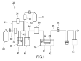
- the adsorption test A1 and the desorption test B1 can be measured using a measuring device 20 shown in FIG. 1.
- the measuring device 20 includes a first tank 30 and a second tank 31.
- the first tank 30 stores dry nitrogen
- the second tank 31 stores a mixed gas of dry nitrogen and dry carbon dioxide.
- the concentration of carbon dioxide in the mixed gas in the second tank 31 is, for example, 5 vol%.
- the measuring device 20 further includes a first container 40 containing water 70, and a first path 60 for sending nitrogen from the first tank 30 to the first container 40.
- the first path 60 has one end connected to the gas outlet of the first tank 30 and the other end disposed in the water 70 of the first container 40.
- the nitrogen sent from the first tank 30 to the first container 40 is humidified by contact with the water 70.
- a mass flow controller 35 is disposed in the first path 60 for adjusting the flow rate of nitrogen sent from the first tank 30 to the first container 40.
- the measuring device 20 further includes a second container 41, a second path 62, and a bypass path 61.
- the second path 62 connects the first container 40 and the second container 41.
- the humidified nitrogen sent to the first container 40 is sent to the second container 41 through the second path 62.
- the bypass path 61 branches off from the first path 60 at a position between the first tank 30 and the mass flow controller 35, and connects to the second path 62.
- a portion of the nitrogen sent from the first tank 30 flows into the bypass path 61 and is sent to the second container 41 through the second path 62.
- a mass flow controller 36 is disposed in the bypass path 61 to adjust the flow rate of the nitrogen sent from the first tank 30 to the bypass path 61.
- the measuring device 20 further includes a third path 63 for sending the mixed gas from the second tank 31 to the second path 62.
- the third path 63 has one end connected to the gas outlet of the second tank 31 and the other end connected to the second path 62.
- a mass flow controller 37 is disposed in the third path 63 for adjusting the flow rate of the mixed gas sent from the second tank 31 to the second path 62.
- the mixed gas sent to the second path 62 is sent to the second container 41 via the second path 62.
- the measuring device 20 further includes a third container 42 and a fourth path 64.
- the third container 42 contains water 71 and an adsorption section 21 disposed in the water 71.
- the adsorption section 21 has a gas inlet 22 and a gas outlet 23.
- the adsorption section 21 functions as a container that contains an acid gas adsorbent therein.
- the adsorption section 21 is configured so that the water 71 does not penetrate into the inside.
- the adsorption section 21 is typically a tube made of a hydrophobic resin, for example, a fluororesin such as tetrafluoroethylene-perfluoroalkoxyethylene copolymer (PFA).
- the tube serving as the adsorption section 21 has an inner diameter of 4 mm and an outer diameter of 6 mm.
- the adsorption section 21 is configured to be detachable from the measuring device 20.
- the measuring device 20 can also be used as an acid gas adsorption device equipped with an adsorption section 21.
- the present invention provides an acid gas adsorption device 20 that includes an adsorption section 21 having a gas inlet 22 and a gas outlet 23, and the adsorption section 21 contains an acid gas adsorbent.
- the fourth path 64 connects the second container 41 and the third container 42. More specifically, the fourth path 64 is connected to the gas inlet 22 of the adsorption section 21 in the third container 42.
- a first concentration meter 50 for measuring the concentration of carbon dioxide in the gas supplied to the adsorption section 21 is disposed in the fourth path 64.
- a CO 2 /H 2 O gas analyzer LI-850-3 manufactured by LI-COR Corporation can be used as the first concentration meter 50.
- the measurement device 20 further includes a fifth path 65 that is connected to the gas outlet 23 of the adsorption unit 21 and is used to discharge gas from the adsorption unit 21 to the outside of the measurement device 20.
- a back pressure valve 55 and a second concentration meter 51 are disposed in the fifth path 65.
- the back pressure valve 55 can adjust the pressure inside the adsorption unit 21 to a constant value.
- the second concentration meter 51 can measure the concentration of carbon dioxide in the gas discharged from the adsorption unit 21.
- a CO 2 /H 2 O gas analyzer LI-850-3 manufactured by LI-COR can be used as the second concentration meter 51.
- each path of the measuring device 20 is made of metal or resin piping.
- an acidic gas adsorbent is prepared and dried.
- the acidic gas adsorbent is used before the heat resistance test and the moist heat resistance test described later.
- the drying process is preferably performed by treating the acidic gas adsorbent for 2 hours or more under a vacuum atmosphere at 60°C.
- the acidic gas adsorbent after the drying process is filled into the adsorption section 21 in a dry room with a dew point of about -60°C.
- the weight of the acidic gas adsorbent filled into the adsorption section 21 is, for example, 50 mg.
- the fourth path 64 and the fifth path 65 are connected to both ends of the adsorption section 21, and the adsorption section 21 is immersed in the water 71 in the third container 42.
- nitrogen from the first tank 30 and the mixed gas from the second tank 31 are supplied to the second container 41 through the first path 60, the second path 62, the bypass path 61, and the third path 63 of the measuring device 20.
- these gases are mixed to obtain a mixed gas G composed of carbon dioxide, nitrogen, and water vapor.
- the concentration of carbon dioxide in the mixed gas G is adjusted to 400 vol ppm.
- the mixed gas G has a temperature of 23° C. and a humidity of 50% RH.
- the mixed gas G is supplied to the adsorption section 21 through the fourth path 64 at a flow rate sufficient for the weight of the acidic gas adsorbent, for example, a flow rate of 300 mL/min for 50 mg of acidic gas adsorbent.
- the pressure of the mixed gas G is adjusted to, for example, 107 kPa by the back pressure valve 55.
- the adsorption section 21 is removed from the third container 42 and immersed in a water bath (not shown) at 80°C for at least two hours.
- the adsorption section 21 is immersed in the water bath until the carbon dioxide concentration measured by the first concentration meter 50 and the carbon dioxide concentration measured by the second concentration meter 51 become substantially the same value. This completes the pretreatment of the acid gas adsorbent in the adsorption section 21.
- the amount of carbon dioxide adsorbed by the acid gas adsorbent within 15 hours from the start is measured, M1.
- the amount of carbon dioxide adsorbed by the acid gas adsorbent can be calculated from the difference between the carbon dioxide concentration measured by the first concentration meter 50 and the carbon dioxide concentration measured by the second concentration meter 51 over time.
- the amount of carbon dioxide adsorbed by 1 g of acid gas adsorbent in 15 hours is calculated based on the amount of substance M1, and the calculated value is specified as the adsorption amount a1.
- desorption test B1 the amount of carbon dioxide desorbed from the acid gas adsorbent within 1.5 hours from the start is measured, M2.
- the amount of carbon dioxide desorbed from the acid gas adsorbent can be calculated from the difference between the carbon dioxide concentration measured by the first concentration meter 50 and the carbon dioxide concentration measured by the second concentration meter 51 over time.
- the amount of carbon dioxide desorbed from 1 g of acid gas adsorbent in 1.5 hours is calculated based on the amount of substance M2, and the calculated value obtained is specified as the desorption amount b1.
- the adsorption amount a1 of carbon dioxide when the adsorption test A1 is performed is preferably 0.4 mmol/g or more, 0.5 mmol/g or more, 0.8 mmol/g or more, 1.0 mmol/g or more, 1.3 mmol/g or more, 1.5 mmol/g or more, 1.8 mmol/g or more, 2.0 mmol/g or more, 2.3 mmol/g or more, 2.4 mmol/g or more, 2.5 mmol/g or more, 2.8 mmol/g or more, 3.0 mmol/g or more, 3.3 mmol/g or more, or even 3.5 mmol/g or more.
- the upper limit of the adsorption amount a1 of carbon dioxide is not particularly limited, and is, for example, 10 mmol/g.
- the amount b1 of carbon dioxide desorption when desorption test B1 is performed is preferably 0.25 mmol/g or more, and may be 0.3 mmol/g or more, 0.5 mmol/g or more, 0.8 mmol/g or more, 1.0 mmol/g or more, 1.3 mmol/g or more, 1.5 mmol/g or more, 1.8 mmol/g or more, 2.0 mmol/g or more, 2.3 mmol/g or more, 2.5 mmol/g or more, 2.8 mmol/g or more, 3.0 mmol/g or more, 3.3 mmol/g or more, or even 3.5 mmol/g or more.
- the upper limit of the amount b1 of carbon dioxide desorption is not particularly limited and may be, for example, 10 mmol/g.
- the ratio of the desorption amount b1 (mmol/g) to the adsorption amount a1 (mmol/g) (65°C desorption rate) is, for example, 40% or more, and may be 45% or more, 50% or more, 60% or more, 70% or more, 80% or more, 90% or more, 95% or more, 96% or more, or even 97% or more, or may be 100%.
- the present invention provides An acidic gas adsorbent comprising a polymer P having an amino group, The density of nitrogen element in the acid gas adsorbent is greater than 12.0 mmol/g;
- the adsorption amount a1 of carbon dioxide is 0.35 mmol/g or more
- the present invention provides an acidic gas adsorbent having a ratio (65°C desorption rate) of the amount b1 (mmol/g) of carbon dioxide desorption when the above-mentioned desorption test B1 is carried out to the amount a1 (mmol/g) of adsorption, of 40% or more.
- the 65° C. desorption rate may be within the range exemplified above, and in particular may be 50% or more.
- the amount b2 of carbon dioxide desorbed is preferably 0.2 mmol/g or more.
- Desorption test B2 While continuing to supply the mixed gas G to the container (the adsorption section 21) containing the acidic gas adsorbent, the acidic gas adsorbent after the adsorption test A1 is heated at 50°C for 1.5 hours.
- the desorption test B2 can be performed in the same manner as the desorption test B1 described above, except that the adsorption section 21 is immersed in a water bath at 50°C.
- the amount b2 of carbon dioxide desorption when the desorption test B2 is performed is preferably 0.25 mmol/g or more, and may be 0.3 mmol/g or more, 0.5 mmol/g or more, 0.8 mmol/g or more, 1.0 mmol/g or more, 1.3 mmol/g or more, 1.5 mmol/g or more, 1.8 mmol/g or more, 2.0 mmol/g or more, or even 2.3 mmol/g or more.
- the upper limit of the amount b2 of carbon dioxide desorption is not particularly limited, and is, for example, 10 mmol/g.
- the ratio of the desorption amount b2 (mmol/g) to the adsorption amount a1 (mmol/g) (50°C desorption rate) is, for example, 40% or more, and may be 45% or more, 50% or more, 60% or more, 70% or more, 80% or more, or even 90% or more.
- the upper limit of the 50°C desorption rate is not particularly limited and is, for example, 99%.
- the adsorption amount a2 of carbon dioxide is preferably 0.05 mmol/g or more.
- the adsorption amount a2 can be used as an index of the rate at which the acidic gas is adsorbed. In other words, it can be said that the larger the adsorption amount a2, the faster the acidic gas adsorbent adsorbs the acidic gas.
- Adsorption test A2 The mixed gas G is continuously fed into the container (the above-mentioned adsorption section 21) containing the acid gas adsorbent for one hour.
- the adsorption test A2 can be performed in the same manner as the adsorption test A1, except that the test time is changed from 15 hours to 1 hour.
- the amount a2 of carbon dioxide adsorption when the adsorption test A2 is performed is preferably 0.1 mmol/g or more, and may be 0.2 mmol/g or more, 0.3 mmol/g or more, 0.4 mmol/g or more, 0.5 mmol/g or more, 0.6 mmol/g or more, 0.7 mmol/g or more, 0.8 mmol/g or more, 0.9 mmol/g or more, 1.0 mmol/g or more, 1.1 mmol/g or more, or even 1.2 mmol/g or more.
- the upper limit of the amount a2 of carbon dioxide adsorption is not particularly limited, and may be, for example, 5 mmol/g.
- the adsorption amount a3 of carbon dioxide is preferably 0.1 mmol/g or more.
- the adsorption amount a3 can also be used as an index of the rate at which the acidic gas is adsorbed. In other words, it can be said that the larger the adsorption amount a3, the faster the acidic gas adsorbent adsorbs the acidic gas.
- Adsorption test A3 The mixed gas G was continuously fed into the vessel (the adsorption section 21 described above) containing the acidic gas adsorbent for 4 hours.
- the adsorption test A3 can be performed in the same manner as the adsorption test A1, except that the test time is changed from 15 hours to 4 hours.
- the amount a3 of adsorption of carbon dioxide when the adsorption test A3 is performed is preferably 0.3 mmol/g or more, and may be 0.5 mmol/g or more, 0.8 mmol/g or more, 1.0 mmol/g or more, 1.3 mmol/g or more, 1.5 mmol/g or more, 1.8 mmol/g or more, 1.9 mmol/g or more, 2.0 mmol/g or more, or even 2.3 mmol/g or more.
- the upper limit of the amount a3 of adsorption of carbon dioxide is not particularly limited, and is, for example, 5 mmol/g.
- the acidic gas adsorbent of the present embodiment preferably has high heat resistance.
- the heat resistance of the acidic gas adsorbent can be evaluated by performing a heat resistance test on the acidic gas adsorbent.
- the heat resistance test can be performed by subjecting the acidic gas adsorbent to a heat treatment for 100 hours in an environment of 85 ° C. and 10% RH. As an example, when the acidic gas adsorbent is subjected to a heat treatment for 100 hours in an environment of 85 ° C.
- the maintenance rate R1 of the amount of adsorbable carbon dioxide (mmol / g) may be, for example, 30% or more, 40% or more, 50% or more, 60% or more, 70% or more, 80% or more, 85% or more, 90% or more, 92% or more, 94% or more, 95% or more, or even 96% or more.
- the upper limit of the maintenance rate R1 is not particularly limited and is, for example, 99%.
- the retention rate R1 can be specified in detail by the following method. First, in a dry room with a dew point of about -60 ° C., the acidic gas adsorbent is placed in a glass container (for example, a lablan screw tube bottle manufactured by AS ONE Corporation). Next, the glass container is set in a thermostatic chamber (for example, PSL-2J manufactured by ESPEC Corporation) and heat-treated in air at 85 ° C. and 10% RH for 100 hours. Next, the acidic gas adsorbent after the heat treatment is set in a vacuum dryer (for example, VOS-310C manufactured by EYELA Corporation) in the dry room and treated for 2 hours or more under a vacuum atmosphere at 60 ° C.
- a vacuum dryer for example, VOS-310C manufactured by EYELA Corporation
- the amount a4 of carbon dioxide adsorption is, for example, 0.35 mmol/g or more, 0.4 mmol/g or more, 0.5 mmol/g or more, 0.8 mmol/g or more, 1.0 mmol/g or more, 1.3 mmol/g or more, 1.5 mmol/g or more, 1.8 mmol/g or more, 2.0 mmol/g or more, 2.3 mmol/g or more, 2.4 mmol/g or more, 2.5 mmol/g or more, 2.8 mmol/g or more, 3.0 mmol/g or more, 3.3 mmol/g or more, or even 3.5 mmol/g or more.
- the upper limit of the amount a4 of carbon dioxide adsorption is not particularly limited and may be, for example, 10 mmol/g.
- the acidic gas adsorbent of the present embodiment preferably has high resistance to moist heat.
- the resistance of the acidic gas adsorbent to moist heat can be evaluated by carrying out a moist heat resistance test on the acidic gas adsorbent.
- the moist heat resistance test can be carried out by carrying out a heat treatment for 100 hours on the acidic gas adsorbent in an environment of 85°C and 85% RH.
- the maintenance rate R2 of the amount of adsorbable carbon dioxide (mmol/g) may be, for example, 30% or more, 40% or more, 50% or more, 60% or more, 70% or more, 80% or more, 85% or more, 90% or more, 95% or more, or even 96% or more.
- the upper limit of the maintenance rate R2 is not particularly limited, and is, for example, 99%.
- the retention rate R2 can be specified in detail by the following method. First, in a dry room with a dew point of about -60 ° C., the acidic gas adsorbent is placed in a glass container (for example, a lablan screw tube bottle manufactured by AS ONE Corporation). Next, the glass container is set in a thermostatic chamber (for example, PSL-2J manufactured by ESPEC Corporation) and heat-treated in air at 85 ° C. and 85% RH for 100 hours. Next, the acidic gas adsorbent after the heat treatment is set in a vacuum dryer (for example, VOS-310C manufactured by EYELA Corporation) in the dry room and treated under a vacuum atmosphere at 60 ° C. for 2 hours or more.
- a vacuum dryer for example, VOS-310C manufactured by EYELA Corporation
- the carbon dioxide adsorption amount a5 when the above-mentioned adsorption test A1 is performed on the acidic gas adsorbent after the treatment is measured.
- the retention rate R2 Based on the obtained adsorption amount a5 and the carbon dioxide adsorption amount a1 when the adsorption test A1 is performed on the acidic gas adsorbent before the moist heat resistance test, the retention rate R2 can be calculated by the following formula.
- Maintenance rate R2 (%) adsorption amount a5 (mmol/g) ⁇ adsorption amount a1 (mmol/g) x 100
- the amount a5 of carbon dioxide adsorption is, for example, 0.35 mmol/g or more, 0.4 mmol/g or more, 0.5 mmol/g or more, 0.8 mmol/g or more, 1.0 mmol/g or more, 1.3 mmol/g or more, 1.5 mmol/g or more, 1.8 mmol/g or more, 2.0 mmol/g or more, 2.3 mmol/g or more, 2.4 mmol/g or more, 2.5 mmol/g or more, 2.8 mmol/g or more, 3.0 mmol/g or more, 3.3 mmol/g or more, or even 3.5 mmol/g or more.
- the upper limit of the amount a5 of carbon dioxide adsorption is not particularly limited and may be, for example, 10 mmol/g.
- the polymer P In the acidic gas adsorbent, the polymer P has a function of adsorbing acidic gas due to the amino group.
- the polymer P preferably contains at least one selected from the group consisting of a primary amino group, a secondary amino group, and a tertiary amino group as the amino group. From the viewpoint of the adsorption property of the acidic gas, the polymer P preferably contains at least one selected from the group consisting of a primary amino group and a secondary amino group, and preferably contains both a primary amino group and a secondary amino group.
- the acidic gas adsorbent tends to be able to easily desorb the adsorbed acidic gas.
- the regeneration treatment of the acidic gas adsorbent can be performed under relatively mild conditions.
- the polymer P may contain a tertiary amino group, but does not necessarily have to contain a tertiary amino group.
- the ratio I A /I B of the peak intensity I A of the absorption peak existing near the wave number 4930 cm -1 to the peak intensity I B of the absorption peak existing near the wave number 6500 cm -1 is preferably 0.80 or more.
- the polymer P contains a primary amino group and a secondary amino group, an absorption peak derived from the primary amino group and the secondary amino group is observed near the wave number 6500 cm -1 , and an absorption peak derived from the primary amino group is observed near the wave number 4930 cm -1 .
- the above ratio I A /I B can be used as an index regarding the ratio of the substance amount of the primary amino group to the substance amount of the secondary amino group in the polymer P.
- NIR can be performed using a transparent test piece obtained by press-molding the polymer P. In this test piece, light scattering that can affect the results of NIR tends to be less likely to occur.
- the ratio I A / IB is more preferably 0.90 or more, and may be 0.95 or more, 1.00 or more, 1.05 or more, 1.10 or more, 1.15 or more, or even 1.20 or more.
- the upper limit of the ratio I A / IB is not particularly limited, and is, for example, 1.50 or less.
- the weight ratio of the nitrogen element in the polymer P is, for example, 5 wt% or more, and preferably 10 wt% or more. The higher this weight ratio, the more the acid gas adsorption ability of the acid gas adsorbent tends to improve.
- the upper limit of the weight ratio of the nitrogen element in the polymer P is not particularly limited, and is, for example, 30 wt%. Note that when all the nitrogen elements contained in the polymer P are derived from amino groups, the above weight ratio of the nitrogen element can be regarded as the weight ratio of the amino groups in the polymer P.
- the density of the nitrogen element in the polymer P is, for example, greater than 12.0 mmol/g, preferably 12.2 mmol/g or more, and may be 12.5 mmol/g or more, 13.0 mmol/g or more, 13.5 mmol/g or more, 14.0 mmol/g or more, 14.5 mmol/g or more, 15.0 mmol/g or more, 15.5 mmol/g or more, 16.0 mmol/g or more, 16.5 mmol/g or more, 17.0 mmol/g or more, or even 17.5 mmol/g or more.
- the upper limit of the density of the nitrogen element is not particularly limited, and may be, for example, 30 mmol/g or 20 mmol/g.
- the density of the nitrogen element in the polymer P means the amount of substance of the nitrogen element contained in 1 g of the polymer P, and can be measured by the same method as the density d of the nitrogen element in the acidic gas adsorbent described above.
- the density of the nitrogen element can be regarded as the density of the amino groups in the polymer P.
- the polymer P may contain other functional groups besides amino groups. Examples of other functional groups include hydroxyl groups, ether groups, ester groups, and amide groups. It is preferable that the polymer P contains an ether group as the other functional group.
- the polymer P is preferably an amine polymer, in particular an amine polymer containing a structural unit U1 derived from an epoxy monomer.
- This amine polymer may contain a reactant P1 of a compound group containing an amine monomer, in particular a compound group containing an amine monomer and an epoxy monomer.
- the group of compounds for forming the reactant P1 includes an amine monomer and an epoxy monomer.
- the reactant P1 may be a polymer of a monomer group including an amine monomer and an epoxy monomer (particularly a polymer of an amine monomer and an epoxy monomer).
- the reactant P1 may be a crosslinked product of an amine monomer with an epoxy monomer.
- the crosslinked product of an amine monomer with an epoxy monomer not only tends to have a high density of nitrogen elements, but also tends to have high heat resistance and moist heat resistance.
- at least one selected from the group consisting of the amine monomer and the epoxy monomer is a multifunctional monomer having two or more functionalities, particularly three or more functionalities.
- the amine monomer is a monomer containing at least one amino group, and preferably contains at least one primary amino group.
- the number of primary amino groups contained in the amine monomer is preferably 2 or more, may be 3 or more, or may be 4 or more.
- the upper limit of the number of primary amino groups is not particularly limited, and may be, for example, 100, or 10.
- the amine monomer may contain secondary amino groups or tertiary amino groups in addition to the primary amino groups, but may not contain tertiary amino groups.
- the ratio of the number of primary amino groups to the number of all amino groups is not particularly limited, and may be, for example, 10% or more, preferably 20% or more, more preferably 30% or more, or may be 40% or more.
- the upper limit of this ratio is not particularly limited, and may be, for example, 80% or 60%.
- the molecular weight (weight average molecular weight in some cases) of the amine monomer is, for example, 50 or more, and may be 100 or more, 150 or more, 200 or more, 300 or more, 500 or more, 1000 or more, or even 1500 or more.
- the larger the molecular weight of the amine monomer the easier it is to adjust the density of the nitrogen element in the reactant P1. Furthermore, amine monomers with larger molecular weights tend to be safer to handle.
- the upper limit of the molecular weight of the amine monomer may be, for example, 5000, or 2000 or less.
- the molecular weight of the amine monomer may be less than 1000, 500 or less, or even 300 or less in some cases.
- the amine equivalent of the amine monomer is, for example, 10 g/eq. or more, preferably 20 g/eq. or more, and more preferably 30 g/eq. or more.
- the upper limit of the amine equivalent of the amine monomer is not particularly limited, and may be, for example, 200 g/eq. It may be 150 g/eq. or less, 100 g/eq. or less, or even 50 g/eq. or less.
- the amine equivalent means the mass of the amine monomer relative to 1 equivalent of active hydrogen of the primary amino group contained in the amine monomer.
- the number of structural units contained in the amine monomer degree of polymerization
- Amine monomers include, for example, ethylamine, ethylenediamine, 1,4-butylenediamine, 1,5-pentanediamine, 1,6-hexanediamine, 1,7-heptanediamine, 1,8-octanediamine, diethylenetriamine, triethylenetetramine, tetraethylenepentamine, pentaethylenehexamine, hexaethyleneheptamine, iminobispropylamine, bis(hexamethylene)triamine, 1,3,6-trisaminomethylhexane, tris(2-aminoethyl)amine, N,N'-bis(3-aminopropyl)ethylenediamine, polymethylenediamine, trimethylhexamethylenediamine, polyethersulfones, Aliphatic amines such as tertiamine; alicyclic amines such as isophoronediamine, menthanediamine, piperazine, N-aminoethylpiperazine, 3,9
- the amine monomer preferably contains an aliphatic amine (particularly triethylenetetramine (TETA)) or an aliphatic polyamine (particularly polyethyleneimine (PEI)).
- TETA triethylenetetramine
- PEI polyethyleneimine
- the amine monomers can be used alone or in combination of two or more.
- aliphatic polyamines tend to be safer to handle.
- amine monomers such as aliphatic polyamines are preferably not classified as hazardous materials under the Fire Service Act, and are preferably not subject to the Poisonous and Deleterious Substances Control Act. It is preferable that the result of a mutagenicity test (Ames test) for the amine monomer is negative. It is preferable that the result of a skin irritation test (primary skin irritation test using rabbits) for the amine monomer is a mild or moderate irritant.
- the epoxy monomer is a monomer containing at least one epoxy group.
- the number of epoxy groups contained in the epoxy monomer is preferably 2 or more, and may be 3 or more, or 4 or more. The greater the number of epoxy groups, the greater the number of crosslinking points in the epoxy monomer and the denser the crosslinking structure in the reactant P1, which tends to improve heat resistance and moist heat resistance.
- the upper limit of the number of epoxy groups contained in the epoxy monomer is not particularly limited and is, for example, 10.
- the molecular weight of the epoxy monomer is not particularly limited, and is, for example, less than 1000, and preferably 500 or less.
- the epoxy equivalent of the epoxy monomer is not particularly limited, and is, for example, 150 g/eq. or less, and preferably 100 g/eq. or less.
- the lower limit of the epoxy equivalent of the epoxy monomer is not particularly limited, and is, for example, 50 g/eq.
- the epoxy equivalent means the mass of the epoxy monomer per equivalent of the epoxy group contained in the epoxy monomer.
- Epoxy monomers include, for example, monofunctional epoxy compounds such as n-butyl glycidyl ether, higher alcohol glycidyl ether, allyl glycidyl ether, 2-ethylhexyl glycidyl ether, phenyl glycidyl ether, cresyl glycidyl ether, p-sec-butylphenyl glycidyl ether, and t-butylphenyl glycidyl ether; diepoxy alkanes such as 1,5-hexadiene diepoxide, 1,7-octadiene diepoxide, and 1,9-decadiene diepoxide; (poly)ethylene glycol diglycidyl ether, (poly)propylene glycol diglycidyl ether, and (poly)propylene glycol diglycidyl ether.
- monofunctional epoxy compounds such as n-butyl glycidyl
- polyfunctional epoxy compounds include those having an ether group such as ethylene glycol diglycidyl ether, 1,4-butanediol diglycidyl ether, neopentyl glycol diglycidyl ether, 1,6-hexanediol diglycidyl ether, trimethylolpropane polyglycidyl ether, pentaerythritol polyglycidyl ether, and sorbitol polyglycidyl ether; and those having an amino group such as N,N,N',N'-tetraglycidyl metaxylenediamine and 1,3-bis(N,N-diglycidylaminomethyl)cyclohexane.
- an ether group such as ethylene glycol diglycidyl ether, 1,4-butanediol diglycidyl ether, neopentyl glycol diglycidyl ether, 1,6-hexanediol digly
- the epoxy monomer may be an aromatic epoxy resin, a non-aromatic epoxy resin, etc., depending on the case.
- aromatic epoxy resins include polyphenyl-based epoxy resins, epoxy resins containing a fluorene ring, epoxy resins containing triglycidyl isocyanurate, and epoxy resins containing a heteroaromatic ring (e.g., a triazine ring).
- polyphenyl-based epoxy resins examples include bisphenol A-type epoxy resins, brominated bisphenol A-type epoxy resins, bisphenol F-type epoxy resins, bisphenol AD-type epoxy resins, stilbene-type epoxy resins, biphenyl-type epoxy resins, bisphenol A novolac-type epoxy resins, cresol novolac-type epoxy resins, diaminodiphenylmethane-type epoxy resins, and tetrakis(hydroxyphenyl)ethane-based epoxy resins.
- non-aromatic epoxy resins examples include aliphatic glycidyl ether-type epoxy resins, aliphatic glycidyl ester-type epoxy resins, alicyclic glycidyl ether-type epoxy resins, alicyclic glycidyl amine-type epoxy resins, and alicyclic glycidyl ester-type epoxy resins.
- the epoxy monomers can be used alone or in combination of two or more. When a monofunctional epoxy compound is used, it is preferable to use it in combination with another epoxy monomer containing two or more epoxy groups.
- the monofunctional epoxy compound can also be used as a reactive diluent to adjust the viscosity of the compound group for forming the reactant P1.
- the epoxy monomer preferably contains a multifunctional epoxy compound having an ether group, such as ethylene glycol diglycidyl ether (EDE) or pentaerythritol tetraglycidyl ether (PETG). EDE or PETG has a small epoxy equivalent and can easily lower the glass transition temperature Tg of the polymer P. These epoxy compounds also tend to be low in cost.
- the epoxy monomer may contain a multifunctional epoxy compound having an amino group, such as N,N,N',N'-tetraglycidyl metaxylenediamine or 1,3-bis(N,N-diglycidylaminomethyl)cyclohexane, in addition to or instead of the multifunctional epoxy compound having an ether group.
- the polymer P as an amine polymer may contain a structural unit U1 derived from an epoxy monomer.
- the polymer P is a reactant P1
- the polymer P further contains a structural unit U2 derived from an amine monomer.
- the content of the structural unit U1 in the polymer P, particularly the reactant P1 is, for example, 20 wt % to 70 wt %.
- the content of the structural unit U2 in the polymer P, particularly the reactant P1 is, for example, 30 wt % or more, preferably 50 wt % or more.
- the upper limit of the content of the structural unit U2 is not particularly limited, and is, for example, 80 wt %.
- the glass transition temperature Tg of the polymer P is not particularly limited, and may be, for example, 40 ° C. or less, 30 ° C. or less, 20 ° C. or less, 15 ° C. or less, 10 ° C. or less, 5 ° C. or less, 0 ° C. or less, -1 ° C. or less, less than -1 ° C., -2 ° C. or less, -3 ° C. or less, -4 ° C. or less, -5 ° C. or less, -6 ° C. or less, -7 ° C. or less, -8 ° C. or less, -9 ° C. or less, -10 ° C. or less, -11 ° C.
- the lower the glass transition temperature Tg of the polymer P the higher the rate at which the acidic gas is adsorbed in the acidic gas adsorbent.
- the lower limit of the glass transition temperature Tg of the polymer P may be, for example, -100 ° C. or more, -50 ° C. or more, -30 ° C. or more, or even -20 ° C. or more, from the viewpoint of sufficiently ensuring the adsorption of the acidic gas in the acidic gas adsorbent, the viewpoint of heat resistance, and the viewpoint of ease of preparation of the acidic gas adsorbent.
- the glass transition temperature Tg means the midpoint glass transition temperature (T mg ) determined in accordance with the provisions of JIS K7121:1987.
- the polymer P generally corresponds to a thermosetting resin.
- the polymer P is preferably solid at 25°C, preferably in the range of 25°C to 80°C.
- the weight average molecular weight of polymer P is not particularly limited, and is, for example, 500 or more, preferably 1000 or more, more preferably 10000 or more, and even more preferably 100000 or more.
- the upper limit of the weight average molecular weight of polymer P is, for example, 10,000,000.
- the acidic gas adsorbent preferably contains polymer P as a main component.
- "main component” means the component contained in the acidic gas adsorbent in the largest amount by weight.
- the content of polymer P in the acidic gas adsorbent is, for example, 50 wt% or more, preferably 70 wt% or more, more preferably 90 wt% or more, and may be 95 wt% or more, or may be 99 wt% or more.
- the acidic gas adsorbent may be substantially composed of polymer P only. The higher the content of polymer P, the more the acidic gas adsorbent tends to improve its ability to adsorb acidic gases.
- the acidic gas adsorbent may be substantially composed of only the polymer P, but may further contain other components other than the polymer P.
- the other components include reaction accelerators, plasticizers, pigments, dyes, antioxidants, conductive materials, antistatic agents, UV absorbers, flame retardants, and antioxidants.
- the reaction accelerators can be used when synthesizing the polymer P.
- the reaction accelerators include tertiary amines such as triethylamine and tributylamine; and imidazoles such as 2-phenol-4-methylimidazole, 2-ethyl-4-methylimidazole, and 2-phenol-4,5-dihydroxyimidazole. These reaction accelerators can accelerate the reaction for synthesizing the reactant P1.
- the weight ratio of the nitrogen element in the acidic gas adsorbent is, for example, 5 wt% or more, and preferably 10 wt% or more. The higher this weight ratio, the more the acidic gas adsorbent tends to improve its ability to adsorb acidic gases.
- the upper limit of the weight ratio of the nitrogen element in the acidic gas adsorbent is not particularly limited, and is, for example, 30 wt%. Note that when all the nitrogen elements contained in the acidic gas adsorbent are derived from amino groups, the weight ratio of the nitrogen element described above can be regarded as the weight ratio of the amino groups in the acidic gas adsorbent.
- the shape of the acid gas adsorbent is not particularly limited, and may be, for example, a block, sheet, or particulate shape.
- particulate shape includes spherical, ellipsoidal, scaly, fibrous, and other shapes.
- the acidic gas adsorbent may have a porous structure.
- the acidic gas adsorbent may include a porous body S containing a polymer P.
- the porous body S is typically composed of only the polymer P.
- the shape of the porous body S may be, for example, a block shape, a sheet shape, or a particle shape.
- the acidic gas adsorbent may or may not include a porous resin sheet as the porous body S.
- the acidic gas adsorbent may or may not include a member other than the porous body S, such as a carrier for supporting the polymer P. When the acidic gas adsorbent does not include a carrier, the shape of the acidic gas adsorbent tends to be easily adjustable by cutting or machining.
- the porous body S preferably has a three-dimensional mesh skeleton composed of polymer P.
- the three-dimensional mesh skeleton may contain polymer P as a main component, or may contain substantially only polymer P.
- the three-dimensional mesh skeleton may further contain other components besides polymer P.
- the above three-dimensional mesh skeleton extends continuously.
- the pores contained in the porous body S are, for example, continuous pores formed continuously in a three-dimensional shape.
- the porous body S may have independent pores, or may have through holes penetrating the porous body S.
- the specific surface area of the acidic gas adsorbent is not particularly limited, and may be, for example, 0.5 m 2 /g or more, 1.0 m 2 /g or more, 2.0 m 2 /g or more, 3.0 m 2 /g or more, 4.0 m 2 /g or more, 5.0 m 2 /g or more, 6.0 m 2 /g or more, 7.0 m 2 /g or more, 8.0 m 2 /g or more, or even 9.0 m 2 /g or more.
- the larger the specific surface area of the acidic gas adsorbent the higher the rate at which the acidic gas adsorbent adsorbs the acidic gas.
- the upper limit of the specific surface area of the acidic gas adsorbent is not particularly limited, and may be, for example, 100 m 2 /g.
- the specific surface area of the acidic gas adsorbent means the BET (Brunauer-Emmett-Teller) specific surface area by nitrogen gas adsorption.
- the specific surface area of the acidic gas adsorbent can be measured by a method conforming to the provisions of JIS Z8830:2013.
- the present invention provides An acidic gas adsorbent comprising a polymer P having an amino group,
- the density d of the nitrogen element in the acidic gas adsorbent is greater than 12.0 mmol/g;
- the specific surface area of the acid gas adsorbent is 0.5 m 2 /g or more;
- the acid gas adsorbent is provided, in which the glass transition temperature of the polymer P is 40° C. or lower.
- the acidic gas adsorbent has the above-mentioned adsorption and desorption characteristics for carbon dioxide.
- the adsorption amounts a1 to a3, the desorption amounts b1 to b2, the 50° C. desorption rate, the 65° C. desorption rate, and the like of the acidic gas adsorbent measured by the above-mentioned methods may satisfy the above-mentioned ranges.
- the pore volume of the acidic gas adsorbent is not particularly limited, and may be, for example, 0.1 cm 3 /g or more, 0.2 cm 3 /g or more, 0.3 cm 3 /g or more, 0.5 cm 3 /g or more, 1.0 cm 3 /g or more, or even 2.0 cm 3 /g or more.
- the upper limit of the pore volume of the acidic gas adsorbent is not particularly limited, and may be, for example, 5.0 cm 3 /g, 4.0 cm 3 /g, or 3.0 cm 3 /g.
- the pore volume of the acidic gas adsorbent can be measured by mercury intrusion porosimetry. The mercury intrusion porosimetry is performed under the condition of an initial pressure of 21 kPa using a commercially available pore distribution analyzer (for example, Autopore V9620 manufactured by Micromeritics).
- the average pore diameter of the acidic gas adsorbent is not particularly limited, and may be, for example, 0.1 ⁇ m or more, 0.2 ⁇ m or more, 0.3 ⁇ m or more, or even 0.5 ⁇ m or more.
- the upper limit of the average pore diameter of the acidic gas adsorbent is not particularly limited, and may be, for example, 50 ⁇ m.
- the average pore diameter of the acidic gas adsorbent means the median diameter measured by mercury intrusion porosimetry.
- the mercury intrusion porosimetry is performed using a commercially available pore distribution analyzer (for example, Autopore V9620 manufactured by Micromeritics) under conditions of an initial pressure of 21 kPa.
- the average particle size of the acidic gas adsorbent is not particularly limited, and is, for example, 0.5 ⁇ m or more, preferably 1 ⁇ m or more, and may be 10 ⁇ m or more, 20 ⁇ m or more, or 30 ⁇ m or more.
- the average particle size of the acidic gas adsorbent may be 200 ⁇ m or less, 100 ⁇ m or less, or less than 75 ⁇ m.
- the average particle size of the acidic gas adsorbent means the particle size (d50) corresponding to 50% cumulative volume in the particle size distribution measured by a laser diffraction particle sizer or the like.
- the method for producing an acidic gas adsorbent of the present embodiment preferably includes reacting a compound group including an amine monomer having a primary amino group to synthesize a polymer P.
- the compound group preferably further includes an epoxy monomer having an epoxy group.
- the compound group may contain only epoxy monomer E1 containing two epoxy groups, or may contain epoxy monomer E2 containing three or more, for example, four, epoxy groups instead of or together with epoxy monomer E1.
- the weight ratio E1/E2 of epoxy monomer E1 to epoxy monomer E2 is not particularly limited and may be, for example, 3/7 to 8/2, 3/7 to 5/5, or even 3/7 to 4/6.
- the ratio E/A of the equivalent E of the epoxy group in the compound group to the equivalent A of the active hydrogen of the primary amino group in the compound group is preferably 1.00 or less.
- the mixing ratio of the amine monomer and the epoxy monomer is preferably adjusted so that the ratio E/A is 1.00 or less.
- the ratio E/A is preferably 0.90 or less, and may be 0.50 or less, less than 0.50, 0.45 or less, 0.40 or less, 0.35 or less, or even 0.30 or less.
- the smaller the ratio E/A the higher the ratio of the primary amino group in the polymer P and the higher the density d of the nitrogen element in the acidic gas adsorbent.
- the lower limit of the ratio E/A is, for example, 0.10 or more, and may be 0.15 or more, or even 0.20 or more, from the viewpoint of ease of preparation of the acidic gas adsorbent.
- the reaction of the compound group can be carried out by applying energy to the compound group.
- the energy applied to the compound group is preferably thermal energy.
- the reaction of the compound group can be promoted by heating the compound group at a temperature of 40°C to 100°C.
- the energy applied to the compound group may be light energy.
- the acidic gas adsorbent having a porous structure can be produced by the following method. First, the above-mentioned compound group is mixed with a porogen to produce a mixed liquid.
- the porogen is a solvent that can dissolve the monomers contained in the compound group and can cause reaction-induced phase separation after the compound group reacts.
- porogen examples include cellosolves such as methyl cellosolve and ethyl cellosolve, esters such as ethylene glycol monomethyl ether acetate and propylene glycol monomethyl ether acetate, glycols such as polyethylene glycol, polypropylene glycol, polybutylene glycol, and polyoxyalkylene glycol, and ethers such as polyoxyethylene monomethyl ether and polyoxyethylene dimethyl ether.
- the polyoxyalkylene glycol include poly(1,2-butanediol)-6 propylene glycol and polyoxypropylene diglyceryl ether.
- the porogen may be a polar solvent such as ethyl acetate, N,N-dimethylformamide (DMF), acetonitrile, ethanol, isopropanol, or a nonpolar solvent such as toluene, or a mixture of these solvents.
- a polar solvent such as ethyl acetate, N,N-dimethylformamide (DMF), acetonitrile, ethanol, isopropanol, or a nonpolar solvent such as toluene, or a mixture of these solvents.
- the porogens can be used alone or in combination of two or more.
- the mixture may further contain components other than the compound group.
- the other components include the reaction accelerators described above.
- the compound group is reacted in the mixture.
- the compound group is reacted by filling a mold with the mixture and then performing a heat treatment. This results in a cured body containing the polymer P and the porogen. In this cured body, the polymer P and the porogen undergo phase separation to form a co-continuous structure.
- the porogen is extracted and removed from the hardened body. This makes it possible to obtain an acid gas adsorbent having a porous structure.
- the porogen can be extracted by immersing the hardened body in a solvent.
- the solvent that can be used include water, aliphatic hydrocarbon solvents, aromatic hydrocarbon solvents, aliphatic alcohol solvents, ester solvents, ether solvents, and halogen-containing organic solvents.
- aliphatic hydrocarbon solvents include n-hexane, cyclohexane, methylcyclohexane, n-heptane, n-octane, isooctane, petroleum ether, and benzine.
- aromatic hydrocarbon solvents include toluene, xylene, mesitylene, and benzene.
- aliphatic alcohol solvents include methanol, ethanol, isopropanol, butanol, cyclohexanol, ethylene glycol, propylene glycol, propylene glycol monomethyl ether, and diethylene glycol.
- ester solvents include ethyl acetate.
- ether solvents include diethyl ether, diisopropyl ether, dibutyl ether, ethylene glycol dimethyl ether, ethylene glycol diethyl ether, propylene glycol dimethyl ether, propylene glycol diethyl ether, diethylene glycol dimethyl ether, tetrahydrofuran, dioxane, anisole, etc.
- halogen-containing organic solvents include dichloromethane, chloroform, carbon tetrachloride, dichloroethane, chlorobenzene, etc. These solvents can be used alone or in combination of two or more.
- an acidic gas adsorbent with a large specific surface area can be prepared.
- the reaction rate of the compound group varies depending on the type and blending ratio of the monomers contained in the compound group. As an example, the reaction rate of the compound group tends to be high when epoxy monomer E2 containing three or more, for example four, epoxy groups is used, or when polyethyleneimine with a large weight average molecular weight is used as the amine monomer.
- the acidic gas adsorbent of the present embodiment can adsorb acidic gases, such as carbon dioxide, hydrogen sulfide, carbonyl sulfide, sulfur oxides (SOx), hydrogen cyanide, and nitrogen oxides (NOx), and is preferably carbon dioxide.
- acidic gases such as carbon dioxide, hydrogen sulfide, carbonyl sulfide, sulfur oxides (SOx), hydrogen cyanide, and nitrogen oxides (NOx)
- the acid gas adsorbent can be used by the following method. First, a mixed gas containing an acid gas is contacted with the acid gas adsorbent.
- the mixed gas preferably contains other gases in addition to the acid gas. Examples of the other gases include non-polar gases such as hydrogen and nitrogen, and inert gases such as helium, and nitrogen is preferred.
- the mixed gas is typically air.
- the mixed gas may be off-gas from a chemical plant or a thermal power plant.
- the temperature of the mixed gas is, for example, room temperature (23°C).
- the concentration of the acidic gas in the mixed gas is not particularly limited, and is, for example, 0.01 vol% (100 volppm) or more, preferably 0.04 vol% (400 volppm) or more, and may be 1.0 vol% or more, under standard conditions (0°C, 101 kPa).
- the upper limit of the carbon dioxide concentration in the mixed gas is not particularly limited, and is, for example, 10 vol% under standard conditions.
- the pressure of the mixed gas is typically equal to the atmospheric pressure in the environment in which the acidic gas adsorbent is used. However, the mixed gas to be contacted with the acidic gas adsorbent may be pressurized.
- the acid gas adsorbent that comes into contact with the mixed gas adsorbs the acid gas contained in the mixed gas.
- the operation of bringing the mixed gas into contact with the acid gas adsorbent is preferably carried out until the adsorption of the acid gas by the acid gas adsorbent reaches equilibrium.
- the acid gas adsorbent that has adsorbed the acid gas is regenerated.
- the regeneration can be performed by heating the acid gas adsorbent.
- the heating temperature of the acid gas adsorbent is, for example, 50 to 80°C.
- the acid gas adsorbent may be heated under a reduced pressure or vacuum.
- the acid gas, particularly carbon dioxide, desorbed from the acid gas adsorbent can be used as a raw material for chemical synthesis or dry ice.
- the adsorption of acid gas by the acid gas adsorbent and the regeneration of the acid gas adsorbent can be performed using the measurement device 20 (acid gas adsorption device) described above.
- the structure 15 of this embodiment includes the above-mentioned acidic gas adsorbent 10 and a ventilation path 14.
- the structure 15 is typically a honeycomb structure having a plurality of ventilation paths 14 extending in the same direction.
- the acid gas adsorbent 10 provided in the structure 15 typically has a sheet shape.
- the structure 15 may include a support that supports the acid gas adsorbent 10 together with the acid gas adsorbent 10, or may not include a support.
- the structure 15 preferably includes an adsorbent unit U in which a corrugated acidic gas adsorbent 10A and a flat-plate-shaped acidic gas adsorbent 10B are stacked.
- a corrugated acidic gas adsorbent 10A and a flat-plate-shaped acidic gas adsorbent 10B are stacked.
- the acidic gas adsorbent 10A a plurality of peaks 12 and a plurality of valleys 13 are alternately arranged.
- An air passage 14 is formed between the peaks 12 or valleys 13 of the acidic gas adsorbent 10A and the acidic gas adsorbent 10B.
- the direction x is the direction (wave direction) in which the plurality of peaks 12 and the plurality of valleys 13 of the acidic gas adsorbent 10A are alternately arranged.
- the direction y is the stacking direction of the acidic gas adsorbents 10A and 10B in the adsorbent unit U.
- the direction z is perpendicular to each of the directions x and y, and is the direction in which the air passage 14 extends.
- the structure 15 preferably includes a plurality of adsorbent units U.
- the number of adsorbent units U in the structure 15 is not particularly limited and may be, for example, 2 to 100.
- the plurality of adsorbent units U are stacked in the direction y such that the plurality of acidic gas adsorbents 10A and the plurality of acidic gas adsorbents 10B are arranged alternately.
- the structure 15 has a block shape.
- the ventilation path 14 is a through-hole that penetrates the structure 15 in the direction z.
- the ventilation path 14 is surrounded by the acidic gas adsorbents 10A and 10B.
- the acidic gas moves in the direction z through the ventilation path 14 and is efficiently adsorbed by the acidic gas adsorbents 10A and 10B.
- a structure 15 with a large cross-sectional area of the ventilation path 14 is suitable for reducing pressure loss that occurs when the structure 15 comes into contact with an acidic gas.
- a structure 15 with reduced pressure loss can reduce the power of the fan used to move the acidic gas.
- the amount of amino group substance per unit volume of the acidic gas adsorbent 10 is large, there is a tendency for the acidic gas adsorbent 10 to be able to sufficiently adsorb the acidic gas even when the thickness of the acidic gas adsorbent 10 is small.
- the shape of the structure 15 including the acid gas adsorbent 10 is not limited to that shown in Fig. 2A.
- the structure 16 shown in Fig. 2B has a shape in which one adsorbent unit U is wound around a central tube 80. Except for this, the configuration of the structure 16 is the same as the configuration of the structure 15.
- the structure 16 has a cylindrical shape.
- the multiple peaks 12 and multiple valleys 13 of the acidic gas adsorbent 10A are arranged alternately in the circumferential direction of the structure 16.
- the ventilation paths 14 formed between the peaks 12 or valleys 13 of the acidic gas adsorbent 10A and the acidic gas adsorbent 10B penetrate the structure 16 in the direction in which the central tube 80 extends.
- the acidic gas moves through the ventilation paths 14 in the direction in which the central tube 80 extends, and is efficiently adsorbed by the acidic gas adsorbents 10A and 10B.
- the structure does not have to include the acid gas adsorbent 10A having a corrugated shape, and does not have to be a honeycomb structure like the structures 15 and 16.
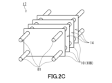
- the structure 17 shown in Fig. 2C includes only the acid gas adsorbent 10B having a flat plate shape as the acid gas adsorbent 10.
- the structure 17 includes a plurality of acid gas adsorbents 10B, which are arranged with gaps between them. The gap between the two acid gas adsorbents 10B functions as the ventilation path 14.
- the structure 17 may further include a fixing member 81 for fixing the plurality of acidic gas adsorbents 10B to ensure the above-mentioned ventilation path 14.
- the fixing member 81 is, for example, a rod.
- a through hole penetrating the acidic gas adsorbent 10B in the thickness direction is formed in each of the plurality of acidic gas adsorbents 10B, and the plurality of acidic gas adsorbents 10B is fixed by inserting a rod as the fixing member 81 into the through hole of each acidic gas adsorbent 10B.
- the rod as the fixing member 81 may be a bolt having a male thread formed on the side.
- the ventilation path 14 can be more reliably ensured by screwing a nut onto the bolt at a position between the two acidic gas adsorbents 10B.
- the nut functions as a spacer.
- each of the multiple acidic gas adsorbents 10B has a rectangular shape in a plan view, and through holes are formed near the four corners. Furthermore, the acidic gas adsorbent 10C has four fixing members 81, which are inserted into the four through holes formed in the four corners of the acidic gas adsorbent 10B.
- the number and positions of the through holes formed in the acidic gas adsorbent 10B, and the number of fixing members 81 are not limited to the example of FIG. 2C.
- the acid gas is efficiently adsorbed by the two acid gas adsorbents 10B while moving through the ventilation path 14 between the two acid gas adsorbents 10B.
- the acidic gas recovery apparatus 100A of the present embodiment includes the above-mentioned acidic gas adsorbent 10 and a medium path 85.
- a heat medium 86 for heating the acidic gas adsorbent 10 passes through the medium path 85 during a desorption operation in which the acidic gas adsorbed by the acidic gas adsorbent 10 is desorbed from the acidic gas adsorbent 10.
- the acid gas adsorbent 10 provided in the acid gas recovery apparatus 100A typically has a sheet shape.
- the acid gas recovery apparatus 100A may include, together with the acid gas adsorbent 10, a support for supporting the acid gas adsorbent 10, or may not include a support.
- the acid gas recovery apparatus 100A preferably includes a plurality of acid gas adsorbents 10.
- the plurality of acid gas adsorbents 10 may be arranged with a gap therebetween, and the gap between two acid gas adsorbents 10 may function as the ventilation path 14.
- the configuration of the acid gas adsorbent 10 and the ventilation path 14 may be the same as the configuration described above for the structures 15 to 17.
- the medium path 85 is preferably composed of a pipe made of a metal such as copper, more specifically, a heat transfer tube.
- the medium path 85 may penetrate the acidic gas adsorbent 10 in the thickness direction of the acidic gas adsorbent 10. More specifically, a through hole is formed in the acidic gas adsorbent 10 that penetrates the acidic gas adsorbent 10 in the thickness direction, and the medium path 85 is inserted into the through hole of the acidic gas adsorbent 10.
- the acidic gas recovery apparatus 100A typically has a structure similar to that of a fin-tube heat exchanger that includes heat transfer fins and heat transfer tubes that penetrate the heat transfer fins.
- the medium path 85 may have a U-shape and may be inserted into two through holes formed in the acidic gas adsorbent 10.
- the number of through holes and the number of medium paths 85 formed in the acidic gas adsorbent 10 are not limited to those shown in FIG. 3A. As an example, four or more through holes may be formed in the acidic gas adsorbent 10, and two or more U-shaped medium paths 85 may be inserted into the through holes of the acidic gas adsorbent 10.
- the medium path 85 functions as a path for the heat medium 86 that heats the acid gas adsorbent 10 during the desorption operation.
- the medium path 85 can also be used as a path for the cooling medium that cools the acid gas adsorbent 10 after the desorption operation.
- the medium path 85 may serve as both a path for the heat medium 86 and a path for the cooling medium.
- the acid gas recovery device 100A further includes a casing (not shown) that houses the acid gas adsorbent 10 and the medium path 85.
- the casing preferably has a mixed gas inlet for sending a mixed gas containing acid gas into the inside of the casing.
- the casing may further have a desorption gas outlet for discharging the desorbed gas desorbed from the acid gas adsorbent 10 to the outside of the casing during desorption operation, and a purge gas inlet for sending a purge gas into the inside of the casing.
- the mixed gas inlet may also serve as the purge gas inlet.
- the casing may have a medium inlet for sending a heat medium 86 or a cooling medium to the medium path 85, and a medium outlet for discharging the heat medium 86 or the cooling medium from the medium path 85.
- the acidic gas recovery apparatus 100A preferably repeatedly performs an adsorption operation in which the acidic gas is adsorbed by the acidic gas adsorbent 10, and a desorption operation in which the acidic gas adsorbed by the acidic gas adsorbent 10 is desorbed from the acidic gas adsorbent 10.
- the acidic gas can be recovered.
- the adsorption operation of the acidic gas recovery apparatus 100A is carried out as follows. First, a mixed gas containing an acidic gas is sent into the inside of the casing through the mixed gas inlet. Examples of the mixed gas include those mentioned above. The mixed gas comes into contact with the acidic gas adsorbent 10 while moving through the ventilation path 14. As a result, the acidic gas adsorbent 10 adsorbs the acidic gas contained in the mixed gas. The adsorption operation is preferably carried out until the adsorption of the acidic gas by the acidic gas adsorbent 10 reaches equilibrium.
- the desorption operation of the acidic gas recovery apparatus 100A is carried out as follows. First, the purge gas is sent into the inside of the casing through the purge gas inlet, and the purge gas is discharged from the desorbed gas outlet to the outside of the casing. This operation allows the mixed gas remaining inside the casing to be discharged to the outside of the casing, and the inside of the casing can be filled with the purge gas. For example, a gas containing a high concentration of acidic gas such as water vapor gas or carbon dioxide can be used as the purge gas. Note that instead of or in addition to the operation of sending the purge gas into the inside of the casing, an operation of depressurizing the inside of the casing may be carried out. This depressurization operation can be carried out by a depressurization device connected to the desorbed gas outlet of the casing.
- the heat medium 86 is sent to the medium path 85.
- the heat medium 86 hot water or high-temperature gas can be used. Specific examples of gases contained in the high-temperature gas include fluorocarbons, carbon dioxide, air, and water vapor.
- the heat medium 86 can be prepared, for example, by using waste heat, a heat pump, or self-heat regeneration.
- the heat medium 86 By sending the heat medium 86 to the medium path 85, heat exchange occurs between the heat medium 86 and the acidic gas adsorbent 10 through the medium path 85, and the acidic gas adsorbent 10 is heated.
- the heating temperature of the acidic gas adsorbent 10 is, for example, 50 to 80°C.
- the acidic gas is desorbed from the acidic gas adsorbent 10.
- the desorbed gas desorbed from the acidic gas adsorbent 10 is discharged from the desorbed gas outlet together with the purge gas. This allows the acidic gas to be recovered. If the purge gas contains water vapor, the water vapor can be removed by cooling the purge gas discharged from the desorbed gas outlet and condensing the water vapor.
- the heat medium 86 it is not necessarily necessary to use the heat medium 86 to heat the acidic gas adsorbent 10. If the support supporting the acidic gas adsorbent 10 functions as a planar heater, the acidic gas adsorbent 10 may be heated by passing electricity through the support.
- the acid gas recovery system 100A is configured so that the heat medium 86 does not come into direct contact with the desorbed gas during desorption operation. This acid gas recovery system 100A can efficiently recover acid gas.
- the recovered acid gas especially carbon dioxide, can be used as a raw material for chemical synthesis or as dry ice.
- the acidic gas recovery apparatus 100A may perform a preparatory operation for performing an adsorption operation after the desorption operation.
- the preparatory operation is performed as follows. First, the supply of purge gas to the inside of the casing is stopped, and the heat medium 86 is discharged from the medium path 85. Next, the cooling medium is sent to the medium path 85. Antifreeze or the like can be used as the cooling medium. Heat exchange between the cooling medium and the acidic gas adsorbent 10 occurs through the medium path 85, and the acidic gas adsorbent 10 is cooled.
- the acidic gas adsorbent 10 is preferably cooled to room temperature (25°C). After the acidic gas adsorbent 10 is cooled, the cooling medium is discharged from the medium path 85, completing preparation for the adsorption operation.
- the acidic gas recovery apparatus is not limited to that shown in FIG. 3A.
- a medium path 85 is formed between two acidic gas adsorbents 10.
- some of the gaps function as the medium path 85, and the remaining gaps function as the ventilation path 14.
- the medium path 85 and the ventilation path 14 are alternately arranged along the arrangement direction of the plurality of acidic gas adsorbents 10.
- the acidic gas recovery apparatus 100B typically has a structure similar to that of a plate-type heat exchanger in which a plurality of heat transfer plates are stacked.
- the acidic gas recovery apparatus 100B preferably includes a support that supports the acidic gas adsorbent 10 together with the acidic gas adsorbent 10.
- the acidic gas adsorbent 10 faces the ventilation path 14, and the support faces the medium path 85.
- a spacer 95 is arranged in the ventilation path 14, and a spacer (not shown) is also arranged in the medium path 85. These spacers are configured to secure the ventilation path 14 and the medium path 85, introduce appropriate fluids into each path, and prevent fluids from leaking into other paths.
- the ventilation path 14 is connected to the external space of the acidic gas recovery apparatus 100B at the back and front of the page, so that the mixed gas may be taken in from the external space into the ventilation path 14. Furthermore, during the desorption operation of the acidic gas recovery apparatus 100B, a member that blocks the connection between the ventilation path 14 and the external space may be arranged between them.
- the acidic gas recovery apparatus 100B further includes a restraining member 90 that restrains the multiple acidic gas adsorbents 10.
- the restraining member 90 preferably includes a pair of plate members 91a, 91b, a rod 92, and a fixing member 93.
- the plate members 91a and 91b are aligned in the arrangement direction of the multiple acidic gas adsorbents 10, and sandwich the multiple acidic gas adsorbents 10.
- the plate members 91a and 91b allow pressure to be applied to the multiple acidic gas adsorbents 10 in the arrangement direction.
- the plate members 91a and 91b may be formed with the desorption gas outlet, purge gas inlet, medium inlet, medium outlet, etc., as described above for the acidic gas recovery apparatus 100A.
- Each of the plate members 91a and 91b has a through hole formed therein, and the rod 92 is inserted into the through hole of the plate members 91a and 91b.
- the rod 92 may be a bolt having a male thread formed on the side.
- the fixing member 93 may fix one of the plate members 91a and 91b and the rod 92 to each other.
- the fixing member 93 is typically a nut having a female thread that can be screwed into the rod 92.
- the restraining member 90 has a fixing member 93a that fixes the plate member 91a and the rod 92 to each other, and a fixing member 93b that fixes the plate member 91b and the rod 92 to each other.
- each of the two rods 92 is fixed by a fixing member 93.
- the number of rods 92, etc. are not limited to the example of FIG. 3B.
- the acidic gas recovery apparatus 100B can implement an operating method similar to that described above for the acidic gas recovery apparatus 100A.
- a medium path 85 is formed between the two acidic gas adsorbents 10. With this configuration, during desorption operation, the entire acidic gas adsorbent 10 can be heated uniformly by passing the heat medium through the medium path 85.
- the acid gas recovery apparatus 100B is configured so that the ventilation path 14 does not interfere with the medium path 85. Therefore, in the acid gas recovery apparatus 100B, the pressure loss caused by the mixed gas passing through the ventilation path 14 during the adsorption operation tends to be small.
- the acid gas recovery apparatus 100B makes it easier to remove components such as the acid gas adsorbent 10. By removing the acid gas adsorbent 10 from the acid gas recovery apparatus 100B, it is easy to replace the acid gas adsorbent 10. Furthermore, by removing each component of the acid gas recovery apparatus 100B, it is easy to perform maintenance such as cleaning operations on each component.
- Example 1 First, 1.06 g of poly(1,2-butanediol)-6 propylene glycol (UNIOL (registered trademark) PB-500, manufactured by NOF Corp.) and 1.06 g of a copolymer of butylene glycol and propylene glycol (UNIOL (registered trademark) PB-700, manufactured by NOF Corp.) were added to a 6 mL screw tube bottle (manufactured by AS ONE Corp.). 0.91 g of ethylene glycol diglycidyl ether (EX-810, manufactured by Nagase ChemteX Corp.) was dissolved in the resulting mixture to prepare a mixture of epoxy monomer and porogen.
- EX-810 ethylene glycol diglycidyl ether
- the mixture was shaken for 2 minutes using a tabletop shaker (Angel Vibrator Digital 60 Hz) set to intensity 5.
- the mixture was then allowed to stand in a thermostatic chamber at 80°C for 2 hours to harden. This resulted in a block-shaped hardened body containing polymer P having amino groups.
- the hardened body was removed from the screw tube bottle and cut into pieces of approximately 3 mm square.
- the hardened body was immersed in ethyl acetate at 60°C for 1 hour, and this operation was repeated twice with liquid exchange. As a result, the porogen was removed from the hardened body, and a porous body containing polymer P was formed.
- the porous body was dried at 60°C for 1 hour and then vacuum dried for another 2 hours to obtain the acidic gas adsorbent of Example 1.
- Examples 2 to 11 The acidic gas adsorbents of Examples 2 to 11 were obtained in the same manner as in Example 1, except that the types and amounts of the raw materials were changed as shown in Table 1.
- the mixture was shaken for 2 minutes using a tabletop shaker (Angel Vibrator Digital 60 Hz) set to intensity 5.
- the mixture was then allowed to stand in a thermostatic chamber at 80°C for 4 hours to harden.
- the hardened body was removed from the screw tube bottle and cut into pieces about 3 mm square.
- the hardened body was immersed in isopropyl alcohol at 60°C for 1 hour, which was repeated twice with liquid replacement.
- the hardened body was immersed in ultrapure water at 60°C for 1 hour, which was repeated twice with liquid replacement.
- the hardened body was immersed in methanol at room temperature for 1 hour.
- the hardened body was air-dried at room temperature for 12 hours and then vacuum-dried at 60°C for 8 hours to obtain an acid gas adsorbent of Comparative Example 1.
- the specific surface area of the prepared acidic gas adsorbent was measured by a method conforming to the provisions of JIS Z8830: 2013. For the measurement, a specific surface area measuring device (manufactured by Microtrack Bell, product name "BERSORP-mini”) was used.
- the glass transition temperature Tg of the polymer contained in the prepared acidic gas adsorbent was measured by the following method. First, about 5 mg of the acidic gas adsorbent was set in a differential scanning calorimeter (manufactured by TA Instruments, DSC2500). Using this device, the temperature was raised from 30 ° C. to 200 ° C. at a heating rate of 10 ° C. / min under a nitrogen atmosphere, and the temperature was held for 1 minute. Next, the temperature was cooled to -50 ° C. at a heating rate of 10 ° C. / min, and the temperature was held for 1 minute, and then the temperature was raised to 200 ° C. at a heating rate of 10 ° C.
- NIR near-infrared spectroscopy
- the peak intensity I A of the absorption peak present near the wave number 4930 cm ⁇ 1 and the peak intensity I B of the absorption peak present near the wave number 6500 cm ⁇ 1 were specified, and the ratio I A /I B was calculated.
- Fig. 4 is a near-infrared absorption spectrum showing the results of NIR for the polymers prepared in Examples 1 and 2. As can be seen from Fig. 4, in the near-infrared absorption spectrum, an absorption peak derived from a primary amino group and a secondary amino group was observed at a wave number of about 6500 cm -1 , and an absorption peak derived from a primary amino group was observed at a wave number of about 4930 cm -1 .
- the adsorption amounts a1 to a3 and the desorption amount b1 were measured by the above-mentioned method. Furthermore, based on these results, the ratio of the desorption amount b1 (mmol/g) to the adsorption amount a1 (mmol/g) (65°C desorption rate) was calculated. For the acidic gas adsorbents prepared in the comparative examples, the adsorption amount a1 was measured by the above-mentioned method.
- EDE Ethylene glycol diglycidyl ether (Nagase Chemtex Corporation, EX-810) JER828: Bisphenol A type epoxy resin (manufactured by Mitsubishi Chemical Corporation, JER828) PETG: Pentaerythritol tetraglycidyl ether (Showa Denko K.K., Showfree (registered trademark) PETG)
- TX N,N,N',N'-tetraglycidyl metaxylenediamine (manufactured by Mitsubishi Gas Chemical Company, Inc., TETRAD-X)
- TC 1,3-bis(N,N-diglycidylaminomethyl)cyclohexane (manufactured by Mitsubishi Gas Chemical Company, Inc., TETRAD-C)
- PEI1200 Polyethyleneimine (manufactured by Nippon Shokubai Co., Ltd., Epomin SP-012, weight average molecular weight approximately 1200) PEI300
- the acid gas adsorbents of the examples had a large nitrogen element density d, and the adsorption amount a1 and desorption amount b1 were also large values.
- the nitrogen element density d was larger and the adsorption amount a1 was also larger than in Examples 7 to 11. It can be said that the acid gas adsorbents of the examples are suitable for adsorbing and desorbing acid gases under relatively mild conditions.
- the acid gas adsorbent of this embodiment can adsorb carbon dioxide in the atmosphere.
Landscapes
- Chemical & Material Sciences (AREA)
- Analytical Chemistry (AREA)
- Chemical Kinetics & Catalysis (AREA)
- Organic Chemistry (AREA)
- Engineering & Computer Science (AREA)
- General Chemical & Material Sciences (AREA)
- Oil, Petroleum & Natural Gas (AREA)
- Solid-Sorbent Or Filter-Aiding Compositions (AREA)
Priority Applications (3)
| Application Number | Priority Date | Filing Date | Title |
|---|---|---|---|
| JP2025513607A JP7749161B2 (ja) | 2023-04-17 | 2024-04-16 | 酸性ガス吸着材、酸性ガス吸着材を備えた構造体、酸性ガス吸着装置、及び酸性ガス吸着材の製造方法 |
| EP24792680.1A EP4699692A1 (en) | 2023-04-17 | 2024-04-16 | Acidic gas adsorbent, structure comprising acidic gas adsorbent, acidic gas adsorption device, and acidic gas adsorbent production method |
| CN202480025570.8A CN121175116A (zh) | 2023-04-17 | 2024-04-16 | 酸性气体吸附材料、具备酸性气体吸附材料的结构体、酸性气体吸附装置及酸性气体吸附材料的制造方法 |
Applications Claiming Priority (2)
| Application Number | Priority Date | Filing Date | Title |
|---|---|---|---|
| JP2023-067196 | 2023-04-17 | ||
| JP2023067196 | 2023-04-17 |
Publications (1)
| Publication Number | Publication Date |
|---|---|
| WO2024219406A1 true WO2024219406A1 (ja) | 2024-10-24 |
Family
ID=93152547
Family Applications (1)
| Application Number | Title | Priority Date | Filing Date |
|---|---|---|---|
| PCT/JP2024/015198 Ceased WO2024219406A1 (ja) | 2023-04-17 | 2024-04-16 | 酸性ガス吸着材、酸性ガス吸着材を備えた構造体、酸性ガス吸着装置、及び酸性ガス吸着材の製造方法 |
Country Status (4)
| Country | Link |
|---|---|
| EP (1) | EP4699692A1 (https=) |
| JP (1) | JP7749161B2 (https=) |
| CN (1) | CN121175116A (https=) |
| WO (1) | WO2024219406A1 (https=) |
Citations (4)
| Publication number | Priority date | Publication date | Assignee | Title |
|---|---|---|---|---|
| US7767004B2 (en) | 2005-03-11 | 2010-08-03 | University Of Ottawa | Functionalized adsorbent for removal of acid gases and use thereof |
| WO2017009241A1 (en) | 2015-07-10 | 2017-01-19 | Climeworks Ag | Amine-functionalized fibrillated cellulose for co2 adsorption and methods for making same |
| WO2021246383A1 (ja) * | 2020-06-02 | 2021-12-09 | 日東電工株式会社 | 酸性ガス吸着・脱離材料 |
| WO2023063051A1 (ja) * | 2021-10-15 | 2023-04-20 | 日東電工株式会社 | 酸性ガス吸着材及び酸性ガス吸着装置 |
Family Cites Families (2)
| Publication number | Priority date | Publication date | Assignee | Title |
|---|---|---|---|---|
| EP4317551A1 (en) * | 2021-03-26 | 2024-02-07 | Nitto Denko Corporation | Fiber, fiber sheet, method for producing fiber, and acidic gas adsorption device |
| US20250018369A1 (en) * | 2021-09-28 | 2025-01-16 | Nitto Denko Corporation | Acidic gas adsorbent and acidic gas adsorption apparatus |
-
2024
- 2024-04-16 CN CN202480025570.8A patent/CN121175116A/zh active Pending
- 2024-04-16 EP EP24792680.1A patent/EP4699692A1/en active Pending
- 2024-04-16 WO PCT/JP2024/015198 patent/WO2024219406A1/ja not_active Ceased
- 2024-04-16 JP JP2025513607A patent/JP7749161B2/ja active Active
Patent Citations (4)
| Publication number | Priority date | Publication date | Assignee | Title |
|---|---|---|---|---|
| US7767004B2 (en) | 2005-03-11 | 2010-08-03 | University Of Ottawa | Functionalized adsorbent for removal of acid gases and use thereof |
| WO2017009241A1 (en) | 2015-07-10 | 2017-01-19 | Climeworks Ag | Amine-functionalized fibrillated cellulose for co2 adsorption and methods for making same |
| WO2021246383A1 (ja) * | 2020-06-02 | 2021-12-09 | 日東電工株式会社 | 酸性ガス吸着・脱離材料 |
| WO2023063051A1 (ja) * | 2021-10-15 | 2023-04-20 | 日東電工株式会社 | 酸性ガス吸着材及び酸性ガス吸着装置 |
Non-Patent Citations (1)
| Title |
|---|
| See also references of EP4699692A1 |
Also Published As
| Publication number | Publication date |
|---|---|
| JP7749161B2 (ja) | 2025-10-03 |
| EP4699692A1 (en) | 2026-02-25 |
| CN121175116A (zh) | 2025-12-19 |
| JPWO2024219406A1 (https=) | 2024-10-24 |
Similar Documents
| Publication | Publication Date | Title |
|---|---|---|
| JP7698728B2 (ja) | 酸性ガス吸着材及び酸性ガス吸着装置 | |
| CN103221127B (zh) | 多孔聚合物材料 | |
| WO2021246383A1 (ja) | 酸性ガス吸着・脱離材料 | |
| JP2017047410A (ja) | 酸性ガス吸着材料、酸性ガス回収ユニット、酸性ガス回収システム、酸性ガスの吸着方法及び回収方法 | |
| EP4316647A1 (en) | Acidic gas adsorbent, method for producing acidic gas adsorbent, and acidic gas adsorption device | |
| JP2025505535A (ja) | 湿度スイング再生工程を使用するガス分離のための高分子アミン収着剤 | |
| WO2022202152A1 (ja) | ファイバー、繊維シート、ファイバーの製造方法及び酸性ガス吸着装置 | |
| JP7698727B2 (ja) | 酸性ガス吸着材、酸性ガス吸着材を備えた構造体、酸性ガス吸着装置、酸性ガス回収装置、酸性ガス吸着材の製造方法、及びシート状構造体 | |
| JP7749161B2 (ja) | 酸性ガス吸着材、酸性ガス吸着材を備えた構造体、酸性ガス吸着装置、及び酸性ガス吸着材の製造方法 | |
| WO2024063153A1 (ja) | ファイバーの製造方法 | |
| US20250214058A1 (en) | Acidic gas adsorbent, structure comprising acidic gas adsorbent, acidic gas adsorption device, and acidic gas adsorbent production method | |
| CA3289316A1 (en) | Acidic gas adsorbent, structure comprising acidic gas adsorbent, acidic gas adsorption device, and acidic gas adsorbent production method | |
| WO2023053803A1 (ja) | 酸性ガス吸着材及び酸性ガス吸着装置 | |
| WO2025197701A1 (ja) | 酸性ガス吸着材、酸性ガス吸着材を備えた構造体、酸性ガス吸着装置、及び、酸性ガス吸着材の製造方法 | |
| WO2025142015A1 (ja) | 酸性ガス吸着材、酸性ガス吸着材を備えた構造体、及び酸性ガス吸着装置 | |
| WO2025204190A1 (ja) | 酸性ガス吸着材、酸性ガス吸着材を備えた構造体、酸性ガス吸着装置、及び、酸性ガス吸着材の製造方法 | |
| WO2025197540A1 (ja) | 酸性ガスの回収方法 | |
| WO2025070430A1 (ja) | 多孔質構造体の製造方法及び多孔質構造体 | |
| CN118176060A (zh) | 酸性气体吸附材料及酸性气体吸附装置 | |
| WO2024071229A1 (ja) | 酸性ガス吸着材シートの製造方法及び酸性ガス吸着材シート | |
| WO2025197539A1 (ja) | 酸性ガスの回収方法 | |
| CN118159358A (zh) | 酸性气体吸附材料、具备酸性气体吸附材料的结构体、酸性气体吸附装置、酸性气体回收装置、酸性气体吸附材料的制造方法及片状结构体 | |
| EP4374950A1 (en) | Sorbent materials for co2 capture, uses thereof and methods for making same | |
| Tan et al. | Effect of Particle Size and Chitosan Loading on Post-Combustion Carbon Dioxide Capture of Chitosan-Coated Natural Zeolite Adsorbent | |
| WO2026055297A1 (en) | Modified weak-base anion exchange resin sorbents for direct air capture of carbon dioxide |
Legal Events
| Date | Code | Title | Description |
|---|---|---|---|
| 121 | Ep: the epo has been informed by wipo that ep was designated in this application |
Ref document number: 24792680 Country of ref document: EP Kind code of ref document: A1 |
|
| WWE | Wipo information: entry into national phase |
Ref document number: 2025513607 Country of ref document: JP |
|
| WWE | Wipo information: entry into national phase |
Ref document number: 2024792680 Country of ref document: EP |
|
| NENP | Non-entry into the national phase |
Ref country code: DE |
|
| ENP | Entry into the national phase |
Ref document number: 2024792680 Country of ref document: EP Effective date: 20251117 |
|
| ENP | Entry into the national phase |
Ref document number: 2024792680 Country of ref document: EP Effective date: 20251117 |
|
| ENP | Entry into the national phase |
Ref document number: 2024792680 Country of ref document: EP Effective date: 20251117 |
|
| ENP | Entry into the national phase |
Ref document number: 2024792680 Country of ref document: EP Effective date: 20251117 |
|
| ENP | Entry into the national phase |
Ref document number: 2024792680 Country of ref document: EP Effective date: 20251117 |
|
| ENP | Entry into the national phase |
Ref document number: 2024792680 Country of ref document: EP Effective date: 20251117 |
|
| ENP | Entry into the national phase |
Ref document number: 2024792680 Country of ref document: EP Effective date: 20251117 |
|
| ENP | Entry into the national phase |
Ref document number: 2024792680 Country of ref document: EP Effective date: 20251117 |
|
| ENP | Entry into the national phase |
Ref document number: 2024792680 Country of ref document: EP Effective date: 20251117 |
|
| WWP | Wipo information: published in national office |
Ref document number: 2024792680 Country of ref document: EP |